JP3959437B2 - Scroll type machine with capacity adjustment mechanism - Google Patents
Scroll type machine with capacity adjustment mechanismDownload PDFInfo
- Publication number
- JP3959437B2 JP3959437B2JP31002995AJP31002995AJP3959437B2JP 3959437 B2JP3959437 B2JP 3959437B2JP 31002995 AJP31002995 AJP 31002995AJP 31002995 AJP31002995 AJP 31002995AJP 3959437 B2JP3959437 B2JP 3959437B2
- Authority
- JP
- Japan
- Prior art keywords
- scroll
- compressor
- chamber
- scroll member
- fluid
- Prior art date
- Legal status (The legal status is an assumption and is not a legal conclusion. Google has not performed a legal analysis and makes no representation as to the accuracy of the status listed.)
- Expired - Fee Related
Links
Images


Classifications
- F—MECHANICAL ENGINEERING; LIGHTING; HEATING; WEAPONS; BLASTING
- F25—REFRIGERATION OR COOLING; COMBINED HEATING AND REFRIGERATION SYSTEMS; HEAT PUMP SYSTEMS; MANUFACTURE OR STORAGE OF ICE; LIQUEFACTION SOLIDIFICATION OF GASES
- F25B—REFRIGERATION MACHINES, PLANTS OR SYSTEMS; COMBINED HEATING AND REFRIGERATION SYSTEMS; HEAT PUMP SYSTEMS
- F25B49/00—Arrangement or mounting of control or safety devices
- F25B49/02—Arrangement or mounting of control or safety devices for compression type machines, plants or systems
- F25B49/022—Compressor control arrangements
- A—HUMAN NECESSITIES
- A47—FURNITURE; DOMESTIC ARTICLES OR APPLIANCES; COFFEE MILLS; SPICE MILLS; SUCTION CLEANERS IN GENERAL
- A47F—SPECIAL FURNITURE, FITTINGS, OR ACCESSORIES FOR SHOPS, STOREHOUSES, BARS, RESTAURANTS OR THE LIKE; PAYING COUNTERS
- A47F3/00—Show cases or show cabinets
- A47F3/04—Show cases or show cabinets air-conditioned, refrigerated
- F—MECHANICAL ENGINEERING; LIGHTING; HEATING; WEAPONS; BLASTING
- F04—POSITIVE - DISPLACEMENT MACHINES FOR LIQUIDS; PUMPS FOR LIQUIDS OR ELASTIC FLUIDS
- F04C—ROTARY-PISTON, OR OSCILLATING-PISTON, POSITIVE-DISPLACEMENT MACHINES FOR LIQUIDS; ROTARY-PISTON, OR OSCILLATING-PISTON, POSITIVE-DISPLACEMENT PUMPS
- F04C18/00—Rotary-piston pumps specially adapted for elastic fluids
- F04C18/02—Rotary-piston pumps specially adapted for elastic fluids of arcuate-engagement type, i.e. with circular translatory movement of co-operating members, each member having the same number of teeth or tooth-equivalents
- F04C18/0207—Rotary-piston pumps specially adapted for elastic fluids of arcuate-engagement type, i.e. with circular translatory movement of co-operating members, each member having the same number of teeth or tooth-equivalents both members having co-operating elements in spiral form
- F04C18/0215—Rotary-piston pumps specially adapted for elastic fluids of arcuate-engagement type, i.e. with circular translatory movement of co-operating members, each member having the same number of teeth or tooth-equivalents both members having co-operating elements in spiral form where only one member is moving
- F—MECHANICAL ENGINEERING; LIGHTING; HEATING; WEAPONS; BLASTING
- F04—POSITIVE - DISPLACEMENT MACHINES FOR LIQUIDS; PUMPS FOR LIQUIDS OR ELASTIC FLUIDS
- F04C—ROTARY-PISTON, OR OSCILLATING-PISTON, POSITIVE-DISPLACEMENT MACHINES FOR LIQUIDS; ROTARY-PISTON, OR OSCILLATING-PISTON, POSITIVE-DISPLACEMENT PUMPS
- F04C27/00—Sealing arrangements in rotary-piston pumps specially adapted for elastic fluids
- F04C27/005—Axial sealings for working fluid
- F—MECHANICAL ENGINEERING; LIGHTING; HEATING; WEAPONS; BLASTING
- F04—POSITIVE - DISPLACEMENT MACHINES FOR LIQUIDS; PUMPS FOR LIQUIDS OR ELASTIC FLUIDS
- F04C—ROTARY-PISTON, OR OSCILLATING-PISTON, POSITIVE-DISPLACEMENT MACHINES FOR LIQUIDS; ROTARY-PISTON, OR OSCILLATING-PISTON, POSITIVE-DISPLACEMENT PUMPS
- F04C28/00—Control of, monitoring of, or safety arrangements for, pumps or pumping installations specially adapted for elastic fluids
- F04C28/02—Control of, monitoring of, or safety arrangements for, pumps or pumping installations specially adapted for elastic fluids specially adapted for several pumps connected in series or in parallel
- F—MECHANICAL ENGINEERING; LIGHTING; HEATING; WEAPONS; BLASTING
- F04—POSITIVE - DISPLACEMENT MACHINES FOR LIQUIDS; PUMPS FOR LIQUIDS OR ELASTIC FLUIDS
- F04C—ROTARY-PISTON, OR OSCILLATING-PISTON, POSITIVE-DISPLACEMENT MACHINES FOR LIQUIDS; ROTARY-PISTON, OR OSCILLATING-PISTON, POSITIVE-DISPLACEMENT PUMPS
- F04C28/00—Control of, monitoring of, or safety arrangements for, pumps or pumping installations specially adapted for elastic fluids
- F04C28/06—Control of, monitoring of, or safety arrangements for, pumps or pumping installations specially adapted for elastic fluids specially adapted for stopping, starting, idling or no-load operation
- F—MECHANICAL ENGINEERING; LIGHTING; HEATING; WEAPONS; BLASTING
- F04—POSITIVE - DISPLACEMENT MACHINES FOR LIQUIDS; PUMPS FOR LIQUIDS OR ELASTIC FLUIDS
- F04C—ROTARY-PISTON, OR OSCILLATING-PISTON, POSITIVE-DISPLACEMENT MACHINES FOR LIQUIDS; ROTARY-PISTON, OR OSCILLATING-PISTON, POSITIVE-DISPLACEMENT PUMPS
- F04C28/00—Control of, monitoring of, or safety arrangements for, pumps or pumping installations specially adapted for elastic fluids
- F04C28/08—Control of, monitoring of, or safety arrangements for, pumps or pumping installations specially adapted for elastic fluids characterised by varying the rotational speed
- F—MECHANICAL ENGINEERING; LIGHTING; HEATING; WEAPONS; BLASTING
- F04—POSITIVE - DISPLACEMENT MACHINES FOR LIQUIDS; PUMPS FOR LIQUIDS OR ELASTIC FLUIDS
- F04C—ROTARY-PISTON, OR OSCILLATING-PISTON, POSITIVE-DISPLACEMENT MACHINES FOR LIQUIDS; ROTARY-PISTON, OR OSCILLATING-PISTON, POSITIVE-DISPLACEMENT PUMPS
- F04C28/00—Control of, monitoring of, or safety arrangements for, pumps or pumping installations specially adapted for elastic fluids
- F04C28/18—Control of, monitoring of, or safety arrangements for, pumps or pumping installations specially adapted for elastic fluids characterised by varying the volume of the working chamber
- F04C28/22—Control of, monitoring of, or safety arrangements for, pumps or pumping installations specially adapted for elastic fluids characterised by varying the volume of the working chamber by changing the eccentricity between cooperating members
- F—MECHANICAL ENGINEERING; LIGHTING; HEATING; WEAPONS; BLASTING
- F04—POSITIVE - DISPLACEMENT MACHINES FOR LIQUIDS; PUMPS FOR LIQUIDS OR ELASTIC FLUIDS
- F04C—ROTARY-PISTON, OR OSCILLATING-PISTON, POSITIVE-DISPLACEMENT MACHINES FOR LIQUIDS; ROTARY-PISTON, OR OSCILLATING-PISTON, POSITIVE-DISPLACEMENT PUMPS
- F04C28/00—Control of, monitoring of, or safety arrangements for, pumps or pumping installations specially adapted for elastic fluids
- F04C28/24—Control of, monitoring of, or safety arrangements for, pumps or pumping installations specially adapted for elastic fluids characterised by using valves controlling pressure or flow rate, e.g. discharge valves or unloading valves
- F04C28/26—Control of, monitoring of, or safety arrangements for, pumps or pumping installations specially adapted for elastic fluids characterised by using valves controlling pressure or flow rate, e.g. discharge valves or unloading valves using bypass channels
- F04C28/265—Control of, monitoring of, or safety arrangements for, pumps or pumping installations specially adapted for elastic fluids characterised by using valves controlling pressure or flow rate, e.g. discharge valves or unloading valves using bypass channels being obtained by displacing a lateral sealing face
- F—MECHANICAL ENGINEERING; LIGHTING; HEATING; WEAPONS; BLASTING
- F04—POSITIVE - DISPLACEMENT MACHINES FOR LIQUIDS; PUMPS FOR LIQUIDS OR ELASTIC FLUIDS
- F04C—ROTARY-PISTON, OR OSCILLATING-PISTON, POSITIVE-DISPLACEMENT MACHINES FOR LIQUIDS; ROTARY-PISTON, OR OSCILLATING-PISTON, POSITIVE-DISPLACEMENT PUMPS
- F04C28/00—Control of, monitoring of, or safety arrangements for, pumps or pumping installations specially adapted for elastic fluids
- F04C28/28—Safety arrangements; Monitoring
- F—MECHANICAL ENGINEERING; LIGHTING; HEATING; WEAPONS; BLASTING
- F25—REFRIGERATION OR COOLING; COMBINED HEATING AND REFRIGERATION SYSTEMS; HEAT PUMP SYSTEMS; MANUFACTURE OR STORAGE OF ICE; LIQUEFACTION SOLIDIFICATION OF GASES
- F25B—REFRIGERATION MACHINES, PLANTS OR SYSTEMS; COMBINED HEATING AND REFRIGERATION SYSTEMS; HEAT PUMP SYSTEMS
- F25B1/00—Compression machines, plants or systems with non-reversible cycle
- F25B1/04—Compression machines, plants or systems with non-reversible cycle with compressor of rotary type
- F—MECHANICAL ENGINEERING; LIGHTING; HEATING; WEAPONS; BLASTING
- F25—REFRIGERATION OR COOLING; COMBINED HEATING AND REFRIGERATION SYSTEMS; HEAT PUMP SYSTEMS; MANUFACTURE OR STORAGE OF ICE; LIQUEFACTION SOLIDIFICATION OF GASES
- F25B—REFRIGERATION MACHINES, PLANTS OR SYSTEMS; COMBINED HEATING AND REFRIGERATION SYSTEMS; HEAT PUMP SYSTEMS
- F25B41/00—Fluid-circulation arrangements
- F25B41/30—Expansion means; Dispositions thereof
- F25B41/31—Expansion valves
- F25B41/34—Expansion valves with the valve member being actuated by electric means, e.g. by piezoelectric actuators
- F25B41/35—Expansion valves with the valve member being actuated by electric means, e.g. by piezoelectric actuators by rotary motors, e.g. by stepping motors
- G—PHYSICS
- G05—CONTROLLING; REGULATING
- G05D—SYSTEMS FOR CONTROLLING OR REGULATING NON-ELECTRIC VARIABLES
- G05D23/00—Control of temperature
- G05D23/19—Control of temperature characterised by the use of electric means
- G05D23/1906—Control of temperature characterised by the use of electric means using an analogue comparing device
- G05D23/1909—Control of temperature characterised by the use of electric means using an analogue comparing device whose output amplitude can only take two discrete values
- F—MECHANICAL ENGINEERING; LIGHTING; HEATING; WEAPONS; BLASTING
- F04—POSITIVE - DISPLACEMENT MACHINES FOR LIQUIDS; PUMPS FOR LIQUIDS OR ELASTIC FLUIDS
- F04C—ROTARY-PISTON, OR OSCILLATING-PISTON, POSITIVE-DISPLACEMENT MACHINES FOR LIQUIDS; ROTARY-PISTON, OR OSCILLATING-PISTON, POSITIVE-DISPLACEMENT PUMPS
- F04C2270/00—Control; Monitoring or safety arrangements
- F04C2270/01—Load
- F04C2270/015—Controlled or regulated
- F—MECHANICAL ENGINEERING; LIGHTING; HEATING; WEAPONS; BLASTING
- F04—POSITIVE - DISPLACEMENT MACHINES FOR LIQUIDS; PUMPS FOR LIQUIDS OR ELASTIC FLUIDS
- F04C—ROTARY-PISTON, OR OSCILLATING-PISTON, POSITIVE-DISPLACEMENT MACHINES FOR LIQUIDS; ROTARY-PISTON, OR OSCILLATING-PISTON, POSITIVE-DISPLACEMENT PUMPS
- F04C2270/00—Control; Monitoring or safety arrangements
- F04C2270/86—Detection
- F—MECHANICAL ENGINEERING; LIGHTING; HEATING; WEAPONS; BLASTING
- F04—POSITIVE - DISPLACEMENT MACHINES FOR LIQUIDS; PUMPS FOR LIQUIDS OR ELASTIC FLUIDS
- F04C—ROTARY-PISTON, OR OSCILLATING-PISTON, POSITIVE-DISPLACEMENT MACHINES FOR LIQUIDS; ROTARY-PISTON, OR OSCILLATING-PISTON, POSITIVE-DISPLACEMENT PUMPS
- F04C23/00—Combinations of two or more pumps, each being of rotary-piston or oscillating-piston type, specially adapted for elastic fluids; Pumping installations specially adapted for elastic fluids; Multi-stage pumps specially adapted for elastic fluids
- F04C23/008—Hermetic pumps
- F—MECHANICAL ENGINEERING; LIGHTING; HEATING; WEAPONS; BLASTING
- F25—REFRIGERATION OR COOLING; COMBINED HEATING AND REFRIGERATION SYSTEMS; HEAT PUMP SYSTEMS; MANUFACTURE OR STORAGE OF ICE; LIQUEFACTION SOLIDIFICATION OF GASES
- F25B—REFRIGERATION MACHINES, PLANTS OR SYSTEMS; COMBINED HEATING AND REFRIGERATION SYSTEMS; HEAT PUMP SYSTEMS
- F25B2600/00—Control issues
- F25B2600/02—Compressor control
- F25B2600/026—Compressor control by controlling unloaders
- F25B2600/0261—Compressor control by controlling unloaders external to the compressor
- F—MECHANICAL ENGINEERING; LIGHTING; HEATING; WEAPONS; BLASTING
- F25—REFRIGERATION OR COOLING; COMBINED HEATING AND REFRIGERATION SYSTEMS; HEAT PUMP SYSTEMS; MANUFACTURE OR STORAGE OF ICE; LIQUEFACTION SOLIDIFICATION OF GASES
- F25B—REFRIGERATION MACHINES, PLANTS OR SYSTEMS; COMBINED HEATING AND REFRIGERATION SYSTEMS; HEAT PUMP SYSTEMS
- F25B2700/00—Sensing or detecting of parameters; Sensors therefor
- F25B2700/19—Pressures
- F25B2700/193—Pressures of the compressor
- F25B2700/1933—Suction pressures
- F—MECHANICAL ENGINEERING; LIGHTING; HEATING; WEAPONS; BLASTING
- F25—REFRIGERATION OR COOLING; COMBINED HEATING AND REFRIGERATION SYSTEMS; HEAT PUMP SYSTEMS; MANUFACTURE OR STORAGE OF ICE; LIQUEFACTION SOLIDIFICATION OF GASES
- F25B—REFRIGERATION MACHINES, PLANTS OR SYSTEMS; COMBINED HEATING AND REFRIGERATION SYSTEMS; HEAT PUMP SYSTEMS
- F25B2700/00—Sensing or detecting of parameters; Sensors therefor
- F25B2700/21—Temperatures
- F25B2700/2117—Temperatures of an evaporator
- F—MECHANICAL ENGINEERING; LIGHTING; HEATING; WEAPONS; BLASTING
- F25—REFRIGERATION OR COOLING; COMBINED HEATING AND REFRIGERATION SYSTEMS; HEAT PUMP SYSTEMS; MANUFACTURE OR STORAGE OF ICE; LIQUEFACTION SOLIDIFICATION OF GASES
- F25B—REFRIGERATION MACHINES, PLANTS OR SYSTEMS; COMBINED HEATING AND REFRIGERATION SYSTEMS; HEAT PUMP SYSTEMS
- F25B49/00—Arrangement or mounting of control or safety devices
- F25B49/005—Arrangement or mounting of control or safety devices of safety devices
- Y—GENERAL TAGGING OF NEW TECHNOLOGICAL DEVELOPMENTS; GENERAL TAGGING OF CROSS-SECTIONAL TECHNOLOGIES SPANNING OVER SEVERAL SECTIONS OF THE IPC; TECHNICAL SUBJECTS COVERED BY FORMER USPC CROSS-REFERENCE ART COLLECTIONS [XRACs] AND DIGESTS
- Y02—TECHNOLOGIES OR APPLICATIONS FOR MITIGATION OR ADAPTATION AGAINST CLIMATE CHANGE
- Y02B—CLIMATE CHANGE MITIGATION TECHNOLOGIES RELATED TO BUILDINGS, e.g. HOUSING, HOUSE APPLIANCES OR RELATED END-USER APPLICATIONS
- Y02B30/00—Energy efficient heating, ventilation or air conditioning [HVAC]
- Y02B30/70—Efficient control or regulation technologies, e.g. for control of refrigerant flow, motor or heating
Landscapes
- Engineering & Computer Science (AREA)
- Mechanical Engineering (AREA)
- General Engineering & Computer Science (AREA)
- Physics & Mathematics (AREA)
- Thermal Sciences (AREA)
- Fluid Mechanics (AREA)
- General Physics & Mathematics (AREA)
- Automation & Control Theory (AREA)
- Rotary Pumps (AREA)
- Applications Or Details Of Rotary Compressors (AREA)
- Structures Of Non-Positive Displacement Pumps (AREA)
Description
Translated fromJapanese【0001】
【産業上の利用分野】
この発明は容量調整機構を備えたスクロール式機械、特にスクロール式圧縮機に、関するものである。
【0002】
【発明の背景】
空気調和用及び冷凍用の圧縮機中に容量調整機構を採り入れることはしばしば、系がおかれ得る広範囲の負荷条件によりよく適応するために望まれる事柄である。容量調整を得るための、吸入口の制御から吐出ガスの吸入口へのバイパスによる戻しに至るまでの数多くの方法が、利用されて来ている。スクロール式圧縮機の容量調整はよく、吸入遅延法によって行われている。この方法では開放されると、噛合ったスクロール翼間に形成された流体圧縮ポケットを吸入ガス供給側に対し連通させるポートを、種々の位置に配して設け、これにより吸入ガスの圧縮開始点を遅らせる。この容量調整法は、実際には圧縮機の圧縮比を減少させることとする。かかる系は圧縮機の容量を減少するのに有効ではあるが、圧縮機の予定した量のみの負荷解除を行い得るだけで、負荷解除量はスクロール螺旋翼に沿った負荷解除ポートの配置に依存する。多数のポートを様々な位置に設けて多段階の負荷解除を得ることも可能であるが、その方法によると高価につき、またそれぞれの組のポートの開閉を制御する別々の複数制御機構を設けるための追加のスペースが必要となる。
【0003】
この発明はかかる不具合を解消し、単一の制御機構のみを利用して100パーセントないし全容量から実質的に零の容量までの連続した範囲の負荷解除を、可能としようとするものである。またこの発明は、所望されるどのような程度の圧縮機負荷解除状態に対しても圧縮機及び/又は冷却系の運転効率を最大限のものとすることも、狙いとする。
【0004】
【発明の要約】
この発明は圧縮機の負荷解除を、圧縮機の運転サイクル中に予定した時間だけ両スクロール部材を軸線方向又は放射方向において周期的に分離させることによって、達成する。特にこの発明は一方のスクロール部材を軸線方向又は放射方向に沿って他方のスクロール部材に対し時刻パルス的に遠近移動させ、これにより両スクロール螺旋翼の翼先又は翼側面を横切る向きの、両螺旋翼間の高圧側流体圧縮ポケットから低圧側流体圧縮ポケットへの、そして最終的には吸入側への漏れ径路を、周期的に生じさせる。スクロール螺旋翼の翼先又は翼側面の密封状態と密封解除状態との間の相対的な時間を制御することによって、実質的に任意の度合いの負荷解除を、単一の制御系を用いて達成できる。また冷却系中の種々の条件を感知することにより各サイクルの圧縮機負荷時間と負荷解除時間を、所与の容量の圧縮機について全体としてみた系の効率が最大となるように選択することができる。例えば圧縮機を50パーセントの容量で稼働させるのが望ましい場合には圧縮機を交互に、5秒間だけ負荷状態とし5秒間だけ負荷解除(無負荷)状態とするか7秒間だけ負荷状態とし7秒間だけ負荷解除状態とする。これによってその都度の特定の運転条件に対してより高い効率を得ることができる。
【0005】
この発明は後述する実施例に示すように極めて広範囲の様々な態様で実施できるが、この発明に係るスクロール式圧縮機では一方のスクロール部材が軸線方向又は放射方向に沿い他方のスクロール部材に対し相対的に、全範囲での圧縮機の負荷解除ないし容量調整を得るように往復動される。単一の制御系を用いて全範囲での容量調整を可能としたこと、及び負荷及び負荷解除運転の時間の選択を可能としたことにより、極めて効率的な系を、比較的低いコストで提供できる。
【0006】
特定の用途において系効率をさらに改善するために、上述した時刻パルス的な負荷解除法を、従来技術として前述した吸入遅延法と組合せるのが望ましい場合もある。例えば吐出弁のすぐ下流側での系圧力が設計全負荷時レベルよりも低いレベルにある場合、圧縮機の圧縮比により流体圧縮ポケットから放出される時の圧縮流体の圧力が高過ぎることとなる、過大圧縮と呼ばれている状態が生じる。この状態で容量を減少させる最も有効な方法は圧縮機の圧縮比を、したがって流体圧縮ポケットを出る圧縮流体の圧力を、同圧力が吐出弁のすぐ下流側での系圧力と等しいか僅かにのみ高い値となるように減らして、過大圧縮による仕事損失を無くすことである。しかし過大圧縮状態が一旦無くされてから系の条件によってさらに容量を減らすことが指示されると、時刻パルス的な容量調整法を利用するのが、同法が過小圧縮と呼ばれている状態、つまり流体圧縮ポケットから放出される時の圧縮流体の圧力が吐出弁のすぐ下流側の圧力よりも低くなる事態、が生じるのを回避させることからして、より有効である。したがってこの発明は時刻パルス的な容量調整機構と吸入遅延による容量調整機構とを組合せてある機械も含むものであって、そのような組合せにより上述した状態が起きる可能性が高い系の効率を、何れか一方の容量調整機構のみにより達成されよりも高めることができる。
【0007】
またこの発明は圧縮機の負荷解除によりモータ負荷が減少されている期間中にモータの運転効率を向上させるよう、モータの各種運転パラメータを制御するモータ用のコントローラを組込んである機械も、提供するものである。
【0008】
この発明の他の特徴と長所は、添付図面を参照して行う以下の説明から明瞭に理解できる。
【0009】
【実施例】
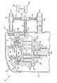
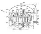
図1にはこの発明に従った密閉型スクロール式圧縮機を、符号10で全体を指して示してある。スクロール式圧縮機10は本願出願人の所有に係る米国特許No.5,102,316に記載されたタイプのものであり、外殻12を備えている。この外殻12の内部には固定子14と回転子16を有する駆動モータ、回転子16を取付けてあるクランク軸18、このクランク軸18を回転可能に支持する上下の軸受箱20,22、及び圧縮装置24を配設してある。
【0010】
圧縮装置24は上部軸受箱20上で支持されている旋回スクロール部材26を含み、この旋回スクロール部材26はクランクピン28及び駆動ブッシュ30を介して、クランク軸18に対し駆動を受けるように接続されている。旋回スクロール部材26に対し噛合せた非旋回スクロール部材32を設けてあり、この非旋回スクロール部材32は上部軸受箱20に対し複数本のボルト34及びそれと組合せたスリーブ部材36を用いて、軸線方向に沿い動き得るように取付けてある。両スクロール部材26,32間でこれらのスクロール部材間の相対回転を阻止するように働くオルダム接手38を、設けてある。
【0011】
外殻12内の上端近くには仕切り板40を配置してあり、この仕切り板40によって外殻12内の上端部に吐出チャンバ42が区画形成されている。
【0012】
運転時に非旋回スクロール部材32に対し相対的に旋回スクロール部材26が旋回動するにつれ吸入ガスが、吸入口44を通して外殻12内に引込まれ、外殻12内から非旋回スクロール部材32中に設けてある入口46を通して圧縮装置24中へと引込まれる。両スクロール部材26,32上に設けられ互いに噛合されている螺旋翼は可動の流体ポケットを区画形成し、これらの流体ポケットはスクロール部材26の旋回動の結果として、次第に容積を減少しつつ放射方向の内側に移動して入口46から入った吸入ガスを圧縮する。圧縮ガスは非旋回スクロール部材32中に設けられた吐出ポート48、及び通路50を介して吐出チャンバ42中に放出される。適当な圧力応動吐出弁51を、吐出ポート48内に設けるのが好ましい。
【0013】
非旋回スクロール部材32にはまたその上面に、環状の凹溝52を形成してある。上記した通路50を形成してある、概して不規則な形状のシリンダ状部材54をその一端部で凹溝52内に突入させて、該凹溝52内を上下のチャンバ56,58に分割してある。シリンダ状部材54の他端部は仕切り板40に対し、密封的に固定してある。非旋回スクロール部材32の上端には環状リング60を取付けてあり、このリング60は軸線方向に沿うフランジ62を含み、該フランジ62でシリンダ状部材54に対し摺接して上方側チャンバ56の上端開口を密封する。
【0014】
上方側チャンバ56は後述するように非旋回スクロール部材32を旋回スクロール部材26から分離させるための分離チャンバとして用いられ、シリンダ状部材は、一端で該チャンバ56に開口する通路64を有する。この通路64の他端には流体ライン66が接続され、流体ライン66は外殻12を通して外部へ延び、電磁弁68に接続されている。電磁弁68から第2の流体ライン70を、吸入口44へと接続された吸入ライン72へと導いてあり、また電磁弁68から第3の流体ライン74を、吐出チャンバ42から外部に延びる吐出ライン76へと導いてある。
【0015】
通常の完全負荷状態での作動を得るよう、非旋回スクロール部材32を付勢して旋回スクロール部材26に対し密封係合させるため、非旋回スクロール部材32には、付勢チャンバとして機能する下方側チャンバ58と吸入圧力と吐出圧力間の中間圧力にある流体ポケットとを連通させるブリード孔78を、設けてある。したがって下方側チャンバ58は中間圧力をとり、該中間圧力と吐出ポート48の領域で非旋回スクロール部材32の上面に作用する吐出圧力とによって該スクロール部材32に対し軸線方向下方向きの付勢力が及ぼされ、同スクロール部材32が旋回スクロール部材26に対し密封的に係合する。同時に電磁弁68は、上方側チャンバ56を吸入ライン72に対し流体ライン66,70を介して連通させる位置をとる。
【0016】
圧縮装置24の負荷解除を行うために電磁弁68は制御モジュール80からの信号に応動して、流体ライン66,70間の連通を断ち流体ライン66を吐出ライン76へと連通させて上方側チャンバ56の圧力を吐出ガスの圧力にまで高めるように、作動せしめられる。この吐出圧力からする付勢力は密封用の付勢力に打克って非旋回スクロール部材32を、旋回スクロール部材26から引離して上方向きに移動させる。この上方向き移動によってスクロール部材26,32の翼先と端板間に漏れ径路が形成され、吸入ガスの引続いた圧縮を実質的に消失させる。負荷解除が生じるとき吐出弁51は閉鎖位置へと動き、吐出チャンバ42或いは下流の系から高圧流体が逆流するのを阻止する。吸入ガスの圧縮を再開すべきときは電磁弁68が、流体ライン66,74を介しての上方側チャンバ56と吐出ライン76間の連通が断たれ上方側チャンバ56が流体ライン66,70を介し吸入ライン72と連通して軸線方向の分離力が無くされることとなる位置へと、作動せしめられる。これによって下方側チャンバ58内の中間圧力と通路50内で作用する吐出圧力との協働作用により、非旋回スクロール部材32が旋回スクロール部材26に対し密封的に係合することになる。
【0017】
制御モジュール80はそれに接続された1個又は複数個のセンサー82であって、その時点で存在する特定の条件が要求する負荷解除の度合いを決定するための情報を制御モジュール80に対し与えるセンサー82を、有するのが好ましい。この情報に基づいて制御モジュール80は適切に時限を設定された逐次信号を電磁弁68へ送って、流体ライン66が交互に吐出ライン76と吸入ライン72とに連通されることとなるように、電磁弁68の位置を切替え制御する。例えばその時点での条件が圧縮装置24を全容量の50%で稼働させることが望ましいと指示しているとすると制御モジュール80は電磁弁68を、流体ライン66を吸入ライン72と連通させる位置に10秒間だけおき、次に流体ライン66を吐出ライン76と連通させる位置に同様に10秒間だけ切替えるように、作動させ得る。この方法での電磁弁68の連続した切替えにより運転時間の50%の時間だけ圧縮が行われ、圧縮装置24の出力が全負荷容量の50%に減少する。感知される条件が変動するにつれて制御モジュール80は圧縮装置24の負荷状態と負荷解除状態とでの相対的な運転時間を、系の変更する要求に応じて圧縮装置24の容量が完全負荷容量ないし100%容量と完全無負荷容量ないし0%容量との間で変更されることとなるように、変更制御する。
【0018】
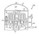
図2,3は、図1のものに類似して軸線方向で負荷解除を得るスクロール式圧縮機84を示している。この圧縮機84が図1のものと相違する点は上方側チャンバ56を吸入ライン及び吐出ラインと連通させるための構造にあり、類似の部分は図1で用いたのと同じ符号で指して示してある。図1に示した通路64は環状リング60に設けた通路86に置換えられており、この通路86は一端で上方側チャンバ56に開口し他端で放射方向外向きのリング側壁面に開口している。屈曲性の流体ライン88を、通路86の外端から外殻12を貫通する管接手90へと導いてあり、管接手90は第2のライン92により電磁弁68に接続してある。図1の場合と同様に電磁弁68は、吸入ライン72及び吐出ライン76に対しそれぞれ接続されている流体ライン70及び74を有し、センサー82により感知される条件に応じ制御モジュール80によって制御され、図1の実施例について述べたと同様の態様で非旋回スクロール部材32を図2に示す位置と図3に示す位置間で移動させる。本実施例は高圧吐出チャンバ42から外部へ延びる余分の管接手を設ける必要を無くすが、非旋回スクロール部材32と環状リング60との軸線方向の動きを可能とするために屈曲性の流体導管88を用いる必要がある。本実施例ではシリンダ状部材54が仕切り板40に対し、部材54の上端部にねじ嵌めされたナット55によって密封的に固定されている。また本実施例では図1に示した吐出弁51が、外殻12に取付けられた吐出逆止弁93に置換えられている。吐出流路の或る部分に逆止弁を設けることは、圧縮機が負荷解除状態にあるときに系からの圧縮ガスの逆流を阻止するため極く望ましい点に、留意されるべきである。
【0019】
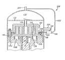
図4,5は軸線方向での負荷解除分離を得るための圧力流体を、圧縮装置を出る吐出ガスから直接に取出すこととしてある、別の実施例に係るスクロール式圧縮機94を示している。本実施例では筒状部材96を適宜の方法で仕切り板40に取付けてあり、この筒状部材96は放射方向外向きのフランジ98を有し、該フランジ98を非旋回スクロール部材32上面の環状凹溝内に臨ませて該凹溝内を上方側チャンバ(分離チャンバ)56と下方側チャンバ(付勢チャンバ)58とに区画している。筒状部材96には、圧縮吐出ガスを吐出ポート48から吐出チャンバ42へと導く通路50も形成してある。軸線方向に沿う穴100を筒状部材96内に設けてあり、この穴100は筒状部材96の上端に開口し流体導管102を支承するものとされている。流体導管102は外殻12の頂壁を貫通して外部に延出され、電磁弁68に接続されている。本実施例の電磁弁68も、吸入ライン72及び吐出ライン76に対しそれぞれ接続されている流体ライン70及び74を有し、前述したのと同様に適当なセンサー82からの信号に応じて制御モジュール80により制御される。
【0020】
穴100内にはバルブ部材104を、軸線方向に沿い移動可能に配置してある。このバルブ部材104は径縮小部106を有し、第1の位置では筒状部材96中に設けられた放射方向の通路108と110とを連通させて上方側チャンバ56内を吸入側へ接続して減圧し、第2の位置では放射方向の通路110を、同様に筒状部材96中に設けられている放射方向の通路112と連通させて吐出通路50から上方側チャンバ56内に吐出ガスを導くものに、構成されている。穴100の底と通路50間を連通させてバルブ部材104の作動中に該部材104下方の領域からガスを抜くベント通路113も、設けてある。バルブ部材104を上記した第2の位置に移動付勢するスプリング114も設けてあり、バルブ部材104は上記した第1の位置に対しては通路112,113を介して穴100に入る加圧吐出流体によって移動付勢される。
【0021】
図4,5に示す状態ではバルブ部材104と電磁弁68の両者が完全負荷運転位置にあり、電磁弁68は流体導管102を吸入ライン72と連通させる位置をとり、バルブ部材104は上方側チャンバ56を吸入圧力の外殻12内部に連通させて該チャンバ56内を減圧する位置をとっている。圧縮機の負荷解除が望まれるときには、電磁弁68が流体導管102を流体ライン74へと連通させる位置へと作動せしめられ、これによって加圧吐出流体がバルブ部材104の上端面に作用することになる。この加圧流体とスプリング114によりバルブ部材104は下方向きに動かされ、放射方向の通路110と108間の連通を断ち放射方向の通路110と112間を連通させる。したがって吐出圧力の流体が上方側チャンバ56中に流入し、通路78により中間圧力の流体ポケットと連通させてある下方側チャンバ58内の中間圧力からする付勢力に打克って非旋回スクロール部材32を、旋回スクロール部材26から引き離して上方向きに移動させる。本実施例では吐出圧力の流体を上方側チャンバ56に供給するための流路が比較的短くされていることから、圧縮機の迅速な負荷解除が達成される。
【0022】
図6は図4,5の実施例に類似した変形実施例を示し、本実施例では電磁弁68が外殻12内に配置されている。本実施例によれば外殻12の高圧部分を貫通する追加の流体導管を設ける必要が無くされ、電磁弁68を作動させるための電気配線のみしか必要でない。他の点で図6の実施例の構造と作用は図4,5の実施例について説明したのと実質的に等しく、対応する部分は同一の符号で指してある。
【0023】
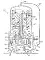
以上に説明した実施例は非旋回スクロール部材を軸線方向で旋回スクロール部材から引離すように移動させる負荷解除構造に係るが、同様の原理を旋回スクロール部材に対し適用することも可能である。図7−15はそれぞれ、そのような実施例に係る。
【0024】
図7に示すスクロール式圧縮機140はこれ迄述べて来たスクロール式圧縮機と、非旋回スクロール部材142が軸受箱144に対し移動不能に取付けられ、旋回スクロール部材146が軸線方向で可動である点で相違している。また圧縮機140は側部高圧型機械(high side machine)、つまり吸入ラインないし吸入管149が非旋回スクロール部材142に対し直接に接続され、外殻12の内部が吐出圧力にある機械である。本実施例では旋回スクロール部材146が軸線方向に移動可能であり、旋回スクロール部材146と主軸受箱144間に区画形成された圧力チャンバ148により非旋回スクロール部材142と係合するように移動付勢されている。主軸受箱144中には環状凹溝150を設けてあり、この環状凹溝150内に適当な環状の弾性シール部材152を配設して旋回スクロール部材146の下面に対し密封的に係合させ、もって圧力チャンバ148と吐出圧力にある外殻12の内部との間の流体連通を阻止してある。第2の環状シール154を主軸受箱144中に、クランク軸18を取り囲ませて設けて、該クランク軸18に沿う流体漏れを防止してある。小寸法の通路156を、旋回スクロール部材146の端板を貫通させて設けてチャンバ148を、吸入圧力と吐出圧力間の中間圧力にある流体ポケットと連通させてある。またチャンバ148から外向きに延びる通路158を主軸受箱144中に設けて、該通路158に流体ライン160の一端を接続してある。流体ライン160の他端は外殻12を通して外方へ延び、電磁弁162に接続されている。第2の流体ライン164を、電磁弁162と吸入ライン149間に設けてある。
【0025】
圧縮機の稼働時にチャンバ148は中間圧力の流体を供給されて旋回スクロール部材146を、非旋回スクロール部材142と密封的に係合するように移動付勢する。このとき電磁弁162は、ライン160,164間の連通を断つ位置をとっている。圧縮機140の負荷を解除するためには電磁弁162が、流体ライン160を流体ライン164へと連通させてチャンバ148内の中間圧力を吸入側へと抜く位置へと、作動せしめられる。これにより旋回スクロール部材146が両スクロール部材の螺旋翼間の流体ポケット内の圧力により、弾性シール部材152を圧縮しつつ軸線方向下向きに動かされ、両スクロール部材142,146の翼先と端板間に流体漏れ径路が形成される。通路156を介してチャンバ148に吸入圧力よりも若干高い圧力の流体が供給され続けるが、通路158及び流体ライン160,164の通路156に対する相対的な流路断面積は、電磁弁162が吸入ライン149とチャンバ148間の連通を維持する位置にある限りチャンバ148内の圧力が、旋回スクロール部材146を非旋回スクロール部材142に対し密封係合するように移動付勢するには不十分である圧力に留められるように、設定されている。電磁弁162は、前述したのと実質的に同一の態様で圧縮機140を周期的に負荷及び負荷解除するように、周期的に開閉される。
【0026】
図8は図7のものの変形に係る圧縮機140aを示しており、本変形例では複数個のスプリング166を設けている。スプリング166は軸受箱144a中に設けた複数個の凹溝168に支承され旋回スクロール部材146の端板に対し、該スクロール部材146の非旋回スクロール部材142に対する密封係合を援けるように、作用させてある。スプリング166は主として、圧縮機140aの起動時に旋回スクロール部材146に対し初期付勢力を与えるように機能するが、運転中に電磁弁162が閉鎖されたとき圧縮機140aをより迅速に負荷するのにも役立つ。
【0027】
図9は、図7の実施例の別の変形例に係る圧縮機140bを示している。本変形例では外殻12に仕切り部材170を設けて該外殻12内を、導管176を介して吐出ポート174が接続される高圧吐出チャンバ172と圧縮装置が配置される低圧力の吸入圧力領域とに区画している。また本実施例では図7に示した軸シール154を、環状の弾性シール部材150bの放射方向内側に同心配置して設けた第2の環状シール178に置換えている。したがってクランクピン28及び駆動ブッシュ30を配置してある領域は吸入圧力にあり、このため同領域に対し同様に吸入圧力にある外殻内低部の油溜まりから潤滑油を供給することに関連する問題が避けられる。図7及び図8の各実施例では油溜まりが吐出圧力にあり、このため駆動要素28,30に対し潤滑油を供給することについての問題は存在しない。図7に示した圧力チャンバ148に対応する圧力チャンバ148bは、両環状シール150b,178間に区画形成されている。
【0028】
図10に示す圧縮機140cは図9の圧縮機140bと、チャンバ148b内の中間圧力流体よりする付勢力に加えて複数個のスプリング180によっても旋回スクロール部材156を付勢することとしている点を除いては、実質的に等しい。スプリング180は旋回スクロール部材156と主軸受箱144間に配置され、図8の実施例について説明したのに類似して、主に起動時の初期付勢力を与えるように機能するが圧縮機140cを再負荷するときにも役立つ。
【0029】
図11に示す実施例では非旋回スクロール部材182に環状凹溝184を設けて、該凹溝184内に環状のピストン部材186を移動可能に配置している。ピストン部材186の下面は旋回スクロール部材146の端板189における放射方向外向きの張出し部187に接当させてあり、またピストン部材186の内周面及び外周面上には放射方向内側の環状シール188及び放射方向外側の環状シール190を設けて、環状凹溝184の内周壁面及び外周壁面に密封的に係合させてある。非旋回スクロール部材182中に放射方向の通路192を設けて、内端で環状凹溝184の上部に連通させると共に外端に流体導管194を接続してある。流体導管194は外殻12を貫通して外部に延出させ、電磁弁196に接続してある。第2の流体導管198により電磁弁196を吸入ライン200に対し接続し、また第3の流体導管202により電磁弁196を吐出ライン204へと接続している。
【0030】
通常の完全負荷運転条件の下で旋回スクロール部材146は、ブリード通路208を介して付勢チャンバ206に供給される中間流体圧力により軸線方向に沿い移動付勢されて、非旋回スクロール部材182に対し密封的に係合する。このとき環状ピストン部材186上方の環状凹溝184領域は、電磁弁196及び流体導管194,198を介して吸入ライン200に連通し、減圧された状態にある。条件により圧縮機の部分的な負荷解除が望ましいことが指示されると、電磁弁196が作動せしめられて流体導管194を、流体導管202を介して吐出ライン204へと連通させる。そのときは環状ピストン部材186上方側の領域が吐出圧力の流体によって加圧され、これによって旋回スクロール部材146がピストン部材186を介し軸線方向下方向きに移動付勢される。前述したのと同様に電磁弁196の周期的な切替えにより圧縮機の反復した負荷及び負荷解除が、電磁弁196に関連させて設けてあるセンサー及び制御モジュール(図示せず)により決定される負荷解除割合で行われる。本実施例の圧縮機は側部高圧型機械に構成され、したがって吸入ラインないし吸入管200は非旋回スクロール部材182の吸入口に直接に接続されている。
【0031】
図12に図示の圧縮機208は、図11に図示の軸線方向での負荷解除構造と図9に図示の旋回スクロール部材付勢構造とを組合せてなる。したがって図9,11について用いたのと同じ符号で各部分を指し、繰返えしの説明は省略する。本実施例では旋回スクロール部材付勢用の圧力チャンバ148bを、環状凹溝184及び環状ピストン部材186によって区画形成された負荷解除用の、ピストン部材186上方のチャンバから完全に分離させている。
【0032】
図13に図示の圧縮機210は類似して、図8に図示の中間圧力付勢構造と図11に図示の軸線方向での負荷解除用圧力付勢構造とを組合せてなる。したがって図8,11で用いたのと同じ符号で各部分を指し、繰返えしの説明は省略する。
【0033】
図14はさらに別の実施例に係る圧縮機212を示し、本実施例では外殻12が吐出圧力の上部チャンバ214と、吸入圧力と吐出圧力間の中間圧力の下部チャンバ216とを含む。したがって吸入ライン234は非旋回スクロール部材224に対し直接、接続されている。適当な環状シール225を旋回スクロール部材222と非旋回スクロール部材224間に、これらのスクロール部材の外周端付近で設けてある。旋回スクロール部材222は、通路226を介し下部チャンバ216内に供給される中間圧力によって非旋回スクロール部材224に対し密封的に係合するよう、移動付勢されている。圧縮機212の負荷解除を行うために電磁弁228を設けてあり、この電磁弁228は、外殻12内へ延びて主軸受箱233中に設けられている通路231に接続されている第1の流体ライン230を有する。吸入ライン234と電磁弁228間を接続する第2の流体ライン232を、設けてある。電磁弁228が開放されると、旋回スクロール部材222の下面に作用していた中間圧力が通路231、流体ライン230、電磁弁228及び流体ライン232により吸入側に抜かれる。通路231、流体ライン230,232及び電磁弁228の寸法ないし流路断面積を、通路226を通して流れる流量と軸受箱233と旋回スクロール部材222の端板間の領域中への流体漏れ量との合計量よりも多い流量が与えられるように設定してあるので、旋回スクロール部材222に作用する付勢力が軽減され、これにより両スクロール部材螺旋翼間の流体ポケット内の流体力により旋回スクロール部材222が、非旋回スクロール部材224を離れて移動する。電磁弁228が閉鎖されると直ちに、外殻12内の下部チャンバ216内の中間圧力流体の漏れ流れと通路226からの流れとの組合せにより旋回スクロール部材222に対する付勢力が迅速に回復し、それにより完全な圧縮が再開される。本実施例でも前述の各実施例におけるのと同様に、適切に感知された系の条件に対応した制御モジュール(図示せず)からの信号に応動した電磁弁228の周期的な作動によって圧縮機の周期的な負荷及び負荷解除が行われて、容量を100%から0%の範囲で調整できる。
【0034】
図15に示す圧縮機236は、図14に示したような旋回スクロール部材付勢用の外殻内の中間圧力下部チャンバと図11に示した吐出圧力による負荷解除構造との各特徴を組合せた実施例に係る。したがって対応する部分は図11,14で用いたのと同じ符号で指し、繰返えしの説明は行わない。また図8,10及び13について述べたのと同様に複数個のスプリング238を、主軸受箱242中に設けた凹溝240内に配置して設けて旋回スクロール部材222の端板の下面に作用させてある。前述したのと同様にスプリング238は主として、初期起動中に旋回スクロール部材222を、非旋回スクロール部材182に対し密封的に係合するように移動付勢するように働き、また圧縮機236の再負荷を促進するようにも働く。
【0035】
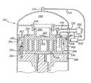
図16はこの発明のさらに他の実施例に係る圧縮機244を示し、この圧縮機244は図1に図示のものに類似していて外殻12が、その内部を吐出チャンバ248と吸入圧力の下部チャンバ250とに区画する分割板246を有する。分割板246には、軸線方向に可動の非旋回スクロール部材258の吐出ポート256から圧縮流体を導くための流路254を形成するシリンダ状部材252を、取付けてある。非旋回スクロール部材258の上面には環状凹溝を設けてあり、この環状凹溝内を、シリンダ状部材252に設けた放射方向外向きの環状フランジ264によって上方側チャンバ(分離チャンバ)260と下方側チャンバ(付勢チャンバ)262とに区画してある。下方側チャンバ262は通路266によって中間圧力の流体ポケットに連通させてあり、これにより非旋回スクロール部材258を旋回スクロール部材268に対し密封的に係合するように移動付勢する付勢力が、与えられることとされている。シリンダ状部材252に対し密封係合状態で摺接する環状プレート部材269を非旋回スクロール部材258に取付けて、上方側チャンバ260の上端開口を封鎖してある。非旋回スクロール部材258上には、圧力応動吐出逆止弁270も設けてある。
【0036】
二方電磁弁271を、吐出管272に対し流体ライン274を介し接続すると共に上方側チャンバ260に対し流体ライン276とシリンダ状部材252中の通路278とを介し接続して、設けてある。非旋回スクロール部材258とプレート部材269間にベント通路280を設けて、上方側チャンバ260と外殻12内の吸入圧力の下部チャンバ250とに開口させてある。このベント通路280は上方側チャンバ260内を連続して、吸入圧力へと減圧するように働く。電磁弁271が閉鎖位置にあるときは、圧縮機244は完全に負荷されている。しかし感知された条件に応じて制御モジュール(図示せず)により電磁弁271が開放位置へと作動せしめられると、上方側チャンバ260内が実質的に吐出圧力にまで加圧され、これに基づく力が、非旋回スクロール部材258に対し旋回スクロール部材268向きに作用している吐出圧力及び中間圧力による付勢力に打克つ。したがって非旋回スクロール部材258が軸線方向上方向きに移動して、圧縮機244が負荷解除される。本実施例では流体ライン274,276及び通路278の寸法ないし流路断面積をベント通路280の寸法ないし流路断面積に対し相対的に、負荷解除を得るのに十分な圧力が上方側チャンバ260内に成立するような値のものに、選択しなければならない。またこれらの流路の相対的な寸法関係は、負荷解除を達成し無負荷状態を維持するのに必要な吐出ガスの量に対してだけではなく、圧縮機244を負荷状態と無負荷状態との間で切替える速度に対しても、影響する。
【0037】
図17は、図16に図示の圧縮機244の変形に係る圧縮機244aを示している。本実施例は、中間圧力チャンバ(付勢チャンバ)262中に付勢部材としての複数個のスプリング282を設けている点でのみ図16の実施例と相違しており、対応する部分は図16で用いたのと同じ符号で指してある。前述の場合同様にスプリング282は主として起動中に非旋回スクロール部材258を、旋回スクロール部材268に対し密封的に係合するように付勢するが、圧縮機244aの再負荷を促進するようにも働く。他の点で圧縮機244aの作用は、図1−16について述べて来たのと実質的に等しい。
【0038】
図18には、この発明の別の実施例に係る圧縮機284を示してある。この圧縮機284の外殻12は、その内部を吐出チャンバ290と吸入圧力の下部チャンバ292とに区画する分割板286を有する。分割板286には、軸線方向に可動の非旋回スクロール部材296の円筒状部分に対し密封係合状態で摺接するシリンダ状部材294を取付けてあり、これによって吐出ポート300からの吐出流体流路298が形成されている。非旋回スクロール部材296には圧力応動吐出逆止弁302も設けられていて、この逆止弁302は吐出チャンバ290からの流体ポケット中への吐出流体の逆流を阻止する。非旋回スクロール部材296はその外周縁上に1対の環状段部304,306を有し、これらの環状段部304,306は主軸受箱312上の相補的な部分308,310と協力して、ほぼ環状の分離チャンバ314を区画形成している。非旋回スクロール部材296はまた、放射方向外向きに突出する下端のフランジ部316を含み、このフランジ部316は主軸受箱312上の放射方向内向きのフランジ部318と協力して、非旋回スクロール部材296の軸線方向に沿う分離運動を制限するように働く。
【0039】
電磁弁320を、分離チャンバ314に対し主軸受箱312中の通路322と流体ライン324とを介し接続して、設けてある。電磁弁320はまた、流体ライン326により吐出ライン330に対し接続されていると共に流体ライン328により吸入ライン332に対し接続されている。
【0040】
圧縮機284が通常の完全負荷状態で運転されているときは前述の場合同様に電磁弁320は開放位置にあって、分離チャンバ314を吸入ライン332に対し、通路322と流体ライン324,328を介し連通させる。この条件の下では流路298内で非旋回スクロール部材296の上面に作用するところの、吐出チャンバ290中の吐出流体圧力に基づいて生じる付勢力が、非旋回スクロール部材296を移動付勢して旋回スクロール部材334に対し密封的に係合させる。圧縮機284の負荷を解除するのが望ましい場合には電磁弁320が作動せしめられて、分離チャンバ314を吐出ライン330に対し、流体ライン326,324と通路322とを介し連通させる。その結果、分離チャンバ314内に生成する圧力が非旋回スクロール部材296に対し作用している下方向き付勢力に打克って、非旋回スクロール部材296を軸線方向上方向きに移動させ旋回スクロール部材334から引離すことにより、圧縮機284の負荷解除が得られる。圧縮機284を再負荷するためには電磁弁320が、分離チャンバ314を吸入ライン332に対し通路332と流体ライン324,328を介し連通させて、分離チャンバ314内の吐出圧力の流体を吸入側に抜くように作動せしめられ、これにより非旋回スクロール部材296に作用している付勢力が該スクロール部材296を軸線方向下方向きに移動させて、旋回スクロール部材334との密封的な係合状態へと戻す。前述したのと同様の態様で電磁弁320の作動は、1個又は複数個のセンサーによって感知される系の条件に応じ適当な制御モジュール(図示せず)により、圧縮機284が所要のように周期的に負荷及び負荷解除されるよう、制御される。
【0041】
図18の実施例に類似した別の実施例に係る圧縮機336を、図19に示してある。図19において、図18で用いたのと同じ符号は同様の部分を指す。図19の実施例では外殻12内の下部チャンバ292が、旋回スクロール部材334中の通路338を介して供給される中間圧力にある。この中間圧力は旋回スクロール部材334に対し上方向きの付勢力を加えるようにも作用する。環状段部308,310を有するリング部材340を別形成して、主軸受箱342に固定してある。リング部材340は旋回スクロール部材334の端板に対し重なり合うように延出させてある部分344も有し、この部分344は圧縮機336が負荷解除状態にあるときに旋回スクロール部材334の上方向き移動を制限するように働く。内部の屈曲性の吸入管346を設けて、吸入ライン332と非旋回スクロール部材296とに接続してある。吸入管346の非旋回スクロール部材296に対する接続部には逆止弁348を設けてあって、この逆止弁348は、圧縮機336の負荷が解除されたとき圧縮流体の逆流を阻止する。任意に設けてよい吸入制御装置350も吸入ライン332中に、流体ライン328の接続点よりも上流側で設けられている。この吸入制御装置350は制御モジュール(図示せず)により制御されて吸入ライン332中の吸入ガス流れを制限し、もって圧縮機336の無負荷運転から負荷運転への移行中と初期起動時に分離チャンバ314内の減圧を促進する。圧縮機336の周期的な負荷及び負荷解除を含めての他の作用は、これ迄述べて来たのと実質的に等しい。
【0042】
さらに他の実施例に係る圧縮機352を、図20に示してある。この圧縮機352は、締結具360により位置決めしてある複数個のブッシング358を用いて主軸受箱356に支持させてある、軸線方向に可動の非旋回スクロール部材354を有する。ブッシング358と締結具360は互いに協力して非旋回スクロール部材354を、その制限された軸線方向移動を可能としつつ精密且つ回転不能に位置付ける。別体の環状フランジ付きリング362を非旋回スクロール部材354に取付けてあり、このリング362は放射方向の外側に配置されているフランジ付き固定リング部材364と協力して、密閉された環状の分離チャンバ366を区画形成している。リング部材364は分離チャンバ366に開口する通路368を含み、この通路368に一端を接続してある流体ライン370の他端に接続して、電磁弁372を設けてある。電磁弁372は流体ライン374によって吐出ライン378に接続され、流体ライン376によって吸入ライン380に接続されている。圧縮機352の作用はこれ迄に述べて来たものと実質的に等しく、電磁弁372は分離チャンバ366が周期的に吐出圧力流体及び吸入圧力流体に接続されることとして、圧縮機352を周期的に負荷及び負荷解除する。
【0043】
図21に図示の圧縮機382は、図20の圧縮機352における分離チャンバ形成構造と図19の圧縮機336における吸入ガス供給構造及び外殻内下部中間圧力構造とを組合せた構造のものである。したがって図19,20で用いたのと同じ符号で対応部分を指し、本実施例について繰返しの説明をすることは省く。
【0044】
図22は、さらに他の実施例に係る圧縮機384を示している。この圧縮機384は図16に図示の圧縮機244と、流体導管390を介し吸入ライン386に対し接続してある二方電磁弁386を含む点、及び以下に述べる変形された通路構造を採用し図16に示した上方側チャンバ260形成用のカバー部材ないしプレート部材269を省略した点を除いて、実質的に等しい。したがって図16の圧縮機244の各部分に対応する部分は同一の符号で指して、繰返しの説明は行わない。また軸線方向に沿い可動の非旋回スクロール部材258の支持構造は図20の実施例について説明したのと実質的に等しく、したがって図20で用いたのと同じ符号で対応する部分を指して繰返しの説明を行わないこととする。本実施例でも電磁弁386を第1の流体ライン392、第2の内部の屈曲性流体ライン394、及び非旋回スクロール部材258中に設けた放射方向の通路396によって、チャンバ262に対し接続している。また複数個の分離用スプリング398を、ブッシング358と同心配置して主軸受箱400と非旋回スクロール部材258の下面との間に設けている。
【0045】
通常の完全負荷状態の運転下で非旋回スクロール部材258は、通路254内で該スクロール部材258の上面に作用する吐出圧力と通路266を介してチャンバ262内に導かれる中間流体圧力とに基づく力によって、旋回スクロール部材268に対し密封的に係合するように移動付勢されている。本条件下で電磁弁386は閉鎖位置にあり、チャンバ262と吸入ライン388間の流体連通を阻止する。感知された系条件によって圧縮機384の負荷解除を行うのが望ましいと指示されると、電磁弁386が開放してチャンバ262を、通路396及び流体ライン394,392,390を介し吸入ライン388へと接続し、非旋回スクロール部材258に加わる中間圧力による付勢力を解除する。この付勢力解除により両スクロール部材間の圧縮下にある流体に基づく力及びスプリング398によって加えられる力により非旋回スクロール部材258が、軸線方向で動かされて旋回スクロール部材268との密封係合を解除され、これによって圧縮機384の負荷解除が得られる。通路396、流体ライン394,392,390及び電磁弁386の寸法ないし流路断面積は勿論、通路266の寸法ないし流路断面積に対し相対的に、チャンバ262の適切な減圧が達成されるように設定されなければならない。圧縮機384の周期的な負荷解除及び再負荷によって、前述したのと実質的に同一の態様で系条件に対応した容量調整が達成される。
【0046】
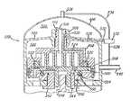
この発明は双回転型(両スクロール旋回型)のスクロール式圧縮機に適用するのにも、好適している。双回転型スクロール式圧縮機に係る数実施例を、図23−28に示してある。
【0047】
図23には、双回転型のスクロール式圧縮機402を示してある。圧縮機402は第1及び第2のスクロール部材404,406を備え、これらのスクロール部材404,406は外殻408内で上下の軸受部材410,412により回転可能に、且つ、軸線方向で互いから離間可能に支持されている。軸受部材410はプレート部材415中に形成してあり、プレート部材415はまた、上部スクロール部材404中の吐出ポート416を出る圧縮流体が通路418を介して内部に導かれる吐出チャンバ414を、区画形成している。吐出逆止弁420を、吐出ポート416に対し重ね合せ関係として設けてある。下部スクロール部材406は下部ハウジング422内で、該ハウジング422と共に回転できるように支持されている。上部スクロール部材404を取囲む上部ハウジング424を設けて下部ハウジング422に取付け、これらのハウジング422,424と上部スクロール部材404とによって中間圧力付勢チャンバ426と分離チャンバ428とを区画形成してある。上部スクロール部材404中に流体通路430を設けて、この通路430により中間圧力の流体ポケットを付勢チャンバ426に対し接続してある。付勢チャンバ426に供給される中間圧力は通路418内で上部スクロール部材404に作用する吐出流体圧力と共に、上部スクロール部材404を移動付勢して圧縮機の完全負荷運転中に該スクロール部材404を下部スクロール部材406に対し密封的に係合させることとする。
【0048】
上部スクロール部材404中には第2の通路432も設けられていて、この通路432は分離チャンバ428から、上部スクロール部材404の上端の円筒状ハブ部分の外周面に形成してある環状凹溝434にまで延びるものとされている。環状凹溝434は軸受410中に設けた通路438と連通させてあり、通路438はプレート部材415内を通して放射方向の外向きに延びている。
【0049】
電磁弁440を設けてあり、この電磁弁440は適当なセンサー(図示せず)によって感知される系の条件に応じ、制御モジュール(図示せず)によって制御されるものに設計されている。電磁弁440は通路438に対し接続された第1の流体ライン442、吐出ライン448に対し接続された第2の流体ライン444、及び吸入ライン452に対し接続された第3の流体ライン450を有する。
【0050】
圧縮機402が完全負荷条件下で運転されているとき電磁弁440は、分離チャンバ428を吸入ライン452に対し通路432、凹溝434、通路438及び流体ライン442,450を介して連通させる位置にある。圧縮機402の負荷解除を得るためには電磁弁440が、分離チャンバ428を吐出ライン448に対し接続して分離チャンバ428内を吐出圧力へと加圧するように、作動する。分離チャンバ428内の吐出圧力流体に基づく力によって上部スクロール部材404は軸線方向で、下部スクロール部材406から分離し該スクロール部材406との密封係合を解除するように移動せしめられ、これによって圧縮機402の負荷解除が得られる。電磁弁440の周期的な作動により圧縮機402の周期的な負荷解除が、前述したのと実質的に同一の態様で達成される。
【0051】
図24は、他の実施例に係る双回転型スクロール式圧縮機454を示している。本実施例の圧縮機454は図23に示した圧縮機402と、中間圧力付勢チャンバを設けずして、軸線方向で可動の上部スクロール部材404を下部スクロール部材406との密封係合を得るように付勢することを、上部スクロール部材404の上面に作用する吐出圧力にのみ得ることとした点でのみ、相違しており、他の構造と作用は実質的に同一である。したがって対応する部分を同一の符号で指して、繰返しの説明を避ける。
【0052】
別の実施例の双回転型スクロール式圧縮機456を、図25に示してある。この圧縮機456は図23に示した圧縮機402と、圧縮機402で設けた中間圧力付勢チャンバ426に代えて複数個のスプリング458を、ハウジング424の放射方向内向きの部分460と上部スクロール部材404の上面間に配置して設けている点でのみ、実質的に相違している。したがって対応する部分を同一の符号で指して、繰返しの説明を省略する。スプリング458は通路418内の吐出圧力と協力して、上部スクロール部材404を軸線方向で移動付勢して下部スクロール部材406に対し密封的に係合させる。圧縮機456の他の作用は全て、圧縮機402について前述したのと実質的に等しい。
【0053】
さらに他の実施例に係る双回転型スクロール式圧縮機462を、図26に示してある。この圧縮機462は以下に述べる点を除いて前述の圧縮機402,454及び456に類似のものであるので、対応する部分は同一の符号で指示する。
【0054】
図26に示す圧縮機462の圧縮装置は密閉外殻464内の底部に配置され、圧縮機402,454及び456と対比して倒立させた構造のものである。スクロール部材406に吐出ポート466が設けられ、この吐出ポート466は圧縮流体を、逆止弁470を介してチャンバ468内へと導く。圧縮流体はチャンバ468から外殻464内の上方側に配置のモータ室472へ、クランク軸476中の通路474を通して導かれる。モータ室472内には、固定子478とクランク軸476に固定してある回転子480とを備える駆動モータを設置してある。軸線方向で可動のスクロール部材404を、外殻464の下部ハウジング部分483中に形成した円筒状軸受箱482中で回転可能に支持してあり、該スクロール部材404と軸受箱482とによって吐出圧力付勢チャンバ484を区画形成してある。チャンバ484に対し吐出圧力の流体を供給するために主軸受箱488中に通路486を設けてあり、この通路486は、下部ハウジング部分483中の第2の通路490に接続してある。通路490はチャンバ484に開口させてあり、したがってモータ室472からチャンバ484内へ高圧の吐出流体を導いて、完全負荷状態での圧縮機運転中にスクロール部材404を付勢してスクロール部材406に対し密封的に係合させることとする。下部ハウジング部分483中には、環状凹溝434を流体ライン442へと連らねる第3の通路492も設けてある。チャンバ484は図例とは異なり、中間圧力の流体ポケットをチャンバ484に対し接続する通路をスクロール部材404の端板に形成することによって中間圧力の流体により加圧することもでき、その場合には通路486,490を設ける必要が無くされる。また図例とは異なり吐出圧力の流体をチャンバ484に、吐出ポート466が開口する流体ポケットからチャンバ484に流体を導く通路をスクロール部材404の端板に形成することによっても、供給可能である。
【0055】
図26に図示の圧縮機462の作用は、制御モジュールとセンサー(図示せず)によって制御される電磁弁440の作動に対応した周期的な負荷及び負荷解除を含めて、前記圧縮機454の作用と実質的に等しい。
【0056】
図27は他の実施例に係る双回転型スクロール式圧縮機494を示し、本実施例では下方側の駆動スクロール部材が軸線方向で移動可能とされている。圧縮機494は外殻496を備え、この外殻496内で上部及び下部スクロール部材498,500が回転可能に支持されている。吐出チャンバ504を下方の吸入圧力チャンバ506から隔離する仕切り板502を設けてあり、この仕切り板502は円筒状軸受部508を有し、該軸受部508により上部スクロール部材498を、該スクロール部材498の筒状部分510で回転可能に支持している。筒状部分510の内部は、吐出ポート514から吐出逆止弁516を経て吐出チャンバ504に至る吐出流体流路512に、形成されている。上部スクロール部材498は、下部スクロール部材500に向けて開口する環状凹溝518を有する。この凹溝518内には環状のピストン部材520を上下動可能に配置してあり、このピストン部材520はその上方の分離チャンバ522内が加圧されると下部スクロール部材500に対し分離力を加えるものとされている。分離チャンバ522に対し吐出圧力の流体を供給するために上部スクロール部材498中に通路524を設けてあり、この通路524はチャンバ522から上方へ延びて筒状部分510中を通過し、さらに放射方向の外向きに延びて環状凹溝526へと開口している。第2の通路528を、ほぼ放射方向の外向きに沿わせて仕切り板502中に形成してあり、この通路528は流体ライン530によって電磁弁532に接続されている。電磁弁532は吐出管536へ導かれた流体ライン534、及び吸入ライン540へ導かれた他の流体ライン538を有する。
【0057】
下部スクロール部材500は下部軸受542を介して回転可能に支持されており、内面にスプラインを形成してある中心ハブ部分544を有していて、外面にスプラインを形成してある駆動軸546に、軸線方向に沿い移動可能にスプライン嵌めされている。下部スクロール部材500の端板には中間圧力ブリード通路548を形成してあり、この通路548は両スクロール部材498,500の螺旋翼間の中間圧力流体ポケットから付勢用の圧力流体を、下方の付勢チャンバ550へと導くように働く。プレート部材552を上部スクロール部材498の下面に取付けてあり、このプレート部材552は環状凹溝554を有し、該凹溝554内には環状シール556を配置してある。このシール556は下部スクロール部材500の下面に係合して、チャンバ550を吸入圧力チャンバ506から密閉する。
【0058】
完全に負荷された運転中に下部スクロール部材500は、チャンバ550中の中間圧力流体により生ぜしめられる付勢力によって軸線方向上方向きに移動付勢され、上部スクロール部材498に対し密封的に係合している。この条件下で電磁弁532は、分離チャンバ522を吸入ライン540に対し連通させる位置をとっている。系の条件によって低容量出力が望ましいことが指示されると電磁弁532が、分離チャンバ522を吐出ライン536に対し連通させる位置へと作動せしめられ、これにより該チャンバ522内が加圧されてピストン部材520が下降する。ピストン部材520の下降動によって下部スクロール部材500が下方向きに動かされ、上部スクロール部材498との密封係合を解除する。電磁弁532が分離チャンバ522内の圧力を吸入ライン540へと抜く位置に戻されると、付勢チャンバ550内の中間圧力に基づく付勢力によって下部スクロール部材500が、上部スクロール部材498に対し密封的に係合する位置へと戻される。負荷状態と無負荷状態での運転切替えは、前述した場合同様に制御モジュールとセンサーによって制御される。
【0059】
図28は、下記の点を除いて図27の圧縮機494と実質的に同一の双回転型スクロール式圧縮機558を、示している。したがって対応する部分を同一の符号で指し、それについての再度の説明は行わない。圧縮機558は下部スクロール部材500を移動付勢して上部スクロール部材498に対し密封的に係合させるのに、通路560を介して付勢チャンバ550に供給される吐出圧力の流体を利用している。他の点で圧縮機558の作用は、図27の圧縮機494について述べたのと実質的に等しい。
【0060】
この発明の他の実施例に係る圧縮機562を、図29に示してある。圧縮機562は以下に述べる点を除いては図20に示した圧縮機352と等しく構成されているので、対応する部分については同一の符号を用いて指し反復した説明は省略する。図29の圧縮機562は外殻566の一部を形成する仕切り板564を有し、この仕切り板564は外殻566の内部を、高圧吐出チャンバ568と低圧吸入部分570とに仕切っている。仕切り板564は中心の円筒状部分572を有し、この円筒状部分572によって軸線方向に可動の非旋回スクロール部材354を、該スクロール部材354の円筒状部分574で密封的に支承している。スクロール部材円筒状部分574は放射方向に沿う複数個の穴576を有し、これらの穴576は仕切り板円筒状部分572中の穴578と整列配置され、吐出ポート580から吐出逆止弁582を経て吐出チャンバ568に至る吐出ガス流路579の一部を形成している。スクロール部材円筒状部分574には流路579の上端を閉鎖するカバー板584を取付けてあり、このカバー板584は仕切り板円筒状部分572と協力して中間圧力付勢チャンバ586を区画形成している。非旋回スクロール部材354中には中間圧力の流体ポケットから上方へ延びて付勢チャンバ586に開口する流体通路588を設けてあり、この流体通路588によって、非旋回スクロール部材354を軸線方向で移動付勢し旋回スクロール部材590に対し密封的に係合させるための流体圧力を、チャンバ586に供給することとされている。圧縮機562の周期的な負荷及び負荷解除を含めての作用は、圧縮機352及びその他の実施例について前述したのと実質的に等しい。
【0061】
図29の圧縮機562の一部について変形を施した圧縮機592を図30に示してあり、対応する部分は同一の符号で指してある。図30の圧縮機592は付勢チャンバ586に接続された流体ライン596を有する二方電磁弁594を備え、この電磁弁594は第2の流体ライン598によって吸入ライン380に対し接続されている。また図20,29に示した分離チャンバ366を形成するためのリング部材362,366を無くし、その代わりに複数個の付勢用スプリング600を、ブッシング358と同心配置して設けている。
【0062】
図30の実施例において完全負荷状態での運転中は、付勢チャンバ586内の中間流体圧力に基づく付勢力により非旋回スクロール部材354が下方向きに移動付勢され、前述したのと同様にスプリング600による付勢力に打克って旋回スクロール部材590に対し密封的に係合する。条件により負荷解除が望ましいと指示されると電磁弁594が、負荷運転中にチャンバ586から吸入ライン380への圧力排除を阻止していた閉鎖位置から開放位置へと切替えられ、これによりチャンバ586から吸入ライン380へと圧力が抜かれて非旋回スクロール部材354に作用していた付勢力が消失される。この付勢力の消失によりスプリング600の力と圧縮中の流体の圧力に基づく力とによって、非旋回スクロール部材354が軸線方向上方向きに動かされ旋回スクロール部材590との係合を解除する。電磁弁594は前述の場合同様に、センサーに呼応した制御手段により周期的に作動せしめられ、圧縮機592の周期的な負荷及び負荷解除を行って所望される度合いの容量調整を達成する。
【0063】
これ迄述べて来た実施例は密閉型電動圧縮機に関するものであるが、この発明は、例えば自動車の空気調和系用の圧縮機のように外部駆動を採用する圧縮機にも適用できる。そのような環境で本発明を利用すると、今日の空気調和系で普通に利用されている高価なクラッチ系統を無くすことができる。
【0064】
図31は、外部駆動源によるものとされたスクロール式圧縮機602を示している。圧縮機602の構造は以下に述べる点を除いて図16の圧縮機244に類似しているので、対応する部分を同一の符号で指し反復した説明を省略する。
【0065】
図31に示す圧縮機602は、図16の圧縮機244におけるのとは異なり三方電磁弁604を備えており、このため電磁弁604を吐出ライン272に対し接続する流体ライン606と吸入ライン610に対し接続する流体ライン608とを、含んでいる。所望の場合には勿論、二方電磁弁を利用することも可能である。電磁弁604が圧縮機の完全負荷状態での運転時にチャンバ260から吸入ライン610へと直接に圧力を排出するものに設計されているので、図16の圧縮機244で設けていた連続排出用の通路280は省いてある。圧縮機602の駆動軸612は、適宜の軸受手段616及びシール手段618を通してハウジング614の外部に突出させてあり、自動車のエンジン等の適宜の外部動力源に対し通例のプーリー及びVベルト等によって接続することとされている。
【0066】
運転中に外部動力源は駆動軸612を連続駆動し、旋回スクロール部材268を連続して旋回動させる。空気調和系の条件により冷却が要求されると、適当な制御手段により電磁弁604がチャンバ260を吸入ライン610に対し連通させる位置に置かれ、これによりチャンバ260内の圧力に基づく分離力が無くされ、通路266を介して中間圧力の流体を供給されるチャンバ262が、通路254内で非旋回スクロール部材258の面に作用する吐出圧力に基づく付勢力に加えての付勢力を生じさせて、非旋回スクロール部材258を旋回スクロール部材268向きに移動付勢して該スクロール部材268に対し密封的に係合させる。空気調和系の要求が満たされると電磁弁604が、チャンバ260を吐出ライン272に対し連通させる位置へと移され、これによって生ぜしめられる分離力により非旋回スクロール部材258が軸線方向で、旋回スクロール部材268との密封係合を解除するように移動せしめられて、圧縮機602の負荷解除が得られる。圧縮機602の周期的な制御は前述したのと同様の態様で行い得、自動車における用途ではクラッチの必要性が無くされる。
【0067】
以上に説明して来た実施例では圧縮機の負荷解除を得るために圧縮された流体を利用して来たが、この発明はまた、2つのスクロール部材のうちの一者又は両者の軸線方向移動を生じさせる他のタイプの力発生手段を用いて圧縮機の負荷解除を達成する構成のものともできる。図32−34はそれぞれ、そのような実施例を示している。
【0068】
図32に示す密閉型圧縮機620はプレート624を有する外殻622を備え、プレート624は外殻622の内部を、吐出チャンバ626と吸入圧力の下方部分628とに区画している。外殻622内に固定配置した軸受箱630にクランク軸632を回転可能に支持させてあり、クランク軸632は旋回スクロール部材634に対し、該スクロール部材634を旋回駆動するように接続されている。非旋回スクロール部材636を軸受箱630上でブッシング638及び締結具640により、該スクロール部材636がブッシング638に沿って移動可能であるが周方向及び放射方向には動き得ないように、支持してある。非旋回スクロール部材636はその上面に圧力付勢チャンバ642を含み、このチャンバ642内にフランジ付きのリング部材644を突入させてある。非旋回スクロール部材636の円筒状部分646を、リング部材644内を通過させ上方向きに突出させて吐出チャンバ626内に臨ませ、吐出ポート650から吐出逆止弁652を経て上方向きに延びる吐出通路648を形成してある。円筒状部分646の上端付近に周方向で間隔をあけた複数個の放射方向の穴654を形成して、吐出通路648を吐出チャンバ626に対し連通させてある。円筒状部分646の上端にはカバー板656を取付けてあり、このカバー板656にも、吐出チャンバ626内への吐出流体の流れを可能とする穴658を形成してある。非旋回スクロール部材636はまた、中間圧力の流体ポケットを付勢チャンバ642に連通させる通路660を含んでおり、これにより圧縮機の通常の全負荷運転中にチャンバ642に供給される中間圧力の流体によって非旋回スクロール部材636が軸線方向で移動付勢され、旋回スクロール部材634に対し密封的に係合することとされている。この非旋回スクロール部材636の移動付勢は勿論、該スクロール部材636の上面に作用する吐出圧力によっても行われる。
【0069】
本実施例では適当な力付与アクチュエータ664を含む負荷解除機構662を設けてあり、アクチュエータ664は、外殻622の頂部に設けた嵌合せ結合具668に対し密封的に取付けてあるフランジ付きの円筒状支持部材666上で、支持されている。アクチュエータ・シャフト670を、支持部材666及び結合具668を通して下方向きに突出させ、下端でカバー板656に対し接続してある。アクチュエータ664は、非旋回スクロール部材636に対し引張り力を加えることが可能である任意の型式のものであってよく、例えば電気作動ソレノイド、空気圧その他の流体圧作動ピストン・シリンダ装置、その他の型式の機械式、磁石式、電子−機械式、油圧式、空気圧式、ガス式又はスプリング式の装置の何れであってもよい。アクチュエータ664の動作は、適当なセンサー674によって感知される系条件に応じて制御モジュール672により制御される。
【0070】
完全負荷状態での運転中には上述した通り、チャンバ642内の中間圧力の流体が通路648内の吐出圧力の流体と協力して、非旋回スクロール部材636を移動付勢し旋回スクロール部材634に対し密封的に係合させる。系条件により負荷解除するのが望ましいと指示されると、制御モジュール672がアクチュエータ664を作動させて非旋回スクロール部材636に対し分離力を及ぼし、これによって該スクロール部材636が旋回スクロール部材634との密封係合を解除するように動かされる。完全負荷状態での運転を再開すべきときにはアクチュエータ664が非作動とされ、これによってチャンバ642内の中間圧力及び通路648内の吐出圧力に基因する付勢力により非旋回スクロール部材636が再び動かされて、旋回スクロール部材634に対し密封的に係合せしめられる。アクチュエータ664は、前述した各実施例におけるのと同様に圧縮機620の周期的な負荷及び負荷解除を可能とするように、迅速なサイクル動作を行うものに設計される。
【0071】
図33は図32の実施例の変形例に係る圧縮機620aを示し、対応する部分は同一の符号を用いて指示してある。本変形例ではアクチュエータ664が外殻622内に配置され、作動用の接続手段676を外部に延出させてある。圧縮機620aも、図32の実施例について説明したのと同様に作用する。
【0072】
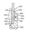
図34には、図4の圧縮機及び図32の圧縮機のいくつかの特徴を組合せてある構造の密閉型圧縮機880を示してある。圧縮機880はプレート884を有する外殻882を備え、プレート884は外殻882の内部を、上方の吐出チャンバ886と吸入圧力の下方領域888とに区画している。下方領域888内に固定配置した主軸受箱890に駆動軸892を回転可能に支持させてあり、駆動軸892は、同様に主軸受箱890上で支持されている旋回スクロール部材894に対し、該スクロール部材894を旋回駆動するように接続されている。非旋回スクロール部材896を、軸線方向に沿い移動可能に主軸受箱890に支持させてある。この非旋回スクロール部材896はその上端に、放射方向の内側及び外側の円筒状突起898,900により仕切られている凹所を有する。フランジ付きの円筒状部材902をプレート884に対し密封的に取付けて突起898,900間に臨ませ、該両突起898,900に対し密封的に係合させることにより上記凹所内を、上方側の分離チャンバ904と下方側の中間圧力付勢チャンバ906とに区画してある。圧縮作用を行いつつある中間圧力の流体ポケットに対し付勢チャンバ906を連通させるための通路907を、非旋回スクロール部材896中に設けてある。円筒状部材902の内部は突起898と協力して、吐出ポート910から吐出逆止弁912を経て吐出チャンバ886に至る吐出ガス通路908を、形成している。
【0073】
図34に示す34A部分を拡大した図35に明瞭に示すように、円筒状部材902中に設けた軸線方向に沿う穴914内にバルブ部材916を、摺動可能に配置してある。このバルブ部材916はその下端近くに径縮小部918を有し、この径小部918はバルブ部材916の図示の第1の位置では分離チャンバ904を通路908内の吐出圧力の流体に対し放射方向の孔920,922を介して流体接続し、該第1の位置から上方向きに変位した第2の位置では分離チャンバ904を領域888内の吸入圧力の流体に対し放射方向の孔922,924を介し流体接続するように働く。バルブ部材916の動きを容易とするために穴914の底部を通路908に連通させる放射方向のベント孔926も、円筒状部材902に設けられている。
【0074】
図34に示すようにバルブ部材916は吐出チャンバ886内を通過して上方へ延び、外殻882外へと突出させてある。このバルブ部材916は外殻882に取付けた適宜のアクチュエータ928に対し接続してあり、アクチュエータ928によって上記した第1の位置と第2の位置間で動かされる。バルブ部材916が外殻882を貫通する部分には管状支承具930を設けてあり、この環状支承具は吐出チャンバ886からの流体漏れを阻止するシールを内装している。アクチュエータ928は、バルブ部材916を上記した第1及び第2の位置間で往復動させる能力を有するものであればどのような型式のものであってもよく、例えばソレノイド又は他の電気式、電子−機械式、機械式、空気圧式又は油圧式の何れの装置であってもよい。所望の場合にはアクチュエータを、外殻882の内部に配置することもできる。
【0075】
圧縮機880の完全負荷状態での運転中は付勢チャンバ906内の中間流体圧力が、通路908内で非旋回スクロール部材896に対し作用する吐出圧力と協力して、非旋回スクロール部材896を軸線方向で移動付勢して旋回スクロール部材894に対し密封的に係合させる。この状態ではバルブ部材916が分離チャンバ904を、孔922,924を介して吸入圧力の領域888に対し連通させる位置をとっている。圧縮機880の負荷解除を得るためにはアクチュエータ928が作動してバルブ部材916を、分離チャンバ904が吐出圧力の通路908に対し孔920,924を介して連通せしめられることとなる位置へと動かし、これによってチャンバ904内が加圧される。分離チャンバ904の該加圧により生じる分離力が非旋回スクロール部材896を移動させて、旋回スクロール部材894との密封係合を解除させ、圧縮機880の負荷解除が得られる。圧縮機880を再負荷するためにはアクチュエータ928が逆方向に作動してバルブ部材916を、分離チャンバ904が吸入圧力の領域888に対し孔922,924を介し連通せしめられてチャンバ904内の圧力が抜かれることとなる初期位置へと戻し、これによって付勢チャンバ906内の中間圧力と通路908内の吐出圧力とに基因する付勢力により非旋回スクロール部材896が、旋回スクロール部材894に対し密封的に係合する位置に戻される。アクチュエータ928を、周期的に、時刻パルス的に作動させることにより圧縮機880の容量を、前述したのと実質的に同一の態様で調整することができる。
【0076】
図36は、図32の実施例及び図33の実施例の変形に係る実施例を示している。本実施例の圧縮機678は軸受箱682に固定支持させてある非旋回スクロール部材680を備え、旋回スクロール部材684が軸線方向で可動であるものに設計されている。圧縮機678は環状の電磁コイルの形の適当な力付与手段686を備えていて、該電磁コイルは、旋回スクロール部材684の下方で該スクロール部材684に対面させて軸受箱682に設けた凹溝688内で、軸受箱682に支持させてある。力付与手段686内に適宜の磁気応動部材690を配置して、旋回スクロール部材684の下面に接当させてある。本実施例では力付与手段686の作動により旋回スクロール部材684に対し上方向きの力が加えられ、それにより該スクロール部材684が非旋回スクロール部材680に対し密封的に係合せしめられる。圧縮機678の負荷解除は力付与手段686を非作動とすることで達成され、該手段686を非作動とすると同手段686により発生される力が消滅し、圧縮中の流体に基因する分離力によって旋回スクロール部材684が軸線方向で動かされて非旋回スクロール部材680との密封係合を解除する。力付与手段686を制御することにより周期的なパルス的負荷及び負荷解除を、前述したのと実質的に同一の態様で簡単に達成できる。
【0077】
電磁力付与手段を利用した圧縮機678について述べたが、同手段を機械式、磁気式、電子−機械式、油圧式、空気圧式、ガス式、又はスプリング式の装置等であってよい他の型式の適当な力付与手段に置換えもよい。
【0078】
以上に説明して来た実施例は全て、両スクロール部材の軸線方向での分離によって圧縮機の負荷解除を得るように構成されている。しかしこの発明に係る圧縮機は、両スクロール翼の翼側面を放射方向で分離させ、両スクロール翼にて形成されている流体ポケット間に漏れ経路を生じさせることによって負荷解除を達成するものにも、構成できる。そのように構成してある数実施例を、図37−45に示し以下で説明する。
【0079】
放射方向での分離により負荷解除を得る圧縮機の一例を図37−40に、符号692で全体を指して図示してある。圧縮機692は概してこれ迄述べて来た圧縮機に類似しており、その外殻694の内部は吐出チャンバ696と吸入圧力の下方領域698とに仕切られている。外殻694内で軸受箱700を固定支持してあって、非旋回スクロール部材702は該軸受箱700に、軸線方向に沿い移動可能に取付け支持され、また旋回スクロール部材704は軸受箱700上で支持され、クランク軸706によって駆動される。非旋回スクロール部材702の上端に中間圧力付勢チャンバ708を設けてあり、該チャンバ708は流体ポケットから通路710を介して中間圧力の流体を供給され、非旋回スクロール部材702を軸線方向で移動付勢して旋回スクロール部材704に対し密封的に係合させる。
【0080】
軸受箱700は周方向で間隔をあけて配置された複数個の実質的に等しいチャンバ712を有し、各チャンバ712内にはピストン714を上下動可能に配置してある。各ピストン714は上方向きに突出するピン716を有し、該ピン716は軸受箱700上面部に形成された穴718を通して、穴718と整列させて非旋回スクロール部材702中に設けられた穴720中へと突入させてある。各穴720内にはスプリング722を、非旋回スクロール部材702に取付けた一端封止の管状バネ受724と各ピン716の上端面との間で挿入設置してあり、該スプリング722はピン716を下方向きに移動付勢する。各ピン716は、小径の上半部726と大径の下半部728とを有する。複数個の該ピン716は、旋回スクロール部材704の外周縁を取巻くように配置されている。軸受箱700の低部には環状のマニホールド729を固定してあり、このマニホールド729によって複数個のチャンバ712の下端が閉鎖されている。マニホールド729は環状の通路731と、この通路731から上方へ延びてそれぞれのチャンバ712に開口する複数個の軸線方向の通路733とを、含んでいる。
【0081】
図38に明瞭に示すようにクランク軸706の偏心したクランクピン730は旋回スクロール部材704に対し、該スクロール部材704に設けたハブ734内に回転可能に配置された駆動ブッシュ732を用いて、接続されている。駆動ブッシュ732は、ほぼ長円形であって一側に平坦面部738を有する穴736を備え、平坦面部738に対し係合可能である平坦面部740を有する上記クランクピン730を穴736内に臨ませ、平坦面部738,740を介して旋回スクロール部材704に駆動力を伝達するように、構成してある。図示のように穴736の寸法は駆動ブッシュ732と旋回スクロール部材704が互いに対し相対的に移動可能であって、それにより旋回スクロール部材704の旋回半径が、両スクロール翼の翼側面同士が互いに密封的に係合することとなる最大値から該翼側面同士が互いから分離することとなる最小値にまで減少し得るように、設定されている。
【0082】
圧縮機692も三方電磁弁742を備えていて、この電磁弁742はマニホールド729の環状通路731に接続してある第1の流体ライン744、吸入ライン748に接続してある第2の流体ライン746、及び吐出ライン752に接続してある第3の流体ライン750を有する。
【0083】
完全負荷状態での運転中に電磁弁742は、各チャンバ712を吸入ライン748に対し、マニホールド729の通路733,731及び流体ライン744,746を介して連通させる位置をとっている。したがって各ピストン714とそれに一体形成してある各ピン716はスプリング722の力で下降した位置に保持され、旋回スクロール部材704はその最大旋回半径で自在に旋回動する。軸線方向で可動の非旋回スクロール部材702が、付勢チャンバ708内の中間流体圧力により移動付勢されて旋回スクロール部材704に対し密封的に係合しているので、圧縮機692は全容量で稼働する。圧縮機692を負荷解除するためには電磁弁742が、マニホールド729の環状通路731を吐出ライン752へと連通させる位置へ作動され、これにより各チャンバ712が吐出圧力の流体によって加圧されて、図40に示すように各ピストン714及びピン716が完全な上昇位置にまで上昇動せしめられる。それぞれのピストン714に対し作用する吐出圧力の流体による力は、旋回スクロール部材704を放射方向の外向きに付勢する力に打克つほど大きくはないので、それぞれのピン716は、旋回スクロール部材704が該ピン716位置を通り過ぎて旋回するにつれて順次、上昇動する。全てのピン716が一旦上昇動し終ると、図39に明瞭に示すように旋回スクロール部材704の外周縁に設けられているアーチ形の切欠き754に対し、ピン716の大径部728が係合することになる(図40参照)。これによって旋回スクロール部材704の旋回半径の最小値にまでの減少が生ぜしめられ、両スクロール翼の翼側面同士がもはや密封的に係合し合わないこととなって、圧縮機が完全に負荷解除される。複数個のピン716は、旋回スクロール部材704の完全な旋回動の間に少なくとも隣合った2個のピンが対応する切欠き754に対し係合することとなるように、周方向で間隔をあけて配置されている。負荷状態での運転を再開すべきときは電磁弁742が、チャンバ712から吸入ライン748に対し通路733,731及び流体ライン744,746を介し圧力を抜く位置へと戻され、これにより各ピン716及びピストン714がスプリング722の力で、ピン716の小径部726が切欠き754に対し放射方向で間隔をあけた関係となる位置へと下降され、旋回スクロール部材704が最大旋回半径での旋回を再開して、全容量での圧縮が再開する。
【0084】
図41は図37−40の実施例の変形例に係る圧縮機756を示しており、本変形例では二方電磁弁758を利用していて、該電磁弁758はチャンバ712に対し接続された流体ライン760、及び吐出ライン752に接続された流体ライン762を有する。また本実施例では各チャンバ712がその下端に、外殻694内の吸入圧力の下方領域698に対し常時連通する通路764を、有する。したがって各チャンバ712は常に、吸入側に連通している。圧縮機756を負荷解除するには電磁弁758を開放して各チャンバ712を、吐出ライン752からの吐出流体圧力に加圧し、それにより各ピストン714を移動付勢して上昇位置とする。図41の圧縮機756の他の部分は図37−40の圧縮機692の対応する部分と実質的に等しく、同一の符号で指してある。圧縮機756の他の作用は、圧縮機692について前述したのと実質的に同一である。
【0085】
図37−40の実施例の他の変形に係る実施例の圧縮機766を、図42,43に示してある。本実施例では前記切欠き754を無くし、それに代えて2個の円形の穴768を、旋回スクロール部材704に設けている。ピン714の小径部726に対する穴768の相対的な直径は、旋回スクロール部材704がその最大旋回半径で旋回しつつあるときピンと穴周壁面間に若干の隙間が存在するように、設定されている。ピン716の大径部728が穴768中へ移動せしめられて図示のように穴728の周壁面に対し係合すると、旋回スクロール部材704の旋回半径が最小値にまで減少され、両スクロール翼の翼側面間での密封が解除される。
【0086】
図42,43の実施例ではまた、前記スプリング722に代えて中間圧力付勢機構を設けており、同機構は非旋回スクロール部材702中に設けた通路770を含む。この通路770は中間圧力付勢チャンバ708を管状部材724内に連通させるもので、このためピン716はその下降位置へと、中間流体圧力によって移動付勢される。他の点で圧縮機766の構成と作用は圧縮機692について述べたのと実質的に等しく、対応する部分は同一の符号で指してある。
【0087】
両スクロール翼の放射方向での分離により負荷解除を得る他の実施例に係るスクロール式圧縮機772を、図44,45に示してある。この圧縮機772の構造は前記圧縮機692の構造に類似していて、その外殻774の内部は仕切り板776により、上方の吐出チャンバ778と吸入圧力の下方領域780とに仕切られている。下方領域780内に主軸受箱を固定設置してあり、この主軸受箱はブッシング786及び締結具788を介して非旋回スクロール部材784を軸線方向に沿い移動可能に支持する第1部材782を含み、この第1部材782上で旋回スクロール部材790が支持されている。第1部材782の下端に主軸受箱の第2部材792を取付けてあり、この第2部材792はクランク軸794を回転可能に支持すると共に、第1部材782及び旋回スクロール部材790と協力して実質的に閉鎖されている空所796を区画形成している。旋回スクロール部材790は円錐面状の外面を有する中心ハブ797を備えており、この中心ハブ797はクランク軸794上の偏心クランクピン798と、駆動ブッシュ800を介して係合するものとされている。クランクピン798及び駆動ブッシュ800は、図38に示した前記クランクピン730及び駆動ブッシュ732と実質的に等しく、旋回スクロール部材790の旋回半径の前述同様の変更、つまり両スクロール翼の翼側面同士が互いに密封的に係合し合うこととなる最大旋回半径と該翼側面が互いから離間することとなる最小旋回半径との間での変更、を許す。
【0088】
非旋回スクロール部材784はその上面に環状凹溝を有し、該凹溝中に浮動シール部材802を配置して中間圧力付勢チャンバ804を区画形成してある。該チャンバ804は吸入及び吐出圧力間の、圧縮されつつある中間圧力の流体を通路806を介して供給され、非旋回スクロール部材784を軸線方向で移動付勢して旋回スクロール部材790に対し密封的に係合させる。浮動シール部材802はその上面で仕切り板776に対し密封的に係合して非旋回スクロール部材784と共に、吐出ポート810から吐出逆止弁812及び仕切り板776中の穴814を経て吐出チャンバ778に至る吐出流体通路808を形成している。
【0089】
空所796内に環状のピストン部材816を上下動可能に配置し、適当なシールを施すことにより空所796の下端に密閉された分離チャンバ818を区画形成してある。主軸受箱第1部材782の放射方向内向きのフランジ部882とピストン部材816に設けた複数個の凹部との間に複数個のスプリング820を配置して、該スプリング820によりピストン部材816を、ハブ797から遠去かる下方向きに移動付勢してある。ピストン部材816は上端部内周面を円錐面826に形成され、この円錐面826は中心ハブ797の相補形状の円錐面状外面に対し係合させるものとされている。
【0090】
三方電磁弁828も設けられ、この電磁弁828は流体ライン830を介し分離チャンバ818に、流体ライン834を介し吸入ライン832に、そして流体ライン838を介し吐出ライン836に、それぞれ接続されている。しかし図示の三方電磁弁828に代えて、チャンバ818を吐出側に対してのみ選択的に接続可能である二方電磁弁を用いることもできる。その場合には図41の実施例について前述したのに類似して、分離チャンバ818の底部から主軸受箱第2部材792を貫通し吸入圧力領域780に開口するブリード孔を設けて、吐出圧力流体の排出を可能とする必要があろう。
【0091】
完全負荷状態での運転中に電磁弁828は、分離チャンバ818を吸入ライン832に対し流体ライン830,834を介して連通させる位置にあり、このため該チャンバ818は実質的に吸入圧力に維持される。スプリング820の作用でピストン部材816は図44に示す下降位置に保持され、この状態で該ピストン部材816の円錐面826は、旋回スクロール部材790の中心ハブ797の円錐面状外面から若干離間している。
【0092】
負荷解除が望まれると電磁弁828が、吐出ライン836を分離チャンバ818に対し流体ライン838,830を介して連通させる位置へと移され、これによって分離チャンバ818が実質的に吐出圧力へと加圧される。このチャンバ818の加圧によって生じる付勢力によりピストン部材816は、スプリング820の付勢力に打克って上方向きに動かされ、その円錐面826が、旋回スクロール部材790の中心ハブ797の円錐状外面に対し係合する。ピストン部材816が引続いて図45に示す位置まで上昇するにつれ、旋回スクロール部材790の旋回半径が減少されて両スクロール翼の翼側面同士がもはや密封係合し合わない状態が得られ、流体の圧縮が止む。圧縮を再開するためには電磁弁828が、分離チャンバ818内の圧力を吸入ライン832に対し流体ライン830,834を介して抜く位置へと移され、これによってスプリング820によりピストン部材816が、図44に示す下降位置へと戻される。
【0093】
ピストン816を下方向きに移動付勢するためスプリング820を設けてある圧縮機772を示したが、或る用途においてはこれらの付勢部材を無くし、ハブ797の円錐面状外面に対するピストン円錐面826の係合によってピストン816に加わる力の軸線方向成分を利用して、旋回スクロール部材790から離間する向きのピストン816の運動を生じさせてもよい点が、理解されるべきである。図44,45の実施例においても電磁弁828は制御モジュールとセンサー(図示せず)を用いて、系条件の変動に対応して周期的に制御されるようにされることは、他の実施例について前述したのと同様である。
【0094】
以上に説明した諸実施例で採用している種々の特徴的構造は、当該実施例のみにおいて利用されるものであると限定的にみなされるべきではなく、他の実施例でもそこで採用している特定の特徴的構造につけ加えるか該構造に代えて利用できるものと、みなされるべきである。例えばいくつかの実施例で外殻上に配置した吐出逆止弁は、他の実施例で吐出ポートに隣接させて設けている吐出逆止弁と置換えもよい。また図19及び図21の実施例について述べた吸入制御モジュールを、他の実施例においても利用することができる。さらに多くの実施例で電磁弁とそれに関連する流体ラインを外殻の外部に配置したが、所望の場合にはそれらの電磁弁及び流体ラインを外殻の内部に配置してよい。
【0095】
これ迄述べて来た各実施例では圧縮機が負荷解除状態にある間、旋回スクロール部材を継続して駆動することとしている。圧縮機の負荷解除時(圧縮作用なし。)に旋回スクロール部材を駆動するのに要求される動力は明らかに、圧縮機が完全に負荷されている状態で旋回スクロール部材を駆動するのに要求される動力よりもかなり小さい。したがって負荷減少状態での稼働期間中にモータ効率を改善することとする追加の制御手段を設けることが、望ましいであろう。
【0096】
そのような制御手段を設けた実施例を、図46に模式的に示してある。電動型圧縮機840は電磁弁842を備え、この電磁弁842は流体ライン846を介して吐出ライン844に、また流体ライン850を介して吸入ライン848に、それぞれ接続され、圧縮機の負荷解除機構を、流体ライン852を介し選択的に吸入ライン又は吐出ラインの何れかに流体連通させるように働く。電磁弁842は制御モジュール854によりライン855を介し、センサー856によって感知された条件に応じて制御することとしてある。したがって図46の系は前述諸実施例を模式的に図解した代表例であり、電磁弁842は図示の三方弁に代えて二方弁とすることもできる。負荷減少状態での稼働中の駆動モータの効率を改善するためモータ制御モジュール858も設けてあり、このモータ制御モジュール858は圧縮機のモータ回路に対しライン860を介し接続され、また制御モジュール854に対しライン862を介し接続されている。モータ制御モジュール858は、圧縮機が負荷解除運転状態におかれていることを指示する、制御モジュール854からの信号に呼応して動作するものとされている。同信号に応じモータ制御モジュール858は1個又は複数個のモータ運転パラメータを変更することによって、負荷減少状態での稼働中のモータの効率を改善する。該運転パラメータはモータ運転効率に対し影響する変更制御可能な因子の何れであってもよく、パラメータ変更には例えば、電圧の減少とかモータ運転キャパシタンスの変更とかが含まれる。制御モジュール854によりモータ制御モジュール858に対し、圧縮機が完全負荷状態で運転されているという信号が与えられると、モータ制御モジュール858は変更した運転パラメータを元に戻し完全負荷運転中のモータ効率を最大とする。
【0097】
前述した圧縮機の負荷解除機構は従来の容量調整方法と対比して、広範囲の容量調整を比較的安価で効率のよい方法で実施し系の全体としての効率を大きく高めるのに、特に適している。しかし例えば凝縮器の入口圧力が低いレベルにあるような場合の運転条件下では、冷媒の過大圧縮を避けるため系容量の減少レベルに合わせて圧縮機の圧縮比を減少させるのが望ましいであろう。
【0098】
図47に示す圧縮機864では、前述の周期的もしくは時限パルスによる負荷解除機構を、圧縮機の圧縮比を減少させるための手段と共に採り入れて、どのような運転条件下でも圧縮機の能力を増して効率を最大限のものとするように図ってある。図47に示す圧縮機864は以下に述べる点を除いて図1の圧縮機10と実質的に同一であり、対応する部分は図1で用いたのと同じ符号で指してある。
【0099】
圧縮機864の非旋回スクロール部材32中には、両スクロール翼間の流体ポケット870,872にそれぞれ開口する1対のポート866,868を形成してある。これらのポート866,868は非旋回スクロール部材32の端板中の通路874に連通させてあり、通路874は非旋回スクロール部材32の外周縁に開口して、吸入圧力にある外殻12内の下方領域876に連通している。ポート866,868の領域876に対する連通を選択的に制御するため、適当なバルブ手段878を設けてある。ポート866,868は、流体ポケット870,872が領域876からの吸入流体の供給を遮断される、つまり密封される、のに先立って該流体ポケット870,872に対し連通し始めるように、配置するのが好ましい。
【0100】
運転中に圧縮機の容量を減らすのが望ましいと判定されると、圧縮機が過大圧縮モードで稼働しているか過小圧縮モードで稼働しているかも、系の作動条件から判定される。過大圧縮モードにあると判定されるとバルブ手段878を開放して、流体ポケット870,872を吸入圧力領域876に対し連通させることにより、初期の容量減少が最も効率的に実施される。つまりバルブ手段878を開放することによってスクロール翼の有効長を、それぞれの流体ポケット870,872が閉鎖されて吸入ガスの供給を遮断されることとなるまで圧縮が開始されないように、減らすのである。ポート866,868が領域876に開口している状態での流体ポケット閉鎖時の該ポケット870,872の容量は、ポート866,868が領域876に開口していない場合よりも小さいので、圧縮比が減少されることになる。ポート866,868を開口させた後にもさらに容量の減少が要求されると、前述したのと同様の態様で圧縮機864の周期的な負荷解除が開始される。
【0101】
初期に圧縮機が過小圧縮モードにあるか過小圧縮モードと過大圧縮モード間の点にあると判定されると、圧縮比を減らすことによっては効率の低下が生じるだけである。したがってこれらの条件下ではバルブ手段878、したがってポート866,868をを閉鎖したままに留めて、圧縮機864の周期的な負荷解除を前述同様の態様で開始する。
【0102】
この方法によりその都度の運転条件がどのようであっても、系の全体としての効率を高いレベルに維持できる。図47は容量調整のための吸入遅延方法を図1の実施例中に採り入れた例を示しているが、前述した何れの実施例と組合せても同方法を利用することができる。また容量調整のための図示の吸入遅延機構は1組のポートによって与えられる単一過程を利用するものであるが、系の運転条件に依存して開放させる複数組のポートによる多段の過程を利用することも可能である。また図示の特定のバルブ及びポート配置は、吸入遅延法により容量調整を達成できる他の多くの配置が存在することからして、単なる例示に過ぎない。公知の吸入遅延法の何れも、図示の配置に代えて利用できる。図46について述べた負荷減少状態でのモータ効率制御機構を、図47の実施例中に採り入れることも可能である。
【0103】
以上に説明して来た本発明の好ましい諸実施例が、前述の長所と特徴を付与するよう十分に工夫されたものであることは明らかであるが、特許請求の範囲の記載を適正に解釈した発明範囲を逸脱することなしに数多くの修正及び変更を加えて本発明を実施可能である点は、容易に理解される通りである。
【図面の簡単な説明】
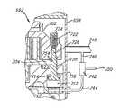
【図1】この発明の一実施例のスクロール式圧縮機を示す縦断面図である。
【図2】この発明の他の実施例のスクロール式圧縮機の上半部を示す縦断面図である。
【図3】図2の圧縮機の上半部を、負荷解除状態で示す縦断面図である。
【図4】この発明のさらに他の実施例のスクロール式圧縮機の上半部を示す縦断面図である。
【図5】図4の一部(鎖線で囲んだ部分)を拡大して、バルブ構造を示す拡大図である。
【図6】この発明の別の実施例のスクロール式圧縮機の上半部を示す縦断面図である。
【図7】圧縮機の負荷解除のために旋回スクロール部材が軸線方向に沿い往復動せしめられる、この発明のさらに別の実施例のスクロール式圧縮機の上半部を示す縦断面図である。
【図8】図7に類似の縦断面図で、他の実施例を示している。
【図9】図7に類似の縦断面図で、さらに他の実施例を示している。
【図10】図7に類似の縦断面図で、別の実施例を示している。
【図11】図7に類似の縦断面図で、さらに別の実施例を示している。
【図12】図7に類似の縦断面図で、他の実施例を示している。
【図13】図7に類似の縦断面図で、さらに他の実施例を示している。
【図14】図7に類似の縦断面図で、別の実施例を示している。
【図15】図7に類似の縦断面図で、さらに別の実施例を示している。
【図16】圧縮機の負荷解除を得るために非旋回スクロール部材が軸線方向に沿い往復動せしめられる、この発明の他の実施例のスクロール式圧縮機の上半部を示す縦断面図である。
【図17】図16に類似の縦断面図で、さらに他の実施例を示している。
【図18】図16に類似の縦断面図で、別の実施例を示している。
【図19】図16に類似の縦断面図で、さらに別の実施例を示している。
【図20】図16に類似の縦断面図で、他の実施例を示している。
【図21】図16に類似の縦断面図で、さらに他の実施例を示している。
【図22】図16に類似の縦断面図で、なお他の実施例を示している。
【図23】両スクロール部材が旋回する、この発明の別の実施例のスクロール式圧縮機の上半部を示す縦断面図である。
【図24】図23に類似の縦断面図で、さらに別の実施例を示している。
【図25】図23に類似の縦断面図で、他の実施例を示している。
【図26】図23の圧縮機に類似の、なお他の実施例の圧縮機を示す縦断面図である。
【図27】図23に類似の縦断面図で、別の実施例を示している。
【図28】図23に類似の縦断面図で、なお別の実施例を示している。
【図29】非旋回スクロール部材が往復動せしめられる、この発明の他の実施例のスクロール式圧縮機の上半部を示す縦断面図である。
【図30】図29に類似の縦断面図で、さらに他の実施例を示している。
【図31】外部の動力源により駆動されるものに構成されている、この発明の別の実施例のスクロール式圧縮機を示す縦断面図である。
【図32】この発明のなお別の実施例のスクロール式圧縮機の上半部を示す縦断面図である。
【図33】図32に類似の縦断面図で、他の実施例を示している。
【図34】図32に類似の縦断面図で、さらに他の実施例を示している。
【図35】図34の34A部を拡大した拡大図で、バルブ構造を示している。
【図36】この発明の別の実施例のスクロール式圧縮機の上半部を示す縦断面図である。
【図37】放射方向での負荷解除を得る、この発明のなお別の実施例のスクロール式圧縮機の上半部を示す縦断面図である。
【図38】図37の38−38線に沿う横断面図で、クランクピンと駆動ブッシュを示している。
【図39】図37の39−39線に沿う横断面図である。
【図40】図37の圧縮機に類似の、他の実施例の圧縮機の一部分を示す縦断面図である。
【図41】図40に類似の縦断面図で、さらに他の実施例を示している。
【図42】図40に類似の縦断面図で、別の実施例を示している。
【図43】図39に類似の横断面図で、図42の圧縮機の一部を示している。
【図44】この発明のさらに別の実施例のスクロール式圧縮機の上半部を示す縦断面図である。
【図45】図44の圧縮機の一部を、負荷解除状態で示す縦断面図である。
【図46】圧縮機が負荷解除状態で運転されている期間中にモータの動力消費量を減少させる、この発明に従った手段を示す模式図である。
【図47】この発明に従って、周期的なスクロール翼分離と吸入遅延との両者により負荷解除を得るようにされたスクロール式圧縮機の上半部を示す縦断面図である。
【符号の説明】
18,476,612,632,706,794,892 クランク軸(駆動軸)
20,144,144a,242,312,342,356,400,482,630,682,700,890 軸受箱
26,146,156,222,268,334,590,634,684,704,790,894 旋回スクロール部材
32,142,182,224,258,296,354,636,680,702,784,896 非旋回スクロール部材
42,172,214,248,290,414,504,568,626,696,778,886 吐出チャンバ
56,260,314,366,428,522,818,904 分離チャンバ
58,206,262,426,484,550,586,642,708,804,906 付勢チャンバ
64,86,192,278,322,368,396,432,492,524 通路
68,162,196,228,270,320,372,386,440,532,594,604,742,758,828,842 電磁弁
72,149,200,234,332,380,388,452,540,610,748,832,848 吸入ライン
76,204,272,330,378,448,536,752,836,844 吐出ライン
78,156,208,226,266,338,430,486,548,560,588,660,710,806,907 通路(孔)
80,672,854 制御モジュール
82,674,856 センサー
104,916 バルブ(部材)
148,148b 圧力チャンバ
158,231 通路
186,520,714,816 ピストン(部材)
404,498 スクロール部材
406,500 スクロール部材
664,928 アクチュエータ
686 力付与手段
858 モータ制御モジュール
866,868 ポート
878 バルブ手段[0001]
[Industrial application fields]
The present invention relates to a scroll type machine provided with a capacity adjusting mechanism, and more particularly to a scroll type compressor.
[0002]
BACKGROUND OF THE INVENTION
Incorporating capacity adjustment mechanisms in air conditioning and refrigeration compressors is often desirable to better accommodate the wide range of load conditions in which the system can be placed. Numerous methods have been used to obtain capacity adjustment, from control of the inlet to return by discharge to the inlet of the discharge gas. The capacity of the scroll compressor is often adjusted by the suction delay method. In this method, when opened, ports for communicating the fluid compression pockets formed between the meshing scroll blades to the intake gas supply side are arranged at various positions, whereby the compression start point of the intake gas is provided. Delay. This capacity adjustment method actually reduces the compression ratio of the compressor. While such a system is effective in reducing compressor capacity, it can only unload a predetermined amount of the compressor, and the amount of unloading depends on the placement of the unloading port along the scroll spiral blades. To do. Although it is possible to obtain a multi-stage load release by providing a large number of ports at various positions, this method is expensive and provides a plurality of separate control mechanisms for controlling the opening and closing of each pair of ports. Additional space is required.
[0003]
The present invention is intended to eliminate such inconveniences and to enable a continuous range of load release from 100 percent to full capacity to substantially zero capacity using only a single control mechanism. It is also an object of the present invention to maximize the operating efficiency of the compressor and / or cooling system for any desired degree of compressor load release.
[0004]
SUMMARY OF THE INVENTION
The present invention achieves compressor unloading by periodically separating the scroll members in the axial or radial direction for a predetermined time during the compressor operating cycle. In particular, the present invention moves one scroll member in the direction of the time pulse relative to the other scroll member along the axial direction or radial direction, thereby causing both spirals to cross the blade tips or side surfaces of both scroll spiral blades. Periodically, a leakage path from the high pressure side fluid compression pocket between the blades to the low pressure side fluid compression pocket and finally to the suction side is created. By controlling the relative time between sealing and unsealing of the tip or side of the scroll spiral wing, virtually any degree of unloading is achieved using a single control system it can. Also, by sensing various conditions in the cooling system, the compressor load time and load release time for each cycle can be selected to maximize the overall system efficiency for a given capacity compressor. it can. For example, if it is desirable to operate the compressor at 50% capacity, the compressors are alternately loaded for 5 seconds and unloaded (no load) for 5 seconds or loaded for 7 seconds and 7 seconds. Only the load is released. This makes it possible to obtain higher efficiency for each specific operating condition.
[0005]
Although the present invention can be implemented in a very wide variety of modes as shown in the embodiments described later, in the scroll compressor according to the present invention, one scroll member is relative to the other scroll member along the axial direction or radial direction. In particular, the compressor is reciprocated so as to obtain the load release or capacity adjustment of the compressor in the entire range. Providing a highly efficient system at a relatively low cost by enabling capacity adjustment in the entire range using a single control system and by enabling selection of load and load release operation time it can.
[0006]
In order to further improve the system efficiency in a specific application, it may be desirable to combine the above-described time pulse-like unloading method with the inhalation delay method described above as the prior art. For example, if the system pressure immediately downstream of the discharge valve is lower than the design full load level, the pressure of the compressed fluid when discharged from the fluid compression pocket is too high due to the compression ratio of the compressor. A state called over-compression occurs. The most effective way to reduce the capacity in this state is to reduce the compression ratio of the compressor, and thus the pressure of the compressed fluid exiting the fluid compression pocket, only if it is equal to or slightly equal to the system pressure immediately downstream of the discharge valve. It is to reduce to a high value and eliminate work loss due to excessive compression. However, once it is instructed to further reduce the capacity according to the system conditions after the over-compressed state is lost, using the time-pulse capacity adjustment method is a state called under-compression, That is, it is more effective because it avoids the situation where the pressure of the compressed fluid when discharged from the fluid compression pocket becomes lower than the pressure immediately downstream of the discharge valve. Therefore, the present invention also includes a machine that combines a time pulse-like capacity adjustment mechanism and a capacity adjustment mechanism by inhalation delay, and the efficiency of the system in which the above-described state is highly likely to occur by such a combination, This can be achieved by increasing only one of the capacity adjustment mechanisms.
[0007]
The present invention also provides a machine incorporating a controller for the motor that controls various operating parameters of the motor so as to improve the motor operating efficiency during the period when the motor load is reduced by releasing the compressor load. To do.
[0008]
Other features and advantages of the present invention can be clearly understood from the following description with reference to the accompanying drawings.
[0009]
【Example】
In FIG. 1, a hermetic scroll compressor according to the present invention is indicated by the
[0010]
The
[0011]
A
[0012]
As the orbiting
[0013]
The
[0014]
As will be described later, the
[0015]
The
[0016]
In order to release the load of the
[0017]
The
[0018]
2 and 3 show a
[0019]
FIGS. 4 and 5 show a
[0020]
A
[0021]
In the state shown in FIGS. 4 and 5, both the
[0022]
FIG. 6 shows a modified embodiment similar to the embodiment of FIGS. 4 and 5, in which a
[0023]
Although the embodiment described above relates to the load releasing structure that moves the non-orbiting scroll member so as to be separated from the orbiting scroll member in the axial direction, the same principle can be applied to the orbiting scroll member. Figures 7-15 each relate to such an embodiment.
[0024]
The
[0025]
During operation of the compressor, the
[0026]
FIG. 8 shows a compressor 140a according to a modification of that of FIG. 7. In this modification, a plurality of
[0027]
FIG. 9 shows a
[0028]
The
[0029]
In the embodiment shown in FIG. 11, an
[0030]
Under normal full load operating conditions, the
[0031]
The
[0032]
Similarly, the
[0033]
FIG. 14 shows a
[0034]
The
[0035]
FIG. 16 shows a
[0036]
A two-
[0037]
FIG. 17 shows a compressor 244a according to a modification of the
[0038]
FIG. 18 shows a
[0039]
An
[0040]
When the
[0041]
A
[0042]
A
[0043]
The
[0044]
FIG. 22 shows a
[0045]
Under normal full load operation, the
[0046]
The present invention is also suitable for application to a double-rotating (double-scrolling orbiting) scroll compressor. Several examples of a twin-rotation scroll compressor are shown in FIGS. 23-28.
[0047]
FIG. 23 shows a double-
[0048]
A
[0049]
An
[0050]
When the
[0051]
FIG. 24 shows a twin-
[0052]
Another embodiment of a twin-
[0053]
A twin-
[0054]
The
[0055]
The operation of the
[0056]
FIG. 27 shows a twin-
[0057]
The
[0058]
During fully loaded operation, the
[0059]
FIG. 28 shows a twin-
[0060]
A
[0061]
A
[0062]
In the embodiment of FIG. 30, during operation in the full load state, the
[0063]
Although the embodiments described so far relate to a hermetic electric compressor, the present invention can also be applied to a compressor that employs an external drive, such as a compressor for an air conditioning system of an automobile. When the present invention is used in such an environment, it is possible to eliminate expensive clutch systems that are normally used in today's air conditioning systems.
[0064]
FIG. 31 shows a
[0065]
A
[0066]
During operation, the external power source continuously drives the
[0067]
While the embodiments described above have utilized compressed fluid to obtain compressor unloading, the invention also provides axial direction of one or both of the two scroll members. Another type of force generating means that causes movement may be used to achieve unloading of the compressor. Figures 32-34 each illustrate such an embodiment.
[0068]
The
[0069]
In this embodiment, a
[0070]
During operation in the full load state, as described above, the intermediate pressure fluid in the
[0071]
FIG. 33 shows a
[0072]
FIG. 34 shows a
[0073]
As clearly shown in FIG. 35 in which the
[0074]
As shown in FIG. 34, the
[0075]
During operation of the
[0076]
FIG. 36 shows an embodiment according to a modification of the embodiment of FIG. 32 and the embodiment of FIG. The
[0077]
Although the
[0078]
All of the embodiments described above are configured to release the compressor load by separating the scroll members in the axial direction. However, the compressor according to the present invention also achieves load release by separating the blade side surfaces of both scroll blades in the radial direction and creating a leakage path between the fluid pockets formed by both scroll blades. Can be configured. Several examples of such configurations are shown in FIGS. 37-45 and described below.
[0079]
An example of a compressor that obtains a load release by separation in the radial direction is shown generally in FIG. The
[0080]
The bearing
[0081]
As clearly shown in FIG. 38, the eccentric crank
[0082]
The
[0083]
During operation in the full load state, the
[0084]
FIG. 41 shows a
[0085]
An
[0086]
42 and 43, an intermediate pressure biasing mechanism is provided in place of the
[0087]
44 and 45 show a
[0088]
The
[0089]
An
[0090]
A three-
[0091]
During operation at full load,
[0092]
When unloading is desired, the
[0093]
While
[0094]
The various characteristic structures employed in the embodiments described above should not be considered as being limited to those used only in the embodiments, but are employed in other embodiments as well. It should be considered that it can be used in addition to or in place of a particular characteristic structure. For example, the discharge check valve disposed on the outer shell in some embodiments may be replaced with a discharge check valve provided adjacent to the discharge port in other embodiments. The inhalation control module described with respect to the embodiments of FIGS. 19 and 21 can also be used in other embodiments. In many embodiments, the solenoid valves and associated fluid lines are located outside the outer shell, but the solenoid valves and fluid lines may be located within the outer shell if desired.
[0095]
In each of the embodiments described so far, the orbiting scroll member is continuously driven while the compressor is in a load release state. The power required to drive the orbiting scroll member when the compressor is unloaded (no compression action) is apparently required to drive the orbiting scroll member with the compressor fully loaded. It is much smaller than the power. It would therefore be desirable to provide additional control means that would improve motor efficiency during operation in reduced load conditions.
[0096]
An embodiment provided with such a control means is schematically shown in FIG. The
[0097]
The compressor load release mechanism described above is particularly suitable for greatly increasing the overall efficiency of the system by carrying out a wide range of capacity adjustments in a relatively inexpensive and efficient manner, in contrast to conventional capacity adjustment methods. Yes. However, under operating conditions such as when the condenser inlet pressure is at a low level, it may be desirable to reduce the compressor compression ratio to the system capacity reduction level to avoid excessive refrigerant compression. .
[0098]
The
[0099]
A pair of
[0100]
If it is determined that it is desirable to reduce the capacity of the compressor during operation, whether the compressor is operating in the overcompression mode or the undercompression mode is also determined from the operating conditions of the system. If it is determined that the compression mode is in the over-compression mode, the valve means 878 is opened to allow the
[0101]
If it is initially determined that the compressor is in the under-compression mode or at a point between the under-compression mode and the over-compression mode, reducing the compression ratio will only cause a reduction in efficiency. Therefore, under these conditions, the valve means 878, and thus the
[0102]
By this method, the efficiency of the entire system can be maintained at a high level regardless of the operating conditions in each case. FIG. 47 shows an example in which the suction delay method for volume adjustment is adopted in the embodiment of FIG. 1, but the same method can be used in combination with any of the embodiments described above. The suction delay mechanism shown in the figure for capacity adjustment uses a single process given by a set of ports, but uses a multistage process with multiple sets of ports that are opened depending on the operating conditions of the system. It is also possible to do. Also, the particular valve and port arrangements shown are merely exemplary because there are many other arrangements that can achieve volume adjustment by the inhalation delay method. Any known inhalation delay method can be used in place of the illustrated arrangement. The motor efficiency control mechanism in the reduced load state described with reference to FIG. 46 can be adopted in the embodiment of FIG.
[0103]
The preferred embodiments of the present invention described above are clearly devised to give the advantages and features described above, but the claims are properly interpreted. It will be readily appreciated that the present invention can be practiced with numerous modifications and alterations without departing from the scope of the invention as set forth.
[Brief description of the drawings]
FIG. 1 is a longitudinal sectional view showing a scroll compressor according to an embodiment of the present invention.
FIG. 2 is a longitudinal sectional view showing an upper half portion of a scroll compressor according to another embodiment of the present invention.
FIG. 3 is a longitudinal sectional view showing an upper half portion of the compressor of FIG. 2 in a load release state.
FIG. 4 is a longitudinal sectional view showing an upper half portion of a scroll compressor according to still another embodiment of the present invention.
5 is an enlarged view showing a valve structure by enlarging a part of FIG. 4 (a part surrounded by a chain line).
FIG. 6 is a longitudinal sectional view showing an upper half portion of a scroll compressor according to another embodiment of the present invention.
FIG. 7 is a longitudinal sectional view showing an upper half portion of a scroll compressor according to still another embodiment of the present invention in which the orbiting scroll member is reciprocated along the axial direction for releasing the load of the compressor.
FIG. 8 is a longitudinal sectional view similar to FIG. 7, showing another embodiment.
FIG. 9 is a longitudinal sectional view similar to FIG. 7, showing still another embodiment.
FIG. 10 is a longitudinal sectional view similar to FIG. 7 showing another embodiment.
FIG. 11 is a longitudinal sectional view similar to FIG. 7, showing yet another embodiment.
FIG. 12 is a longitudinal sectional view similar to FIG. 7, showing another embodiment.
FIG. 13 is a longitudinal sectional view similar to FIG. 7, showing still another embodiment.
FIG. 14 is a longitudinal sectional view similar to FIG. 7 showing another embodiment.
FIG. 15 is a longitudinal sectional view similar to FIG. 7, showing yet another embodiment.
FIG. 16 is a longitudinal sectional view showing the upper half of a scroll compressor according to another embodiment of the present invention in which the non-orbiting scroll member is reciprocated along the axial direction in order to obtain the load release of the compressor. .
FIG. 17 is a longitudinal sectional view similar to FIG. 16, showing still another embodiment.
FIG. 18 is a longitudinal sectional view similar to FIG. 16, showing another embodiment.
FIG. 19 is a longitudinal sectional view similar to FIG. 16, showing a further embodiment.
FIG. 20 is a longitudinal sectional view similar to FIG. 16, showing another embodiment.
FIG. 21 is a longitudinal sectional view similar to FIG. 16, showing still another embodiment.
FIG. 22 is a longitudinal sectional view similar to FIG. 16, showing still another embodiment.
FIG. 23 is a longitudinal sectional view showing the upper half of a scroll compressor according to another embodiment of the present invention in which both scroll members are revolving.
FIG. 24 is a longitudinal sectional view similar to FIG. 23, showing yet another embodiment.
FIG. 25 is a longitudinal sectional view similar to FIG. 23, showing another embodiment.
FIG. 26 is a longitudinal sectional view showing a compressor of still another embodiment similar to the compressor of FIG.
FIG. 27 is a longitudinal sectional view similar to FIG. 23 showing another embodiment.
FIG. 28 is a longitudinal sectional view similar to FIG. 23 showing yet another embodiment.
FIG. 29 is a longitudinal sectional view showing an upper half portion of a scroll compressor according to another embodiment of the present invention in which a non-orbiting scroll member is reciprocated.
FIG. 30 is a longitudinal sectional view similar to FIG. 29 and shows yet another embodiment.
FIG. 31 is a longitudinal sectional view showing a scroll compressor according to another embodiment of the present invention, which is configured to be driven by an external power source.
FIG. 32 is a longitudinal sectional view showing the upper half of the scroll compressor according to still another embodiment of the present invention.
FIG. 33 is a longitudinal sectional view similar to FIG. 32 showing another embodiment.
FIG. 34 is a longitudinal sectional view similar to FIG. 32, showing still another embodiment.
FIG. 35 is an enlarged view of a
FIG. 36 is a longitudinal sectional view showing the upper half of the scroll compressor according to another embodiment of the present invention.
FIG. 37 is a longitudinal sectional view showing an upper half of a scroll compressor according to still another embodiment of the present invention, which obtains a load release in the radial direction.
38 is a transverse sectional view taken along line 38-38 in FIG. 37, showing a crankpin and a drive bushing.
FIG. 39 is a transverse sectional view taken along line 39-39 in FIG.
FIG. 40 is a longitudinal sectional view showing a part of another example compressor similar to the compressor of FIG. 37;
FIG. 41 is a longitudinal sectional view similar to FIG. 40, showing still another embodiment.
FIG. 42 is a longitudinal sectional view similar to FIG. 40 showing another embodiment.
43 is a cross-sectional view similar to FIG. 39, showing a portion of the compressor of FIG.
FIG. 44 is a longitudinal sectional view showing an upper half portion of a scroll compressor according to still another embodiment of the present invention.
45 is a longitudinal sectional view showing a part of the compressor of FIG. 44 in a load release state.
FIG. 46 is a schematic diagram showing means according to the present invention for reducing the power consumption of a motor during a period when the compressor is operating in a load-released state.
FIG. 47 is a longitudinal sectional view showing the upper half of the scroll compressor adapted to obtain a load release by both periodic scroll blade separation and suction delay according to the present invention.
[Explanation of symbols]
18,476,612,632,706,794,892 Crankshaft (drive shaft)
20,144,144a, 242,312,342,356,400,482,630,682,700,890 Bearing box
26,146,156,222,268,334,590,634,684,704,790,894 orbiting scroll member
32,142,182,224,258,296,354,636,680,702,784,896 non-orbiting scroll member
42,172,214,248,290,414,504,568,626,696,778,886 Discharge chamber
56, 260, 314, 366, 428, 522, 818, 904 separation chamber
58,206,262,426,484,550,586,642,708,804,906 biasing chamber
64, 86, 192, 278, 322, 368, 396, 432, 492, 524 passage
68,162,196,228,270,320,372,386,440,532,594,604,742,758,828,842 Solenoid valve
72,149,200,234,332,380,388,452,540,610,748,832,848 inhalation line
76, 204, 272, 330, 378, 448, 536, 752, 836, 844 Discharge line
78,156,208,226,266,338,430,486,548,560,588,660,710,806,907 passage (hole)
80,672,854 control module
82,674,856 sensors
104,916 Valve (member)
148, 148b pressure chamber
158, 231 passage
186, 520, 714, 816 Piston (member)
404,498 scroll member
406,500 scroll member
664,928 Actuator
686 Force imparting means
858 Motor control module
866,868 ports
878 Valve means
Claims (76)
Translated fromJapanese第1のスクロール部材に対して相対的な旋回運動を行うように設置された第2のスクロール部材と、
第1又は第2のスクロール部材に配置された第1及び第2のチャンバとを備え、
第2のスクロール部材において、第1の関係位置の時に第1又は第2のチャンバへの流体連通を普遍的に阻止して第1のスクロール部材との密封係合が形成され、且つ第2の関係位置の時に第1又は第2チャンバへ流体連通させて前記密封係合が解除され、さらに
第1及び第2の螺旋翼がその間に複数個の可動の流体ポケットを形成するように、第1及び第2のスクロール部材間の相対旋回運動のために第1及び第2のスクロール部材を支持する固定支持構造体と、
前記構造体に連結され且つ第1及び第2のチャンバ間の密封を選択的に解除するように設定され、両スクロール部材を第1及び第2の関係位置間で相対移動させるように作動可能であることにより、機械の容量を調整可能とする時刻パルス作動機構と、
を備えるスクロール式機械。A first scroll member;
A second scroll member installed to perform a relative turning motion with respect to the first scroll member;
Firstand second chambers disposed on the first or second scroll member,
In a second scroll member,sealing engagement with thefirstscroll member is formedby a fluidcommunication to the firstor second chamberuniversally blocked when the first relationshipposition, and the secondwherein the sealing engagement is released by fluid communicationto the firstor the second chamber when the relationshipposition, further
Supporting the first and second scroll members for relative pivoting motion between the first and second scroll memberssuch that the first and second spiral wings form a plurality of movable fluid pockets therebetween. A fixed support structure to
Connected to the structure and configured to selectively releasethe sealbetween the first and second chambersand operable to move the scroll members relative to each other between the first and second relationship positions. A time pulse actuation mechanism thatallows the capacity of the machine to be adjusted ,
Scrolling machine with
前記チャンバ内に配置され且つ時刻パルス的に第1及び第2の関係位置間で周期作動するピストンと、
をさらに備え、
前記第1の関係位置は、第1の大きさを有する前記相対旋回運動の半径によって定められ、前記第2の関係位置は、前記第1の大きさよりも小さい大きさで前記ピストンによって限定された前記相対旋回運動の半径によって定められ、前記相対旋回運動の前記限定された半径が、前記可動の流体ポケット間に漏れ径路を形成する請求項24記載のスクロール式機械。A bearing box that rotatably supports the drive shaft and supports both scroll members for relative rotational movement between the first and second scroll members, and at least partially defines a chamber;
A piston disposed within the chamber and cyclically operated between the first and second relationship positions in a time pulse manner;
Further comprising
The first relational position is defined by a radius of the relative swivel motion having a first magnitude, and the second relational position is limited by the piston with a magnitude smaller than the first magnitude. 25. The scroll machine of claim 24, defined by a radius of the relative pivoting motion, wherein the limited radius of the relative pivoting motion forms a leakage path between the movable fluid pockets.
前記バルブ及び前記力付与手段の作動を制御するように作用する制御モジュールと、
をさらに備え、
前記制御モジュールは、時刻パルス的に前記第1及び第2の関係位置間で第1及び第2のスクロール部材の前記移動を生じさせる請求項24記載のスクロール式機械。A valve in fluid communication with at least one of the movable fluid pockets and operative to discharge pressure in the pocket to a low pressure region of the compressor;
A control module acting to control the operation of the valve and the force applying means;
Further comprising
25. The scroll machine of claim 24, wherein the control module causes the movement of the first and second scroll members between the first and second related positions in a time pulse manner.
Applications Claiming Priority (2)
| Application Number | Priority Date | Filing Date | Title |
|---|---|---|---|
| US08/486,118 | 1995-06-07 | ||
| US08/486,118US5741120A (en) | 1995-06-07 | 1995-06-07 | Capacity modulated scroll machine |
Related Child Applications (3)
| Application Number | Title | Priority Date | Filing Date |
|---|---|---|---|
| JP2006220812ADivisionJP4486624B2 (en) | 1995-06-07 | 2006-08-14 | Scroll compressor |
| JP2006220805ADivisionJP2006300075A (en) | 1995-06-07 | 2006-08-14 | Scroll compressor |
| JP2006220822ADivisionJP4621179B2 (en) | 1995-06-07 | 2006-08-14 | Scroll compressor |
Publications (2)
| Publication Number | Publication Date |
|---|---|
| JPH08334094A JPH08334094A (en) | 1996-12-17 |
| JP3959437B2true JP3959437B2 (en) | 2007-08-15 |
Family
ID=23930646
Family Applications (4)
| Application Number | Title | Priority Date | Filing Date |
|---|---|---|---|
| JP31002995AExpired - Fee RelatedJP3959437B2 (en) | 1995-06-07 | 1995-11-02 | Scroll type machine with capacity adjustment mechanism |
| JP2006220812AExpired - Fee RelatedJP4486624B2 (en) | 1995-06-07 | 2006-08-14 | Scroll compressor |
| JP2006220805APendingJP2006300075A (en) | 1995-06-07 | 2006-08-14 | Scroll compressor |
| JP2006220822AExpired - LifetimeJP4621179B2 (en) | 1995-06-07 | 2006-08-14 | Scroll compressor |
Family Applications After (3)
| Application Number | Title | Priority Date | Filing Date |
|---|---|---|---|
| JP2006220812AExpired - Fee RelatedJP4486624B2 (en) | 1995-06-07 | 2006-08-14 | Scroll compressor |
| JP2006220805APendingJP2006300075A (en) | 1995-06-07 | 2006-08-14 | Scroll compressor |
| JP2006220822AExpired - LifetimeJP4621179B2 (en) | 1995-06-07 | 2006-08-14 | Scroll compressor |
Country Status (9)
| Country | Link |
|---|---|
| US (4) | US5741120A (en) |
| EP (3) | EP0747597B1 (en) |
| JP (4) | JP3959437B2 (en) |
| KR (1) | KR100303943B1 (en) |
| CN (6) | CN100453814C (en) |
| DE (2) | DE69536150D1 (en) |
| ES (3) | ES2362965T3 (en) |
| IN (2) | IN188063B (en) |
| TW (1) | TW318875B (en) |
Families Citing this family (167)
| Publication number | Priority date | Publication date | Assignee | Title |
|---|---|---|---|---|
| US5741120A (en)* | 1995-06-07 | 1998-04-21 | Copeland Corporation | Capacity modulated scroll machine |
| US6047557A (en) | 1995-06-07 | 2000-04-11 | Copeland Corporation | Adaptive control for a refrigeration system using pulse width modulated duty cycle scroll compressor |
| US5678985A (en)* | 1995-12-19 | 1997-10-21 | Copeland Corporation | Scroll machine with capacity modulation |
| AU762564B2 (en)* | 1997-09-29 | 2003-06-26 | Emerson Climate Technologies, Inc. | An adaptive control for a refrigeration system |
| US6206652B1 (en) | 1998-08-25 | 2001-03-27 | Copeland Corporation | Compressor capacity modulation |
| US6123517A (en)* | 1997-11-24 | 2000-09-26 | Copeland Corporation | Scroll machine with capacity modulation |
| US6047556A (en) | 1997-12-08 | 2000-04-11 | Carrier Corporation | Pulsed flow for capacity control |
| JP2000088376A (en)* | 1998-09-18 | 2000-03-31 | Hitachi Ltd | Heat pump equipment |
| US6176686B1 (en) | 1999-02-19 | 2001-01-23 | Copeland Corporation | Scroll machine with capacity modulation |
| JP2000291557A (en)* | 1999-04-07 | 2000-10-17 | Sanden Corp | Electric compressor |
| US6220839B1 (en) | 1999-07-07 | 2001-04-24 | Copeland Corporation | Scroll compressor discharge muffler |
| US6505475B1 (en) | 1999-08-20 | 2003-01-14 | Hudson Technologies Inc. | Method and apparatus for measuring and improving efficiency in refrigeration systems |
| US6213731B1 (en)* | 1999-09-21 | 2001-04-10 | Copeland Corporation | Compressor pulse width modulation |
| AU2003252946B2 (en)* | 1999-09-21 | 2006-04-27 | Emerson Climate Technologies, Inc. | Compressor pulse width modulation |
| US6175208B1 (en) | 1999-10-01 | 2001-01-16 | Emerson Electric Co. | High efficiency permanent split capacitor motor for driving a compressor |
| US6300698B1 (en) | 1999-10-22 | 2001-10-09 | Emerson Electric Co. | Hermetic compressor and an electrical connector therefor |
| JP4729773B2 (en)* | 1999-12-06 | 2011-07-20 | ダイキン工業株式会社 | Scroll compressor |
| US6302654B1 (en)* | 2000-02-29 | 2001-10-16 | Copeland Corporation | Compressor with control and protection system |
| US6769264B2 (en) | 2000-06-07 | 2004-08-03 | Samsung Electronics Co., Ltd. | Control system of degree of superheat of air conditioner and control method thereof |
| KR100395918B1 (en)* | 2000-06-07 | 2003-08-27 | 삼성전자주식회사 | Air conditioner control system and control method thereof |
| AU2410601A (en) | 2000-06-07 | 2001-12-17 | Samsung Electronics Co., Ltd. | System for controlling starting of air conditioner and control method thereof |
| EP1287299A4 (en)* | 2000-06-07 | 2007-08-01 | Samsung Electronics Co Ltd | CONTROL SYSTEM OF AN AIR-CONDITIONING SYSTEM AND RELATED METHOD |
| KR100403023B1 (en)* | 2000-06-09 | 2003-10-23 | 삼성전자주식회사 | Outdoor fan control system of air conditioner and control method thereof |
| JP2002070743A (en) | 2000-08-29 | 2002-03-08 | Sanden Corp | Motor-driven compressor for refrigerant compression |
| JP3976512B2 (en) | 2000-09-29 | 2007-09-19 | サンデン株式会社 | Electric compressor for refrigerant compression |
| US6412293B1 (en)* | 2000-10-11 | 2002-07-02 | Copeland Corporation | Scroll machine with continuous capacity modulation |
| JP4073622B2 (en) | 2000-12-18 | 2008-04-09 | サンデン株式会社 | Electric compressor |
| JP4597358B2 (en) | 2000-12-22 | 2010-12-15 | 株式会社日本自動車部品総合研究所 | Scroll compressor |
| JP2002199773A (en) | 2000-12-27 | 2002-07-12 | Sanden Corp | Drive control method for compressor motor and inverter for driving compressor |
| KR100384511B1 (en)* | 2001-02-13 | 2003-05-22 | 삼성전자주식회사 | Air conditioner control system and control method thereof |
| US6672846B2 (en)* | 2001-04-25 | 2004-01-06 | Copeland Corporation | Capacity modulation for plural compressors |
| US6892546B2 (en) | 2001-05-03 | 2005-05-17 | Emerson Retail Services, Inc. | System for remote refrigeration monitoring and diagnostics |
| US6668240B2 (en)* | 2001-05-03 | 2003-12-23 | Emerson Retail Services Inc. | Food quality and safety model for refrigerated food |
| US6551069B2 (en) | 2001-06-11 | 2003-04-22 | Bristol Compressors, Inc. | Compressor with a capacity modulation system utilizing a re-expansion chamber |
| JP2003021084A (en)* | 2001-07-03 | 2003-01-24 | Nippon Soken Inc | Scroll type compressor |
| USD466523S1 (en) | 2001-08-10 | 2002-12-03 | Sanden Corporation | Motor-driven compressor |
| JP2003148343A (en) | 2001-11-08 | 2003-05-21 | Sanden Corp | Motor-driven compressor |
| US6695600B2 (en)* | 2002-05-28 | 2004-02-24 | Lg Electronics Inc. | Scroll compressor |
| WO2004027324A2 (en)* | 2002-09-18 | 2004-04-01 | Igc-Polycold Systems, Inc. | Very low temperature refrigeration system having a scroll compressor with liquid injection |
| DE10248926B4 (en)* | 2002-10-15 | 2004-11-11 | Bitzer Kühlmaschinenbau Gmbh | compressor |
| US6889173B2 (en) | 2002-10-31 | 2005-05-03 | Emerson Retail Services Inc. | System for monitoring optimal equipment operating parameters |
| USD487473S1 (en) | 2002-11-10 | 2004-03-09 | Sanden Corporation | Motor-driven compressor |
| US8463441B2 (en) | 2002-12-09 | 2013-06-11 | Hudson Technologies, Inc. | Method and apparatus for optimizing refrigeration systems |
| JP2004270614A (en)* | 2003-03-11 | 2004-09-30 | Sanden Corp | Electric compressor |
| JP4706892B2 (en)* | 2003-06-30 | 2011-06-22 | 株式会社リッチストーン | Scroll fluid machinery |
| DE602004021821D1 (en)* | 2003-08-25 | 2009-08-13 | Computer Process Controls Inc | COOLING CONTROL SYSTEM |
| JP2005155568A (en)* | 2003-11-28 | 2005-06-16 | Daikin Ind Ltd | Scroll fluid machinery |
| JP2005167492A (en)* | 2003-12-01 | 2005-06-23 | Fujitsu Ltd | Printing method, printing system, printing apparatus, binarized dither matrix pattern, printing program, and computer-readable recording medium recording the program |
| JP4461798B2 (en)* | 2003-12-19 | 2010-05-12 | ダイキン工業株式会社 | Scroll compressor |
| JP4622242B2 (en)* | 2003-12-19 | 2011-02-02 | ダイキン工業株式会社 | Scroll compressor |
| US7070401B2 (en)* | 2004-03-15 | 2006-07-04 | Copeland Corporation | Scroll machine with stepped sleeve guide |
| US7032400B2 (en) | 2004-03-29 | 2006-04-25 | Hussmann Corporation | Refrigeration unit having a linear compressor |
| US7412842B2 (en)* | 2004-04-27 | 2008-08-19 | Emerson Climate Technologies, Inc. | Compressor diagnostic and protection system |
| JP4457789B2 (en)* | 2004-07-15 | 2010-04-28 | パナソニック株式会社 | Hermetic electric compressor |
| US7275377B2 (en) | 2004-08-11 | 2007-10-02 | Lawrence Kates | Method and apparatus for monitoring refrigerant-cycle systems |
| ATE553422T1 (en)* | 2005-02-21 | 2012-04-15 | Computer Process Controls Inc | CONTROL AND MONITORING SYSTEM FOR COMPANIES |
| US20060228243A1 (en)* | 2005-04-08 | 2006-10-12 | Scroll Technologies | Discharge valve structures for a scroll compressor having a separator plate |
| US8036853B2 (en)* | 2005-04-26 | 2011-10-11 | Emerson Climate Technologies, Inc. | Compressor memory system and method |
| US7862312B2 (en)* | 2005-05-02 | 2011-01-04 | Tecumseh Products Company | Suction baffle for scroll compressors |
| US8156751B2 (en)* | 2005-05-24 | 2012-04-17 | Emerson Climate Technologies, Inc. | Control and protection system for a variable capacity compressor |
| US7815423B2 (en)* | 2005-07-29 | 2010-10-19 | Emerson Climate Technologies, Inc. | Compressor with fluid injection system |
| US7752854B2 (en)* | 2005-10-21 | 2010-07-13 | Emerson Retail Services, Inc. | Monitoring a condenser in a refrigeration system |
| US7596959B2 (en) | 2005-10-21 | 2009-10-06 | Emerson Retail Services, Inc. | Monitoring compressor performance in a refrigeration system |
| US20070089435A1 (en)* | 2005-10-21 | 2007-04-26 | Abtar Singh | Predicting maintenance in a refrigeration system |
| US7594407B2 (en) | 2005-10-21 | 2009-09-29 | Emerson Climate Technologies, Inc. | Monitoring refrigerant in a refrigeration system |
| US7752853B2 (en) | 2005-10-21 | 2010-07-13 | Emerson Retail Services, Inc. | Monitoring refrigerant in a refrigeration system |
| US20070089436A1 (en)* | 2005-10-21 | 2007-04-26 | Abtar Singh | Monitoring refrigerant in a refrigeration system |
| US7665315B2 (en)* | 2005-10-21 | 2010-02-23 | Emerson Retail Services, Inc. | Proofing a refrigeration system operating state |
| US20070093732A1 (en)* | 2005-10-26 | 2007-04-26 | David Venturi | Vibroacoustic sound therapeutic system and method |
| US20070092390A1 (en) | 2005-10-26 | 2007-04-26 | Copeland Corporation | Scroll compressor |
| US8590325B2 (en) | 2006-07-19 | 2013-11-26 | Emerson Climate Technologies, Inc. | Protection and diagnostic module for a refrigeration system |
| US20080216494A1 (en) | 2006-09-07 | 2008-09-11 | Pham Hung M | Compressor data module |
| CN100453816C (en)* | 2006-09-22 | 2009-01-21 | 南京奥特佳冷机有限公司 | Whirl type compressor used displacement variable control device |
| US7547202B2 (en) | 2006-12-08 | 2009-06-16 | Emerson Climate Technologies, Inc. | Scroll compressor with capacity modulation |
| WO2008100261A2 (en)* | 2007-02-15 | 2008-08-21 | Carrier Corporation | Pulse width modulation with reduced suction pressure to improve efficiency |
| US7717687B2 (en)* | 2007-03-23 | 2010-05-18 | Emerson Climate Technologies, Inc. | Scroll compressor with compliant retainer |
| US8485789B2 (en)* | 2007-05-18 | 2013-07-16 | Emerson Climate Technologies, Inc. | Capacity modulated scroll compressor system and method |
| US8157538B2 (en)* | 2007-07-23 | 2012-04-17 | Emerson Climate Technologies, Inc. | Capacity modulation system for compressor and method |
| US20090037142A1 (en) | 2007-07-30 | 2009-02-05 | Lawrence Kates | Portable method and apparatus for monitoring refrigerant-cycle systems |
| US8393169B2 (en) | 2007-09-19 | 2013-03-12 | Emerson Climate Technologies, Inc. | Refrigeration monitoring system and method |
| US7997883B2 (en)* | 2007-10-12 | 2011-08-16 | Emerson Climate Technologies, Inc. | Scroll compressor with scroll deflection compensation |
| WO2009055009A2 (en) | 2007-10-24 | 2009-04-30 | Emerson Climate Technologies, Inc. | Scroll compressor for carbon dioxide refrigerant |
| US9140728B2 (en)* | 2007-11-02 | 2015-09-22 | Emerson Climate Technologies, Inc. | Compressor sensor module |
| US8160827B2 (en)* | 2007-11-02 | 2012-04-17 | Emerson Climate Technologies, Inc. | Compressor sensor module |
| US7686599B2 (en)* | 2007-12-13 | 2010-03-30 | Scroll Technologies | Scroll compressor with device to limit orbit radius |
| EP2250374B1 (en)* | 2008-01-16 | 2021-05-26 | Emerson Climate Technologies, Inc. | Scroll machine |
| US7993117B2 (en)* | 2008-01-17 | 2011-08-09 | Bitzer Scroll Inc. | Scroll compressor and baffle for same |
| WO2009140372A1 (en)* | 2008-05-14 | 2009-11-19 | Carrier Corporation | Transport refrigeration system and method of operation |
| US7972125B2 (en) | 2008-05-30 | 2011-07-05 | Emerson Climate Technologies, Inc. | Compressor having output adjustment assembly including piston actuation |
| CN102089524B (en)* | 2008-05-30 | 2014-09-03 | 艾默生环境优化技术有限公司 | Compressor with capacity adjustment system |
| CN102089523B (en)* | 2008-05-30 | 2014-01-08 | 艾默生环境优化技术有限公司 | Compressor with capacity adjustment system |
| BRPI1007407A2 (en)* | 2009-01-27 | 2016-02-16 | Emerson Climate Technologies | unloading system and method for a compressor |
| US7988433B2 (en) | 2009-04-07 | 2011-08-02 | Emerson Climate Technologies, Inc. | Compressor having capacity modulation assembly |
| MX2011012546A (en) | 2009-05-29 | 2012-10-03 | Emerson Retail Services Inc | System and method for monitoring and evaluating equipment operating parameter modifications. |
| US8568118B2 (en)* | 2009-05-29 | 2013-10-29 | Emerson Climate Technologies, Inc. | Compressor having piston assembly |
| US8616014B2 (en)* | 2009-05-29 | 2013-12-31 | Emerson Climate Technologies, Inc. | Compressor having capacity modulation or fluid injection systems |
| US8517703B2 (en)* | 2010-02-23 | 2013-08-27 | Emerson Climate Technologies, Inc. | Compressor including valve assembly |
| CN102395759A (en)* | 2010-04-30 | 2012-03-28 | 松下电器产业株式会社 | Fluid machine and refrigeration cycle apparatus |
| CN102465877B (en)* | 2010-11-04 | 2014-04-02 | 上海汉钟精机股份有限公司 | Scroll-type compressor with improved structure and manufacture method thereof |
| EP2679930A4 (en)* | 2011-02-22 | 2015-04-29 | Hitachi Ltd | REFRIGERATION CYCLE APPARATUS |
| CA2934860C (en) | 2011-02-28 | 2018-07-31 | Emerson Electric Co. | Residential solutions hvac monitoring and diagnosis |
| US10378533B2 (en) | 2011-12-06 | 2019-08-13 | Bitzer Us, Inc. | Control for compressor unloading system |
| DE102011121365B4 (en) | 2011-12-19 | 2013-12-19 | Robert Bosch Gmbh | Spiral compressor with axially displaceable spiral blade |
| US20140331705A1 (en)* | 2011-12-19 | 2014-11-13 | Carrier Corporation | Hydraulic Transport Refrigeration System |
| US8964338B2 (en) | 2012-01-11 | 2015-02-24 | Emerson Climate Technologies, Inc. | System and method for compressor motor protection |
| KR101882713B1 (en)* | 2012-02-27 | 2018-07-27 | 엘지전자 주식회사 | Scroll compressor |
| DE102012104045A1 (en) | 2012-05-09 | 2013-11-14 | Halla Visteon Climate Control Corporation 95 | Refrigerant Scroll Compressor for Automotive Air Conditioning Systems |
| US9039396B2 (en) | 2012-07-03 | 2015-05-26 | Emerson Climate Technologies, Inc. | Piston and scroll compressor assembly |
| US9480177B2 (en) | 2012-07-27 | 2016-10-25 | Emerson Climate Technologies, Inc. | Compressor protection module |
| US9310439B2 (en) | 2012-09-25 | 2016-04-12 | Emerson Climate Technologies, Inc. | Compressor having a control and diagnostic module |
| US9249802B2 (en) | 2012-11-15 | 2016-02-02 | Emerson Climate Technologies, Inc. | Compressor |
| US9651043B2 (en) | 2012-11-15 | 2017-05-16 | Emerson Climate Technologies, Inc. | Compressor valve system and assembly |
| US9435340B2 (en) | 2012-11-30 | 2016-09-06 | Emerson Climate Technologies, Inc. | Scroll compressor with variable volume ratio port in orbiting scroll |
| US9127677B2 (en) | 2012-11-30 | 2015-09-08 | Emerson Climate Technologies, Inc. | Compressor with capacity modulation and variable volume ratio |
| EP2947320B1 (en) | 2013-01-21 | 2021-01-20 | Emerson Climate Technologies (Suzhou) Co., Ltd. | Scroll compressor |
| US9541084B2 (en)* | 2013-02-06 | 2017-01-10 | Emerson Climate Technologies, Inc. | Capacity modulated scroll compressor |
| CN107676260B (en) | 2013-02-26 | 2020-08-18 | 艾默生环境优化技术有限公司 | Compressor and system including the same |
| US9551504B2 (en) | 2013-03-15 | 2017-01-24 | Emerson Electric Co. | HVAC system remote monitoring and diagnosis |
| EP2971989A4 (en) | 2013-03-15 | 2016-11-30 | Emerson Electric Co | DIAGNOSTICS AND SYSTEM FOR HEATING, VENTILATION AND AIR CONDITIONING REMOTE MONITORING |
| US9803902B2 (en) | 2013-03-15 | 2017-10-31 | Emerson Climate Technologies, Inc. | System for refrigerant charge verification using two condenser coil temperatures |
| CN105074218B (en)* | 2013-03-29 | 2017-10-13 | 江森自控日立空调技术(香港)有限公司 | Scroll compressor having a plurality of scroll members |
| WO2014165731A1 (en) | 2013-04-05 | 2014-10-09 | Emerson Electric Co. | Heat-pump system with refrigerant charge diagnostics |
| EP2806165B1 (en)* | 2013-05-22 | 2015-09-09 | Obrist Engineering GmbH | Scroll compressor and CO2 vehicle air conditioner with a scroll compressor |
| US9739277B2 (en)* | 2014-05-15 | 2017-08-22 | Emerson Climate Technologies, Inc. | Capacity-modulated scroll compressor |
| US9989057B2 (en) | 2014-06-03 | 2018-06-05 | Emerson Climate Technologies, Inc. | Variable volume ratio scroll compressor |
| JP6454863B2 (en)* | 2014-06-20 | 2019-01-23 | パナソニックIpマネジメント株式会社 | Scroll compressor |
| US9638191B2 (en)* | 2014-08-04 | 2017-05-02 | Emerson Climate Technologies, Inc. | Capacity modulated scroll compressor |
| WO2016056172A1 (en)* | 2014-10-07 | 2016-04-14 | パナソニックIpマネジメント株式会社 | Scroll compressor |
| JP6582244B2 (en)* | 2014-10-09 | 2019-10-02 | パナソニックIpマネジメント株式会社 | Scroll compressor |
| CN105604934B (en)* | 2014-11-20 | 2017-11-24 | 珠海格力节能环保制冷技术研究中心有限公司 | Variable conpacitance compressor and the electric equipment products including the variable conpacitance compressor |
| US9790940B2 (en) | 2015-03-19 | 2017-10-17 | Emerson Climate Technologies, Inc. | Variable volume ratio compressor |
| US10378540B2 (en) | 2015-07-01 | 2019-08-13 | Emerson Climate Technologies, Inc. | Compressor with thermally-responsive modulation system |
| US10598180B2 (en) | 2015-07-01 | 2020-03-24 | Emerson Climate Technologies, Inc. | Compressor with thermally-responsive injector |
| US10378542B2 (en) | 2015-07-01 | 2019-08-13 | Emerson Climate Technologies, Inc. | Compressor with thermal protection system |
| CN205895597U (en)* | 2015-07-01 | 2017-01-18 | 艾默生环境优化技术有限公司 | Compressor with thermal response formula governing system |
| CN111743354A (en)* | 2015-09-03 | 2020-10-09 | 旭硝子欧洲玻璃公司 | Door for a refrigeration cabinet |
| CN207377799U (en) | 2015-10-29 | 2018-05-18 | 艾默生环境优化技术有限公司 | Compressor |
| JP6710545B2 (en)* | 2016-03-04 | 2020-06-17 | 三菱重工サーマルシステムズ株式会社 | Compressor |
| US10890186B2 (en) | 2016-09-08 | 2021-01-12 | Emerson Climate Technologies, Inc. | Compressor |
| US10801495B2 (en) | 2016-09-08 | 2020-10-13 | Emerson Climate Technologies, Inc. | Oil flow through the bearings of a scroll compressor |
| US10753352B2 (en) | 2017-02-07 | 2020-08-25 | Emerson Climate Technologies, Inc. | Compressor discharge valve assembly |
| KR102317527B1 (en)* | 2017-06-15 | 2021-10-26 | 엘지전자 주식회사 | Scroll compressor |
| US11022119B2 (en) | 2017-10-03 | 2021-06-01 | Emerson Climate Technologies, Inc. | Variable volume ratio compressor |
| US11149735B2 (en) | 2017-12-13 | 2021-10-19 | Emerson Climate Technologies, Inc. | Polymeric composite insert component for a scroll compressor |
| US20190178250A1 (en)* | 2017-12-13 | 2019-06-13 | Emerson Climate Technologies, Inc. | Polymeric composite insert component for a scroll compressor |
| US10962008B2 (en) | 2017-12-15 | 2021-03-30 | Emerson Climate Technologies, Inc. | Variable volume ratio compressor |
| US10995753B2 (en) | 2018-05-17 | 2021-05-04 | Emerson Climate Technologies, Inc. | Compressor having capacity modulation assembly |
| CN109654016A (en)* | 2018-12-17 | 2019-04-19 | 珠海格力节能环保制冷技术研究中心有限公司 | Screw compressor, air conditioner and screw compressor backpressure regulation method |
| DE102019203055A1 (en)* | 2019-03-06 | 2020-09-10 | Vitesco Technologies GmbH | Method of operating a scroll compressor, device and air conditioning system |
| US11656003B2 (en)* | 2019-03-11 | 2023-05-23 | Emerson Climate Technologies, Inc. | Climate-control system having valve assembly |
| US11209000B2 (en)* | 2019-07-11 | 2021-12-28 | Emerson Climate Technologies, Inc. | Compressor having capacity modulation |
| TWI715330B (en)* | 2019-12-04 | 2021-01-01 | 復盛股份有限公司 | Two-stage compressor |
| CN111829205B (en)* | 2020-06-04 | 2021-12-07 | 广东奥伯特节能设备有限公司 | Digital vortex heat pump unit and control method, device and storage medium thereof |
| CN116209829B (en)* | 2020-09-25 | 2024-09-24 | 株式会社日立产机系统 | Gas compressor |
| GB2600716B (en)* | 2020-11-05 | 2023-05-03 | Edwards Ltd | Scroll pump |
| CN113100593A (en)* | 2021-04-21 | 2021-07-13 | 安阳职业技术学院 | Portable drawing display device for greening landscape design |
| CN113153747B (en)* | 2021-05-26 | 2022-07-01 | 浙江科技学院 | Axial force tracking method and system for scroll machine |
| US11655813B2 (en) | 2021-07-29 | 2023-05-23 | Emerson Climate Technologies, Inc. | Compressor modulation system with multi-way valve |
| CN114294222B (en)* | 2021-12-08 | 2024-08-02 | 冰山松洋压缩机(大连)有限公司 | Vortex compressor with air supplementing structure |
| EP4269800A1 (en)* | 2022-04-29 | 2023-11-01 | Dabir Surfaces, Inc. | Scroll pump with axial load control system |
| US12259163B2 (en) | 2022-06-01 | 2025-03-25 | Copeland Lp | Climate-control system with thermal storage |
| US11846287B1 (en) | 2022-08-11 | 2023-12-19 | Copeland Lp | Scroll compressor with center hub |
| US11965507B1 (en) | 2022-12-15 | 2024-04-23 | Copeland Lp | Compressor and valve assembly |
| US12416308B2 (en) | 2022-12-28 | 2025-09-16 | Copeland Lp | Compressor with shutdown assembly |
| CN117108497B (en)* | 2023-10-24 | 2024-02-06 | 江苏泰丰泵业有限公司 | Quick-connection screw pump |
| US12173708B1 (en) | 2023-12-07 | 2024-12-24 | Copeland Lp | Heat pump systems with capacity modulation |
| US12163523B1 (en) | 2023-12-15 | 2024-12-10 | Copeland Lp | Compressor and valve assembly |
Family Cites Families (52)
| Publication number | Priority date | Publication date | Assignee | Title |
|---|---|---|---|---|
| JPS5557683A (en) | 1978-10-24 | 1980-04-28 | Toshiba Corp | Cooling system |
| JPS5768580A (en)* | 1980-10-17 | 1982-04-26 | Hitachi Ltd | Enclosed scroll compressor |
| JPS5928083A (en)* | 1982-08-07 | 1984-02-14 | Sanden Corp | Scroll type compressor |
| JPS5954794A (en)* | 1982-09-22 | 1984-03-29 | Toyoda Autom Loom Works Ltd | Rotary compressor |
| JPS59117895A (en)* | 1982-12-24 | 1984-07-07 | Fujitsu Ltd | Resetting system of subscriber/trunk circuit |
| JPS601395A (en)* | 1983-06-17 | 1985-01-07 | Hitachi Ltd | scroll compressor |
| JPH0758069B2 (en)* | 1983-09-09 | 1995-06-21 | 株式会社日立製作所 | Compressor motor controller |
| JPS60224987A (en) | 1984-04-20 | 1985-11-09 | Daikin Ind Ltd | Scroll type compressor |
| DE3422398A1 (en)* | 1984-06-15 | 1985-12-19 | Knorr-Bremse GmbH, 8000 München | Method and apparatus for operating a screw compressor installation |
| JPH065069B2 (en)* | 1984-08-11 | 1994-01-19 | 株式会社豊田自動織機製作所 | Rising shock reduction mechanism in scroll type compressor |
| US4610610A (en)* | 1984-08-16 | 1986-09-09 | Sundstrand Corporation | Unloading of scroll compressors |
| US4575318A (en)* | 1984-08-16 | 1986-03-11 | Sundstrand Corporation | Unloading of scroll compressors |
| JPS61167498U (en)* | 1985-04-05 | 1986-10-17 | ||
| JPH0641756B2 (en) | 1985-06-18 | 1994-06-01 | サンデン株式会社 | Variable capacity scroll type compressor |
| DE3674966D1 (en) | 1985-08-10 | 1990-11-22 | Sanden Corp | SPIRAL COMPRESSOR WITH DEVICE CONTROL DEVICE. |
| JPS62116187A (en) | 1985-11-15 | 1987-05-27 | Toppan Printing Co Ltd | Correctable thermal transfer recording substance |
| JP2730625B2 (en)* | 1986-05-30 | 1998-03-25 | 松下電器産業株式会社 | Scroll compressor |
| US5411384A (en)* | 1986-08-22 | 1995-05-02 | Copeland Corporation | Scroll compressor having upper and lower bearing housings and a method of testing and assembling the compressor |
| US5102316A (en) | 1986-08-22 | 1992-04-07 | Copeland Corporation | Non-orbiting scroll mounting arrangements for a scroll machine |
| JP2631649B2 (en)* | 1986-11-27 | 1997-07-16 | 三菱電機株式会社 | Scroll compressor |
| JPH0830471B2 (en)* | 1986-12-04 | 1996-03-27 | 株式会社日立製作所 | Air conditioner equipped with an inverter-driven scroll compressor |
| JPH01240316A (en) | 1988-03-22 | 1989-09-25 | Hitachi Ltd | Automotive air conditioner |
| JPH0223279A (en) | 1988-07-12 | 1990-01-25 | Daikin Ind Ltd | Capacity variable type compressor |
| CH675896A5 (en)* | 1988-07-20 | 1990-11-15 | Aginfor Ag | |
| JP2780301B2 (en) | 1989-02-02 | 1998-07-30 | 株式会社豊田自動織機製作所 | Variable capacity mechanism for scroll compressor |
| JP2782858B2 (en)* | 1989-10-31 | 1998-08-06 | 松下電器産業株式会社 | Scroll gas compressor |
| US5290160A (en)* | 1990-09-03 | 1994-03-01 | Mitsubishi Jukogyo Kabushiki Kaisha | Scroll type fluid machinery and assembling method of the same |
| JP2796427B2 (en)* | 1990-11-14 | 1998-09-10 | 三菱重工業株式会社 | Scroll compressor |
| US5141421A (en)* | 1991-12-17 | 1992-08-25 | Carrier Corporation | Nested coupling mechanism for scroll machines |
| JP3100452B2 (en) | 1992-02-18 | 2000-10-16 | サンデン株式会社 | Variable capacity scroll compressor |
| US5451146A (en)* | 1992-04-01 | 1995-09-19 | Nippondenso Co., Ltd. | Scroll-type variable-capacity compressor with bypass valve |
| JPH0826861B2 (en) | 1992-07-02 | 1996-03-21 | 松下電器産業株式会社 | Scroll gas compressor |
| JP3103673B2 (en) | 1992-07-09 | 2000-10-30 | 東芝キヤリア株式会社 | Scroll compressor |
| US5329788A (en)* | 1992-07-13 | 1994-07-19 | Copeland Corporation | Scroll compressor with liquid injection |
| US5277563A (en)* | 1992-08-10 | 1994-01-11 | Industrial Technology Research Institute | Scroll compressor with axial sealing apparatus |
| US5342185A (en)* | 1993-01-22 | 1994-08-30 | Copeland Corporation | Muffler plate for scroll machine |
| JP3136820B2 (en)* | 1993-01-26 | 2001-02-19 | 株式会社日立製作所 | Scroll type fluid machine |
| US5342186A (en)* | 1993-06-02 | 1994-08-30 | General Motors Corporation | Axial actuator for unloading an orbital scroll type fluid material handling machine |
| US5290161A (en)* | 1993-06-02 | 1994-03-01 | General Motors Corporation | Control system for a clutchless scroll type fluid material handling machine |
| US5282728A (en) | 1993-06-02 | 1994-02-01 | General Motors Corporation | Inertial balance system for a de-orbiting scroll in a scroll type fluid handling machine |
| US5282729A (en)* | 1993-06-02 | 1994-02-01 | General Motors Corporation | Radical actuator for a de-orbiting scroll in a scroll type fluid handling machine |
| JPH06346871A (en)* | 1993-06-14 | 1994-12-20 | Mitsubishi Heavy Ind Ltd | Scroll compressor |
| JPH0712062A (en) | 1993-06-24 | 1995-01-17 | Mitsubishi Heavy Ind Ltd | Scroll compressor |
| US5366359A (en)* | 1993-08-20 | 1994-11-22 | General Motors Corporation | Scroll compressor orbital scroll drive and anti-rotation assembly |
| JP3170109B2 (en)* | 1993-09-03 | 2001-05-28 | 三菱重工業株式会社 | Scroll type compressor |
| JP3291378B2 (en) | 1993-10-05 | 2002-06-10 | 三洋電機株式会社 | Scroll compressor |
| CN2175841Y (en)* | 1993-10-25 | 1994-08-31 | 西安交通大学 | Coiled compressor with backpressure controlling mechanism |
| US5366360A (en)* | 1993-11-12 | 1994-11-22 | General Motors Corporation | Axial positioning limit pin for scroll compressor |
| KR960015821B1 (en)* | 1993-12-30 | 1996-11-21 | 엘지전자 주식회사 | Apparatus changing rotary circle of scroll compressor |
| JPH0821380A (en)* | 1994-07-01 | 1996-01-23 | Mitsubishi Electric Corp | Scroll fluid machinery |
| US5611674A (en)* | 1995-06-07 | 1997-03-18 | Copeland Corporation | Capacity modulated scroll machine |
| US5741120A (en)* | 1995-06-07 | 1998-04-21 | Copeland Corporation | Capacity modulated scroll machine |
- 1995
- 1995-06-07USUS08/486,118patent/US5741120A/ennot_activeCeased
- 1995-10-16ININ1243CA1995patent/IN188063B/enunknown
- 1995-10-20TWTW084111095Apatent/TW318875B/zhnot_activeIP Right Cessation
- 1995-10-27CNCNB2006101149216Apatent/CN100453814C/ennot_activeExpired - Lifetime
- 1995-10-27CNCNB2003101245830Apatent/CN100557247C/ennot_activeExpired - Lifetime
- 1995-10-27CNCNB951185160Apatent/CN1139727C/ennot_activeExpired - Lifetime
- 1995-10-27CNCNB2006101149201Apatent/CN100460683C/ennot_activeExpired - Lifetime
- 1995-10-27CNCNB2003101245845Apatent/CN1280544C/ennot_activeExpired - Lifetime
- 1995-10-27CNCN2006100999251Apatent/CN1900526B/ennot_activeExpired - Lifetime
- 1995-11-01EPEP95307811Apatent/EP0747597B1/ennot_activeExpired - Lifetime
- 1995-11-01ESES05023115Tpatent/ES2362965T3/ennot_activeExpired - Lifetime
- 1995-11-01EPEP05023114Apatent/EP1621771B1/ennot_activeExpired - Lifetime
- 1995-11-01ESES95307811Tpatent/ES2258766T3/ennot_activeExpired - Lifetime
- 1995-11-01DEDE69536150Tpatent/DE69536150D1/ennot_activeExpired - Lifetime
- 1995-11-01EPEP05023115Apatent/EP1621772B1/ennot_activeExpired - Lifetime
- 1995-11-01ESES05023114Tpatent/ES2370314T3/ennot_activeExpired - Lifetime
- 1995-11-01DEDE69534835Tpatent/DE69534835T2/ennot_activeExpired - Lifetime
- 1995-11-02JPJP31002995Apatent/JP3959437B2/ennot_activeExpired - Fee Related
- 1995-11-23KRKR1019950043150Apatent/KR100303943B1/ennot_activeExpired - Lifetime
- 1997
- 1997-11-12USUS08/967,851patent/US6086335A/ennot_activeCeased
- 2001
- 2001-06-20ININ342CA2001patent/IN192793B/enunknown
- 2002
- 2002-06-27USUS10/184,227patent/USRE40554E1/ennot_activeExpired - Lifetime
- 2003
- 2003-09-30USUS10/678,052patent/USRE40400E1/ennot_activeExpired - Lifetime
- 2006
- 2006-08-14JPJP2006220812Apatent/JP4486624B2/ennot_activeExpired - Fee Related
- 2006-08-14JPJP2006220805Apatent/JP2006300075A/enactivePending
- 2006-08-14JPJP2006220822Apatent/JP4621179B2/ennot_activeExpired - Lifetime
Also Published As
Similar Documents
| Publication | Publication Date | Title |
|---|---|---|
| JP3959437B2 (en) | Scroll type machine with capacity adjustment mechanism | |
| EP0747598B1 (en) | Capacity modulated scroll machine | |
| KR100303942B1 (en) | Capacity Modulating Scroll Machine | |
| US6457948B1 (en) | Diagnostic system for a compressor | |
| US5613841A (en) | Capacity modulated scroll machine | |
| US5540558A (en) | Apparatus and method for electronically controlling inlet flow and preventing backflow in a compressor | |
| KR100862199B1 (en) | Plural compressors | |
| KR101900034B1 (en) | Capacity modulated scroll compressor | |
| JP2005036801A (en) | Scroll type compressor | |
| KR100608664B1 (en) | Variable capacity of scroll compressor | |
| EP1701040A2 (en) | Dual scroll machine with anti-thrust ring | |
| JP2000297770A (en) | Clutchless scroll type fluid machine | |
| AU2005201701B2 (en) | Diagnostic System For A Compressor |
Legal Events
| Date | Code | Title | Description |
|---|---|---|---|
| A131 | Notification of reasons for refusal | Free format text:JAPANESE INTERMEDIATE CODE: A131 Effective date:20060215 | |
| A601 | Written request for extension of time | Free format text:JAPANESE INTERMEDIATE CODE: A601 Effective date:20060508 | |
| A602 | Written permission of extension of time | Free format text:JAPANESE INTERMEDIATE CODE: A602 Effective date:20060511 | |
| A521 | Request for written amendment filed | Free format text:JAPANESE INTERMEDIATE CODE: A523 Effective date:20060814 | |
| A131 | Notification of reasons for refusal | Free format text:JAPANESE INTERMEDIATE CODE: A131 Effective date:20061219 | |
| A521 | Request for written amendment filed | Free format text:JAPANESE INTERMEDIATE CODE: A523 Effective date:20070205 | |
| TRDD | Decision of grant or rejection written | ||
| A711 | Notification of change in applicant | Free format text:JAPANESE INTERMEDIATE CODE: A711 Effective date:20070302 | |
| A01 | Written decision to grant a patent or to grant a registration (utility model) | Free format text:JAPANESE INTERMEDIATE CODE: A01 Effective date:20070313 | |
| A521 | Request for written amendment filed | Free format text:JAPANESE INTERMEDIATE CODE: A821 Effective date:20070302 | |
| A61 | First payment of annual fees (during grant procedure) | Free format text:JAPANESE INTERMEDIATE CODE: A61 Effective date:20070409 | |
| A521 | Request for written amendment filed | Free format text:JAPANESE INTERMEDIATE CODE: A523 Effective date:20070409 | |
| R150 | Certificate of patent or registration of utility model | Free format text:JAPANESE INTERMEDIATE CODE: R150 | |
| FPAY | Renewal fee payment (event date is renewal date of database) | Free format text:PAYMENT UNTIL: 20110525 Year of fee payment:4 | |
| FPAY | Renewal fee payment (event date is renewal date of database) | Free format text:PAYMENT UNTIL: 20120525 Year of fee payment:5 | |
| FPAY | Renewal fee payment (event date is renewal date of database) | Free format text:PAYMENT UNTIL: 20130525 Year of fee payment:6 | |
| R250 | Receipt of annual fees | Free format text:JAPANESE INTERMEDIATE CODE: R250 | |
| R250 | Receipt of annual fees | Free format text:JAPANESE INTERMEDIATE CODE: R250 | |
| LAPS | Cancellation because of no payment of annual fees |