JP3959428B2 - Stereo heat pipe radiator - Google Patents
Stereo heat pipe radiatorDownload PDFInfo
- Publication number
- JP3959428B2 JP3959428B2JP14966296AJP14966296AJP3959428B2JP 3959428 B2JP3959428 B2JP 3959428B2JP 14966296 AJP14966296 AJP 14966296AJP 14966296 AJP14966296 AJP 14966296AJP 3959428 B2JP3959428 B2JP 3959428B2
- Authority
- JP
- Japan
- Prior art keywords
- heat pipe
- heat
- stereo
- meandering
- radiator
- Prior art date
- Legal status (The legal status is an assumption and is not a legal conclusion. Google has not performed a legal analysis and makes no representation as to the accuracy of the status listed.)
- Expired - Lifetime
Links
Images


Classifications
- F—MECHANICAL ENGINEERING; LIGHTING; HEATING; WEAPONS; BLASTING
- F28—HEAT EXCHANGE IN GENERAL
- F28D—HEAT-EXCHANGE APPARATUS, NOT PROVIDED FOR IN ANOTHER SUBCLASS, IN WHICH THE HEAT-EXCHANGE MEDIA DO NOT COME INTO DIRECT CONTACT
- F28D15/00—Heat-exchange apparatus with the intermediate heat-transfer medium in closed tubes passing into or through the conduit walls ; Heat-exchange apparatus employing intermediate heat-transfer medium or bodies
- F28D15/02—Heat-exchange apparatus with the intermediate heat-transfer medium in closed tubes passing into or through the conduit walls ; Heat-exchange apparatus employing intermediate heat-transfer medium or bodies in which the medium condenses and evaporates, e.g. heat pipes
- F28D15/0233—Heat-exchange apparatus with the intermediate heat-transfer medium in closed tubes passing into or through the conduit walls ; Heat-exchange apparatus employing intermediate heat-transfer medium or bodies in which the medium condenses and evaporates, e.g. heat pipes the conduits having a particular shape, e.g. non-circular cross-section, annular
- F—MECHANICAL ENGINEERING; LIGHTING; HEATING; WEAPONS; BLASTING
- F28—HEAT EXCHANGE IN GENERAL
- F28F—DETAILS OF HEAT-EXCHANGE AND HEAT-TRANSFER APPARATUS, OF GENERAL APPLICATION
- F28F1/00—Tubular elements; Assemblies of tubular elements
- F28F1/10—Tubular elements and assemblies thereof with means for increasing heat-transfer area, e.g. with fins, with projections, with recesses
- F28F1/12—Tubular elements and assemblies thereof with means for increasing heat-transfer area, e.g. with fins, with projections, with recesses the means being only outside the tubular element
- F28F1/126—Tubular elements and assemblies thereof with means for increasing heat-transfer area, e.g. with fins, with projections, with recesses the means being only outside the tubular element consisting of zig-zag shaped fins
- F—MECHANICAL ENGINEERING; LIGHTING; HEATING; WEAPONS; BLASTING
- F28—HEAT EXCHANGE IN GENERAL
- F28F—DETAILS OF HEAT-EXCHANGE AND HEAT-TRANSFER APPARATUS, OF GENERAL APPLICATION
- F28F3/00—Plate-like or laminated elements; Assemblies of plate-like or laminated elements
- F28F3/02—Elements or assemblies thereof with means for increasing heat-transfer area, e.g. with fins, with recesses, with corrugations
- F28F3/025—Elements or assemblies thereof with means for increasing heat-transfer area, e.g. with fins, with recesses, with corrugations the means being corrugated, plate-like elements
Landscapes
- Engineering & Computer Science (AREA)
- Life Sciences & Earth Sciences (AREA)
- Sustainable Development (AREA)
- Physics & Mathematics (AREA)
- Thermal Sciences (AREA)
- Mechanical Engineering (AREA)
- General Engineering & Computer Science (AREA)
- Cooling Or The Like Of Semiconductors Or Solid State Devices (AREA)
Description
Translated fromJapanese【0001】
【産業上の利用分野】
本発明はヒートパイプ応用放熱器に関するものであり、特に長尺のヒートパイプのコンテナが蛇行屈曲せしめられて立体的な熱輸送回路を形成して構成されてあるステレオ型ヒートパイプ放熱器に関する。
【0002】
【従来の技術】
従来型ヒートパイプは良好な熱輸送手段ではあるがその熱輸送経路は一般にパイプ軸心に沿った線方向の一次元熱輸送であり、これを二次元の面熱輸送に換えるには平板状フィンとの組み合わせによって実施する必要があった。また流体との熱交換、または流体相互間の熱交換の場合の如く三次元熱交換を必要とする場合の従来型ヒートパイプの適用例としては図11、図12、図13の如き例(a)、(b)、(c)がある。
【0003】
図11、例(a)、従来型ヒートパイプ31に直交して挿着された平板状フィン群33−nにより放熱部を立体的に構成して三次元熱交換を実施する例である。図において32−2は発熱素子、32−3は受熱ブロック、34は対流風である。本例は33−nを受熱フィン群として、逆に受熱ブロック32−3及び発熱素子32−2を加熱する場合もある。
【0004】
図12、例(b)、他の例としては従来型細管ヒートパイプ群31−nを平行並列に立体配置して所謂多管式熱交換器の如く構成し三次元熱交換を実施する場合もあった。図において32−2は発熱素子、32−3は受熱ブロック、34は対流風である。
【0005】
図13、例(c)、更に他の例として6面体金属受熱ブロック32−3の中に立体格子状に交叉連結された細径トンネル群36−nを削孔した後、各トンネル開口部を封止キャップ群38−nにより密閉して3次元構造の細径トンネルヒートパイプコンテナを形成し、格子間隙に貫通孔群を形成して冷却風流路群37−nとした半導体素子冷却用のステレオ型ヒートパイプ放熱器の実験例が発表されている。図において32−2は発熱素子である。
【0006】
【発明が解決しようとする課題】
上述の各適用例において
例(a)の場合は平板状フィンは金属間熱伝導により熱量を拡散するものであるから、ヒートパイプとフィンの接着部らの距離が離れるに従いフィン温度が急激に低下し、従ってフィン面積の増加に従ってフィン効率が低下し、熱交換効率も低下し、交換熱量の増加に従ってフィンが級数的に大型化する点が問題であった。従って三次元熱交換のために平板状フィン群33−nを使用する場合はこの傾向は更に増大し、熱交換部の大容積化及び重量の増加が問題点となっていた。
【0007】
例(b)の場合は受放熱共に流体の三次元熱交換を行う場合はあまり問題とならないが、局部において受熱した熱量を三次元熱交換で放熱する如き場合には、そのままでは局部受熱が不可能であり、受熱部に大型の受熱ブロック32−3を装着し、これを介して受熱する必要があり、輸送する熱量の大きさの割合に装置が全体的に大型化し重量が増大する点が問題であった。
【0008】
例(c)の場合実験結果の発表データによると、冷却風流路群37−nの内面積が余りに小さく、熱交換面積が極端に不足している事に起因して、周囲の細径トンネルヒートパイプ群36−nの作用によって単位面積当たりの熱交換能力は極めて大きいにも拘らず、業界がこの種の放熱器に期待する放熱器の熱抵抗性能0.25℃/W以下に対してこの放熱器の熱抵抗値は2.0℃/Wと極端に悪く、実用化の可能性は極めて少ないものと思われた。またこの実験例の構造は製作に多大の時間を要することが推定され、コスト高の点から実用化は殆ど不可能であると判断された。
【0009】
然し例(c)の実験例は冷却風流路群37−nの熱交換面積を通常の放熱器の熱交換面積に近づけることが可能であるならば、このような三次元構造ヒートパイプは極めて高い性能を発揮するであろうことを示唆していた。また数多くの封止部突起を無くする事が出来れば三次元構造ヒートパイプとしての他の効果である複数発熱素子の実装も可能であることを示唆していた。然しこのような複数発熱素子の実装を可能にするには通常ヒートパイプの適用では姿勢依存性が大きいことから困難なことが推測された。
【0010】
従来技術においては従来型ヒートパイプによる三次元熱交換には上述の如き問題点があったが実用上は殆ど未解決のままに容認されてきた。然し近来の半導体技術の目覚ましい進歩は半導体素子自身の小型化及び発熱量の増大をし、更に半導体素子応用機器における部品実装の立体実装化、高密化、及び機器の大幅な小型化を促し、最早従来型ヒートパイプによる三次元熱交換構造では対処出来なくなりつつある。現在業界では前述実験例の三次元構造ヒートパイプの如きステレオ型ヒートパイプ放熱器についてその発熱素子の実装自由度の拡大、受放熱能力の増大等が強く要望されている。
【0011】
【課題を解決する為の手段】
従来技術における(c)の実験例からトンネルヒートパイプに換えて蛇行細径トンネル内蔵のプレートヒートパイプを用いて構成することが3次元構造ヒートパイプ(以下ステレオヒートパイプと称する)の製作上最も適切であると考察された。これは小容積化と小重量化が要求されるステレオヒートパイプにおいて、その冷却用対流の流れ方向に直交する放熱器断面積を一定とした場合の、ヒートパイプの断面積を最小にすることを可能にし冷却対流の流路の断面積を最大にすることを可能にする。これはステレオヒートパイプを適用する放熱器の放熱性能を最大に改善することを意味する。
【0012】
ステレオヒートパイプを構成する為のヒートパイプの第一の必要条件は必要な形状に屈曲せしめて適用し、立体的に構成する事の出来る柔軟性且つ可撓性を有する薄形ヒートパイプである事であり、このような薄形ヒートパイプはステレオヒートパイプの構成を容易ならしめ且つ対流の流れ方向に対する抵抗断面積を縮小せしめる。またこれは適正な重量の、且つ適正な価格のステレオヒートパイプを構成する事を可能ならしめる。
【0013】
ステレオヒートパイプを構成する為のヒートパイプの第二の必要条件は如何なる保持姿勢でも良好に作動する姿勢依存性の少ないヒートパイプである事である。ステレオヒートパイプはそのある部分ではボトムヒートになり、他の部分では水平ヒートになり、更に他の部分ではトップヒートになるので、どの部分でも良好に作動する即ち姿勢依存性の少なさが要求される。
従来型ヒートパイプでは上記第一第二何れの条件をも満足せしめる事は不可能であった。
【0014】
本発明者が発明し実用化した蛇行細径トンネルプレートヒートパイプ(特願平5−241916号及び特願平7−65311号及び特願平7−233151号)はステレオヒートパイプを構成する為の第一第二の条件を完全に満足せしめ、業界の要望する各種のステレオヒートパイプの構成を容易ならしめる。
【0015】
特願平5−241916号に係るプレート形ヒートパイプは蛇行細溝のパターンを薄肉プレートの面上に形成し、このプレートを積層接着して、蛇行細径トンネルを内蔵したプレートを形成し、これをヒートパイプコンテナとして構成するもので、良好な曲げ加工性及び姿勢依存性の極めて少ないその機能は上記第一第二の条件を完全に満足せしめる。従って特願平5−241916号に係る径プレート形ヒートパイプは本発明のステレオヒトパイプ式放熱器を構成するのに適したプレートヒートパイプである。
然しこのプレート形ヒートパイプはその構成上大型化が困難であり、また大量生産の場合以外は比較的製造コストが高価になる問題点が有り実用化に際しては適用範囲が小型放熱器分野または高級放熱器分野に限定されるものであった。
【0016】
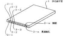
特願平7−65311号及び特願平7−233151号に係る蛇行細径トンネルプレートヒートパイプは特願平5−241916号に比較して、長さ及び大きさに制限がない、製造コストが安い等の点から実用上の効果が高いものとなる。この扁平管プレートヒートパイプは柔軟性軽金属を押出し成型してなる多孔扁平管を素材として形成される。図1にこの素材となる多孔扁平管1を斜視図にて示す。3−nは多孔を形成する貫通細孔、2−nは各貫通細孔3−nの隔壁である。図2は蛇行細径トンネルプレートヒートパイプの一部を断面で表した平面図である。図において多孔扁平管1の貫通細孔3−nの隔壁2−nはその端末においてひとつおきに切除されて隔壁切除部4−n、5−nとして封入作動液移動のターン部になっている。多孔扁平管1の両端末は隔壁切除部4−n、5−nの一部を残して圧潰部6−1、6−2において圧潰され他のち溶接封止部7−1、7−2として封止されてある。このようにして貫通細孔群3−nは一条の蛇行細径トンネルとして形成され、所定量の二相凝縮性作動液を封入の後溶接封止部8−1において溶接封止され蛇行細径トンネル内蔵のプレートヒートパイプとなる。このように形成された蛇行細径トンネル内蔵の扁平管プレートヒートパイプは如何なる形状にも自在に屈曲成型することの可能な柔軟性と可撓性を有するものであり、ステレオヒートパイプ構成用ヒートパイプとしての第一の必要条件を完全に満足する。
【0017】
またこのような蛇行細径トンネル内蔵のプレートヒートパイプは本発明者が発明し実用化した特許第1881122号(ループ型細管ヒートパイプ)、特許第1967738号(ループ型細管ヒートパイプ)、及び特開平4−251189号(マイクロヒートパイプ)の応用である蛇行細径トンネルヒートパイプを内蔵しているから、それらの発明に係るヒートパイプの優れたヒートパイプ特性を完全に備えている。即ち如何なる保持姿勢でも良好に作動する姿勢依存性の極めて少ないヒートパイプである。即ちこの細径トンネル内蔵のプレートヒートパイプはステレオヒートパイプを構成する為の第二の必要条件を完全に満足する。
【0018】
上記の通りであるから特願平7−65311号及び特願平7−233151号に係る、柔軟性軽金属を押出し成型してなる多孔扁平管を主素材として形成される蛇行細径トンネルを内蔵したプレートヒートパイプを適用することによりステレオヒートパイプを容易に構成することが出来る。
【0019】
本発明の基本的な構成について以下に説明する。ステレオ型ヒートパイプ式放熱器は立体的な熱輸送回路を有するヒートパイプであって、ヒートパイプの受熱部と放熱部の相互間を結ぶ熱輸送経路となる細管ヒートパイプコンテナが、複数の局部的受熱面から大表面積放熱部に立体的に展開される熱輸送回路を備え、または細管コンテナが立体的に展開して構成された大表面受熱部から複数の局部的放熱面に集約される熱輸送回路を備えて構成される。図3はこの様なステレオ型ヒートパイプ放熱器の構成の一例を示す斜視図であって、その基本的な構成の説明図である。図の如くこの放熱器の外周は、蛇行細径トンネルを内蔵するプレートヒートパイプ11が、その蛇行屈曲により、ステレオ型ヒートパイプ放熱器の各熱量授受面1−2、1−3、1−4、1−5に相当する複数平面を有し、且つ他の対向する対平面(開口面)が熱媒流体の流入流出面として形成されてある風洞構造の外殻体として形成されてあり、それと共にこの外殻体を形成するプレートヒートパイプ11の両内平面相互間と、必要によってはこのプレートヒートパイプ11が外殻体の内部に延長される部分11−1の両平面をも含む各平面の相互間は、相互に並列に対向する平面対向構造として形成されてあり、この平面対向構造を形成する蛇行細径トンネル内蔵のプレートヒートパイプ11を第一の構成要素とし、このプレートヒートパイプ11の対向する並列平面間を往復蛇行(螺旋蛇行を含む)して両平面間を伝熱的に接続する、長尺可撓性の蛇行ヒートパイプ11−1、11−2を第二の構成要素とし、図の如く第一及び第二の構成要素の組み合わせ体が一連の長尺プレートヒートパイプにより一体構成されてあるかして、立体的熱輸送回路が構成されてある構造を本発明の基本的な構造としている。図において13−1、13−2、13−3、13−4は発熱素子で、12−1、12−2、12−3、12−4は各発熱素子13とステレオ型ヒートパイプ放熱器の熱量授受面1−2、1−3、1−4、1−5との間の伝熱を良好ならしめる為の熱拡散プレートである。
【0020】
【作用】
(1)このようなステレオ型ヒートパイプ放熱器の特徴は、図3に示す如く六面体の中の二面を対流風15の流路として適用し、残りの四面は全て受熱面として任意に適用し、発熱素子13−1、13−2、13−3、13−4を同時または選択的に実装することが出来る。然も装着面及び装着位置による性能の差異は極めて少ない。このように本発明のステレオ型ヒートパイプ放熱器は従来のヒートパイプ放熱器に比較して発熱素子の実装自由度が飛躍的に高くなる。
【0021】
(2)蛇行細管ヒートパイプは受熱部から次の受熱部に至る距離が長い場合及びその間にターン部がある場合は作動液の管内圧力損失が増加し熱抵抗が著しく増加する。本発明のステレオ型ヒートパイプ放熱器に於て、第二構成要素の蛇行ヒートパイプは全て短い距離でターンを繰り返し、ターン部は全て受熱部となる。受熱部では作動液の管内圧力損失はキャンセルされ、新しい作動エネルギーが供給され、細管ヒートパイプの作動はターン毎に活性化され増幅される。従って第二構成要素の蛇行ヒートパイプの作動は同一長さの同一サイズのプレートヒートパイプと比較して極めて活発で高性能になる。同様な理由から発熱素子装着面に対向する面に第二の発熱素子が装着されてある場合はその部分のターン部が加熱され、ターン部の活性化作用及び増幅作用は更に強化される。この様であるから通常のヒートパイプ放熱器とは異なり、本発明のステレオ型ヒートパイプ放熱器は発熱素子装着数が多くなる程性能が向上すると云う従来のヒートパイプ放熱器には見られない優れた特長がある。
【0022】
(3)図3における矢印15の如く冷却用対流風は全て第一の構成要素の蛇行細径トンネル内蔵のプレートヒートパイプ11で形成される風洞構造内(外殻内)を流れる。この風洞構造部はヒートパイプであるから風洞としての性能と同時に放熱フィンとしての役目をも兼ねて発揮する。また本発明のステレオ型ヒートパイプ放熱器は放熱器に複数配設された各発熱素子13−1、13−2、13−3、13−4の共通放熱部即ち共通風洞として、図3に於て破線で示した風洞14の一部として適用することが出来る。従って筐体内における冷却対流風流路の配設容積を最小にとどめスペースを有効に活用することが出来る大きな利点がある。
【0023】
(4)本発明のステレオ型ヒートパイプ放熱器には複数の発熱素子が自由度高く実装することが出来るが、この放熱器自身もその実装自由度が極めて高い。従来型のヒートパイプは保持姿勢により大幅に性能が変化し、特にトップヒート姿勢の場合は使用不能状態に至るまで性能が低下するので、筐体内の装着姿勢が限定され、従って冷却風洞の取付け位置、取付け方向も限定されるものであった。それに対し本発明のステレオ型ヒートパイプ放熱器は如何なる装着姿勢でも性能が全く変化しない。従ってこの放熱器と連結一体化されてある冷却風洞14の筐体内における装着姿勢も自由度が高く、水平、垂直、傾斜、何れの方向に装着しても良い。更にその装着方向のまま、風洞の軸を中心に如何なる角度に回転せしめて取りつけても良い。この様に取付け姿勢の自由度が高いから更に取り付け位置の自由度も高いことになり、隣接実装部品の位置形状に合わせて風洞配置を決定出来ることを意味し、本発明ステレオヒートパイプ式放熱器の実装上有利な点となる。
【0024】
(5)上述の如く冷却風洞14の取り付け姿勢が自由であるから冷却風洞14を図4、に例示の如く垂直に保持することが出来ることは本発明ステレオ型ヒートパイプ放熱器1−6、1−7の大きな特長である。その効果は以下の通りである。(a)隣接する筐体内の実装部品との干渉が殆ど無くなるから装着位置及び実装設計の自由度が高くなり高密度実装を容易ならしめる。(b)複数のステレオ型ヒートパイプ放熱器を同一の垂直風洞に1−6、1−7の如く直列配置出来るから実装の立体化を容易にする。(c)垂直風洞14は他の実装部品とスペース的に干渉することが少なく、また風洞14が小型化されるから、風洞経路の周囲に十分な余裕スペースが生じる。図示は省略してあるが、このスペースを利用して消音装置を配設することが出来る。これにより騒音の発生無く強力なファンを使用して高性能化することが出来る。(d)垂直風洞14は強力な煙突効果を発生するから、図5に例示の如く自然対流冷却を効果的に実施することが出来る。従来は風洞を垂直配設することが不可能であったから密閉筐体内における自然対流冷却は極めて困難とされてきた。図において矢印15−1は強制対流風、矢印15−2は自然対流風を示している。
【0025】
(6)本発明のステレオヒートパイプ式放熱器の性能には姿勢依存性が無いから、筐体壁内外の如何なる部分に、如何なる姿勢で装着しても性能には変わりが無い。従って筐体外壁面の何れの面にもに自由に且つ有効に装着することが可能であり、これはその装着部に対応する筐体内壁面に、発熱素子を直接実装し、熱抵抗最小にて筐体外に熱量を排出することを可能にする。また同時に、筐体内スペースを最大に利用して、高密度高性能実装を可能にするものである。図6にこの様な実装状態を示す。図において1はステレオ型ヒートパイプ放熱器、13は発熱素子、14は風洞、17は冷却ファン、18−1は筐体側壁面、18−2は筐体天井壁面、18−3は筐体底壁面である。この様な筐体内スペースの有効利用は従来型ヒートパイプ応用の放熱器では全く不可能であった。
【0026】
(7)本発明のステレオ型ヒートパイプ放熱器における第二の構成要素の細管ヒートパイプ11−1、11−2は放熱フィン群の役目をする。然しこれはプレートヒートパイプであるから蛇行ピッチは通常の非ヒートパイプ放熱器のフィン群のフィンピッチの如く小ピッチに形成することは不可能である。然しこのフィン群はヒートパイプであるからフィン効率が100%であり、その全表面積が高温熱交換部として作用するから、それが極めて疎なピッチであっても通常の非ヒートパイプ放熱器よりはるかに高い放熱能力を発揮する。更にフィンピッチが極めて大きいから、冷却対流の圧力損失が通常フィン群の数分の一と極めて小さく、冷却ファンの対流発生能力に大きな余裕が発生する。従ってその余裕能力に依って流量流速を自在に制御し、放熱器の放熱能力を制御することが出来る。また蛇行ピッチが大きいから、その蛇行のピッチ間に更に精細フィン群を装着して、更に強力な強制対流冷却専用のステレオ型ヒートパイプ放熱器を構成することも出来る。この様に多彩な適用形態を有することは本発明ステレオヒートパイプ式放熱器の大きな効果である。
【0027】
【実施例】
[第一実施例] 図3は本発明のステレオヒートパイプ式放熱器の基本的構成を示す図面であると同時に本発明の第一実施例の説明図をも兼ねている。図において第一の構成要素であり、ステレオヒートパイプの風洞構造の外殻体として形成される蛇行細径トンネル内蔵のプレートヒートパイプ11と、第二の構成要素であり、第一の構成要素で形成される並列平面間を蛇行して伝熱的に接続する細管ヒートパイプ11−2、11−3とは、何れも多孔扁平管により形成された蛇行細径トンネルを内蔵したプレートヒートパイプが適用されている。多孔扁平管が適用されたプレートヒートパイプ11、11−2、11−3は他の種類のプレートヒートパイプに比較して卓越した柔軟性と可撓性を備えているから図示の如く二次成形し、自由自在に曲げ成形して適用することが出来る。またこのプレートヒートパイプ11、11−2、11−3はこのような二次成形加工によってもその性能を悪化せしめられることのない機能を有する。これ等の構成要素により構成された放熱器は図の如く六面体の立体構造に形成されてある。その中の対向する二面は矢印で示されてある対流風15の流入流出路であり、他の四面は複数同時または選択的に何れの面も受熱面1−1、1−2、1−3、1−4として適用出来るよう構成されてある。このように構成されてある本実施例の放熱器は基本構造に説明したようなステレオ型ヒートパイプ放熱器の全ての特長を備えている。図7は本実施例の構成を簡略化して表した断面略図であり、第一及び第二の構成要素をより簡略化して表すため総てを線図で示してある。本実施例は特に大容量強力なステレオ型ヒートパイプ放熱器の例を示しており、その為第一の構成要素である蛇行細径トンネル内蔵のプレートヒートパイプ11の一部11−1は風洞構造の外殻体の内部に延長せしめられ、その両平面は外殻体の内表面と共に表面積が拡大された平面対向構造部を構成している。また第一の構成要素である蛇行細径トンネル内蔵プレートヒートパイプ11、11−1は特に容量の大きいものが適用されてあることを示す為特に太線で表示されてある。
【0028】
[第二実施例] 図8は本発明のステレオ型ヒートパイプ放熱器の第二実施例の構成を示す断面略図である。第一実施例では第一構成要素と第二構成要素とは夫々独立したプレートヒートパイプ11、11−1及び11−2、11−3で形成されてあり、それらが伝熱的に接続されてステレオヒートパイプとして構成されるものであるのに対して、本第二実施例では第一構成要素と第二構成要素とは多孔扁平管で形成された蛇行細径トンネルを内蔵する一条の長尺プレートートパイプ11により連続一体化されて構成されてあることを特徴としている。この様な構成は製造工程の短縮に依るコスト低減の効果がある。また二種類のプレートヒートパイプを伝熱的に接続構成することに依り発生する熱量損失を低下せしめて熱輸送性能を向上せしめる効果がある。更にまた軽量化小型化の効果も大きい。然し本実施例においては第一構成要素と第二構成要素は全く同一の多孔扁平管コンテナにより連続一体化して形成される必要があるから、第二構成要素部となる部分が冷却フィンとしての効果を失わない程度の小ピッチ蛇行を与えることが出来るよう多孔扁平管コンテナの全体を薄形の多孔扁平管を適用して構成する必要がある。従って本実施例では厚形大容量のプレートヒートパイプを適用することが出来ないから、ある程度以上に大容量化せしめることは困難である。
【0029】
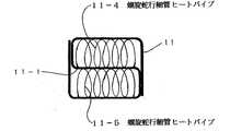
[第三実施例] 図9は本発明の第三実施例及び第四実施例の説明図であり線図から成る断面略図で示してある。本実施例においては第二の構成要素の蛇行ヒートパイプは蛇行(螺旋蛇行を含む)細管ヒートパイプ11−4、11−5であり、この蛇行ヒートパイプが第一の構成要素の平面対向部の両平面間を往復蛇行せしめられ、両平面間を伝熱的に接続して構成されてある。この伝熱的接続はろう接、溶接、挿接、圧入等に依って為される。本実施例図は螺旋蛇行細管ヒートパイプが適用されてある例を示してあり、その特徴は他の例に比較して蛇行部の形成が簡易且つ容易でありしたがって低コストに成る点がメリットである。またこの構成は螺旋ピッチを精細化することによりプレートヒートパイプを適用した第一実施例及び第二実施例より伝熱面積を拡大せしめて放熱性能を向上させることが出来る。然しその反面冷却対流風の圧力損失が若干増加する欠点もある。
【0030】
[第四実施例] 本発明のステレオ型ヒートパイプが適用される雰囲気が悪く、粉塵や油分ミスト等の付着により第二の構成要素の蛇行ヒートパイプの表面の汚染が著しく、比較的短期間毎に清掃の必要ある場合がある。図9の説明図に例示の本発明の第四実施例はその対策として案出されたものであり、本実施例のステレオ型ヒートパイプの断面略図を線図により例示してある。その基本構成は主要放熱面積となる第二の構成要素の蛇行ヒートパイプとしては、弾性金属の細管を素材としてバネ性を与えて形成された蛇行(螺旋蛇行を含む)弾性細管ヒートパイプが適用されてあり、この蛇行ヒートパイプが第一の構成要素の蛇行細径トンネル内蔵のプレートヒートパイプが並列対向する平面間に着脱自在に且つ弾性的に圧入挿接されて構成される。図9においてはその一例として蛇行ヒートパイプは螺旋蛇行弾性細管ヒートパイプ11−4、11−5が適用されてある。この蛇行ヒートパイプは清掃時には簡単な治具の助けにより極めて容易に着脱することが可能であり、ステレオ型ヒートパイプの放熱性能を常に良好に維持することが出来る点に特徴がある。
【0031】
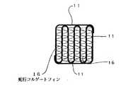
[第五実施例] 図10は本発明の第五実施例の説明図であり、本実施例のステレオ型ヒートパイプの断面略図を線図により例示してある。図において第二の構成要素の蛇行ヒートパイプ11は蛇行細径トンネル内蔵のプレートヒートパイプであり、このプレートヒートパイプ11の蛇行に依り二次的に形成される並列平面対向部の間隙に、所定の種類の精細フィン群が、ろう接、溶接、圧入、弾性的圧入等の手段に依り配設されてあることを特徴としている。図10においてはこの、精細フィン群としては蛇行コルゲートフィン16が装着されてある。精細フィン群は蛇行細線フィンであっても良く、または非ループ型蛇行細管ヒートパイプフィンであっても良く、それらのフィンの蛇行は通常の蛇行でも、螺旋蛇行であっても良い。それらのフィン群はプレートヒートパイプ11の蛇行に依り二次的に形成される並列平面対向部の間隙に装着することが可能な精細フィン群であれば如何なるフィン群であっても良い。またその装着方法はろう接、溶接、何れの手段であっても良い。更に精細フィン群は上記各種フィン群が弾性金属で形成されたスプリングフィン群が着脱自在に挿接圧入されたものであっても良い。本発明にかかるステレオ型ヒートパイプはそれ自身極めて放熱性能の良い放熱器ではあるが、その並列平面対向部の間隙に蛇行して装着される第二構成要素の蛇行ピッチは十分に大きいので、第二構成要素がプレートヒートパイプであればそれにさらに二次的に並列平面対向部が形成されるから、この間隙に精細フィンを装着してステレオ型ヒートパイプの放熱能力を更に倍増せしめることが出来る。然しこの様な本実施例の高性能放熱器は余りにフィン間隙が狭くなり、対流風の圧力損失が増加するので自然空冷用放熱器としては不適当となる。
【0032】
【発明の効果】
蛇行細径トンネルヒートパイプを内蔵した、柔軟性及び可撓性に富むプレートヒートパイプを素材として適用することにより、それを多面体に屈曲成形し、風洞状外殻体を有し、その内部に放熱部が配設されてあり、この放熱部に充分な風量の冷却対流風を低圧力損失で送入排出せしめることの可能な構造の高性能ステレオ型ヒートパイプ放熱器の製作に成功した。その構造上で寄与する点はプレートヒートパイプの柔軟可撓性にあった。性能上で寄与する点はプレートヒートパイプの薄形化と内蔵する蛇行細径トンネルヒートパイプに姿勢依存性が無いことにあった。完成したステレオ型ヒートパイプに姿勢依存性が全く無い点は筐体内部における発熱素子、部品の実装自由度の拡大と実装の高密度化に貢献し、機器の小型化軽量化に貢献する。また風洞の垂直装着を可能にすることにより密閉筐体内における自然空冷を可能にする点は実装技術の革新に貢献するものと信ぜられる。
【図面の簡単な説明】
【図1】本発明の構成素材となる多孔扁平金属管の構造を示す斜視図である。
【図2】本発明の主要構成要素となる蛇行細径トンネルヒートパイプを内蔵するプレートヒートパイプの構造を示す一部断面の平面図である。
【図3】本発明のステレオ型ヒートパイプ放熱器の基本的構造を示す斜視図であり、且つ本発明の第一実施例を示す斜視図である。
【図4】本発明のステレオ型ヒートパイプ放熱器の適用例を示す説明図である。
【図5】本発明のステレオ型ヒートパイプ放熱器の他の適用例を示す説明図である。
【図6】本発明のステレオ型ヒートパイプ放熱器の更にその他の適用例を示す説明図である。
【図7】本発明のステレオ型ヒートパイプ放熱器の第一実施例の構造を線画略図で示す断面説明図である。
【図8】本発明のステレオ型ヒートパイプ放熱器の第二実施例の構造を線画略図で示す断面説明図である。
【図9】本発明のステレオ型ヒートパイプ放熱器の第三実施例および第四実施例共通の図面であり、それらの構造を線画略図で示す断面説明図である。
【図10】本発明のステレオ型ヒートパイプ放熱器の第五実施例の構造を線画略図で示す断面説明図である。
【図11】従来型のヒートパイプによる三次元熱交換の一例を示す斜視図である。
【図12】従来型のヒートパイプによる三次元熱交換の他の一例を示す斜視図である。
【図13】従来型のステレオ型ヒートパイプ放熱器の構造例を示す側面図である。
【符号の説明】
1 多孔扁平管
1−1 熱量授受面
1−6 ステレオ型ヒートパイプ放熱器
2 隔壁
3 貫通細孔
4 隔壁切除部
5 隔壁切除部
6 圧潰部
7 溶接封止部
8 作動液注入孔
8−1 溶接封止部
11 第一構成要素プレートヒートパイプ
11−1 延長部
11−2 第二構成要素細管ヒートパイプ
11−4 螺旋蛇行細管ヒートパイプ
12 熱拡散プレート
13 発熱素子
14 風洞
15 対流風
15−1 強制対流風
15−2 自然対流風
16 蛇行コルゲートフィン
17 冷却ファン
18 筐体壁
18−1 筐体側壁面
18−2 筐体天井壁面
18−3 筐体底壁面[0001]
[Industrial application fields]
The present invention relates to a heat pipe applied heat radiator, and more particularly to a stereo heat pipe heat radiator in which a long heat pipe container is meandered and bent to form a three-dimensional heat transport circuit.
[0002]
[Prior art]
Although conventional heat pipes are good heat transport means, their heat transport path is generally one-dimensional heat transport in the linear direction along the axis of the pipe. To replace this with two-dimensional surface heat transport, flat fins It was necessary to carry out by the combination. In addition, examples of application of the conventional heat pipe in the case where three-dimensional heat exchange is required as in the case of heat exchange with a fluid or heat exchange between fluids are as shown in FIGS. 11, 12 and 13 (a ), (B), and (c).
[0003]
FIG. 11, Example (a) is an example in which a three-dimensional heat exchange is performed by three-dimensionally configuring a heat radiating portion by a plate-like fin group 33-n inserted orthogonally to a
[0004]
In FIG. 12, example (b), another example is a case where a conventional thin tube heat pipe group 31-n is three-dimensionally arranged in parallel and parallel to form a so-called multi-tubular heat exchanger to perform three-dimensional heat exchange. there were. In the figure, 32-2 is a heating element, 32-3 is a heat receiving block, and 34 is a convection air.
[0005]
FIG. 13, Example (c), and as another example, after drilling the small-diameter tunnel group 36-n cross-connected in a three-dimensional lattice in a hexahedral metal heat receiving block 32-3, each tunnel opening is formed. A semiconductor element cooling stereo that is hermetically sealed with a sealing cap group 38-n to form a three-dimensional thin tunnel heat pipe container, and a through hole group is formed in a lattice gap to form a cooling air flow path group 37-n. An example of an experimental heat pipe radiator has been announced. In the figure, reference numeral 32-2 denotes a heating element.
[0006]
[Problems to be solved by the invention]
In each application example above
In the case of the example (a), since the plate-like fin diffuses the amount of heat by heat conduction between metals, the fin temperature rapidly decreases as the distance between the heat pipe and the bonding portion of the fin increases, and therefore the fin area As the fin efficiency increases, the fin efficiency decreases, the heat exchange efficiency also decreases, and the fins become larger in series as the exchange heat amount increases. Therefore, this tendency is further increased when the plate-like fin group 33-n is used for three-dimensional heat exchange, and the increase in volume and weight of the heat exchange part have been problems.
[0007]
In the case of example (b), there is not much problem when three-dimensional heat exchange of fluid is performed for both receiving and radiating heat. However, when the amount of heat received at the local area is radiated by three-dimensional heat exchange, the local heat reception is not as it is. It is possible to attach a large heat receiving block 32-3 to the heat receiving portion, and to receive heat through this, and the overall size of the device increases and the weight increases in proportion to the amount of heat to be transported. It was a problem.
[0008]
In the case of example (c), according to the published data of the experimental results, the surrounding area of the small diameter tunnel heat is caused by the fact that the inner area of the cooling air flow path group 37-n is too small and the heat exchange area is extremely insufficient. Although the heat exchange capacity per unit area is extremely large due to the action of the pipe group 36-n, the heat resistance performance of the radiator expected by the industry for this type of radiator is less than 0.25 ° C / W. The heat resistance value of the heatsink was extremely bad at 2.0 ° C./W, and the possibility of practical use was considered to be extremely small. The structure of this experimental example was estimated to require a great deal of time for production, and it was judged that practical use was almost impossible from the viewpoint of high cost.
[0009]
However, in the experimental example of the example (c), such a three-dimensional structure heat pipe is extremely high if the heat exchange area of the cooling air flow path group 37-n can be brought close to the heat exchange area of a normal radiator. It suggested that it would perform well. Further, it has been suggested that if a large number of sealing portion protrusions can be eliminated, it is possible to mount a plurality of heating elements, which is another effect as a three-dimensional structure heat pipe. However, it has been speculated that it is difficult to mount such a plurality of heat generating elements because the posture dependence is usually large in application of a heat pipe.
[0010]
In the prior art, the three-dimensional heat exchange using the conventional heat pipe has the above-mentioned problems, but has been accepted as practically unsolved. However, remarkable advances in recent semiconductor technologies have led to the miniaturization of semiconductor elements themselves and the increase in heat generation, and further promoted the three-dimensional mounting and high-density mounting of components in semiconductor device application equipment, and the significant miniaturization of equipment. The conventional three-dimensional heat exchange structure using heat pipes is becoming impossible to cope with. Currently, there is a strong demand in the industry to increase the degree of freedom in mounting the heating elements and increase the heat receiving and radiating capacity of the stereo heat pipe radiator such as the three-dimensional structure heat pipe of the above-described experimental example.
[0011]
[Means for solving the problems]
It is most appropriate in the production of a three-dimensional structure heat pipe (hereinafter referred to as a stereo heat pipe) to use a plate heat pipe with a meandering small diameter tunnel instead of the tunnel heat pipe from the experimental example of (c) in the prior art. It was considered that. This is to minimize the cross-sectional area of the heat pipe when the cross-sectional area of the radiator perpendicular to the cooling convection flow direction is constant in a stereo heat pipe that requires a small volume and a small weight. And allows the cross-sectional area of the cooling convection channel to be maximized. This means that the heat dissipating performance of the heat radiator using the stereo heat pipe is improved to the maximum.
[0012]
The first requirement for a heat pipe to construct a stereo heat pipe is that it is a flexible and flexible thin heat pipe that can be bent and applied to the required shape and configured in three dimensions. Such a thin heat pipe facilitates the construction of the stereo heat pipe and reduces the resistance cross-sectional area with respect to the convection flow direction. This also makes it possible to construct a stereo heat pipe of the right weight and the right price.
[0013]
The second requirement of the heat pipe for constructing a stereo heat pipe is that it is a heat pipe having a low attitude dependency that works well in any holding attitude. The stereo heat pipe is bottom heat in some parts, horizontal heat in other parts, and top heat in other parts, so it works well in any part, that is, it needs less posture dependency. The
In the conventional heat pipe, it is impossible to satisfy both the first and second conditions.
[0014]
The meandering small-diameter tunnel plate heat pipes invented and put into practical use by the present inventors (Japanese Patent Application Nos. 5-241916, 7-65311 and 7-233151) are used to construct a stereo heat pipe. The first and second conditions are fully satisfied, and the construction of various stereo heat pipes requested by the industry is facilitated.
[0015]
In the plate-type heat pipe according to Japanese Patent Application No. 5-241916, a meandering narrow groove pattern is formed on the surface of a thin plate, and this plate is laminated and bonded to form a plate having a meandering narrow tunnel. Is configured as a heat pipe container, and its function with excellent bending workability and extremely low posture dependency completely satisfies the first and second conditions. Therefore, the diameter plate type heat pipe according to Japanese Patent Application No. 5-241916 is a plate heat pipe suitable for constituting the stereo human pipe type radiator of the present invention.
However, it is difficult to increase the size of this plate-type heat pipe due to its construction, and there is a problem that the manufacturing cost is relatively expensive except in the case of mass production. It was limited to the field of vessels.
[0016]
The meandering small diameter tunnel plate heat pipe according to Japanese Patent Application No. 7-65311 and Japanese Patent Application No. 7-233151 is not limited in length and size as compared with Japanese Patent Application No. 5-241916. The practical effect is high from the point of being cheap. This flat tube plate heat pipe is formed from a porous flat tube formed by extruding a flexible light metal. FIG. 1 is a perspective view showing a porous
[0017]
Such plate heat pipes having a meandering small diameter tunnel are disclosed in Japanese Patent No. 1881122 (loop-type thin tube heat pipe), Japanese Patent No. 19677738 (loop-type thin tube heat pipe), invented and put into practical use by the present inventors. Since the meandering small diameter tunnel heat pipe, which is an application of No. 4-25189 (micro heat pipe), is built in, the excellent heat pipe characteristics of the heat pipes according to those inventions are completely provided. In other words, it is a heat pipe with very little posture dependency that works well in any holding posture. In other words, this plate heat pipe with a small diameter tunnel completely satisfies the second requirement for constructing a stereo heat pipe.
[0018]
Since it is as described above, it has a meandering small-diameter tunnel formed mainly by a porous flat tube formed by extruding a flexible light metal according to Japanese Patent Application Nos. 7-65311 and 7-233151. A stereo heat pipe can be easily configured by applying a plate heat pipe.
[0019]
The basic configuration of the present invention will be described below. A stereo heat pipe radiator is a heat pipe having a three-dimensional heat transport circuit, and a thin tube heat pipe container serving as a heat transport path connecting the heat receiving part and the heat radiating part of the heat pipe is divided into a plurality of local heat pipes. Heat transport that has a heat transport circuit that is three-dimensionally developed from the heat receiving surface to the large surface area heat dissipating unit, or that is concentrated on a plurality of local heat dissipating surfaces from a large surface heat receiving unit configured by three-dimensionally deploying a thin tube container It is configured with a circuit. FIG. 3 is a perspective view showing an example of the configuration of such a stereo heat pipe radiator, and is an explanatory view of the basic configuration. As shown in the figure, on the outer periphery of this radiator, a
[0020]
[Action]
(1) The feature of such a stereo heat pipe radiator is that two faces in the hexahedron are applied as a flow path of the convection air 15 as shown in FIG. 3, and the remaining four faces are arbitrarily applied as heat receiving faces. The heating elements 13-1, 13-2, 13-3, 13-4 can be mounted simultaneously or selectively. However, there is very little difference in performance depending on the mounting surface and mounting position. As described above, the stereo heat pipe radiator of the present invention greatly increases the degree of freedom of mounting the heat generating element as compared with the conventional heat pipe radiator.
[0021]
(2) When the distance from the heat receiving portion to the next heat receiving portion is long and when there is a turn portion between the heat receiving portion and the meandering tube heat pipe, the pressure loss of the hydraulic fluid in the tube increases and the thermal resistance increases remarkably. In the stereo heat pipe radiator of the present invention, all the meandering heat pipes of the second component repeat a turn at a short distance, and all the turn parts become heat receiving parts. In the heat receiving section, the pressure loss of the hydraulic fluid in the pipe is canceled, new operating energy is supplied, and the operation of the narrow pipe heat pipe is activated and amplified every turn. Thus, the operation of the second component serpentine heat pipe is very active and high performance compared to the same length plate heat pipe of the same size. For the same reason, when the second heat generating element is mounted on the surface facing the heat generating element mounting surface, the turn portion of the portion is heated, and the activation and amplification functions of the turn portion are further strengthened. Because of this, unlike a normal heat pipe radiator, the stereo heat pipe radiator of the present invention is superior to the conventional heat pipe radiator that the performance improves as the number of heating elements increases. There are special features.
[0022]
(3) As shown by the arrow 15 in FIG. 3, all the convection air for cooling flows in the wind tunnel structure (inside the outer shell) formed by the
[0023]
(4) Although a plurality of heat generating elements can be mounted with a high degree of freedom in the stereo heat pipe radiator of the present invention, this heat radiator itself has a very high degree of freedom in mounting. The performance of conventional heat pipes varies greatly depending on the holding posture, and in the case of the top heat posture, the performance deteriorates until it becomes unusable, so the mounting posture in the housing is limited, and therefore the mounting position of the cooling wind tunnel The mounting direction was also limited. In contrast, the performance of the stereo heat pipe radiator of the present invention does not change at all in any mounting posture. Therefore, the mounting orientation of the
[0024]
(5) Since the mounting posture of the
[0025]
(6) Since the performance of the stereo heat pipe type radiator of the present invention has no posture dependency, the performance does not change even if it is mounted in any position inside or outside the housing wall. Therefore, it can be freely and effectively mounted on any surface of the outer wall surface of the housing. This is because the heating element is directly mounted on the inner wall surface of the housing corresponding to the mounting portion, and the housing has the minimum thermal resistance. It makes it possible to discharge heat outside the body. At the same time, high-density and high-performance mounting is enabled by making maximum use of the space in the housing. FIG. 6 shows such a mounting state. In the figure, 1 is a stereo heat pipe radiator, 13 is a heating element, 14 is a wind tunnel, 17 is a cooling fan, 18-1 is a side wall of the casing, 18-2 is a ceiling wall of the casing, and 18-3 is a bottom wall of the casing. It is. Such effective use of the space in the housing has never been possible with a conventional heat pipe radiator.
[0026]
(7) The thin tube heat pipes 11-1 and 11-2 as the second component in the stereo heat pipe radiator of the present invention serve as a radiating fin group. However, since this is a plate heat pipe, it is impossible to form the meandering pitch as small as the fin pitch of the fin group of a normal non-heat pipe radiator. However, since this fin group is a heat pipe, the fin efficiency is 100%, and its entire surface area acts as a high-temperature heat exchange part, so even if it is an extremely sparse pitch, it is much more than a normal non-heat pipe radiator High heat dissipation capability. Furthermore, since the fin pitch is extremely large, the pressure loss of cooling convection is usually as small as a fraction of that of the fin group, and a large margin is generated in the convection generating capacity of the cooling fan. Therefore, the flow rate and flow rate can be freely controlled according to the margin capacity, and the heat dissipation capability of the radiator can be controlled. Further, since the meandering pitch is large, it is possible to construct a more powerful stereo heat pipe radiator dedicated to forced convection cooling by mounting fine fin groups between the meandering pitches. Having such various application forms is a great effect of the stereo heat pipe radiator of the present invention.
[0027]
【Example】
First Embodiment FIG. 3 is a drawing showing the basic configuration of a stereo heat pipe radiator of the present invention, and at the same time serves as an explanatory diagram of the first embodiment of the present invention. In the figure, a
[0028]
Second Embodiment FIG. 8 is a schematic cross-sectional view showing the configuration of a second embodiment of the stereo heat pipe radiator of the present invention. In the first embodiment, the first component and the second component are formed by independent
[0029]
[Third Embodiment] FIG. 9 is an explanatory diagram of a third embodiment and a fourth embodiment of the present invention, and is shown by a schematic cross-sectional view composed of a diagram. In this embodiment, the meandering heat pipes of the second component are meandering (including spiral meandering) thin tube heat pipes 11-4 and 11-5. The two planes are meandered back and forth, and the two planes are connected by heat transfer. This heat transfer connection is made by brazing, welding, insertion, press fitting, or the like. This embodiment shows an example in which a spiral meandering capillary heat pipe is applied, and its feature is that the formation of the meandering portion is simpler and easier than the other examples, and therefore the cost is low. is there. In addition, this configuration can improve the heat radiation performance by enlarging the heat transfer area as compared with the first and second embodiments in which the plate heat pipe is applied by refining the helical pitch. However, there is a drawback that the pressure loss of the cooling convection air slightly increases.
[0030]
[Fourth embodiment] The atmosphere to which the stereo heat pipe of the present invention is applied is poor, and the surface of the meandering heat pipe of the second component is significantly contaminated due to adhesion of dust, oil mist, etc. May need cleaning. The fourth embodiment of the present invention illustrated in the explanatory diagram of FIG. 9 is devised as a countermeasure, and a schematic cross-sectional view of the stereo heat pipe of the present embodiment is illustrated by a diagram. As a meandering heat pipe of the second component, whose basic structure is the main heat dissipation area, meandering (including spiral meandering) elastic thin tube heat pipes, which are made of elastic metal thin tubes as a raw material, are applied. The meandering heat pipe is configured such that a plate heat pipe having a meandering narrow tunnel, which is the first component, is detachably and elastically press-fitted and inserted between planes facing each other in parallel. In FIG. 9, as an example, spiral meandering elastic thin tube heat pipes 11-4 and 11-5 are applied as meandering heat pipes. This meandering heat pipe can be attached and detached very easily with the help of a simple jig during cleaning, and is characterized in that the heat dissipation performance of the stereo heat pipe can always be kept good.
[0031]
[Fifth Embodiment] FIG. 10 is an explanatory diagram of a fifth embodiment of the present invention, and a schematic cross-sectional view of a stereo heat pipe of the present embodiment is illustrated by a diagram. In the figure, the meandering
[0032]
【The invention's effect】
By applying a flexible and flexible plate heat pipe with a meandering small-diameter tunnel heat pipe as a material, it is bent into a polyhedron and has a wind tunnel-like outer shell with heat dissipation inside. A high-performance stereo heat pipe radiator with a structure that can send and discharge cooling convection air with a sufficient air flow with low pressure loss to the heat radiating part has been successfully produced. The point contributing to the structure was the soft flexibility of the plate heat pipe. The contribution to performance was that the plate heat pipe was made thinner and the built-in meandering small diameter tunnel heat pipe had no attitude dependency. The fact that the completed stereo heat pipe has no attitude dependency contributes to the expansion of the mounting flexibility of the heat generating elements and components inside the housing and the high density of the mounting, and contributes to the miniaturization and weight reduction of the equipment. In addition, it is believed that natural air cooling in a sealed enclosure by enabling vertical mounting of wind tunnels will contribute to innovation in packaging technology.
[Brief description of the drawings]
FIG. 1 is a perspective view showing a structure of a porous flat metal tube as a constituent material of the present invention.
FIG. 2 is a partial cross-sectional plan view showing the structure of a plate heat pipe having a meandering small-diameter tunnel heat pipe as a main component of the present invention.
FIG. 3 is a perspective view showing a basic structure of a stereo heat pipe radiator of the present invention and a perspective view showing a first embodiment of the present invention.
FIG. 4 is an explanatory view showing an application example of a stereo heat pipe radiator of the present invention.
FIG. 5 is an explanatory view showing another application example of the stereo heat pipe radiator of the present invention.
FIG. 6 is an explanatory view showing still another application example of the stereo heat pipe radiator of the present invention.
FIG. 7 is a cross-sectional explanatory view showing the structure of the first embodiment of the stereo heat pipe radiator of the present invention in a schematic line drawing.
FIG. 8 is a cross-sectional explanatory view schematically showing the structure of a second embodiment of the stereo heat pipe radiator of the present invention in a line drawing.
FIG. 9 is a drawing common to the third embodiment and the fourth embodiment of the stereo heat pipe radiator of the present invention, and is a cross-sectional explanatory view showing the structure thereof in a line drawing schematic diagram.
FIG. 10 is an explanatory cross-sectional view schematically showing the structure of a fifth embodiment of the stereo heat pipe radiator of the present invention in a line drawing.
FIG. 11 is a perspective view showing an example of three-dimensional heat exchange by a conventional heat pipe.
FIG. 12 is a perspective view showing another example of three-dimensional heat exchange using a conventional heat pipe.
FIG. 13 is a side view showing a structural example of a conventional stereo heat pipe radiator.
[Explanation of symbols]
1 porous flat tube
1-1 Heat transfer surface
1-6 Stereo heat pipe radiator
2 Bulkhead
3 Through pores
4 Bulkhead resection
5 Bulkhead resection
6 Crushing part
7 Weld seal
8 Hydraulic fluid injection hole
8-1 Weld seal
11 First component plate heat pipe
11-1 Extension
11-2 Second component capillary heat pipe
11-4 Spiral meandering tubule heat pipe
12 Thermal diffusion plate
13 Heating element
14 Wind tunnel
15 Convection wind
15-1 Forced convection
15-2 Natural convection wind
16 Meander corrugated fin
17 Cooling fan
18 Housing wall
18-1 Housing side wall
18-2 Housing ceiling wall
18-3 Case bottom wall
Claims (6)
Translated fromJapanesePriority Applications (1)
| Application Number | Priority Date | Filing Date | Title |
|---|---|---|---|
| JP14966296AJP3959428B2 (en) | 1996-05-09 | 1996-05-09 | Stereo heat pipe radiator |
Applications Claiming Priority (1)
| Application Number | Priority Date | Filing Date | Title |
|---|---|---|---|
| JP14966296AJP3959428B2 (en) | 1996-05-09 | 1996-05-09 | Stereo heat pipe radiator |
Publications (2)
| Publication Number | Publication Date |
|---|---|
| JPH09303983A JPH09303983A (en) | 1997-11-28 |
| JP3959428B2true JP3959428B2 (en) | 2007-08-15 |
Family
ID=15480115
Family Applications (1)
| Application Number | Title | Priority Date | Filing Date |
|---|---|---|---|
| JP14966296AExpired - LifetimeJP3959428B2 (en) | 1996-05-09 | 1996-05-09 | Stereo heat pipe radiator |
Country Status (1)
| Country | Link |
|---|---|
| JP (1) | JP3959428B2 (en) |
Families Citing this family (5)
| Publication number | Priority date | Publication date | Assignee | Title |
|---|---|---|---|---|
| JP4659989B2 (en)* | 2001-02-15 | 2011-03-30 | 帝人ファーマ株式会社 | Medical oxygen concentrator |
| JP4880822B2 (en)* | 2001-04-03 | 2012-02-22 | ティーエス ヒートロニクス 株式会社 | Heat dissipation device |
| JP2014009935A (en)* | 2012-07-02 | 2014-01-20 | Cbc Est Co Ltd | Quick cooling device for liquid |
| CN107300479B (en)* | 2017-08-16 | 2023-11-14 | 国网湖南省电力公司 | Test platform for SVG heat pipe radiator characteristics and application method thereof |
| CN117881077B (en)* | 2024-03-12 | 2024-05-28 | 北京钧天航宇技术有限公司 | Integrated thermal control structure and active equipment |
Family Cites Families (3)
| Publication number | Priority date | Publication date | Assignee | Title |
|---|---|---|---|---|
| JPH0341478Y2 (en)* | 1985-11-25 | 1991-08-30 | ||
| JPH06174386A (en)* | 1992-10-19 | 1994-06-24 | Akutoronikusu Kk | Thermal connection tape |
| JP2544701B2 (en)* | 1993-08-24 | 1996-10-16 | アクトロニクス株式会社 | Plate type heat pipe |
- 1996
- 1996-05-09JPJP14966296Apatent/JP3959428B2/ennot_activeExpired - Lifetime
Also Published As
| Publication number | Publication date |
|---|---|
| JPH09303983A (en) | 1997-11-28 |
Similar Documents
| Publication | Publication Date | Title |
|---|---|---|
| JP5323614B2 (en) | Heat pipe and manufacturing method thereof | |
| CN211240587U (en) | Heat radiator | |
| JP4867411B2 (en) | Cooling device for electronic equipment | |
| CN211457798U (en) | Heat radiator | |
| JP2004293833A (en) | Cooling device | |
| JP4013883B2 (en) | Heat exchanger | |
| JP3959428B2 (en) | Stereo heat pipe radiator | |
| CN113556914A (en) | Heat dissipation pipe, heat dissipation module and liquid cooling system | |
| JP3713633B2 (en) | Closed temperature control system | |
| JP7113914B2 (en) | Heatsinks, heatsink assemblies, electronics, and methods of making heatsinks | |
| JP2001251079A (en) | Heat sink using heat pipe and method of manufacturing heat pipe | |
| CN216852896U (en) | Heat abstractor and industrial control equipment | |
| JP5076476B2 (en) | Cooling system | |
| CN214014852U (en) | Die-casting or casting type liquid cooling radiator, air conditioner frequency converter thereof and electronic equipment | |
| JP4128935B2 (en) | Water-cooled heat sink | |
| JPH10185466A (en) | Heat pipe radiator | |
| JP4363501B2 (en) | Modular composite heat sink | |
| JP2010007867A (en) | Radiator tank and its manufacturing method | |
| JP2004156835A (en) | Element radiator | |
| CN113710050A (en) | Heat radiator | |
| JP4753131B2 (en) | Element heatsink | |
| KR102855031B1 (en) | High-efficiency oval-shaped finned tube heat exchanger using turbulence generation | |
| JPS60232496A (en) | Heat exchanger | |
| CN216852886U (en) | Heat radiation structure | |
| CN220340658U (en) | Novel heat pipe radiator |
Legal Events
| Date | Code | Title | Description |
|---|---|---|---|
| A625 | Written request for application examination (by other person) | Free format text:JAPANESE INTERMEDIATE CODE: A625 Effective date:20030509 | |
| A621 | Written request for application examination | Free format text:JAPANESE INTERMEDIATE CODE: A621 Effective date:20030509 | |
| A977 | Report on retrieval | Free format text:JAPANESE INTERMEDIATE CODE: A971007 Effective date:20060221 | |
| A711 | Notification of change in applicant | Free format text:JAPANESE INTERMEDIATE CODE: A711 Effective date:20060224 | |
| A131 | Notification of reasons for refusal | Free format text:JAPANESE INTERMEDIATE CODE: A131 Effective date:20060711 | |
| A521 | Written amendment | Free format text:JAPANESE INTERMEDIATE CODE: A523 Effective date:20060911 | |
| A01 | Written decision to grant a patent or to grant a registration (utility model) | Free format text:JAPANESE INTERMEDIATE CODE: A01 Effective date:20070123 | |
| A61 | First payment of annual fees (during grant procedure) | Free format text:JAPANESE INTERMEDIATE CODE: A61 Effective date:20070309 | |
| R150 | Certificate of patent or registration of utility model | Free format text:JAPANESE INTERMEDIATE CODE: R150 | |
| FPAY | Renewal fee payment (event date is renewal date of database) | Free format text:PAYMENT UNTIL: 20100525 Year of fee payment:3 | |
| S201 | Request for registration of exclusive licence | Free format text:JAPANESE INTERMEDIATE CODE: R314201 | |
| FPAY | Renewal fee payment (event date is renewal date of database) | Free format text:PAYMENT UNTIL: 20100525 Year of fee payment:3 | |
| R350 | Written notification of registration of transfer | Free format text:JAPANESE INTERMEDIATE CODE: R350 | |
| FPAY | Renewal fee payment (event date is renewal date of database) | Free format text:PAYMENT UNTIL: 20110525 Year of fee payment:4 | |
| S111 | Request for change of ownership or part of ownership | Free format text:JAPANESE INTERMEDIATE CODE: R313113 | |
| FPAY | Renewal fee payment (event date is renewal date of database) | Free format text:PAYMENT UNTIL: 20110525 Year of fee payment:4 | |
| R360 | Written notification for declining of transfer of rights | Free format text:JAPANESE INTERMEDIATE CODE: R360 | |
| FPAY | Renewal fee payment (event date is renewal date of database) | Free format text:PAYMENT UNTIL: 20110525 Year of fee payment:4 | |
| R370 | Written measure of declining of transfer procedure | Free format text:JAPANESE INTERMEDIATE CODE: R370 | |
| S111 | Request for change of ownership or part of ownership | Free format text:JAPANESE INTERMEDIATE CODE: R313113 | |
| FPAY | Renewal fee payment (event date is renewal date of database) | Free format text:PAYMENT UNTIL: 20110525 Year of fee payment:4 | |
| R350 | Written notification of registration of transfer | Free format text:JAPANESE INTERMEDIATE CODE: R350 | |
| FPAY | Renewal fee payment (event date is renewal date of database) | Free format text:PAYMENT UNTIL: 20120525 Year of fee payment:5 | |
| FPAY | Renewal fee payment (event date is renewal date of database) | Free format text:PAYMENT UNTIL: 20120525 Year of fee payment:5 | |
| S111 | Request for change of ownership or part of ownership | Free format text:JAPANESE INTERMEDIATE CODE: R313113 | |
| FPAY | Renewal fee payment (event date is renewal date of database) | Free format text:PAYMENT UNTIL: 20120525 Year of fee payment:5 | |
| R350 | Written notification of registration of transfer | Free format text:JAPANESE INTERMEDIATE CODE: R350 | |
| FPAY | Renewal fee payment (event date is renewal date of database) | Free format text:PAYMENT UNTIL: 20120525 Year of fee payment:5 | |
| FPAY | Renewal fee payment (event date is renewal date of database) | Free format text:PAYMENT UNTIL: 20130525 Year of fee payment:6 | |
| FPAY | Renewal fee payment (event date is renewal date of database) | Free format text:PAYMENT UNTIL: 20130525 Year of fee payment:6 | |
| R250 | Receipt of annual fees | Free format text:JAPANESE INTERMEDIATE CODE: R250 | |
| R250 | Receipt of annual fees | Free format text:JAPANESE INTERMEDIATE CODE: R250 | |
| EXPY | Cancellation because of completion of term |