JP3956878B2 - Piping joint structure and piping joint connection method - Google Patents
Piping joint structure and piping joint connection methodDownload PDFInfo
- Publication number
- JP3956878B2 JP3956878B2JP2003077900AJP2003077900AJP3956878B2JP 3956878 B2JP3956878 B2JP 3956878B2JP 2003077900 AJP2003077900 AJP 2003077900AJP 2003077900 AJP2003077900 AJP 2003077900AJP 3956878 B2JP3956878 B2JP 3956878B2
- Authority
- JP
- Japan
- Prior art keywords
- pipe joint
- pipe
- piping
- joint
- distal end
- Prior art date
- Legal status (The legal status is an assumption and is not a legal conclusion. Google has not performed a legal analysis and makes no representation as to the accuracy of the status listed.)
- Expired - Fee Related
Links
- 238000000034methodMethods0.000titleclaimsdescription34
- 238000003780insertionMethods0.000claimsdescription40
- 230000037431insertionEffects0.000claimsdescription40
- 238000005057refrigerationMethods0.000claimsdescription32
- 238000005452bendingMethods0.000claimsdescription9
- 238000002788crimpingMethods0.000claimsdescription8
- 239000003507refrigerantSubstances0.000description7
- 230000008878couplingEffects0.000description5
- 238000010168coupling processMethods0.000description5
- 238000005859coupling reactionMethods0.000description5
- XEEYBQQBJWHFJM-UHFFFAOYSA-NIronChemical compound[Fe]XEEYBQQBJWHFJM-UHFFFAOYSA-N0.000description4
- 238000000465mouldingMethods0.000description4
- 238000005219brazingMethods0.000description3
- 239000007769metal materialSubstances0.000description3
- -1polypropylenePolymers0.000description3
- 229910001369BrassInorganic materials0.000description2
- RYGMFSIKBFXOCR-UHFFFAOYSA-NCopperChemical compound[Cu]RYGMFSIKBFXOCR-UHFFFAOYSA-N0.000description2
- 229910052782aluminiumInorganic materials0.000description2
- XAGFODPZIPBFFR-UHFFFAOYSA-NaluminiumChemical compound[Al]XAGFODPZIPBFFR-UHFFFAOYSA-N0.000description2
- 239000010951brassSubstances0.000description2
- 229910052802copperInorganic materials0.000description2
- 239000010949copperSubstances0.000description2
- 229910052742ironInorganic materials0.000description2
- 239000011347resinSubstances0.000description2
- 229920005989resinPolymers0.000description2
- 229910001220stainless steelInorganic materials0.000description2
- 239000010935stainless steelSubstances0.000description2
- 239000004593EpoxySubstances0.000description1
- 239000004677NylonSubstances0.000description1
- 229930040373ParaformaldehydeNatural products0.000description1
- ISWSIDIOOBJBQZ-UHFFFAOYSA-NPhenolChemical compoundOC1=CC=CC=C1ISWSIDIOOBJBQZ-UHFFFAOYSA-N0.000description1
- 239000004698PolyethyleneSubstances0.000description1
- 239000004734Polyphenylene sulfideSubstances0.000description1
- 239000004743PolypropyleneSubstances0.000description1
- 238000010586diagramMethods0.000description1
- 239000000463materialSubstances0.000description1
- 229920001778nylonPolymers0.000description1
- 230000035515penetrationEffects0.000description1
- 230000002093peripheral effectEffects0.000description1
- 229920000573polyethylenePolymers0.000description1
- 229920006324polyoxymethylenePolymers0.000description1
- 229920000069polyphenylene sulfidePolymers0.000description1
- 229920001155polypropylenePolymers0.000description1
- 238000007493shaping processMethods0.000description1
- 230000007704transitionEffects0.000description1
- XLYOFNOQVPJJNP-UHFFFAOYSA-NwaterSubstancesOXLYOFNOQVPJJNP-UHFFFAOYSA-N0.000description1
Images


Classifications
- B—PERFORMING OPERATIONS; TRANSPORTING
- B21—MECHANICAL METAL-WORKING WITHOUT ESSENTIALLY REMOVING MATERIAL; PUNCHING METAL
- B21D—WORKING OR PROCESSING OF SHEET METAL OR METAL TUBES, RODS OR PROFILES WITHOUT ESSENTIALLY REMOVING MATERIAL; PUNCHING METAL
- B21D39/00—Application of procedures in order to connect objects or parts, e.g. coating with sheet metal otherwise than by plating; Tube expanders
- B21D39/06—Application of procedures in order to connect objects or parts, e.g. coating with sheet metal otherwise than by plating; Tube expanders of tubes in openings, e.g. rolling-in
- F—MECHANICAL ENGINEERING; LIGHTING; HEATING; WEAPONS; BLASTING
- F16—ENGINEERING ELEMENTS AND UNITS; GENERAL MEASURES FOR PRODUCING AND MAINTAINING EFFECTIVE FUNCTIONING OF MACHINES OR INSTALLATIONS; THERMAL INSULATION IN GENERAL
- F16L—PIPES; JOINTS OR FITTINGS FOR PIPES; SUPPORTS FOR PIPES, CABLES OR PROTECTIVE TUBING; MEANS FOR THERMAL INSULATION IN GENERAL
- F16L41/00—Branching pipes; Joining pipes to walls
- F16L41/08—Joining pipes to walls or pipes, the joined pipe axis being perpendicular to the plane of a wall or to the axis of another pipe
- F16L41/086—Joining pipes to walls or pipes, the joined pipe axis being perpendicular to the plane of a wall or to the axis of another pipe fixed with screws
Landscapes
- Engineering & Computer Science (AREA)
- Mechanical Engineering (AREA)
- General Engineering & Computer Science (AREA)
- Non-Disconnectible Joints And Screw-Threaded Joints (AREA)
- Branch Pipes, Bends, And The Like (AREA)
- Mutual Connection Of Rods And Tubes (AREA)
Description
Translated fromJapanese【0001】
【発明の属する技術分野】
本発明は、特に車輌空調装置の冷凍装置に接続する配管部材を配管継手で支持する配管継手構造と配管継手の接続方法に関する。
【0002】
【従来の技術】
一般に、車輌空調装置の冷媒配管は、各冷凍装置の配管接続部位に接続する際、各冷凍装置にねじ結合して固着されたフランジ状の配管継手に支持されて接続されている場合が多い。この場合の配管継手構造は、配管継手内に冷媒通路を設け冷媒通路の出口を冷凍装置の冷媒入口部に接続した後、配管部材の先端を、配管継手の冷媒通路入口部に合わせてロー付けすることによって、配管部材と配管継手を接続するようにしていた。しかし、この配管継手構造では、配管継手が複雑に形成されていることと、ロー付け自体の作業に時間がかかってコストが高くなるということから、特許文献1に記載されるロー付けレスで行う配管継手構造が採用されてきた。これによると図17に示すように、開口部31a内に配管部材30が挿入される継手ベース部材31と、配管部材30を継手ベース部材31に固定するフランジ部材32とを備え、継手ベース部材31の開口部31aとフランジ部32の挿通孔32aに挿通された配管部材30先端部を、拡管用パンチによって拡管することによって配管部材30をフランジ部材32に接続していた。
【0003】
【特許文献1】
特開2000−46259公報(3〜4頁、図1参照)
【0004】
【発明が解決しようとする課題】
しかし、近年、車輌空調装置は、車輌エンジンルームのスペース上の制約があり、各種の装備を配置することから、冷凍サイクルの周りのスペースを確保するために省スペース化及び低コスト化が求められるようになってきた。
【0005】
上記の特許文献1に示される従来の配管方法では、配管部材30を拡管してフランジ部材32に結合していることから、結合時においては配管支持治具が必要となり、配管支持治具を装着するスペースを確保しなければならなかった。そのため、配管支持治具を省スペース化された場所に配置することは、配管部材30のフランジ結合部から直線状に延設したストレート長さを必要とするため、必要以上の省スペース化を図ることは極めて難しい状態にあった。又、必要以上の配管の長さと配管支持治具を配置することから、配管部材30の接続構造はコスト高となって構成されていた。
【0006】
省スペース化の下で、各冷凍装置にそれぞれ配管をする場合、上記の特許文献1に示されている配管継手構造では、配管部材を冷凍装置の接続部位からそのままストレート状に延設して配管すると冷凍装置の周りのスペースをとることになるから、冷凍装置の接続部位から配管継手で支持された後で直交する方向に屈曲させることが検討されることになってきた。これによって、配管部材は冷凍装置の長手方向に沿って配管されることとなって、冷凍装置の周りにスペースを広く取るように構成されることとなる。
【0007】
しかし、配管継手側のスペースをさらに確保するために、配管部材を配管継手の一端から屈曲させて配置する場合においても、上記特許文献1の配管方法では、配管部材30を拡管した後で、フランジ部材32の下方から屈曲させなければならないことから、フランジ部材32の高さ寸法と配管部材30の外径寸法とを合わせた高さ寸法が必要となり、更なる省スペース化に対応することができなかった。
【0008】
本発明は、上述の課題を解決するものであり、更なる省スペース化を図るために、配管継手の高さ寸法を配管部材の外径より小さくできるようなコンパクトに構成した配管継手構造を提供するとともに、短時間で配管継手と配管部材とを接続できる配管継手の接続方法を提供することを目的とする。
【0009】
【課題を解決するための手段】
本発明に係る配管継手構造は、上記の課題を解決するために、本発明では、配管部材を配管継手で支持する配管継手構造であって、冷媒を流通する配管部材を冷凍装置に接続する際、配管部材の一部に偏平部を形成するとともに、配管継手に偏平部を収納する収納部を形成するように構成するものである。
【0010】
つまり、配管継手に形成した収納部に配管部材の偏平部を収納することによって、配管部材が配管継手内を通ることとなって、お互いに隣接して重ね合わせることなく構成できることから、配管継手高さを小さくすることができる。しかも配管継手に収納される配管部材の偏平部は、偏平されていない配管部材の外径より高さ寸法が小さいことから、配管継手自体を配管継手の偏平されていない外径部より小さくすることができて、コンパクトな配管継手構造を提供することができる。
【0011】
従って、配管継手の一方の側にスペースを作ることができ更なる省スペース化を達成することができる。
【0012】
本発明によれば、配管部材の偏平部が、冷凍装置の配管接続部に対して直交する方向に屈曲する部位に形成されていることから、配管部材の冷凍装置接続部から、屈曲された配管部材の外周面の高さを小さくすることができるとともに、配管継手の高さ寸法も小さくすることができる。
【0013】
又、配管部材を配管継手で支持されて冷凍装置に装着する際、配管部材の屈曲された部位を配管継手の収納部に収納することとなって、配管継手の一方の側には、配管部材を突出させないことになる。そのため、配管継手の一方の側にスペースを作ることができ省スペース化を達成することができる。
【0014】
さらに、本発明によれば、配管継手には、配管部材の偏平部を収納するための収納部としての溝部を形成していることから、配管部材の屈曲部に偏平部を形成する際に、溝部はダイとして形成されることとなって、偏平部を溝部の形状に合わせて形成することができる。しかも溝部が横方向に広がる楕円状に形成されていることから、配管部材の偏平された部位の断面積を他の偏平されていない部位の断面積とほぼ同じに形成できることとなって、冷媒のスムーズな流れを妨げない。
【0015】
又、本発明は、冷凍装置に配管される配管部材を冷凍装置に装着される配管継手で支持するために配管継手に接続する接続方法であって、前記配管継手に前記偏平部を収納する収納部を形成して、前記配管部材の偏平加工と、前記配管部材の偏平部を前記配管継手に接続する接続加工とを同時に行うことによって前記配管部材の一部に偏平部を形成できるようにしている。
【0016】
つまり、配管継手を冷凍装置に装着する前に、配管継手の収納部上方にストレート状の配管部材あるいは屈曲された配管部材の偏平される部位を配置させ、配管部材側から配管継手に向かって、例えばプレス機で圧着させると、配管継手に形成された収納部に配管部材が圧着されて偏平部を形成できる。そして、この接続方法は、配管部材は偏平部を形成すると同時に配管継手に一体的に固着されることになる。
【0017】
これによって、極めて短時間で配管部材の偏平加工と配管部材と配管継手との接続を行うことができるとともに、配管部材の偏平部を配管継手の収納部に収納できることから、配管継手の一方の側に配管部材を突出することなく、スペースを作ることができ省スペース化を達成することができる。
【0018】
さらに、本発明では、上記の発明に加えて、偏平加工を行うと同時に配管部材の曲げ加工を行うことができることから、配管部材の曲げ加工を予め行う必要はなく、ストレート状の配管部材をはじめから加工できることとなる。
【0019】
従って、曲げ加工を予め行う工程を省略できることによって、さらに配管部材を配管継手に接続する加工時間を短縮することができる。
【0020】
さらに、本発明では、冷凍装置に配管される配管部材を冷凍装置に装着される配管継手で支持するために配管継手に接続する接続方法であって、配管継手に配管部材の偏平部を収納する収納部を形成して、予め偏平加工された配管部材を配管継手の収納部に収納すると同時又は収納した後、配管部材を配管継手に接続する接続加工を行うことによって、配管部材を配管継手で支持するようにしている。
【0021】
つまり、この配管継手の接続方法では、予め偏平加工が行われた配管部材を、配管継手に接続するものであって、配管継手には、配管部材を収納する収納部が形成されていることから、配管部材を、たとえばプレス機で圧着させれば、配管継手がダイとなって、配管継手の収納部の形状に合わせて配管部材の偏平部を修正できるとともに、配管継手の収納部の外径形状が、予め偏平されている配管部材の偏平部より小さく形成することによって、プレス機で圧着する際に、配管部材は配管継手に接続されることとなる。
【0022】
従って、極めて短時間で配管部材と配管継手とを接続できるとともに、配管部材の偏平部を配管継手の収納部に収納できることから、配管継手の一方の側に配管部材を突出することなく、スペースを作ることができ省スペース化を達成することができる。
【0023】
この際、曲げ加工が行われていないストレート状の配管部材であれば、配管部材を配管継手に接続加工する際に、同時に曲げ加工を行うことができ、さらに加工時間を短縮することができる。
【0024】
又、本発明では、冷凍装置に配管される配管部材を冷凍装置に装着される配管継手で支持するために配管継手に接続する接続方法であって、配管継手に長円状の挿通孔部を備えて配管部材を挿通可能に形成している。挿通孔部の一方には開口部を形成して配管部材を挿通孔部に収納可能とし、配管部材を挿通孔部に収納した後で開口部側から圧着手段で圧着させることによって、配管部材を配管継手に接続するようにしている。
【0025】
つまり、配管部材を配管継手の開口部から挿通孔部に収納し、開口部を上方に向けた状態で、例えばプレス機で圧着させると、配管部材は、水平方向に長円状に形成された挿通孔部に倣って長円状に形成される。挿通孔部の長円部は開口部に対して幅広状に形成されていることから、開口部に隣接する部位は配管部材を支持する固定部として形成される。そして、この接続方法は、配管部材が丸パイプ状であっても配管部材を配管継手に一体的に固着されることになる。
【0026】
これによって、極めて短時間で配管部材を配管継手に収納して接続するとともに、配管継手の一方の側に配管部材を突出することなく、スペースを作ることができ省スペース化を達成することができる。
【0027】
【発明の実施の形態】
以下、本発明の一実施形態を図面に基づいて説明する。
【0028】
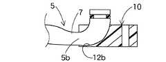
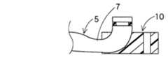
図1〜4は、配管部材5が配管継手10に接続されている状態を示すものであり、配管継手10は、冷凍装置の取り付けベース1にボルト2で固着されるとともに、配管部材5を挿通している。配管部材5は、配管継手10に支持されながら先端部5aに形成される溝6にOリング8を装着して取り付けベース1に取り付けられている。
【0029】
配管部材5は、アルミニウム、鉄、銅、真鍮、ステンレス鋼等の金属材料から形成され、先端部5aと先端部5aから直交する水平部5bとを有して略L字状に形成されるとともに水平部5bの先端部5aとの屈曲する付近に偏平部7が形成されている。偏平部7は、屈曲された付近の水平部5bを高さ方向(先端部5aの方向)に対して薄くなり水平部5bを横広がり状に大径となるように形成することによって、偏平されていない部位と略同一の断面積を有している。この形状は、後述の配管継手10の挿通孔12に形成される楕円状溝部12bの形状に沿って形成されることとなる。
【0030】
一方、配管継手10は、アルミニウム、鉄、銅、真鍮、ステンレス鋼等の金属材料から形成され、図5〜7に示すように、配管部材5を挿通する挿通孔12を形成している。挿通孔12は、取り付けベース1の接続孔3に向かって形成される垂直部12aと垂直部12aと直交する方向に形成される水平部12bを有して縦方向断面が略L字状(図5参照)に形成されている。
【0031】
なお、配管継手10の挿通孔12は、配管部材5を挿通するために平面視において一端面から切り欠くように長溝状(図6参照)に形成され、垂直部12aから水平部5bに向かって、挿通孔12断面が先端部5aの真円から垂直部12bの楕円状に緩やかに移行するように形成されている。又、配管継手10の他端部にはボルト2を挿通するためのボルト通し孔13が形成されている。
【0032】
配管継手10の挿通孔12における水平部12bは、配管部材5の偏平部7を収納するために楕円状溝部12b(図7参照)として形成されている。楕円状溝部12bは、配管継手12の幅方向に対して垂直部12aから垂直部12bに向かって横広がりで、高さ方向に対して配管部材5の真円より小径となる楕円状に形成されている。
【0033】
従って、垂直部12aと溝部12bとを備える挿通孔12は、プレス機で配管部材5を配管継手10にカシメ圧着させる際に、配管部材5の屈曲又は偏平部7を形成するためのダイとして兼用して使用される。
【0034】
従って、上記の配管継手構造では、図1〜2に示すように、配管部材5を支持した配管継手10を冷凍装置の取り付けベース1に装着すると、配管部材5は配管継手10内に収納されることから、配管継手10に置ける取り付けベース1の反対側には、配管部材5は突出することなく構成でき、スペースを設けることができる。しかも、配管部材5の偏平部7は、配管継手10の溝部12bに収納できるとともに、溝部12bが配管継手10の厚み(配管継手高さともいう)Hより小さいことから、配管継手10の厚み自体を配管部材5の偏平部7以外の外径dより小さく形成することもできる。
【0035】
次に、上記の配管部材5を配管継手10に接続する手順について、図8〜10に基づいて説明する。この形態においては、予めL字状に屈曲された配管部材5を、偏平加工を行うと同時に配管継手10に固着して接続するものである。
【0036】
図8に示すように、図示しないプレス機に、配管継手10の取り付けベース3に対する取り付け面10aを上方に向け、L字状の配管部材5の先端部5aを上方に向けた状態で、配管継手10の上方に配管部材5を配置する。そして、図9に示すように、プレスパンチ15で配管部材5の水平部5bを配管継手10の挿通孔12における楕円状溝部12b側に向かってカシメ圧着すると、配管部材5は、図10に示すように、水平部5bにおいて、配管継手10の楕円状溝部12bに沿って楕円状に形成されて偏平部7を形成するともに、配管部材5自体が配管継手10に固着される。そして、配管部材5の先端部5aの溝6にOリング8を装着して、配管部材5を支持した配管継手10を取り付けベース1の接続孔3に装着する。なお、溝部6は、配管部材5を配管継手10にカシメ圧着した後に形成するようにしてもよい。
【0037】
又、ストレート状の配管部材5Aを加工する場合では、図11に示すように、図示しないプレス機に、配管継手10の取り付けベース3に対する取り付け面10aを上方に向け、ストレート状の配管部材5Aを水平方向に向けた状態で、配管継手10の上方に配管部材5Aを配置する。
【0038】
そして、プレスパンチ15で、配管部材5Aを配管継手10における挿通穴12の水平部12bに向かってカシメ圧着すると、図10に示すものと同様に、配管部材5Aは、先端部5aと水平部5bとを有する略L字状に曲げ加工されるとともに、配管部材5Aの水平部5bが、配管継手10の楕円状溝部12bに沿ってカシメ圧着されることから偏平状に形成され、さらに配管部材5Aは配管継手10に固着される。そして、前述と同様、配管部材5Aの先端部5aの溝6にOリング8を装着して、配管部材5Aを支持した配管継手10を取り付けベース1の接続孔3に装着する。
【0039】
上記のように、実施形態の配管継手構造では、冷凍装置の取り付けベース1の接続孔3に配管部材5を接続する際、配管継手5に垂直部12aと水平部12bを有して配管部材5を挿通するL字状の挿通孔12を形成するとともに、挿通孔12の水平部12bを横方向に広がる楕円状溝部12bとし、プレス機内に配管継手5の上方にL字状に曲げ加工された配管部材5を配置してプレスパンチ15で配管部材5を配管継手10に向かってカシメ圧着させる。この際、配管部材5の偏平加工と配管部材5と配管継手10との接続加工を同時に行うことによって、極めて短時間で配管部材5を配管継手10に接続することができる。
【0040】
また、ストレート状の配管部材5Aを加工する場合、偏平加工を行うと同時に配管部材の曲げ加工を行うことができることから、配管部材の曲げ加工を予め行う必要はなく、ストレート状の配管部材をはじめから加工できることとなる。
【0041】
従って、曲げ加工を予め行う工程を省略できることによって、さらに配管部材5Aを配管継手10に接続する加工時間を短縮することができる。
【0042】
しかも、配管部材5(又は5A)の偏平部7を配管継手10の楕円状溝部12bに収納できることから、配管継手10の取り付けベース1と反対側に配管部材5(又は5A)を突出することなく、スペースを作ることができ省スペース化を達成することができる。
【0043】
つまり、配管継手10に形成した楕円状溝部12bに配管部材5の偏平部7を収納することによって、配管部材5(又は5A)が配管継手10内を通ることとなって、お互いに隣接して重ね合わせることなく構成できることから、配管継手高さを小さくすることができる。
【0044】
しかも配管継手10に収納される配管部材5(又は5A)の偏平部7は、偏平されていない配管部材5(又は5A)の外径より高さ寸法が小さいことから、配管継手10の高さHを配管部材5(又は5A)の偏平されていない外径dより小さくすることができて、コンパクトな配管継手構造を提供することができる。
【0045】
次に第2の形態における配管部材と配管継手との接続方法では、予め偏平加工されたL字状の配管部材5、あるいはストレート状の配管部材5Aを、プレス機内に配置して配管継手10に接続するものである。
【0046】
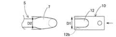
この方法では、図12に示すように、配管継手10の楕円状溝部12bの最大外径D1を配管部材5の偏平部7の最大外径D2より小さく形成して、配管部材5を配管継手10の挿通孔12上に配置した後、プレスパンチ15で上方からカシメ圧着させるか、あるいは、配管部材5を配管継手10の側方向に配置して、配管継手10の挿通孔12が形成されていない方向から配管部材5に向かってカシメ圧着する。これによって、配管部材5の偏平部7は、配管継手10の楕円状溝部12bに圧入されることとなって、配管部材5が配管継手10に接続される。
【0047】
又、図13に示すように、配管継手10の楕円状溝部12bの最大外径D1を配管部材5の偏平部7の最大外径D2より大きく形成して、配管部材5を配管継手10の挿通孔12に挿入した後、配管継手10の短手方向の両側面又は上下面から、プレス機でカシメ圧着する。これによって、配管部材5の外周周りに配管継手10の短手方向の両側壁部を巻き付けることとなって、配管部材5を配管継手10に接続することができる。
【0048】
さらに、別の形態では、図14〜16に示すように、L字状の配管部材5を配管継手10の挿通孔12に挿入した後、配管継手10の上面側に成形型18を配置させて配管部材5を配管継手10とともに支持させる。そして、液圧バルジ加工、つまり、油や水等の液体を配管部材5の先端部5a側から充填して圧力を掛けると、配管部材5の内部から液圧によって配管継手10の挿通穴12及び成形型18に向かって圧力が付与されて、配管部材5に偏平部7を形成するとともに配管継手10にカシメ圧着させる。
【0049】
従って、この形態においても、配管部材5に偏平部7を形成すると同時に配管部材5を配管継手10に接続することができ、短時間で行うことができる。
【0050】
なお、配管継手10を金属材料でなく、例えば、ナイロン、ポリプロピレン、ポリエチレン、エポキシ、ポリオキシメチレン、ポリフェニレンサルファイド、フェノール等の樹脂材料で形成して、前述の形態の成形方法によるプレス成形又は液圧バルジ成形あるいは樹脂インサート成形等で配管部材5を配管継手10に接続してもよい。
【0051】
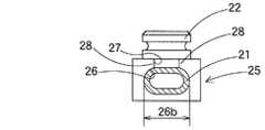
さらに、別の形態の配管継手構造は、図18〜20に示すように、偏平加工を施さない丸パイプ状の配管部材21を配管継手25に収納してプレス機でカシメ圧着するものである。
【0052】
配管部材21は、丸パイプ状に形成されるとともに、先端にシール溝23を有する継手部22を備えて形成され、継手部22が配管一般筒部21aより直交する方向に屈曲して形成されている。
【0053】
配管継手25は、配管部材21の挿通方向に対して長尺状に形成されるとともに、配管部材21を挿通する挿通孔部26を有している。挿通孔部26は、図18に示すように、水平方向に長円状に形成される水平部26aと、水平部26aから上面側に向かって緩やかな曲線部を有して断面略L字状に形成され、水平部26aの上面に開口部27を形成している。挿通孔部26の長円部26bは開口部27の幅寸法より幅広状に形成されて、開口部27に隣接する配管継手21の両側壁部は配管部材21を固定する固定部28・28として形成されている。
【0054】
上記のように形成された配管継手25に配管部材21を接続する際は、まず、開口部27を上面に向けて配置させ、外径を開口部27より僅かに小径に形成した一般筒部21a及び上方に屈曲した継手部22を、配管継手25の開口部27から挿通孔部26に収納する。この状態では、配管部材21は丸パイプ状に形成されていることから、配管継手25の挿通孔部26に収納した状態では、配管部材21の上面は開口部27内に突出し、さらに挿通孔部26の長円部26bに対して隙間を有して配置されている。
【0055】
そして、プレス機で配管継手25の開口部27側から配管部材21をカシメ圧着すると、配管部材21は長円状の挿通孔部26に倣って塑性変形するとともに配管継手25に固着される。この際、開口部27に隣接する配管継手25の固定部28が長円状に変形された配管部材21の上面を支持することとなって配管部材21を固定させる。配管部材21の継手部22は配管継手25の上面から突出して配置されることとなる。
【0056】
上述のように、カシメ圧着された配管部材21は、長円状の挿通孔部26と固定部28・28に圧着支持されるとともに、L字状に屈曲された継手部22がL字状に形成された挿通孔部26に収納されていることから、動きが規制されて配管継手25に接続することができる。
【0057】
従って、この形態においても、配管継手25の厚み範囲内に配管部材21の一般筒部21aを配置できることから、継手部22を除いて配管継手25の厚み以上にスペースをとることがなく省スペース化を達成することができる。しかも、配管部材21を配管継手25内に収納してプレス機でカシメ圧着するだけであることから、容易な作業で極めて短時間で配管部材21を配管継手25に接続することができる。
【0058】
また、図21〜23に示す形態の配管継手構造では、図18に示す形態の配管継手構造に対して、配管継手25の開口部27を、配管部材21の継手部22の突出方向と反対側に形成して配管部材21を下面側から挿入して収納している。
【0059】
つまり、配管部材21は、前述の形態と同様、一般筒部21aと、一般筒部21aの先端で一般筒部21aに直交する方向に屈曲する継手部22を備えている。一方、配管継手25は、水平方向に長円状に形成されるとともに長さ方向にL字状に形成された挿通孔部26と、挿通孔部26に対して屈曲された孔部と反対側の方向に軸心に沿って開口部27Aが形成されている。開口部27Aの両端の壁部は固定部28A・28Aとして形成されている。
【0060】
上記のように形成された配管継手25に配管部材21を接続する際は、まず、開口部27Aを図21の状態に対して上下反対方向の上面に向けて配置させ、外径を開口部27Aより僅かに小径に形成した一般筒部21a及び下方に屈曲した継手部22を、配管継手25の開口部27Aから挿通孔部26に収納する。
【0061】
そして、前述と同様に、プレス機で配管継手25の開口部27A側から配管部材21をカシメ圧着すると、配管部材21は長円状の挿通孔部26に倣って塑性変形するとともに配管継手25に固着される。この際、開口部27Aに隣接する配管継手25の固定部28Aが長円状に変形された配管部材21の上面を支持することとなって配管部材21を固定させる。配管部材21の継手部22は配管継手25から突出して配置されることとなる。
【0062】
従って、この形態においても、配管継手25の厚み範囲内に配管部材21の一般筒部21aを配置できることから、継手部22を除いて配管継手25の厚み以上にスペースをとることがなく省スペース化を達成することができる。しかも、配管部材21を配管継手25内に収納してプレス機でカシメ圧着するだけであることから、容易な作業で極めて短時間で配管部材21を配管継手25に接続することができる。
【図面の簡単な説明】
【図1】本発明の一形態による配管継手構造を示す簡略取り付け外観図である。
【図2】図1における簡略縦断面図である。
【図3】図2におけるIII−III断面図である。
【図4】図1におけるA矢視図である。
【図5】図2における配管継手を示す断面図である。
【図6】図5における配管継手の平面図である。
【図7】図5におけるVII−VII断面図である。
【図8】L字状の配管部材を配管継手に挿入する作用を示す断面図である。
【図9】図8の作用を示す簡略断面図である。
【図10】配管部材が配管継手に接続された作用を示す簡略断面図である。
【図11】ストレート状の配管部材を配管継手にカシメ圧着する方法を示す作用図である。
【図12】第2の形態の配管部材を配管継手に接続する方法を示す平面図である。
【図13】さらに別の形態で配管部材を配管継手に接続する方法を示す平面図である。
【図14】液圧バルジで配管部材を配管継手に接続する作用を示す簡略断面図である。
【図15】図14の作用を示す簡略断面図である。
【図16】図15によって接続された配管部材と配管継手を示す簡略断面図である。
【図17】従来の配管継手構造を示す断面図である。
【図18】別の形態による配管継手構造を示す断面図(図19におけるXVIII−XVIII断面図)である。
【図19】図18における平面図である。
【図20】図19におけるXX−XX断面図である。
【図21】さらに別の形態による配管継手構造を示す断面図(図22におけるXXI−XXI断面図)である。
【図22】図21における平面図である。
【図23】図22におけるXXIII−XXIII断面図である。
【符号の説明】
1 取り付けベース
3 接続孔
5、5A 配管部材
5a 先端部
5b 水平部
7 偏平部
10 配管継手
12 挿通孔
12a 垂直部
12b 水平部(楕円状溝部)
21 配管部材
25 配管継手
26 挿通孔部
26b 長円部
27、27A 開口部
28,28A 固定部[0001]
BACKGROUND OF THE INVENTION
The present invention particularly relates to a pipe joint structure in which a pipe member connected to a refrigeration apparatus of a vehicle air conditioner is supported by a pipe joint and a pipe joint connection method.
[0002]
[Prior art]
In general, when connecting a refrigerant pipe of a vehicle air conditioner to a pipe connection portion of each refrigeration apparatus, the refrigerant pipe is often supported and connected to a flange-like pipe joint fixedly screwed to each refrigeration apparatus. In this case, the pipe joint structure is formed by providing a refrigerant passage in the pipe joint and connecting the outlet of the refrigerant passage to the refrigerant inlet of the refrigeration apparatus, and then brazing the tip of the pipe member to the refrigerant passage inlet of the pipe joint. By doing so, the piping member and the piping joint were connected. However, in this pipe joint structure, since the pipe joint is formed in a complicated manner and the work of brazing itself takes time and costs are increased, it is performed without brazing described in
[0003]
[Patent Document 1]
Japanese Unexamined Patent Publication No. 2000-46259 (refer to
[0004]
[Problems to be solved by the invention]
However, in recent years, vehicle air conditioners are limited in space in the vehicle engine room, and since various equipment is arranged, space saving and cost reduction are required in order to secure space around the refrigeration cycle. It has become like this.
[0005]
In the conventional piping method disclosed in
[0006]
When piping to each refrigeration apparatus under space saving, in the pipe joint structure shown in
[0007]
However, in order to further secure the space on the pipe joint side, even when the pipe member is bent from one end of the pipe joint, the pipe method of the above-mentioned
[0008]
The present invention solves the above-described problems, and provides a pipe joint structure that is compactly configured so that the height dimension of the pipe joint can be made smaller than the outer diameter of the pipe member in order to further reduce the space. It is another object of the present invention to provide a pipe joint connection method that can connect a pipe joint and a pipe member in a short time.
[0009]
[Means for Solving the Problems]
In order to solve the above problems, the pipe joint structure according to the present invention isBook In the invention, the pipe joint structure supports the pipe member with the pipe joint, and when the pipe member that circulates the refrigerant is connected to the refrigeration apparatus, the flat part is formed in a part of the pipe member and the flat part is formed in the pipe joint. It is comprised so that the accommodating part which accommodates may be formed.
[0010]
In other words, by storing the flat portion of the piping member in the storage portion formed in the piping joint, the piping member passes through the piping joint and can be configured without being superposed adjacent to each other. The thickness can be reduced. Moreover, since the flat part of the pipe member housed in the pipe joint is smaller in height than the outer diameter of the non-flat pipe member, the pipe joint itself should be made smaller than the non-flat outer part of the pipe joint. And a compact pipe joint structure can be provided.
[0011]
Therefore, a space can be made on one side of the pipe joint, and further space saving can be achieved.
[0012]
Book According to the invention, since the flat portion of the piping member is formed in a portion that is bent in a direction orthogonal to the piping connection portion of the refrigeration apparatus, the piping member bent from the refrigeration apparatus connection portion of the piping member. The height of the outer peripheral surface can be reduced, and the height dimension of the pipe joint can also be reduced.
[0013]
In addition, when the piping member is supported by the piping joint and attached to the refrigeration apparatus, the bent portion of the piping member is stored in the storage portion of the piping joint, and the piping member is placed on one side of the piping joint. Will not protrude. Therefore, a space can be made on one side of the pipe joint, and space saving can be achieved.
[0014]
further,Book According to the invention, since the groove portion as the storage portion for storing the flat portion of the piping member is formed in the pipe joint, when the flat portion is formed in the bent portion of the piping member, the groove portion is a die. Thus, the flat portion can be formed in accordance with the shape of the groove portion. In addition, since the groove portion is formed in an elliptical shape extending in the lateral direction, the cross-sectional area of the flattened portion of the piping member can be formed substantially the same as the cross-sectional area of the other non-flattened portions. Does not disturb the smooth flow.
[0015]
or,Book The present invention is a connection method for connecting a pipe member to be piped to a refrigeration apparatus to a pipe joint in order to support the pipe member to be mounted on the refrigeration apparatus, and forming a storage portion for storing the flat portion in the pipe joint Then, the flat part of the pipe member can be formed in a part of the pipe member by simultaneously performing the flat process of the pipe member and the connecting process of connecting the flat part of the pipe member to the pipe joint.
[0016]
That is, before attaching the pipe joint to the refrigeration apparatus, place the flattened part of the straight pipe member or the bent pipe member above the storage part of the pipe joint, from the pipe member side toward the pipe joint, For example, when crimping is performed by a press machine, the piping member can be crimped to the housing portion formed in the pipe joint, and the flat portion can be formed. In this connection method, the piping member forms a flat portion and at the same time is integrally fixed to the piping joint.
[0017]
As a result, the piping member can be flattened and the piping member and the pipe joint can be connected in a very short time, and the flat part of the piping member can be stored in the storage part of the pipe joint. A space can be created without projecting the piping member, and space saving can be achieved.
[0018]
further,Book In the invention,above In addition to the invention, since the pipe member can be bent simultaneously with the flattening process, the pipe member need not be bent in advance, and the straight pipe member can be processed from the beginning.
[0019]
Therefore, the process of connecting the pipe member to the pipe joint can be further shortened by omitting the step of performing the bending process in advance.
[0020]
further,Book The invention relates to a connection method for connecting a pipe member to be piped to a refrigeration apparatus to a pipe joint in order to support the pipe member to be attached to the refrigeration apparatus, and a storage portion for storing the flat portion of the pipe member in the pipe joint. Forming and connecting the pipe member to the pipe joint at the same time or after storing the pipe member that has been flattened in advance in the pipe joint storage sectionThe By doing so, the piping member is supported by the piping joint.
[0021]
That is, in this pipe joint connection method, a pipe member that has been flattened in advance is connected to the pipe joint, and the pipe joint is formed with a storage portion that houses the pipe member. If the piping member is crimped by, for example, a press machine, the piping joint becomes a die, and the flat portion of the piping member can be corrected according to the shape of the piping joint housing portion, and the outer diameter of the piping joint housing portion By forming the shape smaller than the flat portion of the pipe member that has been flattened in advance, the pipe member is connected to the pipe joint when crimping with a press.
[0022]
Therefore, the piping member and the pipe joint can be connected in an extremely short time, and the flat part of the pipe member can be stored in the storage part of the pipe joint, so that a space can be saved without protruding the pipe member on one side of the pipe joint. It can be made and space saving can be achieved.
[0023]
At this time, if the pipe member is a straight pipe member that is not bent, the pipe member can be bent at the same time when the pipe member is connected to the pipe joint, and the processing time can be further reduced.
[0024]
or,Book The present invention relates to a connection method for connecting a pipe member to be piped to a refrigeration apparatus to a pipe joint in order to support the pipe member to be attached to the refrigeration apparatus, and the pipe joint is provided with an oval insertion hole portion. The member is formed to be insertable. An opening is formed in one of the insertion holes so that the piping member can be stored in the insertion hole. After the piping member is stored in the insertion hole, the piping member is crimped by the crimping means from the opening side. It is connected to a pipe joint.
[0025]
That is, when the piping member is housed in the insertion hole portion from the opening of the pipe joint and the opening is directed upward, for example, with a press, the piping member is formed in an oval shape in the horizontal direction. It is formed in an oval shape following the insertion hole. Since the oval portion of the insertion hole is formed to be wide with respect to the opening, the portion adjacent to the opening is formed as a fixing portion that supports the piping member. In this connection method, the piping member is integrally fixed to the piping joint even if the piping member has a round pipe shape.
[0026]
As a result, the piping member can be accommodated and connected to the piping joint in a very short time, and a space can be created without projecting the piping member on one side of the piping joint, thereby achieving space saving. .
[0027]
DETAILED DESCRIPTION OF THE INVENTION
Hereinafter, an embodiment of the present invention will be described with reference to the drawings.
[0028]
1 to 4 show a state in which the piping
[0029]
The piping
[0030]
On the other hand, the pipe joint 10 is made of a metal material such as aluminum, iron, copper, brass, and stainless steel, and forms an
[0031]
The
[0032]
The
[0033]
Accordingly, the
[0034]
Accordingly, in the above-described pipe joint structure, as shown in FIGS. 1 and 2, when the pipe joint 10 that supports the
[0035]
Next, a procedure for connecting the piping
[0036]
As shown in FIG. 8, in a press machine (not shown), the pipe joint with the
[0037]
Further, when processing the
[0038]
When the piping
[0039]
As described above, in the pipe joint structure of the embodiment, when the
[0040]
Further, when processing the
[0041]
Therefore, since the step of performing the bending process in advance can be omitted, the processing time for connecting the piping
[0042]
And since the
[0043]
That is, by accommodating the
[0044]
Moreover, since the
[0045]
Next, in the connection method between the piping member and the piping joint in the second embodiment, the L-shaped
[0046]
In this method, as shown in FIG. 12, the maximum outer diameter D <b> 1 of the
[0047]
Further, as shown in FIG. 13, the maximum outer diameter D1 of the
[0048]
Furthermore, in another form, as shown to FIGS. 14-16, after inserting the L-shaped
[0049]
Therefore, also in this embodiment, the
[0050]
Note that the pipe joint 10 is not made of a metal material, but is made of, for example, a resin material such as nylon, polypropylene, polyethylene, epoxy, polyoxymethylene, polyphenylene sulfide, phenol, and the like. The
[0051]
Furthermore, as shown in FIGS. 18 to 20, the pipe joint structure in another form is configured such that a round pipe-shaped
[0052]
The piping
[0053]
The pipe joint 25 is formed in an elongated shape with respect to the insertion direction of the
[0054]
When connecting the piping
[0055]
When the piping
[0056]
As described above, the caulking crimped piping
[0057]
Accordingly, even in this embodiment, the general
[0058]
Moreover, in the piping joint structure of the form shown to FIGS. 21-23, the opening
[0059]
That is, the piping
[0060]
When connecting the
[0061]
Then, as described above, when the piping
[0062]
Accordingly, even in this embodiment, the general
[Brief description of the drawings]
FIG. 1 is a simplified attachment external view showing a pipe joint structure according to an embodiment of the present invention.
FIG. 2 is a simplified longitudinal sectional view in FIG.
3 is a cross-sectional view taken along line III-III in FIG.
4 is a view taken in the direction of arrow A in FIG.
FIG. 5 is a cross-sectional view showing a pipe joint in FIG. 2;
6 is a plan view of the pipe joint in FIG. 5. FIG.
7 is a cross-sectional view taken along line VII-VII in FIG.
FIG. 8 is a cross-sectional view showing an operation of inserting an L-shaped pipe member into a pipe joint.
9 is a simplified cross-sectional view showing the operation of FIG.
FIG. 10 is a simplified cross-sectional view showing an operation in which a piping member is connected to a piping joint.
FIG. 11 is an operation diagram showing a method of crimping and crimping a straight pipe member to a pipe joint.
FIG. 12 is a plan view showing a method of connecting the piping member of the second embodiment to the piping joint.
FIG. 13 is a plan view showing a method of connecting a pipe member to a pipe joint in still another embodiment.
FIG. 14 is a simplified cross-sectional view showing the operation of connecting a piping member to a piping joint with a hydraulic bulge.
15 is a simplified cross-sectional view showing the operation of FIG.
16 is a simplified cross-sectional view showing a piping member and a piping joint connected according to FIG.
FIG. 17 is a cross-sectional view showing a conventional pipe joint structure.
18 is a cross-sectional view (XVIII-XVIII cross-sectional view in FIG. 19) showing a pipe joint structure according to another embodiment.
FIG. 19 is a plan view of FIG.
20 is a cross-sectional view taken along the line XX-XX in FIG.
FIG. 21 is a cross-sectional view (XXI-XXI cross-sectional view in FIG. 22) showing a pipe joint structure according to still another embodiment.
22 is a plan view of FIG. 21. FIG.
23 is a cross-sectional view taken along the line XXIII-XXIII in FIG.
[Explanation of symbols]
1 Mounting base
3 Connection hole
5, 5A Piping member
5a Tip
5b Horizontal part
7 Flat part
10 Piping joint
12 Insertion hole
12a Vertical section
12b Horizontal part (elliptical groove)
21 Piping members
25 Piping joint
26 Insertion hole
26b Ellipse
27, 27A opening
28, 28A fixed part
Claims (6)
Translated fromJapanese前記配管部材は、先端部とその先端部から直交する水平部とを有し、前記先端部と前記水平部との屈曲する付近に前記水平部を横広がり状に大径となるように形成することによって偏平部が形成されるとともに前記先端部が前記配管継手から突出して配置され、
前記配管継手に前記偏平部を収納する収納部を設けて前記冷凍装置に装着され、前記配管継手の収納部が、前記配管継手の幅方向に対して横広がり状の楕円状に形成された溝部として形成されていることを特徴とする配管継手構造。A pipe joint structure for supporting a pipe member to be piped to a refrigerating apparatus of an air conditioner with a pipe joint,
The piping member has a distal end portion and a horizontal portion orthogonal to the distal end portion, and the horizontal portion is formed to have a large diameter so as to spread laterally in the vicinity of the bending between the distal end portion and the horizontal portion. By this, a flat part is formed and the tip part is arranged to protrude from the pipe joint,
The pipe joint is provided with a storage part for storing the flat part and attached to the refrigeration apparatus, and the storage part of thepipe joint is formed inan elliptical shape thatextends in the width direction of the pipe joint. A pipe joint structure characterized by being formed as:
前記配管部材は、先端部とその先端部から直交する水平部とを有し、前記先端部と前記水平部との屈曲する付近に前記水平部を横広がり状に大径となるように形成することによって偏平部が形成されるとともに前記先端部が前記配管継手から突出して配置され、
前記配管継手に、前記偏平部を収納するとともに前記配管継手の幅方向に対して横広がり状の楕円状に形成された溝部として形成された収納部が配置され、前記配管継手が前記冷凍装置に装着され、前記配管部材の偏平部が、前記冷凍装置の取り付け方向に対して直交する方向に屈曲する部位に形成されていることを特徴とする配管継手構造。A pipe joint structure for supporting a pipe member to be piped to a refrigerating apparatus of an air conditioner with a pipe joint,
The piping member has a distal end portion and a horizontal portion orthogonal to the distal end portion, and the horizontal portion is formed to have a large diameter so as to spread laterally in the vicinity of the bending between the distal end portion and the horizontal portion. By this, a flat part is formed and the tip part is arranged to protrude from the pipe joint,
In the pipe joint ,the flat part is stored,and a storage part formed as a groove part that is formed in an elliptical shape extending laterally with respect to the width direction of the pipe joint is disposed, and the pipe joint is connected to the refrigeration apparatus. A pipe joint structure, wherein the pipe joint structure is mounted and is formed in a portion that bends in a direction orthogonal to the attachment direction of the refrigeration apparatus.
前記配管部材は、先端部とその先端部から直交する水平部とを有し、前記先端部と前記水平部との屈曲する付近に前記水平部を横広がり状に大径となるように形成することによって偏平部が形成されるとともに前記先端部が前記配管継手から突出して配置され、
前記配管継手に、前記偏平部を収納するとともに前記配管継手の幅方向に対して横広がり状の楕円状に形成された溝部として形成された収納部が配置され、
前記配管部材の偏平加工と、前記配管部材の偏平部を前記配管継手に接続する接続加工とを同時に行うことを特徴とする配管継手の接続方法。A pipe joint connecting method for supporting a pipe member to be piped to a refrigeration apparatus of an air conditioner with a pipe joint attached to the refrigeration apparatus,
The piping member has a distal end portion and a horizontal portion orthogonal to the distal end portion, and the horizontal portion is formed to have a large diameter so as to spread laterally in the vicinity of the bending between the distal end portion and the horizontal portion. By this, a flat part is formed and the tip part is arranged to protrude from the pipe joint,
In the pipe joint, the storage part formed as a groove part that is formed in an elliptical shape extending in the transverse direction with respect to the width direction of the pipe joint and storing the flat part is disposed,
A method for connecting pipe joints, wherein the flat processing of the pipe member and the connection processing for connecting the flat portion of the pipe member to the pipe joint are performed simultaneously .
前記配管部材は、先端部とその先端部から直交する水平部とを有し、前記先端部と前記水平部との屈曲する付近に前記水平部を横広がり状に大径となるように形成することによって偏平部が形成されるとともに前記先端部が前記配管継手から突出して配置され、
前記配管継手に、前記偏平部を収納するとともに前記配管継手の幅方向に対して横広がり状の楕円状に形成された溝部として形成された収納部が配置され、
予め偏平加工された前記配管部材を、前記配管継手の収納部に挿入すると同時に、又は、挿入後に圧着して前記配管継手に接続することを特徴とする配管継手の接続方法。A pipe joint connecting method for supporting a pipe member to be piped to a refrigeration apparatus of an air conditioner with a pipe joint attached to the refrigeration apparatus,
The piping member has a distal end portion and a horizontal portion orthogonal to the distal end portion, and the horizontal portion is formed to have a large diameter so as to spread laterally in the vicinity of the bending between the distal end portion and the horizontal portion. By this, a flat part is formed and the tip part is arranged to protrude from the pipe joint,
In the pipe joint, the storage part formed as a groove part that is formed in an elliptical shape extending in the transverse direction with respect to the width direction of the pipe joint and storing the flat part is disposed,
A pipe joint connection methodcomprising: connecting the pipe member that has been flattened in advance to the pipe joint by being crimped at the same time as or after being inserted into the pipe joint housing .
前記配管部材は、先端部とその先端部から直交する水平部とを有し、前記先端部と前記水平部との屈曲する付近に前記水平部を横広がり状に大径となるように形成することによって偏平部が形成されるとともに前記先端部が前記配管継手から突出して配置され、
前記配管継手には、前記配管部材を挿通する水平方向に長円状の挿通孔部が形成され、前記挿通孔部には、前記配管部材を挿入するための開口部が形成され、前記配管部材を前記開口部側から前記挿通孔部に収納した後、前記配管部材を前記開口部側から圧着手段で圧着して前記配管部材を長円状に変形させることによって、前記開口部に隣接する前記配管継手の固定部で前記配管部材を固定支持することを特徴とする配管継手の接続方法。A pipe joint connection method for supporting a pipe member piped to a refrigerating apparatus of an air conditioner with a pipe joint,
The piping member has a distal end portion and a horizontal portion orthogonal to the distal end portion, and the horizontal portion is formed to have a large diameter so as to spread laterally in the vicinity of the bending between the distal end portion and the horizontal portion. By this, a flat part is formed and the tip part is arranged to protrude from the pipe joint,
The pipe joint is formed with an oval insertion hole in the horizontal direction through which the pipe member is inserted, and the insertion hole is formed withan opening for inserting the pipe member. Is stored in the insertion hole from the opening side, and then the piping member is crimped by a crimping means from the opening side to deform the piping member into an oval shape, thereby adjoining the opening. A pipe joint connection method, wherein the pipe member is fixedly supported by a fixing portion of the pipe joint.
Priority Applications (5)
| Application Number | Priority Date | Filing Date | Title |
|---|---|---|---|
| JP2003077900AJP3956878B2 (en) | 2002-09-03 | 2003-03-20 | Piping joint structure and piping joint connection method |
| CNB031577296ACN1221753C (en) | 2002-09-03 | 2003-08-28 | Pipe and joint-connection structure and connection method thereof |
| DE10340179ADE10340179A1 (en) | 2002-09-03 | 2003-09-01 | Connection structure for a pipe and a pipe connection and method for connecting a pipe and a pipe connection |
| US10/653,560US7007981B2 (en) | 2002-09-03 | 2003-09-02 | Connecting structure of pipe and pipe joint and method of connecting the pipe to the pipe joint |
| FR0310433AFR2844027B1 (en) | 2002-09-03 | 2003-09-03 | CONNECTING STRUCTURE OF PIPE AND PIPE SEAL AND METHOD OF CONNECTING PIPE TO PIPE JOINT |
Applications Claiming Priority (2)
| Application Number | Priority Date | Filing Date | Title |
|---|---|---|---|
| JP2002257672 | 2002-09-03 | ||
| JP2003077900AJP3956878B2 (en) | 2002-09-03 | 2003-03-20 | Piping joint structure and piping joint connection method |
Publications (2)
| Publication Number | Publication Date |
|---|---|
| JP2004150788A JP2004150788A (en) | 2004-05-27 |
| JP3956878B2true JP3956878B2 (en) | 2007-08-08 |
Family
ID=31719902
Family Applications (1)
| Application Number | Title | Priority Date | Filing Date |
|---|---|---|---|
| JP2003077900AExpired - Fee RelatedJP3956878B2 (en) | 2002-09-03 | 2003-03-20 | Piping joint structure and piping joint connection method |
Country Status (5)
| Country | Link |
|---|---|
| US (1) | US7007981B2 (en) |
| JP (1) | JP3956878B2 (en) |
| CN (1) | CN1221753C (en) |
| DE (1) | DE10340179A1 (en) |
| FR (1) | FR2844027B1 (en) |
Families Citing this family (13)
| Publication number | Priority date | Publication date | Assignee | Title |
|---|---|---|---|---|
| GB0402206D0 (en)* | 2004-02-02 | 2004-03-03 | Eaton Corp | Method and structure for retaining a tube |
| DE102006013002A1 (en)* | 2006-05-20 | 2007-11-22 | Zf Lenksysteme Gmbh | Fluid line connection for use in e.g. brake system, has fluid line secured in base in form fit manner by retaining unit, where retaining unit is assembled in and/or on base in direction running perpendicular to connecting surface |
| DE102007017693A1 (en)* | 2007-04-14 | 2008-10-16 | Zf Lenksysteme Gmbh | Device for connecting pipes fixes pipes inserted into pipe connectors using a holding plate |
| JP5012476B2 (en) | 2007-12-11 | 2012-08-29 | 株式会社デンソー | Manufacturing method of refrigerant piping |
| JP2011106607A (en)* | 2009-11-19 | 2011-06-02 | Sanoh Industrial Co Ltd | Pipe connecting structure |
| CN102950217B (en)* | 2011-08-29 | 2015-08-12 | 珠海格力电器股份有限公司 | Method for forming special-shaped pipe end and special-shaped clamping die used by same |
| US20140202577A1 (en)* | 2013-01-21 | 2014-07-24 | William Gardiner WEBSTER, III | Duct fitting apparatus with reduced flow pressure loss and method of formation thereof |
| GB2520501A (en)* | 2013-11-20 | 2015-05-27 | Eaton Ind Ip Gmbh & Co Kg | Tube fastener assembly and method for fastening a tube to a tube fastener assembly |
| JP6939193B2 (en)* | 2017-07-27 | 2021-09-22 | 株式会社オンダ製作所 | Resin elbow fittings and piping covers |
| CN108006345A (en)* | 2017-12-25 | 2018-05-08 | 上海加冷松芝汽车空调股份有限公司 | A kind of pipe element |
| US20200200307A1 (en)* | 2018-12-21 | 2020-06-25 | Hanon Systems | Metal seal fitting with tight bend technology |
| JP7668613B2 (en)* | 2019-02-04 | 2025-04-25 | エドワーズ株式会社 | Vacuum pump |
| CN112178335B (en)* | 2020-09-29 | 2021-11-30 | 中国航发动力股份有限公司 | Fuel manifold adapter and use method thereof |
Family Cites Families (28)
| Publication number | Priority date | Publication date | Assignee | Title |
|---|---|---|---|---|
| US115785A (en)* | 1871-06-06 | Improvement in elbows for hot-air pipes | ||
| US1215451A (en)* | 1915-04-19 | 1917-02-13 | William M White | Hydraulic equalizer. |
| US1737633A (en)* | 1928-01-13 | 1929-12-03 | Internat Radiator Corp | Heating unit |
| US3764647A (en)* | 1970-08-10 | 1973-10-09 | Gen Motors Corp | Method of assembling universal joint yoke and spider |
| US3844586A (en)* | 1973-02-20 | 1974-10-29 | Selfix Inc | Faucet connector |
| US3880416A (en)* | 1973-11-05 | 1975-04-29 | Don A Horwitz | Fixture assembly for the repair of universal joints |
| CH614275A5 (en)* | 1976-02-03 | 1979-11-15 | Sulzer Ag | |
| US5044674A (en)* | 1990-08-03 | 1991-09-03 | Quikcoup, Inc. | Angularly adjustable pipe connector |
| US5227304A (en)* | 1991-01-16 | 1993-07-13 | Sequoia Turner Corporation | Method for counting whole blood diluent and detergent reagent system |
| IT1252387B (en)* | 1991-11-12 | 1995-06-12 | Telettra S P A Ora Alcatel Ita | FLANGES AND BODIES FOR MICROWAVE WAVE GUIDE COMPONENTS |
| US5397272A (en)* | 1993-02-08 | 1995-03-14 | Pressure Technology, Inc. | Braided composite shaft with yoke member |
| JP3344002B2 (en) | 1993-06-21 | 2002-11-11 | 株式会社デンソー | Refrigerant piping connection fitting |
| JPH0875074A (en)* | 1994-09-07 | 1996-03-19 | Kayaba Ind Co Ltd | Suction connector for pump |
| US5632685A (en)* | 1995-12-04 | 1997-05-27 | Dana Corporation | End fitting for drive shaft assembly and method of manufacturing same |
| US5853201A (en) | 1996-01-17 | 1998-12-29 | Nippondenso Co., Ltd. | Coolant pipe connecting coupling |
| DE69809978T2 (en)* | 1997-02-19 | 2003-08-28 | Yordak Ltd., Haifa | Constant velocity universal joint |
| US6149506A (en)* | 1998-10-07 | 2000-11-21 | Keltech Engineering | Lapping apparatus and method for high speed lapping with a rotatable abrasive platen |
| US5733145A (en)* | 1997-03-13 | 1998-03-31 | Tescorp Seismic Products, Inc. | Seal assembly for overmolded metal structure |
| JP3956495B2 (en) | 1998-07-27 | 2007-08-08 | 株式会社デンソー | Piping joint and manufacturing method thereof |
| US6209319B1 (en)* | 1998-09-28 | 2001-04-03 | Honda Giken Kogyo Kabushiki Kaisha | Pipe assembly having inner and outer pipes |
| US6135667A (en)* | 1998-10-20 | 2000-10-24 | The Torrington Company | Expanding clamp for slap yoke |
| JP2001046259A (en) | 1999-08-06 | 2001-02-20 | Inax Corp | Soundproof structure for bathtub |
| US6318765B1 (en)* | 1999-10-29 | 2001-11-20 | Automotive Fluid Systems, Inc. | Serviceable mounting device for conduit |
| US6422947B1 (en)* | 2000-02-11 | 2002-07-23 | Visteon Global Technologies, Inc. | Driveshaft bearing assembly |
| FR2805330B1 (en) | 2000-02-23 | 2002-11-29 | Manuli Auto France | CONNECTION ASSEMBLY BETWEEN A RIGID CYLINDRICAL TUBE BENDED AT ITS END AND A PART, AND CORRESPONDING CONNECTION METHOD |
| US6348002B1 (en)* | 2000-02-24 | 2002-02-19 | Spicer Driveshaft, Inc. | Slip yoke sealing and positioning plug |
| JP2001248773A (en) | 2000-03-02 | 2001-09-14 | Zexel Valeo Climate Control Corp | Piping joint, adapter for joint, and method for connecting piping with pipe joint |
| US6367680B1 (en)* | 2000-08-10 | 2002-04-09 | Spicer Driveshaft, Inc. | Component for vehicular driveshaft assembly and method of manufacturing same |
- 2003
- 2003-03-20JPJP2003077900Apatent/JP3956878B2/ennot_activeExpired - Fee Related
- 2003-08-28CNCNB031577296Apatent/CN1221753C/ennot_activeExpired - Fee Related
- 2003-09-01DEDE10340179Apatent/DE10340179A1/ennot_activeWithdrawn
- 2003-09-02USUS10/653,560patent/US7007981B2/ennot_activeExpired - Lifetime
- 2003-09-03FRFR0310433Apatent/FR2844027B1/ennot_activeExpired - Fee Related
Also Published As
| Publication number | Publication date |
|---|---|
| FR2844027B1 (en) | 2005-09-30 |
| FR2844027A1 (en) | 2004-03-05 |
| CN1488876A (en) | 2004-04-14 |
| DE10340179A1 (en) | 2004-03-11 |
| US7007981B2 (en) | 2006-03-07 |
| US20040041396A1 (en) | 2004-03-04 |
| JP2004150788A (en) | 2004-05-27 |
| CN1221753C (en) | 2005-10-05 |
Similar Documents
| Publication | Publication Date | Title |
|---|---|---|
| JP3956878B2 (en) | Piping joint structure and piping joint connection method | |
| US5036914A (en) | Vehicle-loaded parallel flow type heat exchanger | |
| JP2004036944A (en) | Piping joint structure and its manufacturing method | |
| US8141911B2 (en) | Pipe connection joint | |
| US6928732B2 (en) | Method of manufacturing piping having joining portion | |
| JP2008275260A (en) | Heat exchanger and method of manufacturing connector used for its heat exchanger | |
| CN105972283B (en) | Valve body, slidingtype switching valve and the air conditioner of slidingtype switching valve | |
| JP2006132653A (en) | Double pipe, its manufacturing method, and supporting member of double pipe | |
| US5771965A (en) | Header pipe for heat exchanger | |
| US7344164B2 (en) | Pipe connection structure | |
| US20090145152A1 (en) | Refrigerant piping unit and method of manufacturing pipe for the same | |
| JP2006242299A (en) | Pipe member with joint part and its manufacturing method | |
| US20060185167A1 (en) | Mechanical method for joining of tubular member to a plate member | |
| US4955210A (en) | Capillary tube assembly and method of manufacture | |
| JPH07125529A (en) | Manufacture of pipe joint | |
| US20070181293A1 (en) | Heat exchanger and producing method thereof | |
| KR100855707B1 (en) | Receiver dryer tank, manufacturing method and manufacturing apparatus | |
| JP2000218322A (en) | Method of manufacturing metallic bent pipe and metallic bent pipe | |
| JP5124104B2 (en) | Manufacturing method of piping members | |
| JP2001116480A (en) | Fin-coil type heat exchanger and method for manufacturing it | |
| KR101695642B1 (en) | Pipe connection joint | |
| CN220378478U (en) | Compressor and refrigeration equipment | |
| US6991264B2 (en) | Compressor and method of connecting pipe to the same | |
| JP2005207463A (en) | Connecting structure of passages | |
| JP3213567B2 (en) | Silencer for air conditioner |
Legal Events
| Date | Code | Title | Description |
|---|---|---|---|
| A621 | Written request for application examination | Free format text:JAPANESE INTERMEDIATE CODE: A621 Effective date:20050427 | |
| A977 | Report on retrieval | Free format text:JAPANESE INTERMEDIATE CODE: A971007 Effective date:20060920 | |
| A131 | Notification of reasons for refusal | Free format text:JAPANESE INTERMEDIATE CODE: A131 Effective date:20061003 | |
| A521 | Written amendment | Free format text:JAPANESE INTERMEDIATE CODE: A523 Effective date:20061127 | |
| A131 | Notification of reasons for refusal | Free format text:JAPANESE INTERMEDIATE CODE: A131 Effective date:20070116 | |
| A521 | Written amendment | Free format text:JAPANESE INTERMEDIATE CODE: A523 Effective date:20070309 | |
| TRDD | Decision of grant or rejection written | ||
| A01 | Written decision to grant a patent or to grant a registration (utility model) | Free format text:JAPANESE INTERMEDIATE CODE: A01 Effective date:20070417 | |
| A61 | First payment of annual fees (during grant procedure) | Free format text:JAPANESE INTERMEDIATE CODE: A61 Effective date:20070430 | |
| R150 | Certificate of patent or registration of utility model | Ref document number:3956878 Country of ref document:JP Free format text:JAPANESE INTERMEDIATE CODE: R150 Free format text:JAPANESE INTERMEDIATE CODE: R150 | |
| FPAY | Renewal fee payment (event date is renewal date of database) | Free format text:PAYMENT UNTIL: 20110518 Year of fee payment:4 | |
| FPAY | Renewal fee payment (event date is renewal date of database) | Free format text:PAYMENT UNTIL: 20120518 Year of fee payment:5 | |
| FPAY | Renewal fee payment (event date is renewal date of database) | Free format text:PAYMENT UNTIL: 20120518 Year of fee payment:5 | |
| FPAY | Renewal fee payment (event date is renewal date of database) | Free format text:PAYMENT UNTIL: 20130518 Year of fee payment:6 | |
| FPAY | Renewal fee payment (event date is renewal date of database) | Free format text:PAYMENT UNTIL: 20140518 Year of fee payment:7 | |
| R250 | Receipt of annual fees | Free format text:JAPANESE INTERMEDIATE CODE: R250 | |
| R250 | Receipt of annual fees | Free format text:JAPANESE INTERMEDIATE CODE: R250 | |
| S802 | Written request for registration of partial abandonment of right | Free format text:JAPANESE INTERMEDIATE CODE: R311802 | |
| R350 | Written notification of registration of transfer | Free format text:JAPANESE INTERMEDIATE CODE: R350 | |
| R250 | Receipt of annual fees | Free format text:JAPANESE INTERMEDIATE CODE: R250 | |
| R250 | Receipt of annual fees | Free format text:JAPANESE INTERMEDIATE CODE: R250 | |
| R250 | Receipt of annual fees | Free format text:JAPANESE INTERMEDIATE CODE: R250 | |
| LAPS | Cancellation because of no payment of annual fees |