JP3955344B2 - Manufacturing method of capacitor in semiconductor device - Google Patents
Manufacturing method of capacitor in semiconductor deviceDownload PDFInfo
- Publication number
- JP3955344B2 JP3955344B2JP21217296AJP21217296AJP3955344B2JP 3955344 B2JP3955344 B2JP 3955344B2JP 21217296 AJP21217296 AJP 21217296AJP 21217296 AJP21217296 AJP 21217296AJP 3955344 B2JP3955344 B2JP 3955344B2
- Authority
- JP
- Japan
- Prior art keywords
- layer
- doped
- capacitor
- highly doped
- conducting
- Prior art date
- Legal status (The legal status is an assumption and is not a legal conclusion. Google has not performed a legal analysis and makes no representation as to the accuracy of the status listed.)
- Expired - Fee Related
Links
- 239000003990capacitorSubstances0.000titleclaimsdescription82
- 239000004065semiconductorSubstances0.000titleclaimsdescription19
- 238000004519manufacturing processMethods0.000titleclaimsdescription7
- 238000000034methodMethods0.000claimsdescription28
- 238000005530etchingMethods0.000claimsdescription27
- 238000000151depositionMethods0.000claimsdescription16
- 230000008021depositionEffects0.000claimsdescription12
- 239000000758substrateSubstances0.000claimsdescription12
- VYPSYNLAJGMNEJ-UHFFFAOYSA-NSilicium dioxideChemical compoundO=[Si]=OVYPSYNLAJGMNEJ-UHFFFAOYSA-N0.000claimsdescription8
- 239000004020conductorSubstances0.000claimsdescription8
- 229910052814silicon oxideInorganic materials0.000claimsdescription8
- 229910052581Si3N4Inorganic materials0.000claimsdescription6
- -1boron fluoride ionsChemical class0.000claimsdescription6
- 239000000463materialSubstances0.000claimsdescription6
- HQVNEWCFYHHQES-UHFFFAOYSA-Nsilicon nitrideChemical compoundN12[Si]34N5[Si]62N3[Si]51N64HQVNEWCFYHHQES-UHFFFAOYSA-N0.000claimsdescription6
- KWYUFKZDYYNOTN-UHFFFAOYSA-MPotassium hydroxideChemical compound[OH-].[K+]KWYUFKZDYYNOTN-UHFFFAOYSA-M0.000claimsdescription5
- 238000010438heat treatmentMethods0.000claimsdescription4
- 230000015572biosynthetic processEffects0.000claimsdescription3
- 239000003795chemical substances by applicationSubstances0.000claimsdescription3
- 238000005468ion implantationMethods0.000claimsdescription3
- 150000004767nitridesChemical class0.000claimsdescription2
- YCIMNLLNPGFGHC-UHFFFAOYSA-NcatecholChemical compoundOC1=CC=CC=C1OYCIMNLLNPGFGHC-UHFFFAOYSA-N0.000claims2
- 229910015900BF3Inorganic materials0.000claims1
- 229910021420polycrystalline siliconInorganic materials0.000description23
- 229920005591polysiliconPolymers0.000description23
- 210000004027cellAnatomy0.000description13
- 239000000243solutionSubstances0.000description10
- XUIMIQQOPSSXEZ-UHFFFAOYSA-NSiliconChemical compound[Si]XUIMIQQOPSSXEZ-UHFFFAOYSA-N0.000description8
- 229910052710siliconInorganic materials0.000description8
- 239000010703siliconSubstances0.000description8
- 229910052796boronInorganic materials0.000description7
- 238000003860storageMethods0.000description6
- 238000002513implantationMethods0.000description5
- 238000000059patterningMethods0.000description4
- WFKWXMTUELFFGS-UHFFFAOYSA-NtungstenChemical compound[W]WFKWXMTUELFFGS-UHFFFAOYSA-N0.000description4
- 229910052721tungstenInorganic materials0.000description4
- 239000010937tungstenSubstances0.000description4
- RTAQQCXQSZGOHL-UHFFFAOYSA-NTitaniumChemical compound[Ti]RTAQQCXQSZGOHL-UHFFFAOYSA-N0.000description3
- NRTOMJZYCJJWKI-UHFFFAOYSA-NTitanium nitrideChemical compound[Ti]#NNRTOMJZYCJJWKI-UHFFFAOYSA-N0.000description3
- 239000011521glassSubstances0.000description3
- 229910052751metalInorganic materials0.000description3
- 239000002184metalSubstances0.000description3
- 238000004151rapid thermal annealingMethods0.000description3
- 229910052715tantalumInorganic materials0.000description3
- GUVRBAGPIYLISA-UHFFFAOYSA-Ntantalum atomChemical compound[Ta]GUVRBAGPIYLISA-UHFFFAOYSA-N0.000description3
- 239000010936titaniumSubstances0.000description3
- 229910052719titaniumInorganic materials0.000description3
- ZOXJGFHDIHLPTG-UHFFFAOYSA-NBoronChemical compound[B]ZOXJGFHDIHLPTG-UHFFFAOYSA-N0.000description2
- 239000005380borophosphosilicate glassSubstances0.000description2
- 238000009792diffusion processMethods0.000description2
- 239000000945fillerSubstances0.000description2
- 238000002347injectionMethods0.000description2
- 239000007924injectionSubstances0.000description2
- 239000012212insulatorSubstances0.000description2
- 150000002500ionsChemical class0.000description2
- 238000009825accumulationMethods0.000description1
- 230000004913activationEffects0.000description1
- 239000012670alkaline solutionSubstances0.000description1
- 229910052785arsenicInorganic materials0.000description1
- RQNWIZPPADIBDY-UHFFFAOYSA-Narsenic atomChemical compound[As]RQNWIZPPADIBDY-UHFFFAOYSA-N0.000description1
- 238000005234chemical depositionMethods0.000description1
- 238000006243chemical reactionMethods0.000description1
- 238000005516engineering processMethods0.000description1
- 238000005243fluidizationMethods0.000description1
- 238000011065in-situ storageMethods0.000description1
- 230000010354integrationEffects0.000description1
- 238000003475laminationMethods0.000description1
- 239000007791liquid phaseSubstances0.000description1
- 238000004518low pressure chemical vapour depositionMethods0.000description1
- 238000001451molecular beam epitaxyMethods0.000description1
- 230000003647oxidationEffects0.000description1
- 238000007254oxidation reactionMethods0.000description1
- 230000001590oxidative effectEffects0.000description1
- 238000004806packaging method and processMethods0.000description1
- 238000007517polishing processMethods0.000description1
- 229910021332silicideInorganic materials0.000description1
- FVBUAEGBCNSCDD-UHFFFAOYSA-Nsilicide(4-)Chemical compound[Si-4]FVBUAEGBCNSCDD-UHFFFAOYSA-N0.000description1
- 239000000126substanceSubstances0.000description1
- 238000007669thermal treatmentMethods0.000description1
- 239000012808vapor phaseSubstances0.000description1
Images


Classifications
- H—ELECTRICITY
- H10—SEMICONDUCTOR DEVICES; ELECTRIC SOLID-STATE DEVICES NOT OTHERWISE PROVIDED FOR
- H10B—ELECTRONIC MEMORY DEVICES
- H10B12/00—Dynamic random access memory [DRAM] devices
- H10B12/01—Manufacture or treatment
- H10B12/02—Manufacture or treatment for one transistor one-capacitor [1T-1C] memory cells
- H10B12/03—Making the capacitor or connections thereto
- H10B12/033—Making the capacitor or connections thereto the capacitor extending over the transistor
- H—ELECTRICITY
- H10—SEMICONDUCTOR DEVICES; ELECTRIC SOLID-STATE DEVICES NOT OTHERWISE PROVIDED FOR
- H10B—ELECTRONIC MEMORY DEVICES
- H10B12/00—Dynamic random access memory [DRAM] devices
- H10B12/30—DRAM devices comprising one-transistor - one-capacitor [1T-1C] memory cells
- H10B12/31—DRAM devices comprising one-transistor - one-capacitor [1T-1C] memory cells having a storage electrode stacked over the transistor
- H10B12/318—DRAM devices comprising one-transistor - one-capacitor [1T-1C] memory cells having a storage electrode stacked over the transistor the storage electrode having multiple segments
Landscapes
- Engineering & Computer Science (AREA)
- Manufacturing & Machinery (AREA)
- Semiconductor Memories (AREA)
- Semiconductor Integrated Circuits (AREA)
Description
Translated fromJapanese【0001】
【発明の属する技術分野】
本発明は、接続パターンにより上下に電気的に接続され互いに間隔をおいて配設されている複数の素子を含む電極パターン、コンデンサ誘電体及び対向電極を有する半導体装置、特にDRAM記憶装置内のコンデンサに関する。更に本発明は半導体装置内のコンデンサの製造方法に関する。
【0002】
【従来の技術】
多くの集積回路はコンデンサを必要とする。ダイナミックメモリセルの典型的な例の他にアナログ−ディジタル変換器又はディジタル−アナログ変換器及びフィルタ回路が考えられる。特に集積密度を高め又はチップ面を節約しなければならないことからパターンの微細化にはコンデンサの大きな所要面積を削減する措置が必要となる。この場合典型的な例としてはダイナミック半導体記憶装置があり、その際通常使用される1トランジスタメモリセルに必要な面積はメモリ世代からメモリ世代へ記憶密度が増すにつれて削減される。同時に記憶コンデンサの最小容量は維持されなければならない。
【0003】
ダイナミック半導体記憶装置の場合1トランジスタメモリセルは1個の読出しトランジスタと1個のコンデンサを含む。読出しトランジスタをワード線を介して操作することにより、コンデンサ内に記憶された情報即ち電荷はビット線を介して読出される。電荷の確実な蓄積及び読出された情報の同時識別のため記憶コンデンサは最小容量を有していなければならない。記憶コンデンサの容量に対する下限は従来20fFとされている。このコンデンサ容量を達成するには誘電体の厚さをできるだけ薄くまたコンデンサの面積をできるだけ大きくしなければならない。
【0004】
読出しトランジスタもコンデンサも1Mビットのメモリ世代まではプレーナデバイスとして形成されてきたが、4Mビットまでのメモリ世代からはコンデンサがトレンチ内に配設されている(トレンチキャパシタ)装置が知られている。このコンデンサの電極はトレンチの表面に沿って配設される。全体として基板の表面のプレーナ配置に比べてコンデンサの有効面積は拡大されている。
【0005】
コンデンサの所要面積をそのままにするか又は削減した場合にコンデンサの容量を拡大するもう1つの可能性は、コンデンサを積層コンデンサとして形成することにある。その際ワード線の上方にポリシリコンからなるパターン、例えば冠状パターン又は円筒状パターンが形成され、基板と接触化される。このポリシリコンパターンはコンデンサ誘電体及びコンデンサ板、いわゆるセル板を備えられているメモリの節を形成する。この構想は論理プロセスと両立できるという利点がある。
【0006】
コンデンサに対しては基板表面の上方の自由空間を利用できる。その際隣接するメモリセルのパターンが互いに分離されている限り全てのセル面をポリシリコンパターンにより覆うことができる。これに関してはフィン形積層キャパシタ及びクラウン形積層キャパシタが公知である。
【0007】
欧州特許出願公開第0415530号明細書から記憶コンデンサとして積層コンデンサを有する半導体記憶装置が公知である。積層コンデンサは、ほぼ並列に上下に配設されており少なくとも側方の支柱を介して互いに接続されている複数のポリシリコン層を有するポリシリコンパターンを含んでいる。この側方にある支柱はポリシリコン層により形成され、引続きこの層は逆エッチングされ、上下に配設されているポリシリコン層を接続するほぼ垂直に配設されたウェブが残留するようにされる。パターンは、ポリシリコン層とそれに対して選択エッチング可能の酸化ケイ素層とを交互に基体の表面上に析出し、これらの層をパターン化し、少なくともパターンの側面に側方の支柱を形成し、酸化ケイ素層を選択エッチング除去することにより形成される。その際ポリシリコンパターンは砒素をドープされる。引続き熱酸化により酸化ケイ素がコンデンサ誘電体として形成され、その上にドープされたポリシリコンからなるセル板が析出される。
【0008】
米国特許第5240871号明細書から上下に重ねられた電極層を有するコンデンサが公知であり、このコンデンサではポリシリコン層上に種々に迅速にエッチング可能な絶縁層が塗布され、引続きそれらの層を支柱の骨格が生じるようにパターン化及びエッチングが行われる。その後ドープされたポリシリコンが、これに引続き窒化ケイ素層が析出され、その後にセル板の形成が行われる。
【0009】
【発明が解決しようとする課題】
本発明の課題は、プロセス及び所要面積の費用を低減し、高い実装密度を達成することのできる半導体記憶装置内のコンデンサを提供することにある。更にこのようなコンデンサの製造方法を提供することにある。
【0010】
【課題を解決するための手段】
これらの課題は、本発明の請求項1記載の特徴を有するコンデンサ及び請求項6記載の特徴を有するコンデンサの製造方法により解決される。
【0011】
本発明の重要な利点は、この装置においてコンデンサを横にした場合の厚さ又はコンデンサを立てた場合の幅が公知のコンデンサの場合よりも少ないことにある。20fFの必要最小セル容量のコンデンサに対しては厚さが薄く面積が小さいことを要求されるので、本発明によるコンデンサは特にDRAM半導体装置で使用することができる。この種のコンデンサにより、その所要面積に関しても一層厳しい要件を課せられる将来のDRAM世代のメモリ容量も実現できるとみなされる。それには一層の面積を減少させた場合層の数を増加することだけが必要となる。更にコンデンサの厚さ又は幅を層の厚さ及び誘電体の厚さを減らすことにより減少させることができる。更に本発明によるコンデンサは、その電極パターンがpチャネルトランジスタでは接触孔によりトランジスタのドレインと直接接続できるという利点を有する。しかしまた電極パターンを他の回路素子と接触化する別の方法も可能である。例えばnチャネル選択トランジスタの場合電極パターンとトランジスタのドレインとの接触化は、例えばタンタル、チタン、窒化チタンからなる金属中間層又はシリコン層又は接触孔充填材(例えばタングステン)を介して行うことができる。
【0012】
本発明方法は公知の方法に比べて必要な処理工程が少なくてすみ、しかもこれに伴う他の観点からの損失を見込まなくてもよいという重要な利点を有する。
【0013】
半導体装置内のコンデンサは、互いに間隔をおいて配設され接続パターンにより互いに上下に電気的に接続されている複数の素子を含む電極パターンを有するように形成されており、その際電極パターンの素子及び上記の接続パターンは全体として1020cm-3以上のドーピング濃度を有するp導電性材料からなっている。その際この電極パターンの素子は平面的に上下又は並列に配設することができる。接続パターンは少なくとも一縁で素子の面に対して直角方向に延びている。また電極パターンの素子は深鍋形に形成されて互いに入り組んでおり、その際接続パターンは深鍋形の範囲の内部でコンデンサ装置の支持体及び素子の1つの底面部分又は複数の底面部分と接続されている。接続パターンが棒状の支柱素子として深鍋形の電極パターン内の中心に形成可能であると有利である。
【0014】
本発明によるコンデンサの製造方法では支持装置の表面上にまずp+層を含むベース層を形成し、その上に引続き低ドープp導電層と高ドープp導電層が交互する層列を施す。その後この層列は、少なくともベース層のp+層にまで達する開口が形成されるように異方性にエッチングされる。その後少なくとも開口の縁領域内にこの層列を接続するp+導電領域を形成する。引続き層列の低ドープp導電層をp+層に対して選択的にエッチングし、誘電体を析出し、対向電極を形成する。
【0015】
その際ベース層はp+層だけを含むか又はその下にある酸化物及び/又は窒化物層を有するp+層を含むように形成可能である。コンデンサの所望のパターンに応じて開口内のp+領域は斜方向のイオン(ホウ素イオン)注入により又はp+導電材料の被着により形成される。その際重要なことは、この層列がその後の選択的エッチングのためにエッチング作用を低ドープp材上に限定できるように完全にはp+領域により覆われないである。
【0016】
選択エッチングはアルカリ性エッチング剤、例えばエチレンジアミン−ピロカテコール溶液又は水酸化カリウム溶液により行われる。低ドープp導電層の材料の選択エッチング後に誘電体例えばONO誘電体を施し、引続き導電材料を対向電極として同形析出する。
【0017】
ベース層を絶縁物の平坦化された表面上に形成できる。絶縁物中にその下にある接続面に対する接触孔が設けられている限り、この接触孔を同様にベース層のp+材料で充填することができる。電極パターンのこの垂直な接触化の他に横方向の接続部を介しての接触化も可能である。またベース層及びその後の電極パターンは絶縁層又はシリコン層のトレンチ内に形成できる。場合によってはベース層のp+部分層の下に酸化ケイ素層及び/又は窒化ケイ素層が設けられる。
【0018】
本発明によるコンデンサの製造は、p+ドープシリコンのエッチング率が低ドープシリコンに比べてアルカリ性エッチング溶液中で極めて低いという認識に基づく。ザイデル(H.Seidel)その他による刊行物「アルカリ溶液中の結晶シリコンの異方性エッチング(Anisotropic Etching of Crystalline Silicon in Alkaline Solutions)」(J.Electrochem.Soc.第137巻、第11号、1990年11月、第3626〜3632頁参照)によると、エチレンジアミン−ピロカテコール溶液中でpドープシリコンのエッチング率は1019cm-3の濃度まで一定であるがその後激しく降下する。2・1020cm-3の濃度ではエッチング率は1019cm-3でのエッチング率の僅かに1000分の1だけ低い。
【0019】
【実施例】
本発明を図面及び実施例に基づき以下に詳述する。
【0020】
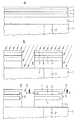
図1のaにはその表面に絶縁層1を有する支持装置が示されている。絶縁層1の下には例えばトランジスタのような半導体装置の他の素子が配設可能である。絶縁層1内には同一平面内に接触孔2が設けられており、この接触孔2は金属化材で充填されている。充填材としてはタングステン、タンタル、チタン、窒化チタン又はドープされたポリシリコンが用意される。nドープポリシリコンの場合その表面に金属製中間層が生じるようにこれをシリル化する必要がある。金属の導電材で満たされた接触孔2は形成すべき電極パターンの接続端子を形成する。支持装置の絶縁層1としては例えばBPSG(ホウ燐ケイ酸ガラス)のようなガラス層を備えていてもよく、このガラス層はガラスの流動化による平坦な表面が得られるという利点を供する。しかし例えばCMPのような化学研磨工程により平坦化された絶縁層を備えることも可能である。
【0021】
引続き絶縁層1及び接触孔2の表面上にこの例では高ドープp導電層であるベース層3が形成される。ドーピング濃度は後に使用されるエッチング溶液の選択により調整され、従ってエッチング率が極めて低くなるように選択されるべきである。例えばエチレンジアミン−ピロカテコール溶液には>1020cm-3のホウ素濃度を選択すると有利である。ベース層3の厚さは例えば300nmであってもよい。引続きベース層3の高ドープp導電層上にp-層及びp+層が交互する層列を施す。その際高ドープ層5及び7はベース層3の高ドープp導電層に相応してドープされる。低ドープp導電層4及び6は選択的に作用するエッチング剤に関して高いエッチング率を可能にするドーピング濃度を有する。例えば上述のエチレンジアミン−ピロカテコール溶液ではホウ素ドーピングは約1019cm-3又はそれ以下の濃度となる。
【0022】
層の厚さは低ドープp導電層が高ドープp導電層よりも厚くなるように選択される。例えばp-層4及び6は30nm、p+層5及び7は10nmの厚さである。
【0023】
層3〜7は同形に析出される。可能な析出方法は低圧での蒸気相からの化学析出、特に高温壁又は低温壁−LPCVD(液相蒸着法)又は分子線エピタキシーがある。層列は同じ反応容器内でその場で施されてもよい。更にp-ドープ層4及び6にはp+ドープポリシリコン層3、5及び7と比較して異なるプロセスパラメータを使用する必要がある。
【0024】
引続き図1のbには図示されていないマスクを形成し、それにより層列3〜7を異方性にエッチングし、1個又は複数個の開口8を形成する。エッチング剤としては水酸化カリウムが使用される。この図では開口8は支持装置の絶縁層1までエッチング除去されている。それにより切断された島が形成され、そこにそれぞれコンデンサを形成することができる。しかし必ずしも開口8をベース層3のp+導電層までエッチングする必要はない。ベース層3を完全にエッチング除去しない場合大表面のコンデンサ装置が形成される。ポリシリコン層列のパターン化は積層が平面図でみて丸形か角形になるように行われる(図4参照)。
【0025】
次の工程で開口8の縁領域内に層列3〜7を接続する高ドープp導電領域が形成される。それにはBF2イオンの斜方向注入が例えば垂直線に対し8°の角度で行われる。或はまた図1のb内に示されている開口の別の側面もホウ素イオンを注入することが可能である。この注入はホウ素イオンの射出下にある開口の縁領域内に低ドープp導電層4及び6の境界領域を高ドープする作用をし、その際ドーピング濃度は通常のp+ポリシリコン層のドーピングに相当する。引続き注入されたホウ素イオンの活性化を確実にするために熱処理工程が行われ、即ちポリシリコン層4又は6の相応する格子部分が覆われる。この場合高ドープ領域から低ドープ領域への拡散が行われないようにする必要がある。この熱処理工程はRTA(Rapid Thermal Annealing=迅速焼き戻し)法により行われると有利である。選択される温度は約850〜900℃である。
【0026】
図1のcは熱処理工程後生じたパターンを示すものである。開口8内にホウ素イオンを斜方向に注入することにより各開口の縁領域内にp+層3、5及び7を互いに接続するp+領域9が形成される。この実施例ではp+領域は左向きの“E”の形をしている。領域9に向き合う開口8の縁領域はそれに対して最初に形成された層列3〜7を保持し、従って低ドープ層4及び6は開口に対して露出している。
【0027】
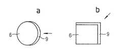
開口8を形成する異方性エッチング工程で平面図で丸形にパターン化された層列が形成されると、領域9は厚みを減らして積層の周囲の一定部分を覆う。長方形の積層の場合積層の一辺だけ又は積層の二辺の縁をp+ドープすることが可能となり、それにより領域9が積層の一辺だけに存在するか又は積層の二辺を角形に覆う。このように形成された積層の直径又は幅は約1μmである。図4のa、bは図1のcによりパターン化及びドープされた積層の実施例を示すものである。注入が行われた方向はそれぞれ矢印で示されている。図4に示された例では形成すべきコンデンサにとって極めて安定なパターンが生じる。
【0028】
次の工程でアルカリ性エッチング剤で装置を等方性に選択エッチングする。エッチング溶液としては例えばエチレンジアミン−ピロカテコール溶液が対象となる。選択ドーピングではアルカリ性エッチング溶液は低ドープp導電層が100:1〜1000:1の選択率でp+ドープ層よりも強くエッチングされるという特徴を有する。このエッチング工程後に図2のaのパターンが生じ、その際支柱パターンが生じるように上下に接続されているp+ドープ領域が僅かに残っている。このパターンは10と符号付けられている。
【0029】
図2のbによる次の工程でコンデンサ誘電体11が同形に析出される。この誘電体11は酸化ケイ素及び/又は窒化ケイ素から形成されてもよいが、第1の酸化ケイ素層、窒化ケイ素層及び第2の酸化ケイ素層からなるONO誘電体層からなると有利である。コンデンサ誘電体の層厚は合わせて約10nmに備えられている。しかし形成すべき高い容量に対してコンデンサ誘電体の厚さは薄く例えば3nmに選択可能である。
【0030】
コンデンサ誘電体11上に同形析出により例えばp+導電性ポリシリコンであるコンデンサの対向電極12を形成する(図2のc)。析出方法としては既に層列の形成に使用されてきたのと同様の方法が対象となる。
【0031】
対向電極12を半導体技術で一般的な方法で場合によってはパターン化及び接触化してもよい。
【0032】
図3はコンデンサの第2の実施例を示すものであるが、その際コンデンサはメモリコンデンサとしてDRAM半導体装置内に備えられている。その際支持装置は絶縁層1の下方に記憶容量用の選択トランジスタを含んでいる。基板20内にはフィールド酸化物領域21を用いて絶縁領域が形成されている。絶縁領域は共通のソース領域22を有する2つの選択トランジスタ30又は40を含んでいる。ソース領域22の両側にチャネル領域が延びており、このチャネル領域は断面が全面的に絶縁されているワード線としてのゲート32又は42により制御される。フィールド酸化物21に向かってこれらのトランジスタはそれぞれドレイン領域31又は41を有する。選択トランジスタ及びコンデンサからなるメモリセルの各ドレイン領域は絶縁層1内の接触孔2を介してコンデンサの電極パターンと接続されている。例えばトランジスタ30のドレイン31は第1のコンデンサK1の電極パターン33とまたトランジスタ40のドレイン41はコンデンサK2の電極パターン43と接続されている。電極パターン33又は43は図1及び図2の実施例とは異なり、支持層の絶縁層1内の接触孔2をまず自己整合された重複接触部として各トランジスタのドレイン領域に対して形成し、その後接触孔2を充填するp+ドープベース層を同形析出により形成するようにして形成される。図3の実施例ではソース領域22、ドレイン領域31及び41はp+ドープ領域としてpチャネル選択トランジスタに相応して設けられている。nチャネル選択トランジスタの場合には接触孔2は例えばタングステン、タンタル、チタン、窒化チタン又はケイ化物のような金属の導電材料からなる中間層を有していなければならない。フィールド酸化物領域21の上方には隣接するメモリセル用のワード線23が配設されている。ワード線23、32及び42は高ドープポリシリコン又はポリサイドからなると有利である。ソース領域22は自己整合された重複する接触部によりタングステン又はポリサイドからなるビット線50と接触化されている。図3の記憶装置内の全てのコンデンサはいわゆるセル板の形の共有の対向電極34を有している。
【0033】
図5はいわゆる深鍋形装置として形成されているコンデンサのもう1つの実施例を示すものである。例えば金属を充填された接触孔2を有する支持層の絶縁層1上にまず絶縁層60を形成し、この層を引続きパターン化し、絶縁層1又は充填された接触孔2上にまで達する開口70を形成する。同形析出により上記の方法でまず高ドープp導電ポリシリコンからなるベース層61及びそれに引続いて低ドープ及び高ドープp導電層が交互する層列を施す。低ドープ層を62、64及び66と符号付けし、一方高ドープ層を63及び65と符号付ける。まず層61〜66の深鍋形に入り組んでいるパターンが形成され、その際後から施された層は最初に施された層よりも小さい底面及び縁寸法を有する。マスク法及び引続いての異方性エッチング工程により層列の中心にベース層61上にまで達する開口70を形成する。従って底面領域内の層列は露出している(図5のa参照)。
【0034】
その後この開口70を高ドープp導電材料で少なくとも部分的に充填する。これは層63及び65の場合に相応して実施可能である。或は層の縁の高さに比べて開口が十分大きい場合斜方向イオン注入が選択される。或はまた開口の形成及びこの開口をp+材料で満たすには、マスク及びその後の一又は複数の注入工程によりマスク開口を通して規定された層列の底部の範囲にp+原子をドーピングする。複数の注入工程を最大ドーピング濃度がそれぞれp-層領域内にあるようにすると有利である。底部範囲にはマスクの開口により一定のp+支柱が生じる。
【0035】
p+ドープ領域63、65は少なくとも1020cm-3のドーピング濃度を有し、一方低ドープp-領域62、64及び66はせいぜい1019cm-3のドーピング濃度を有する。引続きp+ドープ層からの拡散が行われないように熱処理工程例えばRTA工程を実施する。引続きパターンをアルカリエッチング溶液中で選択的に等方性エッチングする。その際p+ドープ層はそのまま残留し、一方p-ドープ層はエッチング除去される。その際エッチング処理の選択率は十分高く、従って図5のbの燭台の形と類似する支持パターンが生じる。図1及び図2の実施例とは異なり中央の高ドープp導電領域71は層列の底面部分内で開口70が完全に満たされるように形成される。この析出には既に説明した同形析出により行い、これに続いてパターン化が行われる。従って領域71は図5のaに見られる層列61〜66をその底面領域内で接続する。
【0036】
図5のcに基づき引続き例えばONO誘電体としての誘電体73及び例えばp+ドープポリシリコンからなる対向電極74を同形析出により形成する。誘電体73及び対向電極74は引続きパターン化可能である。
【0037】
図3の実施例において所望の場合には同形析出によりベース層を接触孔2内にも析出してもよい。更に図5に示されている形式のコンデンサをシリコン基板内に配設し、電極パターンをトレンチの縁に例えばDRAM装置の選択トランジスタのような半導体装置と接続することも可能である。この場合対向電極74は公知のトレンチコンデンサの場合のように連続するセル板として形成してもよい。このコンデンサがシリコン基板内にトレンチコンデンサとして配設されている場合p基板にベース領域をトレンチ領域の高ドーピングにより形成するのに十分である。nドープ基板内においては、ベース層61の高ドープp導電層を絶縁層により基板と絶縁するようにする。この種の層は酸化ケイ素及び/又は窒化ケイ素からなっていてもよい。
【図面の簡単な説明】
【図1】a〜cは本発明による半導体装置におけるコンデンサの第1の実施例の各工程の断面図。
【図2】a〜cは第1の実施例の図1の工程に引続き行われる工程の断面図。
【図3】本発明による半導体装置におけるコンデンサの第2の実施例の概略断面図。
【図4】図1のc工程でパターン化された積層コンデンサのaは丸形の概略平面図、bは角形の概略平面図。
【図5】a〜cは本発明による半導体装置におけるコンデンサの第3の実施例の工程の断面図。
【符号の説明】
1 絶縁層
2、接触孔
3、61 ベース層
4、6、62、64、66 低ドープ領域
5、7、63、65 高ドープ領域
8、70 開口
9 接続パターン(p+領域)
10、33、43 電極パターン
11、73 コンデンサ誘電体
12、34、74 対向電極(p+ドープポリシリコン)
20 基板
30、40 選択トランジスタ
21 フィールド酸化物領域(絶縁領域)
22 ソース領域
23、32、42 ワード線
31、41 ドレイン領域
71 支柱素子
K1 第1コンデンサ
K2 第2コンデンサ[0001]
BACKGROUND OF THE INVENTION
The present invention relates to a semiconductor device having an electrode pattern including a plurality of elements that are electrically connected in the vertical direction by a connection pattern and spaced apart from each other, a capacitor dielectric, and a counter electrode, particularly a capacitor in a DRAM memory device. About. The present invention further relates to a method of manufacturing a capacitor in a semiconductor device.
[0002]
[Prior art]
Many integrated circuits require capacitors. Besides typical examples of dynamic memory cells, analog-to-digital converters or digital-to-analog converters and filter circuits are conceivable. In particular, since the integration density must be increased or the chip surface must be saved, measures for reducing the large required area of the capacitor are required for pattern miniaturization. In this case, a typical example is a dynamic semiconductor memory device, and the area required for a one-transistor memory cell normally used at that time is reduced as the memory density increases from the memory generation to the memory generation. At the same time, the minimum capacity of the storage capacitor must be maintained.
[0003]
In the case of a dynamic semiconductor memory device, a one-transistor memory cell includes one read transistor and one capacitor. By manipulating the read transistor via the word line, the information stored in the capacitor, i.e. the charge, is read via the bit line. The storage capacitor must have a minimum capacity for reliable accumulation of charge and simultaneous identification of the read information. Conventionally, the lower limit for the capacity of the storage capacitor is 20 fF. To achieve this capacitor capacity, the dielectric thickness must be as thin as possible and the capacitor area as large as possible.
[0004]
Both the read transistor and the capacitor have been formed as a planar device up to the memory generation of 1 Mbit, but a device in which the capacitor is arranged in a trench (trench capacitor) is known from the memory generation up to 4 Mbit. The capacitor electrode is disposed along the surface of the trench. Overall, the effective area of the capacitor is enlarged compared to the planar arrangement on the surface of the substrate.
[0005]
Another possibility to increase the capacitance of the capacitor if the required area of the capacitor is left as it is or reduced is to form the capacitor as a multilayer capacitor. At this time, a pattern made of polysilicon, for example, a coronal pattern or a cylindrical pattern, is formed above the word line and brought into contact with the substrate. This polysilicon pattern forms a node of the memory provided with a capacitor dielectric and a capacitor plate, a so-called cell plate. This concept has the advantage of being compatible with logical processes.
[0006]
For the capacitor, free space above the substrate surface can be used. At this time, as long as adjacent memory cell patterns are separated from each other, all the cell surfaces can be covered with the polysilicon pattern. In this regard, fin-type multilayer capacitors and crown-type multilayer capacitors are known.
[0007]
EP 0 415 530 discloses a semiconductor memory device having a multilayer capacitor as a storage capacitor. The multilayer capacitor includes a polysilicon pattern having a plurality of polysilicon layers that are arranged substantially in parallel and vertically and are connected to each other via at least side columns. The lateral struts are formed by a polysilicon layer, which is then reverse etched to leave a substantially vertically disposed web connecting the polysilicon layers disposed above and below. . The pattern is formed by alternately depositing a polysilicon layer and a silicon oxide layer that can be selectively etched with respect to the surface of the substrate, and patterning these layers to form side posts on at least the side of the pattern, thereby oxidizing the layer. It is formed by selectively etching away the silicon layer. The polysilicon pattern is then doped with arsenic. Subsequently, silicon oxide is formed as a capacitor dielectric by thermal oxidation, and a cell plate made of doped polysilicon is deposited thereon.
[0008]
U.S. Pat. No. 5,240,871 discloses a capacitor having electrode layers stacked one above the other, in which an insulating layer, which can be etched variously quickly, is applied on a polysilicon layer, and these layers are subsequently used as pillars. Patterning and etching are performed so as to generate a skeleton. The doped polysilicon is then followed by the deposition of a silicon nitride layer, followed by cell plate formation.
[0009]
[Problems to be solved by the invention]
An object of the present invention is to provide a capacitor in a semiconductor memory device that can reduce the cost of a process and a required area and can achieve a high packaging density. Furthermore, it is providing the manufacturing method of such a capacitor | condenser.
[0010]
[Means for Solving the Problems]
These problems are solved by the capacitor having the features of
[0011]
An important advantage of the present invention is that in this device the thickness when the capacitor is laid down or the width when the capacitor is raised is less than with known capacitors. Since a capacitor having a required minimum cell capacity of 20 fF is required to have a small thickness and a small area, the capacitor according to the present invention can be used particularly in a DRAM semiconductor device. It is considered that this type of capacitor can also realize the memory capacity of the future DRAM generation, which will impose even stricter requirements on the required area. To do so, it is only necessary to increase the number of layers when the area of one layer is reduced. In addition, the capacitor thickness or width can be reduced by reducing the layer thickness and the dielectric thickness. Furthermore, the capacitor according to the present invention has the advantage that the electrode pattern of a p-channel transistor can be directly connected to the drain of the transistor through a contact hole. However, other ways of bringing the electrode pattern into contact with other circuit elements are also possible. For example, in the case of an n-channel selection transistor, the contact between the electrode pattern and the drain of the transistor can be performed via a metal intermediate layer or silicon layer made of, for example, tantalum, titanium, titanium nitride, or a contact hole filler (for example, tungsten). .
[0012]
The method according to the present invention has the important advantage that it requires fewer processing steps than the known methods, and does not require the loss from other viewpoints associated therewith.
[0013]
The capacitor in the semiconductor device is formed so as to have an electrode pattern including a plurality of elements that are arranged at intervals and are electrically connected to each other by a connection pattern. The above connection pattern is made of a p-conductive material having a doping concentration of 1020 cm−3 or more as a whole. In this case, the elements of this electrode pattern can be arranged in a plan view in the vertical direction or in parallel. The connection pattern extends in a direction perpendicular to the surface of the element at at least one edge. In addition, the electrode pattern elements are formed in a deep-bowl shape and are intertwined with each other. In this case, the connection pattern is connected to the bottom of the capacitor device and one bottom surface portion or a plurality of bottom surface portions within the range of the deep-bowl shape. Has been. It is advantageous if the connection pattern can be formed as a rod-shaped post element in the center of the deep pan-shaped electrode pattern.
[0014]
In the method of manufacturing a capacitor according to the present invention, a base layer including a p+ layer is first formed on the surface of a supporting device, and a layer sequence in which a lightly doped p conductive layer and a highly doped p conductive layer are alternately formed is applied thereon. The layer sequence is then anisotropically etched so that an opening is formed that reaches at least the p+ layer of the base layer. Thereafter, a p+ conductive region connecting the layer sequence is formed at least in the edge region of the opening. Subsequently, the lightly doped p-conducting layer of the layer sequence is selectively etched with respect to the p+ layer, and a dielectric is deposited to form a counter electrode.
[0015]
The base layer can then be formed so as to include only the p+ layer or include a p+ layer with an underlying oxide and / or nitride layer. Depending on the desired pattern of the capacitor, the p+ region in the opening is formed by oblique ion (boron ion) implantation or by deposition of a p+ conductive material. What is important here is that this layer sequence is not completely covered by the p+ region so that the etching action can be limited to a lightly doped p material for subsequent selective etching.
[0016]
The selective etching is performed with an alkaline etching agent such as an ethylenediamine-pyrocatechol solution or a potassium hydroxide solution. After selective etching of the material of the lightly doped p-conducting layer, a dielectric, such as an ONO dielectric, is applied, followed by isomorphous deposition with the conductive material as the counter electrode.
[0017]
A base layer can be formed on the planarized surface of the insulator. As long as a contact hole is provided in the insulator for the underlying connection surface, this contact hole can likewise be filled with the p+ material of the base layer. In addition to this vertical contact of the electrode pattern, it is also possible to make contact via a lateral connection. The base layer and the subsequent electrode pattern can be formed in the trench of the insulating layer or the silicon layer. In some cases, a silicon oxide layer and / or a silicon nitride layer is provided under the p+ partial layer of the base layer.
[0018]
The production of the capacitor according to the invention is based on the recognition that the etching rate of p+ doped silicon is very low in alkaline etching solutions compared to low doped silicon. A publication by H. Seidel et al., “Anisotropic Etching of Crystalline in Alkaline Solutions” (J. Electrochem. Soc. Vol. 137, No. 11, 1990). According to November, pages 3626-3632), the etching rate of p-doped silicon is constant up to a concentration of 1019 cm-3 in an ethylenediamine-pyrocatechol solution, but then drops drastically. At a concentration of 2 · 1020 cm−3 , the etching rate is only 1/1000 lower than that at 1019 cm−3 .
[0019]
【Example】
The present invention will be described in detail below based on the drawings and examples.
[0020]
FIG. 1a shows a support device having an insulating
[0021]
Subsequently, a
[0022]
The layer thickness is selected such that the lightly doped p-conductive layer is thicker than the highly doped p-conductive layer. For example, p− layers 4 and 6 are 30 nm thick, and p+ layers 5 and 7 are 10 nm thick.
[0023]
Layers 3-7 are deposited in the same shape. Possible deposition methods are chemical deposition from the vapor phase at low pressure, in particular hot or cold wall-LPCVD (liquid phase deposition) or molecular beam epitaxy. The layer sequence may be applied in situ within the same reaction vessel. Furthermore, it is necessary to use different process parameters for the p− doped
[0024]
Subsequently, a mask not shown in FIG. 1 b is formed, whereby the
[0025]
In the next step, a highly doped p-conducting region connecting the
[0026]
FIG. 1c shows a pattern generated after the heat treatment step. P+ region 9 connected to each other p+ layers 3, 5 and 7 in the edge region of the opening by implanting boron ions into the
[0027]
When a layer sequence patterned in a circular shape in plan view is formed in the anisotropic etching process for forming the
[0028]
In the next step, the apparatus is selectively etched isotropically with an alkaline etchant. For example, an ethylenediamine-pyrocatechol solution is an etching solution. In selective doping, the alkaline etching solution is characterized in that the lightly doped p conductive layer is etched more strongly than the p+ doped layer with a selectivity of 100: 1 to 1000: 1. After this etching step, the pattern of FIG. 2a is produced, and a fewp.sup. + Doped regions connected up and down remain so that a support pattern is formed. This pattern is labeled 10.
[0029]
In the next step according to FIG. 2b, the
[0030]
On the
[0031]
The
[0032]
FIG. 3 shows a second embodiment of the capacitor. In this case, the capacitor is provided as a memory capacitor in the DRAM semiconductor device. In this case, the supporting device includes a selection transistor for storage capacity below the insulating
[0033]
FIG. 5 shows another embodiment of a capacitor formed as a so-called deep pot type device. For example, an insulating
[0034]
This
[0035]
The p+ doped
[0036]
Based on FIG. 5c, a dielectric 73 as an ONO dielectric, for example, and a
[0037]
In the embodiment of FIG. 3, the base layer may also be deposited in the
[Brief description of the drawings]
1A to 1C are cross-sectional views of respective steps of a first embodiment of a capacitor in a semiconductor device according to the present invention.
FIGS. 2a to 2c are cross-sectional views of processes performed subsequent to the process of FIG. 1 of the first embodiment.
FIG. 3 is a schematic cross-sectional view of a second embodiment of a capacitor in a semiconductor device according to the present invention.
4A is a schematic plan view of a round shape of the multilayer capacitor patterned in step c of FIG. 1, and FIG. 4B is a schematic plan view of a square shape.
FIGS. 5a to 5c are cross-sectional views of steps of a third embodiment of the capacitor in the semiconductor device according to the present invention. FIGS.
[Explanation of symbols]
1 Insulating
10, 33, 43
20
22
Claims (13)
Translated fromJapanese支持装置の表面上に高ドープされたp導電層(3、61)を含むベース層を形成し、
高ドープp導電層(3、61)の表面上に交互に低ドープp導電層と高ドープp導電層とからなる層列(4〜7、62〜66)を施し、
この層列を異方性エッチングにより少なくともベース層(3、61)にまで達する開口(8、70)の形成下にパターン化し、
低ドープp導電層及び高ドープp導電層からなる層列への斜方向イオン注入により開口(8)内に高ドープp導電領域(9、71)を形成し、
層列の低ドープp導電層を高ドープp導電層に対して選択的にエッチングし、
コンデンサ誘電体(11)を同形に析出し、しかる後
コンデンサ誘電体(11)上に導電層(12)を同形に析出する。A method comprising the following steps for manufacturing a capacitor in a semiconductor device.
Forming a base layer comprising a highly doped p-conducting layer (3, 61) on the surface of the support device;
A layer sequence (4-7, 62-66) consisting of a lightly doped p conductive layer and a highly doped p conductive layer is alternately applied on the surface of the highly doped p conductive layer (3, 61),
This layer sequence is patterned by anisotropic etching under the formation of openings (8, 70) reaching at least the base layer (3, 61),
A highly doped p-conducting region (9, 71) is formed in the opening (8) by oblique ion implantation into a layer sequence comprising a low-doped p-conducting layer and a highly-doped p-conducting layer;
Etching the lightly doped p-conductive layer of the layer sequence selectively with respect to the highly doped p-conductive layer;
Capacitor dielectric (11) is deposited in the same shape, then
A conductive layer (12) is deposited in the same shape on the capacitor dielectric (11) .
Applications Claiming Priority (2)
| Application Number | Priority Date | Filing Date | Title |
|---|---|---|---|
| DE19527023ADE19527023C1 (en) | 1995-07-24 | 1995-07-24 | Method of manufacturing a capacitor in a semiconductor device |
| DE19527023.1 | 1995-07-24 |
Publications (2)
| Publication Number | Publication Date |
|---|---|
| JPH0936333A JPH0936333A (en) | 1997-02-07 |
| JP3955344B2true JP3955344B2 (en) | 2007-08-08 |
Family
ID=7767656
Family Applications (1)
| Application Number | Title | Priority Date | Filing Date |
|---|---|---|---|
| JP21217296AExpired - Fee RelatedJP3955344B2 (en) | 1995-07-24 | 1996-07-24 | Manufacturing method of capacitor in semiconductor device |
Country Status (7)
| Country | Link |
|---|---|
| US (1) | US5989972A (en) |
| EP (1) | EP0756326B1 (en) |
| JP (1) | JP3955344B2 (en) |
| KR (1) | KR100425399B1 (en) |
| DE (2) | DE19527023C1 (en) |
| SG (1) | SG43381A1 (en) |
| TW (1) | TW315507B (en) |
Families Citing this family (15)
| Publication number | Priority date | Publication date | Assignee | Title |
|---|---|---|---|---|
| JPH11297960A (en)* | 1998-04-16 | 1999-10-29 | Mitsubishi Electric Corp | Semiconductor device and manufacturing method thereof |
| US5744833A (en)* | 1996-08-16 | 1998-04-28 | United Microelectronics Corporation | Semiconductor memory device having tree-type capacitor |
| US6309975B1 (en)* | 1997-03-14 | 2001-10-30 | Micron Technology, Inc. | Methods of making implanted structures |
| DE19842704C2 (en)* | 1998-09-17 | 2002-03-28 | Infineon Technologies Ag | Manufacturing process for a capacitor with a high epsilon dielectric or a ferroelectric according to the fin stack principle using a negative mold |
| DE19842684C1 (en)* | 1998-09-17 | 1999-11-04 | Siemens Ag | Integrated circuit high-permittivity capacitor arranged on support structure in semiconductor arrangement e.g. for DRAM circuit or ADC |
| DE19842682A1 (en)* | 1998-09-17 | 2000-04-06 | Siemens Ag | Capacitor with a high-e dielectric or a ferro-electrical according to the fin stack principle and manufacturing process |
| US6426253B1 (en)* | 2000-05-23 | 2002-07-30 | Infineon Technologies A G | Method of forming a vertically oriented device in an integrated circuit |
| US6339241B1 (en)* | 2000-06-23 | 2002-01-15 | International Business Machines Corporation | Structure and process for 6F2 trench capacitor DRAM cell with vertical MOSFET and 3F bitline pitch |
| US6573137B1 (en) | 2000-06-23 | 2003-06-03 | International Business Machines Corporation | Single sided buried strap |
| DE10038728A1 (en)* | 2000-07-31 | 2002-02-21 | Infineon Technologies Ag | Semiconductor memory cell arrangement and method for the production thereof |
| US6368970B1 (en)* | 2000-08-24 | 2002-04-09 | Infineon Technologies Ag | Semiconductor configuration and corresponding production process |
| FR2819633B1 (en) | 2001-01-18 | 2003-05-30 | St Microelectronics Sa | METHOD FOR INTEGRATING A DRAM MEMORY |
| US7482675B2 (en)* | 2005-06-24 | 2009-01-27 | International Business Machines Corporation | Probing pads in kerf area for wafer testing |
| TWI306303B (en)* | 2006-08-23 | 2009-02-11 | Promos Technologies Inc | Method for preparing memory structure |
| EP2683995B1 (en)* | 2011-03-09 | 2015-04-22 | Danfoss A/S | An expansion valve for a vapour compression system with reversible fluid flow |
Family Cites Families (17)
| Publication number | Priority date | Publication date | Assignee | Title |
|---|---|---|---|---|
| DE3856143T2 (en)* | 1987-06-17 | 1998-10-29 | Fujitsu Ltd | Method of making a dynamic random access memory cell |
| JPH0338061A (en)* | 1989-07-05 | 1991-02-19 | Fujitsu Ltd | Semiconductor memory |
| US5160987A (en)* | 1989-10-26 | 1992-11-03 | International Business Machines Corporation | Three-dimensional semiconductor structures formed from planar layers |
| KR960016837B1 (en)* | 1990-10-29 | 1996-12-21 | Nec Kk | Semiconductor memory device and manufacturing method thereof |
| US5126280A (en)* | 1991-02-08 | 1992-06-30 | Micron Technology, Inc. | Stacked multi-poly spacers with double cell plate capacitor |
| JP3158462B2 (en)* | 1991-03-11 | 2001-04-23 | 松下電器産業株式会社 | Semiconductor memory device and method of manufacturing the same |
| JPH05183121A (en)* | 1991-04-01 | 1993-07-23 | Fujitsu Ltd | Semiconductor device and manufacturing method thereof |
| JP2797746B2 (en)* | 1991-04-05 | 1998-09-17 | 日本電気株式会社 | Method of manufacturing capacitive element for integrated circuit |
| US5084405A (en)* | 1991-06-07 | 1992-01-28 | Micron Technology, Inc. | Process to fabricate a double ring stacked cell structure |
| US5240871A (en)* | 1991-09-06 | 1993-08-31 | Micron Technology, Inc. | Corrugated storage contact capacitor and method for forming a corrugated storage contact capacitor |
| US5155657A (en)* | 1991-10-31 | 1992-10-13 | International Business Machines Corporation | High area capacitor formation using material dependent etching |
| US5153813A (en)* | 1991-10-31 | 1992-10-06 | International Business Machines Corporation | High area capacitor formation using dry etching |
| US5150276A (en)* | 1992-01-24 | 1992-09-22 | Micron Technology, Inc. | Method of fabricating a vertical parallel cell capacitor having a storage node capacitor plate comprising a center fin effecting electrical communication between itself and parallel annular rings |
| JP2802470B2 (en)* | 1992-03-12 | 1998-09-24 | 三菱電機株式会社 | Semiconductor device and manufacturing method thereof |
| DE4307575C2 (en)* | 1992-03-12 | 1996-07-11 | Mitsubishi Electric Corp | Semiconductor device and manufacturing method therefor |
| JPH069154A (en)* | 1992-04-23 | 1994-01-18 | Teijin Seiki Co Ltd | Thread switching winder |
| KR0120547B1 (en)* | 1993-12-29 | 1997-10-27 | 김주용 | Fabricating method of capacitor |
- 1995
- 1995-07-24DEDE19527023Apatent/DE19527023C1/ennot_activeExpired - Fee Related
- 1996
- 1996-07-02TWTW085107986Apatent/TW315507B/zhactive
- 1996-07-04SGSG1996010212Apatent/SG43381A1/enunknown
- 1996-07-18DEDE59608481Tpatent/DE59608481D1/ennot_activeExpired - Fee Related
- 1996-07-18EPEP96111674Apatent/EP0756326B1/ennot_activeExpired - Lifetime
- 1996-07-24JPJP21217296Apatent/JP3955344B2/ennot_activeExpired - Fee Related
- 1996-07-24USUS08/685,847patent/US5989972A/ennot_activeExpired - Lifetime
- 1996-07-24KRKR1019960029913Apatent/KR100425399B1/ennot_activeExpired - Fee Related
Also Published As
| Publication number | Publication date |
|---|---|
| DE59608481D1 (en) | 2002-01-31 |
| DE19527023C1 (en) | 1997-02-27 |
| KR100425399B1 (en) | 2004-06-26 |
| SG43381A1 (en) | 1997-10-17 |
| EP0756326B1 (en) | 2001-12-19 |
| TW315507B (en) | 1997-09-11 |
| EP0756326A1 (en) | 1997-01-29 |
| JPH0936333A (en) | 1997-02-07 |
| US5989972A (en) | 1999-11-23 |
Similar Documents
| Publication | Publication Date | Title |
|---|---|---|
| US7667258B2 (en) | Double-sided container capacitors using a sacrificial layer | |
| US7582925B2 (en) | Integrated circuit devices including insulating support layers | |
| JP2826036B2 (en) | Method of manufacturing a uniform and repeatable conductive container structure or DRAM container storage capacitor | |
| JP3955344B2 (en) | Manufacturing method of capacitor in semiconductor device | |
| US5005103A (en) | Method of manufacturing folded capacitors in semiconductor and folded capacitors fabricated thereby | |
| JPH0821693B2 (en) | Method for manufacturing highly integrated semiconductor memory device | |
| JPH0426156A (en) | Manufacture of semiconductor device | |
| US7214582B2 (en) | Semiconductor substrate and semiconductor circuit formed therein and fabrication methods | |
| JPH10144883A (en) | Semiconductor memory device and method of manufacturing the same | |
| KR100341654B1 (en) | Semiconductor memory device and manufacturing method thereof | |
| US5789290A (en) | Polysilicon CMP process for high-density DRAM cell structures | |
| JP2672936B2 (en) | Method of manufacturing semiconductor memory cell, as well as method of manufacturing capacitor of semiconductor memory cell | |
| JP2000049301A (en) | Semiconductor storage device | |
| US5976977A (en) | Process for DRAM capacitor formation | |
| CN1171285C (en) | Semiconductor structure and manufacturing method thereof, memory cell array and manufacturing method thereof | |
| GB2321778A (en) | Stacked capacitor | |
| KR100273706B1 (en) | Method for manufacturing semiconductor device | |
| JPH11177052A (en) | Semiconductor device and manufacturing method thereof | |
| GB2321775A (en) | Method for fabricating a capacitor structure for a semiconductor memory device | |
| KR100292693B1 (en) | Capacitor and Manufacturing Method | |
| KR100313084B1 (en) | Method for manufacturing a semiconductor device | |
| GB2322964A (en) | Capacitors for DRAM cells | |
| JP2000031413A (en) | Semiconductor device and its manufacture | |
| KR0132837B1 (en) | Capacitor of semiconductor device having storage electrode composed of conductive layers with different concentration of dopant and manufacturing method thereof | |
| KR930004724B1 (en) | Manufacturing method of multilayers stack capacitor and capacitor fabricated thereby |
Legal Events
| Date | Code | Title | Description |
|---|---|---|---|
| A977 | Report on retrieval | Free format text:JAPANESE INTERMEDIATE CODE: A971007 Effective date:20051130 | |
| A131 | Notification of reasons for refusal | Free format text:JAPANESE INTERMEDIATE CODE: A131 Effective date:20061130 | |
| A521 | Request for written amendment filed | Free format text:JAPANESE INTERMEDIATE CODE: A523 Effective date:20070223 | |
| TRDD | Decision of grant or rejection written | ||
| A01 | Written decision to grant a patent or to grant a registration (utility model) | Free format text:JAPANESE INTERMEDIATE CODE: A01 Effective date:20070405 | |
| A61 | First payment of annual fees (during grant procedure) | Free format text:JAPANESE INTERMEDIATE CODE: A61 Effective date:20070502 | |
| R150 | Certificate of patent or registration of utility model | Free format text:JAPANESE INTERMEDIATE CODE: R150 | |
| FPAY | Renewal fee payment (event date is renewal date of database) | Free format text:PAYMENT UNTIL: 20110511 Year of fee payment:4 | |
| FPAY | Renewal fee payment (event date is renewal date of database) | Free format text:PAYMENT UNTIL: 20120511 Year of fee payment:5 | |
| FPAY | Renewal fee payment (event date is renewal date of database) | Free format text:PAYMENT UNTIL: 20130511 Year of fee payment:6 | |
| LAPS | Cancellation because of no payment of annual fees |