JP3952509B2 - Image encoding apparatus, image encoding method, and medium storing image encoding program - Google Patents
Image encoding apparatus, image encoding method, and medium storing image encoding programDownload PDFInfo
- Publication number
- JP3952509B2 JP3952509B2JP53694297AJP53694297AJP3952509B2JP 3952509 B2JP3952509 B2JP 3952509B2JP 53694297 AJP53694297 AJP 53694297AJP 53694297 AJP53694297 AJP 53694297AJP 3952509 B2JP3952509 B2JP 3952509B2
- Authority
- JP
- Japan
- Prior art keywords
- picture
- encoding
- threshold value
- image
- data
- Prior art date
- Legal status (The legal status is an assumption and is not a legal conclusion. Google has not performed a legal analysis and makes no representation as to the accuracy of the status listed.)
- Expired - Fee Related
Links
Images


Classifications
- H—ELECTRICITY
- H04—ELECTRIC COMMUNICATION TECHNIQUE
- H04N—PICTORIAL COMMUNICATION, e.g. TELEVISION
- H04N21/00—Selective content distribution, e.g. interactive television or video on demand [VOD]
- H04N21/40—Client devices specifically adapted for the reception of or interaction with content, e.g. set-top-box [STB]; Operations thereof
- H04N21/43—Processing of content or additional data, e.g. demultiplexing additional data from a digital video stream; Elementary client operations, e.g. monitoring of home network or synchronising decoder's clock; Client middleware
- H04N21/44—Processing of video elementary streams, e.g. splicing a video clip retrieved from local storage with an incoming video stream or rendering scenes according to encoded video stream scene graphs
- H04N21/44004—Processing of video elementary streams, e.g. splicing a video clip retrieved from local storage with an incoming video stream or rendering scenes according to encoded video stream scene graphs involving video buffer management, e.g. video decoder buffer or video display buffer
- H—ELECTRICITY
- H04—ELECTRIC COMMUNICATION TECHNIQUE
- H04N—PICTORIAL COMMUNICATION, e.g. TELEVISION
- H04N19/00—Methods or arrangements for coding, decoding, compressing or decompressing digital video signals
- H04N19/50—Methods or arrangements for coding, decoding, compressing or decompressing digital video signals using predictive coding
- H04N19/503—Methods or arrangements for coding, decoding, compressing or decompressing digital video signals using predictive coding involving temporal prediction
- H04N19/51—Motion estimation or motion compensation
- H—ELECTRICITY
- H04—ELECTRIC COMMUNICATION TECHNIQUE
- H04N—PICTORIAL COMMUNICATION, e.g. TELEVISION
- H04N19/00—Methods or arrangements for coding, decoding, compressing or decompressing digital video signals
- H04N19/10—Methods or arrangements for coding, decoding, compressing or decompressing digital video signals using adaptive coding
- H04N19/102—Methods or arrangements for coding, decoding, compressing or decompressing digital video signals using adaptive coding characterised by the element, parameter or selection affected or controlled by the adaptive coding
- H04N19/124—Quantisation
- H—ELECTRICITY
- H04—ELECTRIC COMMUNICATION TECHNIQUE
- H04N—PICTORIAL COMMUNICATION, e.g. TELEVISION
- H04N19/00—Methods or arrangements for coding, decoding, compressing or decompressing digital video signals
- H04N19/10—Methods or arrangements for coding, decoding, compressing or decompressing digital video signals using adaptive coding
- H04N19/102—Methods or arrangements for coding, decoding, compressing or decompressing digital video signals using adaptive coding characterised by the element, parameter or selection affected or controlled by the adaptive coding
- H04N19/132—Sampling, masking or truncation of coding units, e.g. adaptive resampling, frame skipping, frame interpolation or high-frequency transform coefficient masking
- H—ELECTRICITY
- H04—ELECTRIC COMMUNICATION TECHNIQUE
- H04N—PICTORIAL COMMUNICATION, e.g. TELEVISION
- H04N19/00—Methods or arrangements for coding, decoding, compressing or decompressing digital video signals
- H04N19/10—Methods or arrangements for coding, decoding, compressing or decompressing digital video signals using adaptive coding
- H04N19/134—Methods or arrangements for coding, decoding, compressing or decompressing digital video signals using adaptive coding characterised by the element, parameter or criterion affecting or controlling the adaptive coding
- H04N19/136—Incoming video signal characteristics or properties
- H04N19/14—Coding unit complexity, e.g. amount of activity or edge presence estimation
- H—ELECTRICITY
- H04—ELECTRIC COMMUNICATION TECHNIQUE
- H04N—PICTORIAL COMMUNICATION, e.g. TELEVISION
- H04N19/00—Methods or arrangements for coding, decoding, compressing or decompressing digital video signals
- H04N19/10—Methods or arrangements for coding, decoding, compressing or decompressing digital video signals using adaptive coding
- H04N19/134—Methods or arrangements for coding, decoding, compressing or decompressing digital video signals using adaptive coding characterised by the element, parameter or criterion affecting or controlling the adaptive coding
- H04N19/146—Data rate or code amount at the encoder output
- H04N19/152—Data rate or code amount at the encoder output by measuring the fullness of the transmission buffer
- H—ELECTRICITY
- H04—ELECTRIC COMMUNICATION TECHNIQUE
- H04N—PICTORIAL COMMUNICATION, e.g. TELEVISION
- H04N19/00—Methods or arrangements for coding, decoding, compressing or decompressing digital video signals
- H04N19/10—Methods or arrangements for coding, decoding, compressing or decompressing digital video signals using adaptive coding
- H04N19/134—Methods or arrangements for coding, decoding, compressing or decompressing digital video signals using adaptive coding characterised by the element, parameter or criterion affecting or controlling the adaptive coding
- H04N19/157—Assigned coding mode, i.e. the coding mode being predefined or preselected to be further used for selection of another element or parameter
- H04N19/159—Prediction type, e.g. intra-frame, inter-frame or bidirectional frame prediction
- H—ELECTRICITY
- H04—ELECTRIC COMMUNICATION TECHNIQUE
- H04N—PICTORIAL COMMUNICATION, e.g. TELEVISION
- H04N19/00—Methods or arrangements for coding, decoding, compressing or decompressing digital video signals
- H04N19/10—Methods or arrangements for coding, decoding, compressing or decompressing digital video signals using adaptive coding
- H04N19/134—Methods or arrangements for coding, decoding, compressing or decompressing digital video signals using adaptive coding characterised by the element, parameter or criterion affecting or controlling the adaptive coding
- H04N19/164—Feedback from the receiver or from the transmission channel
- H—ELECTRICITY
- H04—ELECTRIC COMMUNICATION TECHNIQUE
- H04N—PICTORIAL COMMUNICATION, e.g. TELEVISION
- H04N19/00—Methods or arrangements for coding, decoding, compressing or decompressing digital video signals
- H04N19/10—Methods or arrangements for coding, decoding, compressing or decompressing digital video signals using adaptive coding
- H04N19/169—Methods or arrangements for coding, decoding, compressing or decompressing digital video signals using adaptive coding characterised by the coding unit, i.e. the structural portion or semantic portion of the video signal being the object or the subject of the adaptive coding
- H04N19/17—Methods or arrangements for coding, decoding, compressing or decompressing digital video signals using adaptive coding characterised by the coding unit, i.e. the structural portion or semantic portion of the video signal being the object or the subject of the adaptive coding the unit being an image region, e.g. an object
- H04N19/172—Methods or arrangements for coding, decoding, compressing or decompressing digital video signals using adaptive coding characterised by the coding unit, i.e. the structural portion or semantic portion of the video signal being the object or the subject of the adaptive coding the unit being an image region, e.g. an object the region being a picture, frame or field
- H—ELECTRICITY
- H04—ELECTRIC COMMUNICATION TECHNIQUE
- H04N—PICTORIAL COMMUNICATION, e.g. TELEVISION
- H04N19/00—Methods or arrangements for coding, decoding, compressing or decompressing digital video signals
- H04N19/10—Methods or arrangements for coding, decoding, compressing or decompressing digital video signals using adaptive coding
- H04N19/169—Methods or arrangements for coding, decoding, compressing or decompressing digital video signals using adaptive coding characterised by the coding unit, i.e. the structural portion or semantic portion of the video signal being the object or the subject of the adaptive coding
- H04N19/17—Methods or arrangements for coding, decoding, compressing or decompressing digital video signals using adaptive coding characterised by the coding unit, i.e. the structural portion or semantic portion of the video signal being the object or the subject of the adaptive coding the unit being an image region, e.g. an object
- H04N19/176—Methods or arrangements for coding, decoding, compressing or decompressing digital video signals using adaptive coding characterised by the coding unit, i.e. the structural portion or semantic portion of the video signal being the object or the subject of the adaptive coding the unit being an image region, e.g. an object the region being a block, e.g. a macroblock
- H—ELECTRICITY
- H04—ELECTRIC COMMUNICATION TECHNIQUE
- H04N—PICTORIAL COMMUNICATION, e.g. TELEVISION
- H04N19/00—Methods or arrangements for coding, decoding, compressing or decompressing digital video signals
- H04N19/50—Methods or arrangements for coding, decoding, compressing or decompressing digital video signals using predictive coding
- H04N19/503—Methods or arrangements for coding, decoding, compressing or decompressing digital video signals using predictive coding involving temporal prediction
- H04N19/51—Motion estimation or motion compensation
- H04N19/577—Motion compensation with bidirectional frame interpolation, i.e. using B-pictures
- H—ELECTRICITY
- H04—ELECTRIC COMMUNICATION TECHNIQUE
- H04N—PICTORIAL COMMUNICATION, e.g. TELEVISION
- H04N19/00—Methods or arrangements for coding, decoding, compressing or decompressing digital video signals
- H04N19/50—Methods or arrangements for coding, decoding, compressing or decompressing digital video signals using predictive coding
- H04N19/587—Methods or arrangements for coding, decoding, compressing or decompressing digital video signals using predictive coding involving temporal sub-sampling or interpolation, e.g. decimation or subsequent interpolation of pictures in a video sequence
- H—ELECTRICITY
- H04—ELECTRIC COMMUNICATION TECHNIQUE
- H04N—PICTORIAL COMMUNICATION, e.g. TELEVISION
- H04N19/00—Methods or arrangements for coding, decoding, compressing or decompressing digital video signals
- H04N19/50—Methods or arrangements for coding, decoding, compressing or decompressing digital video signals using predictive coding
- H04N19/59—Methods or arrangements for coding, decoding, compressing or decompressing digital video signals using predictive coding involving spatial sub-sampling or interpolation, e.g. alteration of picture size or resolution
- H—ELECTRICITY
- H04—ELECTRIC COMMUNICATION TECHNIQUE
- H04N—PICTORIAL COMMUNICATION, e.g. TELEVISION
- H04N19/00—Methods or arrangements for coding, decoding, compressing or decompressing digital video signals
- H04N19/60—Methods or arrangements for coding, decoding, compressing or decompressing digital video signals using transform coding
- H04N19/61—Methods or arrangements for coding, decoding, compressing or decompressing digital video signals using transform coding in combination with predictive coding
- H—ELECTRICITY
- H04—ELECTRIC COMMUNICATION TECHNIQUE
- H04N—PICTORIAL COMMUNICATION, e.g. TELEVISION
- H04N21/00—Selective content distribution, e.g. interactive television or video on demand [VOD]
- H04N21/20—Servers specifically adapted for the distribution of content, e.g. VOD servers; Operations thereof
- H04N21/23—Processing of content or additional data; Elementary server operations; Server middleware
- H04N21/234—Processing of video elementary streams, e.g. splicing of video streams or manipulating encoded video stream scene graphs
- H04N21/23406—Processing of video elementary streams, e.g. splicing of video streams or manipulating encoded video stream scene graphs involving management of server-side video buffer
- H—ELECTRICITY
- H04—ELECTRIC COMMUNICATION TECHNIQUE
- H04N—PICTORIAL COMMUNICATION, e.g. TELEVISION
- H04N19/00—Methods or arrangements for coding, decoding, compressing or decompressing digital video signals
- H04N19/10—Methods or arrangements for coding, decoding, compressing or decompressing digital video signals using adaptive coding
- H04N19/134—Methods or arrangements for coding, decoding, compressing or decompressing digital video signals using adaptive coding characterised by the element, parameter or criterion affecting or controlling the adaptive coding
- H04N19/146—Data rate or code amount at the encoder output
- H04N19/149—Data rate or code amount at the encoder output by estimating the code amount by means of a model, e.g. mathematical model or statistical model
- H—ELECTRICITY
- H04—ELECTRIC COMMUNICATION TECHNIQUE
- H04N—PICTORIAL COMMUNICATION, e.g. TELEVISION
- H04N19/00—Methods or arrangements for coding, decoding, compressing or decompressing digital video signals
- H04N19/10—Methods or arrangements for coding, decoding, compressing or decompressing digital video signals using adaptive coding
- H04N19/134—Methods or arrangements for coding, decoding, compressing or decompressing digital video signals using adaptive coding characterised by the element, parameter or criterion affecting or controlling the adaptive coding
- H04N19/146—Data rate or code amount at the encoder output
- H04N19/15—Data rate or code amount at the encoder output by monitoring actual compressed data size at the memory before deciding storage at the transmission buffer
Landscapes
- Engineering & Computer Science (AREA)
- Multimedia (AREA)
- Signal Processing (AREA)
- Compression Or Coding Systems Of Tv Signals (AREA)
Description
Translated fromJapanese技術分野
本発明は画像符号化装置、画像符号化方法及び画像符号化プログラムを記録した媒体に関し、特に画像を圧縮符号化して画像復号装置に伝送する場合に適用して好適なものである。
背景技術
画像符号化装置側で画像データを符号化・圧縮して伝送すると共に、画像復号化装置側で伝送されて来た画像データを伸張・復号化する通信システムや、画像データを圧縮して記録すると共に、再生時には圧縮された画像データを伸張して出力する圧縮画像記録再生装置等において、画像データの圧縮の方法としては、例えばMPEG(Moving Picture Experts Group)規格で採用されている双方向予測符号化方式が用いられている。この双方向予測符号化方式では、双方向予測を用いることで符号化効率を向上させている。双方向予測符号化方式では、フレーム内符号化、フレーム間順方向予測符号化及び双方向予測符号化の3つのタイプの符号化が行われ、各符号化タイプによる画像は、それぞれIピクチヤ(intra coded picture)、Pピクチヤ(predictive coded picture)及びBピクチヤ(bidirectionally predictive coded picture)と呼ばれる。
ところで、上述のMPEG規格で採用されている双方向予測符号化方式等を用いて画像データを圧縮符号化する画像符号化装置では、圧縮符号化された画像データを伸張する画像復号化装置の持つ入力バツフアの容量を破錠させないことを検証するために、画像復号化装置側の入力バツフアを画像符号化装置側から仮想的に考えた復号化保証用バツフアすなわちVBV(Video Buffering Verfier)バツフアを想定し、このVBVバツフアのデータ占有量が許容値をオーバフロー又はアンダフローしないように、画像符号化装置におけるデータの発生量を制御している(オーム社発行の「テレビジヨン学会マルチメデイア選書 MPEG」の第115ページ参照)。
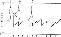
すなわち画像符号化装置から固定のビツトレートで符号化データを伝送する場合、図1に示すように、指定されたビツトレートで画像データのビツトストリームがVBVバツフアに入力されるときに、このVBVバツフア内のデータ占有量がアンダフロー及びオーバフローしないような状態で、VBVバツフアから画像データを発生させる。
画像復号装置においては、画像符号化装置から伝送されるビツトストリームをVBVバツフアを通して1フレーム分の画像データを単位として復号化する。かくして画像符号化装置から伝送される符号化データのビツトレートが一定であつても、データ量が異なるピクチヤを確実に復号化できる。例えばフレーム内の画像データを用いて符号化したフレーム(すなわちイントラ符号化されたIピクチヤは、時間的に前後のフレームから動き補償を用いて符号化されたフレーム(すなわちPピクチヤ又はBピクチヤ)に比してフレーム当たりの符号量が多いが、VBVバツフアアンダフローやオーバフローをしない状態で復号化ができれば、各ピクチヤを確実に復号化できる。
図1において、各線分xの傾きは伝送するデータストリームの固定ビツトレートを示し、当該各線分xの各位置x1はVBVバツフアにおけるデータ占有量を表している。また線分yは1フレーム分のデータがVBVバツフアからIピクチヤ、Bピクチヤ及びPピクチヤとして読み出されたことにより、VBVバツフアのデータ占有量が急に減少することを示している。
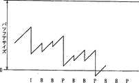
ところが図2に示すように、所定のデータ占有量の範囲を越えるデータをもつたピクチヤがVBVバツフアから発生したとき、VBVバツフアにアンダフローが発生する。このことは、目標符号発生量はレート制御によつて設定されてはいるが、伝送されて来た画像の複雑さや、動きの激しさによつて実際の符号発生量が目標符号発生量より大きくなつた場合に当該ピクチヤを復号するためのデータが不足(図中「0」以下の部分に相当)するので画像を復号できないことを意味する。
このVBVバツフアの動作については、ISO(International Organization for Standardization)/IEC(International Electrotechnical Commission)13818-2(MPEG2のビデオパート)のAnnexCに記述されているが、VBVバツフアにアンダフロー及びオーバフローが発生したときの画像復号装置の動作については記述されていない。
VBVバツフアにアンダフローが発生すること防止する方法として、VBVバツフアに固定のしきい値を設定し、VBVバツフア内のデータ占有量がこのしきい値を下回るようなピクチヤについてはスキツプする(画像に対する符号化処理を停止する)ことにより、VBVバツフアにアンダフローが発生することを防止する方法が提案されている。
ところがこの方法では、どの画像符号化タイプのピクチヤに対しても同じようにスキツプ処理が行われる可能性がある。この場合、特に復号の際の画質上最も重要な画像データを含むIピクチヤはPピクチヤ及びBピクチヤより符号発生量(すなわちデータ量)が多いため、Pピクチヤ及びBピクチヤよりもスキツプ処理される可能性が高くなることが考えられる。このようにIピクチヤがスキツプされた場合には、スキツプされたIピクチヤを予測画像とするPピクチヤ及びBピクチヤの画質に影響が及ぶため全体の画質が劣化するおそれがあつた。
発明の開示
本発明は以上の点を考慮してなされたもので、画質を劣化させずに復号化保証用バツフアにおけるアンダフローの発生を防止することができる画像符号化装置及び画像符号化方法を提案しようとするものである。
かかる課題を解決するため本発明においては、入力画像信号を符号化処理して得た符号化画像データを復号手段の入力バツフアに所定のビツトレートで伝送する画像符号化装置において、入力画像信号をIピクチヤ、Pピクチヤ又はBピクチヤを構成する符号化画像データに符号化処理して入力バツフアに伝送する符号化手段と、入力バツフアを復号化保証用の仮想バツフアとして、当該仮想バツフアのデータ占有量を判定するために、Iピクチヤ、Pピクチヤ及びBピクチヤの符号化処理に対応する第1のしきい値、第2のしきい値及び第3のしきい値を設定し、符号化手段によつてIピクチヤ、Pピクチヤ又はBピクチヤの符号化処理時の発生符号量が、当該Iピクチヤ、Pピクチヤ又はBピクチヤの復号時における仮想バツフアのデータ占有量が第1のしきい値、第2のしきい値又は第3のしきい値より下回わる関係になつたとき、現在実行している符号化処理を停止するように符号化手段をスキツプ制御する制御手段とを具え、第1のしきい値、第2のしきい値及び第3のしきい値の値は、当該第1のしきい値、第2のしきい値及び第3のしきい値の順に高くなるように設定されている。
かくして画質に対する影響を極力抑えながら、画像復号化装置における入力バツフアに対応する仮想的なバツフアのアンダフローを防止することができるという効果を奏する。
【図面の簡単な説明】
図1はVBVバツフアにおけるデータ占有量の推移の説明に供する略線図である。
図2はVBVバツフアにおけるアンダフローの説明に供する略線図である。図3は本発明の第1の実施の形態である画像符号化装置及び画像復号装置の概略構成を示すブロツク図である。
図4はVBVバツフアにおけるデータ占有量が第1のしきい値を下回つた場合のデータ占有量の推移の説明に供する略線図である。
図5はVBVバツフアにおけるデータ占有量が第2のしきい値を下回つた場合のデータ占有量の推移の説明に供する略線図である。
図6はVBVバツフアにおけるデータ占有量が第3のしきい値を下回つた場合のデータ占有量の推移の説明に供する略線図である。
図7は符号化制御回路の動作の説明に供するフローチヤートである。
図8は本発明の第2の実施の形態である画像符号化装置の概略の構成を示すブロツク図である。
図9は図8の画像符号化装置の詳細な構成を示すブロツク図である。
図10は図9の符号化制御部の動作の説明に供するフローチヤートである。
発明を実施するための最良の形態
(1) 第1の実施の形態
図3において、1は全体として画像符号化装置を示し、入力端子W1から入力した入力画像信号S1が画像タイプ指定回路2に入力される。
画像タイプ指定回路2は入力される画像信号S1の各フレームをIピクチヤ、Pピクチヤ又はBピクチヤのうちのどの画像符号化タイプのピクチヤとして処理するかを指定して画像符号化並替え回路3に送出する。この画像符号化装置1は、例えば15個のフレームをグループ・オブ・ピクチヤ(GOP)として、これを1単位として符号化処理を実行する。
画像符号化順序並替え回路3は指定された画像符号化タイプに従つて各フレームを符号化する順番に並び替えて画像信号S2としてスキヤンコンバータ4に送出すると共に、画像符号化タイプデータS3を予測モード決定回路5、動きベクトル検出回路6及び符号化制御回路7に送出する。また画像符号化並替え回路3は現在符号化されているフレームの動きベクトルを検出するために現在画像と、当該現在画像より時間的に過去にある画像(以下、これを過去参照画像と呼ぶ)及び又は現在画像より時間的に未来にある画像(以下、これを未来参照画像と呼ぶ)とを表す画像信号S4を動きベクトル検出回路6に送出する。
スキヤンコンバータ4は、入力されるフレームをブロツクフオーマツトの信号に変換し、この1フレームの信号を16ラインを1単位としてN個のスライスに区分する。各スライスは16×16の画素に対応する輝度信号によつて構成されるM個のマクロブロツクに分割される。これら各マクロブロツクにはアドレス(可変長符号(インクリメント値))が付加されており、このアドレスは各マクロブロツクの位置を表すものである。この場合、ピクチヤ中で最初に伝送されるマクロブロツクのアドレスは番号そのものを表し、これに続くマクロブロツクのアドレスは、当該マクロブロツクの絶対アドレスとその1つ前に伝送されたマクロブロツクの絶対アドレスとの差を表している。
動きベクトル検出回路6は画像信号S2の各フレームに同期した画像符号化タイプデータS3に従つて各フレームの画像データをフレーム内符号化によるIピクチヤ、フレーム間順方向予測符号化によるPピクチヤ又は双方向予測符号化によるBピクチヤとして処理する。かくして、Iピクチヤとして処理されるフレームの画像データは、動きベクトル検出回路6から過去参照画像を格納する過去参照画像メモリ(図示せず)に格納され、Bピクチヤとして処理されるフレームの画像データは現在画像を格納する現在画像メモリ(図示せず)に格納され、Pピクチヤとして処理されるフレームの画像データは未来参照画像を格納する未来参照画像メモリ(図示せず)に格納される。
ここで次のタイミングにおいて、Bピクチヤ又はPピクチヤとして処理すべきフレームが動きベクトル検出回路6に入力されたとき、これまでに未来参照画像メモリに格納されていた最初のPピクチヤの画像データは過去参照画像メモリに格納される。また次のBピクチヤの画像データは現在画像メモリに格納され、次のPピクチヤの画像データは未来参照画像メモリに格納される。以降このような動作が順次繰り返される。
動きベクトル検出回路6は順方向予測における動きベクトル及びそのときの動きベクトル推定残差でなる動きベクトルデータS5を予測モード決定回路5に送出する。また動きベクトル検出回路6は、Bピクチヤの場合には、逆方向予測における動きベクトル及びそのときの動きベクトル推定残差でなる動きベクトルデータS5を送出する。
予測モード決定回路5はイントラモード、順方向予測モード、逆方向予測モード又は双方向予測モードのうちどの予測モードを選択するかを決定する。
ここでイントラモードは、符号化対象となるフレームの画像データをそのまま伝送データとして伝送する処理であり、順方向予測モードは、過去参照画像との予測残差と順方向動きベクトルとを伝送する処理である。また逆方向予測モードは、未来参照画像との予測残差と逆方向動きベクトルとを伝送する処理であり、双方向予測モードは、過去参照画像と未来参照画像の2つの予測画像の平均値との予測残差と順方向及び逆方向の2つの動きベクトルとを伝送する処理である。Bピクチヤの場合には、これら4種類の予測モードをマクロブロツク単位で切り換える。
予測モード決定回路5は画像符号化並替え回路3から送出される画像符号化タイプデータS3に基づいて、Iピクチヤの場合にはイントラモードを選択し、Pピクチヤの場合にはイントラモード又は順方向予測モードのいずれかの予測モードを選択し、Bピクチヤの場合には、イントラモード、順方向予測モード、逆方向予測モード又は双方向予測モードのうちいずれかの予測モードを選択し、選択した予測モードを表す予測モードデータS6を演算回路8に送出する。
演算回路8はスキヤンコンバータ4より読み出されたマクロブロツクS7に対して、予測モードデータS6に基づいてイントラ、順方向予測、逆方向予測又は双方向予測の演算を行う。
演算回路8はマクロブロツクS7としてIピクチヤとして処理すべきフレームの画像データが入力された場合、当該画像データをイントラ符号化してDCT(Discrete Cosine Transform、離散コサイン変換)変換回路9に送出する。DCT変換回路9はイントラ符号化された画像データをDCT変換係数に変換して量子化回路10に送出する。
量子化回路10は各DCT変換係数を符号化制御回路7から指定された量子化ステツプで量子化して可変長符号化回路11及び逆量子化回路12に送出する。
可変長符号化回路11は量子化された画像データ、予測モード決定回路5から送出される予測モードデータS6及び動きベクトル検出回路6から送出される動きベクトルデータS5を例えばハフマン符号などの可変長符号に変換して伝送路(図示せず)を介して画像復号装置13に伝送すると共に、符号化制御回路7に与える。また可変長符号化回路11は各マクロブロツクのインクリメント値をカウントする。
逆量子化回路12は量子化された画像データを量子化時における量子化ステツプに応じて逆量子化して逆DCT変換回路14に送出する。逆DCT変換回路14は逆量子化回路12からの出力を逆DCT変換処理をする。逆DCT変換回路14からの出力は演算器15を介してフレームメモリ16内の過去参照画像を格納する過去参照画像記憶部(図示せず)に格納される。
次に演算回路8にスキヤンコンバータ4からPピクチヤとして処理すべきフレームの画像データが入力され、予測モード決定回路5から送出される予測モードデータS6がイントラモードの場合、当該フレームの画像データは、上述のIピクチヤの場合と同様にイントラ符号化されてDCT変換回路9、量子化回路10及び可変長符号化回路11を介して画像復号装置13に伝送されると共に、符号化制御回路7に与えられ、さらに逆量子化回路12、逆DCT変換回路14及び演算器15を介してフレームメモリ16内の未来参照画像を格納する未来参照画像記憶部(図示せず)に格納される。
予測モードデータS6が順方向予測モードを表している場合には、フレームメモリ16の過去参照画像記憶部に格納されている画像データ(この場合Iピクチヤの画像データ)が読み出されて動き補償回路17に送出される。
動き補償回路17はこの画像データを動きベクトル検出回路6から送出される順方向の動きベクトルデータS5に対応して動き補償する。
すなわち動き補償回路17は、順方向予測モードの場合、フレームメモリ16の過去参照画像記憶部の読出しアドレスを、動きベクトル検出回路6が現在出力しているマクロブロツクの位置に対応する位置から順方向の動きベクトルデータS5に対応する分だけずらしてデータを読み出して予測参照画像を生成し、演算回路8及び演算器15に送出する。
演算回路8はスキヤンコンバータ4から送出される参照画像のマクロブロツクのデータS7から、動き補償回路17から送出された当該マクロブロツクに対応する予測参照画像の画像データを減算して、予測残差としての差分データを得、この差分データをDCT変換回路9に送出する。この差分データはDCT変換回路9、量子化回路10及び可変長符号化回路11を介して画像復号装置13に伝送されると共に、符号化制御回路7に与えられる。またこの差分データは逆量子化回路12及び逆DCT変換回路14によつて局所的に復号されて演算器15に送出される。
演算器15は逆DCT変換回路14から送出される差分データに、動き補償回路17から送出される予測参照画像の画像データを加算する。これにより局所的に復号したPピクチヤの画像データが得られる。このPピクチヤの画像データはフレームメモリ16内の未来参照画像を格納する未来参照画像記憶部に格納される。
次に演算回路8にスキヤンコンバータ4からBピクチヤとして処理すべきフレームの画像データが入力され、予測モード決定回路5から送出される予測モードデータS6がイントラモード又は順方向予測モードの場合、当該フレームの画像データは上述のPピクチヤの場合と同様に処理される。これに対して予測モードデータS6が逆方向予測モードに設定された場合には、フレームメモリ16の未来参照画像記憶部に格納されている画像データ(この場合Pピクチヤの画像データ)が読み出されて動き補償回路17に送出される。
動き補償回路17はこの画像データを動きベクトル検出回路6から送出される逆方向の動きベクトルデータS5に対応して動き補償する。
すなわち動き補償回路17は、逆方向予測モードのとき、フレームメモリ16の未来参照画像記憶部の読出しアドレスを、動きベクトル検出回路6が現在出力しているマクロブロツクの位置に対応する位置から動きベクトルデータS5に対応する分だけずらしてデータを読み出して予測参照画像を生成し、演算回路8及び演算器15に送出する。
演算回路8はスキヤンコンバータ4から送出される参照画像のマクロブロツクのデータから、動き補償回路17から送出された当該マクロブロツクに対応する予測参照画像の画像データを減算して予測残差としての差分データを得、この差分データをDCT変換回路9に送出する。
このとき、演算器15は逆DCT変換回路14から送出される差分データに、動き補償回路17から送出される予測参照画像の画像データを加算することにより、局所的に復号したBピクチヤの画像データを得る。
双方向予測モードの場合には、フレームメモリ16の過去参照画像記憶部に格納されている画像データ(この場合Iピクチヤの画像データ)と、未来参照画像記憶部に格納されている画像データ(この場合Pピクチヤの画像データ)とが読み出されて動き補償回路17に送出される。
動き補償回路17はこの画像データを動きベクトル検出回路6から送出される順方向の動きベクトル及び逆方向の動きベクトルでなる動きベクトルデータS5に対応して動き補償する。
すなわち動き補償回路17は、双方向予測モードの場合、フレームメモリ16の過去参照画像記憶部と未来参照画像記憶部の読出しアドレスを、動きベクトル検出回路6が現在出力しているマクロブロツクの位置に対応する位置から順方向の動きベクトル及び逆方向の動きベクトルでなる動きベクトルデータS5に対応する分だけずらしてデータを読み出して予測参照画像を生成し、演算回路8及び演算器15に送出する。
演算回路8はスキヤンコンバータ4から送出される参照画像のマクロブロツクのデータから、動き補償回路17から送出された当該マクロブロツクに対応する予測参照画像の画像データの平均値を減算して予測残差としての差分データを得、この差分データをDCT変換回路9に送出する。
このとき、演算器15は逆DCT変換回路14から送出される差分データに、動き補償回路17から送出される予測参照画像の画像データを加算することにより、局所的に復号したBピクチヤの画像データを得る。ここでBピクチヤは他の画像の予測画像として使用されないので、フレームメモリ16には格納されない。
画像復号装置13は画像符号化装置1から固定のビツトレートで伝送されるビツトストリームをデコーダバツフア18に一旦格納した後、所定のタイミングで当該デコーダバツフア18から1フレーム分の画像データを読み出して復号部19において順次復号し、復号されたフレームを原画像の順序に並び替えて例えばデイスプレイ上に表示させる。
ここでデコーダバツフア18は、画像符号化装置1から仮想的に考えた復号化保証用バツフア(すなわちVBVバツフア)を構成し、画像符号化装置1は、復号部19がデコーダバツフア18から画像データを読み出すタイミングが分かるようになされている。
この実施例の場合、符号化制御回路7は可変長符号化回路11から送出される可変長符号化された画像データの符号発生量をマクロブロツク単位で演算すると共にインクリメント値をカウントする。また符号化制御回路7は目標符号化発生量を表す量子化ステツプ制御信号S8を量子化回路10に与えることにより1フレーム当たりの符号発生量を制御する。
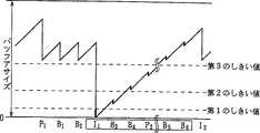
さらに符号化制御回路7はVBVバツフアとして機能するデコーダバツフア18におけるデータ占有量のしきい値として、第3のしきい値、第2のしきい値及び第1のしきい値を有する。これら第3、第2及び第1のしきい値は、それぞれBピクチヤ、Pピクチヤ及びIピクチヤに対応している。またこれらしきい値の値は、画像を復号する際の画像符号化タイプの重要度の低い順に高くなるように、第3のしきい値>第2のしきい値>第1のしきい値に設定されている。かくして、符号化制御回路7は、Bピクチヤが符号化されているときに、可変長符号化回路11から送出される画像データの符号発生量に基づき、デコーダバツフア18よつて形成されるVBVバツフアにおけるデータ占有量が第3のしきい値を下回るような符号量を有する画像データが発生した場合には、量子化回路10にスキツプ実行信号S9を送出して、当該符号化中のBピクチヤのこれ以降の画像データをマクロブロツク単位でスキツプさせその結果データ占有量の傾下を抑えるようになされている。
ここで、スキツプするとは、現在実行されている符号化処理を停止させることをいう。
このような処理をしたとき、デコーダバツフア18によつて形成されるVBVバツフア18におけるデータ占有量は、図4に示すように推移する。図4に示す太線部分は、画像データがスキツプされたことを示し、図5及び図6についても同様である。
この場合、量子化回路10はスキツプ信号S9を受けると、内部に設けられたスキツプスイツチをオン動作させることにより画像データをスキツプする。この場合、符号化制御回路7はスキツプするマクロブロツクについてのアドレス情報S10を可変長符号化回路11に送出する。量子化回路10からの符号(ビツト)発生はなくなる。また量子化回路10は画像データをスキツプしない場合には、スキツプスイツチをオフ動作させることにより画像データを量子化する。
ここで符号化制御回路7は、画像復号装置13の復号部19がデコーダバツフア18からデータを読み出すタイミングを知つており、しかも可変長符号化回路11からの送出される画像データの符号発生量を演算し、これによりデコーダバツフア18に現在格納されているデータ量を知ることができる。
可変長符号化回路11は画像データがスキツプされていない場合には、インクリメント値をカウントすると共にアドレス情報と共に画像データを符号化制御回路7及び画像復号装置13に伝送する。これに対して可変長符号化回路11は、画像データがスキツプされた場合には、インクリメント値はカウントするがスキツプされたマクロブロツクについてのアドレス情報は出力せず、行及び列方向に並べられた複数のマクロブロツクの行方向における最初のマクロブロツクのアドレス情報(以下、これを先頭アドレス情報と呼ぶ)と、行方向における最後のマクロブロツクのアドレス情報(以下、これを最終アドレス情報と呼ぶ)だけは可変長符号化して符号化制御回路7及び画像復号装置13に伝送する。
これにより符号化制御回路7及び画像復号装置13はどの画像符号化タイプの画像データがスキツプされたかを知ることができる。ここで可変長符号化回路11に対する先頭アドレス情報及び最終アドレス情報の指定は、符号化制御回路7が指定信号S10を可変長符号化回路11に送出することにより行われる。
また符号化制御回路7は、Pピクチヤが符号化されているときに、可変長符号化回路11から送出される画像データの符号発生量に基づき、デコーダバツフア18におけるデータ占有量が第2のしきい値を下回るような符号発生量を有する画像データが発生した場合には、量子化回路10にスキツプ実行信号S9を送出して、当該符号化中のPピクチヤのこれ以降の画像データをマクロブロツク単位でスキツプさせる。
ここで符号化制御回路7は、Pピクチヤをスキツプさせた場合には、デコーダバツフア18におけるデータ占有量がそれぞれ対応するしきい値を越えている場合でも、当該スキツプされたPピクチヤを予測画像として復号化の際に用いるBピクチヤ及びPピクチヤは全てスキツプさせるようになされている。これは、図5に示すように、PピクチヤP3が前のPピクチヤP2を予測画像としているためである。すなわちPピクチヤP2は符号化の途中からスキツプされているため、画像データとしては不十分なものとなり、このPピクチヤP2を用いて復号化される復号後のPピクチヤP3の画質が劣化するからである。このことはBピクチヤB5及びBピクチヤB6についても同様である。従つて次のIピクチヤの符号化まで画像データがスキツプされている。
また図5において、BピクチヤB3、BピクチヤB4、PピクチヤP3、BクピチヤB5及びBピクチヤB6がそれぞれスキツプされているのにもかかわらず、データ量が太線の分だけ減つているのは、上述した先頭アドレス情報及び最終アドレス情報が読み出されているからである。このことは図6についても同様である。
さらに符号化制御回路7は、Iピクチヤが符号化されているときに、可変長符号化回路11から送出される画像データの符号発生量に基づき、デコーダバツフア18におけるデータのバツフア占有量が第1のしきい値を下回るような符号量を有する画像データが発生した場合、量子化回路10にスキツプ実行信号S9を送出して、当該符号化中のIピクチヤのこれ以降の画像データをマクロブロツク単位でDC成分のみのマクロブロツクとして符号化する。この場合、符号化制御回路7は次のIピクチヤの符号化までBピクチヤ及びPピクチヤをスキツプさせるように量子化回路10を制御する。
これは、図6に示すように、例えばPピクチヤP2は前のIピクチヤI1を予測画像としているためである。すなわちIピクチヤI1は符号化の途中からDC成分のみの符号化とされているため、画像データとしては不十分なものとなり、このIピクチヤI1を用いて復号化される復号後のPピクチヤP2の画質が劣化するからである。このことは、IピクチヤI1やPピクチヤP2を復号化の際に用いるBピクチヤB3、BピクチヤB4、BピクチヤB5及びBピクチヤB6についても同様である。従つて次のIピクチヤの符号化まで画像データがスキツプされている。
ここで図4〜図6に示す太線は、結果としてスキツプされたマクロブロツク又はDC成分のみのイントラマクロプロックで構成されることになる。
また符号化制御回路7は、上述のように画像データをスキツプさせた場合、スキツプさせた分だけ、以降の画像データに対する目標符号発生量を多く割り当てるように、目標符号発生量制御信号S8によつて量子化回路10を制御する。この場合、符号化制御回路7は画像を復号する際の重要度が高い画像符号化タイプ、すなわちIピクチヤ、Pピクチヤの順に目標符号発生量を多く割り当てる。
画像復号装置13は、画像符号化装置1でピクチヤがスキツプされた場合でも、伝送されてくるアドレス情報に基づいてどのマクロブロツクがスキツプされたかを判別することができ、これによりスキツプされた場合には、前のフレームをそのまま表示するようになされている。
符号化制御回路7の動作について図7を用いて説明する。
符号化制御回路7は、ステツプSP1より動作を開始して、ステツプSP2において、これから符号化するピクチヤ(以下、これを符号化対象ピクチヤと呼ぶ)がどの画像符号化タイプかを画像符号化並替え回路3から送出される画像符号化タイプデータS3に基づいて判定した後、ステツプSP3に進む。
符号化制御回路7は、ステツプSP3において、スキツプ判定フラグがセツトされているピクチヤ(以下、これをスキツプピクチヤと呼ぶ)の画像符号化タイプと、符号化対象ピクチヤの画像符号化タイプとに基づいて、符号化対象ピクチヤをスキツプするか否かを判定する。ここでスキツプ判定フラグは、後述するように、スキツプピクチヤに対して設定されるフラグを表す。
このステツプSP3において、符号化対象ピクチヤをスキツプするか否かを判定するのは、スキツプピクチヤが符号化対象ピクチヤの予測画像であるか否かを判定するためである。すなわち上述したように、符号化対象ピクチヤの予測画像がスキツプされている場合には、この予測画像を用いて復号化されるピクチヤの画質に影響を与えるため、符号化対象ピクチヤを符号化しているときに、デコーダバツフア18におけるデータ占有量が当該符号化対象ピクチヤの画像符号化タイプに対応するしきい値を下回つていない場合でもスキツプさせる必要があるからである。例えばPピクチヤP3(図5)を符号化対象ピクチヤとした場合、当該PピクチヤP3の予測画像となるPピクチヤP2はスキツプされているからである。
ステヅプSP3において、符号化制御回路7が否定結果を得ると、ステツプSP4に進み、スキツプ判定フラグをリセツトする。ここでスキツプ判定フラグをリセツトするのは、ステツプ判定フラグをセツトしたままであると、スキツプを行つてはならないピクチヤの画像データがスキツプされることを防止するためである。
続いて符号化制御回路7はステツプSP5において目標符号発生量を計算した後、ステツプSP6に進んで符号化対象ピクチヤをマクロブロツク単位で符号化させる。次に符号化制御回路7はステツプSP7において、デコーダバツフア18における現在のデータ占有量を計算した後、ステツプSP8に進む。
ステツプSP8において、符号化制御回路7は、ステツプSP7において計算したデコーダバツフア18におけるデータ占有量が符号化対象ピクチヤに対応するしきい値を下回つているか否かを判定し、否定結果を得ると、ステツプSP9に進む。ステツプSP9において、符号化制御回路7は、符号化対象ピクチヤについて1フレーム分符号化されたか否かを判定し、否定結果を得るとステツプSP6に戻つて、ステツプSP6からステツプSP9までの処理ループを実行する。
符号化制御回路7は、ステツプSP3において符号化対象ピクチヤをスキツプさせると判定した場合にはステツプSP10に進み、先頭アドレス情報及び最終アドレス情報を除いて当該符号化対象ピクチヤをスキツプさせ、符号化対象ピクチヤがIピクチヤの場合にはDC成分のみのマクロブロツクとして符号化させる。また符号化制御回路7は、ステツプSP8においてデコーダバツフア18におけるデータ占有量が符号化対象ピクチヤに対応するしきい値を下回つた場合には、これ以降の符号化対象ピクチヤの画像データをマクロブロツク単位でスキツプさせる。
続いて符号化制御回路7は、ステツプSP11に進んで、符号化対象ピクチヤについて1フレーム分の符号化が終了したか否かを判定する。
符号化制御回路7はステツプSP11において否定結果を得ると、ステツプSP10に戻つて、ステツプSP10及びステツプSP11の処理ループを実行し、肯定結果を得るとステツプSP12に進む。ステツプSP12において、符号化制御回路7は、スキツプしたピクチヤに対して、対応するスキツプ判定フラグをセツトした後、ステツプSP2に戻り、画像信号S1を全て処理するまで上述の動作を繰り返す。
以上の構成において、この画像符号化装置1では、可変長符号化回路11からの画像データの符号発生量に基づき、Bピクチヤを符号化しているときに、デコーダバツフア18におけるデータ占有量が第3のしきい値を下回るような符号量を有する画像データが発生した場合には、当該符号化中のBピクチヤのこれ以降の画像データがマクロブロツク単位でスキツプされるので、デコーダバツフア18において次のPピクチヤの画像データのためのVBVバツフアのデータ占有量が確保される。
またこの画像符号化装置1では、可変長符号化回路11からの画像データの符号発生量に基づき、Pピクチヤを符号化しているときに、デコーダバツフア18におけるデータ占有量が第2のしきい値を下回るような符号量を有する画像データが発生した場合には、当該符号化中のPピクチヤのこれ以降の画像データがマクロブロツク単位でスキツプされるので、デコーダバツフア18においてIピクチヤの画像データのためのVBVバツフアのデータ占有量が確保される。
またPピクチヤがスキツプされた場合には、当該Pピクチヤを予測画像とするPピクチヤ及びBピクチヤが全てスキツプされるので、画質の劣化を防止することができる。
さらにこの画像符号化装置1では、可変長符号化回路11からの画像データの符号発生量に基づき、Iピクチヤを符号化しているときに、デコーダバツフア18におけるデータ占有量が第1のしきい値を下回るような符号量を有する画像データが発生した場合には、当該符号化中のIピクチヤのこれ以降の画像データがマクロブロツク単位でスキツプされるので、デコーダバツフア18において次のIピクチヤの画像データのためのVBVバツフアのデータ占有量が確保される。またIピクチヤがスキツプされた場合には、次のIピクチヤの符号化時まで全てのPピクチヤ及びBピクチヤがスキツプされるので、画質の劣化を防止することができる。
従つてこの画像符号化装置1では、画像を復号化する際の重要度が低い画像符号化タイプのピクチヤを優先的にスキツプさせているので、デコーダバツフア18において、次に重要度の高い画像符号化タイプのピクチヤのためのVBVバツフアのデータ占有量を確保することができる。
またこの画像符号化装置1では、画像を復号する際の重要度が低い画像符号化タイプのピクチヤを優先的にスキツプさせているので、画像を復号する際の重要度が高い画像符号化タイプのピクチヤに対してスキツプさせた分だけ目標符号発生量を多く割り当てることができ、画質の劣化を防止し得る。この場合、画像の絵柄が複雑なときには特に有効である。
さらに符号化装置1側で画像復号装置13側の画像のフリーズ状態を制御することができる。
以上の構成によれば、VBVバツフアにおけるデータ占有量のしきい値として、Bピクチヤ、Pピクチヤ及びIピクチヤにそれぞれ対応させて第3のしきい値、第2のしきい値及び第1のしきい値を設定すると共に、第3のしきい値、第2のしきい値、第1のしきい値の順にしきい値の値が大きくなるようにこれら第3、第2及び第1のしきい値の値を設定することにより、画像を復号する際の重要度の低い画像符号化タイプのピクチヤを優先的にスキツプさせる。
これにより、VBVバツフアにおいて、画像を復号化する際の重要度が高い画像符号化タイプのピクチヤのデータ占有量を優先的に確保することができ、その結果、画質を劣化させずにVBVバツフアにおけるアンダフローの発生を確実に防止することができる画像符号化装置を実現し得る。
なお上述の第1の実施の形態においては、可変長符号化回路11における符号化方式としてハフマン符号を用いた場合について述べたが、本発明はこれに限らず、可変長符号化回路11における符号化としてこの他種々の符号化方式を適用し得る。
また上述の第1の実施の形態においては、例えば15個のフレームをグループ・オブ・ピクチヤ(GOP)としこれを1単位として処理するようにした場合について述べたが、本発明はこれに限らず、GOPを構成するフレームの数としてこの他種々の数でGOPを構成してもよい。
さらに上述の第1の実施の形態においては、各画像をフレーム単位で符号化した場合について述べたが、本発明はこれに限らず、フイールド単位、又はフレーム単位とフイールド単位を混在させて符号化するようにしてもよい。すなわちノンインタレース走査方式に対応させ得るようにしてもよい。
さらに上述の第1の実施の形態においては、符号化対象となる画像の画像符号化タイプを判定する画像符号化タイプ判定手段として、画像符号化並替え回路3及び符号化制御回路7を用いた場合について述べたが、本発明はこれに限らず、画像符号化タイプ判定手段として、この他種々の画像符号化タイプ判定手段を適用し得る。
さらに上述の第1の実施の形態においては、画像符号化タイプ判定手段の出力に基づいて、第1、第2又は第3の画像を符号化する符号化手段として、画像符号化タイプ指定回路2、画像符号化順序並替え回路3、スキヤンコンバータ4、予測モード決定回路5、動きベクトル検出回路6、符号化制御回路7、演算回路8、DCT変換回路9、量子化回路10、可変長符号化回路11、逆量子化回路12、逆DCT変換回路14、演算器15、フレームメモリ16及び動き補償回路17を用いた場合について述べたが、本発明はこれに限らず、符号化手段としてこの他種々の第1の符号化手段を適用し得る。
さらに上述の第1の実施の形態においては、符号化された画像の符号発生量を演算し、当該演算結果に基づき、画像復号装置のバツフアにおける符号化された画像のデータ占有量が、第1、第2及び第3の画像にそれぞれ対応させて設定されたデータ占有量の第1、第2及び第3のしきい値のうち、現在符号化されている第1、第2又は第8の画像に対応する第1、第2又は第3のしきい値を下回るような符号発生量が発生した場合、現在符号化されている第1、第2又は第3の画像に対する符号化処理を停止させるように、符号化手段を制御する符号化制御手段として、符号化制御回路7を用いた場合について述べたが、本発明はこれに限らず、符号化制御手段としてこの他種々の符号化制御手段を適用し得る。
さらに上述の第1の実施の形態においては、画像データを3つの符号化タイプ、すなわちIピクチヤ、Pピクチヤ及びBピクチヤの画像に符号化するようにしたが、本発明はこれに限らず、3つの符号化タイプのうちから2つの符号化タイプ、すなわちIピクチヤ及びPピクチヤ、又はIピクチヤ及びBピクチヤを用いて画像を符号化するようにしても、上述の第1の実施の形態と同様の効果を得ることができる。
因に、VBVバツフアにおけるデータ占有量のしきい値として、Iピクチヤに対応する第1のしきい値を設定すると共に、Pピクチヤ又はBピクチヤに対応する第2又は第3のしきい値として第1のしきい値より大きい値のしきい値を設定するようにしたことにより、画像を復号化する際にIピクチヤより重要度の低いPピクチヤ又はBピクチヤを優先的にスキツプさせることができる。
これにより、VBVバツフアにおいて、画像を復号化する際の重要度が高い画像符号化タイプのピクチヤのデータ占有量を優先的に確保することができ、その結果、画質を劣化させずにVBVバツフアにおけるアンダフローの発生を確実に防止することができる画像符号化装置を実現し得る。
(2) 第2の実施の形態
図8において、画像符号化装置25は、入力画像信号S25をエンコーダ制御部26において圧縮符号化のための前処理等の処理をした後、FIFO(先入れ先出し)メモリ27において出力データを所定時間だけ遅延する。このFIFOメモリ12の出力データは符号化手段としてのエンコーダ28によつて、ピクチヤごとに画像符号化タイプ、すなわちピクチヤタイプに応じた符号化方法によつて圧縮符号化されて、圧縮画像データS26として出力される。
エンコーダ28には動き検出回路30によつてエンコーダ制御部26の出力データに基づいて検出された動きベクトルが与えられ、かくしてエンコーダ28から出力される発生ビツト量データS27と、エンコーダ制御部26から出力されるイントラACデータS28と、動き検出回路30から出力されるME残差データS29とに基づいて符号化制御部31によつて制御される。
図8に示す画像符号化装置25は、圧縮符号化する前の画像データの特徴に基づいて発生符号量の制御を行うフイードフオワード型のレート制御を行うように構成されている。
ここで、ME残差とは、動き予測誤差をピクチヤ全体について絶対値和あるいは自乗和したものであり、ME残差データS29は、ME残差を求めるためのデータである。
符号化制御部31は、互いにバス32を介して接続されたCPU(中央処理装置)33、ROM(read only memory)34及びRAM(randam access memory)35を有するコンピユータによつて構成され、CPU33が、RAM35をワーキングエリアとして、ROM34に格納されたプログラムを実行することによつて、符号化制御部31における各機能を実現する。ROM34は、本発明に係る画像符号化制御用プログラムを記憶したものであり、IC(集積回路)でも良いし、ハードデイスク、フロツピイデイスク等の磁気デイスクを記録媒体とする記憶装置でも良いし、CD(コンパクトデイスク)−ROM等の光デイスクを記録媒体とする記憶装置でも良いし、その他の種類の記録媒体を用いる記憶装置でも良い。いずれの場合にも、ICや種々の記録媒体は、本発明にかかる画像符号化制御用プログラムを記録した媒体に相当する。
エンコーダ制御部26は、図9に示すように、入力画像信号S25を入力し、符号化する順番に従つてピクチヤ(Iピクチヤ、Pピクチヤ、Bピクチヤ)の順番を並べ替える画像並べ替え回路41と、この画像並べ替え回路41の出力データを入力し、フレーム構造かフイールド構造かを判別し、判別結果に応じた走査変換及び16×16画素のマクロブロツク化を行う走査変換・マクロブロツク化回路42と、この走査変換・マクロブロツク化回路42の出力データを入力し、IピクチヤにおけるイントラACを算出し、イントラACデータS28を符号化制御部31に送ると共に、走査変換・マクロブロツク化回路42の出力データをFIFOメモリ27及び動き検出回路30に送るイントラAV演算回路43とを有する。
ここで、イントラACは、Iピクチヤにおいて、8×8画素のDCT変換(離散コサイン変換)ブロツク内の各画素の画素値とDCT変換ブロツク内の画素値の平均値との差分の絶対値の総和として定義され、絵柄の複雑さを表すものである。
エンコーダ28は、減算回路44において、FIFOメモリ27の出力データと予測画素データとの差分をとり、この減算回路44の出力データに対して、DCT変換回路45においてDCT変換ブロツク単位でDCT変換を行うことにより、DCT変換係数を出力し、このDCT変換回路45の出力データを量子化回路46によつて量子化した後、可変長符号化回路47によつて可変長符号化する。この可変長符号化回路47の出力データはバツフアメモリ48によつて一旦保持され、一定のビツトレートのビツトストリームからなる圧縮画像データS26として出力される。
量子化回路46の出力データは逆量子化回路49によつて逆量子化され、この逆量子化回路49の出力データに対して逆DCT変換回路50が逆DCT変換を行う。この逆DCT変換回路50の出力データは加算回路51によつて予測画像データとを加算され、この加算回路51の出力データを動き補償回路52において保持し、動き検出回路30から送られる動きベクトルに応じて動き補償を行つて予測画像データを減算回路44及び加算回路51に出力する。
バツフアメモリ48は、可変長符号化回路47より発生されるビツト量を表す発生ビツト量データS27を符号化制御部31に送るようになつている。
動き検出回路30は、エンコーダ制御部26の出力データに基づいて、圧縮符号化の対象となるピクチヤの注目マクロブロツクと、参照されるピクチヤにおいて注目マクロブロツクとの間の画素値の差分の絶対値和又は自乗和が最小となるマクロブロツクを探して、動きベクトルを検出して動き補償回路52に送る。また、動き検出回路30は、動きベクトルを求める際に、最小となつたマクロブロツク間における画素値の差分の絶対値和又は自乗和を、ME残差データS29として符号化制御部31に送る。
符号化制御部31は、動き検出回路30からのME残差データS29をピクチヤ全体について足し合わせた値であるME残差をME残差計算部61において算出し、このME残差計算部61によつて算出されたME残差とイントラAC演算回路43からのイントラACデータS28とに基づいて、符号化難易度計算部42によつてピクチヤの符号化の難易度を表す符号化難易度を算出する。バツフアメモリ48からの発生ビツト量データS27はこの第2の実施の形態に係る画像符号化装置25によつて圧縮符号化された画像データを伸張する画像復号化装置における入力バツフアに対応する仮想的なバツフアであるVBVバツフアのデータ占有量を、VBVバツフア占有量計算部62において算出する。なお、ME残差は、映像の動きの速さ及び絵柄の複雑さを表す。
符号化制御部31は、さらに、符号化難易度計算部63によつて算出された符号化難易度とVBVバツフア占有量計算部62によつて算出されたVBVバツフアの占有量とに基づいて目標符号量を決定すると共に、VBVバツフアのアンダフローを防止するために画像に対する符号化処理を停止するスキツプを行うか否かの判定を行う目標符号量決定部64を有し、エンコーダ28における発生符号化量が目標符号量決定部64によつて決定された目標符号量となるように量子化回路46における量子化特性値に対応する量子化インデツクスを量子化インデツクス決定部65において決定して量子化回路46に送る。かくして目標符号量決定部64によつてスキツプを行うと判定された場合には、スキツプ制御部66が量子化回路46及び可変長符号化回路47を制御してスキツプを行わせる。
ここで、符号化難易度について説明する。符号化難易度は、ピクチヤの符号化の難易度を表すものであるが、これは、同じ画質を保つために必要なデータ量の比率と言い換えることができる。符号化難易度を数値化する方法は種々考えられるが、この第2の実施の形態では、IピクチヤについてはイントラACを用いて符号化難易度を求め、Pピクチヤ及びBピクチヤについてはME残差を用いて符号化難易度を求める。前述のように、イントラACは絵柄の複雑さを表し、ME残差は映像の動きの速さ及び絵柄の複雑さを表し、これらは符号化の難易度と強い相関があるので、イントラACやME残差を変数とする一次関数等により、イントラACやME残差から符号化難易度を算出することができる。
次に、符号化難易度に基づいてVBVバツフアのアンダフローの危険度を判定する方法について説明する。すでに説明したように、VBVバツフアのアンダフローが発生するのは、目標符号量に対して発生符号量が大きく上回るような場合である。このようなことは、ビツトレートに対して入力画像の符号化難易度が非常に大きい場合に生じる。そこで、VBVバツフアのアンダフローの危険度を判定するためのパラメータとしては、ビツトレートに対する符号化難易度の比率を用いるのが適当である。また、さらに、VBVバツフアのアンダフローの危険度を判定するためには、これから符号化する予定の数枚以内のピクチヤにおける、上記ビツトレートに対する符号化難易度の比率を見ることが重要である。これは、符号化難易度は、ピクチヤタイプによつて変動するからである。そこで、この第2の実施の形態では、VBVバツフアのアンダフローの危険度を判定するためのパラメータとして、次式によつて定義されるパラメータxを用いる。
x=ΣDk/G ……(1)
ここで、Dkはピクチヤkの符号化難易度を表し、kはピクチヤの符号化順を表し、次に符号化する予定のピクチヤをk=1とする。Σはk=1からN(Nは1GOP(グループ・オブ・ピクチヤ)分のピクチヤの枚数)までの総和を意味する。また、Gは次式、
G=(〔ビツトレート〕×N)/〔ピクチヤレート〕 ……(2)
によつて定義される。
(2)式において、〔ビツトレート〕は、通信回線の伝送容量や記録媒体の記録容量に基づいて決められる1秒当たりのデータ量(ビツト量)を表し、〔ピクチヤレート〕は、1秒当たりのピクチヤの枚数(例えばNTSC圏では30、PAL圏では25)である。従つて、Gは、N枚分のピクチヤに対応する時間に割り当てられるデータ量(ビツト量)を表し、xは、N枚分のピクチヤに対応する時間に割り当てられるデータ量(ビツト量)に対するN枚分のピクチヤの符号化難易度Dkの和の比率を表す。
なお、必ずしもN枚分のピクチヤを用いてxを求める必要はなく、Nより大きい数や小さい数の枚数分のピクチヤを用いてxを求めるようにしても良い。ただし、Nよりもあまり大きい数をとるとアンダフローの危険度の判定が精度が落ち、Nよりもあまり小さい数をとるとパラメータxの変動が大きくなることに留意する必要がある。
次に、第2の実施の形態に係る画像符号化装置25の動作について説明する。入力画像信号S25は、エンコーダ制御部26に入力される。エンコーダ制御部26では、まず、画像並べ替え回路41によつて、符号化する順番に従つてピクチヤ(Iピクチヤ、Pピクチヤ、Bピクチヤ)の順番を並べ替え、次に、走査変換・マクロブロツク化回路42によつて、フレーム構造かフイールド構造かを判別し、判別結果に応じた走査変換及びマクロブロツク化を行い、次に、Iピクチヤの場合には、イントラAC演算回路43によつてイントラACを算出してイントラACデータS28を符号化制御部31に送る。また、走査変換・マクロブロツク回路42の出力データは、イントラAC演算回路43を経て、FIFOメモリ27及び動き検出回路30に送られる。
FIFOメモリ27は、符号化難易度計算部63において、符号化が終了したピクチヤに引き続くN枚分のピクチヤの符号化難易度を算出するのに必要な時間だけ、入力した画像データを遅延して、エンコーダ28に出力する。動き検出回路30は、動きベクトルを検出して動き補償回路52に送ると共に、ME残差データS29をME残差計算部61に送る。
Iピクチヤの場合には、エンコーダ28では、減算回路44において予測画像データとの差分をとることなく、FIFOメモリ27の出力データをそのままDCT変換回路45に入力してDCT変換を行い、量子化回路46によつてDCT変換係数を量子化し、可変長符号化回路47によつて量子化回路46の出力データを可変長符号化し、バツフアメモリ48によつて可変長符号化回路47の出力データを一旦保持し、一定のビツトレートのビツトストリームからなる圧縮画像データS26として出力する。
また、逆量子化回路49によつて量子化回路46の出力データを逆量子化し、逆DCT変換回路50によつて逆量子化回路49の出力データに対して逆DCT変換を行い、逆DCT変換回路50の出力画像データを加算回路51を介して動き補償回路52に入力して保持させる。
Pピクチヤの場合には、エンコーダ28では、動き補償回路52によつて、保持している過去のIピクチヤ又はPピクチヤに対応する画像データと動き検出回路30からの動きベクトルとに基づいて予測画像データを生成し、予測画像データを減算回路44及び加算回路51に出力する。また、減算回路44によつて、FIFOメモリ27の出力データと動き補償回路52からの予測画像データとの差分をとり、DCT変換回路45によつてDCT変換を行い、量子化回路46によつてDCT変換係数を量子化し、可変長符号化回路47によつて量子化回路46の出力データを可変長符号化し、バツフアメモリ48によつて可変長符号化回路47の出力データを一旦保持し圧縮画像データS26として出力する。また、逆量子化回路49によつて量子化回路46の出力データを逆量子化し、逆DCT変換回路50によつて逆量子化回路49の出力データに対して逆DCT変換を行い、加算回路51によつて逆DCT変換回路50の出力データと予測画像データとを加算し、動き補償回路52に入力して保持させる。
Bピクチヤの場合には、エンコーダ28では、動き補償回路52によつて、保持している過去及び未来のIピクチヤ又はPピクチヤに対応する2つの画像データと動き検出回路30からの2つの動きベクトルとに基づいて予測画像データを生成し、予測画像データを減算回路44及び加算回路51に出力する。また、減算回路44によつて、FIFOメモリ27の出力データと動き補償回路52からの予測画像データとの差分をとり、DCT変換回路45によつてDCT変換を行い、量子化回路46によつてDCT変換係数を量子化し、可変長符号化回路47によつて量子化回路46の出力データを可変長符号化し、バツフアメモリ48によつて可変長符号化回路47の出力データを一旦保持し、圧縮画像データS26として出力する。なお、Bピクチヤは動き補償回路52に保持させない。
なお、バツフアメモリ48は可変長符号化回路47より発生されるビツト量を表す発生ビツト量データS27を符号化制御部31に送る。
次に、図10のフローチヤートを参照して、符号化制御部31の動作について説明する。この動作では、まず、符号化難易度計算部63によつて、イントラAC演算回路43からのイントラACデータS28とME残差計算部61で算出したME残差より、符号化難易度を計算し、パラメータxを求める(ステツプSP21)。なお、パラメータxは、今から符号化する予定のピクチヤに引き続くN枚分のピクチヤの符号化難易度に基づいて算出される。
次に、スキツプフラグが“1”か否かを判断する(ステツプSP22)。スキツプフラグは、“1”のとき、今から符号化する予定のピクチヤをスキツプすることを示し、“0”のとき、今から符号化する予定のピクチヤをスキツプしないことを示す。
スキツプフラグが“0”の場合(ステツプSP22において否定結果が得られた場合)には、目標符号量決定部64によつて、パラメータxとVBVバツフア占有量計算部62によつて算出されているVBVバツフアの占有量とに基づいて、ピクチヤjの目標符号量を計算し(ステツプSP23)、量子化インデツクス決定部65に送る。なお、ピクチヤjは、今から符号化するピクチヤを意味する。
次に、量子化インデツス決定部65によつて、エンコーダ28における発生符号量が目標符号量決定部64によつて決定された目標符号量となるように量子化回路46における量子化特定値に対応する量子化インデツクスを決定し、量子化回路46に送る。これに応じて、ピクチヤjの符号化が行われる(ステツプSP24)。
一方、スキツプフラグ“1”の場合(ステツプSP22において肯定結果が得られた場合)には、目標符号量決定部64は、ピクチヤjをスキツプすることをスキツプ制御部66に指示し、これに応じて、スキツプ制御部66は、前のフレームを表示するように処理する(ステツプSP25)。すなわち、スキツプ制御部66は、量子化回路46を制御してマクロブロツク単位でスキツプを行わせると共に、可変長符号化回路47に対してスキツプするマクロブロツクのアドレス情報を送る。これに応じて、可変長符号化回路47は、スキツプするための情報を符号化して出力する。このようにして、ピクチヤjは、スキツプされたマクロブロツクであるスキツプマクロブロツクで構成されるピクチヤとして符号化される。
ステツプSP24又はステツプSP25が終了したら、VBVバツフア占有量計算部62によつて、ステツプSP24又はステツプSP25による発生ビツト量からVBVバツフアの占有量Bjを計算する(ステツプSP26)。なお、VBVバツフアの占有量Bjは、ピクチヤjの符号化前のVBVバツフアの占有量からピクチヤjによる発生ビツト量を引き、Iピクチヤ間の時間にVBVバツフアに蓄積されるビツト量を加算することによつて得ることができる。次に、次のピクチヤのピクチヤタイプを判定する(ステツプSP27)。ピクチヤタイプがBピクチヤの場合には、VBVバツフアの占有量BjがBピクチヤに対する占有量判定用しきい値Th(B)より小さいか否かを判別する(ステツプSP28)。ピクチヤタイプがPピクチヤの場合には、VBVバツフアの占有量BjがPピクチヤに対する占有量判定用しきい値Th(P)より小さいか否かを判断する(ステツプSP29)。ピクチヤタイプがIピクチヤの場合には、VBVバツフアの占有量BjがIピクチヤに対する占有量判定用しきい値Th(I)より小さいか否かを判断する(ステツプSP30)。なお、占有量判定用しきい値は、Th(B)>Th(P)>Th(I)となるように設定されている。
BjがTh(B)より小さくない場合(ステツプSP28において否定結果が得られる場合)、BjがTh(P)より小さくない場合(ステツプSP29において否定結果が得られた場合)又はBjがTh(I)より小さくない場合(ステツプSP30において否定結果が得られる場合)は、次のピクチヤをスキツプする必要がないので、スキツプフラグを“0”にする(ステツプSP31)。
BjがTh(B)より小さい場合(ステツプSP28において肯定結果が得られる場合)、BjがTh(P)より小さい場合(ステツプSP29において肯定結果が得られた場合)又はBjがTh(I)より小さい場合(ステツプSP30において肯定結果が得られた場合)は、パラメータxが所定の符号化難易度判定用しきい値Th(x)を越えているか否かを判断する(ステツプSP32)。なお、しきい値Th(x)は、目標符号量に対して発生符号量が大きく上回つてしまうほど難しい絵柄か否かを判別するためのしきい値である。xがTh(x)を越えていない場合(N)は、絵柄は今後さほど難しくないことを意味し、次のピクチヤをスキツプする必要がないので、スキツプフラグを“0”にする(ステツプSP31)。逆に、xがTh(x)を越えている場合(肯定結果が得られる場合)は、今後も難しい絵柄が続くことを意味するので、この場合はVBVバツフアのアンダフローの危険性が高いと判断して、次のピクチヤをスキツプするために、スキツプフラグを“1”にする(ステツプSP33)。
スキツプフラグの設定(ステツプSP31、ステツプSP33)が終了したら、次のピクチヤの処理のために、j+1を新たなjとして(ステツプSP34)、メインルーチンにリターンする(ステツプSP35)。
以上説明したように、第2の実施の形態に係る画像符号化装置25によれば、ピクチヤタイプ別にVBVバツフアの占有量判定用しきい値を設定し、Bピクチヤ、Pピクチヤ、Iピクチヤの順に優先的にスキツプするようにすると共に、符号化が終了したピクチヤに引き続く数枚のピクチヤの符号化難易度に基づいてスキツプを行うか否かを判定するようにしたので、入力画像の絵柄が難しくなり、VBVバツフアのアンダフローが発生しそうな場合に、画質に対する影響の少ないBピクチヤを優先的にスキツプすると共に、実際にはVBVバツフアのアンダフローが発生しないような場合にはピクチヤのスキツプを行わないようにすることができ、画質に対する影響を極力抑えながら、VBVバツフアのアンダフローを防止することができる。
なお、本発明は、上述の第2の実施の形態に限定されず、例えば、符号化難易度に基づいてスキツプを行うか否かを判定する際に、実施の形態で用いたパラメータxの他に、符号化難易度が増加傾向にあるのか減少傾向にあるのかという変化傾向の情報も加えて判定することで、今後の入力画像の絵柄の難しさの予測精度を更に向上させて、スキツプを行うか否かの判定をより適切に行うことができる。すなわち、例えば、今は符号化難易度が大きくても符号化難易度が減少傾向にある場合にはスキツプを行わなくともVBVバツフアのアンダフローが発生しない場合もあるので、このような場合にはスキツプを行わないようにすることでスキツプを極力少なくすることが可能となる。なお、符号化難易度の変化傾向の情報は、例えば、時系列的に求まつた符号化難易度を最小自乗法等により直線近似し、その傾きから求めることができる。この場合、符号化難易度の変化傾向の情報は、例えば、図9における符号化難易度計算部63において求める。
また、上記第2の実施の形態では、図8に示したように、エンコーダ28の他に別のエンコーダを設けることなく、圧縮符号化する前の画像データの特徴に基づいて発生符号量の制御を行うフイードフオワード型のレート制御を行う構成としたが、本発明は、圧縮符号化後のデータ量を見積もるためにエンコーダ28とは別の1バス目のエンコーダを設けて、この1バス目のエンコーダによつて圧縮符号化することによつて見積もられたデータ量に基づいて2バス目のエンコーダ28における発生符号量の制御を行うフイードフオワード型のレート制御を行う構成にも適用することができる。この場合には、1バス目のエンコーダによつて圧縮符号化することによつて得られた発生符号量に基づいて符号化難易度を求めることが可能である。
更に、本発明は、フイードフオワード型のレート制御を行う構成に限らず、既に圧縮符号化したピクチヤの符号化難易度に基づいて今後のピクチヤの符号化難易度を予測することで、MPEG方式の圧縮アルゴリズムとして有名なTM5(test model 5:ISO/IEC JTC/SC29(1993))等で代表されるような、過去に圧縮符号化して得られた発生符号量に基づいて発生符号量の制御を行うフイードバツク型のレート制御を行う構成にも適用することができる。この場合、例えば、過去に圧縮符号化したピクチヤのグローバル・コンプレキシテイ(Global Complexity)の傾向を分析し、直線近似等によつて今後の数枚分のピクチヤの符号化難易度を予測し、この予測した符号化難易度に基づいて実施の形態で用いたパラメータxの値を求め、実施の形態と同様にパラメータxの値に基づいてスキツプを行うか否かを判定するようにすれば良い。
なお、グローバル・コンプレキシテイとは、画面の複雑さを示すパラメータであり、符号化の難易度と相関があり、具体的にはピクチヤの圧縮符号化時の発生符号量とピクチヤの圧縮符号化時の平均量子化スケールコード(量子化特性値)との積として求められる(例えば、オーム社発行の「テレビジヨン学会マルチメデイア選書 MPEG」の第111ページ参照)。
また、フイードフオワード型のレート制御を行う構成において直線近似等によつて符号化難易度の変化傾向を求める場合や、フイードバツク型のレート制御を行う構成において直線近似等によつて今後の数枚分のピクチヤの符号化難易度を予測する場合において、シーンチエンジ時には符号化難易度の連続性がなくなるので、シーンチエンジ時には、符号化難易度の変化傾向を求める処理や符号化難易度を予測する処理をシーンチエンジ前までで完結させ、シーンチエンジ後に新たに処理を行うようにすれば、より精度が向上する。
また、符号化難易度は、実施の形態で挙げたイントラACやME残差等を用いたものに限らず、ピクチヤの符号化の難易度を表すものであれば、他のパラメータでも良い。
また、上記第2の実施の形態では、ピクチヤタイプ別にVBVバツフアの占有量判定用しきい値を変えているが、本発明はVBVバツフアの占有量判定用しきい値がピクチヤタイプによらずに一定である場合も含む。
産業上の利用可能性
本発明は、送信側で画像データを圧縮して送信すると共に、受信側で圧縮された画像データを伸張する通信システムや、画像データを圧縮して記録すると共に、再生時には圧縮された画像データを伸張して出力する圧縮画像記録再生装置等に利用できる。Technical field
The present invention relates to an image encoding device, an image encoding method, and a medium on which an image encoding program is recorded, and is particularly suitable when applied to a case where an image is compressed and transmitted to an image decoding device.
Background art
The image encoding device side encodes and compresses and transmits the image data, and the communication system that decompresses and decodes the image data transmitted on the image decoding device side, and compresses and records the image data. In addition, in a compressed image recording / reproducing apparatus that decompresses and outputs compressed image data during reproduction, as a method for compressing image data, for example, a bidirectional predictive code adopted in the MPEG (Moving Picture Experts Group) standard is used. Is used. In this bidirectional predictive encoding method, encoding efficiency is improved by using bidirectional prediction. In the bi-directional predictive coding method, three types of coding, that is, intra-frame coding, inter-frame forward predictive coding, and bi-directional predictive coding, are performed. coded picture), P picture (predictive coded picture) and B picture (bidirectionally predictive coded picture).
By the way, an image encoding apparatus that compresses and encodes image data using the bidirectional predictive encoding method adopted in the above-mentioned MPEG standard has the image decoding apparatus that expands the compression-encoded image data. In order to verify that the capacity of the input buffer is not broken, a decoding guarantee buffer, that is, a VBV (Video Buffering Verfier) buffer, in which the input buffer on the image decoding apparatus side is virtually considered from the image encoding apparatus side, is assumed. Therefore, the amount of data generated in the image coding apparatus is controlled so that the data occupancy of the VBV buffer does not overflow or underflow the allowable value (“Television Society Multimedia Selection MPEG” published by Ohm Corporation). (See page 115).
That is, when encoded data is transmitted from an image encoding device at a fixed bit rate, when a bit stream of image data is input to the VBV buffer at a specified bit rate, as shown in FIG. Image data is generated from the VBV buffer in a state where the data occupation amount does not underflow and overflow.
In the image decoding apparatus, the bit stream transmitted from the image encoding apparatus is decoded in units of image data for one frame through the VBV buffer. Thus, even if the bit rate of the encoded data transmitted from the image encoding apparatus is constant, pictures with different data amounts can be reliably decoded. For example, a frame encoded using image data in a frame (that is, an intra-coded I picture is a frame encoded using motion compensation from a preceding and succeeding frame (that is, a P picture or a B picture). Compared with a large amount of code per frame, each picture can be reliably decoded if it can be decoded without VBV buffer underflow or overflow.
In FIG. 1, the slope of each line segment x indicates a fixed bit rate of the data stream to be transmitted, and each position x of each line segment x.1 Represents the data occupation amount in the VBV buffer. The line segment y indicates that the data occupancy amount of the VBV buffer is abruptly reduced by reading out data for one frame from the VBV buffer as an I-picture, B-picture, and P-picture.
However, as shown in FIG. 2, when a picture having data exceeding the predetermined data occupancy range is generated from the VBV buffer, an underflow occurs in the VBV buffer. Although the target code generation amount is set by rate control, the actual code generation amount is larger than the target code generation amount due to the complexity of the transmitted image and the intensity of motion. In this case, it means that the image cannot be decoded because the data for decoding the picture is insufficient (corresponding to the portion below “0” in the figure).
The operation of the VBV buffer is described in Annex C of ISO (International Organization for Standardization) / IEC (International Electrotechnical Commission) 13818-2 (MPEG2 video part). Underflow and overflow occurred in the VBV buffer. The operation of the image decoding apparatus at that time is not described.
To prevent underflow from occurring in the VBV buffer, a fixed threshold is set for the VBV buffer, and skipping is performed for pictures whose data occupancy in the VBV buffer is below this threshold (for images). There has been proposed a method for preventing an underflow from occurring in the VBV buffer by stopping the encoding process.
However, in this method, there is a possibility that the skip process is similarly performed for any picture coding type picture. In this case, the I picture including the image data most important for image quality at the time of decoding has a larger amount of code generation (that is, the data amount) than the P picture and the B picture, and therefore can be skipped more than the P picture and the B picture. It is conceivable that the property becomes higher. When the I-picture is skipped in this way, the image quality of the P-picture and B-picture that use the skipped I-picture as a predicted image is affected, so that the overall picture quality may be deteriorated.
Disclosure of the invention
The present invention has been made in view of the above points, and intends to propose an image encoding apparatus and an image encoding method capable of preventing the occurrence of underflow in a decoding guarantee buffer without degrading the image quality. To do.
In order to solve such a problem, in the present invention, in an image encoding apparatus that transmits encoded image data obtained by encoding an input image signal to an input buffer of decoding means at a predetermined bit rate, the input image signal is converted to I Encoding means for encoding encoded image data constituting a picture, P picture, or B picture and transmitting it to the input buffer, and using the input buffer as a virtual buffer for guaranteeing decoding, the data occupancy of the virtual buffer is In order to determine, the first threshold value, the second threshold value, and the third threshold value corresponding to the encoding process of the I-picture, P-picture, and B-picture are set, and the encoding means The generated code amount at the time of I-picture, P-picture, or B-picture encoding processing is the data of the virtual buffer at the time of decoding of the I-picture, P-picture, or B-picture. When the occupancy amount becomes lower than the first threshold value, the second threshold value, or the third threshold value, the encoding means is configured to stop the encoding process that is currently being executed. And control means for skip control, wherein the first threshold value, the second threshold value, and the third threshold value are the first threshold value, the second threshold value, and the third threshold value, respectively. Are set to increase in order of the threshold value.
Thus, it is possible to prevent the underflow of the virtual buffer corresponding to the input buffer in the image decoding apparatus while suppressing the influence on the image quality as much as possible.
[Brief description of the drawings]
FIG. 1 is a schematic diagram for explaining the transition of the data occupation amount in the VBV buffer.
FIG. 2 is a schematic diagram for explaining the underflow in the VBV buffer. FIG. 3 is a block diagram showing a schematic configuration of the image encoding device and the image decoding device according to the first embodiment of the present invention.
FIG. 4 is a schematic diagram for explaining the transition of the data occupancy when the data occupancy in the VBV buffer falls below the first threshold value.
FIG. 5 is a schematic diagram for explaining the transition of the data occupancy when the data occupancy in the VBV buffer falls below the second threshold value.
FIG. 6 is a schematic diagram for explaining the transition of the data occupancy when the data occupancy in the VBV buffer falls below the third threshold value.
FIG. 7 is a flowchart for explaining the operation of the encoding control circuit.
FIG. 8 is a block diagram showing a schematic configuration of an image coding apparatus according to the second embodiment of the present invention.
FIG. 9 is a block diagram showing a detailed configuration of the image encoding device of FIG.
FIG. 10 is a flowchart for explaining the operation of the encoding control unit of FIG.
BEST MODE FOR CARRYING OUT THE INVENTION
(1) First embodiment
In FIG. 3,
The image
The image coding
The scan converter 4 converts an input frame into a block format signal, and divides the signal of one frame into N slices with 16 lines as one unit. Each slice is divided into M macroblocks composed of luminance signals corresponding to 16 × 16 pixels. An address (variable length code (increment value)) is added to each macro block, and this address represents the position of each macro block. In this case, the address of the first macroblock transmitted in the picture represents the number itself, and the following macroblock address is the absolute address of the macroblock and the absolute address of the macroblock transmitted immediately before. Represents the difference.
The motion
Here, at the next timing, when a frame to be processed as a B-picture or P-picture is input to the motion
The motion
The prediction
Here, the intra mode is a process of transmitting image data of a frame to be encoded as transmission data as it is, and the forward prediction mode is a process of transmitting a prediction residual with a past reference image and a forward motion vector. It is. The backward prediction mode is a process of transmitting a prediction residual with a future reference image and a backward motion vector, and the bidirectional prediction mode is an average value of two predicted images of the past reference image and the future reference image. This is a process of transmitting the prediction residual and two motion vectors in the forward and backward directions. In the case of the B picture, these four types of prediction modes are switched in units of macroblocks.
Based on the image coding type data S3 sent from the image
The
When image data of a frame to be processed as an I-picture is input as the macroblock S7, the
The
The variable length coding circuit 11 converts the quantized image data, the prediction mode data S6 sent from the prediction
The
Next, when image data of a frame to be processed as a P-picture is input from the scan converter 4 to the
When the prediction mode data S6 represents the forward prediction mode, the image data (in this case, I-picture image data) stored in the past reference image storage unit of the
The
That is, in the forward prediction mode, the
The
The
Next, when image data of a frame to be processed as a B picture is input from the scan converter 4 to the
The
That is, in the backward prediction mode, the
The
At this time, the
In the bidirectional prediction mode, image data stored in the past reference image storage unit of the frame memory 16 (in this case, I-picture image data) and image data stored in the future reference image storage unit (this (P-picture image data) is read out and sent to the
The
That is, in the bidirectional prediction mode, the
The
At this time, the
The image decoding device 13 temporarily stores a bit stream transmitted from the
Here, the
In this embodiment, the encoding control circuit 7 calculates the code generation amount of the variable length encoded image data sent from the variable length encoding circuit 11 in units of macro blocks and counts the increment value. The encoding control circuit 7 controls the code generation amount per frame by giving the quantization step control signal S8 representing the target encoding generation amount to the
Further, the encoding control circuit 7 has a third threshold value, a second threshold value, and a first threshold value as threshold values of the data occupation amount in the
Here, skipping means stopping the encoding process that is currently being executed.
When such processing is performed, the data occupation amount in the
In this case, when the quantizing
Here, the encoding control circuit 7 knows the timing at which the
When the image data is not skipped, the variable length encoding circuit 11 counts the increment value and transmits the image data together with the address information to the encoding control circuit 7 and the image decoding device 13. On the other hand, when the image data is skipped, the variable length encoding circuit 11 counts the increment value but does not output the address information about the skipped macroblock, and is arranged in the row and column directions. Address information of the first macroblock in the row direction of a plurality of macroblocks (hereinafter referred to as head address information) and address information of the last macroblock in the row direction (hereinafter referred to as final address information) Is variable-length encoded and transmitted to the encoding control circuit 7 and the image decoding device 13.
Thus, the encoding control circuit 7 and the image decoding device 13 can know which image encoding type of image data is skipped. Here, the designation of the start address information and the final address information for the variable length coding circuit 11 is performed by the coding control circuit 7 sending a designation signal S10 to the variable length coding circuit 11.
Also, the encoding control circuit 7 determines that the data occupancy amount in the
Here, when the P-picture is skipped, the encoding control circuit 7 uses the skipped P-picture as a predicted image even if the data occupancy in the
In FIG. 5, B picture BThree , B Pictiya BFour , P Picchiya PThree , B Kupichiya BFive And B Pictiya B6 The reason why the data amount is reduced by the thick line in spite of being skipped is that the above-mentioned head address information and end address information are read out. The same applies to FIG.
Furthermore, the encoding control circuit 7 determines the buffer occupancy of the data in the
For example, as shown in FIG.2 Is the previous I Picchiya I1 This is because the prediction image is used. That is, I picture I1 Since the encoding of only the DC component is performed from the middle of the encoding, the image data is insufficient, and this I picture I1 Decoded P picture P decoded using2 This is because the image quality of the image deteriorates. This means I Picya I1 And P Picchiya P2 B picture B used for decodingThree , B Pictiya BFour , B Pictiya BFive And B Pictiya B6 The same applies to. Therefore, the image data is skipped until the next I-picture encoding.
Here, the thick lines shown in FIGS. 4 to 6 are composed of skipped macroblocks or intra macroblocks of only DC components.
In addition, when the image data is skipped as described above, the encoding control circuit 7 uses the target code generation amount control signal S8 so as to allocate a larger amount of target code generation for the subsequent image data by the skipped amount. Thus, the
Even when the picture is skipped by the
The operation of the encoding control circuit 7 will be described with reference to FIG.
The encoding control circuit 7 starts the operation from step SP1, and in step SP2, determines which image encoding type is the picture to be encoded (hereinafter referred to as encoding target picture). After the determination based on the image encoding type data S3 sent from the
In step SP3, the encoding control circuit 7 determines, based on the image encoding type of the picture in which the skip determination flag is set (hereinafter referred to as skip picture) and the image encoding type of the encoding target picture. It is determined whether to skip the encoding target picture. Here, the skip determination flag represents a flag set for the skip picture, as will be described later.
In step SP3, it is determined whether or not the encoding target picture is skipped in order to determine whether or not the skip picture is a predicted image of the encoding target picture. That is, as described above, when the prediction image of the encoding target picture is skipped, the picture quality of the picture decoded using this prediction image is affected, so the encoding target picture is encoded. This is because it is necessary to skip even when the data occupation amount in the
If the encoding control circuit 7 obtains a negative result at step SP3, the process proceeds to step SP4, and the skip determination flag is reset. The reason for resetting the skip determination flag is to prevent the image data of the picture that should not be skipped from being skipped if the step determination flag remains set.
Subsequently, the encoding control circuit 7 calculates the target code generation amount in step SP5, and then proceeds to step SP6 to encode the encoding target picture in units of macroblocks. Next, in step SP7, the encoding control circuit 7 calculates the current data occupancy in the
In step SP8, the encoding control circuit 7 determines whether or not the data occupation amount in the
When it is determined in step SP3 that the encoding target picture is skipped, the encoding control circuit 7 proceeds to step SP10, skips the encoding target picture except for the head address information and the final address information, and performs the encoding target. If the picture is an I picture, it is encoded as a macroblock with only a DC component. In step SP8, when the data occupancy in the
Subsequently, the encoding control circuit 7 proceeds to step SP11 and determines whether or not encoding for one frame has been completed for the encoding target picture.
If the encoding control circuit 7 obtains a negative result in step SP11, it returns to step SP10, executes the processing loop of step SP10 and step SP11, and if it obtains a positive result, it proceeds to step SP12. In step SP12, the encoding control circuit 7 sets the corresponding skip determination flag for the skipped picture, and then returns to step SP2 to repeat the above operation until all the image signal S1 is processed.
In the above configuration, in this
Further, in this
Further, when the P-picture is skipped, the P-picture and the B-picture having the P-picture as a predicted image are all skipped, so that the image quality can be prevented from deteriorating.
Further, in this
Therefore, in this
Further, in this
Further, the freeze state of the image on the image decoding device 13 side can be controlled on the
According to the above configuration, as the threshold value of the data occupation amount in the VBV buffer, the third threshold value, the second threshold value, and the first threshold value corresponding to the B picture, the P picture, and the I picture, respectively. The threshold value is set, and the third, second, and first threshold values are set so that the threshold value increases in the order of the third threshold value, the second threshold value, and the first threshold value. By setting the threshold value, a picture encoding type picture having a low importance when decoding an image is preferentially skipped.
As a result, in the VBV buffer, it is possible to preferentially secure the data occupancy amount of the image coding type picture that is highly important when decoding the image. As a result, the VBV buffer does not deteriorate the image quality. It is possible to realize an image encoding device that can reliably prevent occurrence of underflow.
In the first embodiment described above, the case where the Huffman code is used as the encoding method in the variable length encoding circuit 11 is described. However, the present invention is not limited to this, and the code in the variable length encoding circuit 11 is used. Various other encoding schemes can be applied as the conversion.
In the first embodiment described above, for example, a case where 15 frames are processed as a group of pictures (GOP) and processed as one unit has been described. However, the present invention is not limited to this. The GOP may be composed of various other numbers as the number of frames constituting the GOP.
Furthermore, in the first embodiment described above, the case where each image is encoded in units of frames has been described. However, the present invention is not limited to this, and encoding is performed in units of fields or a mixture of units of frames and fields. You may make it do. In other words, a non-interlaced scanning method may be supported.
Furthermore, in the above-described first embodiment, the image
Further, in the above-described first embodiment, the image coding
Furthermore, in the first embodiment described above, the code generation amount of the encoded image is calculated, and the data occupation amount of the encoded image in the buffer of the image decoding device is calculated based on the calculation result. Of the first, second and third thresholds of the data occupation amount set in correspondence with the second and third images, respectively, the first, second or eighth currently encoded When a code generation amount that falls below the first, second, or third threshold corresponding to the image is generated, the encoding process for the first, second, or third image that is currently encoded is stopped. As described above, the case where the encoding control circuit 7 is used as the encoding control means for controlling the encoding means has been described. However, the present invention is not limited to this, and various other encoding controls can be used as the encoding control means. Means can be applied.
Furthermore, in the first embodiment described above, image data is encoded into images of three encoding types, that is, I-picture, P-picture, and B-picture. However, the present invention is not limited to this. Even if an image is encoded using two encoding types out of the two encoding types, i.e., I-picture and P-picture, or I-picture and B-picture, the same as in the first embodiment described above. An effect can be obtained.
Incidentally, the first threshold value corresponding to the I picture is set as the threshold value of the data occupation amount in the VBV buffer, and the second or third threshold value corresponding to the P picture or B picture is set as the second threshold value. By setting a threshold value greater than the threshold value of 1, it is possible to preferentially skip P-pictures or B-pictures that are less important than I-pictures when decoding an image.
As a result, in the VBV buffer, it is possible to preferentially secure the data occupancy amount of the image coding type picture that is highly important when decoding the image. As a result, the VBV buffer does not deteriorate the image quality. It is possible to realize an image encoding device that can reliably prevent occurrence of underflow.
(2) Second embodiment
In FIG. 8, the
The motion vector detected based on the output data of the
The
Here, the ME residual is the sum of absolute values or square sums of motion prediction errors for the entire picture, and the ME residual data S29 is data for obtaining the ME residual.
The encoding control unit 31 includes a CPU (central processing unit) 33, a ROM (read only memory) 34, and a RAM (randam access memory) 35 connected to each other via a
As shown in FIG. 9, the
Here, the intra AC is the sum of the absolute values of the differences between the pixel value of each pixel in the DCT transform (discrete cosine transform) block of 8 × 8 pixels and the average value of the pixel values in the DCT transform block in the I picture. And represents the complexity of the pattern.
The
The output data of the
The
Based on the output data of the
The encoding control unit 31 calculates, in the ME residual calculation unit 61, an ME residual that is a value obtained by adding the ME residual data S29 from the
The encoding control unit 31 further sets the target based on the encoding difficulty level calculated by the encoding difficulty
Here, the encoding difficulty level will be described. The encoding difficulty level represents the difficulty level of picture encoding, which can be rephrased as a ratio of the amount of data necessary for maintaining the same image quality. There are various methods for quantifying the encoding difficulty. In the second embodiment, the I difficulty is obtained by using the intra AC for the I picture, and the ME residual is obtained for the P and B pictures. Is used to obtain the encoding difficulty level. As described above, the intra AC represents the complexity of the picture, and the ME residual represents the speed of motion of the video and the complexity of the picture, and these have a strong correlation with the difficulty of encoding. The encoding difficulty level can be calculated from the intra AC or the ME residual by a linear function or the like using the ME residual as a variable.
Next, a method for determining the risk of underflow of the VBV buffer based on the encoding difficulty will be described. As described above, the underflow of the VBV buffer occurs when the generated code amount greatly exceeds the target code amount. Such a case occurs when the difficulty of encoding the input image is very large with respect to the bit rate. Therefore, as a parameter for determining the risk of underflow of the VBV buffer, it is appropriate to use the ratio of the encoding difficulty level to the bit rate. Further, in order to determine the risk of underflow of the VBV buffer, it is important to look at the ratio of the encoding difficulty level to the bit rate in the number of pictures to be encoded from now on. This is because the encoding difficulty varies depending on the picture type. Therefore, in the second embodiment, a parameter x defined by the following equation is used as a parameter for determining the risk of underflow of the VBV buffer.
x = ΣDk / G (1)
Where Dk Represents the coding difficulty of the picture k, k represents the coding order of the picture, and the picture to be coded next is k = 1. Σ means the sum from k = 1 to N (N is the number of pictures for 1 GOP (group of pictures)). G is the following formula:
G = ([bit rate] × N) / [picture rate] (2)
Defined by
In the equation (2), [bit rate] represents the data amount (bit amount) per second determined based on the transmission capacity of the communication line and the recording capacity of the recording medium, and [picture rate] represents the picture amount per second. (For example, 30 in the NTSC zone and 25 in the PAL zone). Accordingly, G represents the amount of data (bit amount) assigned to the time corresponding to N pictures, and x represents N with respect to the data amount (bit quantity) assigned to the time corresponding to N pictures. Encoding difficulty D for the number of picturesk Represents the ratio of the sum of
Note that it is not always necessary to obtain x by using N pictures, and x may be obtained by using pictures larger or smaller than N pictures. However, it should be noted that if the number is much larger than N, the accuracy of the underflow risk determination is lowered, and if the number is smaller than N, the variation of the parameter x increases.
Next, the operation of the
The
In the case of an I-picture, the
Further, the output data of the
In the case of the P-picture, the
In the case of the B-picture, the
The
Next, the operation of the encoding control unit 31 will be described with reference to the flowchart of FIG. In this operation, first, the encoding difficulty
Next, it is determined whether or not the skip flag is “1” (step SP22). When the skip flag is “1”, it indicates that the picture scheduled to be encoded is skipped. When the skip flag is “0”, it indicates that the picture scheduled to be encoded is not skipped.
When the skip flag is “0” (when a negative result is obtained in step SP22), the target code
Next, the quantization
On the other hand, when the skip flag is “1” (when a positive result is obtained at step SP22), the target code
When step SP24 or step SP25 is completed, the VBV
Bj Is not smaller than Th (B) (when a negative result is obtained in step SP28), Bj Is not smaller than Th (P) (when a negative result is obtained in step SP29) or Bj Is not smaller than Th (I) (when a negative result is obtained in step SP30), it is not necessary to skip the next picture, so the skip flag is set to "0" (step SP31).
Bj Is smaller than Th (B) (if a positive result is obtained in step SP28), Bj Is smaller than Th (P) (when a positive result is obtained at step SP29) or Bj Is smaller than Th (I) (when an affirmative result is obtained in step SP30), it is determined whether or not the parameter x exceeds a predetermined coding difficulty level threshold Th (x) ( Step SP32). Note that the threshold value Th (x) is a threshold value for determining whether or not the picture is so difficult that the generated code amount greatly exceeds the target code amount. If x does not exceed Th (x) (N), it means that the pattern is not so difficult in the future, and it is not necessary to skip the next picture, so the skip flag is set to “0” (step SP31). Conversely, when x exceeds Th (x) (when a positive result is obtained), it means that a difficult pattern will continue in the future. In this case, there is a high risk of underflow of VBV buffer. Judgment is made and the skip flag is set to "1" to skip the next picture (step SP33).
When the skip flag setting (step SP31, step SP33) is completed, j + 1 is set as a new j (step SP34) and the process returns to the main routine for the next picture processing (step SP35).
As described above, according to the
The present invention is not limited to the second embodiment described above. For example, when determining whether or not to perform skipping based on the degree of difficulty of encoding, in addition to the parameter x used in the embodiment. In addition, it is possible to further improve the accuracy of predicting the difficulty of the pattern of the input image in the future by determining whether the coding difficulty level is increasing or decreasing. The determination of whether or not to perform can be performed more appropriately. That is, for example, if the encoding difficulty level is currently decreasing but the encoding difficulty level is decreasing, the underflow of the VBV buffer may not occur even if skipping is not performed. By avoiding skipping, it is possible to minimize skipping. Note that the information of the change tendency of the encoding difficulty level can be obtained, for example, by linearly approximating the encoding difficulty level obtained in time series by the least square method or the like and by using the slope. In this case, the information of the change tendency of the encoding difficulty level is obtained by, for example, the encoding difficulty
Further, in the second embodiment, as shown in FIG. 8, the amount of generated code is controlled based on the characteristics of image data before compression encoding without providing another encoder in addition to the
Furthermore, the present invention is not limited to a configuration that performs feedforward type rate control, and predicts the future difficulty of encoding a picture based on the difficulty of encoding a picture that has already been compression-encoded. Of the generated code amount based on the generated code amount obtained by past compression encoding such as TM5 (test model 5: ISO / IEC JTC / SC29 (1993)), which is famous as a compression algorithm of the system The present invention can also be applied to a configuration that performs feedback type rate control for performing control. In this case, for example, the tendency of the global complexity of the pictures that have been compression-encoded in the past is analyzed, and the difficulty of encoding the future several pictures is predicted by linear approximation or the like, The value of the parameter x used in the embodiment is obtained based on the predicted encoding difficulty level, and it is sufficient to determine whether to perform skipping based on the value of the parameter x as in the embodiment. .
Global complexity is a parameter that indicates the complexity of the screen and correlates with the difficulty of encoding. Specifically, the amount of code generated during compression encoding of pictures and the compression encoding of pictures. It is obtained as the product of the average quantization scale code (quantization characteristic value) at the time (for example, see page 111 of “The Television Society of Japan Multimedia Selection MPEG” published by Ohm).
In addition, in a configuration that performs feedforward type rate control, a change tendency of the encoding difficulty level is obtained by linear approximation, etc., and in a configuration that performs feedback type rate control, the number of When predicting the coding difficulty of a picture for a number of sheets, the continuity of the coding difficulty is lost during scene change. Therefore, during scene change, the process for determining the changing tendency of the coding difficulty and the prediction of the encoding difficulty are predicted. If the processing to be completed is completed before the scene change and a new process is performed after the scene change, the accuracy is further improved.
In addition, the encoding difficulty level is not limited to the one using the intra AC, the ME residual, or the like described in the embodiment, but may be another parameter as long as the encoding difficulty level is expressed.
In the second embodiment, the VBV buffer occupancy determination threshold is changed for each picture type. However, in the present invention, the VBV buffer occupancy determination threshold is constant regardless of the picture type. Including some cases.
Industrial applicability
The present invention relates to a communication system that compresses and transmits image data on the transmission side, and decompresses the compressed image data on the reception side, and compresses and records image data, and stores the compressed image data during reproduction. The present invention can be used for a compressed image recording / reproducing apparatus that outputs an expanded image.
Claims (10)
Translated fromJapanese上記入力画像信号をIピクチヤ、Pピクチヤ及びBピクチヤを構成する符号化画像データに符号化処理する符号化手段と、
上記符号化画像データを復号する復号手段の入力バッファに対応する仮想バツフアのデータ占有量を判定するために、Iピクチヤに対応する第1のしきい値、Pピクチヤに対応する第2のしきい値及びBピクチヤに対応する第3のしきい値を、上記第3のしきい値>上記第2のしきい値>上記第1のしきい値となるように設定するしきい値設定手段と、
上記符号化手段によつてBピクチヤの符号化処理時の発生符号量が、上記しきい値設定手段により設定された上記第3のしきい値より下回わる場合に、現在実行している符号化処理を停止するように上記符号化手段を制御する制御手段と
を具えることを特徴とする画像符号化装置。In an image encoding apparatus that encodes an input image signal,
Encoding means for encoding the input image signal into encoded image data constituting an I-picture, a P-picture, and a B-picture;
In order to determine the data occupancy of the virtual buffer corresponding to the input buffer of the decoding means for decoding the encoded image data, the first threshold corresponding to the I picture and the second threshold corresponding to the P picture Threshold value setting means for setting the third threshold value corresponding to the value and the B picture so that the third threshold value> the second threshold value> the first threshold value. ,
The code currently being executed when the amount of generated code during the B-picture encoding process by the encoding means is less than the third threshold value set by the threshold value setting means. Control means for controlling the encoding means so as to stop the encoding process;
An image encoding apparatuscomprising:
請求の範囲第1項に記載の画像符号化装置。The image encoding device according to claim 1.
請求の範囲第1項に記載の画像符号化装置。The image encoding device according to claim 1.
請求の範囲第1項に記載の画像符号化装置。The image encoding device according to claim 1.
請求の範囲第3項に記載の画像符号化装置。When the encoding target picture being encoded is an I picture, the control means converts a P picture and a B picture existing from the I picture to the next I picture into a macro of only a DC component in a macro block unit. The image coding apparatus according to claim 3, wherein the coding means is controlled so as to perform coding processing as a block .
請求の範囲第1項に記載の画像符号化装置。Said control means,when reference prediction picture of the encoding target picturebeing processed currently actual coding has failed has been coded, the coding processing of all the picture to be decoded by using thereference predictionpicture The image encoding device according to claim 1, wherein the encoding means is controlled so as to stop the operation.
請求の範囲第1項に記載の画像符号化装置。Said control means, by the amount of stopping the coding processes, to allocate moretarget code amount for theencoded image data after the stopped, to claim 1, for controlling the encoding means The image encoding device described.
上記仮想バツフアはVBVバツフアである
請求の範囲第1項に記載の画像符号化装置。The encoded data is data conforming to the MPEG standard,
The image encoding device according to claim 1, wherein the virtual buffer is a VBV buffer.
上記入力画像信号を符号化手段によつてIピクチヤ、Pピクチヤ又はBピクチヤを構成する符号化画像データに符号化処理して上記入力バツフアに伝送するステツプと、
制御手段において、上記入力バツフアを復号化保証用の仮想バツフアとして、当該仮想バツフアのデータ占有量を判定するために、上記Iピクチヤ、上記Pピクチヤ及び上記Bピクチヤの符号化処理に対応する第1のしきい値、第2のしきい値及び第3のしきい値を設定し、上記符号化手段によつて上記Iピクチヤ、上記Pピクチヤ又は上記Bピクチヤの符号化処理時の発生符号量が、当該Iピクチヤ、Pピクチヤ又はBピクチヤの復号時における上記仮想バツフアのデータ占有量が上記第1のしきい値、上記第2のしきい値又は上記第3のしきい値より下回わる関係になつたとき、現在実行している符号化処理を停止するように上記符号化手段をスキツプ制御するステツプと
を具え、
上記第1のしきい値、上記第2のしきい値及び上記第3のしきい値の値は、当該第1のしきい値、第2のしきい値及び第3のしきい値の順に高くなるように設定されている
ことを特徴とする画像符号化方法。In an image encoding method for transmitting encoded image data obtained by encoding an input image signal to an input buffer of decoding means at a predetermined bit rate,
A step of encoding the input image signal into encoded image data constituting an I-picture, P-picture or B-picture by encoding means and transmitting the encoded image data to the input buffer;
The control means uses the input buffer as a virtual buffer for guaranteeing decoding, and determines the data occupancy of the virtual buffer in order to determine the I-picture, the P-picture, and the B-picture. , The second threshold value, and the third threshold value are set, and the amount of generated code during the encoding process of the I-picture, the P-picture, or the B-picture is determined by the encoding means. A relationship in which the data occupancy amount of the virtual buffer at the time of decoding the I-picture, P-picture, or B-picture is lower than the first threshold value, the second threshold value, or the third threshold value A step of skip-controlling the encoding means so as to stop the encoding process currently being executed;
With
The first threshold value, the second threshold value, and the third threshold value are in the order of the first threshold value, the second threshold value, and the third threshold value. An image encoding method characterizedby being set to be high .
上記入力画像信号を符号化手段によつてIピクチヤ、Pピクチヤ又はBピクチヤを構成する符号化画像データに符号化処理して上記入力バツフアに伝送するステツプと、
制御手段において、上記入力バツフアを復号化保証用の仮想バツフアとして、当該仮想バツフアのデータ占有量を判定するために、上記Iピクチヤ、上記Pピクチヤ及び上記Bピクチヤの符号化処理に対応する第1のしきい値、第2のしきい値及び第3のしきい値を設定し、上記符号化手段によつて上記Iピクチヤ、上記Pピクチヤ又は上記Bピクチヤの符号化処理時の発生符号量が、当該Iピクチヤ、Pピクチヤ又はBピクチヤの復号時における上記仮想バツフアのデータ占有量が上記第1のしきい値、上記第2のしきい値又は上記第3のしきい値より下回わる関係になつたとき、現在実行している符号化処理を停止するように上記符号化手段をスキツプ制御するステツプと
を含み、
上記第1のしきい値、上記第2のしきい値及び上記第3のしきい値の値は、当該第1のしきい値、第2のしきい値及び第3のしきい値の順に高くなるように設定されている
処理をコンピユータに実行させるプログラムを記録した媒体。In an image encoding method for transmitting encoded image data obtained by encoding an input image signal to an input buffer of decoding means at a predetermined bit rate,
A step of encoding the input image signal into encoded image data constituting an I-picture, P-picture or B-picture by encoding means and transmitting the encoded image data to the input buffer;
The control means uses the input buffer as a virtual buffer for guaranteeing decoding, and determines the data occupancy of the virtual buffer in order to determine the I-picture, the P-picture, and the B-picture. , The second threshold value, and the third threshold value are set, and the amount of generated code during the encoding process of the I-picture, the P-picture, or the B-picture is determined by the encoding means. A relationship in which the data occupancy amount of the virtual buffer at the time of decoding the I-picture, P-picture, or B-picture is lower than the first threshold value, the second threshold value, or the third threshold value A step of skip-controlling the encoding means so as to stop the encoding process currently being executed;
Including
The first threshold value, the second threshold value, and the third threshold value are in the order of the first threshold value, the second threshold value, and the third threshold value. A medium that records a program that causes a computer to execute processingthat is set to be high .
Applications Claiming Priority (3)
| Application Number | Priority Date | Filing Date | Title |
|---|---|---|---|
| JP11570996 | 1996-04-12 | ||
| JP25972996 | 1996-09-30 | ||
| PCT/JP1997/001266WO1997039588A1 (en) | 1996-04-12 | 1997-04-11 | Image encoder, image encoding method and medium on which image encoding program is recorded |
Related Child Applications (1)
| Application Number | Title | Priority Date | Filing Date |
|---|---|---|---|
| JP2006216994ADivisionJP4345024B2 (en) | 1996-04-12 | 2006-08-09 | Image encoding apparatus, image encoding method, and recording medium recording image encoding program |
Publications (1)
| Publication Number | Publication Date |
|---|---|
| JP3952509B2true JP3952509B2 (en) | 2007-08-01 |
Family
ID=26454175
Family Applications (1)
| Application Number | Title | Priority Date | Filing Date |
|---|---|---|---|
| JP53694297AExpired - Fee RelatedJP3952509B2 (en) | 1996-04-12 | 1997-04-11 | Image encoding apparatus, image encoding method, and medium storing image encoding program |
Country Status (7)
| Country | Link |
|---|---|
| US (2) | US6347117B1 (en) |
| EP (2) | EP0836329A4 (en) |
| JP (1) | JP3952509B2 (en) |
| KR (1) | KR100495716B1 (en) |
| CN (1) | CN1116768C (en) |
| DE (1) | DE69738878D1 (en) |
| WO (1) | WO1997039588A1 (en) |
Cited By (2)
| Publication number | Priority date | Publication date | Assignee | Title |
|---|---|---|---|---|
| US10349073B2 (en) | 2015-09-10 | 2019-07-09 | Kabushiki Kaisha Toshiba | Decoding device, image transmission system, and decoding method |
| US11729801B2 (en)* | 2019-08-16 | 2023-08-15 | Qualcomm Incorporated | Dynamic HARQ-ACK codebook construction for multiple active semi-persistent scheduling configurations |
Families Citing this family (41)
| Publication number | Priority date | Publication date | Assignee | Title |
|---|---|---|---|---|
| JP3588970B2 (en) | 1997-04-30 | 2004-11-17 | ソニー株式会社 | Signal encoding method, signal encoding device, signal recording medium, and signal transmission method |
| US6741651B1 (en)* | 1998-01-21 | 2004-05-25 | Matsushita Electric Industrial Co., Ltd. | Variable-length encoder |
| GB2333657B (en)* | 1998-01-22 | 2002-08-21 | Snell & Wilcox Ltd | Video signal compression |
| AU4439899A (en) | 1998-06-16 | 2000-01-05 | United Video Properties, Inc. | Interactive television program guide with simultaneous watch and record capabilities |
| US6567117B1 (en)* | 1998-09-09 | 2003-05-20 | Nippon Telegraph And Telephone Corporation | Method for regulating image quality, picture communication equipment using same and recording medium having recorded therein a program for executing the method |
| JP4053668B2 (en)* | 1998-09-16 | 2008-02-27 | パイオニア株式会社 | Information recording apparatus and information recording method |
| GB2346282B (en)* | 1999-01-28 | 2003-02-19 | Snell & Wilcox Ltd | Bit rate control in compression encoding |
| US6526097B1 (en) | 1999-02-03 | 2003-02-25 | Sarnoff Corporation | Frame-level rate control for plug-in video codecs |
| US6567554B1 (en) | 1999-03-12 | 2003-05-20 | Victor Company Of Japan, Limited | Data coding method and apparatus therefor |
| EP1063851B1 (en) | 1999-06-22 | 2007-08-01 | Victor Company Of Japan, Ltd. | Apparatus and method of encoding moving picture signal |
| US6639942B1 (en)* | 1999-10-21 | 2003-10-28 | Toshiba America Electronic Components, Inc. | Method and apparatus for estimating and controlling the number of bits |
| JP2001148858A (en)* | 1999-11-18 | 2001-05-29 | Sony Corp | Image information converter and image information conversion method |
| KR100585647B1 (en)* | 1999-12-30 | 2006-06-07 | 엘지전자 주식회사 | Macro Block Adder Control Method in MPEG Video Decoder |
| CN1322759C (en)* | 2000-04-27 | 2007-06-20 | 三菱电机株式会社 | Coding apparatus and coding method |
| GB0013273D0 (en)* | 2000-06-01 | 2000-07-26 | Philips Electronics Nv | Video signal encoding and buffer management |
| KR100345447B1 (en)* | 2000-09-27 | 2002-07-26 | 한국전자통신연구원 | Method for management of variable bit rate for streaming service |
| WO2002058401A1 (en)* | 2001-01-22 | 2002-07-25 | Stmicroelectronics Asia Pacific Pte Ltd | Method and apparatus for video buffer verifier underflow and overflow control |
| JP3641214B2 (en) | 2001-02-28 | 2005-04-20 | 株式会社東芝 | Moving picture coding apparatus and moving picture coding method |
| US7054362B1 (en) | 2001-05-29 | 2006-05-30 | Cisco Technology, Inc. | Methods and apparatus for updating a reduction ratio |
| US7266150B2 (en)* | 2001-07-11 | 2007-09-04 | Dolby Laboratories, Inc. | Interpolation of video compression frames |
| KR100475412B1 (en)* | 2002-03-11 | 2005-03-10 | 주식회사 럭스퍼트 | Top-pumped optical device and its array |
| US7406124B1 (en)* | 2002-05-30 | 2008-07-29 | Intervideo, Inc. | Systems and methods for allocating bits to macroblocks within a picture depending on the motion activity of macroblocks as calculated by an L1 norm of the residual signals of the macroblocks |
| US7418037B1 (en)* | 2002-07-15 | 2008-08-26 | Apple Inc. | Method of performing rate control for a compression system |
| US7046729B2 (en)* | 2002-08-27 | 2006-05-16 | Ess Technology, Inc. | Bit rate control for motion compensated video compression system |
| US7804897B1 (en) | 2002-12-16 | 2010-09-28 | Apple Inc. | Method for implementing an improved quantizer in a multimedia compression and encoding system |
| US7940843B1 (en) | 2002-12-16 | 2011-05-10 | Apple Inc. | Method of implementing improved rate control for a multimedia compression and encoding system |
| JP4179917B2 (en)* | 2003-04-22 | 2008-11-12 | 株式会社東芝 | Video encoding apparatus and method |
| US20050013496A1 (en)* | 2003-07-16 | 2005-01-20 | Bruls Wilhelmus Hendrikus Alfonsus | Video decoder locally uses motion-compensated interpolation to reconstruct macro-block skipped by encoder |
| JP2005080004A (en)* | 2003-09-01 | 2005-03-24 | Sony Corp | Dynamic image encoding device |
| CN1312930C (en)* | 2003-12-03 | 2007-04-25 | 明基电通股份有限公司 | Method and device for transmitting video |
| US7818444B2 (en) | 2004-04-30 | 2010-10-19 | Move Networks, Inc. | Apparatus, system, and method for multi-bitrate content streaming |
| US8295347B2 (en) | 2004-08-25 | 2012-10-23 | Sony Corporation | Information processing apparatus and information processing method, recording medium, and program |
| JP4492484B2 (en) | 2005-08-22 | 2010-06-30 | ソニー株式会社 | Information processing apparatus, information processing method, recording medium, and program |
| US8842660B2 (en)* | 2006-03-31 | 2014-09-23 | Microsoft Corporation | VoIP variable metadata |
| JP5078852B2 (en)* | 2007-12-06 | 2012-11-21 | キヤノン株式会社 | Moving picture coding apparatus and moving picture coding method |
| CN102860010A (en)* | 2010-05-06 | 2013-01-02 | 日本电信电话株式会社 | Video coding control method and device |
| BR112012028184A2 (en) | 2010-05-07 | 2016-08-02 | Nippon Telegraph & Telephone | Video coding control method, video coding device and video coding program |
| JP5879555B2 (en)* | 2010-05-10 | 2016-03-08 | パナソニックIpマネジメント株式会社 | Video encoding device |
| US9979970B2 (en)* | 2014-08-08 | 2018-05-22 | Qualcomm Incorporated | System and method for determining buffer fullness for display stream compression |
| US9942552B2 (en) | 2015-06-12 | 2018-04-10 | Intel Corporation | Low bitrate video coding |
| US10812838B2 (en)* | 2016-03-09 | 2020-10-20 | Sony Corporation | Transmission device, transmission method, reception device, and reception method |
Family Cites Families (22)
| Publication number | Priority date | Publication date | Assignee | Title |
|---|---|---|---|---|
| JP2617631B2 (en)* | 1991-05-15 | 1997-06-04 | 富士通株式会社 | Image decoding system |
| US5317397A (en) | 1991-05-31 | 1994-05-31 | Kabushiki Kaisha Toshiba | Predictive coding using spatial-temporal filtering and plural motion vectors |
| JP3187097B2 (en)* | 1991-10-17 | 2001-07-11 | 株式会社東芝 | Code amount distribution method in moving picture coding and moving picture coding method and apparatus using the same |
| JPH0514876A (en)* | 1991-07-05 | 1993-01-22 | Hitachi Ltd | Video coding system |
| US5231484A (en)* | 1991-11-08 | 1993-07-27 | International Business Machines Corporation | Motion video compression system with adaptive bit allocation and quantization |
| SE9103380L (en)* | 1991-11-15 | 1993-03-08 | Televerket | PROCEDURE AND APPARATUS FOR IMAGE IMAGE WITH SKIPPING OF IMAGES AND / OR COMPONENTS |
| US5255090A (en)* | 1991-11-19 | 1993-10-19 | Scientific-Atlanta, Inc. | Progressive transmission of vector quantized data |
| JP2871316B2 (en)* | 1992-07-10 | 1999-03-17 | 日本ビクター株式会社 | Video encoding device |
| KR100289852B1 (en)* | 1993-04-09 | 2001-05-15 | 이데이 노부유끼 | Image coding method, image coding apparatus and image recording medium |
| US5592225A (en)* | 1993-09-30 | 1997-01-07 | Matsushita Electric Industrial Co., Ltd. | Device and method for controlling coding |
| DE4343450A1 (en)* | 1993-12-20 | 1995-06-22 | Philips Patentverwaltung | Coder for segment-wise coding of input signal, esp. for video telephone |
| JPH07226935A (en)* | 1994-02-14 | 1995-08-22 | Mitsubishi Electric Corp | Image information compression device |
| JP3203169B2 (en) | 1994-11-18 | 2001-08-27 | 三洋電機株式会社 | MPEG video decoder |
| JP3203168B2 (en)* | 1994-11-30 | 2001-08-27 | 三洋電機株式会社 | MPEG video decoder |
| US5754241A (en) | 1994-11-18 | 1998-05-19 | Sanyo Electric Co., Ltd | Video decoder capable of controlling encoded video data |
| US5619341A (en)* | 1995-02-23 | 1997-04-08 | Motorola, Inc. | Method and apparatus for preventing overflow and underflow of an encoder buffer in a video compression system |
| JP3182329B2 (en)* | 1995-11-15 | 2001-07-03 | 株式会社東芝 | Encoded data editing device and data decoding device |
| US5963256A (en)* | 1996-01-11 | 1999-10-05 | Sony Corporation | Coding according to degree of coding difficulty in conformity with a target bit rate |
| US5719632A (en)* | 1996-01-25 | 1998-02-17 | Ibm Corporation | Motion video compression system with buffer empty/fill look-ahead bit allocation |
| JPH10164581A (en)* | 1996-12-03 | 1998-06-19 | Sony Corp | Method and device for coding image signal and signal-recording medium |
| JPH10285548A (en)* | 1997-04-03 | 1998-10-23 | Sony Corp | Encoding device and method, decoding device and method and editing method |
| KR100239422B1 (en)* | 1997-10-28 | 2000-01-15 | 김영환 | Semiconductor device and manufacturing method |
- 1997
- 1997-04-11JPJP53694297Apatent/JP3952509B2/ennot_activeExpired - Fee Related
- 1997-04-11DEDE69738878Tpatent/DE69738878D1/ennot_activeExpired - Lifetime
- 1997-04-11WOPCT/JP1997/001266patent/WO1997039588A1/enactiveIP Right Grant
- 1997-04-11EPEP97915713Apatent/EP0836329A4/ennot_activeWithdrawn
- 1997-04-11EPEP20060075816patent/EP1677546B1/ennot_activeExpired - Lifetime
- 1997-04-11KRKR1019970709318Apatent/KR100495716B1/ennot_activeExpired - Fee Related
- 1997-04-11CNCN97190337Apatent/CN1116768C/ennot_activeExpired - Fee Related
- 1997-12-10USUS08/988,550patent/US6347117B1/ennot_activeExpired - Lifetime
- 2001
- 2001-09-24USUS09/963,075patent/US6535556B1/ennot_activeExpired - Lifetime
Cited By (2)
| Publication number | Priority date | Publication date | Assignee | Title |
|---|---|---|---|---|
| US10349073B2 (en) | 2015-09-10 | 2019-07-09 | Kabushiki Kaisha Toshiba | Decoding device, image transmission system, and decoding method |
| US11729801B2 (en)* | 2019-08-16 | 2023-08-15 | Qualcomm Incorporated | Dynamic HARQ-ACK codebook construction for multiple active semi-persistent scheduling configurations |
Also Published As
| Publication number | Publication date |
|---|---|
| KR100495716B1 (en) | 2005-11-25 |
| WO1997039588A1 (en) | 1997-10-23 |
| EP1677546A1 (en) | 2006-07-05 |
| EP1677546B1 (en) | 2008-07-30 |
| US6347117B1 (en) | 2002-02-12 |
| EP0836329A4 (en) | 2002-09-04 |
| KR19990022849A (en) | 1999-03-25 |
| CN1116768C (en) | 2003-07-30 |
| US6535556B1 (en) | 2003-03-18 |
| CN1188582A (en) | 1998-07-22 |
| EP0836329A1 (en) | 1998-04-15 |
| DE69738878D1 (en) | 2008-09-11 |
Similar Documents
| Publication | Publication Date | Title |
|---|---|---|
| JP3952509B2 (en) | Image encoding apparatus, image encoding method, and medium storing image encoding program | |
| JP4198206B2 (en) | Video information compression method and apparatus using motion dependent prediction | |
| JP3436507B2 (en) | Bit rate control method | |
| US6167088A (en) | Method and apparatus for performing adaptive encoding rate control of a video information stream including 3:2 pull-down video information | |
| US6628713B1 (en) | Method and device for data encoding and method for data transmission | |
| JP4345024B2 (en) | Image encoding apparatus, image encoding method, and recording medium recording image encoding program | |
| US8228988B2 (en) | Encoding device, encoding method, decoding device, and decoding method | |
| US6271774B1 (en) | Picture data processor, picture data decoder and picture data encoder, and methods thereof | |
| JP2002027469A (en) | Bitstream conversion method, bitstream conversion device, and program recording medium | |
| JP2001128179A (en) | Device and method for encoding moving picture | |
| JP3240024B2 (en) | Image processing method | |
| JP4120934B2 (en) | Image processing apparatus, image processing method, recording medium, and program | |
| JPH06350995A (en) | Video processing method | |
| JPH07135657A (en) | Encoding method and encoding device | |
| JPH10108197A (en) | Image coder, image coding control method, and medium storing image coding control program | |
| KR19990082486A (en) | Image data encoding apparatus and method, and image data transmission method | |
| US6760292B1 (en) | Disc recorder for recording coded data to be reproduced in real time and method of doing the same | |
| JP3937248B2 (en) | Video signal encoding method and video signal encoding apparatus | |
| JPH114445A (en) | Image coder and its method | |
| JPH11308622A (en) | Video re-encoding device | |
| JPH114444A (en) | Image coder and its method | |
| JP3852442B2 (en) | Data encoding method and apparatus | |
| JP2007020216A (en) | Encoding apparatus, encoding method, filtering apparatus and filtering method | |
| JP4539028B2 (en) | Image processing apparatus, image processing method, recording medium, and program | |
| JP4404232B2 (en) | Quantization method, quantization apparatus, quantization step determination method, and quantization step determination apparatus |
Legal Events
| Date | Code | Title | Description |
|---|---|---|---|
| A621 | Written request for application examination | Free format text:JAPANESE INTERMEDIATE CODE: A621 Effective date:20040412 | |
| A131 | Notification of reasons for refusal | Free format text:JAPANESE INTERMEDIATE CODE: A131 Effective date:20060613 | |
| A521 | Request for written amendment filed | Free format text:JAPANESE INTERMEDIATE CODE: A523 Effective date:20060809 | |
| A131 | Notification of reasons for refusal | Free format text:JAPANESE INTERMEDIATE CODE: A131 Effective date:20061212 | |
| A521 | Request for written amendment filed | Free format text:JAPANESE INTERMEDIATE CODE: A523 Effective date:20070213 | |
| TRDD | Decision of grant or rejection written | ||
| A01 | Written decision to grant a patent or to grant a registration (utility model) | Free format text:JAPANESE INTERMEDIATE CODE: A01 Effective date:20070410 | |
| A61 | First payment of annual fees (during grant procedure) | Free format text:JAPANESE INTERMEDIATE CODE: A61 Effective date:20070423 | |
| FPAY | Renewal fee payment (event date is renewal date of database) | Free format text:PAYMENT UNTIL: 20100511 Year of fee payment:3 | |
| FPAY | Renewal fee payment (event date is renewal date of database) | Free format text:PAYMENT UNTIL: 20110511 Year of fee payment:4 | |
| FPAY | Renewal fee payment (event date is renewal date of database) | Free format text:PAYMENT UNTIL: 20120511 Year of fee payment:5 | |
| FPAY | Renewal fee payment (event date is renewal date of database) | Free format text:PAYMENT UNTIL: 20130511 Year of fee payment:6 | |
| LAPS | Cancellation because of no payment of annual fees |