JP3951030B2 - Technology to prime and recirculate fluids with dialysis machines - Google Patents
Technology to prime and recirculate fluids with dialysis machinesDownload PDFInfo
- Publication number
- JP3951030B2 JP3951030B2JP50160697AJP50160697AJP3951030B2JP 3951030 B2JP3951030 B2JP 3951030B2JP 50160697 AJP50160697 AJP 50160697AJP 50160697 AJP50160697 AJP 50160697AJP 3951030 B2JP3951030 B2JP 3951030B2
- Authority
- JP
- Japan
- Prior art keywords
- blood
- dialyzer
- arterial
- dialysis machine
- waste
- Prior art date
- Legal status (The legal status is an assumption and is not a legal conclusion. Google has not performed a legal analysis and makes no representation as to the accuracy of the status listed.)
- Expired - Lifetime
Links
- 238000000502dialysisMethods0.000titleclaimsdescription147
- 239000012530fluidSubstances0.000titleclaimsdescription38
- 239000008280bloodSubstances0.000claimsdescription242
- 210000004369bloodAnatomy0.000claimsdescription242
- 239000002699waste materialSubstances0.000claimsdescription94
- 238000000034methodMethods0.000claimsdescription78
- 230000003134recirculating effectEffects0.000claimsdescription8
- 238000007599dischargingMethods0.000claims1
- 210000003462veinAnatomy0.000claims1
- 230000037452primingEffects0.000description53
- FAPWRFPIFSIZLT-UHFFFAOYSA-MSodium chlorideChemical compound[Na+].[Cl-]FAPWRFPIFSIZLT-UHFFFAOYSA-M0.000description45
- 239000011780sodium chlorideSubstances0.000description45
- XLYOFNOQVPJJNP-UHFFFAOYSA-NwaterSubstancesOXLYOFNOQVPJJNP-UHFFFAOYSA-N0.000description31
- 230000008569processEffects0.000description29
- 150000003839saltsChemical class0.000description25
- 239000000243solutionSubstances0.000description17
- 239000000645desinfectantSubstances0.000description10
- 238000000108ultra-filtrationMethods0.000description8
- 239000003146anticoagulant agentSubstances0.000description7
- 229940127219anticoagulant drugDrugs0.000description7
- 239000012267brineSubstances0.000description6
- HPALAKNZSZLMCH-UHFFFAOYSA-Msodium;chloride;hydrateChemical compoundO.[Na+].[Cl-]HPALAKNZSZLMCH-UHFFFAOYSA-M0.000description6
- 239000000047productSubstances0.000description5
- 239000000126substanceSubstances0.000description5
- 238000012546transferMethods0.000description5
- 230000008859changeEffects0.000description4
- 239000012528membraneSubstances0.000description4
- 238000010926purgeMethods0.000description4
- 230000017531blood circulationEffects0.000description3
- 238000012545processingMethods0.000description3
- 208000001953HypotensionDiseases0.000description2
- 230000009286beneficial effectEffects0.000description2
- 230000004087circulationEffects0.000description2
- 238000011010flushing procedureMethods0.000description2
- 230000006870functionEffects0.000description2
- 230000002070germicidal effectEffects0.000description2
- 230000005484gravityEffects0.000description2
- 230000000977initiatory effectEffects0.000description2
- 239000007788liquidSubstances0.000description2
- 239000012982microporous membraneSubstances0.000description2
- 230000002572peristaltic effectEffects0.000description2
- 238000005086pumpingMethods0.000description2
- 238000004064recyclingMethods0.000description2
- HTTJABKRGRZYRN-UHFFFAOYSA-NHeparinChemical compoundOC1C(NC(=O)C)C(O)OC(COS(O)(=O)=O)C1OC1C(OS(O)(=O)=O)C(O)C(OC2C(C(OS(O)(=O)=O)C(OC3C(C(O)C(O)C(O3)C(O)=O)OS(O)(=O)=O)C(CO)O2)NS(O)(=O)=O)C(C(O)=O)O1HTTJABKRGRZYRN-UHFFFAOYSA-N0.000description1
- 238000009825accumulationMethods0.000description1
- 230000009471actionEffects0.000description1
- 239000000654additiveSubstances0.000description1
- 238000013459approachMethods0.000description1
- 230000004888barrier functionEffects0.000description1
- 230000008901benefitEffects0.000description1
- 230000023555blood coagulationEffects0.000description1
- 238000004140cleaningMethods0.000description1
- 238000004891communicationMethods0.000description1
- 230000003111delayed effectEffects0.000description1
- 239000003814drugSubstances0.000description1
- 229940079593drugDrugs0.000description1
- 230000000694effectsEffects0.000description1
- 239000000706filtrateSubstances0.000description1
- 238000001914filtrationMethods0.000description1
- 230000000855fungicidal effectEffects0.000description1
- 239000000417fungicideSubstances0.000description1
- 229960002897heparinDrugs0.000description1
- 229920000669heparinPolymers0.000description1
- 239000012510hollow fiberSubstances0.000description1
- 239000010800human wasteSubstances0.000description1
- 230000036543hypotensionEffects0.000description1
- 208000021822hypotensiveDiseases0.000description1
- 230000001077hypotensive effectEffects0.000description1
- 230000004941influxEffects0.000description1
- 238000009434installationMethods0.000description1
- 230000003907kidney functionEffects0.000description1
- 239000000463materialSubstances0.000description1
- 230000007246mechanismEffects0.000description1
- 239000010865sewageSubstances0.000description1
- 238000002560therapeutic procedureMethods0.000description1
Images


Classifications
- A—HUMAN NECESSITIES
- A61—MEDICAL OR VETERINARY SCIENCE; HYGIENE
- A61M—DEVICES FOR INTRODUCING MEDIA INTO, OR ONTO, THE BODY; DEVICES FOR TRANSDUCING BODY MEDIA OR FOR TAKING MEDIA FROM THE BODY; DEVICES FOR PRODUCING OR ENDING SLEEP OR STUPOR
- A61M1/00—Suction or pumping devices for medical purposes; Devices for carrying-off, for treatment of, or for carrying-over, body-liquids; Drainage systems
- A61M1/36—Other treatment of blood in a by-pass of the natural circulatory system, e.g. temperature adaptation, irradiation ; Extra-corporeal blood circuits
- A61M1/3621—Extra-corporeal blood circuits
- A61M1/3643—Priming, rinsing before or after use
- A—HUMAN NECESSITIES
- A61—MEDICAL OR VETERINARY SCIENCE; HYGIENE
- A61M—DEVICES FOR INTRODUCING MEDIA INTO, OR ONTO, THE BODY; DEVICES FOR TRANSDUCING BODY MEDIA OR FOR TAKING MEDIA FROM THE BODY; DEVICES FOR PRODUCING OR ENDING SLEEP OR STUPOR
- A61M1/00—Suction or pumping devices for medical purposes; Devices for carrying-off, for treatment of, or for carrying-over, body-liquids; Drainage systems
- A61M1/36—Other treatment of blood in a by-pass of the natural circulatory system, e.g. temperature adaptation, irradiation ; Extra-corporeal blood circuits
- A61M1/3621—Extra-corporeal blood circuits
- A61M1/3622—Extra-corporeal blood circuits with a cassette forming partially or totally the blood circuit
- A61M1/36225—Extra-corporeal blood circuits with a cassette forming partially or totally the blood circuit with blood pumping means or components thereof
- A—HUMAN NECESSITIES
- A61—MEDICAL OR VETERINARY SCIENCE; HYGIENE
- A61M—DEVICES FOR INTRODUCING MEDIA INTO, OR ONTO, THE BODY; DEVICES FOR TRANSDUCING BODY MEDIA OR FOR TAKING MEDIA FROM THE BODY; DEVICES FOR PRODUCING OR ENDING SLEEP OR STUPOR
- A61M1/00—Suction or pumping devices for medical purposes; Devices for carrying-off, for treatment of, or for carrying-over, body-liquids; Drainage systems
- A61M1/36—Other treatment of blood in a by-pass of the natural circulatory system, e.g. temperature adaptation, irradiation ; Extra-corporeal blood circuits
- A61M1/3621—Extra-corporeal blood circuits
- A61M1/3622—Extra-corporeal blood circuits with a cassette forming partially or totally the blood circuit
- A61M1/36226—Constructional details of cassettes, e.g. specific details on material or shape
- A61M1/362262—Details of incorporated reservoirs
- A—HUMAN NECESSITIES
- A61—MEDICAL OR VETERINARY SCIENCE; HYGIENE
- A61M—DEVICES FOR INTRODUCING MEDIA INTO, OR ONTO, THE BODY; DEVICES FOR TRANSDUCING BODY MEDIA OR FOR TAKING MEDIA FROM THE BODY; DEVICES FOR PRODUCING OR ENDING SLEEP OR STUPOR
- A61M1/00—Suction or pumping devices for medical purposes; Devices for carrying-off, for treatment of, or for carrying-over, body-liquids; Drainage systems
- A61M1/36—Other treatment of blood in a by-pass of the natural circulatory system, e.g. temperature adaptation, irradiation ; Extra-corporeal blood circuits
- A61M1/3621—Extra-corporeal blood circuits
- A61M1/3622—Extra-corporeal blood circuits with a cassette forming partially or totally the blood circuit
- A61M1/36226—Constructional details of cassettes, e.g. specific details on material or shape
- A61M1/362266—Means for adding solutions or substances to the blood
- A—HUMAN NECESSITIES
- A61—MEDICAL OR VETERINARY SCIENCE; HYGIENE
- A61M—DEVICES FOR INTRODUCING MEDIA INTO, OR ONTO, THE BODY; DEVICES FOR TRANSDUCING BODY MEDIA OR FOR TAKING MEDIA FROM THE BODY; DEVICES FOR PRODUCING OR ENDING SLEEP OR STUPOR
- A61M1/00—Suction or pumping devices for medical purposes; Devices for carrying-off, for treatment of, or for carrying-over, body-liquids; Drainage systems
- A61M1/36—Other treatment of blood in a by-pass of the natural circulatory system, e.g. temperature adaptation, irradiation ; Extra-corporeal blood circuits
- A61M1/3621—Extra-corporeal blood circuits
- A61M1/3643—Priming, rinsing before or after use
- A61M1/3644—Mode of operation
- A61M1/3646—Expelling the residual body fluid after use, e.g. back to the body
- A—HUMAN NECESSITIES
- A61—MEDICAL OR VETERINARY SCIENCE; HYGIENE
- A61M—DEVICES FOR INTRODUCING MEDIA INTO, OR ONTO, THE BODY; DEVICES FOR TRANSDUCING BODY MEDIA OR FOR TAKING MEDIA FROM THE BODY; DEVICES FOR PRODUCING OR ENDING SLEEP OR STUPOR
- A61M1/00—Suction or pumping devices for medical purposes; Devices for carrying-off, for treatment of, or for carrying-over, body-liquids; Drainage systems
- A61M1/36—Other treatment of blood in a by-pass of the natural circulatory system, e.g. temperature adaptation, irradiation ; Extra-corporeal blood circuits
- A61M1/3621—Extra-corporeal blood circuits
- A61M1/3643—Priming, rinsing before or after use
- A61M1/3644—Mode of operation
- A61M1/3647—Mode of operation with recirculation of the priming solution
- A—HUMAN NECESSITIES
- A61—MEDICAL OR VETERINARY SCIENCE; HYGIENE
- A61M—DEVICES FOR INTRODUCING MEDIA INTO, OR ONTO, THE BODY; DEVICES FOR TRANSDUCING BODY MEDIA OR FOR TAKING MEDIA FROM THE BODY; DEVICES FOR PRODUCING OR ENDING SLEEP OR STUPOR
- A61M2205/00—General characteristics of the apparatus
- A61M2205/12—General characteristics of the apparatus with interchangeable cassettes forming partially or totally the fluid circuit
- A61M2205/123—General characteristics of the apparatus with interchangeable cassettes forming partially or totally the fluid circuit with incorporated reservoirs
- A—HUMAN NECESSITIES
- A61—MEDICAL OR VETERINARY SCIENCE; HYGIENE
- A61M—DEVICES FOR INTRODUCING MEDIA INTO, OR ONTO, THE BODY; DEVICES FOR TRANSDUCING BODY MEDIA OR FOR TAKING MEDIA FROM THE BODY; DEVICES FOR PRODUCING OR ENDING SLEEP OR STUPOR
- A61M39/00—Tubes, tube connectors, tube couplings, valves, access sites or the like, specially adapted for medical use
- A61M39/10—Tube connectors; Tube couplings
Landscapes
- Health & Medical Sciences (AREA)
- Heart & Thoracic Surgery (AREA)
- Vascular Medicine (AREA)
- Biomedical Technology (AREA)
- Engineering & Computer Science (AREA)
- Anesthesiology (AREA)
- Cardiology (AREA)
- Hematology (AREA)
- Life Sciences & Earth Sciences (AREA)
- Animal Behavior & Ethology (AREA)
- General Health & Medical Sciences (AREA)
- Public Health (AREA)
- Veterinary Medicine (AREA)
- External Artificial Organs (AREA)
Description
Translated fromJapanese本発明は透析器により流体を自動的にプライミングしかつ再循環させるための新規の改良された透析装置および技術ならびに患者を透析機械と接続する使い捨ての血液チューブセット(blood tubing set)に関する。
発明の背景
透析装置は人体の本来の腎臓機能に代わる装置として使用されている。この透析装置は血液から老廃物を体外に分離することにより血液から人体の老廃物の自然の蓄積を除去する作用をする。分離された老廃物は放棄されかつ浄化された血液が人体に戻される。
この透析装置は、透析機械、透析器、使い捨ての血液チューブセットならびに透析器の内部に使用される透析液溶液を生成するための化学薬品の供給からなる。
この透析器は血液から老廃物を分離するために透析機械と共に使用される。この透析器は閉ざされたハウジングの内部に配置された微孔性の膜を含み、前記膜はハウジングを血液区画室と、透析液区画室または濾液区画室とに効果的に分離している。患者から除去された血液は、使い捨ての血液チューブセットおよび透析器の血液側を通じて流れる。化学薬品から調製された透析液溶液が透析器の透析液側を通過する。血液からの老廃物は、浸透、イオン移送(ionic transfer)または流体移動(fluid transport)により膜を通過して透析液の中に流れ、かつ透析治療の型式により、透析液からの望ましい成分は反対方向に膜を通じて血液中に流入することができる。老廃物の透析液中への移送により、透析液からの望ましい成分が血液の流れの中に流入することが可能であると共に、血液を浄化する。
患者と透析器との間の血液の移送は、使い捨ての血液チューブセットの内部で行われる。血液チューブセットおよび透析器は、患者の血液が移動する閉ざされた体外通路を構成している。血液チューブセットは、患者から血液を吸引するために動脈血溜めと接続された動脈血用管と、血液を患者に戻すために静脈血溜めと接続された静脈血用管と、ポンプおよび透析器を動脈血溜めと静脈血溜めとの間に接続するためのいくつかのその他の管とを含む。血液チューブセットおよび透析器が透析治療に使用可能になる前に、両方の器械は、体外回路から空気を除去するために殺菌した塩水でプライミングしなければならない。プライミングがいったん完了すると、塩水は安定した流れを発生しかつ体外回路の内部から追加の捕獲された空気を除去するために、血液チューブセットおよび透析器を通じて再循環される。このプライミングおよび再循環プロセスは、また、透析器を浄化しかつ前回の使用時に残っている任意の堆積物または化学薬品を除去するために透析膜をフラッシュする作用をする。
もしも患者がその後の透析治療のために同じ透析器を再使用するとすれば、その透析器は殺菌剤または殺菌した溶液で清浄にしなければならない。しかしながら、殺菌剤それ自体は、各々の透析治療前に、透析器から除去しなければならない。このようなクリーニング手順は、透析器が前述したプライミングおよび再循環プロセスをうけるときに、効果的に行われる。プライミングの間に、透析器は塩水でフラッシュされる。塩水は殺菌剤の大部分を除去する。そのうえ、塩水の再循環の間に、透析機械は透析器から塩水の所定の流れを直接に除去する指令を受けることができる。この所定の流れは、透析の間に患者から所定量の流体(または重量(weight))を除去する(“pulling off”)ことに相当し、かつ一般的に「限外濾過」(“ultrafiltration”)と呼ばれている。従って、塩水の再循環の間に限外濾過により塩水を除去することにより、透析器の内部に残っている殺菌剤を該殺菌剤が塩水と混合するときに除去することができる。限外濾過により除去される塩水が体外回路と接続された塩水源から補給され、それにより再循環の間に追加の空気が体外回路に付加されない。
現在の透析機械においては、プライミングステップおよび再循環ステップが別別に行われることが必要であり、かつさらにプライミングステップが終了しかつ再循環ステップの開始前に、オペレータが血液チューブセットおよび塩水源の構造を変更することが必要である。例えば、慣用の透析機械における典型的なプライミングシーケンスは、オペレータが透析機械の出口(すなわち、静脈血用管)を塩水源と接続し、その後、体外回路に塩水を充填するために透析機械を逆に運転することが必要である。当初、プライミング溶液が透析器を通過し、かつ逆流に照らして、透析機械の入口管(すなわち、動脈血用管)を通じて体外回路から流出する。オペレータは、プライミング溶液を廃棄処分するために、動脈血用管を老廃物溜めまたは老廃物ドレンと接続する。当初のプライミング溶液は、透析器が殺菌されかつ前回の透析処理後に再使用されるときに透析器からフラッシュされた比較的に多量の殺菌剤を含むことがありうるので、放棄される。
血液チューブセットおよび透析器のプライミングがいったん完了すると、オペレータが血液チューブセットの静脈血用管および動脈血用管を塩水源および老廃物溜のそれぞれから分離し、その後、静脈血用管および動脈血用管を一緒に接続する(すなわち、患者を短絡する)。その後、オペレータは、透析機械をその逆の運転から切り換え、そして透析機械を通常の態様で運転して、塩水を体外回路を通じて再循環させる。オペレータは、さらに、塩水源を回路の異なる部分と接続し、それにより再循環の間に限外濾過により除去された塩水の代わりに追加の塩水を供給することができる。
従って、慣用の透析機械のプライミングおよび再循環プロセスは、訓練されたオペレータからのかなりの注意が必要である。オペレータは、前記プロセスの間に透析機械の構成をいくつかの箇所において変更しなければならない。従って、もしもオペレータがプライミング手順を開始した後で混乱しておりかつチューブセットの構造を変更(reconfigure)しかつ再循環手順を開始するために透析機械に直ちに戻ることができなければ、次の患者のために透析機械を準備するためにかなりの遅延時間が発生することがある。遅延が起きる可能性は、病院または診察所での機械の調節においてオペレータまたは看護婦が1日の過程においていくつかの異なる透析機械を調整しなければならずかつオペレータがかなり混乱し、てんてこ舞いする場合にかなり増大する。
そのうえ、熟練した看護婦または技術者が透析機械の組立、調整の間に間違いをする可能性がないときに、病院または診療所のしばしば混乱したまたはてんてこ舞いの雰囲気のために、機械の組立、調整時に誤りをひき起こす機会が増大する。例えばオペレータは、透析機械が再循環しかつ透析器から塩水を除去している間に混乱することがあり得る。もしもオペレータが混乱している間に、塩水源(例えば、塩水源)が乾燥すれば、透析機械が透析器を通じて塩水を吸引し続けかつ体外回路内の塩水を空にする傾向があり、それにより体外回路に空気が流入することがある。かなりの量の空気が体外回路にいったん導入されると、プライミングおよび再循環プロセスが透析機械の休止時間および殺菌した塩水を犠牲にして開始されなければならない。そのうえ、病院および透析診察所は、典型的には、透析機械の組立、調整を行いかつ使用するための特定のパラメータを確立するとはいえ、これらの特定のパラメータは、特定の透析機械を組み立てまたは調整するときに、オペレータにより遵守しなくてもよい。例えば、透析機械を組み立てまたは調整する過程の間にオペレータが混乱しているときに、または病院または診療所が確立された組立または調整パラメータに精通していない新しいオペレータを雇用しているときに、首尾一貫していないプライミングまたは再循環手順(例えば、プライミングの間に塩水の量が過少であるか、または再循環の間に透析機械を極めて短時間のみ運転する場合)が生じ得る。
血液チューブセットをパージングしかつ血液チューブセットから空気をパージするための従来技術の装置の一例は、血小板分離器/プラズマ濾過装置と共に使用される血液チューブセットを記載する国際公開A−88/06460号明細書に提供されている。いくつかのポンプおよびクランプがプライミングおよびパージング手順を助けるために血液チューブセットに沿って配置され、一方、殺菌した囲いがプライミングおよびパージング手順の間に血液チューブセットの収集針および戻し針を保持する。この殺菌した囲いは、収集針と戻し針との間に流体を連絡させ、従って、血液チューブセットを通じて連続した循環を提供する。
これらの考慮事項およびその他の考慮事項は、以下に要約する本発明を考案するために貢献してきた。
発明の要約
本発明の重要な局面の一つは、透析機械のオペレータがプライミングおよび再循環の別個のステップの間の透析機械の構成を変更する必要がなく、殺菌した流体を透析機械の体外回路を通じてプライミングしかつ再循環する新しい方法に関する。本発明の別の一つの重要な局面は、透析機械を患者と接続する前に、透析機械が殺菌した流体を体外回路を通じて自動的にプライミングしかつ再循環させる間に透析機械のオペレータがその他の職務に自由に従事できることにある。本発明のさらに一つの重要な局面は、病院または診察所により確立された特定のプライミングおよび再循環パラメータに堅実に従いかつプライミングおよび再循環プロセスが開始された後に人間の誤りが発生しない透析機械をプライミングしかつ再循環させる方法を提供することに関する。本発明のさらに一つの重要な局面は、体外回路をプライミングするために使用されかつ体外回路が当初プライミングされた後に前記回路を通じて再循環させる殺菌した溶液を保存することに関する。
これらの局面およびその他の局面によれば、本発明は、血液ポンプと、透析器と、患者から血液を吸引するための動脈血用管、患者から受け入れた血液を収容するための動脈血溜め、透析器を通じて動脈血溜めからポンプで圧送された血液を収容するための静脈溜めおよび静脈血溜めからの血液を患者に戻すための静脈血用管を含む血液チューブセットとを有する透析機械を組み立てかつ調整する方法として全般的に要約することができる。本発明を包含する透析機械は、さらに、動脈血用管および静脈血用管を老廃物ドレンに通ずる老廃物用管と接続するために適合したコネクタと、該コネクタと老廃物ドレンとの間の老廃物用管に沿って配置された老廃物用弁とを含む。このコネクタは、使い捨ての血液チューブセットの一つの要素であることが好ましい。
老廃物用弁は動脈血用管または静脈血用管(老廃物用弁が開かれているときに)のいずれかからの流体を排出しかつ(老廃物用弁が閉ざされているときに)動脈血用管と静脈血用管との間の流体をコネクタを通じて移送するために選択的に開閉することができる。動脈血用管および静脈血用管の両方に取り付けられたクランプに加えて、血液ポンプおよび老廃物用弁を選択的に作動させることにより、透析機械は、透析機械のオペレータの助けなしでプライミングおよび再循環手順の両方を自動的に完了することができる。オペレータは、透析機械にプライミングおよび再循環プロセスを開始するように指令する前に、殺菌した流体源(例えば、塩水バッグ)を血液チューブセットと接続しかつ動脈血用管および静脈血用管をコネクタを通じて老廃物用管と接続することが必要である。
流体を体外回路を通じてプライミングしかつ再循環するプロセスは、以下のステップ、すなわち、流体が動脈血用管を満たすことを阻止するために動脈血用管の動脈血クランプを閉じ、動脈血溜めに殺菌した溶液を満たし、動脈血クランプおよび老廃物用弁を開いて、動脈血用管に動脈血溜めからの殺菌した溶液を満たしかつ動脈血用管の内部の殺菌した溶液のある量をコネクタを通じかつ開いた老廃物用弁を通過して老廃物用ドレンから下方に排出し、動脈血用管の内部に殺菌した溶液を保存するために動脈血クランプを閉じ、静脈血用管の静脈血クランプを開きかつポンプを前進方向に運転して、動脈血溜めからの殺菌した溶液を透析器および静脈血溜めを通じて吸引しかつ殺菌した溶液を静脈血用管およびコネクタを通じかつ開いた老廃物用弁を通過して老廃物ドレンから下方に排出し、老廃物用弁を閉じ、動脈血クランプを開きかつポンプを後進方向に運転して、殺菌した溶液を透析器および血液チューブセットを通じて後方に循環させ、それにより透析器から空気を除去し、かつポンプを前進方向に運転して、殺菌した溶液を透析器および血液チューブセットを通じて再循環させることを含むことが好ましい。
追加のステップを上記のステップの基本的なシーケンスに付加することができる。例えば、殺菌した溶液を透析器および血液チューブセットを通じて再循環させている間に流体を透析器から直接に吸引することができる。
上記のステップは透析機械により自動的に制御されることが好ましいが、とはいえ、最初のステップのうちの一つまたはそれ以上のステップを透析機械オペレータにより手動で行うことができるが、これもまた依然として本発明の範囲内にある。プライミングおよび再循環プロセスの両方の実質的に自動的な制御は、透析機械オペレータがその他の責務に自由に従事することを可能にしかつオペレータにより誤りが発生する可能性を低減している。そのうえ、組立、調整プロセスの自動的な性質により、一貫して準備された透析機械を提供しかつ典型的に手動によるプライミングおよび再循環手順よりも少ない殺菌した溶液を利用する。
本発明およびその範囲のさらに完全な認識は、以下に簡単に要約した添付図面、本発明の現在において好ましい実施例の以下の詳細な説明および添付した特許請求の範囲から得ることができよう。
【図面の簡単な説明】
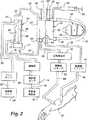
第1図は本発明が組み込まれた透析機械の斜視図である。
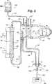
第2図は第1図に示した透析機械による患者を治療する間に提供される透析器、透析器を通じての患者からの体外の血液流路および透析器を通じての透析液の流路を例示した一般化された図である。
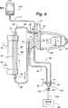
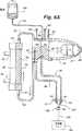
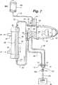
第3図ないし第7図は第2図に示した体外流路を一緒に画成する血液チューブセットと接続された透析器を一般的に例示し、第3図ないし第7図の各々は第1図に示した透析機械を患者に使用するために準備するプライミングおよび再循環プロセスの内部の異なる段階を示す。
第8図は動脈血用管および静脈血用管を第1図に示した透析機械の老廃物ポートと接続する本発明のコネクタの一般化された断面図である。
詳細な説明
本発明を有利に使用できる透析機械の一例を第1図に符号30で示してある。透析機械30は囲い32を含み、該囲いには、または該囲いの内部には、第2図に一般的に例示した透析機械30のこれらの機能的な装置および構成部分が取り付けられ、または収容されている。囲い32は、また、透析機械30、例えば、第1図に示したタッチ・スクリーン・モニタ33を制御するための慣用の入力/出力(“I/O”)装置を含む。
透析機械30は患者36からの血液の流れを制御する少なくとも一つの血液ポンプ34を含む。動脈血用管またはチューブ38は、動脈血クランプ40を通じて血液処理カートリッジ42と接続されている。血液処理カートリッジ42は、通常、使用されるときに、透析機械30のドア44(第1図)の後側に保持され、従って、血液処理カートリッジ42は第1図に示していない。血液ポンプ34もまた、カートリッジ42と隣接したドア44の後側に配置されている。透析機械30の血液ポンプ34は、典型的には、蠕動ポンプである。
動脈血クランプ40が開いているときに、患者36からの血液は体外回路を通じて流れかつ血液ポンプ34が患者36からの血液を吸入する。血液は動脈血用管38を通過しかつカートリッジ42の動脈血溜め46に流入する。血液ポンプ34は、動脈血溜め46から蠕動ポンプの典型的な方法で固定導液管50に対して回転するロータ49により圧入されるポンプヘッダ48を通じての血液を吸入する。ロータ49の前方において回転するポンプヘッダ48の内部の血液は、ポンプヘッダ48を通じてカートリッジ42のマニホルド51の中に推進される。チューブ52はカートリッジ42のマニホルド51からの血液を慣用の透析器54の血液入口53の中に導く。微孔性の膜またはその他の型式の透析媒体56が透析器54の内部を血液室58と透析液室60に分割している。
患者の血液が透析器54を通過するときに、血液の内部の老廃物が膜56を通過し、膜56において、老廃物が透析室60内の透析液と混合する。その後、浄化された液体が血液出口61を通じて透析器54から流出し、その後、チューブ62を通じてカートリッジ42の静脈血溜め64の入口63に移送される。血液の中に故意でなく導入されたいかなる空気も血液が静脈血溜め64内に滞在する間に収集されかつ除去される。
血液は出口65を通じて静脈血溜め64から流出しかつカートリッジ42から静脈血チューブまたは管66を通じて移送される。第2図には示していないが、血液が患者36に戻ることを助けるために、動脈血液ポンプ34と類似した静脈血液ポンプを静脈血用管66に沿って配置することができる。もしも静脈血ポンプが使用されれば、第1図に示すように第2ドア68の後方に配置される。
血液は静脈血溜め64から流出した後に静脈血用管66を通じて空気検出器70に流れる。空気検出器70は、もしも空気が静脈血用管66内に残っていれば、空気の量に関する信号を発生する。もしも過度の空気または危険な量の空気が存在すれば、静脈血用管クランプ72が直ちに閉じかつ検出された空気が患者36に達する前に血液ポンプ34が静脈血用管66を通じての血液の流れを遮断するために停止する。
透析機械30の囲い32もまた、第2図に省略した形態で示した透析液の流路の種々の要素を収容している。透析液流路の要素は、いくつかの種々の弁(その大部分は示さず)と、容器からまたは透析機械30が適切な薬品および浄水源から準備した透析液の内部供給源(internal supply)76から透析液を吸引する透析液ポンプ74とを含む。
透析液ポンプ74は、透析液内部供給源76からの透析液を吸引しかつ透析液を透析液供給チューブまたは管78を通じて透析器54の透析液室60の入口79に送出する。透析液は媒体(medium)56を通過して流れ、媒体56において、透析液が血液室58内の血液から老廃物を吸収する。血液に移送されることが望ましい透析液の内部のいかなる有益な成分も媒体56を通過しかつ血液室58内の血液に入る。
老廃物を含む透析液は、出口81を通じて透析液室60から流出しかつ透析器54からドレンポンプ84の作動により透析液用チューブまたは管82を通じて除去される。透析液からの成分を透析器54の内部の流体移送により血液中に移送することが所望されるときには、ドレンポンプ84は、透析液ポンプ74の容積的なポンプ送出流量と比較してより少ない容積的なポンプ送出流量において作動させることができる。流体搬送により血液から流体成分を取り除くことが望まれる時、ドレンポンプ84は、透析液ポンプ74の体積ポンプ送出流量に比してより大きい体積ポンプ送出流量において作動される。これらの流量制御技術の両方は、限外濾過として知られかつよく知られた透析処理である。
透析器54から除去される透析液は、老廃物用管82を通じて老廃物ドレン86に送出される。老廃物ドレン86は、使用された透析液および蓄積した老廃物を受け入れる別個の容器であってもよいし、または単に公共下水設備に至るドレンであってもよい。透析液の流路を制御する種々の弁およびポンプは、一般的に、透析液液圧装置(dialysate hydraulics)と呼ばれている。
体外流路内の血液は凝固する傾向があるので、抗凝血薬、例えば、ヘパリンを注入するのが一般的である。抗凝血薬を注入する典型的なアプローチは、抗凝血薬を注射器89からゆっくりと送出することである。注射器のプランジャ90は、典型的には、血液凝固阻止ポンプと呼ばれている線形駆動機構(図示せず)により注射器89の中にゆっくりと制御可能に移動される。注射器89からの抗凝血薬は、第2図に示した注射器と連結されたチューブ92を通じてカートリッジ42のマニホルド51の中に導入される。血液凝固阻止ポンプは、所定時間中に血液凝固阻止ポンプがプランジャ90を注射器89の中に移動する程度により透析治療の間に抗凝血薬の所望量を送り出すために制御される。
チューブ94および96は、第2図に示すように、カートリッジ42の動脈血溜め46および静脈血溜め64にそれぞれ接続されている。クランプまたはキャップ(図示せず)が動脈血溜め46および静脈血溜め64から蓄積された空気を選択的に排出するためにチューブ94および96の端部に接続されている。塩水チューブ98もまた、動脈血溜め46と接続され、それにより塩水を低血圧の治療をうけている間に患者に直接に投与することができる。慣用の塩水バッグを支持するための柱100が第1図に示すように囲い32の側に取り付けられている。そのうえ、薬剤またはその他の添加剤を治療の間にアクセスチューブ94を通じて血液中に導入することができる。
血液処理カートリッジ42の動脈血溜め46および静脈血溜め64およびマニホルド51は、チューブ38、48、52、62および66と一緒に、血液チューブセット(“BTS”)と集合的に呼ばれている。このBTSは使い捨てでありかつ典型的には、各々の透析治療後に放棄される。同様に、透析器54は、個個の患者に再使用される透析器として使用されることがまれではないが、使い捨て製品である。透析器は、典型的には、透析治療のために同じクリニックに定期的に訪れる患者により再使用することができる。各々の治療後に、透析器は殺菌剤で浄化され、その後、患者のそのクリニックへの次の訪問まで保管される。その後、透析器は、次の透析治療の間に殺菌剤が患者の血液の流れに移送されないことを保証するために使用前に徹底的に浄化されなければならない。
各々の治療前に、使い捨てのBTSおよび透析器54(透析器が新しいかまたは「使用済み」であるか否かとは関係なく)が透析機械30に取り付けられなければならずかつオペレータにより患者に使用するために準備されなければならない。使い捨てのBTSが殺菌されており、従って、浄化する必要がない場合には、体外回路から空気を除去するために、BTSおよび透析器が殺菌した塩水でプライミングしなければならない。プライミングの間に、透析器54を塩水でフラッシュすることに加えて、透析器の内部の殺菌剤またはその他の化学的な堆積物の実質的にすべてが除去されることを保証するために、塩水を透析器を通じて所定時間の間、再循環させなければならない。この再循環プロセスは、また、体外回路の内部に安定した流れを確保しかつ患者が透析機械30と接続される前に回路の内部に残存しているいかなる空気も除去されることを保証する。プライミングおよび再循環プロセスがいったん完了しかつ回路が塩水で満たされると、動脈血管38が患者に取り付けられかつ患者の血液が回路を通じて吸引される。使用済みの塩水を廃棄するために、静脈血用管66が老廃物ドレン86と接続されかつ患者の血液が回路の内部のすべての塩水を排除した位置で、静脈血用管66が第2図に示すように患者と接続される。
本発明の自動的な性質のために、透析機械のオペレータが上記のプライミングおよび再循環手順の両方を行うために透析機械30に指令する前にBTSおよび透析器54を透析機械30に取り付けかつBTSとの小数のその他の接続を行うことができる。再循環手順を終了したときに、透析機械30がそれ自体を定常状態モードに保ちかつ透析機械を患者と接続する準備が完了したことを指示する。
本発明は、透析機械の自動機能性を得るために、上記の透析機械およびBTSの既知の要素を新しい構成部品と一緒に利用する。先ず、BTSは、第3図に示すように、Y字形またはT字形のコネクタ102(第8図)を含む。コネクタ102は、通例、動脈血用管38および静脈血用管66の端部を老廃物用管104と接続するようになっており、また老廃物用管104は老廃物溜めまたは老廃物ドレン86と接続されている。老廃物用管104は透析器54の出口から延在している老廃物用管82とは別体であると考えられている、とはいえ、当業者は両方の目的のために単一の老廃物用管を利用することができよう。第二に、老廃物用弁106は、老廃物用管104を選択的に開閉するために使用される。弁106が開いているときに、Y字形コネクタ102の内部の流体が老廃物用ドレン86に導かれる。しかしながら、弁106は、動脈血クランプ40および静脈血クランプ72が開いているときに、動脈血用管38を静脈血用管66とY字形コネクタ102を通じて効果的に接続するために閉じることができる。
好ましい代替実施例(第8図)においては、コネクタ102を老廃物ドレン86と接続するために外部老廃物処理口107を使用することができるように、老廃物用弁106を透析機械30の内部に設けることができる。透析機械に使用するためのこのような老廃物処理口の詳細は、「透析ユニットのプライミング」と題しかつ本発明の譲受人に譲渡された米国特許第5041215号明細書において見いだすことができる。老廃物処理口107が第8図に示すように使用されるときに、Y字形コネクタ102のおす部分112が老廃物処理口107の内部に直接に挿入される。老廃物用管104が老廃物処理口107の底端部と接続されかつ透析機械30の囲い32の内部の老廃物用弁106(第8図に示さず)を通じて延在する。老廃物処理口107がコネクタ102のおす部分112と老廃物用管104との間に比較的に大きい間隙114を画成し、それによりY字形コネクタ102と老廃物用管104の内部の流体との間に殺菌された「空気バリヤー」を提供することが好ましい。Y字形コネクタ102の残りの二つの端部116および118が動脈血用管38および静脈血用管66のそれぞれと接続するためのおすルーエル(Luer)コネクタを含むことが好ましい。
Y字形コネクタ102が好ましくは第8図に示すように動脈血用管38および静脈血用管66に予め取り付けられ(かつ外部老廃物用弁106が第3図ないし第7図に使用されるときに老廃物用管104に予め取り付けることができるけれども、Y字形コネクタを該コネクタを含まない血液チューブセットに取り付けるために別個に包装することができる。そのうえ、老廃物処理口107および内部老廃物用弁106が第8図に示すように使用されることが好ましいが、本発明の残りの部分を明瞭に記載するために、第3図ないし第7図においては、老廃物用弁106を透析機械の外部に設けられた老廃物用ドレン86と共に例示してある。
オペレータは、プライミングプロセスの開始前に、BTS(Y字形コネクタ102および取り付けられた老廃物用管104を含む)および透析器54を第1図に示した透析機械30に取り付けなければならない。ポンプヘッダ48(第2図)は、ポンプロータ49のまわりに配置されかつチューブ52および62が第3図に示すように透析器54と接続されている。次に、オペレータは、動脈血用管38および静脈血用66をそれらのそれぞれのクランプ40および72に通しかつ老廃物用管104を老廃物用弁106を通じて老廃物ドレン86と接続する。
種々の管を第3図に示すように接続しかつクランプ40および72が閉ざされたことを確認した後に、オペレータは、柱100(第1図)から殺菌した塩水バッグ108を吊しかつバッグ108を留めた後、バッグ108からの管110を動脈血溜め46上の塩水チューブ98と接続しなければならない。その後、オペレータは、動脈血溜め46から延在しているチューブ94のキャップを開き、それにより動脈血溜め46の内部の空気がチューブ94を通じて逃出するときに、バッグ108からの塩水が動脈血溜め46内に重力で満たされる。動脈血溜め46が塩水(第3図)でいったん殆ど満たされると、オペレータは、チューブ94のキャップを閉じる。透析機械30は、今や、プライミングおよび再循環のために設定され、そしてオペレータの唯一残っている作業は、タッチ・スクリーン33(第1図)からの自動プライミングおよび再循環機能を選択することである。
いったん透析機械30が、操作を開始するように指令されると、第4図に示すように、動脈血クランプ40および老廃物用弁106を開き、それにより動脈血溜め46の内部の塩水が老廃物ドレンを通じて廃棄処分される前に動脈血用管38内の空気をフラッシュすることを可能にすることにより、プライミング手順を開始する。動脈血溜め46の内部の塩水がバッグ108の内部の塩水から補給され、かつ透析機械30がバッグ108の内部の殺菌した塩水を保存するための所定時間後に動脈血クランプ40を閉じる。しかしながら、この所定時間は動脈血用管38から空気を除去するために十分である。
透析機械30は、動脈血クランプ40を閉じかつ静脈血クランプ72を開くことにより、第5図に示すように、自動プライミングプロセスにおける次のステップを直ちに開始する。その後、透析機械は、ポンプロータ49を前進方向に回転して体外回路(BTSおよび透析器54)の残りの部分をバッグ108からの塩水で満たすように指令する。塩水は、静脈血溜め64に流入する前にポンプヘッダ48、マニホルド51、チューブ52、透析器54およびチューブ62を通過する。その後、塩水は静脈溜め64の出口65(第2図)から排出されかつ静脈血用管66を通じて(開いた静脈血クランプ72を越えて)かつY字形コネクタ102を通じて老廃物ドレン86に至る。このステップの間に、追加の塩水が動脈血溜め46の内部の塩水のレベルを維持するためにバッグ108から取り出される。
この回路をこの態様でプライミングすることにより、新しい透析器54を(透析器の製造者により推薦されているように)フラッシュするか、または再使用された透析器からの殺菌剤の大部分を浄化する作用をする。そのうえ、BTSおよび透析器54の内部の多量の空気が塩水(および透析器からフラッシュされた任意の殺菌剤)により駆除され、老廃物ドレンに流される。しかしながら、ある量の空気が透析器54の内部に捕獲され、残存しており、かつこの捕獲された空気が典型的には入口53と隣接した血液室58の頂部に浮遊している。
第6図に示した自動プライミング手順における次のステップは、老廃物用弁106を閉じ、動脈血クランプ40を開き、かつ血液ポンプロータ49を後進方向に運転して、塩水を体外回路を通じて後方に押し流すことである。この流体は、動脈血溜め46からY字形コネクタ102を通じて静脈血溜め64の中に押し流され、そして透析器54を通じて後方に押し流され、それにより静脈血溜め64の内部の空気の一部分が透析器54の頂部に捕獲された空気と一緒に入口53外に押し流されかつマニホルド51の中に流入する。その後、連行した気泡がポンプ34により動脈血溜め46の中に押し込まれ、これらの空気は動脈血溜め46の頂部に集合する。より多量の気泡が動脈血溜め46の中に押し込まれるときに、動脈血溜め46の頂部における増大した量の空気が動脈血溜め46内の塩水のレベルを減らすと共に、同時に追加の塩水が第6A図に示すように塩水チューブ98を通じて動脈血溜め46に流入することを阻止する。
空気がいったんBTSおよび透析器54外に押し出されかつ静脈血溜め64および動脈血溜め46内の流体のレベルが調節されると、透析機械30が透析器、塩水バッグまたはBTSの接続のいずれをも変更することなく、プライミング手順を再循環手順に自動的に切り換える。
再循環手順は、第7図に示すように、老廃物用弁106を閉じ、動脈血クランプ40および静脈血クランプ72を開きかつ血液ポンプ34を前進方向に運転すると共に、透析機械30が透析液の流路のための責任を果たす液圧応用装置に媒体56を横切って透析器54からの所定レベルの流体を吸引するように指令することを必要とする。
再循環プロセスは、本質的には、動脈血用管38および静脈血用管66をそれぞれY字形コネクタ102を通じて接続することにより患者36を短絡する通常の透析プロセスとよく似ている。透析液用の液圧応用装置に透析器54の血液室58からのある量の流体を吸引するように指令することにより、透析機械30が本質的に限外濾過を行っている。しかしながら、媒体56を通じて吸引される液体は、プライミング手順後に透析器54の内部に依然として残存している塩水および任意の殺菌剤のみを含む。従って、再循環プロセスは、再使用された透析器が患者と接続される前に適切に浄化されることを保証する助けをする。
再循環の間に塩水が透析器から吸引されるときに空気が体外回路を満たすことを阻止するために、追加の塩水がバッグ108から動脈血溜め46の中に重力の作用で供給される。再循環プロセスは、また、透析器54またはBTSのいずれかの内部に残るいかなる空気をも収集しかつ静脈血溜め64および動脈血溜め46の両方の頂部における空気を定着(deposit)させることを助ける。その後、これらの静脈血溜め64および動脈血溜め46の内部に収集された空気は、再循環プロセスの終りにチューブ96および94のそれぞれに設けられたクランプ(図示せず)を開くことにより排出することができる。
タッチ・スクリーン・モニタ33(第1図)が再循環のために残存している時間を表示するための秒「分」読みのタイマー(count−down timer)を提供することができる所定時間後に、透析機械30が再循環プロセスが完了したことを(タッチ・スクリーン・モニタ33で指示すると共に)可聴信号でオペレータに通知する。同時に、透析機械は、透析液用の液圧応用装置に対して透析器媒体56を通じて流体を吸引することを停止することを指令しかつポンプが塩水を体外回路を通じて再循環することを継続することを単に可能にする。「限外濾過」プロセスを停止することにより、透析機械30は、透析器から吸引された流体を補給するためにバッグ108から吸引しなければならない塩水を保存する。
体外回路から追加の流体が吸引されないので、透析機械は、患者が透析機械と接続される準備が完了するまで、塩水を回路の内部に再循環し続ける。確立された流れを維持することに加えて、引き続く再循環により、透析器の内部に残存している殺菌剤のいかなる潜在的なポケットをも低下させることを助ける。
従って、オペレータは透析機械30がプライミング手順および再循環手順の両方を終了した時期を知っている。オペレータは、さらに、もしも患者が遅延していれば、透析機械がいったん限外濾過プロセスを停止すると、透析機械が塩水をなんら浪費することなくその有益な再循環機能を継続する。従って、診療所は、プライミングおよび再循環プロセスの各々のステップのために使用される所定時間および流体の量を含むそのパラメータを設定することができ、それにより十分なレベルの塩水が透析治療の間に使用するためにバッグ108の内部に残っている。前述したように、患者の治療の間に、塩水バッグ108が動脈血溜め46の塩水チューブ98に取り付けられたままになっている。塩水管110が透析治療の間に通常クランプで締め付けられているとはいえ、塩水管110は、患者が低血圧になりかつ流体の流入(influx)を必要とする場合には、開くことができる。
プライミングおよび再循環手順がいったん完了すると、オペレータは、管94および110をクランプで締め付けかつ動脈血溜め38をY字形コネクタ102から分離しさえすればよい。動脈血用管38がいったん分離されると、BTSの内部の塩水がY字形コネクタ102からこぼれることを阻止するために、Y字形コネクタ102の革ひも等でつながれたキャップ120が端部116上に配置される。その後、動脈血用管38が第2図に示すように患者36に取り付けられる。患者の血液が体外回路の内部の塩水と置換されるときに、再循環した塩水を廃棄処分するために静脈血用管66がY字形コネクタ102を通じて廃棄物ドレン86と接続された状態になっている。患者の血液がいったん静脈血用管66の端部に達すると、静脈血用管66がY字形コネクタ102の端部118から分離されかつ患者に第2図に示すように取り付けられる。その後、使い捨てのY字形コネクタ102が廃棄される。従って、透析治療がこの時点から通常の方法で進められる。
前述したように、第4図ないし第7図に示すような自動プライミングおよび再循環プロセスの種々のステップにおいては、種々のクランプを特定の所定の時期に開閉しかつポンプロータ49を所定時間の間に種々の方向にかつ種々の速度で作動させることが必要である。囲い32の内部のマイクロプロセッサ(図示せず)がプライミング手順および再循環手順の両方を行うために上記のようなクランプおよびポンプを作動させるためにプログラムされている。従って、透析装置30を使用する種々の病院および診療所は、病院または診療所により予め確立されたパラメータの特定の組により種々の所定の時期および時間(およびそれらの対応した流体の流量)においてマイクロプロセッサをプログラムしさえすればよい。一例として、かつこの例に限定するものではないが、第4図に示した自動プライミングおよび再循環プロセスのステップの間には、透析機械30は、動脈血用管38を動脈血溜め46内に保管された塩水でフラッシュするために動脈血クランプ40を7秒間開くためにプログラムすることができる。診療所は動脈血用管38から空気を完全にフラッシュするために7秒の期間で十分でありかつクランプ40をさらに長い期間開けると殺菌した塩水を浪費するだけであることを予め決定しているかもしれない。同様に、診療所は、典型的には、透析液用の液圧応用装置が透析器媒体を通じて(例えば、20分間)流体を吸引することを停止するように指令されるまで、血液ポンプ34が第7図に示した再循環ステップにおいて作動する時間量に対するパラメータを確立することになろう。別の態様では、種々のステップの長さを透析器の異なる型式により変更することができる。これらの所定の時間(および使用される塩水の対応した所定量)は、十分な時間および塩水が所望の効果を得ることが可能であることと、過度に長い時間の間ステップを延長することにより時間および塩水の両方を浪費することを阻止することとの両方を保証するために診療所により確立されてきた。
そのうえ、特定のステップに関する変更を変数の変更を考慮して透析機械30にプログラムすることができる。例えば、前述したように、新しい透析器が使用されるときに、透析器54(第5図)を含む回路の静脈血側をプライミングするステップを変更することができる。透析器製造者は、典型的には、新しい透析器の場合には、再使用されつつある透析器よりも長い期間の間塩水でフラッシュすることが必要であるとしている。従って、透析機械30が新しい透析器が使用されることを知らされたときには、該機械は製造者の要求条件を満たすために第5図に示したステップを延長することができる。同様に、もしもプレート式透析器が第1図ないし第7図に例示したより多数の典型的な中空繊維式透析器の代わりに利用されるとすれば、透析器製造者は、典型的には、(風船を膨らませると同様に)透析器の内部のプレートを膨脹させるために、プライミングの間に、透析器に高い圧力の流れを作用させることを提案している。もしも透析機械30がプレート式透析器が使用されることを知らされれば、該機械は静脈血クランプ72をより長い時間の間閉ざしかつ静脈血クランプ72を開く前に、透析器の内部の圧力をより高く上昇させることにより静脈血溜め64内の流体のレベルをリセットする上記のステップを変更することができる。
従って、本発明の有意な貢献は、診療所または病院が透析機械を組み立てるための確立されたパラメータが人間の誤りまたは混乱または注意散漫をひき起こすことなく正確に遵守されることを確信していることである。また、透析機械30は種々の不測の事態、例えば、種々の型式の透析器を使用することをプログラムすることができる。しかしながら、本発明の最も大きい利益は、透析機械がプライミングおよび再循環手順の種々のステップを通じて自動的に循環する間に忙しい看護婦または透析オペレータが別の職務に留意する自由が得られることである。オペレータは、もはや透析機械の組立、調整の過程に透析機械に再訪しかつ血液チューブセットの構成を変更する必要がない。むしろ、オペレータは、前記手順を開始する前に限られた数の接続を行うことのみが必要であり、その後、透析機械にすべての潜在的な可変のパラメータ(すなわち、使用される透析器の型式)を知らせた後に、透析機械に前記手順を開始するように指令する。そのときに、オペレータは、その注意をその他の患者または組立または調整を必要とするその他の機械に向けることができ、透析機械が予め確立されたパラメータによりプライミングおよび再循環手順を完了しかつオペレータに透析機械が患者と接続されるべき時期を通知することを認知しているので好適である。多数の機械が据え付けられかつ調整しなければならない診察所の据付けにおいては、本発明はオペレータの多大な時間を節減することができると共に、同時に各々の機械が診察所の確立したパラメータと首尾一貫した態様で据え付けられることが保証される。本発明と付随した労力の節減は、プライミングおよび再循環手順の間に最適な量の塩水を使用することから得られる節減と共に、病院および透析診察所にとって顕著な金銭的な節減が得られる。
本発明の教旨は、透析機械をプライミングしかつ再循環する新規の方法と、透析機械がこの新規の方法を実施することができる独特の装置との両方に関する。この装置は、老廃物用弁106(透析機械に従来使用されていない)と、Y字形コネクタ102(慣用の血液チューブセットに従来に含まれていない)とを含む。そのうえ、本発明の好ましい一実施例は2本の針を使用する透析治療(すなわち、第2図に示すように、二つの別の位置において患者から血液を吸引しかつ血液を戻すために単一のポンプ34を使用すること)により例示してあるが、当業者は同じ技術を患者の単一の位置から血液を吸引しかつ血液を戻す両方のために2つの別個の血液ポンプを利用する透析機械(すなわち、「単一の針および2つのポンプ」を使用する機械)に適用することができよう。前述したように、ドア68の後方の囲い32の面上に第2血液ポンプ(図示せず)を設けるように準備がなされる。そのうえ、本発明の現在好ましい実施例においては、透析オペレータが当初空気管94(第3図)のクランプを緩めかつクランプを締め付けることにより動脈血溜めに充填することを要求しているが、当業者は第4図ないし第7図に示した残りのステップと同様なプライミングおよび再循環プロセスにおけるこのステップを自動化することが可能であろう。
本発明は、透析機械が動脈血クランプ(ある単一のポンプを含む透析機械に一般的であるような)を既に含んでいなければ、透析機械が動脈血クランプ40に加えて老廃物用弁106(と血液ポンプおよび弁を制御するための適切なマイクロプロセッサソフトウェア)がいったん取り付けられれば、既存の透析機械により実施することができる。そのうえ、慣用の血液チューブセットは、Y字形コネクタ102を含むために変更されなければならない。従って、本発明は上記の装置を含む新しい透析機械および既存の透析機械の両方により実施することができる。
以上、本発明の現在好ましい実施例およびその多くの改良について特に詳細に記載した。この説明は本発明を実施する好ましい一例であるが、必ずしも本発明の範囲をこの例に限定することを意図していない。本発明の範囲は次の特許請求の範囲により定義されている。The present invention relates to a new and improved dialysis apparatus and technique for automatically priming and recirculating fluid with a dialyzer and a disposable blood tube set for connecting a patient to a dialysis machine.
Background of the Invention
Dialysis machines are used as an alternative to the natural kidney function of the human body. This dialysis device acts to remove the natural accumulation of human waste from the blood by separating the waste from the blood. The separated waste is discarded and the purified blood is returned to the human body.
This dialysis machine consists of a dialysis machine, a dialyzer, a disposable blood tube set and a supply of chemicals to produce a dialysate solution used inside the dialyzer.
This dialyzer is used with a dialysis machine to separate waste products from blood. The dialyzer includes a microporous membrane disposed within a closed housing, which effectively separates the housing into a blood compartment and a dialysate compartment or a filtrate compartment. Blood removed from the patient flows through the blood side of the disposable blood tubing set and dialyzer. A dialysate solution prepared from chemicals passes through the dialysate side of the dialyzer. Waste from blood flows through the membrane into the dialysate by osmosis, ionic transfer or fluid transport, and the type of dialysis treatment opposes the desired components from the dialysate Can flow into the blood through the membrane in the direction. The transfer of the waste product into the dialysate allows the desired components from the dialysate to flow into the blood stream and cleans the blood.
Blood transfer between the patient and the dialyzer takes place inside a disposable blood tube set. The blood tube set and dialyzer constitute a closed extracorporeal passage through which the patient's blood travels. The blood tube set includes an arterial blood tube connected to an arterial reservoir to draw blood from the patient, a venous blood tube connected to a venous reservoir to return blood to the patient, a pump and a dialyzer. And several other tubes for connection between the reservoir and the venous blood reservoir. Before the blood tubing set and dialyzer can be used for dialysis therapy, both instruments must be primed with sterile saline to remove air from the extracorporeal circuit. Once priming is complete, the saline is recirculated through the blood tubing set and dialyzer to generate a steady flow and remove additional trapped air from inside the extracorporeal circuit. This priming and recirculation process also acts to flush the dialysis membrane to clean the dialyzer and remove any deposits or chemicals left over from previous use.
If the patient reuses the same dialyzer for subsequent dialysis treatment, the dialyzer must be cleaned with a disinfectant or sterilized solution. However, the disinfectant itself must be removed from the dialyzer prior to each dialysis treatment. Such a cleaning procedure is effectively performed when the dialyzer undergoes the priming and recirculation process described above. During priming, the dialyzer is flushed with brine. Brine removes most of the fungicide. Moreover, during the brine recirculation, the dialysis machine can be commanded to remove a predetermined stream of brine directly from the dialyzer. This predetermined flow corresponds to the removal of a predetermined amount of fluid (or weight) from the patient during dialysis ("pulling off") and is generally "ultrafiltration". )is called. Therefore, by removing the salt water by ultrafiltration during recirculation of the salt water, the germicide remaining inside the dialyzer can be removed when the germicide mixes with the salt water. Brine removed by ultrafiltration is replenished from a brine source connected to the extracorporeal circuit so that no additional air is added to the extracorporeal circuit during recirculation.
In current dialysis machines, it is necessary that the priming step and the recirculation step be performed separately, and further, when the priming step is completed and before the recirculation step is started, the operator can It is necessary to change. For example, a typical priming sequence in a conventional dialysis machine is where the operator connects the dialysis machine outlet (ie, the venous blood tubing) to a saline source and then reverses the dialysis machine to fill the extracorporeal circuit with saline. It is necessary to drive to. Initially, the priming solution flows through the dialyzer and out of the extracorporeal circuit through the inlet tube (ie, the arterial blood tube) of the dialysis machine in light of the backflow. The operator connects the arterial blood tubing with a waste reservoir or waste drain to discard the priming solution. The initial priming solution is discarded because it can contain a relatively large amount of disinfectant that has been flushed from the dialyzer when the dialyzer is sterilized and reused after the previous dialysis treatment.
Once the priming of the blood tube set and dialyzer is complete, the operator separates the venous and arterial blood tubes of the blood tube set from the salt water source and the waste reservoir, respectively, and then the venous and arterial blood tubes. Are connected together (ie, the patient is shorted). The operator then switches the dialysis machine from the reverse operation and operates the dialysis machine in the normal manner to recirculate the saline through the extracorporeal circuit. The operator can also connect a salt water source to a different part of the circuit, thereby supplying additional salt water instead of salt water removed by ultrafiltration during recirculation.
Thus, the priming and recirculation process of conventional dialysis machines requires considerable attention from trained operators. The operator must change the configuration of the dialysis machine at several points during the process. Therefore, if the operator is confused after initiating the priming procedure and cannot reconfigure the tube set and immediately return to the dialysis machine to initiate the recirculation procedure, the next patient A considerable delay time may occur to prepare the dialysis machine for The potential for delay is when the operator or nurse has to adjust several different dialysis machines in the course of the day in adjusting the machine at the hospital or clinic and the operator is quite confused and frustrated Increase considerably.
In addition, the assembly and adjustment of the machine due to the often confused or lazy atmosphere of the hospital or clinic when a skilled nurse or technician is not likely to make a mistake during the assembly or adjustment of the dialysis machine Occasionally an opportunity to make mistakes increases. For example, an operator can become confused while the dialysis machine is recirculating and removing salt water from the dialyzer. If the salt water source (eg, salt water source) dries while the operator is confused, the dialysis machine tends to continue to draw salt water through the dialyzer and empty the salt water in the extracorporeal circuit, thereby Air may enter the extracorporeal circuit. Once a significant amount of air is introduced into the extracorporeal circuit, the priming and recirculation process must be initiated at the expense of dialysis machine downtime and sterilized saline. In addition, although hospitals and dialysis clinics typically establish specific parameters for assembling, adjusting, and using dialysis machines, these specific parameters can be used to assemble a specific dialysis machine or When adjusting, it may not be observed by the operator. For example, when an operator is confused during the process of assembling or adjusting a dialysis machine, or when a hospital or clinic employs a new operator who is not familiar with established assembly or adjustment parameters Inconsistent priming or recirculation procedures can occur (eg, if the amount of saline is too low during priming or if the dialysis machine is run for a very short time during recirculation).
An example of a prior art device for purging a blood tube set and purging air from the blood tube set is described in WO-A-08 / 06460, which describes a blood tube set for use with a platelet separator / plasma filtration device. Provided in the description. Several pumps and clamps are placed along the blood tube set to assist in the priming and purging procedure, while a sterilized enclosure holds the collection and return needles of the blood tube set during the priming and purging procedure. This sterilized enclosure provides fluid communication between the collection needle and the return needle, thus providing continuous circulation through the blood tube set.
These considerations and other considerations have contributed to devise the invention summarized below.
Summary of invention
One important aspect of the present invention is that the dialysis machine operator does not need to change the configuration of the dialysis machine during the separate steps of priming and recirculation, and the sterilized fluid is primed through the dialysis machine extracorporeal circuit. And new ways of recycling. Another important aspect of the present invention is that the operator of the dialysis machine can perform other operations while the dialysis machine automatically primes and recirculates the sterilized fluid through the extracorporeal circuit before connecting the dialysis machine to the patient. It is to be able to engage in duties freely. Yet another important aspect of the present invention is to prime a dialysis machine that adheres to specific priming and recirculation parameters established by a hospital or clinic and does not cause human error after the priming and recirculation process is initiated And providing a method of recirculation. Yet another important aspect of the present invention relates to storing a sterilized solution that is used to prime an extracorporeal circuit and is recycled through the circuit after the extracorporeal circuit is initially primed.
According to these and other aspects, the present invention provides a blood pump, a dialyzer, an arterial blood tube for aspirating blood from a patient, an arterial blood reservoir for receiving blood received from the patient, and a dialyzer Method for assembling and adjusting a dialysis machine having a venous reservoir for containing blood pumped from an arterial reservoir through and a blood tube set including a venous blood tube for returning blood from the venous reservoir to the patient As a general summary. The dialysis machine encompassing the present invention further includes a connector adapted to connect the arterial and venous blood tubing with a waste tubing leading to the waste drain and a waste between the connector and the waste drain. A waste valve disposed along the material pipe. This connector is preferably an element of a disposable blood tube set.
The waste valve drains fluid from either the arterial blood tube or the venous blood tube (when the waste valve is open) and the arterial blood (when the waste valve is closed) The fluid between the working tube and the venous blood tube can be selectively opened and closed for transport through the connector. By selectively actuating blood pumps and waste valves in addition to clamps attached to both arterial and venous blood tubes, the dialysis machine can be primed and re-started without the assistance of the dialysis machine operator. Both circulation procedures can be completed automatically. Prior to instructing the dialysis machine to initiate the priming and recirculation process, the operator connects a sterile fluid source (eg, a saline bag) with the blood tubing set and arterial and venous blood tubing through the connector. It is necessary to connect to the waste pipe.
The process of priming and recirculating fluid through the extracorporeal circuit consists of the following steps: closing the arterial blood clamp of the arterial blood tube to prevent the fluid from filling the arterial blood tube and filling the arterial reservoir with a sterilized solution. Open the arterial blood clamp and waste valve, fill the arterial blood tube with sterilized solution from the arterial blood reservoir, and pass a certain amount of sterilized solution inside the arterial blood tube through the connector and open the waste valve Then drain the waste drain down, close the arterial blood clamp to store the sterilized solution inside the arterial blood tube, open the venous blood clamp on the venous blood tube and drive the pump forward Aspirate the sterilized solution from the arterial reservoir through the dialyzer and venous reservoir and open the sterilized solution through the venous blood tubing and connector and open Pass through the waste valve and drain downward from the waste drain, close the waste valve, open the arterial blood clamp and drive the pump backwards to pass the sterilized solution back through the dialyzer and blood tubing set Preferably, the method includes circulating and thereby removing air from the dialyzer and operating the pump in the forward direction to recirculate the sterilized solution through the dialyzer and blood tubing set.
Additional steps can be added to the basic sequence of steps described above. For example, fluid can be drawn directly from the dialyzer while the sterilized solution is recirculated through the dialyzer and blood tube set.
The above steps are preferably controlled automatically by the dialysis machine, although one or more of the initial steps can be performed manually by the dialysis machine operator, It is still within the scope of the present invention. Substantially automatic control of both the priming and recirculation processes allows the dialysis machine operator to engage freely in other duties and reduces the possibility of operator error. Moreover, the automatic nature of the assembly and adjustment process provides a consistently prepared dialysis machine and typically utilizes less sterilized solution than manual priming and recirculation procedures.
A more complete appreciation of the present invention and its scope can be obtained from the accompanying drawings briefly summarized below, the following detailed description of the presently preferred embodiments of the invention, and the appended claims.
[Brief description of the drawings]
FIG. 1 is a perspective view of a dialysis machine incorporating the present invention.
FIG. 2 illustrates the dialyzer provided during treatment of the patient by the dialysis machine shown in FIG. 1, the extracorporeal blood flow path from the patient through the dialyzer, and the dialysate flow path through the dialyzer. It is the generalized figure.
FIGS. 3-7 generally illustrate a dialyzer connected to a blood tube set that together define the extracorporeal flow path shown in FIG. 2, each of FIGS. Figure 2 shows the different stages within the priming and recirculation process of preparing the dialysis machine shown in Figure 1 for use on a patient.
FIG. 8 is a generalized cross-sectional view of the connector of the present invention that connects the arterial and venous blood tubes with the waste port of the dialysis machine shown in FIG.
Detailed description
An example of a dialysis machine in which the present invention can be advantageously used is indicated by
When
As the patient's blood passes through the
Blood exits the
The blood flows out from the
The
The
The dialysate containing waste products flows out of the
The dialysate removed from the
Since blood in the extracorporeal channel tends to clot, it is common to inject an anticoagulant such as heparin. A typical approach to injecting an anticoagulant is to slowly deliver the anticoagulant from a
The
The
Before each treatment, a disposable BTS and dialyzer 54 (regardless of whether the dialyzer is new or “used”) must be attached to the
Because of the automatic nature of the present invention, the BTS and
The present invention utilizes the above-described dialysis machine and known elements of the BTS along with new components to obtain the automatic functionality of the dialysis machine. First, as shown in FIG. 3, the BTS includes a Y-shaped or T-shaped connector 102 (FIG. 8).
In a preferred alternative embodiment (FIG. 8), the
Y-shaped
The operator must attach the BTS (including the
After connecting the various tubes as shown in FIG. 3 and confirming that the
Once the
By priming this circuit in this manner, the
The next step in the automatic priming procedure shown in FIG. 6 is to close the
Once air is pushed out of the BTS and
As shown in FIG. 7, the recirculation procedure closes the
The recirculation process is essentially similar to the normal dialysis process where the
To prevent air from filling the extracorporeal circuit as saline is drawn from the dialyzer during recirculation, additional saline is supplied from the
After a predetermined time, the touch screen monitor 33 (FIG. 1) can provide a count-down timer to display the remaining time for recirculation. The
As no additional fluid is aspirated from the extracorporeal circuit, the dialysis machine continues to recirculate saline water into the circuit until the patient is ready to connect with the dialysis machine. In addition to maintaining an established flow, subsequent recirculation helps to reduce any potential pockets of disinfectant remaining inside the dialyzer.
Thus, the operator knows when the
Once the priming and recirculation procedure is complete, the operator need only clamp the
As described above, in the various steps of the automatic priming and recirculation process as shown in FIGS. 4-7, various clamps are opened and closed at specific predetermined times and the
In addition, changes for specific steps can be programmed into the
Thus, the significant contribution of the present invention is convinced that clinics or hospitals can accurately observe established parameters for assembling dialysis machines without causing human error or confusion or distraction That is. The
The teachings of the present invention relate both to a new method of priming and recirculating a dialysis machine and a unique device that allows the dialysis machine to implement this new method. The device includes a waste valve 106 (not conventionally used in dialysis machines) and a Y-connector 102 (not conventionally included in conventional blood tubing sets). In addition, a preferred embodiment of the present invention is a dialysis treatment that uses two needles (ie, as shown in FIG. 2, a single unit for aspirating and returning blood from a patient at two different locations. Dialysis utilizing two separate blood pumps for both aspirating blood and returning blood from a single location on the patient. It could be applied to a machine (ie a machine using a “single needle and two pumps”). As described above, provisions are made to provide a second blood pump (not shown) on the face of the
If the dialysis machine already does not include an arterial blood clamp (as is common with dialysis machines including a single pump), the dialysis machine may add waste valve 106 (in addition to arterial blood clamp 40). Once installed, appropriate microprocessor software for controlling blood pumps and valves can be implemented with existing dialysis machines. Moreover, conventional blood tube sets must be modified to include a Y-shaped
The presently preferred embodiment of the invention and many of its improvements have been described in particular detail above. This description is a preferred example of implementing the invention, but is not necessarily intended to limit the scope of the invention to this example. The scope of the present invention is defined by the following claims.
Claims (14)
Translated fromJapanese動脈血用管(38)および静脈血用管(66)をコネクタ(102)の2つのアームと接続し、
コネクタ(102)の第3アームを老廃物ドレン(86)と接続し、
老廃物用弁(106)をコネクタ(102)の第3アームと老廃物ドレン(86)との間に接続し、
流体が動脈血用管(38)を満たすことを阻止するために動脈血用管(38)の動脈血クランプ(40)を閉じ、
動脈血溜め(46)を殺菌した溶液で満たし、
動脈血クランプ(40)および老廃物用弁(106)を開いて、動脈血用管(38)を動脈血溜め(46)からの殺菌した溶液で満たしかつ動脈血用管(38)の内部の殺菌した溶液をコネクタ(102)を通じかつ開いた老廃物用弁(106)を通過して老廃物ドレン(86)の下方で排出し、
動脈血クランプ(40)を閉じ、
静脈血用管(66)の静脈血クランプ(72)を開きかつポンプ(34)を前進方向に運転して、動脈溜め(46)からの殺菌した溶液を透析器(54)および静脈血溜め(64)を通じて吸引しかつ殺菌した溶液を静脈血用管(66)およびコネクタ(102)を通じかつ開いた老廃物用弁(106)を通過して老廃物ドレン(86)の下方で排出し、
老廃物用弁(106)を閉じ、動脈血クランプ(40)を開きかつポンプ(34)を後進方向に運転して,殺菌した溶液を透析器(54)および血液チューブセットを通じて後方に吸引しかつ
ポンプ(34)を前進方向に運転して、殺菌した溶液を透析器(54)および血液チューブセットを通じて再循環させるステップを含む方法。From a pump (34), a dialyzer (54), an arterial blood tube (38) for drawing blood from the patient, an arterial blood reservoir (46) for containing blood received from the patient, and an arterial blood reservoir (46) A venous blood reservoir (64) for containing blood pumped through the dialyzer (54), a venous blood tube (66) for returning blood from the venous blood reservoir (64) to the patient, and an arterial blood tube And dialysis machine (30) having a blood tube set including a connector (102) for connecting a venous blood tube (66), said method comprising arterial blood tube (38) and vein Connecting the blood tubing (66) with the two arms of the connector (102);
Connecting the third arm of the connector (102) to the waste drain (86);
Connecting the waste valve (106) between the third arm of the connector (102) and the waste drain (86);
Closing the arterial blood clamp (40) of the arterial blood tube (38) to prevent fluid from filling the arterial blood tube (38);
Fill the arterial reservoir (46) with a sterilized solution;
Open the arterial blood clamp (40) and waste valve (106) to fill the arterial blood tube (38) with the sterilized solution from the arterial blood reservoir (46) and fill the sterilized solution inside the arterial blood tube (38). Discharging through the connector (102) and through the open waste valve (106) below the waste drain (86);
Close the arterial blood clamp (40),
The venous blood clamp (72) of the venous blood tube (66) is opened and the pump (34) is operated in the forward direction so that the sterilized solution from the arterial reservoir (46) is removed from the dialyzer (54) and the venous blood reservoir ( 64) and draining the sterilized solution through the venous blood tubing (66) and connector (102) and through the open waste valve (106) below the waste drain (86);
The waste valve (106) is closed, the arterial blood clamp (40) is opened and the pump (34) is driven in the reverse direction to aspirate and pump the sterilized solution back through the dialyzer (54) and blood tubing set. Driving (34) in the forward direction to recirculate the sterilized solution through the dialyzer (54) and blood tubing set.
動脈血溜め(46)を殺菌した溶液で満たすステップに続くステップが透析機械(30)により自動的に行われる請求の範囲第1項に記載の方法。The dialysis machine (30) includes a microprocessor adapted to automatically actuate the pump (34), the arterial blood clamp (40), the venous blood clamp (72) and the waste valve (106), and an arterial reservoir ( The method of claim 1 wherein the step following the step of filling 46) with the sterilized solution is performed automatically by the dialysis machine (30).
老廃物用弁(106)をコネクタ(102)の第3アームと老廃物ドレン(86)との間に接続するステップに続くステップが透析機械(30)により自動的に行われる請求の範囲第1項に記載の方法。The dialysis machine (30) includes a microprocessor adapted to automatically actuate the pump (34), arterial blood clamp (40), venous blood clamp (72) and waste valve (106), and for waste The step according to claim 1, wherein the step following the step of connecting the valve (106) between the third arm of the connector (102) and the waste drain (86) is performed automatically by the dialysis machine (30). the method of.
動脈血溜め(46)を殺菌した溶液で満たすステップに続くステップが透析機械(30)により自動的に行われる請求の範囲第6項に記載の方法。The dialysis machine (30) includes a microprocessor adapted to automatically actuate the pump (34), arterial blood clamp (40), venous blood clamp (72) and waste valve (106), and an arterial blood reservoir ( The method according to claim 6, wherein the step following the step of filling 46) with the sterilized solution is performed automatically by the dialysis machine (30).
動脈血溜め(46)を殺菌した溶液で満たすステップに続くステップが透析機械(30)により自動的に行われる請求の範囲第10項に記載の方法。The dialysis machine (30) includes a microprocessor adapted to automatically actuate the pump (34), the arterial blood clamp (40), the venous blood clamp (72) and the waste valve (106), and an arterial reservoir ( The method according to claim 10, wherein the step following the step of filling 46) with the sterilized solution is performed automatically by the dialysis machine (30).
透析器(54)の内部の流体圧力を増大しかつ透析器(54)の内部のプレートを相互に隔離するために殺菌した溶液を透析器(54)および血液チューブセットを通じて再循環させるステップの間に静脈血クランプ(72)を閉じ、かつ
プレート型透析器(54)の内部のプレートが十分に隔離された後に透析器(54)および血液チューブセットの内部の圧力を等しくするために静脈血クランプ(72)を開くステップを含む請求の範囲第1項に記載の方法。The dialyzer (54) is a plate-type dialyzer having a plurality of plates isolated from each other to define a blood channel and a dialysate channel adjacent thereto; and
During the step of recirculating the sterilized solution through the dialyzer (54) and blood tube set to increase the fluid pressure inside the dialyzer (54) and isolate the plates inside the dialyzer (54) from each other To close the venous blood clamp (72) and equalize the pressure inside the dialyzer (54) and blood tube set after the plate inside the plate dialyzer (54) is sufficiently isolated The method of claim 1 including the step of opening (72).
動脈血溜め(46)を殺菌した溶液で満たすステップに続くステップが透析機械(30)により自動的に行われる請求の範囲第13項に記載の方法。The dialysis machine (30) includes a microprocessor adapted to automatically actuate the pump (34), the arterial blood clamp (40), the venous blood clamp (72) and the waste valve (106), and an arterial reservoir ( 14. The method according to claim 13, wherein the step following the step of filling 46) with the sterilized solution is performed automatically by the dialysis machine (30).
Applications Claiming Priority (3)
| Application Number | Priority Date | Filing Date | Title |
|---|---|---|---|
| US08/481,755US5650071A (en) | 1995-06-07 | 1995-06-07 | Technique for priming and recirculating fluid through a dialysis machine to prepare the machine for use |
| US08/481,755 | 1995-06-07 | ||
| PCT/US1996/009231WO1996040320A1 (en) | 1995-06-07 | 1996-06-06 | Technique for priming and recirculating fluid through a dialysis machine |
Related Child Applications (1)
| Application Number | Title | Priority Date | Filing Date |
|---|---|---|---|
| JP2006333948ADivisionJP4427047B2 (en) | 1995-06-07 | 2006-12-12 | Technology to prime and recirculate fluids with dialysis machines |
Publications (2)
| Publication Number | Publication Date |
|---|---|
| JPH11506962A JPH11506962A (en) | 1999-06-22 |
| JP3951030B2true JP3951030B2 (en) | 2007-08-01 |
Family
ID=23913266
Family Applications (2)
| Application Number | Title | Priority Date | Filing Date |
|---|---|---|---|
| JP50160697AExpired - LifetimeJP3951030B2 (en) | 1995-06-07 | 1996-06-06 | Technology to prime and recirculate fluids with dialysis machines |
| JP2006333948AExpired - LifetimeJP4427047B2 (en) | 1995-06-07 | 2006-12-12 | Technology to prime and recirculate fluids with dialysis machines |
Family Applications After (1)
| Application Number | Title | Priority Date | Filing Date |
|---|---|---|---|
| JP2006333948AExpired - LifetimeJP4427047B2 (en) | 1995-06-07 | 2006-12-12 | Technology to prime and recirculate fluids with dialysis machines |
Country Status (7)
| Country | Link |
|---|---|
| US (2) | US5650071A (en) |
| EP (1) | EP0831945B1 (en) |
| JP (2) | JP3951030B2 (en) |
| CA (1) | CA2219820C (en) |
| DE (1) | DE69634724T2 (en) |
| ES (1) | ES2238692T3 (en) |
| WO (1) | WO1996040320A1 (en) |
Families Citing this family (135)
| Publication number | Priority date | Publication date | Assignee | Title |
|---|---|---|---|---|
| US6066489A (en) | 1996-08-30 | 2000-05-23 | Arrow International, Inc. | Method for treating blood borne viral pathogens such as immunodeficiency virus |
| US5895368A (en)* | 1996-09-23 | 1999-04-20 | Medisystems Technology Corporation | Blood set priming method and apparatus |
| US7166084B2 (en)* | 1996-09-23 | 2007-01-23 | Dsu Medical Corporation | Blood set priming method and apparatus |
| US6387069B1 (en) | 1996-09-23 | 2002-05-14 | Dsu Medical Corporation | Blood set priming method and apparatus |
| US5951870A (en)* | 1997-10-21 | 1999-09-14 | Dsu Medical Corporation | Automatic priming of blood sets |
| US6187198B1 (en) | 1997-10-21 | 2001-02-13 | Dsu Medical Corporation | Automatic priming of connected blood sets |
| US5894011A (en)* | 1998-06-24 | 1999-04-13 | Prosl; Frank R. | Flow reversing device for hemodialysis |
| US6050278A (en) | 1998-09-24 | 2000-04-18 | Minntech Corporation | Dialyzer precleaning system |
| US6027469A (en)* | 1998-12-03 | 2000-02-22 | Johnson; Lee D. | Disinfecting system for hemodialysis apparatus |
| JP2002532209A (en)* | 1998-12-22 | 2002-10-02 | ノヴォスト コーポレイション | An automated system for performing radiotherapy on a desired area in a patient's body |
| AU759854C (en) | 1999-04-23 | 2004-01-08 | Cytopherx, Inc. | Extracorporeal circuit and related methods |
| US6491658B1 (en)* | 1999-06-29 | 2002-12-10 | Jms Co., Ltd. | Automated solution injection-discharge system and automated peritoneal dialysis system |
| US6526357B1 (en) | 1999-08-09 | 2003-02-25 | Gambro, Inc. | Associated parameter measuring and/or monitoring such as in the evaluation of pressure differences |
| IT1319785B1 (en)* | 2000-01-12 | 2003-11-03 | Gambro Dasco Spa | EMPTYING METHOD OF A BLOOD CIRCUIT IN A DIDIALYSIS AND BLOOD CIRCUIT FOR IMPLEMENTING THE METHOD. |
| DE10007327A1 (en)* | 2000-02-17 | 2001-08-30 | Fresenius Medical Care De Gmbh | Filter device, preferably hollow fiber dialyzer with curled hollow fibers |
| US6308737B1 (en) | 2000-03-10 | 2001-10-30 | Transonic Systems, Inc. | Method and apparatus for selectively reversing flow between a dialyzer and a patient access |
| ITTO20010583A1 (en)* | 2001-06-15 | 2002-12-15 | Gambro Dasco Spa | BLOOD CIRCULATION CIRCUIT FOR A DIALYSIS MACHINE AND RELATED DIALYSIS MACHINE. |
| US6649063B2 (en)* | 2001-07-12 | 2003-11-18 | Nxstage Medical, Inc. | Method for performing renal replacement therapy including producing sterile replacement fluid in a renal replacement therapy unit |
| ITMI20020359A1 (en)* | 2002-02-22 | 2003-08-22 | Gambro Lundia Ab | METHOD OF CONTROL OF THE OPERATION OF A FLOW INTERDICTION BODY AND A FLOW STOP DEVICE FOR AN EXTRA-BODY CIRCUIT |
| DE60336724D1 (en) | 2002-07-19 | 2011-05-26 | Baxter Healthcare Sa | SYSTEM FOR PERITONEAL DIALYSIS |
| WO2004009156A2 (en)* | 2002-07-19 | 2004-01-29 | Baxter International Inc. | Systems and methods for peritoneal dialysis |
| MXPA05000817A (en)* | 2002-07-19 | 2005-04-28 | Baxter Int | Systems and methods for performing peritoneal dialysis. |
| US7998107B2 (en)* | 2002-09-24 | 2011-08-16 | Kensey Nash Corporation | Interventional procedure drive and control system |
| US8182440B2 (en)* | 2002-09-27 | 2012-05-22 | Baxter International Inc. | Dialysis machine having combination display and handle |
| USD492034S1 (en) | 2002-09-27 | 2004-06-22 | Baxter International Inc. | Base for a medical machine |
| USD483872S1 (en) | 2002-09-27 | 2003-12-16 | Baxter International Inc. | Display portion for a medical machine |
| USD484982S1 (en) | 2002-09-27 | 2004-01-06 | Baxter International Inc. | Chassis for a medical machine |
| US7351218B2 (en)* | 2002-12-20 | 2008-04-01 | Gambro Lundia Ab | Device and process for extracorporeal treatment by citrate anticoagulant |
| US7588722B2 (en)* | 2003-06-25 | 2009-09-15 | Gambro Lundia Ab | Extracorporeal treatment device with automatic emptying of waste bag |
| US7207733B2 (en)* | 2003-09-16 | 2007-04-24 | Academy Corporation | Photographic developer effluent transfer station and drain wash |
| US8029454B2 (en) | 2003-11-05 | 2011-10-04 | Baxter International Inc. | High convection home hemodialysis/hemofiltration and sorbent system |
| US8038639B2 (en) | 2004-11-04 | 2011-10-18 | Baxter International Inc. | Medical fluid system with flexible sheeting disposable unit |
| US7744553B2 (en) | 2003-12-16 | 2010-06-29 | Baxter International Inc. | Medical fluid therapy flow control systems and methods |
| CN2698358Y (en)* | 2004-04-06 | 2005-05-11 | 上海江夏血液技术有限公司 | Blood filtering device |
| US7842001B2 (en)* | 2005-01-07 | 2010-11-30 | Jms Co. | Automatic priming method |
| EP1837046A4 (en)* | 2005-01-07 | 2012-07-25 | Jms Co | Automatic priming method |
| ITMO20050195A1 (en)* | 2005-07-29 | 2007-01-30 | Gambro Lundia Ab | MACHINE FOR EXTRACORPROUS TREATMENT OF BLOOD |
| WO2007031809A1 (en)* | 2005-09-15 | 2007-03-22 | Gambro Lundia Ab | A process and an apparatus for filling and/or rinsing an extracorporeal blood circuit |
| WO2007049092A1 (en)* | 2005-10-27 | 2007-05-03 | Gambro Lundia Ab | Extracorporeal blood set |
| US7559914B2 (en)* | 2005-12-14 | 2009-07-14 | Alcon, Inc. | Priming a microsurgical system |
| US7981280B2 (en)* | 2006-01-06 | 2011-07-19 | Renal Solutions, Inc. | Recirculation of blood in an extracorporeal blood treatment system |
| JP4613831B2 (en)* | 2006-01-17 | 2011-01-19 | ニプロ株式会社 | Blood purification apparatus and automatic priming method for blood circulation circuit thereof |
| US7794141B2 (en) | 2006-04-14 | 2010-09-14 | Deka Products Limited Partnership | Thermal and coductivity sensing systems, devices and methods |
| US9717834B2 (en) | 2011-05-24 | 2017-08-01 | Deka Products Limited Partnership | Blood treatment systems and methods |
| US8273049B2 (en) | 2007-02-27 | 2012-09-25 | Deka Products Limited Partnership | Pumping cassette |
| US10537671B2 (en) | 2006-04-14 | 2020-01-21 | Deka Products Limited Partnership | Automated control mechanisms in a hemodialysis apparatus |
| DE102006022122A1 (en)* | 2006-05-11 | 2007-11-15 | Fresenius Medical Care Deutschland Gmbh | Procedure for filling and rinsing a blood tubing set |
| JP4783228B2 (en)* | 2006-07-10 | 2011-09-28 | 東レ・メディカル株式会社 | Priming method and apparatus for hemodialyzer |
| US20080021367A1 (en)* | 2006-07-18 | 2008-01-24 | Terumo Kabushiki Kaisha | Connector and blood line |
| DE102006061184A1 (en)* | 2006-12-22 | 2008-06-26 | Fresenius Medical Care Deutschland Gmbh | Method of priming a blood tubing set |
| US9028691B2 (en) | 2007-02-27 | 2015-05-12 | Deka Products Limited Partnership | Blood circuit assembly for a hemodialysis system |
| US8425471B2 (en) | 2007-02-27 | 2013-04-23 | Deka Products Limited Partnership | Reagent supply for a hemodialysis system |
| US8491184B2 (en) | 2007-02-27 | 2013-07-23 | Deka Products Limited Partnership | Sensor apparatus systems, devices and methods |
| US8393690B2 (en) | 2007-02-27 | 2013-03-12 | Deka Products Limited Partnership | Enclosure for a portable hemodialysis system |
| US8409441B2 (en) | 2007-02-27 | 2013-04-02 | Deka Products Limited Partnership | Blood treatment systems and methods |
| KR102444304B1 (en) | 2007-02-27 | 2022-09-19 | 데카 프로덕츠 리미티드 파트너쉽 | hemodialysis system |
| US20090107335A1 (en) | 2007-02-27 | 2009-04-30 | Deka Products Limited Partnership | Air trap for a medical infusion device |
| US8042563B2 (en) | 2007-02-27 | 2011-10-25 | Deka Products Limited Partnership | Cassette system integrated apparatus |
| US8357298B2 (en) | 2007-02-27 | 2013-01-22 | Deka Products Limited Partnership | Hemodialysis systems and methods |
| US8562834B2 (en) | 2007-02-27 | 2013-10-22 | Deka Products Limited Partnership | Modular assembly for a portable hemodialysis system |
| KR101148716B1 (en)* | 2007-04-12 | 2012-07-04 | 감브로 룬디아 아베 | Method and apparatus for priming an extracorporeal blood circuit |
| JP5031431B2 (en)* | 2007-04-19 | 2012-09-19 | テルモ株式会社 | Extracorporeal circuit |
| US8764702B2 (en)* | 2007-07-05 | 2014-07-01 | Baxter International Inc. | Dialysis system having dual patient line connection and prime |
| US7892197B2 (en) | 2007-09-19 | 2011-02-22 | Fresenius Medical Care Holdings, Inc. | Automatic prime of an extracorporeal blood circuit |
| US7892332B2 (en)* | 2007-10-01 | 2011-02-22 | Baxter International Inc. | Dialysis systems having air traps with internal structures to enhance air removal |
| US7871462B2 (en)* | 2007-10-01 | 2011-01-18 | Baxter International Inc. | Dialysis systems having air separation chambers with internal structures to enhance air removal |
| US8444587B2 (en) | 2007-10-01 | 2013-05-21 | Baxter International Inc. | Fluid and air handling in blood and dialysis circuits |
| US7892331B2 (en)* | 2007-10-01 | 2011-02-22 | Baxter International Inc. | Dialysis systems having air separation chambers with internal structures to enhance air removal |
| US8771508B2 (en) | 2008-08-27 | 2014-07-08 | Deka Products Limited Partnership | Dialyzer cartridge mounting arrangement for a hemodialysis system |
| US8123947B2 (en) | 2007-10-22 | 2012-02-28 | Baxter International Inc. | Priming and air removal systems and methods for dialysis |
| US8114276B2 (en) | 2007-10-24 | 2012-02-14 | Baxter International Inc. | Personal hemodialysis system |
| JP4281835B2 (en)* | 2007-11-06 | 2009-06-17 | 株式会社ジェイ・エム・エス | Hemodialysis machine |
| US11833281B2 (en) | 2008-01-23 | 2023-12-05 | Deka Products Limited Partnership | Pump cassette and methods for use in medical treatment system using a plurality of fluid lines |
| US10201647B2 (en) | 2008-01-23 | 2019-02-12 | Deka Products Limited Partnership | Medical treatment system and methods using a plurality of fluid lines |
| JP5595930B2 (en) | 2008-01-23 | 2014-09-24 | デカ・プロダクツ・リミテッド・パートナーシップ | Disposable components for fluid line automatic connection systems |
| US20090294359A1 (en)* | 2008-06-03 | 2009-12-03 | Baxter International Inc. | Priming system and method using pumping and gravity |
| US8057679B2 (en) | 2008-07-09 | 2011-11-15 | Baxter International Inc. | Dialysis system having trending and alert generation |
| US8062513B2 (en) | 2008-07-09 | 2011-11-22 | Baxter International Inc. | Dialysis system and machine having therapy prescription recall |
| US20100051552A1 (en) | 2008-08-28 | 2010-03-04 | Baxter International Inc. | In-line sensors for dialysis applications |
| CN104841030B (en) | 2009-10-30 | 2017-10-31 | 德卡产品有限公司 | For the apparatus and method for the disconnection for detecting intravascular access device |
| PL2504045T3 (en)* | 2009-11-24 | 2020-11-16 | Fresenius Medical Care Deutschland Gmbh | Method for temporarily interrupting an extracorporeal blood treatment, control device and blood treatment device |
| US8753515B2 (en) | 2009-12-05 | 2014-06-17 | Home Dialysis Plus, Ltd. | Dialysis system with ultrafiltration control |
| US8366649B2 (en)* | 2009-12-09 | 2013-02-05 | Araz Ibragimov | Manually operated disposable single-needle circuit for extracorporeal treatment of blood |
| US8501009B2 (en) | 2010-06-07 | 2013-08-06 | State Of Oregon Acting By And Through The State Board Of Higher Education On Behalf Of Oregon State University | Fluid purification system |
| DE102010032182B4 (en)* | 2010-07-23 | 2016-09-29 | Fresenius Medical Care Deutschland Gmbh | Purge line, medical device function, medical treatment device and method |
| ES2445592T3 (en) | 2010-12-20 | 2014-03-04 | Gambro Lundia Ab | Method and system for providing priming and restitution fluids for extracorporeal blood treatment |
| US8382711B2 (en) | 2010-12-29 | 2013-02-26 | Baxter International Inc. | Intravenous pumping air management systems and methods |
| JP5621591B2 (en)* | 2010-12-29 | 2014-11-12 | ニプロ株式会社 | Blood purification apparatus and automatic priming method for blood circulation circuit thereof |
| WO2012129501A2 (en) | 2011-03-23 | 2012-09-27 | Nxstage Medical, Inc. | Peritoneal dialysis systems, devices, and methods |
| EP3205362B1 (en)* | 2011-05-24 | 2022-07-06 | DEKA Products Limited Partnership | Hemodialysis system |
| DE102011110472A1 (en)* | 2011-07-29 | 2013-01-31 | Fresenius Medical Care Deutschland Gmbh | Method and devices for removing gas accumulations from a clot trap of extracorporeal blood circulation |
| JP2014533133A (en) | 2011-10-07 | 2014-12-11 | ホーム・ダイアリシス・プラス・リミテッドHome DialysisPlus, Ltd. | Purification of heat exchange fluids for dialysis systems |
| US8951484B2 (en)* | 2012-01-31 | 2015-02-10 | The Regents Of The University Of Michigan | Circulating tumor cell capturing techniques and devices |
| EP2641624B1 (en) | 2012-03-21 | 2016-03-02 | Gambro Lundia AB | Treatment solution delivery in an extracorporeal blood treatment apparatus |
| EP2662101B2 (en)† | 2012-05-09 | 2018-05-30 | D_MED Consulting AG | Method for priming a haemodialysis device |
| US9364655B2 (en) | 2012-05-24 | 2016-06-14 | Deka Products Limited Partnership | Flexible tubing occlusion assembly |
| US9452253B2 (en)* | 2013-03-13 | 2016-09-27 | Keith Samolyk | CPB system with fluid volume control |
| US9327066B2 (en) | 2013-03-13 | 2016-05-03 | Keith Samolyk | CPB system with dual function blood reservoir |
| GB201305755D0 (en)* | 2013-03-28 | 2013-05-15 | Quanta Fluid Solutions Ltd | Re-Use of a Hemodialysis Cartridge |
| GB201314512D0 (en) | 2013-08-14 | 2013-09-25 | Quanta Fluid Solutions Ltd | Dual Haemodialysis and Haemodiafiltration blood treatment device |
| DE102014002650A1 (en)* | 2014-02-27 | 2015-08-27 | Fresenius Medical Care Deutschland Gmbh | Screw connectors for medical hose systems and medical hose system with screw connector |
| DE102014002649A1 (en) | 2014-02-27 | 2015-08-27 | Fresenius Medical Care Deutschland Gmbh | Screw connectors for medical tubing systems and medical tubing systems with screw connectors |
| JP6332605B2 (en)* | 2014-02-27 | 2018-05-30 | 澁谷工業株式会社 | Cleaning device and cleaning method for hemodialyzer |
| EP3838308A1 (en) | 2014-04-29 | 2021-06-23 | Outset Medical, Inc. | Dialysis system and methods |
| GB201409796D0 (en) | 2014-06-02 | 2014-07-16 | Quanta Fluid Solutions Ltd | Method of heat sanitization of a haemodialysis water circuit using a calculated dose |
| DE102014011671B4 (en)* | 2014-08-05 | 2023-12-28 | Fresenius Medical Care Deutschland Gmbh | Extracorporeal blood treatment unit |
| DE102014113368A1 (en)* | 2014-09-17 | 2016-03-17 | B. Braun Avitum Ag | dialysis machine |
| US9486590B2 (en) | 2014-09-29 | 2016-11-08 | Fenwal, Inc. | Automatic purging of air from a fluid processing system |
| WO2016067946A1 (en)* | 2014-10-31 | 2016-05-06 | 株式会社カネカ | Method for priming hollow-fiber membrane module |
| EP3280467B1 (en) | 2015-04-07 | 2022-03-23 | NxStage Medical, Inc. | Blood treatment device priming devices, methods, and systems |
| WO2016207206A1 (en) | 2015-06-25 | 2016-12-29 | Gambro Lundia Ab | Medical device system and method having a distributed database |
| JP6246772B2 (en)* | 2015-10-06 | 2017-12-13 | 日機装株式会社 | Storage tray |
| GB201523104D0 (en) | 2015-12-30 | 2016-02-10 | Quanta Fluid Solutions Ltd | Dialysis machine |
| GB2547214A (en) | 2016-02-10 | 2017-08-16 | Quanta Fluid Solutions Ltd | Membrane pump usage condition detection |
| US10625009B2 (en) | 2016-02-17 | 2020-04-21 | Baxter International Inc. | Airtrap, system and method for removing microbubbles from a fluid stream |
| DE102016006090A1 (en)* | 2016-05-20 | 2017-11-23 | Fresenius Medical Care Deutschland Gmbh | Medical device with timed start function |
| DE102016008755B4 (en)* | 2016-07-18 | 2024-06-06 | Fresenius Medical Care Deutschland Gmbh | Dialysis machine with a control unit for conditioning the dialysis membrane |
| EP3500317B1 (en) | 2016-08-19 | 2022-02-23 | Outset Medical, Inc. | Peritoneal dialysis system and methods |
| AU2017381172A1 (en) | 2016-12-21 | 2019-06-13 | Gambro Lundia Ab | Medical device system including information technology infrastructure having secure cluster domain supporting external domain |
| GB201622119D0 (en) | 2016-12-23 | 2017-02-08 | Quanta Dialysis Tech Ltd | Improved valve leak detection system |
| GB201701740D0 (en) | 2017-02-02 | 2017-03-22 | Quanta Dialysis Tech Ltd | Phased convective operation |
| JP6356872B2 (en)* | 2017-05-29 | 2018-07-11 | 日機装株式会社 | Storage tray |
| EP3641850B1 (en) | 2017-06-24 | 2024-10-09 | NxStage Medical Inc. | Peritoneal dialysis fluid preparation systems |
| GB201710546D0 (en) | 2017-06-30 | 2017-08-16 | Quanta Dialysis Tech Ltd | Dialysis systems, devices and methods |
| USD907211S1 (en) | 2017-09-28 | 2021-01-05 | Quanta Dialysis Technologies Ltd. | Dialysis machine |
| US12226562B2 (en)* | 2017-10-31 | 2025-02-18 | Nextkidney Sa | Automated extracorporeal blood treatment apparatus |
| JP2021516089A (en) | 2018-02-28 | 2021-07-01 | ネクステージ メディカル インコーポレイテッド | Fluid preparation and treatment equipment, methods, and systems |
| US20190275217A1 (en)* | 2018-03-08 | 2019-09-12 | Fresenius Medical Care Holdings, Inc. | Devices for Securing Dialysis Fluid Lines and Related Systems and Methods |
| DE102018116071A1 (en) | 2018-07-03 | 2020-01-09 | B. Braun Avitum Ag | Method for automated priming of an extracorporeal blood line system and a device therefor |
| US12201762B2 (en) | 2018-08-23 | 2025-01-21 | Outset Medical, Inc. | Dialysis system and methods |
| WO2020073299A1 (en)* | 2018-10-12 | 2020-04-16 | Fresenius Medical Care Deutschland Gmbh | Priming method and priming apparatus |
| WO2020223500A1 (en) | 2019-04-30 | 2020-11-05 | Outset Medical, Inc. | Dialysis system and methods |
| GB2584335A (en) | 2019-05-31 | 2020-12-02 | Quanta Dialysis Technologies Ltd | Source container connector |
| FR3107189B1 (en)* | 2020-02-18 | 2024-01-19 | Physidia | DIALYSIS MACHINE AND FLUSHING METHOD |
| DE102020132472A1 (en)* | 2020-12-07 | 2022-06-09 | Fresenius Medical Care Deutschland Gmbh | membrane gas exchanger |
Family Cites Families (11)
| Publication number | Priority date | Publication date | Assignee | Title |
|---|---|---|---|---|
| US3944261A (en)* | 1975-03-05 | 1976-03-16 | Texas Medical Products, Inc. | Bifurcated tubing connector |
| US4334988A (en)* | 1975-12-30 | 1982-06-15 | Hospal Medical Corp. | Control of dialysis and ultrafiltration |
| US4107039A (en)* | 1976-04-07 | 1978-08-15 | Extracorporeal Medical Systems, Inc. | Dialysate preparation system |
| US4209391A (en)* | 1978-11-06 | 1980-06-24 | Cordis Dow Corp. | Apparatus and method for automatically controlling hemodialysis at a pre-selected ultrafiltration rate |
| US4293413A (en)* | 1979-12-28 | 1981-10-06 | Baxter Travenol Laboratories, Inc. | Dialyzer blood circuit and bubble traps |
| DE8106491U1 (en)* | 1981-03-07 | 1981-10-15 | Schön, Hans-Günter, 7921 Nattheim | Infusion bag |
| EP0305364B2 (en)* | 1987-02-25 | 1998-01-07 | BAXTER INTERNATIONAL INC. (a Delaware corporation) | Purging system for a blood tubing network |
| DE3836399A1 (en)* | 1988-10-26 | 1990-05-03 | Schulz Lauterbach Achim | Recirculation piece for connecting a dialyser on the patient's side, and method of cleaning and venting such a dialyser |
| US5041215A (en)* | 1989-11-22 | 1991-08-20 | Cobe Laboratories, Inc. | Dialysis unit priming |
| US5141493A (en)* | 1990-01-26 | 1992-08-25 | Sarcos Group | Peritoneal dialysis system |
| EP0544839A4 (en)* | 1990-08-20 | 1993-08-11 | Abbott Laboratories | Medical drug formulation and delivery system |
- 1995
- 1995-06-07USUS08/481,755patent/US5650071A/ennot_activeExpired - Lifetime
- 1996
- 1996-06-06JPJP50160697Apatent/JP3951030B2/ennot_activeExpired - Lifetime
- 1996-06-06ESES96917239Tpatent/ES2238692T3/ennot_activeExpired - Lifetime
- 1996-06-06DEDE69634724Tpatent/DE69634724T2/ennot_activeExpired - Lifetime
- 1996-06-06WOPCT/US1996/009231patent/WO1996040320A1/enactiveIP Right Grant
- 1996-06-06CACA002219820Apatent/CA2219820C/ennot_activeExpired - Lifetime
- 1996-06-06EPEP96917239Apatent/EP0831945B1/ennot_activeExpired - Lifetime
- 1996-10-22USUS08/735,366patent/US5776091A/ennot_activeExpired - Lifetime
- 2006
- 2006-12-12JPJP2006333948Apatent/JP4427047B2/ennot_activeExpired - Lifetime
Also Published As
| Publication number | Publication date |
|---|---|
| DE69634724T2 (en) | 2006-01-12 |
| ES2238692T3 (en) | 2005-09-01 |
| CA2219820A1 (en) | 1996-12-19 |
| CA2219820C (en) | 2006-08-15 |
| JP4427047B2 (en) | 2010-03-03 |
| DE69634724D1 (en) | 2005-06-16 |
| US5776091A (en) | 1998-07-07 |
| EP0831945B1 (en) | 2005-05-11 |
| EP0831945A1 (en) | 1998-04-01 |
| WO1996040320A1 (en) | 1996-12-19 |
| JPH11506962A (en) | 1999-06-22 |
| JP2007105489A (en) | 2007-04-26 |
| US5650071A (en) | 1997-07-22 |
Similar Documents
| Publication | Publication Date | Title |
|---|---|---|
| JP3951030B2 (en) | Technology to prime and recirculate fluids with dialysis machines | |
| EP0830153B1 (en) | Technique for using a dialysis machine to disinfect a blood tubing set | |
| ES2300514T3 (en) | DEVICE FOR WASHING AND CARRYING OR EMPTYING AN EXTRACORPORAL BLOOD CIRCUIT OF DIALYSIS MACHINES. | |
| AU2007350967B2 (en) | Method and apparatus for priming an extracorporeal blood circuit. | |
| JP5409350B2 (en) | How to fill and clean blood tube sets | |
| JP5400617B2 (en) | Priming method for blood tube set | |
| JP2001520101A (en) | Automatic water injection of blood set | |
| JP2010000161A (en) | Blood circuit in dialysis and priming method of dialyzer | |
| JP2012524563A (en) | External function means, blood processing apparatus and method for receiving external function means according to the present invention | |
| AU2019279913A1 (en) | System and method to efficiently clean a blood filter | |
| JP2021500094A (en) | Dialysis equipment and methods | |
| US7935258B2 (en) | Process and an apparatus for filling and/or rinsing an extracorporeal blood circuit | |
| JP2021529056A (en) | Automatic priming method for extracorporeal blood conduit system and equipment for it | |
| JP3937436B2 (en) | Blood purification apparatus and automatic priming method for blood circuit | |
| JP2006006836A (en) | Method and device for removing water in blood | |
| US20230106599A1 (en) | Dialysis machine and method for rinsing same |
Legal Events
| Date | Code | Title | Description |
|---|---|---|---|
| A131 | Notification of reasons for refusal | Free format text:JAPANESE INTERMEDIATE CODE: A131 Effective date:20051108 | |
| A521 | Request for written amendment filed | Free format text:JAPANESE INTERMEDIATE CODE: A523 Effective date:20060126 | |
| A02 | Decision of refusal | Free format text:JAPANESE INTERMEDIATE CODE: A02 Effective date:20061010 | |
| A521 | Request for written amendment filed | Free format text:JAPANESE INTERMEDIATE CODE: A523 Effective date:20061212 | |
| A911 | Transfer to examiner for re-examination before appeal (zenchi) | Free format text:JAPANESE INTERMEDIATE CODE: A911 Effective date:20070125 | |
| TRDD | Decision of grant or rejection written | ||
| A01 | Written decision to grant a patent or to grant a registration (utility model) | Free format text:JAPANESE INTERMEDIATE CODE: A01 Effective date:20070330 | |
| A711 | Notification of change in applicant | Free format text:JAPANESE INTERMEDIATE CODE: A711 Effective date:20070312 | |
| A61 | First payment of annual fees (during grant procedure) | Free format text:JAPANESE INTERMEDIATE CODE: A61 Effective date:20070406 | |
| R150 | Certificate of patent or registration of utility model | Free format text:JAPANESE INTERMEDIATE CODE: R150 | |
| FPAY | Renewal fee payment (event date is renewal date of database) | Free format text:PAYMENT UNTIL: 20110511 Year of fee payment:4 | |
| FPAY | Renewal fee payment (event date is renewal date of database) | Free format text:PAYMENT UNTIL: 20110511 Year of fee payment:4 | |
| FPAY | Renewal fee payment (event date is renewal date of database) | Free format text:PAYMENT UNTIL: 20120511 Year of fee payment:5 | |
| FPAY | Renewal fee payment (event date is renewal date of database) | Free format text:PAYMENT UNTIL: 20130511 Year of fee payment:6 | |
| FPAY | Renewal fee payment (event date is renewal date of database) | Free format text:PAYMENT UNTIL: 20130511 Year of fee payment:6 | |
| R250 | Receipt of annual fees | Free format text:JAPANESE INTERMEDIATE CODE: R250 | |
| R250 | Receipt of annual fees | Free format text:JAPANESE INTERMEDIATE CODE: R250 | |
| R250 | Receipt of annual fees | Free format text:JAPANESE INTERMEDIATE CODE: R250 | |
| R250 | Receipt of annual fees | Free format text:JAPANESE INTERMEDIATE CODE: R250 | |
| EXPY | Cancellation because of completion of term |