JP3950975B2 - Navigation planning support system - Google Patents
Navigation planning support systemDownload PDFInfo
- Publication number
- JP3950975B2 JP3950975B2JP2003406477AJP2003406477AJP3950975B2JP 3950975 B2JP3950975 B2JP 3950975B2JP 2003406477 AJP2003406477 AJP 2003406477AJP 2003406477 AJP2003406477 AJP 2003406477AJP 3950975 B2JP3950975 B2JP 3950975B2
- Authority
- JP
- Japan
- Prior art keywords
- route
- ship
- support system
- port
- steering angle
- Prior art date
- Legal status (The legal status is an assumption and is not a legal conclusion. Google has not performed a legal analysis and makes no representation as to the accuracy of the status listed.)
- Expired - Lifetime
Links
- 238000005259measurementMethods0.000claimsdescription4
- 239000000446fuelSubstances0.000description3
- 230000005540biological transmissionEffects0.000description2
- 238000010586diagramMethods0.000description2
- 238000007726management methodMethods0.000description2
- 230000000694effectsEffects0.000description1
- 231100001261hazardousToxicity0.000description1
- 238000000034methodMethods0.000description1
- 238000005457optimizationMethods0.000description1
- 239000003643water by typeSubstances0.000description1
Images


Landscapes
- Navigation (AREA)
- Traffic Control Systems (AREA)
Description
Translated fromJapanese本発明は、船舶の運航を、予め設定した航路に沿い適切に行えるようにした航海計画支援装置に関する。 The present invention relates to a voyage planning support apparatus that can appropriately carry out ship operation along a preset route.
従来の航海計画では、A港からB港に到る航路について、最短迂回航法など種々の航法による航路の設定が行われている。そして、気象・海象の影響を考慮しながら最短時間で到着するように航路を逐次設定し、またそのときの航海速力の分析を行えるようになっている。
さらに、A港出航後に、熟練した船長の継続的な判断により適切に航路,船速を調整しながらB港への到着を早期に達成することも可能になっている。In a conventional voyage plan, the route from port A to port B is set by various navigation methods such as the shortest detour navigation. Then, the route is set sequentially so that it arrives in the shortest time, taking into account the influence of weather and sea conditions, and the speed of the voyage at that time can be analyzed.
Furthermore, after leaving port A, it is possible to achieve arrival at port B at an early stage while adjusting the route and speed appropriately based on the continuous judgment of a skilled master.
しかしながら、上述のような従来の運航システムでは、B港への到着が入港予定時刻よりも早過ぎて、港外で待機する必要を生じたり、平均船速の増大に伴う燃料消費量の増加を招いたりするという不具合があり、また航海の途中で常に操船のための船長の熟練した判断が必要とされる。
本発明は、経験の浅い船長でも予め具体的に設定された航路に沿い、また気象・海象情報を利用することにより、安全に、且つ予定時刻どおりに運航を行えるようにし、これに伴って主機の燃料消費量の節減も図れるようにした航海計画支援システムを提供することを課題とする。 The present invention makes it possible for even an inexperienced captain to operate safely and on time according to a scheduled time by using the weather / sea state information along the route set in advance. It is an object to provide a voyage planning support system that can reduce fuel consumption.
本発明の航海計画支援システムは、A港からB港へ到る航路を航行する船舶のための航海計画支援システムにおいて、上記船舶の船上設備には、海象等計測装置と、危険海域情報・波浪推算データ受信装置と、上記航路に関し座礁の危険海域を回避するように多数の通過点を設定して航路の選択を行う航路選択手段とが設けられるとともに、上記の海象等計測装置および危険海域情報・波浪推算データ受信装置からの情報に基づき海象による船舶の減速量を求める応答データベースと、同応答データベースから与えられた船舶の減速量の信号と現在の位置および時刻とに基づき上記B港への到着予定時刻に見合うように上記航路における多数の通過点の通過点間における船速および舵角の設定を行うとともに上記の航路および通過点の表示や同通過点における通過予定時刻の表示を表示部で行う運航計画演算装置とが設けられていることを特徴とする。Thevoyage planning support system of the present invention isa voyage planning support system for a ship that navigates a route from port A to port B.The ship's onboard equipment includes a sea state measurement device, dangerous sea area information / waves, etc. There are provided an estimated data receiving device and a route selection means for selecting a route by setting a large number of passing points so as to avoid a risky region of grounding with respect to the route,as well as the sea state measurement device and the risky ocean area information. -Response database for determining the amount of ship deceleration due to sea conditions based on information from the wave estimation data receiving device, and the ship's deceleration amount signal given from the response database and the current position and timetogether with thesetting of theboat speed and steering angleYa display of the above route and transit pointbetween the passing pointof many of the passing point in the route to meet the estimated time of arrival Characterized inthat the flight plan calculation device that performs the display unit to display the planned passage time in the passing point is provided.
また、本発明の航海計画支援システムは、上記船上設備において、上記運航計画演算装置からの設定信号に基づき船速および舵角の制御を行う船速舵角制御装置が設けられていることを特徴としてる。Further, the voyage planning support system of the present invention is characterized in that a ship speed steering angle control device for controlling a ship speed and a steering angle based on a setting signal from the operation plan calculation device is provided in the onboard equipment. I'm trying.
本発明の航海計画支援システムによれば、A港からB港へ到る航路に沿い予め多数の通過点が選択され、しかも現在の位置および時刻からB港への到着時刻に見合うように海象情報などに配慮して各通過点ごとに船舶の通過予定時刻,航海速度および舵角の設定が応答データベースを介し運航計画演算装置において順次自動的に行われるので、経験の浅い船長でも安全に且つ予定時刻どおりに船舶の運航を行うことができる。
また、船上設備において、運航計画演算装置からの設定信号に基づき船速および舵角の制御を行う船速舵角制御装置が設けられることにより、B港への入港時刻が所要の予定時刻と一致するように、運航計画演算装置における船速舵角設定手段で設定された船速および舵角どおりの制御が的確に行われるものである。According to sailing plan support system of the present invention, in advance a number of passing points alongthe coastalpath extending from A Port to B Port is selected, moreover to meet the arrival time from the current location and time to B Port oceanographic In consideration of information, the ship's scheduled time of passage, voyage speed, and rudder angle are automatically set for each passing point sequentially in theflight plan calculation device via the response database, so even inexperienced captains can safely and safely Ships can be operated as scheduled.
In addition, the onboard equipment has a ship speed rudder angle control device that controls the ship speed and rudder angle based on the setting signal from the operation plan calculation device, so that the time to enter port B matches the required scheduled time. As described above, control according to the boat speed and the steering angle set by the boat speed steering angle setting means in the operation plan calculation device is performed accurately.
そして、上記航海速度を必要以上に高めることのない適切な速度設定により、主機の燃料消費量の節減も可能となり、ひいてはCO2の排出量の低減効果が得られるようになる利点もある。And, by setting an appropriate speed without increasing the voyage speed more than necessary, it is possible to reduce the fuel consumption of the main engine, and there is also an advantage that an effect of reducing the CO2 emission amount can be obtained.
A港からB港へ到る航路について、現在の位置および時刻からB港への到着予定時刻に見合うように各通過点ごとに船舶の通過予定時刻,航海速度および舵角の設定が順次自動的に行われる。特に、発電機を複数備えた電気推進船の場合は、電力供給の調整による船速の制御が容易であり、また可変ピッチプロペラを有する船舶の場合は、プロペラ翼角の調整による船速の制御も容易に行われる。The route leading from A port to Bport, planned passage time of a ship for each passing point to meet the estimated time of arrival from the position and thecurrent time to the B port, voyage speed and sequential automatic setting of the steering angle Done. In particular, in the case of an electric propulsion ship equipped with a plurality of generators, it is easy to control the ship speed by adjusting the power supply. In the case of a ship having a variable pitch propeller, the ship speed is controlled by adjusting the propeller blade angle. Is also easily done.
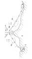
図1は本発明の1実施例としての航海計画支援システムを示すブロック図、図2(a),(b)は上記航海計画支援システムにおけるフローチャート、図3は上記航海計画支援システムによる航路選択の一例を示す平面図、図4は上記航海計画支援システムによる航路選択の他の例を示す平面図である。 FIG. 1 is a block diagram showing a navigation plan support system as one embodiment of the present invention, FIGS. 2 (a) and 2 (b) are flowcharts in the navigation plan support system, and FIG. 3 shows route selection by the navigation plan support system. FIG. 4 is a plan view showing another example of route selection by the navigation planning support system.
図3,4に示すように、A港からB港へ到る航路1を航行する可変ピッチプロペラを備えた電気推進船としての船舶2のための航海計画支援システムとして、図1に示す設備が船上および陸上に設けられている。
すなわち、船上設備3Aには、海象等計測装置4,危険海域情報・波浪推算データ受信装置5および同装置5から運航のための航路選択,航路上の通過点選択を行う航路選択装置5′が設けられるとともに、これらの装置4,5,5′から計測内容や受信内容を受け、波等による船舶の減速量等を求める応答データベース6を介して、通過予定時刻設定および船速舵角設定を行う運航計画演算装置7が設けられ、航路選択装置5′および運航計画演算装置7により設定される航路や通過点,通過予定時刻および船速,主機の負荷率,プロペラ翼角ならびに舵角は、表示部8に表示されるようになっている。As shown in FIGS. 3 and 4, the facility shown in FIG. 1 is used as a navigation plan support system for a
That is, the
そして、運航計画演算装置7から船速設定信号および舵角設定信号を受けることにより船速舵角制御装置9が作動して、図示しない主機関の制御およびプロペラ翼角の制御や操舵系における舵角制御が行われる。 Then, the ship speed steering angle control device 9 is activated by receiving the ship speed setting signal and the steering angle setting signal from the operation
また、船速舵角制御装置9からの信号を受けて次の通過点および通過予定時刻を予測するとともに、現在位置を確認し、これらの情報を陸上設備3Cの受信部10aへ発信する発信部10が設けられている。発信部10では上述のように受信した情報を運航管理装置10bへ伝達する。 In addition, it receives a signal from the ship speed rudder angle control device 9, predicts the next passing point and scheduled passing time, confirms the current position, and transmits the information to the receiving unit 10a of the land facility 3C. 10 is provided. The transmitting
さらに陸上設備3Bには、危険海域情報・波浪推算データ受信装置5へ情報およびデータを発信する危険海域情報・波浪推算データ発信装置5aが設けられるとともに、同装置5aへ情報およびデータを送るための波浪推算データ演算装置5bが設けられている。 Further, the
上述のように構成される航海計画支援システムでは、図2(a),(b)に示すフローチャートのごとく、「応答データベース」および「最適化」のための制御,演算等の作用が行われる。 In the navigation plan support system configured as described above, operations such as control and calculation for “response database” and “optimization” are performed as shown in the flowcharts of FIGS.
上述の航海計画支援システムを用いて、船舶2の運航が図3に示す航路1に沿って行われる場合、同航路1の選択は次のように行われる。
すなわち、座礁の危険海域12aおよび漁船の輻輳する漁場としての危険海域12bを回避できるように、同海域12a,12bの情報を図1の船上設備3における受信装置5が受けるのに伴い、航路選択装置5′における航路選択手段により航路1の選択が行われ、同航路1の表示が表示部8において行われる。When the
That is, as the
そして、航路1における多数の通過点1−1,1−2,・・・,1−10の選択も、航路選択装置5′における通過点選択手段により行われる。
さらに、運航計画演算装置7では、船舶2の現在の位置および時刻ならびにB港への到着予定時刻が入力されるのに伴い、応答データベース6からの海象等の情報に応じて、各通過点1−1,1−2,・・・,1−10における船舶2の通過予定時刻が、通過予定時刻設定手段により演算される。Then, selection of a large number of passing points 1-1, 1-2,..., 1-10 in the route 1 is also performed by passing point selection means in the
Further, in the operation
そして、上記各通過点を船舶2が実際に通過する時刻に応じて通過点間の船速や舵角の修正が行われる。
すなわち、B港への入港時刻が所要の予定時刻と一致するように、運航計画演算装置7における船速舵角設定手段および船速舵角制御装置9によって順次航海速度および舵角の設定が行われる。なお、図3において、符号Gは陸地を示し、Hは防波堤、Kは桟橋を示している。Then,the ship speed and the rudder anglebetween the passing points are corrected according to the time when the
That is, the navigation speed and the steering angle are sequentially set by the ship speed rudder angle setting means and the ship speed rudder angle control device 9 in the operation
図4に示す航路1の設定例では、漁場12cで漁船の操業が行われないとの情報に基づき、同漁場12cを通り抜けるように航路1の選択が行われた場合を示しているが、この例では海象情報に含まれる風Wの風向,風速および波Xの波高,波周期,波向、ならびに海・潮流Yの流向,流速の各データに応じ、船舶2の運航限界を考慮しながら船速舵角制御を行い、舵角制御には当て舵の量も自動的に配慮されるようになっている。 In the setting example of the route 1 shown in FIG. 4, the case where the route 1 is selected so as to pass through the
本発明の航海計画支援システムによれば、ロボットによる船舶の運航も可能であり、船長はロボットの行う操船を監視するだけでよいことになる。また、船橋等から見える船外の状況をビデオカメラで撮影して、その映像をレーダー情報等のデータと共に陸上の基地に絶えず送信することにより、船長と陸上基地との緊密な連絡と相まって、安全な航海を実現することが可能になる。 According to the navigation planning support system of the present invention, a ship can be operated by a robot, and the master only has to monitor the maneuvering performed by the robot. In addition, the situation outside the ship that can be seen from the bridge, etc. is shot with a video camera, and the video is constantly transmitted to the land base together with radar information, etc. Voyage can be realized.
1 航路
1−1,1−2,・・・,1−10 通過点
2 船舶
3A 船上設備
3B,3C 陸上設備
4 海象等計測装置
5 危険海域情報・波浪推算データ受信装置
5′ 航路選択装置
5a 危険海域情報・波浪推算データ発信装置
5b 波浪推算データ演算装置
6 応答データベース
7 運航計画演算装置
8 表示部
9 船速舵角制御装置
10 発信部
10a 受信部
10b 運航管理装置
12a 暗礁の危険海域
12b 漁場の危険海域
12c 漁場
G 陸地
H 防波堤
K 桟橋
W 風
X 波
Y 海・潮流DESCRIPTION OF SYMBOLS 1 Passage 1-1, 1-2, ..., 1-10
10 Transmitter
10a Receiver
10b Flight management device
12a Dangerous reef area
12b Dangerous waters of fishing grounds
12c Fishing ground G Land H Breakwater K Pier W Wind X Wave Y Sea / tide
Claims (2)
Translated fromJapanesePriority Applications (1)
| Application Number | Priority Date | Filing Date | Title |
|---|---|---|---|
| JP2003406477AJP3950975B2 (en) | 2003-12-04 | 2003-12-04 | Navigation planning support system |
Applications Claiming Priority (1)
| Application Number | Priority Date | Filing Date | Title |
|---|---|---|---|
| JP2003406477AJP3950975B2 (en) | 2003-12-04 | 2003-12-04 | Navigation planning support system |
Publications (2)
| Publication Number | Publication Date |
|---|---|
| JP2005162117A JP2005162117A (en) | 2005-06-23 |
| JP3950975B2true JP3950975B2 (en) | 2007-08-01 |
Family
ID=34728841
Family Applications (1)
| Application Number | Title | Priority Date | Filing Date |
|---|---|---|---|
| JP2003406477AExpired - LifetimeJP3950975B2 (en) | 2003-12-04 | 2003-12-04 | Navigation planning support system |
Country Status (1)
| Country | Link |
|---|---|
| JP (1) | JP3950975B2 (en) |
Cited By (1)
| Publication number | Priority date | Publication date | Assignee | Title |
|---|---|---|---|---|
| JP2008024187A (en)* | 2006-07-21 | 2008-02-07 | National Maritime Research Institute | Marine electric propulsion system |
Families Citing this family (13)
| Publication number | Priority date | Publication date | Assignee | Title |
|---|---|---|---|---|
| JP4756331B2 (en)* | 2005-08-10 | 2011-08-24 | 独立行政法人海上技術安全研究所 | Environmental load reduction type navigation plan providing system |
| JP2007245935A (en)* | 2006-03-16 | 2007-09-27 | Japan Agengy For Marine-Earth Science & Technology | Navigation planning support device |
| JP4970346B2 (en)* | 2008-05-28 | 2012-07-04 | 三井造船株式会社 | Ship operation support system and ship operation support method |
| JP2010121947A (en)* | 2008-11-17 | 2010-06-03 | Alpine Electronics Inc | Method and system for navigation for shipping |
| KR101222295B1 (en) | 2011-05-18 | 2013-01-15 | 제주대학교 산학협력단 | The Method and Apparatus for Preventing Deviation of Ship Seaway for Safety Navigation |
| JP6076611B2 (en)* | 2012-04-11 | 2017-02-08 | 古野電気株式会社 | Route planning apparatus and route plan verification method |
| EP2669630A1 (en)* | 2012-06-01 | 2013-12-04 | ABB Technology AG | Method and system for determination of a route for a ship |
| JP6121317B2 (en)* | 2013-12-25 | 2017-04-26 | 三菱重工業株式会社 | Ship speed control device, ship speed control system, ship speed control method, and ship speed control program |
| JP6038087B2 (en)* | 2014-09-22 | 2016-12-07 | 三菱重工業株式会社 | Ship operation plan optimization system and ship operation plan optimization method |
| KR101895129B1 (en)* | 2016-12-19 | 2018-10-04 | 한국해양과학기술원 | The sailing safety diagnosis system for stormy weather situation |
| CN115515851A (en)* | 2020-05-15 | 2022-12-23 | 国立研究开发法人海上·港湾·航空技术研究所 | Automatic guidance method of ship, automatic guidance program of ship, automatic guidance system of ship and ship |
| JP7712656B2 (en)* | 2021-05-17 | 2025-07-24 | 国立研究開発法人 海上・港湾・航空技術研究所 | Method for operating an autonomous ship, method for risk analysis, operation system, and risk analysis system |
| CN115496307B (en)* | 2022-11-21 | 2023-03-24 | 中国水产科学研究院南海水产研究所 | Fishery ship production method, system and medium based on Internet of things communication |
- 2003
- 2003-12-04JPJP2003406477Apatent/JP3950975B2/ennot_activeExpired - Lifetime
Cited By (1)
| Publication number | Priority date | Publication date | Assignee | Title |
|---|---|---|---|---|
| JP2008024187A (en)* | 2006-07-21 | 2008-02-07 | National Maritime Research Institute | Marine electric propulsion system |
Also Published As
| Publication number | Publication date |
|---|---|
| JP2005162117A (en) | 2005-06-23 |
Similar Documents
| Publication | Publication Date | Title |
|---|---|---|
| US20230192262A1 (en) | Automatic guiding method of vessel, automatic guiding program of vessel, automatic guiding system of vessel, and vessel | |
| JP3950975B2 (en) | Navigation planning support system | |
| CN111090278A (en) | Automatic navigation system based on ocean weather forecast | |
| US9927529B2 (en) | Programmable buoy system | |
| US9933536B2 (en) | Arctic seismic surveying operations | |
| JP6069273B2 (en) | Ship navigation promotion system and method in a specific water environment | |
| WO2020206380A1 (en) | Passage planning and navigation systems and methods | |
| JP2015037936A5 (en) | ||
| KR101719142B1 (en) | Ship navigation apparatus and method for providing route information for ship | |
| JP6251842B2 (en) | Ship operation support system and ship operation support method | |
| EP3696078B1 (en) | A method and system for piloting an unmanned surface vessel | |
| KR20170023737A (en) | Ship navigation apparatus and method for providing route information for ship | |
| US20190225307A1 (en) | Towboat and operations thereof | |
| CN112533823B (en) | Method for evaluating influence of shallow water | |
| WO2014145861A1 (en) | Arctic seismic surveying operations | |
| JP4853946B2 (en) | Ship operation support system for port entry | |
| Tannuri et al. | Application of a maneuvering simulation center and pilots expertise to the design of new ports and terminals and infrastructure optimization in Brazil | |
| Hooyer | Behavior and handling of ships | |
| Verwilligen et al. | Full-scale measurements of vertical motions on ultra large container vessels in Scheldt estuary | |
| KR20250012117A (en) | Shipbuilding system and shipbuilding method | |
| JP4572380B2 (en) | Sailing ship navigation planning support system | |
| US8543268B2 (en) | Cumulative lateral slide indication | |
| CN100504960C (en) | Method and simulation device for training ship pilots | |
| JP6621102B1 (en) | Ship position control system and ship equipped with the system | |
| RU2823051C1 (en) | Method of controlling coordinated group activity of automatic tugs |
Legal Events
| Date | Code | Title | Description |
|---|---|---|---|
| A977 | Report on retrieval | Free format text:JAPANESE INTERMEDIATE CODE: A971007 Effective date:20060515 | |
| A131 | Notification of reasons for refusal | Free format text:JAPANESE INTERMEDIATE CODE: A131 Effective date:20060524 | |
| A521 | Request for written amendment filed | Free format text:JAPANESE INTERMEDIATE CODE: A523 Effective date:20060721 | |
| TRDD | Decision of grant or rejection written | ||
| A01 | Written decision to grant a patent or to grant a registration (utility model) | Free format text:JAPANESE INTERMEDIATE CODE: A01 Effective date:20070322 | |
| R150 | Certificate of patent or registration of utility model | Ref document number:3950975 Country of ref document:JP Free format text:JAPANESE INTERMEDIATE CODE: R150 Free format text:JAPANESE INTERMEDIATE CODE: R150 | |
| S533 | Written request for registration of change of name | Free format text:JAPANESE INTERMEDIATE CODE: R313533 | |
| R350 | Written notification of registration of transfer | Free format text:JAPANESE INTERMEDIATE CODE: R350 | |
| S533 | Written request for registration of change of name | Free format text:JAPANESE INTERMEDIATE CODE: R313533 | |
| R350 | Written notification of registration of transfer | Free format text:JAPANESE INTERMEDIATE CODE: R350 | |
| EXPY | Cancellation because of completion of term |