JP3950302B2 - Pumping liquid cooler using phase change coolant - Google Patents
Pumping liquid cooler using phase change coolantDownload PDFInfo
- Publication number
- JP3950302B2 JP3950302B2JP2001104315AJP2001104315AJP3950302B2JP 3950302 B2JP3950302 B2JP 3950302B2JP 2001104315 AJP2001104315 AJP 2001104315AJP 2001104315 AJP2001104315 AJP 2001104315AJP 3950302 B2JP3950302 B2JP 3950302B2
- Authority
- JP
- Japan
- Prior art keywords
- liquid
- coolant
- air
- pump
- heat
- Prior art date
- Legal status (The legal status is an assumption and is not a legal conclusion. Google has not performed a legal analysis and makes no representation as to the accuracy of the status listed.)
- Expired - Fee Related
Links
- 239000007788liquidSubstances0.000titleclaimsdescription87
- 239000002826coolantSubstances0.000titleclaimsdescription60
- 238000005086pumpingMethods0.000titledescription4
- 238000001816coolingMethods0.000claimsdescription32
- 238000000034methodMethods0.000claimsdescription12
- 239000012080ambient airSubstances0.000claimsdescription6
- 238000001704evaporationMethods0.000claimsdescription5
- 230000005611electricityEffects0.000claims1
- 239000012530fluidSubstances0.000description18
- 239000012071phaseSubstances0.000description10
- 239000003570airSubstances0.000description9
- 238000009833condensationMethods0.000description7
- 230000005494condensationEffects0.000description7
- 230000006835compressionEffects0.000description5
- 238000007906compressionMethods0.000description5
- 230000005484gravityEffects0.000description5
- XLYOFNOQVPJJNP-UHFFFAOYSA-NwaterSubstancesOXLYOFNOQVPJJNP-UHFFFAOYSA-N0.000description4
- 239000007791liquid phaseSubstances0.000description3
- 230000008020evaporationEffects0.000description2
- 238000010438heat treatmentMethods0.000description2
- 239000002184metalSubstances0.000description2
- 239000000203mixtureSubstances0.000description2
- 230000007797corrosionEffects0.000description1
- 238000005260corrosionMethods0.000description1
- 238000010586diagramMethods0.000description1
- 238000007865dilutingMethods0.000description1
- 238000001035dryingMethods0.000description1
- 230000000694effectsEffects0.000description1
- 239000000314lubricantSubstances0.000description1
- 238000004377microelectronicMethods0.000description1
- 238000005057refrigerationMethods0.000description1
- 238000007789sealingMethods0.000description1
- 239000004065semiconductorSubstances0.000description1
- 239000012808vapor phaseSubstances0.000description1
Images

Classifications
- H—ELECTRICITY
- H01—ELECTRIC ELEMENTS
- H01L—SEMICONDUCTOR DEVICES NOT COVERED BY CLASS H10
- H01L23/00—Details of semiconductor or other solid state devices
- H01L23/34—Arrangements for cooling, heating, ventilating or temperature compensation ; Temperature sensing arrangements
- H01L23/42—Fillings or auxiliary members in containers or encapsulations selected or arranged to facilitate heating or cooling
- H01L23/427—Cooling by change of state, e.g. use of heat pipes
- F—MECHANICAL ENGINEERING; LIGHTING; HEATING; WEAPONS; BLASTING
- F25—REFRIGERATION OR COOLING; COMBINED HEATING AND REFRIGERATION SYSTEMS; HEAT PUMP SYSTEMS; MANUFACTURE OR STORAGE OF ICE; LIQUEFACTION SOLIDIFICATION OF GASES
- F25B—REFRIGERATION MACHINES, PLANTS OR SYSTEMS; COMBINED HEATING AND REFRIGERATION SYSTEMS; HEAT PUMP SYSTEMS
- F25B23/00—Machines, plants or systems, with a single mode of operation not covered by groups F25B1/00 - F25B21/00, e.g. using selective radiation effect
- F25B23/006—Machines, plants or systems, with a single mode of operation not covered by groups F25B1/00 - F25B21/00, e.g. using selective radiation effect boiling cooling systems
- F—MECHANICAL ENGINEERING; LIGHTING; HEATING; WEAPONS; BLASTING
- F28—HEAT EXCHANGE IN GENERAL
- F28D—HEAT-EXCHANGE APPARATUS, NOT PROVIDED FOR IN ANOTHER SUBCLASS, IN WHICH THE HEAT-EXCHANGE MEDIA DO NOT COME INTO DIRECT CONTACT
- F28D15/00—Heat-exchange apparatus with the intermediate heat-transfer medium in closed tubes passing into or through the conduit walls ; Heat-exchange apparatus employing intermediate heat-transfer medium or bodies
- F28D15/02—Heat-exchange apparatus with the intermediate heat-transfer medium in closed tubes passing into or through the conduit walls ; Heat-exchange apparatus employing intermediate heat-transfer medium or bodies in which the medium condenses and evaporates, e.g. heat pipes
- F28D15/0266—Heat-exchange apparatus with the intermediate heat-transfer medium in closed tubes passing into or through the conduit walls ; Heat-exchange apparatus employing intermediate heat-transfer medium or bodies in which the medium condenses and evaporates, e.g. heat pipes with separate evaporating and condensing chambers connected by at least one conduit; Loop-type heat pipes; with multiple or common evaporating or condensing chambers
- H—ELECTRICITY
- H01—ELECTRIC ELEMENTS
- H01L—SEMICONDUCTOR DEVICES NOT COVERED BY CLASS H10
- H01L23/00—Details of semiconductor or other solid state devices
- H01L23/34—Arrangements for cooling, heating, ventilating or temperature compensation ; Temperature sensing arrangements
- H01L23/46—Arrangements for cooling, heating, ventilating or temperature compensation ; Temperature sensing arrangements involving the transfer of heat by flowing fluids
- H01L23/473—Arrangements for cooling, heating, ventilating or temperature compensation ; Temperature sensing arrangements involving the transfer of heat by flowing fluids by flowing liquids
- H—ELECTRICITY
- H01—ELECTRIC ELEMENTS
- H01L—SEMICONDUCTOR DEVICES NOT COVERED BY CLASS H10
- H01L2924/00—Indexing scheme for arrangements or methods for connecting or disconnecting semiconductor or solid-state bodies as covered by H01L24/00
- H01L2924/0001—Technical content checked by a classifier
- H01L2924/0002—Not covered by any one of groups H01L24/00, H01L24/00 and H01L2224/00
Landscapes
- Engineering & Computer Science (AREA)
- Physics & Mathematics (AREA)
- Power Engineering (AREA)
- General Physics & Mathematics (AREA)
- Computer Hardware Design (AREA)
- Microelectronics & Electronic Packaging (AREA)
- Condensed Matter Physics & Semiconductors (AREA)
- Thermal Sciences (AREA)
- Mechanical Engineering (AREA)
- General Engineering & Computer Science (AREA)
- Life Sciences & Earth Sciences (AREA)
- Sustainable Development (AREA)
- Cooling Or The Like Of Electrical Apparatus (AREA)
- Cooling Or The Like Of Semiconductors Or Solid State Devices (AREA)
Description
Translated fromJapanese【0001】
【発明の属する技術分野】
本発明は、電気要素および電子要素の冷却に関し、さらに詳しく言えば、冷却剤を冷却されるべき電気要素または電子要素と熱接触状態で多数の冷板/蒸発器へ循環させる液体冷却剤ポンプに関するものである。
【0002】
本願は、2000年4月4日に出願された予備出願第60/194,381号にもとづく正規の出願である。
【0003】
【従来の技術】
電気要素および電子要素(例えば、マイクロプロセッサ、IGBT、出力半導体等)は、冷却されるべき表面に直接に取り付けられた伸展表面をもつ空冷ヒートシンクによって最もしばしば冷却される。ファンまたはブロワは、ヒートシンク・フィンを横切って空気を移動させ、それらの要素によって発生された熱を取り除いている。増大する電力密度、要素の小型化、包装の収縮のために、ヒートシンクおよび強制空気流によっては電気要素および電子要素を十分に冷却することは、ときには困難になる。これが起きると、その他の方法が要素から熱を除去するように採用されなければならない。
【0004】
直接空冷が可能でない場合、要素から熱を除去する一方法は、冷板へ汲み出される単相流体を使用する。冷板は、平らな金属板に取り付けられた蛇行管を有する。冷却されるべき要素平板に熱的に取り付けられ、また、蛇行管を流れる汲出し単相流体が要素によって発生された熱を除去する。
【0005】
多くの形式の冷板設計がある。そのうちのいくつかは、流体を運ぶ管に代えて機械加工溝を取り入れている。しかし、すべての冷板設計は、熱を除去すべき流体の感知可能加熱を用いることによって同様に動作する。加熱流体は、周囲の空気がポンプまで戻り、再びサイクルを開始する前に、周囲の空気が流体を冷却する場合には、遠隔に配置された空冷コイルまで流れる。電気要素および電子要素から熱を除去するように流体の感知可能加熱を用いるこの方法は、単相流動流の熱容量によって制限される。より多くの熱を除去する所定の流体については、その温度が増加しなければならないか、あるいはより多くの流体が汲み出されなければならない。これは、高出力超小型電子技術装置を冷却するように高温および/または大流量を発生する。高温は電気装置または電子素子を破損し、一方、大流量は大型モータを備えたポンプを必要とする。大型モータは、渦流電力を消費し、冷却装置の適用を制限する。大流量は、高流体速度による冷板内の金属の腐食を発生することもある。
【0006】
空冷が実施できない場合に要素から熱を除去する別の方法は、熱がより容易に放散される箇所まで熱源から熱を伝達するヒートパイプを使用する。ヒートパイプは、ある箇所から別の箇所へ熱を移動させるように凝縮可能流体を使用する密封装置である。流体搬送は、芯構造を用いる液体の毛細管汲出しによって達成される。ヒートパイプの一端(蒸発器)は熱が要素に発生される箇所に配置され、また、ヒートパイプの他端(凝縮器)は熱が放散される箇所に配置される。凝縮器端は、熱を周囲の空気へ取り去ることを助けるようにフィンのような伸展表面にしばしば接触する。熱を除去するこの方法は、流体を蒸発器へ搬送する芯構造の能力によって制限される。高温流動においては、芯構造が十分な流体を蒸発器へ搬送できない場合には、「完全乾燥(dry out)」として知られる状態が起こり、装置の温度が増加し、装置に損害を多分与える。ヒートパイプは、重力に関して向きに敏感でもある。すなわち、上向きに設けられた蒸発器は、流体搬送が芯構造の毛細管作用に加えて重力によって補助される場合に、下向きに設けられた蒸発器よりも熱を除去する能力が小さい。最後に、ヒートパイプは、毛細管汲出し制限のために遠隔放散器まで長距離にわたって熱を搬送できない。
【0007】
直接空冷が実用的ではない場合に採られるさらに別の方法は、周知の蒸気圧縮冷却サイクルを使用する。この場合、冷板はサイクルの蒸発器となる。コンプレッサが蒸気の温度および圧力を上昇し、空冷凝縮器が蒸気を液体状態に凝縮し、かつ、さらに蒸発および冷却のために冷板へ戻されるように用いられるようなレベルに蒸発器を維持する。この方法は、高等温熱伝達率および熱を相当な距離動かす能力の利点を有する。しかし、この方法は、電気要素および電子要素を冷却するさいにその実際的用途を制限するいくつかの主要な欠点を受ける。第一に、コンプレッサの電力消費がある。高熱付加用途においては、コンプレッサによって要求される電力は重要になり、用途のために入手できる電力を超える。別の問題は、周囲温度以下の蒸発器(冷板)の作動に関することである。この場合、適正に絶縁された表面は、周囲温度の露点以下になることがあり、水の凝縮を生じ、短絡および人間へ危険を及ぼす機械をつくる。蒸気圧縮冷却サイクルは、潤滑油を希釈することによってコンプレッサに物理的損害を与えかつその寿命を縮めるコンプレッサへのいかなる液体冷却剤をも戻さないように設計されている。電気要素および電子要素を冷却するさいに、熱負荷は高度に変化し、非蒸発冷却剤を冷板から出し、コンプレッサに入れる。これは、コンプレッサに損害を与え、その寿命を縮める。これは、要素にとって蒸気圧縮冷却の別の欠点でもある。
【0008】
空冷が実施できないとき、要素から熱を除去する改良された方法についての連続した要求があることがわかる。
【0009】
【発明が解決しようとする課題】
したがって、本発明の目的は、電気要素および電子要素に冷却を与えることにある。本発明の別の目的は、非常に低い渦流電力消費および要素表面から離れた非常に高い熱伝達率で要素に冷却を与えることにある。本発明のさらに別の目的は、要素から周囲ヒートシンクへ熱を移動するのに要する温度低下を減じることにある。
【0010】
【課題を解決するための手段】
上記の要求は、本発明の汲出し液体冷却装置によって満たされる。その装置においては、非常に低い実用電力消費および要素表面からの非常に高い熱伝達率で電気要素および電子要素に冷却が与えられる。本発明は、熱を要素から周囲ヒートシンクまで移動させるように要求された温度低下を減じる。
【0011】
本発明の一観点によれば、液体冷却剤ポンプが冷却剤を冷却されるべき電気要素または電子要素と熱接触する冷板/蒸発器へ循環させる。液体冷却剤は、要素によって発生された熱によって部分的にまたは完全に蒸発される。蒸気は慣用の凝縮器によって凝縮され、また、任意の非蒸発液体と共に凝縮された液体がポンプに戻される。本発明の装置は、蒸発および凝縮においてほぼ等温に動作する。
【0012】
【発明の実施の形態】
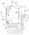
図1において、作業流体として冷却剤を循環する冷却装置10が示されている。冷却剤は、R−134aのような任意の蒸発可能冷却剤でもよい。冷却サイクルは、密封液体ポンプとして知られている液体ポンプ12において開始する。ポンプ12は、液相冷却剤を液体マニフォルド14へ汲み出す。そこで、冷却剤は複数の支流またはライン16へ分配される。多くの支流(ライン)が取り付けられている場合を示すために、追加の液体マニフォルド14a、14b、14nが示される。支流の実際の数は装置によって冷却されるべき要素の数によって決まる。マニフォルド14から、各支流またはライン16が液体冷却剤を冷板18に送給する。
【0013】
図2に示すように、各冷板18は冷却されるべき電気要素または電子要素20と熱接触して、液体冷却剤を装置圧力で蒸発させる。液体冷却剤が皆無、いくらか、またはすべてが、いかに多くの熱を要素20によって発生しつつあるかにもとづいて、冷板18において蒸発することもある。最も多くの場合には、いくらかの冷却剤が蒸発され、また、液体および蒸気冷却剤の二相混合体が矢印22で示すように、各冷板18に残る。
【0014】
本発明の好適実施例においては、この点において装置の運転のさいに、図1に示すように、各冷板18が二相冷却剤の混合体を蒸気/液体分離器24へ放出する。最も多くの用途については、蒸気/液体分離器24は、軽い蒸気が管の頂部へ上昇する間に、重い冷却剤が重力によって管の底部へ降下させるのに十分な直径の垂直管である。このようにして、いかなる非蒸発冷却剤も蒸気から分離され、各相が装置内で別個に処理される。
【0015】
蒸気/液体分離器24は、凝縮コイル30およびファン32からなる凝縮器28に繋がる蒸気ライン26に取り付けられる。追加の蒸気/液体分離器24a、24b、24nは、装置の冷却容量が増加されるように、蒸気マニフォルドの使用をかいして接続される。蒸気ライン26に取り付けられた凝縮器コイル30は、液相へ戻る蒸気相を凝縮し、そして電子要素20によって発生された熱を除去する。空冷凝縮器、水もしくは液体冷却凝縮器または蒸発凝縮器のような熱拒絶の任意の適切な形体は、本発明の範囲から逸脱せずに用いられることは当該技術において起こりうるが、ファン32を用いる周囲空冷凝縮器28が図1に示されている。
【0016】
凝縮器28は、周囲空気の温度よりもいくぶん高い温度に対応する圧力で動作する。このようにして、装置温度が周囲露点温度以下にならないので、凝縮が発生することは不可能である。凝縮動作点が、熱を凝縮器から除去するように到来冷却剤温度およびその能力によって全体の装置の圧力を設定し、凝縮温度および圧力を固定する。また、蒸発された冷却剤が液相に凝縮されつつあるので、凝縮器28は、蒸気を冷板―蒸発器18から凝縮器28まで移動させるいかなるコンプレッサの必要もなしに、蒸気/液体分離器24から凝縮器28へ蒸発された冷却剤の流れをつくる。液体冷却剤は矢印34で示すように凝縮器28を出て、重力によって液体受容器36まで動き、そこである量の液体凝縮を保持する。
【0017】
本発明の一実施例においては、蒸気/液体分離器24からの第2選択液体戻りライン38が液体受容器36に接続される。代案として、すべての液体はライン26をかいしてポンプ12へ戻され、蒸気を液体に戻すように凝縮器28を通過する。液体戻しライン38の追加によって、液体冷却剤の2つの源がある。液体冷却剤の一方の源は、凝縮器からのものであり、他方の源は分離器からのものである。ライン26もしくはライン38またはその両者が、分離器24から液体受容器36までいかなる非蒸発液体冷却剤をも運ぶように使用されうる。そこでは、非蒸発液体冷却剤が再びサイクル内で使用される。したがって、液体受容器は凝縮器からまたは分離器から液体を受ける。液体受容器36に保持されたある量の液体冷却剤は、ポンプ12の入口の上に液頭(圧)を与えるので、ポンプは信頼性をもって運転する。液体受容器36は、液溜を貯蔵冷却剤に与えることによって装置10内の液体冷却剤量の変化をも取り扱う。液溜の出口は、液体冷却剤ポンプ12の入口に接続される。ポンプ12において、冷却剤の圧力は装置内の摩擦損失に打ち克つのに十分に上昇され、そして、冷却サイクルが再度開始する。ポンプ12は、その圧力上昇が設計流量において装置内の摩擦損失に等しいかまたは超えるように、選定される。
【0018】
【発明の効果】
本発明は液体冷却剤の感知できる熱容量よりもむしろ熱を除去するように相変化を使用するので、汲出し液体単相装置とは相違して、本発明は等温で動作する。これは、単相液体装置よりも蒸発器において低い温度でかつ低温要素について許す。低い液体流量が、熱を除去するように作業流体の蒸発器をかいして達成され、流体速度を低く、ポンプ電力を除去される熱に対して非常に低く維持する。渦流電力が汲出し液体単相装置および蒸気圧縮冷却剤装置に対して低減される。
【0019】
ヒートパイプ装置による利点は、液体流量がヒートパイプにおけるように毛細管作用に依存しないので、本発明の装置10によって得られ、液体ポンプの流量を設定することによって独立して設定されうる。したがって、完全乾燥が回避される。本発明の冷板/蒸発器装置は、重力に関する向きに敏感ではない。ヒートパイプ装置とは相違して、本発明の蒸発器18の熱容量は特定の向きにおいては減少しない。
【0020】
ヒートパイプおよび蒸気圧縮系装置に優る本発明の別の利点は、大きな距離にわたって蒸発器および凝縮器を分離する能力である。これは、装置の小型化および設計構造により多くの融通性を許す。本発明によれば、液体および蒸気が独立して搬送され、液体および蒸気ラインのサイズの最少化を許す。本発明は、冷却されるべき要素20の熱負荷の変動を容易に取り扱う。いかなる非蒸発液体冷却剤もポンプに戻されないので、変動負荷における多冷板はコンプレッサを故障させずに容易に達成される。本発明は周囲露点温度以下の温度では装置10内の任意の点で動作しないので、水蒸気凝縮および水の生成の可能性がない。
【図面の簡単な説明】
【図1】本発明にもとづく汲出し液体冷却装置を示す概略構成線図である。
【図2】冷却されるべき要素にそれぞれ熱接触した状態にある複数の冷板蒸発器装置の斜視図である。
【符号の説明】
10:冷却装置、12:液体ポンプ、14:液体マニフォルド、16:支流(ライン)、18:冷板、20:要素、24蒸気/液体分離器:、26:蒸気ライン、28:凝縮器、30:凝縮器コイル、32:ファン、36:液体受容器、38:液体戻りライン。[0001]
BACKGROUND OF THE INVENTION
The present invention relates to cooling of electrical and electronic elements, and more particularly to a liquid coolant pump that circulates coolant to a number of cold plates / evaporators in thermal contact with the electrical or electronic element to be cooled. Is.
[0002]
This application is a regular application based on preliminary application No. 60 / 194,381 filed on Apr. 4, 2000.
[0003]
[Prior art]
Electrical and electronic elements (e.g., microprocessors, IGBTs, output semiconductors, etc.) are most often cooled by air-cooled heat sinks with stretched surfaces attached directly to the surface to be cooled. A fan or blower moves air across the heat sink fins to remove the heat generated by those elements. Due to increasing power density, element miniaturization, and package shrinkage, it is sometimes difficult to sufficiently cool electrical and electronic elements with heat sinks and forced air flow. When this happens, other methods must be employed to remove heat from the element.
[0004]
If direct air cooling is not possible, one method of removing heat from the element uses a single phase fluid that is pumped to a cold plate. The cold plate has a serpentine tube attached to a flat metal plate. A pumped single phase fluid that is thermally attached to the element plate to be cooled and flows through the serpentine tube removes the heat generated by the element.
[0005]
There are many forms of cold plate design. Some of them incorporate machined grooves instead of fluid carrying tubes. However, all cold plate designs operate similarly by using sensitive heating of the fluid from which heat is to be removed. The heated fluid flows to a remotely located air cooling coil if the ambient air cools the fluid before the ambient air returns to the pump and begins the cycle again. This method of using sensitive heating of the fluid to remove heat from the electrical and electronic elements is limited by the heat capacity of the single phase flow stream. For a given fluid that removes more heat, its temperature must increase or more fluid must be pumped. This generates high temperatures and / or high flow rates to cool the high power microelectronic devices. High temperatures damage electrical devices or electronic elements, while large flow rates require a pump with a large motor. Large motors consume eddy currents and limit the application of cooling devices. High flow rates can cause corrosion of the metal in the cold plate due to high fluid velocities.
[0006]
Another method of removing heat from the element when air cooling cannot be performed uses a heat pipe that transfers heat from the heat source to where it is more easily dissipated. A heat pipe is a sealing device that uses a condensable fluid to transfer heat from one location to another. Fluid delivery is achieved by liquid capillary pumping using a core structure. One end (evaporator) of the heat pipe is arranged at a place where heat is generated in the element, and the other end (condenser) of the heat pipe is arranged at a place where heat is dissipated. The condenser end often contacts an extension surface such as a fin to help remove heat to the surrounding air. This method of removing heat is limited by the ability of the core structure to carry fluid to the evaporator. In hot flow, if the core structure fails to carry enough fluid to the evaporator, a condition known as “dry out” occurs, increasing the temperature of the device and possibly damaging the device. Heat pipes are also sensitive to gravity. That is, the evaporator provided upwards has a smaller ability to remove heat than the evaporator provided downwards when fluid transport is assisted by gravity in addition to the capillary action of the core structure. Finally, heat pipes cannot carry heat over long distances to remote dissipators due to capillary pumping limitations.
[0007]
Yet another method taken when direct air cooling is not practical uses the well-known vapor compression cooling cycle. In this case, the cold plate becomes a cycle evaporator. The compressor raises the temperature and pressure of the vapor, and the air-cooled condenser condenses the vapor to a liquid state and maintains the evaporator at a level that can be used to return to the cold plate for further evaporation and cooling. . This method has the advantage of a high isothermal heat transfer coefficient and the ability to move heat a considerable distance. However, this method suffers from several major drawbacks that limit its practical application when cooling electrical and electronic elements. First, there is power consumption of the compressor. In high heat application, the power required by the compressor becomes important and exceeds the power available for the application. Another problem relates to the operation of evaporators (cold plates) below ambient temperature. In this case, a properly insulated surface can be below the dew point of ambient temperature, causing water condensation, creating a short circuit and a machine that poses a danger to humans. The vapor compression refrigeration cycle is designed not to return any liquid coolant to the compressor that causes physical damage to the compressor and diminishes its life by diluting the lubricant. In cooling the electrical and electronic elements, the heat load changes to a high degree and the non-evaporating coolant is removed from the cold plate and placed in the compressor. This damages the compressor and shortens its life. This is another disadvantage of vapor compression cooling for the element.
[0008]
When air cooling cannot be performed, it can be seen that there is a continuing need for improved methods of removing heat from the element.
[0009]
[Problems to be solved by the invention]
Accordingly, an object of the present invention is to provide cooling to electrical and electronic elements. Another object of the present invention is to provide element cooling with very low eddy power consumption and very high heat transfer rates away from the element surface. Yet another object of the present invention is to reduce the temperature drop required to transfer heat from the element to the ambient heat sink.
[0010]
[Means for Solving the Problems]
The above requirements are met by the pumped liquid cooling device of the present invention. In that device, cooling is provided to electrical and electronic elements with very low utility power consumption and very high heat transfer rate from the element surface. The present invention reduces the temperature drop required to transfer heat from the element to the ambient heat sink.
[0011]
According to one aspect of the invention, a liquid coolant pump circulates coolant to a cold plate / evaporator that is in thermal contact with the electrical or electronic element to be cooled. The liquid coolant is partially or completely evaporated by the heat generated by the element. The vapor is condensed by a conventional condenser and the liquid condensed with any non-evaporated liquid is returned to the pump. The apparatus of the present invention operates approximately isothermally during evaporation and condensation.
[0012]
DETAILED DESCRIPTION OF THE INVENTION
FIG. 1 shows a cooling device 10 that circulates a coolant as a working fluid. The coolant may be any evaporable coolant such as R-134a. The cooling cycle begins at a
[0013]
As shown in FIG. 2, each
[0014]
In the preferred embodiment of the present invention, during operation of the apparatus at this point, each
[0015]
The vapor / liquid separator 24 is attached to a vapor line 26 that leads to a condenser 28 consisting of a condensing
[0016]
The condenser 28 operates at a pressure corresponding to a temperature somewhat higher than the temperature of the ambient air. In this way, condensation cannot occur because the device temperature does not fall below the ambient dew point temperature. The condensation operating point sets the overall equipment pressure by the incoming coolant temperature and its ability to remove heat from the condenser and fixes the condensation temperature and pressure. Also, as the evaporated coolant is being condensed to the liquid phase, the condenser 28 is a vapor / liquid separator without the need for any compressor to move the vapor from the cold plate-
[0017]
In one embodiment of the present invention, a second selected
[0018]
【The invention's effect】
Unlike the pumped liquid single phase device, the present invention operates isothermally because the present invention uses phase change to remove heat rather than the sensible heat capacity of the liquid coolant. This allows for lower temperature and lower temperature elements in the evaporator than single phase liquid devices. A low liquid flow rate is achieved through the working fluid evaporator to remove heat, keeping the fluid velocity low and pump power very low with respect to the heat being removed. Eddy current power is reduced for the pumped liquid single phase device and the vapor compression coolant device.
[0019]
The advantages of the heat pipe device are obtained by the device 10 of the present invention since the liquid flow rate does not depend on capillary action as in a heat pipe and can be set independently by setting the flow rate of the liquid pump. Thus, complete drying is avoided. The cold plate / evaporator apparatus of the present invention is not sensitive to orientation with respect to gravity. Unlike heat pipe devices, the heat capacity of the
[0020]
Another advantage of the present invention over heat pipe and vapor compression system devices is the ability to separate the evaporator and condenser over large distances. This allows more flexibility in the miniaturization of the device and the design structure. In accordance with the present invention, liquid and vapor are carried independently, allowing the liquid and vapor line size to be minimized. The present invention easily handles variations in the thermal load of the
[Brief description of the drawings]
FIG. 1 is a schematic configuration diagram showing a pumping liquid cooling device according to the present invention.
FIG. 2 is a perspective view of a plurality of cold plate evaporator devices in thermal contact with each element to be cooled.
[Explanation of symbols]
10: cooling device, 12: liquid pump, 14: liquid manifold, 16: tributary (line), 18: cold plate, 20: element, 24 vapor / liquid separator :, 26: vapor line, 28: condenser, 30 : Condenser coil, 32: Fan, 36: Liquid receiver, 38: Liquid return line.
Claims (7)
Translated fromJapanese前記少なくとも1つの要素(20)に熱接触する少なくとも1つの冷板蒸発器装置(18)と、
液体冷却剤ポンプ(12)と、
該ポンプによって前記少なくとも1つの冷板蒸発器装置(18)へ循環される蒸発可能冷却剤であって、それにより、その蒸発可能冷却剤の少なくとも一部が前記少なくとも1つの要素(20)によって発生された熱によって蒸発されて蒸気を発生する、蒸発可能冷却剤と、
前記蒸気を凝縮して凝縮液体を発生する空冷凝縮器(28)と、
前記蒸発可能冷却剤を受けいれるための液体受容器(36)と、
前記冷却剤を前記ポンプへ戻すための、非蒸発液体冷却剤戻りライン(38)及び前記空冷凝縮器からの液体戻りライン(26)とを備えている、改良冷却装置であって、
前記改良冷却装置が、周囲空気の露点温度よりも高い前記改良冷却装置の温度に対応する前記冷却剤の圧力で作動するように、前記空冷凝縮器(28)を制御することができることを特徴とする、改良冷却装置。At least one element (20) required to generate heat and be cooled;
At least one cold plate evaporator device (18) in thermal contact with the at least one element (20);
A liquid coolant pump (12);
Evaporable coolant circulated by the pump to the at least one cold plate evaporator device (18), whereby at least a portion of the evaporable coolant is generated by the at least one element (20) An evaporable coolant that is evaporated by the generated heat to generate steam;
Anair-cooled condenser (28) for condensing the vapor to generate a condensed liquid;
A liquid receptacle (36) for receiving the evaporable coolant;
An improved cooling devicecomprising a non-evaporated liquid coolant return line (38) and a liquid return line (26) from theair-cooled condenser for returning the coolant to the pump,
Theair-cooled condenser (28) can be controlled so that the improved cooling device operates at a pressure of the coolant corresponding to a temperature of the improved cooling device that is higher than a dew point temperature ofambient air. An improved cooling system.
少なくとも1つの冷板蒸発器装置を1またはそれを超える電気要素または電子要素(20)に熱接触状態に配置することと、
液体冷却剤ポンプ(12)を設けることと、
冷却剤を設けることと、
液体の前記冷却剤を受けいれるための液体受容器(36)を設けることと、
前記液体冷却剤を前記液体冷却剤ポンプ(12)へ戻すことと、
前記液体冷却剤ポンプ(12)を用いて、前記少なくとも1つの冷板蒸発器装置(18)に前記冷却剤を循環させ、それによって、前記冷却剤の少なくとも一部が前記1またはそれを超える電気要素または電子要素(20)によって発生された熱によって蒸発されて、蒸気を発生することと、
空冷凝縮器(28)を用いて、前記蒸気を凝縮して、凝縮された液体を発生することと、
非蒸発液体戻りライン(38)を設けることと、
前記空冷凝縮器からの液体戻りライン(26)を設けることとを備え、
前記蒸気を凝縮する工程は、周囲空気の露点温度よりも高い前記改良冷却装置の温度に対応する前記冷却剤の圧力で作動する前記空冷凝縮器(28)によって、おこなわれることを特徴とする、冷却方法。A method of cooling one or more electrical or electronic elements (20) that generate heat and need to be cooled, comprising:
Placing at least one cold plate evaporator device in thermal contact with one or more electrical or electronic elements (20);
Providing a liquid coolant pump (12);
Providing a coolant,
Providing a liquid receptacle (36) for receiving said coolant of liquid;
Returning the liquid coolant to the liquid coolant pump (12);
The liquid coolant pump (12) is used to circulate the coolant through the at least one cold plate evaporator device (18) so that at least a portion of the coolant is in the one or more electricity. Evaporating by heat generated by the element or electronic element (20) to generate steam;
Using an air-cooled condenser (28) to condense the vapor to produce a condensed liquid;
Providing a non-evaporated liquid return line (38);
Providing a liquid return line (26) from theair-cooled condenser ,
The step of condensing the steam is performed by theair-cooled condenser (28) operating at the pressure of the coolant corresponding to the temperature of the improved cooling device higher than the dew point temperature ofambient air , Cooling method.
Applications Claiming Priority (4)
| Application Number | Priority Date | Filing Date | Title |
|---|---|---|---|
| US19438100P | 2000-04-04 | 2000-04-04 | |
| US60/194381 | 2001-03-28 | ||
| US09/819,591US6519955B2 (en) | 2000-04-04 | 2001-03-28 | Pumped liquid cooling system using a phase change refrigerant |
| US09/819591 | 2001-03-28 |
Publications (2)
| Publication Number | Publication Date |
|---|---|
| JP2001349651A JP2001349651A (en) | 2001-12-21 |
| JP3950302B2true JP3950302B2 (en) | 2007-08-01 |
Family
ID=22717379
Family Applications (1)
| Application Number | Title | Priority Date | Filing Date |
|---|---|---|---|
| JP2001104315AExpired - Fee RelatedJP3950302B2 (en) | 2000-04-04 | 2001-04-03 | Pumping liquid cooler using phase change coolant |
Country Status (5)
| Country | Link |
|---|---|
| US (2) | US6519955B2 (en) |
| EP (1) | EP1143778B1 (en) |
| JP (1) | JP3950302B2 (en) |
| CA (1) | CA2342570C (en) |
| DE (1) | DE60125085T2 (en) |
Families Citing this family (145)
| Publication number | Priority date | Publication date | Assignee | Title |
|---|---|---|---|---|
| US7630198B2 (en)* | 2006-03-08 | 2009-12-08 | Cray Inc. | Multi-stage air movers for cooling computer systems and for other uses |
| WO2001072099A2 (en)* | 2000-03-21 | 2001-09-27 | Liebert Corporation | Method and apparatus for cooling electronic enclosures |
| US6467295B2 (en)* | 2000-12-01 | 2002-10-22 | Lg Electronics Inc. | Refrigerated cooling apparatus for semiconductor device |
| JP3658317B2 (en)* | 2000-12-19 | 2005-06-08 | 株式会社日立製作所 | COOLING METHOD, COOLING SYSTEM, AND INFORMATION PROCESSING DEVICE |
| US6668570B2 (en)* | 2001-05-31 | 2003-12-30 | Kryotech, Inc. | Apparatus and method for controlling the temperature of an electronic device under test |
| US6942018B2 (en)* | 2001-09-28 | 2005-09-13 | The Board Of Trustees Of The Leland Stanford Junior University | Electroosmotic microchannel cooling system |
| DE10210480B4 (en)* | 2002-03-11 | 2005-07-21 | Rittal Gmbh & Co. Kg | cooling arrangement |
| JP2003318341A (en)* | 2002-04-25 | 2003-11-07 | Matsushita Electric Ind Co Ltd | Cooling device for semiconductor device |
| US6937471B1 (en) | 2002-07-11 | 2005-08-30 | Raytheon Company | Method and apparatus for removing heat from a circuit |
| US7000691B1 (en) | 2002-07-11 | 2006-02-21 | Raytheon Company | Method and apparatus for cooling with coolant at a subambient pressure |
| US7401472B2 (en)* | 2003-01-17 | 2008-07-22 | Tecumseh Products Company | Modular heating or cooling system |
| US7806166B1 (en) | 2003-02-18 | 2010-10-05 | Parker-Hannifin Corporation | Insulated spray cooling system for extreme environments |
| US6976528B1 (en) | 2003-02-18 | 2005-12-20 | Isothermal Systems Research, Inc. | Spray cooling system for extreme environments |
| US20080066889A1 (en)* | 2003-02-19 | 2008-03-20 | Isothermal Systems Research | Heat exchanging fluid return manifold for a liquid cooling system |
| US7823629B2 (en)* | 2003-03-20 | 2010-11-02 | Thermal Corp. | Capillary assisted loop thermosiphon apparatus |
| US6957550B2 (en)* | 2003-05-19 | 2005-10-25 | Raytheon Company | Method and apparatus for extracting non-condensable gases in a cooling system |
| JP2005005367A (en)* | 2003-06-10 | 2005-01-06 | Matsushita Electric Ind Co Ltd | Semiconductor device cooling device |
| US7246940B2 (en)* | 2003-06-24 | 2007-07-24 | Halliburton Energy Services, Inc. | Method and apparatus for managing the temperature of thermal components |
| DE10335197B4 (en)* | 2003-07-30 | 2005-10-27 | Kermi Gmbh | Cooling device for an electronic component, in particular for a microprocessor |
| US20050039888A1 (en)* | 2003-08-21 | 2005-02-24 | Pfahnl Andreas C. | Two-phase cooling apparatus and method for automatic test equipment |
| US7508672B2 (en)* | 2003-09-10 | 2009-03-24 | Qnx Cooling Systems Inc. | Cooling system |
| US6952345B2 (en)* | 2003-10-31 | 2005-10-04 | Raytheon Company | Method and apparatus for cooling heat-generating structure |
| US8261565B2 (en)* | 2003-12-05 | 2012-09-11 | Liebert Corporation | Cooling system for high density heat load |
| US7068508B2 (en)* | 2003-12-08 | 2006-06-27 | Hewlett-Packard Development Company, L.P. | Docking station cooling system including liquid-filled hollow structure |
| JP2005191452A (en)* | 2003-12-26 | 2005-07-14 | Toshiba Corp | Electronic device having a radiator, a cooling device, and a cooling device |
| US8333569B2 (en) | 2003-12-30 | 2012-12-18 | Intel Corporation | Method and apparatus for two-phase start-up operation |
| US6958911B2 (en)* | 2004-01-30 | 2005-10-25 | Isothermal Systems Research, Inc. | Low momentum loss fluid manifold system |
| DE102004008461A1 (en)* | 2004-02-17 | 2005-10-06 | Rittal Gmbh & Co. Kg | housing arrangement |
| US20050207116A1 (en)* | 2004-03-22 | 2005-09-22 | Yatskov Alexander I | Systems and methods for inter-cooling computer cabinets |
| DE102005011807A1 (en)* | 2004-03-26 | 2005-10-13 | Ebm-Papst St. Georgen Gmbh & Co. Kg | Method and arrangement for cooling a substrate, in particular a semiconductor |
| US20050262861A1 (en)* | 2004-05-25 | 2005-12-01 | Weber Richard M | Method and apparatus for controlling cooling with coolant at a subambient pressure |
| US7330350B2 (en)* | 2004-06-04 | 2008-02-12 | Cray Inc. | Systems and methods for cooling computer modules in computer cabinets |
| GB2430084B8 (en)* | 2004-06-14 | 2008-09-17 | Cray Inc | Apparatuses and methods for ooling electronic devices in computer systems |
| US20050274139A1 (en)* | 2004-06-14 | 2005-12-15 | Wyatt William G | Sub-ambient refrigerating cycle |
| US8341965B2 (en) | 2004-06-24 | 2013-01-01 | Raytheon Company | Method and system for cooling |
| US7187549B2 (en)* | 2004-06-30 | 2007-03-06 | Teradyne, Inc. | Heat exchange apparatus with parallel flow |
| US7257000B2 (en)* | 2004-07-07 | 2007-08-14 | Amphenol Corporation | Thermally enhanced pressure regulation of electronics cooling system |
| US7120027B2 (en)* | 2004-07-08 | 2006-10-10 | Cray Inc. | Assemblies for mounting electronic devices and associated heat sinks to computer modules and other structures |
| US7177156B2 (en)* | 2004-07-08 | 2007-02-13 | Cray Inc. | Assemblies for holding heat sinks and other structures in contact with electronic devices and other apparatuses |
| US7234318B2 (en)* | 2004-07-08 | 2007-06-26 | Grisler John K | Outdoor, multiple stage, single pass and non-recirculating refrigeration system for rapid cooling of athletes, firefighters and others |
| US7362571B2 (en)* | 2004-09-16 | 2008-04-22 | Cray Inc. | Inlet flow conditioners for computer cabinet air conditioning systems |
| US7355852B2 (en)* | 2004-09-30 | 2008-04-08 | Amphenol Corporation | Modular liquid cooling of electronic assemblies |
| US20060102353A1 (en)* | 2004-11-12 | 2006-05-18 | Halliburton Energy Services, Inc. | Thermal component temperature management system and method |
| EP1810558B1 (en)* | 2004-11-14 | 2013-04-24 | Liebert Corporation | Integrated heat exchanger(s) in a rack for vertical board style computer systems |
| US8024936B2 (en)* | 2004-11-16 | 2011-09-27 | Halliburton Energy Services, Inc. | Cooling apparatus, systems, and methods |
| US7717167B2 (en)* | 2004-12-03 | 2010-05-18 | Halliburton Energy Services, Inc. | Switchable power allocation in a downhole operation |
| US7699102B2 (en)* | 2004-12-03 | 2010-04-20 | Halliburton Energy Services, Inc. | Rechargeable energy storage device in a downhole operation |
| CA2587897C (en) | 2004-12-03 | 2012-05-29 | Halliburton Energy Services, Inc. | Heating and cooling electrical components in a downhole operation |
| US7193851B2 (en)* | 2004-12-09 | 2007-03-20 | Cray Inc. | Assemblies for holding heat sinks and other structures in contact with electronic devices and other apparatuses |
| US7254957B2 (en)* | 2005-02-15 | 2007-08-14 | Raytheon Company | Method and apparatus for cooling with coolant at a subambient pressure |
| US20060187639A1 (en)* | 2005-02-23 | 2006-08-24 | Lytron, Inc. | Electronic component cooling and interface system |
| EP1929850B1 (en)* | 2005-08-04 | 2013-06-19 | Liebert Corporation | Electronic equipment cabinet with integrated, high capacity, cooling system, and backup ventilation system |
| US20070095087A1 (en)* | 2005-11-01 | 2007-05-03 | Wilson Michael J | Vapor compression cooling system for cooling electronics |
| US20070119572A1 (en)* | 2005-11-30 | 2007-05-31 | Raytheon Company | System and Method for Boiling Heat Transfer Using Self-Induced Coolant Transport and Impingements |
| US20070119568A1 (en)* | 2005-11-30 | 2007-05-31 | Raytheon Company | System and method of enhanced boiling heat transfer using pin fins |
| KR100710499B1 (en) | 2006-03-08 | 2007-05-04 | 임채경 | Quick Cooling Refrigerator |
| US20070209782A1 (en)* | 2006-03-08 | 2007-09-13 | Raytheon Company | System and method for cooling a server-based data center with sub-ambient cooling |
| US7908874B2 (en) | 2006-05-02 | 2011-03-22 | Raytheon Company | Method and apparatus for cooling electronics with a coolant at a subambient pressure |
| US7411785B2 (en)* | 2006-06-05 | 2008-08-12 | Cray Inc. | Heat-spreading devices for cooling computer systems and associated methods of use |
| US8051675B1 (en)* | 2006-09-13 | 2011-11-08 | EADS North America, Inc. | Thermal system |
| US8011200B2 (en)* | 2007-02-19 | 2011-09-06 | Liebert Corporation | Cooling fluid flow regulation distribution system and method |
| US8651172B2 (en)* | 2007-03-22 | 2014-02-18 | Raytheon Company | System and method for separating components of a fluid coolant for cooling a structure |
| US7921655B2 (en) | 2007-09-21 | 2011-04-12 | Raytheon Company | Topping cycle for a sub-ambient cooling system |
| RU2472247C2 (en)* | 2007-11-02 | 2013-01-10 | Президент Энд Феллоуз Оф Гарвард Колледж | Manufacturing autonomous solid-state layers by thermal treatment of substrates with polymer |
| US20090154091A1 (en)* | 2007-12-17 | 2009-06-18 | Yatskov Alexander I | Cooling systems and heat exchangers for cooling computer components |
| US20090158757A1 (en) | 2007-12-19 | 2009-06-25 | Joseph Marsala | System and method for controlling the cooling of variable heat loads in heat generating devices |
| US8170724B2 (en)* | 2008-02-11 | 2012-05-01 | Cray Inc. | Systems and associated methods for controllably cooling computer components |
| US7934386B2 (en)* | 2008-02-25 | 2011-05-03 | Raytheon Company | System and method for cooling a heat generating structure |
| US7907409B2 (en)* | 2008-03-25 | 2011-03-15 | Raytheon Company | Systems and methods for cooling a computing component in a computing rack |
| US7898799B2 (en)* | 2008-04-01 | 2011-03-01 | Cray Inc. | Airflow management apparatus for computer cabinets and associated methods |
| EP2277365B1 (en) | 2008-05-16 | 2011-11-02 | Parker-Hannifin Corporation | Modular high-power drive stack cooled with vaporizable dielectric fluid |
| US20100038056A1 (en)* | 2008-08-15 | 2010-02-18 | Ellsworth Joseph R | High performance compact heat exchanger |
| US20100085708A1 (en)* | 2008-10-07 | 2010-04-08 | Liebert Corporation | High-efficiency, fluid-cooled ups converter |
| US7903403B2 (en)* | 2008-10-17 | 2011-03-08 | Cray Inc. | Airflow intake systems and associated methods for use with computer cabinets |
| US8081459B2 (en) | 2008-10-17 | 2011-12-20 | Cray Inc. | Air conditioning systems for computer systems and associated methods |
| CA2746114C (en)* | 2008-12-23 | 2016-03-22 | Cryomedix Llc | Isotherm-based tissue ablation control system and method |
| TW201036527A (en)* | 2009-03-19 | 2010-10-01 | Acbel Polytech Inc | Large-area liquid-cooled heat-dissipation device |
| US8468845B2 (en) | 2009-04-01 | 2013-06-25 | Thar Geothermal, Inc. | Geothermal energy system |
| CN102387755A (en)* | 2009-04-06 | 2012-03-21 | 克莱米迪克斯有限责任公司 | Single phase liquid refrigerant cryoablation system with multitubular distal section and related method |
| KR20120018776A (en) | 2009-05-26 | 2012-03-05 | 파커-한니핀 코포레이션 | Pumped loop refrigerant system for windings of transformer |
| US8422229B2 (en)* | 2009-06-25 | 2013-04-16 | Oracle America, Inc. | Molded heat sink and method of making same |
| US8976526B2 (en) | 2009-06-30 | 2015-03-10 | Teco-Westinghouse Motor Company | Providing a cooling system for a medium voltage drive system |
| WO2011017385A1 (en) | 2009-08-04 | 2011-02-10 | Parker Hannifin Corporation | Pumped liquid multiphase cooling system |
| US7856528B1 (en) | 2009-08-11 | 2010-12-21 | Texas Memory Systems, Inc. | Method and apparatus for protecting data using variable size page stripes in a FLASH-based storage system |
| JP5531571B2 (en)* | 2009-11-12 | 2014-06-25 | 富士通株式会社 | Function expansion unit system |
| EP2506273A4 (en)* | 2009-11-25 | 2017-01-25 | Daikin Industries, Ltd. | Cooling structure for magnet-fitted reactor |
| US8472181B2 (en) | 2010-04-20 | 2013-06-25 | Cray Inc. | Computer cabinets having progressive air velocity cooling systems and associated methods of manufacture and use |
| CN103118613A (en) | 2010-08-26 | 2013-05-22 | 克莱米迪克斯有限责任公司 | Cryoablation balloon catheter and related method |
| US9095320B2 (en) | 2010-09-27 | 2015-08-04 | CyroMedix, LLC | Cryo-induced renal neuromodulation devices and methods |
| EP2632372A4 (en) | 2010-10-27 | 2015-04-01 | Cryomedix Llc | Cryoablation apparatus with enhanced heat exchange area and related method |
| TWI419641B (en) | 2010-10-29 | 2013-12-11 | Ind Tech Res Inst | Cooling structure of electronic device |
| US8488323B2 (en) | 2010-12-03 | 2013-07-16 | Microsoft Corporation | Controlling minimum air inlet temperature using waste heat |
| US9854714B2 (en) | 2011-06-27 | 2017-12-26 | Ebullient, Inc. | Method of absorbing sensible and latent heat with series-connected heat sinks |
| US9832913B2 (en) | 2011-06-27 | 2017-11-28 | Ebullient, Inc. | Method of operating a cooling apparatus to provide stable two-phase flow |
| US9901008B2 (en) | 2014-10-27 | 2018-02-20 | Ebullient, Inc. | Redundant heat sink module |
| US9854715B2 (en) | 2011-06-27 | 2017-12-26 | Ebullient, Inc. | Flexible two-phase cooling system |
| US9848509B2 (en) | 2011-06-27 | 2017-12-19 | Ebullient, Inc. | Heat sink module |
| US20120325436A1 (en) | 2011-06-27 | 2012-12-27 | Shedd Timothy A | High efficiency thermal management system |
| US9901013B2 (en) | 2011-06-27 | 2018-02-20 | Ebullient, Inc. | Method of cooling series-connected heat sink modules |
| EP2726798B1 (en)* | 2011-06-30 | 2017-11-22 | Parker-Hannifin Corporation | Pumped liquid cooling system using a phase change fluid with additional sub-ambient cooling |
| US9142482B2 (en)* | 2011-12-27 | 2015-09-22 | Intel Corporation | Transient thermal management systems for semiconductor devices |
| WO2013151526A1 (en) | 2012-04-02 | 2013-10-10 | Parker-Hannifin Corporation | Cooling system and method |
| RU2497232C1 (en)* | 2012-06-19 | 2013-10-27 | Федеральное государственное бюджетное образовательное учреждение высшего профессионального образования "Мордовский государственный университет им. Н.П. Огарёва" | Device for cooling power semiconductor devices |
| RU2498451C1 (en)* | 2012-06-19 | 2013-11-10 | Федеральное государственное бюджетное образовательное учреждение высшего профессионального образования "Мордовский государственный университет им. Н.П. Огарева" | Device for intensive cooling power semiconductor devices |
| WO2014011706A1 (en) | 2012-07-09 | 2014-01-16 | Inertech Ip Llc | Transformerless multi-level medium-voltage uninterruptible power supply (ups) systems and methods |
| EP2703763A1 (en) | 2012-09-03 | 2014-03-05 | ABB Technology AG | Evaporator with integrated pre-heater for power electronics cooling |
| WO2014059054A1 (en) | 2012-10-09 | 2014-04-17 | Inertech Ip Llc | Cooling systems and methods incorporating a plural in-series pumped liquid refrigerant trim evaporator cycle |
| US9709324B1 (en)* | 2012-11-09 | 2017-07-18 | Rockwell Collins, Inc. | Liquid cooling with parasitic phase-change pumps |
| US9363930B2 (en)* | 2013-03-11 | 2016-06-07 | Teco-Westinghouse Motor Company | Passive two phase cooling solution for low, medium and high voltage drive systems |
| US9153374B2 (en) | 2013-06-28 | 2015-10-06 | Teco-Westinghouse Motor Company | Cooling arrangements for drive systems |
| US9774190B2 (en) | 2013-09-09 | 2017-09-26 | Inertech Ip Llc | Multi-level medium voltage data center static synchronous compensator (DCSTATCOM) for active and reactive power control of data centers connected with grid energy storage and smart green distributed energy sources |
| ITBO20130537A1 (en)* | 2013-09-30 | 2015-03-31 | Elenos Srl | PERFECT DEVICE FOR COOLING OF ELECTRIC AND ELECTRONIC POWER COMPONENTS |
| US10254021B2 (en) | 2013-10-21 | 2019-04-09 | Inertech Ip Llc | Cooling systems and methods using two cooling circuits |
| US11306959B2 (en) | 2013-11-06 | 2022-04-19 | Inertech Ip Llc | Cooling systems and methods using two circuits with water flow in series and counter flow arrangement |
| DE102013225523A1 (en)* | 2013-12-11 | 2015-06-11 | Bayerische Motoren Werke Aktiengesellschaft | cooling element |
| US9537686B2 (en) | 2014-04-03 | 2017-01-03 | Redline Communications Inc. | Systems and methods for increasing the effectiveness of digital pre-distortion in electronic communications |
| WO2016031195A1 (en)* | 2014-08-27 | 2016-03-03 | 日本電気株式会社 | Phase-change cooler and phase-change cooling method |
| WO2016057854A1 (en) | 2014-10-08 | 2016-04-14 | Inertech Ip Llc | Systems and methods for cooling electrical equipment |
| EP3852263B1 (en) | 2014-10-21 | 2024-06-26 | Inertech IP LLC | Systems and methods for controlling multi-level diode clamped inverters using space vector pulse width modulation (svpwm) |
| US10184699B2 (en) | 2014-10-27 | 2019-01-22 | Ebullient, Inc. | Fluid distribution unit for two-phase cooling system |
| US20160120059A1 (en) | 2014-10-27 | 2016-04-28 | Ebullient, Llc | Two-phase cooling system |
| US9852963B2 (en) | 2014-10-27 | 2017-12-26 | Ebullient, Inc. | Microprocessor assembly adapted for fluid cooling |
| CN104470329A (en)* | 2014-11-27 | 2015-03-25 | 无锡市豫达换热器有限公司 | High-power heating device set cooling device |
| US10193380B2 (en) | 2015-01-13 | 2019-01-29 | Inertech Ip Llc | Power sources and systems utilizing a common ultra-capacitor and battery hybrid energy storage system for both uninterruptible power supply and generator start-up functions |
| CN106288893A (en)* | 2015-06-03 | 2017-01-04 | 丹佛斯微通道换热器(嘉兴)有限公司 | Heat exchanger system |
| DE102015215253A1 (en)* | 2015-08-11 | 2017-02-16 | Bayerische Motoren Werke Aktiengesellschaft | Cooling device for energy storage |
| US10931190B2 (en) | 2015-10-22 | 2021-02-23 | Inertech Ip Llc | Systems and methods for mitigating harmonics in electrical systems by using active and passive filtering techniques |
| US10225952B2 (en) | 2015-10-28 | 2019-03-05 | International Business Machines Corporation | Cooling systems for cooling electronic components |
| US20170254574A1 (en)* | 2016-03-01 | 2017-09-07 | Jay Eunjae Kim | Direct Cooling Platform With Vapor Compression Refrigeration Cycle And Applications Thereof |
| CN107345717B (en)* | 2016-06-13 | 2023-10-27 | 北京库蓝科技有限公司 | Compression and fluorine pump circulation refrigerating system |
| CN105953623A (en)* | 2016-06-24 | 2016-09-21 | 北京丰联奥睿科技有限公司 | Multi-branch phase change heat transfer system |
| US11839062B2 (en) | 2016-08-02 | 2023-12-05 | Munters Corporation | Active/passive cooling system |
| US11255611B2 (en) | 2016-08-02 | 2022-02-22 | Munters Corporation | Active/passive cooling system |
| CN106569524B (en)* | 2016-11-01 | 2018-08-14 | 中车株洲电力机车研究所有限公司 | A kind of cold plate evaporator refrigerant cooling system and its control method |
| US12439561B2 (en) | 2017-03-12 | 2025-10-07 | Zuta-Core Ltd. | Systems and methods for heat exchange |
| US10244655B2 (en) | 2017-03-20 | 2019-03-26 | International Business Machines Corporation | Two-phase liquid cooled electronics |
| US10136554B2 (en) | 2017-03-31 | 2018-11-20 | International Business Machines Corporation | Passive two-phase cooling with forced cooling assist |
| EP3658836A4 (en)* | 2017-07-23 | 2021-03-03 | Zuta-Core Ltd. | Systems and methods for heat exchange |
| TWI633407B (en)* | 2017-11-29 | 2018-08-21 | 英業達股份有限公司 | Heat dissipation control method and immersion cooling system thereof |
| US11439046B2 (en)* | 2019-11-15 | 2022-09-06 | Baidu Usa Llc | Electronic rack liquid cooling system |
| US11897637B2 (en)* | 2021-01-08 | 2024-02-13 | Ivaylo Trendafilov Vasilev | System and method of generating a momentum change in a vehicle by phase changing matter in a closed system |
| DE102021101975A1 (en)* | 2021-01-28 | 2022-07-28 | Airbus Operations Gmbh | Refrigeration system for two-phase refrigerant |
| US12130677B2 (en)* | 2022-04-07 | 2024-10-29 | Dell Products L.P. | Multi-device-chassis/device movable coupling liquid cooling system |
| US20240365506A1 (en)* | 2023-04-28 | 2024-10-31 | Toyota Motor Engineering & Manufacturing North America, Inc. | Systems and methods for cooling electronic devices |
| US20250155172A1 (en)* | 2023-11-10 | 2025-05-15 | Hamilton Sundstrand Corporation | Compressor oil recovery in hybrid vcc pumped two phase loops |
Family Cites Families (9)
| Publication number | Priority date | Publication date | Assignee | Title |
|---|---|---|---|---|
| US3586101A (en)* | 1969-12-22 | 1971-06-22 | Ibm | Cooling system for data processing equipment |
| DE2102254B2 (en) | 1971-01-19 | 1973-05-30 | Robert Bosch Gmbh, 7000 Stuttgart | COOLING DEVICE FOR POWER SEMICONDUCTOR COMPONENTS |
| US3774677A (en)* | 1971-02-26 | 1973-11-27 | Ibm | Cooling system providing spray type condensation |
| US5333677A (en)* | 1974-04-02 | 1994-08-02 | Stephen Molivadas | Evacuated two-phase head-transfer systems |
| US4314601A (en)* | 1978-10-04 | 1982-02-09 | Giuffre Anthony A | Heat exchange system for recycling waste heat |
| US5406807A (en)* | 1992-06-17 | 1995-04-18 | Hitachi, Ltd. | Apparatus for cooling semiconductor device and computer having the same |
| JP3487382B2 (en) | 1994-12-28 | 2004-01-19 | 株式会社デンソー | Boiling cooling device |
| US5826436A (en)* | 1996-09-03 | 1998-10-27 | Mainstream Engineering Corporation | Additive for improving performance and cooling capacity of vapor compression systems |
| JP3405653B2 (en)* | 1997-04-03 | 2003-05-12 | 三菱電機株式会社 | Hermetic electric compressor, method for producing the same, and refrigeration / air-conditioning apparatus using the same |
- 2001
- 2001-03-28USUS09/819,591patent/US6519955B2/ennot_activeExpired - Lifetime
- 2001-03-30EPEP01303042Apatent/EP1143778B1/ennot_activeExpired - Lifetime
- 2001-03-30DEDE60125085Tpatent/DE60125085T2/ennot_activeExpired - Lifetime
- 2001-04-03JPJP2001104315Apatent/JP3950302B2/ennot_activeExpired - Fee Related
- 2001-04-03CACA2342570Apatent/CA2342570C/ennot_activeExpired - Fee Related
- 2002
- 2002-11-12USUS10/292,071patent/US6679081B2/ennot_activeExpired - Lifetime
Also Published As
| Publication number | Publication date |
|---|---|
| EP1143778A1 (en) | 2001-10-10 |
| US6519955B2 (en) | 2003-02-18 |
| US20020007641A1 (en) | 2002-01-24 |
| EP1143778B1 (en) | 2006-12-13 |
| US20030061824A1 (en) | 2003-04-03 |
| CA2342570A1 (en) | 2001-10-04 |
| DE60125085T2 (en) | 2007-07-05 |
| DE60125085D1 (en) | 2007-01-25 |
| US6679081B2 (en) | 2004-01-20 |
| CA2342570C (en) | 2010-07-20 |
| JP2001349651A (en) | 2001-12-21 |
Similar Documents
| Publication | Publication Date | Title |
|---|---|---|
| JP3950302B2 (en) | Pumping liquid cooler using phase change coolant | |
| JP2009200472A (en) | Method and apparatus for controlling cooling of variable heat load in heat generator | |
| US7499278B2 (en) | Method and apparatus for dissipating heat from an electronic device | |
| US20050121180A1 (en) | Use of graphite foam materials in pumped liquid, two phase cooling, cold plates | |
| US6508301B2 (en) | Cold plate utilizing fin with evaporating refrigerant | |
| US20060162903A1 (en) | Liquid cooled thermosiphon with flexible partition | |
| US20090229283A1 (en) | Method and apparatus for isothermal cooling of hard disk drive arrays using a pumped refrigerant loop | |
| US20070144707A1 (en) | Cooling assembly with successively contracting and expanding coolant flow | |
| US20050005623A1 (en) | Pumped liquid cooling system using a phase change refrigerant | |
| JP2008047877A (en) | Air cooled computer chip | |
| WO2010096355A2 (en) | Cooling system utilizing multiple cold plates | |
| JP2003318341A (en) | Cooling device for semiconductor device | |
| RU2345511C2 (en) | Static converter cooler and heater | |
| CN201204786Y (en) | Liquid cooling type heat dissipation device | |
| JP2004349551A (en) | Boiling cooling system | |
| CN114003111A (en) | Heat dissipation equipment for computer chip | |
| CN216210892U (en) | Forced air cooling heat dissipation device for computer chip | |
| CN218273313U (en) | Air-cooling and water-cooling combined heat dissipation equipment for computer chip | |
| JP7679454B2 (en) | Cooling system having intermediate chamber | |
| JP2006093637A (en) | Improved cold plate structure | |
| EP2801781B1 (en) | Cooling device | |
| CN115494927A (en) | Air-cooling and water-cooling combined heat dissipation equipment for computer chip | |
| TWI337521B (en) | ||
| TR2023010856A2 (en) | CLOSED CIRCUIT TWO PHASE CYCLIC HEATERS | |
| TW200946008A (en) | Liquid cooling heat dissipation device |
Legal Events
| Date | Code | Title | Description |
|---|---|---|---|
| A131 | Notification of reasons for refusal | Free format text:JAPANESE INTERMEDIATE CODE: A131 Effective date:20051206 | |
| A601 | Written request for extension of time | Free format text:JAPANESE INTERMEDIATE CODE: A601 Effective date:20060303 | |
| A602 | Written permission of extension of time | Free format text:JAPANESE INTERMEDIATE CODE: A602 Effective date:20060308 | |
| A521 | Request for written amendment filed | Free format text:JAPANESE INTERMEDIATE CODE: A523 Effective date:20060606 | |
| A02 | Decision of refusal | Free format text:JAPANESE INTERMEDIATE CODE: A02 Effective date:20060804 | |
| A521 | Request for written amendment filed | Free format text:JAPANESE INTERMEDIATE CODE: A523 Effective date:20061204 | |
| A911 | Transfer to examiner for re-examination before appeal (zenchi) | Free format text:JAPANESE INTERMEDIATE CODE: A911 Effective date:20070116 | |
| A131 | Notification of reasons for refusal | Free format text:JAPANESE INTERMEDIATE CODE: A131 Effective date:20070309 | |
| A521 | Request for written amendment filed | Free format text:JAPANESE INTERMEDIATE CODE: A523 Effective date:20070313 | |
| TRDD | Decision of grant or rejection written | ||
| A01 | Written decision to grant a patent or to grant a registration (utility model) | Free format text:JAPANESE INTERMEDIATE CODE: A01 Effective date:20070410 | |
| A61 | First payment of annual fees (during grant procedure) | Free format text:JAPANESE INTERMEDIATE CODE: A61 Effective date:20070420 | |
| R150 | Certificate of patent or registration of utility model | Free format text:JAPANESE INTERMEDIATE CODE: R150 | |
| FPAY | Renewal fee payment (event date is renewal date of database) | Free format text:PAYMENT UNTIL: 20110427 Year of fee payment:4 | |
| LAPS | Cancellation because of no payment of annual fees |