JP3949912B2 - Portable electronic device, electronic device, vibration generator, notification method by vibration and notification control method - Google Patents
Portable electronic device, electronic device, vibration generator, notification method by vibration and notification control methodDownload PDFInfo
- Publication number
- JP3949912B2 JP3949912B2JP2001228390AJP2001228390AJP3949912B2JP 3949912 B2JP3949912 B2JP 3949912B2JP 2001228390 AJP2001228390 AJP 2001228390AJP 2001228390 AJP2001228390 AJP 2001228390AJP 3949912 B2JP3949912 B2JP 3949912B2
- Authority
- JP
- Japan
- Prior art keywords
- vibration
- vibration generator
- electronic device
- operator
- operation unit
- Prior art date
- Legal status (The legal status is an assumption and is not a legal conclusion. Google has not performed a legal analysis and makes no representation as to the accuracy of the status listed.)
- Expired - Lifetime
Links
Images


Classifications
- G—PHYSICS
- G06—COMPUTING OR CALCULATING; COUNTING
- G06F—ELECTRIC DIGITAL DATA PROCESSING
- G06F3/00—Input arrangements for transferring data to be processed into a form capable of being handled by the computer; Output arrangements for transferring data from processing unit to output unit, e.g. interface arrangements
- G06F3/01—Input arrangements or combined input and output arrangements for interaction between user and computer
- G06F3/02—Input arrangements using manually operated switches, e.g. using keyboards or dials
- G—PHYSICS
- G06—COMPUTING OR CALCULATING; COUNTING
- G06F—ELECTRIC DIGITAL DATA PROCESSING
- G06F3/00—Input arrangements for transferring data to be processed into a form capable of being handled by the computer; Output arrangements for transferring data from processing unit to output unit, e.g. interface arrangements
- G06F3/01—Input arrangements or combined input and output arrangements for interaction between user and computer
- G06F3/016—Input arrangements with force or tactile feedback as computer generated output to the user
- G—PHYSICS
- G01—MEASURING; TESTING
- G01C—MEASURING DISTANCES, LEVELS OR BEARINGS; SURVEYING; NAVIGATION; GYROSCOPIC INSTRUMENTS; PHOTOGRAMMETRY OR VIDEOGRAMMETRY
- G01C21/00—Navigation; Navigational instruments not provided for in groups G01C1/00 - G01C19/00
- G01C21/26—Navigation; Navigational instruments not provided for in groups G01C1/00 - G01C19/00 specially adapted for navigation in a road network
- G01C21/34—Route searching; Route guidance
- G01C21/36—Input/output arrangements for on-board computers
- G01C21/3664—Details of the user input interface, e.g. buttons, knobs or sliders, including those provided on a touch screen; remote controllers; input using gestures
- G—PHYSICS
- G06—COMPUTING OR CALCULATING; COUNTING
- G06F—ELECTRIC DIGITAL DATA PROCESSING
- G06F1/00—Details not covered by groups G06F3/00 - G06F13/00 and G06F21/00
- G06F1/16—Constructional details or arrangements
- G06F1/1613—Constructional details or arrangements for portable computers
- G06F1/1626—Constructional details or arrangements for portable computers with a single-body enclosure integrating a flat display, e.g. Personal Digital Assistants [PDAs]
- G—PHYSICS
- G06—COMPUTING OR CALCULATING; COUNTING
- G06F—ELECTRIC DIGITAL DATA PROCESSING
- G06F1/00—Details not covered by groups G06F3/00 - G06F13/00 and G06F21/00
- G06F1/16—Constructional details or arrangements
- G06F1/1613—Constructional details or arrangements for portable computers
- G06F1/1633—Constructional details or arrangements of portable computers not specific to the type of enclosures covered by groups G06F1/1615 - G06F1/1626
- G06F1/1637—Details related to the display arrangement, including those related to the mounting of the display in the housing
- G—PHYSICS
- G06—COMPUTING OR CALCULATING; COUNTING
- G06F—ELECTRIC DIGITAL DATA PROCESSING
- G06F1/00—Details not covered by groups G06F3/00 - G06F13/00 and G06F21/00
- G06F1/16—Constructional details or arrangements
- G06F1/1613—Constructional details or arrangements for portable computers
- G06F1/1633—Constructional details or arrangements of portable computers not specific to the type of enclosures covered by groups G06F1/1615 - G06F1/1626
- G06F1/1684—Constructional details or arrangements related to integrated I/O peripherals not covered by groups G06F1/1635 - G06F1/1675
- G06F1/169—Constructional details or arrangements related to integrated I/O peripherals not covered by groups G06F1/1635 - G06F1/1675 the I/O peripheral being an integrated pointing device, e.g. trackball in the palm rest area, mini-joystick integrated between keyboard keys, touch pads or touch stripes
- G—PHYSICS
- G06—COMPUTING OR CALCULATING; COUNTING
- G06F—ELECTRIC DIGITAL DATA PROCESSING
- G06F3/00—Input arrangements for transferring data to be processed into a form capable of being handled by the computer; Output arrangements for transferring data from processing unit to output unit, e.g. interface arrangements
- G06F3/01—Input arrangements or combined input and output arrangements for interaction between user and computer
- G06F3/048—Interaction techniques based on graphical user interfaces [GUI]
- G06F3/0487—Interaction techniques based on graphical user interfaces [GUI] using specific features provided by the input device, e.g. functions controlled by the rotation of a mouse with dual sensing arrangements, or of the nature of the input device, e.g. tap gestures based on pressure sensed by a digitiser
- G06F3/0488—Interaction techniques based on graphical user interfaces [GUI] using specific features provided by the input device, e.g. functions controlled by the rotation of a mouse with dual sensing arrangements, or of the nature of the input device, e.g. tap gestures based on pressure sensed by a digitiser using a touch-screen or digitiser, e.g. input of commands through traced gestures
- G06F3/04886—Interaction techniques based on graphical user interfaces [GUI] using specific features provided by the input device, e.g. functions controlled by the rotation of a mouse with dual sensing arrangements, or of the nature of the input device, e.g. tap gestures based on pressure sensed by a digitiser using a touch-screen or digitiser, e.g. input of commands through traced gestures by partitioning the display area of the touch-screen or the surface of the digitising tablet into independently controllable areas, e.g. virtual keyboards or menus
- G—PHYSICS
- G06—COMPUTING OR CALCULATING; COUNTING
- G06F—ELECTRIC DIGITAL DATA PROCESSING
- G06F2203/00—Indexing scheme relating to G06F3/00 - G06F3/048
- G06F2203/01—Indexing scheme relating to G06F3/01
- G06F2203/014—Force feedback applied to GUI
Landscapes
- Engineering & Computer Science (AREA)
- Theoretical Computer Science (AREA)
- General Engineering & Computer Science (AREA)
- Human Computer Interaction (AREA)
- Physics & Mathematics (AREA)
- General Physics & Mathematics (AREA)
- Computer Hardware Design (AREA)
- Remote Sensing (AREA)
- Radar, Positioning & Navigation (AREA)
- Automation & Control Theory (AREA)
- User Interface Of Digital Computer (AREA)
- Apparatuses For Generation Of Mechanical Vibrations (AREA)
- Position Input By Displaying (AREA)
- Telephone Function (AREA)
- Input From Keyboards Or The Like (AREA)
- Reciprocating, Oscillating Or Vibrating Motors (AREA)
Description
Translated fromJapanese【0001】
【発明の属する技術分野】
この発明は、携帯型電子機器、電子機器、振動発生器、振動による報知方法および報知制御方法に係り、詳細には、電子機器のユーザインタフェースおよび振動発生機構に関する。
【0002】
【従来の技術】
PDA(Personal Digital Assistant)やパーソナルコンピュータ、ATM(Automatic Tellers Machine:現金自動預け払い機)などの各種電子機器は、例えば、操作ボタンやキーボード、タッチパネルなどのユーザインタフェースを有している。ユーザは、これらのユーザインタフェースを介して文字の入力や、実行する処理の選択など電子機器に対する操作入力を行う。
【0003】
【発明が解決しようとする課題】
しかしながら、例えば、キーボードや操作ボタンを備えた携帯型電子機器においては、携帯型電子機器の小型化、軽量化、薄型化に伴い、キーや操作ボタンも小型化、軽量化、薄型化されたため、キーや操作ボタンを押下した際の押込み感に乏しい。このため、ユーザは、キーや操作ボタンの押下操作が携帯型電子機器に受付けられたか否かを画面の表示内容を見て確認しなければならなかった。
【0004】
また、例えば、タッチパネルを備えた電子機器においては、タッチパネルに対して指先や付属のペンによるタッチ操作が行われる。この際、タッチパネルに対する指先やペンの接触のさせ方が悪かったり、あるいは押圧の度合いが弱いと、タッチ操作が無効となってしまう。このため、ユーザは、タッチパネルに対するタッチ操作が電子機器に受付けられたか否かを、やはり画面の表示内容を見て確認しなければならなかった。
【0005】
また、ビープ音などを用いて操作入力が受付けられたことをユーザに報知する電子機器があるが、このような音による報知は、例えば、街中などの騒音下では効果がほとんどなかった。
【0006】
本発明は、以上説明した事情に鑑みてなされたものであり、操作入力が受付けられたことや操作入力に対する電子機器の応答を、ユーザが画面を見ずに容易に確認することのできる携帯型電子機器、電子機器、振動発生器、振動による報知方法および報知制御方法を提供することを目的としている。
【0007】
【課題を解決するための手段】
上記課題を解決するために、本願請求項94に記載の発明は、錘体と、前記錘体を空中で往復運動可能に支持するとともに、当該振動発生器が振動を与える被振動体または前記被振動体に接する当該振動発生器のベース部材につながれた支持部材と、前記錘体に往復運動を行わせるための運動力を与える運動力発生手段と、前記運動力発生手段からの運動力の発生が停止したときに、前記錘体に接触して当該錘体の往復運動を停止させるブレーキ手段とを具備することを特徴とする振動発生器を提供する。
【0008】
この発明によれば、運動力発生手段からの運動力の発生が停止したときに、ブレーキ手段が錘体の往復運動を直ちに停止させる。
【0009】
また、本願請求項95に記載の発明は、操作入力を受付ける操作部と、当該携帯型電子機器の把持部に振動を与える請求項94に記載の振動発生器と、前記操作部に対する操作入力が受付けられたことを検知した場合に、前記振動発生器から振動を発生させる振動制御手段とを具備する携帯型電子機器を提供する。また、本願請求項115に記載の発明は、携帯型電子機器における振動による報知方法であって、操作部に対する操作入力が受付けられたことを検知した場合に、この携帯型電子機器に具備された請求項94に記載の振動発生器から振動を発生させて当該携帯型電子機器の把持部を振動させる振動による報知方法を提供する。
また、本願請求項116に記載の発明は、携帯型電子機器における振動による報知方法であって、操作部に対する操作入力が受付けられたことを検知した場合に、この携帯型電子機器に具備された請求項94に記載の振動発生器を駆動して、当該振動発生器において、前記操作部または前記操作部に接する当該振動発生器のベース部材につながれた支持部材により空中で往復運動可能に支持された錘体に往復運動を行わせることで、前記操作部を振動させることを特徴とする振動による報知方法を提供する。
【0010】
この発明によれば、携帯型電子機器は、操作入力が受付けられたことを操作部を振動させて操作者に報知する。
【0011】
また、本願請求項97に記載の発明は、操作入力を受付ける操作部と、操作者に振動を与える請求項94に記載の振動発生器と、前記操作部に対する操作入力によって指示された処理の実行が終了したことを検知した場合に、前記振動発生器から振動を発生させる振動制御手段とを具備することを特徴とする携帯型電子機器を提供する。また、本願請求項117に記載の発明は、携帯型電子機器における振動による報知方法であって、操作部に対する操作入力によって指示された処理の実行が終了したことを検知した場合に、この携帯型電子機器に具備された請求項94に記載の振動発生器から振動を発生させて操作者に振動を与えることを特徴とする振動による報知方法を提供する。
【0012】
この発明によれば、携帯型電子機器は、操作入力によって指示された処理の実行が終了したことを振動により操作者に報知する。
【0013】
また、本願請求項98に記載の発明は、操作入力を受付ける操作部と、前記操作部に振動を与える第1の振動発生器と、当該携帯型電子機器の把持部に振動を与える第2の振動発生器と、前記操作部に対する操作入力が受付けられたことを検知した場合に、前記第1の振動発生器および前記第2の振動発生器のうち、あらかじめ操作者により指定されたいずれか一方以上から振動を発生させる振動制御手段とを具備し、前記第1および第2の振動発生器のうち少なくともいずれか一方は、請求項94に記載の振動発生器であることを特徴とする携帯型電子機器を提供する。また、本願請求項128に記載の発明は、携帯型電子機器における振動による報知方法であって、操作部に対する操作入力が受付けられたことを検知した場合に、この携帯型電子機器に具備された、前記操作部に振動を与える第1の振動発生器および当該携帯型電子機器の把持部に振動を与える第2の振動発生器のうち、あらかじめ操作者により指定されたいずれか一方以上から振動を発生させて操作者に振動を与える報知方法であり、前記第1および第2の振動発生器のうち少なくともいずれか一方は、請求項94に記載の振動発生器であることを特徴とする振動による報知方法を提供する。
【0014】
この発明によれば、携帯型電子機器は、操作入力が受付けられたことを、あらかじめ操作者により指定された部位を振動させて操作者に報知する。
【0015】
また、本願請求項99に記載の発明は、操作入力を受付ける操作部と、前記操作部に振動を与える第1の振動発生器と、当該携帯型電子機器の把持部に振動を与える第2の振動発生器と、当該携帯型電子機器が操作者により把持されているか否かを検知する検知手段と、前記操作部に対する操作入力が受付けられたことを検知した場合に、前記第1の振動発生器および前記第2の振動発生器のうち、前記検知手段による検知結果に応じていずれか一方以上を選択し、当該選択された振動発生器から振動を発生させる振動制御手段とを具備し、前記第1および第2の振動発生器のうち少なくともいずれか一方は、請求項94に記載の振動発生器であることを特徴とする携帯型電子機器を提供する。また、本願請求項119に記載の発明は、携帯型電子機器における振動による報知方法であって、操作部に対する操作入力が受付けられたことを検知した場合に、この携帯型電子機器に具備された、前記操作部に振動を与える第1の振動発生器および当該携帯型電子機器の把持部に振動を与える第2の振動発生器のうち、当該携帯型電子機器が操作者により把持されているか否かを検知するセンサの検知結果に応じていずれか一方以上を選択し、当該選択された振動発生器から振動を発生させて操作者に振動を与える報知方法であり、前記第1および第2の振動発生器のうち少なくともいずれか一方は、請求項94に記載の振動発生器であることを特徴とする振動による報知方法を提供する。
【0016】
この発明によれば、携帯型電子機器は、操作入力が受付けられたことを、当該携帯型電子機器が操作者により把持されているか否かに応じて異なる部位を振動させて操作者に報知する。
【0017】
また、本願請求項100に記載の発明は、タッチパネルが重ねられた表示パネルと、前記表示パネルに設置された請求項94に記載の振動発生器と、前記振動発生器から発生する振動により前記表示パネルを振動可能に支持する、弾性体を用いて構成された弾性部材と、前記タッチパネルに対するタッチ操作が受付けられたことを検知した場合に、前記振動発生器から振動を発生させる振動制御手段とを具備し、前記振動発生器は、錘体と、前記錘体を空中で往復運動可能に支持するとともに、前記表示パネルまたは前記表示パネルに接する当該振動発生器のベース部材につながれた支持部材と、前記錘体に往復運動を行わせるための運動力を与える運動力発生手段とを具備する電子機器を提供する。
【0018】
この発明によれば、電子機器は、表示パネルごとタッチパネルを振動させて、タッチ操作が受付けられたことを操作者に報知する。
【0019】
また、本願請求項101に記載の発明は、タッチパネルが重ねられた表示パネルと、前記表示パネルを支持するとともに、前記表示パネルに振動を与える請求項94に記載の振動発生器と、前記タッチパネルに対するタッチ操作が受付けられたことを検知した場合に、前記振動発生器から振動を発生させる振動制御手段とを具備し、前記振動発生器は、錘体と、前記錘体を空中で往復運動可能に支持するとともに、前記表示パネルまたは前記表示パネルに接する当該振動発生器のベース部材につながれた支持部材と、前記錘体に往復運動を行わせるための運動力を与える運動力発生手段とを具備する電子機器を提供する。
【0020】
この発明によれば、電子機器は、表示パネルごとタッチパネルを振動させて、タッチ操作が受付けられたことを操作者に報知する。
【0021】
また、本願請求項102に記載の発明は、ディスプレイと、前記ディスプレイの表示画面を覆うタッチパネルと、前記ディスプレイと前記タッチパネルとの間に設けられ、前記タッチパネルを前記表示画面上に支持するとともに、前記タッチパネルに振動を与える請求項94に記載の振動発生器と、前記タッチパネルに対するタッチ操作が受付けられたことを検知した場合に、前記振動発生器から振動を発生させる振動制御手段とを具備する電子機器を提供する。
【0022】
この発明によれば、電子機器は、タッチ操作が受付けられたことをタッチパネルを振動させて操作者に報知する。
【0023】
また、本願請求項103に記載の発明は、ディスプレイと、前記ディスプレイの表示画面を覆うタッチパネルと、前記タッチパネルに設置され、当該タッチパネルに振動を与える請求項94に記載の振動発生器と、前記ディスプレイと前記タッチパネルとの間に設けられ、前記振動発生器から発生した振動のうち、前記ディスプレイに伝わろうとする振動成分を吸収する振動吸収部材と、前記タッチパネルに対するタッチ操作が受付けられたことを検知した場合に、前記振動発生器から振動を発生させる振動制御手段とを具備する電子機器を提供する。
【0024】
この発明によれば、電子機器は、タッチ操作が受付けられたことを表示画面上のタッチパネルのみを振動させて操作者に報知する。
【0025】
また、本願請求項104に記載の発明は、操作入力を受付ける操作部と、少なくともその一部が当該電子機器の筐体から外部に露出して設けられ、操作者に直接振動を与える請求項94に記載の振動発生器と、前記操作部に対する操作入力が受付けられたことを検知した場合に、前記振動発生器から振動を発生させる振動制御手段とを具備する電子機器を提供する。
【0026】
この発明によれば、電子機器は、タッチ操作が受付けられたことを振動発生器から直接、操作者に振動を与えて報知する。
【0027】
また、本願請求項105に記載の発明は、操作入力を受付ける操作部と、前記操作部とは異なる当該電子機器の筐体の一部に振動を与える請求項94に記載の振動発生器と、前記操作部に対する操作入力が受付けられたことを検知した場合に、その操作入力の種類を特定し、当該操作入力の種類に対応付けられた振動形態で前記振動発生器から振動を発生させる振動制御手段とを具備する電子機器を提供する。また、本願請求項120に記載の発明は、電子機器における振動による報知方法であって、操作部に対する操作入力が受付けられたことを検知した場合に、その操作入力の種類を特定し、この電子機器に具備された請求項94に記載の振動発生器から前記操作入力の種類に対応付けられた振動形態で振動を発生させて、前記操作部とは異なる当該電子機器の筐体の一部を振動させる振動による報知方法を提供する。
【0028】
この発明によれば、電子機器は、操作入力が受付けられたことを当該操作入力の種類に応じた振動形態で、操作部とは異なる筐体の一部を振動させて操作者に報知する。
【0029】
また、本願請求項106に記載の発明は、操作入力を受付ける操作部と、前記操作部と異なる当該電子機器の筐体の一部に振動を与える請求項94に記載の振動発生器と、前記操作部に対する操作入力に応じて当該電子機器を制御するためのパラメータ値を変更する変更手段と、前記操作部に対して前記パラメータ値を変更する操作入力が受付けられたことを検知した場合に、当該操作入力によって前記変更手段により変更されたパラメータ値に対応付けられた振動形態で前記振動発生器から振動を発生させる振動制御手段とを具備する電子機器を提供する。
【0030】
この発明によれば、電子機器は、パラメータ値を変更する操作入力が受付けられたことを変更後のパラメータ値に応じた振動形態で、操作部とは異なる筐体の一部を振動させて操作者に報知する。
【0031】
また、本願請求項107に記載の発明は、操作入力を受付ける操作部と、前記操作部に振動を与える請求項94に記載の振動発生器と、前記操作部に対する操作入力が受付けられたことを検知した場合に、その操作入力の種類を特定し、当該操作入力の種類に対応付けられた振動形態で前記振動発生器から振動を発生させる振動制御手段とを具備し、前記振動発生器は、錘体と、前記錘体を空中で往復運動可能に支持するとともに、前記操作部または前記操作部に接する当該振動発生器のベース部材につながれた支持部材と、前記錘体に往復運動を行わせるための運動力を与える運動力発生手段とを具備する電子機器を提供する。また、本願請求項121に記載の発明は、電子機器における振動による報知方法であって、操作部に対する操作入力が受付けられたことを検知した場合に、その操作入力の種類を特定してこの電子機器に具備された請求項94に記載の振動発生器を駆動し、当該振動発生器において、前記操作部または前記操作部に接する当該振動発生器のベース部材につながれた支持部材により空中で往復運動可能に支持された錘体に往復運動を行わせることで、前記操作部を振動させる振動による報知方法を提供する。
【0032】
この発明によれば、電子機器は、操作入力が受付けられたことを当該操作入力の種類に応じた振動形態で操作部を振動させて操作者に報知する。
【0033】
また、本願請求項108に記載の発明は、操作入力を受付ける操作部と、前記操作部に振動を与える請求項94に記載の振動発生器と、前記操作部に対する操作入力に応じて当該電子機器を制御するためのパラメータ値を変更する変更手段と、前記操作部に対して前記パラメータ値を変更する操作入力が受付けられたことを検知した場合に、当該操作入力によって前記変更手段により変更されたパラメータ値に対応付けられた振動形態で前記振動発生器から振動を発生させる振動制御手段とを具備し、前記振動発生器は、錘体と、前記錘体を空中で往復運動可能に支持するとともに、前記操作部または前記操作部に接する当該振動発生器のベース部材につながれた支持部材と、前記錘体に往復運動を行わせるための運動力を与える運動力発生手段とを具備する電子機器を提供する。
【0034】
この発明によれば、電子機器は、パラメータ値を変更する操作入力が受付けられたことを、変更後のパラメータ値に応じた振動形態で操作部を振動させて操作者に報知する。
【0035】
また、本願請求項109に記載の発明は、当該電子機器を制御するためのパラメータ値を連続的に変化させる操作子と、操作者に振動を与える請求項94に記載の振動発生器と、前記操作子の操作量に基づいて前記パラメータ値を変更する変更手段と、前記操作子の操作が受付けられたことを検知した場合に、当該操作によって前記変更手段により変更されたパラメータ値に対応付けられた振動形態で前記振動発生器から振動を発生させる振動制御手段とを具備する電子機器を提供する。
【0036】
この発明によれば、電子機器は、パラメータ値を連続的に変化させる操作子の操作が受付けられたことを、変更後のパラメータ値に応じた振動形態で操作者に報知する。
【0037】
また、本願請求項110に記載の発明は、操作入力を受付けるとともに、当該操作入力の押圧レベルを検知する操作部と、操作者に振動を与える請求項94に記載の振動発生器と、前記操作部に対する操作入力が受付けられたことを検知した場合に、前記操作部により検知された当該操作入力の押圧レベルに対応付けられた振動形態で前記振動発生器から振動を発生させる振動制御手段とを具備する電子機器を提供する。
【0038】
この発明によれば、電子機器は、操作入力が受付けられたことを当該操作入力の押圧レベルに応じた振動形態で操作者に報知する。
【0039】
また、本願請求項111に記載の発明は、操作入力を受付ける操作部と、操作者に報知音を与える発音手段と、操作者に振動を与える請求項94に記載の振動発生器と、前記操作部に対する操作入力が受付けられたことを検知した場合に、前記発音手段および前記振動発生器のうち、あらかじめ操作者により指定されたいずれか一方以上を用いて操作入力が受付けられたことを操作者に報知する報知制御手段とを具備する電子機器を提供する。また、本願請求項123に記載の発明は、電子機器における報知制御方法であって、操作部に対する操作入力が受付けられたことを検知した場合に、この電子機器に具備された、操作者に報知音を与える発音手段および操作者に振動を与える請求項94に記載の振動発生器のうち、あらかじめ操作者により指定されたいずれか一方以上を用いて操作入力が受付けられたことを操作者に報知する報知制御方法を提供する。
【0040】
この発明によれば、電子機器は、操作入力が受付けられたことを、あらかじめ操作者により指定された振動または音により操作者に報知する。
【0041】
また、本願請求項112に記載の発明は、操作入力を受付ける操作部と、操作者に報知音を与える発音手段と、操作者に振動を与える請求項94に記載の振動発生器と、当該電子機器の周囲の音量を測定する測定手段と、前記操作部に対する操作入力が受付けられたことを検知した場合に、前記発音手段および前記振動発生器のうち、前記測定手段による測定結果に基づいていずれか一方以上を選択し、当該選択されたものを用いて操作入力が受付けられたことを操作者に報知する報知制御手段とを具備する電子機器を提供する。また、本願請求項124に記載の発明は、電子機器における報知制御方法であって、操作部に対する操作入力が受付けられたことを検知した場合に、この電子機器に具備された、操作者に報知音を与える発音手段および操作者に振動を与える請求項94に記載の振動発生器のうち、当該電子機器の周囲の音量を測定する測定手段の測定結果に基づいていずれか一方以上を選択し、当該選択されたものを用いて操作入力が受付けられたことを操作者に報知する報知制御方法を提供する。
【0042】
この発明によれば、電子機器は、操作入力が受付けられたことを当該電子機器の周囲の音量に応じて振動または音により操作者に報知する。
【0043】
また、本願請求項2に記載の発明は、操作入力を受付ける操作部と、操作者に報知音を与える発音手段と、操作者に振動を与える振動発生器と、当該電子機器が在圏しているエリアをカバーする基地局から、前記発音手段または前記振動発生器のいずれか一方以上を指定する信号を受信する受信手段と、前記操作部に対する操作入力が受付けられたことを検知した場合に、前記受信手段により受信された信号が指定する前記発音手段または前記振動発生器のいずれか一方以上を用いて操作入力が受付けられたことを操作者に報知する報知制御手段とを具備する電子機器を提供する。また、本願請求項93に記載の発明は、電子機器における報知制御方法であって、操作部に対する操作入力が受付けられたことを検知した場合に、この電子機器に具備された、操作者に報知音を与える発音手段および操作者に振動を与える振動発生器のうち、当該電子機器が在圏しているエリアをカバーする基地局から受信した信号が指定するいずれか一方以上の手段を用いて操作入力が受付けられたことを操作者に報知する報知制御方法を提供する。
【0044】
この発明によれば、電子機器は、操作入力が受付けられたことを、当該電子機器が在圏しているエリアをカバーする基地局からの指示に応じて振動または音により操作者に報知する。
【0045】
また、本願請求項113に記載の発明は、操作入力を受付ける操作部と、操作者に報知音を与える発音手段と、操作者に振動を与える請求項94に記載の振動発生器と、当該電子機器の位置情報を取得する取得手段と、前記操作部に対する操作入力が受付けられたことを検知した場合に、前記発音手段および前記振動発生器のうち、前記取得手段により取得された位置情報に基づいていずれか一方以上を選択し、当該選択されたものを用いて操作入力が受付けられたことを操作者に報知する報知制御手段とを具備する電子機器を提供する。また、本願請求項125に記載の発明は、電子機器における報知制御方法であって、操作部に対する操作入力が受付けられたことを検知した場合に、この電子機器に具備された、操作者に報知音を与える発音手段および操作者に振動を与える請求項94に記載の振動発生器のうち、当該電子機器の位置情報に基づいていずれか一方以上を選択し、当該選択されたものを用いて操作入力が受付けられたことを操作者に報知する報知制御方法を提供する。
【0046】
この発明によれば、電子機器は、操作入力が受付けられたことを、当該電子機器の現在位置に応じて振動または音により操作者に報知する。
【0047】
また、本願請求項114に記載の発明は、タッチ操作を受付ける操作パネルと、前記操作パネルに振動を与える複数の請求項94に記載の振動発生器と、前記操作パネルにおけるタッチ位置を検出する検出手段と、前記操作パネルに対するタッチ操作が受付けられたことを検知した場合に、前記検出手段により検出された前記タッチ操作のタッチ位置に基づいて前記複数の振動発生器のいずれか1以上を選択し、当該選択された振動発生器から振動を発生させる振動制御手段とを具備する電子機器を提供する。また、本願請求項122に記載の発明は、電子機器における振動による報知方法であって、操作パネルに対するタッチ操作が受付けられたことを検知した場合に、そのタッチ位置を検出し、当該タッチ位置に基づいてこの電子機器が具備する複数の請求項94に記載の振動発生器のいずれか1以上を選択し、当該選択された振動発生器から振動を発生させて操作者に振動を与える振動による報知方法を提供する。
【0048】
この発明によれば、電子機器は、タッチ操作が受付けられたことを振動により操作者に報知する場合に、タッチ位置に応じて駆動する振動発生器を切り替える。
【0049】
また、本願請求項3に記載の発明は、タッチ操作を受付ける操作パネルと、前記操作パネルに振動を与える複数の振動発生器と、前記操作パネルにおけるタッチ位置を検出する検出手段と、前記操作パネルに対するタッチ操作が受付けられたことを検知した場合に、前記複数の振動発生器の各々から発生させる振動波の相互干渉によって、前記検出手段により検出された前記タッチ操作のタッチ位置に生じる振動の振幅が増幅されるように、前記複数の振動発生器の各々を駆動する駆動信号を生成する生成手段と、前記生成手段により生成された各駆動信号を対応する前記振動発生器に印加し、当該各振動発生器から振動を発生させる振動制御手段とを具備する電子機器を提供する。また、本願請求項92に記載の発明は、電子機器における振動による報知方法であって、操作パネルに対するタッチ操作が受付けられたことを検知した場合に、そのタッチ位置を検出し、この電子機器が具備する複数の振動発生器の各々から発生させる振動波の相互干渉によって前記操作パネルのタッチ位置に生じる振動の振幅が増幅されるように、前記複数の振動発生器の各々に印加する駆動信号を生成して当該各振動発生器を駆動し、操作者に振動を与える振動による報知方法を提供する。
【0050】
この発明によれば、電子機器は、タッチ操作が受付けられたことを複数の振動発生器から振動を発生させて操作者に報知する場合に、各振動発生器から発生させる振動波の相互干渉により、操作パネル上のタッチ位置に生じる振動の振幅を増幅させる。
【0051】
また、本願請求項6に記載の発明は、振動により変形可能な変形層が積層された操作パネルと、前記操作パネルに振動を与える複数の振動発生器と、前記操作パネルにおけるタッチ位置を検出する検出手段と、前記操作パネルに対するタッチ操作が受付けられたことを検知した場合に、前記複数の振動発生器の各々から発生させる振動波の相互干渉によって、前記検出手段により検出された前記タッチ操作のタッチ位置の前記変形層の層厚が非タッチ時と比較して薄くまたは厚くなるように、前記複数の振動発生器の各々を駆動する駆動信号を生成する生成手段と、前記生成手段により生成された各駆動信号を対応する前記振動発生器に印加し、当該各振動発生器から振動を発生させる振動制御手段とを具備する電子機器を提供する。
【0052】
この発明によれば、電子機器は、タッチ操作が受付けられたことを複数の振動発生器から振動を発生させて操作者に報知する場合に、各振動発生器から発生させる振動波の相互干渉により、操作パネル上のタッチ位置の変形層の層厚を非タッチ時と比較して薄くまたは厚くする。
【0057】
【発明の実施の形態】
以下、本発明の実施の形態について説明する。かかる実施の形態は本発明の一態様を示すものであり、この発明を限定するものではなく、本発明の範囲で任意に変更可能である。
【0058】
[A.第1実施形態]
[A−1.第1実施形態の構成]
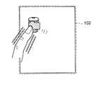
図1は、本発明の第1実施形態に係るPDA10の外観を例示する斜視図である。同図において、本体ケース101の開口部に臨む液晶表示パネル103aの表示画面上には、透明のタッチパネル102が重ねられている。ユーザは、このタッチパネル102に指先でタッチすることにより、PDA10に対する操作指令を入力する。なお、タッチパネル102に対するタッチ操作は、ペンなどの操作具を用いる形態であってもよい。また、本体ケース101の上面には、主電源のON/OFF操作など、PDA10に操作指令を入力するための押下式の操作キー104a,104b,104cが設けられている。
【0059】
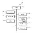
次に、図2は、図1に示したPDA10のハードウェア構成を例示するブロック図である。同図に示すように、PDA10は、タッチパネル102、表示部103、キー入力部111、メモリ112、CPU(Central Processing Unit)113、駆動信号生成回路114および振動アクチュエータ115を有する。
【0060】
タッチパネル102は、タッチ操作に応じてタッチパネル102上のタッチ位置を示す信号(以下、タッチ信号と述べる)をCPU113に出力する。また、表示部103は、液晶表示パネル103aと、この液晶表示パネル103aの表示制御を行う駆動回路とを有する。キー入力部111は、ユーザによる操作キー104a〜104cの押下操作に応じたキー操作信号をCPU113に出力する。メモリ112には、PDA10を制御するためのプログラムやデータなどが格納されている。また、このメモリ112には、振動アクチュエータ115を駆動するための駆動信号の波形データが格納されている。
【0061】
CPU113は、メモリ112に格納されているプログラムを実行することによりバス116を介して接続されている装置各部を制御する。このCPU113は、振動制御処理1(図5参照)を実行し、タッチパネル102や操作キー104a〜104cからの操作入力を検知した場合に、駆動信号生成回路114を介して振動アクチュエータ115を駆動してタッチパネル102や操作キー104a〜104cを振動させる。
【0062】
駆動信号生成回路114は、CPU113から供給される波形データに従って振動アクチュエータ115を駆動するための駆動信号を生成する。また、この駆動信号生成回路114は、CPU113からの指示に従って振動アクチュエータ115に駆動信号を印加する。
【0063】
振動アクチュエータ115は、永久磁石を可動錘(錘体)として用いており、電磁力により可動錘に直線的な往復運動を行わせて振動を発生させる、いわゆる永久磁石可動型のリニア振動アクチュエータ(Linear Oscillatory Actuator)である。この振動アクチュエータ115は、駆動信号生成回路114から印加される駆動信号によって駆動され、振動を発生する。
【0064】
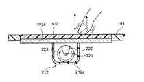
図3は、PDA10の本体ケース101内における振動アクチュエータ115の設置状態を模式的に例示する断面図である。同図に示すように、振動アクチュエータ115のケース115a上面は、液晶表示パネル103aと操作キー104a〜104cとに接している。また、振動アクチュエータ115のケース115a内部には、ケース115a上面に固定された円筒状のコイル121と、永久磁石により形成された、コイル121が収まる円環状の隙間を有する円柱状の可動錘122と、可動錘122を支持するスプリング123と、が設けられている。
【0065】
なお、振動アクチュエータ115のケース115aは、密閉されており、磁気シールドとして機能する。このような磁気シールドとしての機能をケース115aに持たせるためには、例えば、ケース115aを導電性物質で形成して接地または同電位とすること、あるいは、ケース115aを透磁率の大きい磁性体で形成すればよい。
【0066】
可動錘122は、振動アクチュエータ115のケース115a内部に形成された空間に、図中、上下方向に直線的な往復運動が可能な状態で、スプリング123により支持されている。このスプリング123は、図3に示すように、一方の端が、液晶表示パネル103aと操作キー104a〜104cに接するケース115a(ベース部材)につなげられており、他方の端が可動錘122につなげられている。なお、スプリング123は、複数設けられている構成であってもよい。また、スプリング123の代わりに、例えば、ひも状のゴムなど、弾性体を用いて構成された支持部材を使用してもよい。
【0067】
可動錘122は、コイル121に対して交流電流(駆動信号)が印加されると、このコイル121から発生する磁力により、図中、上下方向に直線的な往復運動を行う。この可動錘122の往復運動の反力として、スプリング123がつなげられたケース115a部分に振動加速度が生じる。なお、スプリング123がつなげられたケース115a部分には、可動錘122の往復運動に伴い、この往復運動の反力の他に、可動錘122からスプリング123を介して伝わる振動成分が加わるが、この振動アクチュエータ115における振動発生原理の基本は、可動錘122の往復運動の反力として生じた振動加速度を用いることにある。
【0068】
この振動加速度により液晶表示パネル103aと操作キー104a〜104cに振動が伝わる。この振動の方向は、タッチパネル102の表面に対して垂直となる方向であり、ユーザがタッチパネル102や操作キー104a〜104cを押す方向およびその反対方向と一致する。これにより、タッチパネル102および操作キー104a〜104cがタッチパネル102の表面に対して垂直となる方向に振動し、操作入力を行っているユーザの指先に振動が伝わる。
【0069】
なお、図3に示した振動アクチュエータ115は、防磁効果を有するケース115aで密閉されているが、このようなケース115aで密閉されていなくてもよい。また、可動錘112を支持するスプリング123は、ケース115aではなく、直接、液晶表示パネル103の裏面などにつながれていてもよい。
【0070】
ところで、このように1パッケージ化された振動アクチュエータ115を用いることには、以下の利点がある。すなわち、1パッケージ化されていない振動アクチュエータを用いる場合、例えば、タッチパネルが重ねられた液晶表示パネルの裏面と、この液晶表示パネルを支持する電子機器の本体装置との双方に、振動アクチュエータの部材を分離設置しなければならない。例えば、液晶表示パネルの裏面に永久磁石を設置するとともに、電子機器の本体装置側において永久磁石と対向する位置にコイルを設置する必要がある。
【0071】
このような場合、分離設置した部材の取り付け精度が悪いと、あるいは経年変化により部材の取り付け精度が悪化すると、これが即座にタッチパネルの振動の不具合として表面化してしまい、安定した精度でタッチパネルを振動させることが困難である。また、部品点数が多いことや永久磁石とコイルの位置合わせなど、電子機器の組み立て作業の工程が煩雑化してその分だけ製品コストが高くついてしまう。
【0072】
さらに、このような離設置を行う場合、タッチパネルを効率良く振動させるためには、液晶表示パネルを支持する電子機器の本体装置や筐体などの支持体が確実に固定されているか、あるいは支持体の質量が液晶表示パネルに対して十分に大きくなければならない。したがって、振動アクチュエータの分離設置は、軽量の電子機器や携帯型電子機器には適さない。
【0073】
これに対して1パッケージ化された振動アクチュエータ115を用いた場合、あらかじめケース115a内に可動錘122(永久磁石)とコイル121が収容されているので、永久磁石とコイルの取り付け精度の良し悪しがほとんど生じない。また、分離設置を行った場合と比較して経年変化による永久磁石とコイルの設置精度の悪化も生じにくい。したがって、安定した精度でタッチパネル102を振動させることができる。また、液晶表示パネル103aの裏面など、振動させたい部材に対して1パッケージ化された振動アクチュエータ115を取り付けるだけで良く、電子機器の組み立て作業の工程を簡素化できる。
【0074】
さらに、振動アクチュエータ115は、空中に支持された可動錘122に往復運動を行わせることにより当該往復運動の反力として生じる振動を、可動錘122がつながれている液晶表示パネル103aなどに与える。したがって、PDA10の本体装置や本体ケース101などの支持体が確実に固定されていない場合や、支持体の質量が液晶表示パネル103aに対して十分に大きくない場合であっても、振動アクチュエータ115は、十分な大きさの振動を液晶表示パネル103aなどに与えることができる。これは、特に、軽量の電子機器や携帯型の電子機器に用いた場合に好適である。
【0075】
なお、この振動アクチュエータ115のコイル121に可聴帯域の音声信号を印加すると、例えば、振動アクチュエータ115のケース115aや、当該振動アクチュエータ115が設置されたPDA10の本体ケース101などを振動させて、音声信号に応じた音を発生させることができる。つまり、振動アクチュエータ115を発音源としても利用することができる。この場合、音声信号の印加に応じて振動アクチュエータ115から発生する振動が伝わる、例えば、液晶表示パネル103aや本体ケース101などを音響拡声機構として用い、振動アクチュエータ115から発生させた音の大きさを増幅させる構成とすることが好適である。このように振動発生器と発音源を兼用することができると、例えば、携帯電話機やページャなどの小型電子機器において、構成部品の設置スペースを大幅に節約できる。なお、振動アクチュエータ115に発音源としての機能を持たせる場合、振動アクチュエータ115の内部または外部に、例えば、コーン紙やホーンなどの音響拡声機構を具備する構成としてもよい。
【0076】
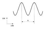
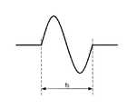
次に、図4は、振動アクチュエータ115に印加される駆動信号の波形を例示する図である。同図において、振動アクチュエータ115のコイル121に印加される駆動信号の周波数f0は、PDA10の本体ケース101の固有振動数f1、あるいは振動アクチュエータ115自身の固有振動数f2と一致させている。このような周波数f0の駆動信号をコイル121に印加すると、PDA10の本体ケース101あるいは振動アクチュエータ115が共振するので、少ない駆動電力でより大きな振動をユーザに与えることができる。つまり、PDA10の電力消費を節約することができる。このような周波数データや、振幅データなどが駆動信号の波形データとしてメモリ112に格納されている。
【0077】
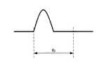
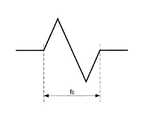
なお、駆動信号の周波数f0は、この周波数f0を整数倍した値が固有振動数f1あるいは固有振動数f2と一致するように定められていてもよい。このような周波数f0であっても、PDA10の本体ケース101あるいは振動アクチュエータ115を共振させることができる。また、駆動信号の波形は、図4に例示したSIN波に限定されるものではなく、方形波、台形波、三角波などであってもよいことは勿論である。
【0078】
[A−2.第1実施形態の動作]
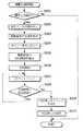
図5は、本実施形態に係るPDA10において、CPU113により実行される振動制御処理1の動作を説明するフローチャートである。この振動制御処理1は、タッチパネル102や操作キー104a〜104cに対する操作入力が許可されている期間において、CPU113により所定周期毎に実行される。
【0079】
同図に示すように、まず、CPU113は、タッチパネル102からタッチ信号が入力されたか否か、およびキー入力部111からキー操作信号が入力されたか否かを判別する(ステップS101)。CPU113は、タッチ信号およびキー操作信号がともに入力されていないと判別した場合は、振動制御処理1を終了する。一方、CPU113は、タッチ信号あるいはキー操作信号のいずれか一方以上が入力されたと判別した場合は、まず、振動アクチュエータ115に印加する駆動信号の波形データをメモリ112から読み出す(ステップS102)。
【0080】
なお、CPU113は、上記ステップS101において、タッチパネル102からタッチ信号が入力されたと判別した場合であっても、この信号に基づくタッチパネル102上のタッチ位置が、例えば、表示画面に表示されているタッチボタンの表示領域から外れていると検知した場合には、ステップS102の処理に移行せず、振動制御処理1を終了する。
【0081】
次いで、CPU113は、メモリ112から読み出した波形データを駆動信号生成回路114に出力する。また、これと同時にCPU113は、駆動信号生成回路114に対して駆動信号の生成を指示する(ステップS103)。このステップS103の処理により、駆動信号生成回路114は、CPU113から供給された波形データを用いて駆動信号を生成する。
【0082】
次いで、CPU113は、駆動信号の印加時間を計時するためのカウント値をリセットする(ステップS104)。そして、CPU113は、駆動信号の印加開始を駆動信号生成回路114へ指示する(ステップS105)。また、これと同時にCPU113は、印加時間の計時を開始する(ステップS106)。駆動信号生成回路114は、CPU113から印加開始が指示されると、この後、CPU113から印加停止が指示されるまでの期間、駆動信号を振動アクチュエータ115に印加する。これにより、振動アクチュエータ115が駆動し、タッチパネル102および操作キー104a〜104cがタッチパネル102の表面に対して垂直となる方向に振動する。
【0083】
また、CPU113は、印加時間の計時開始に応じて、印加時間計時用のカウント値をカウントアップする(ステップS107)。そして、CPU113は、カウント値があらかじめ設定された規定時間に相当するカウント値に達したか否かを判別する(ステップS108)。例えば、本実施形態においては、規定時間が0.5秒に定められている。
【0084】
CPU113は、印加時間が規定時間以下である場合は、上記ステップS107に戻って印加時間のカウントアップを行う。また、CPU113は、印加時間が規定時間を超えたと判別した場合、すなわち、印加時間が0.5秒に達した場合は、駆動信号生成回路114に対して駆動信号の印加停止を指示する(ステップS109)。この後、CPU113は、振動制御処理1を終了する。駆動信号生成回路114は、CPU113から印加停止が指示されると、振動アクチュエータ115への駆動信号の印加を停止する。
【0085】
以上説明したように本実施形態によれば、CPU113は、タッチパネル102や操作キー104a〜104cに対する操作入力を検知した場合に、振動アクチュエータ115を駆動し、タッチパネル102や操作キー104a〜104cを振動させる。したがって、PDA10は、操作入力が受付けられたことを振動によりユーザへ報知することができる。その結果、ユーザは、画面表示を見なくても、タッチパネル102や操作キー104a〜104cに対する操作入力がPDA10に受付けられたか否かを確認することができる。
【0086】
また、振動アクチュエータ115としてリニア振動アクチュエータを用いているので、この振動アクチュエータ115から発生させる振動の方向精度が高い。したがって、振動方向をタッチパネル102の表面や操作キー104a〜104cの押下方向に対して垂直となるように振動アクチュエータ115をPDA10に組み込むことで、タッチパネル102に対してタッチ操作が行われた場合や、薄型の操作キー104a〜104cの押下操作が行われた場合に、例えば、タッチボタンや操作キーの押し込み感を振動刺激によりユーザに与えることができる。
【0087】
また、振動アクチュエータ115のコイル121に可聴帯域の音声信号を印加することで、この振動アクチュエータ115を発音源としても利用することができる。
【0088】
さらに、振動時間を0.5秒など短時間にすることにより、例えば、タッチパネル102や操作キー104a〜104cが操作された時に、いわゆるクリック感と同様の操作感覚を振動刺激によりユーザに与えることができる。ここで、クリック感とは、例えば、ディスプレイに画面表示されているアイコンやボタンをマウスを操作して選択する際に、マウスのボタンを押し込んで離す動作を行ったときに生じる操作感覚である。このようなクリック感を与えるためには、振動時間が最大でも1秒以下であることが好ましい。また、このように振動時間を短時間とすることで、振動アクチュエータ115の駆動電力を低減し、PDA10の消費電力を節約することができる。
【0089】
また、振動アクチュエータ115は、磁気シールドとして密閉されたケース115a内にコイル121と可動錘122とを収容している。したがって、振動アクチュエータ115は、その周囲に設置されたPDA10の構成部品から磁力の影響を受けない。また、振動アクチュエータ115は、周囲の構成部品に対してコイル121から発生する磁力の影響を与えない。
【0090】
振動アクチュエータ115が、周囲の構成部品から磁力の影響を受けないようにすることは、可動錘122の往復運動の方向精度、すなわち、振動アクチュエータ115から発生させる振動の方向精度を一定に保つ点において重要である。なぜならば、周囲の構成部品からの磁力の影響により振動アクチュエータ115から発生する振動の方向がズレてしまうと、上述したタッチボタンや操作キーの押し込み感を振動刺激によりユーザに与えることができなくなってしまう。
【0091】
また、振動アクチュエータ115が、その周囲の構成部品に対して磁力の影響を与えないようにすることは、周囲の構成部品の誤動作を防ぐ点において重要である。本実施形態では、液晶表示パネル103aを用いた場合について説明した。しかしながら、液晶表示パネル103aの代わりにCRT(Cathode-Ray Tube)を用いるような場合に、タッチパネル102を振動させるため、CRTの近傍に防磁効果を持たない振動アクチュエータを設置すると、この振動アクチュエータから発生する磁力の影響で、CRTの表示内容に変色やゆがみなどが生じてしまう可能性がある。
【0092】
なお、本実施形態においては、タッチパネル102や操作キー104a〜104cなどの操作部を振動させる構成、すなわち、操作入力を行ったユーザの指先に振動を与える場合について説明した。しかしながら、PDA10の本体ケース101を振動させる構成、すなわち、操作入力を行った指先ではなく、PDA10を把持するユーザの手に振動を与えるようにしてもよい。
【0093】
[B.第2実施形態]
本実施形態では、DCモータを使用したバイブレータを振動発生器として用いた場合について説明する。なお、本実施形態において、上記第1実施形態と共通する部分については同一の符号を使用するものとする。また、第1実施形態と共通する部分についてはその説明を省略するものとする。
【0094】
[B−1.第2実施形態の構成]
図6は、本実施形態に係るPDA20のハードウェア構成を例示するブロック図である。同図に示すように、PDA20は、タッチパネル102、表示部103、キー入力部111、メモリ112、CPU113、駆動信号生成回路211、バイブレータ212およびエンコーダ213を有する。
【0095】
メモリ112には、バイブレータ212を駆動するための駆動電圧の波形データが格納されている。CPU113は、振動制御処理2(図11参照)を実行し、タッチパネル102や操作キー104a〜104cからの操作入力を検知した場合に、駆動信号生成回路211を介してバイブレータ212を駆動してタッチパネル102や操作キー104a〜104cを振動させる。また、CPU113は、エンコーダ213から供給される回転角情報に基づいて、バイブレータ212に対する駆動信号の印加停止タイミングを決定する。
【0096】
駆動信号生成回路211は、CPU113から供給される波形データに従ってバイブレータ212を駆動するための駆動信号を生成する。また、この駆動信号生成回路211は、CPU113からの指示に従ってバイブレータ212に駆動信号を印加する。また、バイブレータ212は、回転軸に偏心錘を取り付けたDCモータである。このバイブレータ212は、駆動信号生成回路211から印加される駆動信号によって駆動され、振動を発生する。
【0097】
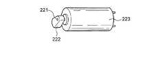
図7は、PDA20の本体ケース101内におけるバイブレータ212の設置状態を模式的に例示する断面図である。また、図8は、バイブレータ212の外観を例示する斜視図である。図7に示すように、液晶表示パネル103aの下面には、ケース212aに収容されたバイブレータ212が設置されている。このバイブレータ212は、図示を省略した支持部材によりケース212a内に固定されている。また、図7および図8に示すように、バイブレータ212は、回転軸221の先端に偏心錘222を取り付けたDCモータ223により構成されている。
【0098】
このDCモータ223に対して駆動電圧(駆動信号)が印加されると、回転軸221に取り付けられた偏心錘222が回転し、この偏心錘222の回転運動によりケース212aに振動が発生する。なお、バイブレータ212を使用した場合、上記第1実施形態において説明した振動アクチュエータ115の場合とは異なり、バイブレータ212から発生する振動の方向やその振動形態が、偏心錘222の初期位置やDCモータ223の回転方向などで異なってしまう。バイブレータ212から毎回、同じ振動を発生させるためには、偏心錘222の位置を検知し、偏心錘222をいつも同じ位置から同方向に回転させる必要がある。
【0099】
このため、図6に示したように本実施形態に係るPDA20には、エンコーダ213が具備されている。このエンコーダ213は、DCモータ223の回転角情報を検知してCPU113に出力する。CPU113は、エンコーダ213から供給される回転角情報に基づいて、DCモータ223に対する駆動電圧の印加停止タイミングを決定する。例えば、本実施形態では、図7に示すように、回転軸221を中心とした時、ちょうど12時の位置で偏心錘222が停止するように、DCモータ223に対する駆動電圧の印加停止タイミングが決定される。なお、DCモータ223の代わりにステッピングモータを使用した場合は、エンコーダ213を用いることなく回転軸に取り付けた偏心錘の位置を検知することが可能である。
【0100】
以上説明したように偏心錘222の停止位置を制御することで、バイブレータ212から発生する振動の方向を、タッチパネル102の表面に対して垂直となる方向と一致させることができる。バイブレータ212から発生した振動は、液晶表示パネル103aを介してタッチパネル102に伝わる。これにより、タッチパネル102がその表面に対して垂直となる方向に振動し、この振動がタッチパネル102を操作しているユーザの指先に伝わる。
【0101】
次に、図9は、バイブレータ212に印加される駆動電圧の波形について例示する図である。また、図10は、タッチパネル102の表面に生じる振動について例示する図である。バイブレータ212の場合、印加される駆動電圧に応じてDCモータ223の回転数が変化する。ここで、DCモータ223の回転数が、PDA20の本体ケース101の固有振動数f1、あるいはバイブレータ212の固有振動数f3と一致すると、PDA20の本体ケース101あるいはバイブレータ212が共振する。
【0102】
そこで、本実施形態では、DCモータ223の回転数を、固有振動数f1あるいは固有振動数f3と一致させる駆動電圧をバイブレータ212に印加する。したがって、図10に示すように、タッチパネル102は、固有振動数f1あるいは固有振動数f3の周期でその表面に対して垂直となる方向に振動する。これにより、少ない駆動電力でより大きな振動を与えることが可能となり、PDA20の電力消費を節約することができる。なお、駆動電圧の波形は、図9に例示した方形波に限定されるものではない。
【0103】
[B−2.第2実施形態の動作]
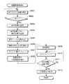
図11は、本実施形態に係るPDA20において、CPU113により実行される振動制御処理2の動作を説明するフローチャートである。この振動制御処理2は、タッチパネル102や操作キー104a〜104cに対する操作入力が許可されている期間において、CPU113により所定周期毎に実行される。なお、この振動制御処理2のステップS201〜S208に示す処理は、上記第1実施形態で説明した振動制御処理1(図5参照)のステップS101〜S108の処理と同様であるので説明を省略する。
【0104】
但し、本実施形態においては、バイブレータ212を振動発生器として用いているため、駆動信号生成回路211において生成される駆動信号が、図9に示した駆動電圧となる。バイブレータ212は、この駆動電圧が印加されると、本体ケース101の固有振動数f1あるいはバイブレータ212の固有振動数f3と一致する回転数でDCモータ223を回転させる。これにより偏心錘222が回転し、振動を発生させる。このバイブレータ212から発生した振動により、タッチパネル102および操作キー104a〜104cがタッチパネル102の表面に対して垂直となる方向に振動する。
【0105】
そして、ステップS208においてCPU113は、印加時間が規定時間を超えたと判別した場合、すなわち、印加時間が0.5秒に達した場合にステップS209に移行する。次いで、CPU113は、エンコーダ213から供給される回転角情報に基づいて、偏心錘222を毎回同じ位置で停止させるための駆動電圧の印加停止タイミングを決定する(ステップS209)。本実施形態では、図7に示したように、回転軸221を中心とした時、ちょうど12時の位置で偏心錘222が停止するように駆動電圧の印加停止タイミングが決定される。
【0106】
次いで、CPU113は、決定した印加停止タイミングに従って駆動信号生成回路211へ駆動信号の印加停止を指示する(ステップS210)。この後、CPU113は、振動制御処理2を終了する。駆動信号生成回路211は、CPU113から印加停止が指示されると、バイブレータ212への駆動信号の印加を停止する。これによりバイブレータ212のDCモータ223に取り付けられた偏心錘222は、毎回、同じ位置で停止する。このように偏心錘222をいつも同じ位置で停止させ、かつ、この偏心錘222を同じ停止位置から同方向に回転させることで、バイブレータ212から発生させる振動の方向を固定することができる。また、バイブレータ212から発生させる振動を、より木目細やかに制御することが可能となる。
【0107】
以上説明したように本実施形態によれば、CPU113は、タッチパネル102や操作キー104a〜104cに対する操作入力を検知した場合に、バイブレータ212を駆動し、タッチパネル102や操作キー104a〜104cを振動させる。したがって、PDA20は、操作入力が受付けられたことを振動によりユーザへ報知することができる。
【0108】
また、本実施形態では、偏心錘222をいつも同じ位置で停止させ、当該停止位置から同方向に回転を開始させるようにした。これにより、バイブレータ212から発生する振動の方向を固定することができるとともに、バイブレータ212から発生させる振動を、より木目細やかに制御することができる。以上のようなことから、タッチパネル102に対してタッチ操作が行われた場合や、薄型の操作キー104a〜104cの押下操作が行われた場合に、タッチボタンや操作キーの押し込み感、クリック感を振動刺激によりユーザに与えることができる。このような押し込み感やクリック感の付与は、上述した偏心錘222の停止位置の制御を行わなければ達成し得ないことであり、従来の偏心錘付きモータでは実現できなかったことである。
【0109】
[C.第3実施形態]
本実施形態では、操作入力によって指示された処理の実行が終了した場合に、この処理の実行終了を振動により報知する携帯型電子機器について説明する。なお、本実施形態において、上記第1実施形態と共通する部分については同一の符号を使用するものとする。また、第1実施形態と共通する部分についてはその説明を省略するものとする。
【0110】
[C−1.第3実施形態の構成]
図12は、本実施形態に係るPDA30の外観を例示する斜視図である。同図において、PDA30には、本体ケース301の開口部に臨んで液晶表示パネル302aの表示画面が設けられている。また、本体ケース301の上面には、押下式の操作キーを複数有するキー入力部303が設けられている。
【0111】
図13は、図12に示したPDA30のハードウェア構成を例示するブロック図である。同図に示すように、PDA30は、表示部302、キー入力部303、無線通信部304、メモリ112、CPU113、駆動信号生成回路114および振動アクチュエータ115を有する。
【0112】
このPDA30は、WAN(Wide Area Network)やLAN(Local Area Network)などのネットワークを介して他の通信装置とデータ通信を行う機能を有している。無線通信部304は、WANやLANの無線基地局との間で行われる無線通信を制御する。また、CPU113は、振動制御処理3(図14参照)を実行し、操作入力によって指示された処理の実行が終了したことを検知した場合に、駆動信号生成回路114を介して振動アクチュエータ115を駆動して本体ケース301を振動させる。
【0113】
なお、振動アクチュエータ115は、上記第1実施形態で説明した振動アクチュエータ115と同じものである。但し、本実施形態において、振動アクチュエータ115は、PDA30の背面側、すなわち、表示画面が設けられた面とは反対側の本体ケース301内側に取り付けられ、本体ケース301を振動させる。そして、この振動がPDA30を把持しているユーザの手に伝わる。
【0114】
[C−2.第3実施形態の動作]
図14は、本実施形態に係るPDA30において、CPU113により実行される振動制御処理3の動作を説明するフローチャートである。この振動制御処理3は、待ち時間を要する処理の実行が操作入力により指示された場合に実行される。ここで、待ち時間を要する処理とは、例えば、webページの読み込み処理などのファイルデータのダウンロードやアップロード、自己当ての電子メールの有無を確認するメールチェック処理、アプリケーションソフトの起動処理、ファイルデータのコピーや一括削除、メモリ112内のデータ格納領域の初期化処理などである。
【0115】
同図に示すように、まず、CPU113は、操作入力によって指示された処理を実行する(ステップS301)。次いで、CPU113は、実行中の処理が終了したか否かを判別する(ステップS302)。処理が終了していない場合、CPU113は、上記ステップS301に戻り、処理の実行を継続する。また、CPU113は、上記ステップS302において実行中の処理が終了したと判別した場合は、ステップS303に移行する。このステップS303以降の処理は、上記第1実施形態で説明した振動制御処理1(図5参照)のステップS102以降の処理と同様であるので説明を省略する。
【0116】
このような制御構成とすることで、CPU113は、操作入力によって指示された処理の実行が終了したことを検知すると、駆動信号生成回路114を介して振動アクチュエータ115を駆動し、PDA30の本体ケース301を振動させる。これにより、PDA30を把持するユーザの手に振動が伝わる。
【0117】
ところで、例えば、メールチェック処理の実行終了を振動により報知する場合、自己当ての電子メールがあった場合と、なかった場合とに応じて振動の形態を異ならせることが有効である。このように、実行された処理の結果に応じて振動の形態を異ならせる制御方法について以下に説明する。
【0118】
図15は、本実施形態に係るPDA30において、CPU113により実行される振動制御処理4の動作を説明するフローチャートである。同図に示すように、まず、CPU113は、操作入力によって指示された処理を実行する(ステップS401)。そして、CPU113は、実行中の処理が終了したと判別した場合に(ステップS402)、ステップS403に移行する。
【0119】
次いで、CPU113は、上記ステップS401において実行された処理の実行結果を取得する(ステップS403)。CPU113は、この実行結果に応じて、駆動信号の印加時間、すなわち、印加時間を定める規定時間のカウント値を変更する(ステップS404)。例えば、メールチェック処理が実行された場合、CPU113は、チェック結果に応じて、自己当ての電子メールがなかった場合は規定時間を0.5秒のままとする。また、自己当ての電子メールがあった場合は規定時間を1.5秒に変更する。
【0120】
なお、ステップS405以降の処理は、上述した振動制御処理3(図14参照)のステップS303以降の処理と同様であるので詳細な説明を省略するが、CPU113は、処理の実行結果に応じて本体ケース301の振動時間を異ならせる。
【0121】
以上説明したように本実施形態によれば、CPU113は、操作入力によって指示された処理が終了したことを検知した場合に、振動アクチュエータ115を駆動し、PDA30の本体ケース301を振動させる。したがって、PDA30は、操作入力によって指示された処理の実行終了を、振動によりユーザへ報知することができる。また、本実施形態によれば、CPU113は、処理の実行結果に応じて振動アクチュエータ115の振動時間を異ならせる。したがって、ユーザは、画面情報を見なくても、指示した処理の実行結果を振動時間により認識することができる。
【0122】
なお、本実施形態では、処理の実行結果に応じて振動時間を変更する場合について説明したが、振動の大きさや振動の回数などを変更してもよい。要は、処理の実行結果に応じて振動アクチュエータ115から発生させる振動の形態を異ならせればよい。また、本実施形態では、PDA30の本体ケース301全体を振動させる構成とした。しかしながら、本体ケース301のうち、ユーザがPDA30を把持する際に握る部分のみを振動させる構成としてもよい。
【0123】
また、本実施形態においては、PDA30の本体ケース301を振動させる構成、すなわち、PDA30を把持する手に振動を与える場合について説明した。しかしながら、PDA30に備わる複数の操作キーを振動させる構成、すなわち、操作入力を行った指先に振動を与えるようにしてもよい。
【0124】
[D.第4実施形態]
本実施形態では、携帯型電子機器がユーザに把持されているか否かに応じて、振動させる部位をタッチパネルまたは筐体の把持部に切り替える携帯型電子機器について説明する。なお、本実施形態において、上記第1実施形態と共通する部分については同一の符号を使用するものとする。また、第1実施形態と共通する部分についてはその説明を省略するものとする。
【0125】
[D−1.第4実施形態の構成]
図16は、本実施形態に係るPDA40の内部構造を例示する図である。同図において、PDA40は、タッチパネル102が重ねられた液晶表示パネル103aを有し、この液晶表示パネル103aの表示画面が本体ケース401の開口部に臨んでいる。また、この液晶表示パネル103aの裏面には、振動アクチュエータ115aが設けられている。この振動アクチュエータ115aは、タッチパネル102を振動させ、タッチ操作を行ったユーザの指先に振動を与える。
【0126】
一方、PDA40の背面側、すなわち、表示画面が設けられた面とは反対側の本体ケース401内側には、振動アクチュエータ115bが設けられている。この振動アクチュエータ115bは、PDA40を把持しているユーザの手のひらに本体ケース401を介して振動を与える。なお、各振動アクチュエータ115a,115bは、上記第1実施形態で説明した振動アクチュエータ115と同じものである。また、本体ケース401の側面には、主電源のON/OFF操作などを入力する押下式の操作キー104aが設けられている。
【0127】
このようにPDA40は、2つの振動アクチュエータ115a,115bを有する。また、図16においては図示を省略しているが、PDA40はタッチセンサを有し、PDA40がユーザに把持されているか否かに応じて、いずれか一方の振動アクチュエータを駆動して振動を発生させる。このような制御を行う理由は、例えば、卓上に置かれたPDA40の本体ケース401を振動させると、その振動でPDA40が移動してしまう、あるいは振動時に卓と当たることで不快な振動音が生じてしまうなどといったことを防ぐためである。
【0128】
なお、本実施形態では、制御の一例として、PDA40がユーザに把持されている場合には、振動アクチュエータ115bのみを駆動してPDA40を把持しているユーザの手のひらに振動を与える一方、PDA40がユーザに把持されていない場合には、振動アクチュエータ115aのみを駆動してタッチ操作を行った指先に振動を与える場合について説明する。但し、例えば、PDA40がユーザに把持されている場合に、両方の振動アクチュエータ115a,115bを駆動して振動報知を行う構成としてもよい。
【0129】
図17は、図16に示したPDA40のハードウェア構成を例示するブロック図である。同図に示すように、PDA40は、PDA40は、タッチパネル102、表示部103、キー入力部111、メモリ112、CPU113、駆動信号生成回路114、振動アクチュエータ115a,115bおよびタッチセンサ411を有する。
【0130】
タッチセンサ411は、PDA40がユーザに把持されているか否かを検知するセンサであり、検知結果をCPU113に供給する。
メモリ112には、振動アクチュエータ115a,115bに印加する駆動信号の波形データが格納されている。ここで、振動アクチュエータ115aに印加する駆動信号の周波数は、タッチパネル102を具備した液晶表示パネル103aを共振させる周波数、あるいは振動アクチュエータ115a自身を共振させる周波数と一致させている。また、振動アクチュエータ115bに印加する駆動信号の周波数は、PDA40の本体ケース401を共振させる周波数、あるいは振動アクチュエータ115b自身を共振させる周波数と一致させている。
【0131】
CPU113は、振動制御処理5(図18参照)を実行し、タッチパネル102に対するタッチ操作が受付けられたことを振動によりユーザへ報知する。但し、本実施形態においてCPU113は、タッチセンサ411の検出結果に応じて、2つの振動アクチュエータ115a,115bのうちいずれか一方のみを駆動して振動を発生させる。
【0132】
駆動信号生成回路114は、CPU113から供給される波形データに従って振動アクチュエータ115a,115bを駆動するための駆動信号を生成する。また、この駆動信号生成回路114は、CPU113からの指示に従って振動アクチュエータ115a,115bに駆動信号を印加する。
【0133】
[D−2.第4実施形態の動作]
図18は、本実施形態に係るPDA40において、CPU113により実行される振動制御処理5の動作を説明するフローチャートである。この振動制御処理5は、タッチパネル102に対するタッチ操作が許可されている期間において、CPU113により所定周期毎に実行される。
【0134】
同図に示すように、まず、CPU113は、タッチパネル102からタッチ信号が入力されたか否かを判別する(ステップS501)。CPU113は、タッチ信号が入力されていないと判別した場合は、振動制御処理5を終了する。なお、CPU113は、タッチパネル102からタッチ信号が入力されたと判別した場合であっても、この信号に基づいて検出されるタッチパネル102上のタッチ位置が、例えば、表示画面に表示されているタッチボタンの表示領域から外れていると検知した場合には、ステップS502の処理に移行せず、振動制御処理5を終了する。
【0135】
一方、CPU113は、上記ステップS501においてタッチ信号が入力されたと判別した場合は、次いで、PDA40がユーザに把持されているか否かをタッチセンサ411の検知結果に基づいて判別する(ステップS502)。そして、CPU113は、PDA40がユーザに把持されていると判別した場合は、駆動する振動アクチュエータを振動アクチュエータ115bに決定する(ステップS503)。すなわち、PDA40がユーザに把持されている場合は、本体ケース401の把持部を振動させ、PDA40を把持しているユーザの手のひらに振動を与える。
【0136】
一方、CPU113は、上記ステップS502においてPDA40がユーザに把持されていないと判別した場合は、駆動する振動アクチュエータを振動アクチュエータ115aに決定する(ステップS504)。すなわち、PDA40がユーザに把持されいない場合は、タッチパネル102を振動させ、タッチ操作を行ったユーザの指先に振動を与える。
【0137】
なお、ステップS505以降の処理は、上記第1実施形態で説明した振動制御処理1(図5参照)のステップS102以降の処理と同様であるので詳細な説明を省略するが、CPU113は、上記ステップS503またはS504の処理により決定した振動アクチュエータを駆動して、タッチパネル102または本体ケース401の把持部に振動を与える。
【0138】
以上説明したように本実施形態によれば、CPU113は、タッチセンサ411の検知結果に応じていずれか一方の振動アクチュエータを駆動し、振動を発生させる。したがって、PDA40は、当該PDA40がユーザに把持されているか否かに応じて、振動させる部位をタッチパネル102または本体ケース401の把持部に変更することができる。
【0139】
なお、本実施形態において、振動報知時に使用する振動アクチュエータをユーザが指定可能な構成としてもよい。この場合、CPU113は、振動報知時に使用する1以上の振動アクチュエータをユーザに指定させるための画面表示を行う。CPU113は、ユーザからの操作入力により、使用する振動アクチュエータが指定されると、その指定情報をメモリ112に記憶する。そして、CPU113は、上記ステップS501においてタッチパネル102からタッチ信号が入力されたと判別した後、メモリ112に記憶された指定情報に従って、駆動する振動アクチュエータを決定する。
【0140】
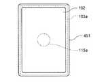
また、図19は、本実施形態の変形例に係るPDA41の内部構造を例示する断面図である。同図において、その表示面にタッチパネル102が重ねられ、かつ、裏面に振動アクチュエータ115aが設置された液晶表示パネル103aは、弾性部材451を介してPDA41の本体ケース401に取り付けられている。この弾性部材451は、例えば、ゴムやウレタン、スポンジなどであって、図20に示すように、液晶表示パネル103aの周縁部に取り付けられている。この弾性部材451は、タッチパネル102および液晶表示パネル103aを効率的に振動させるための部材である。
【0141】
なお、この弾性部材451は、図21や図22に示すように、液晶表示パネル103aの周縁部に複数個に分けて設置されるものであってもよい。また、この弾性部材451は、スプリングなどを用いて構成されるものであってもよい。これらの図20〜図22に示した弾性部材451,451a〜451fを介してタッチパネル102および液晶表示パネル103aを本体ケース401に取り付ける構成とすることで、振動アクチュエータ115a,115bから発生させた振動を効率的にタッチパネル102および液晶表示パネル103aに与えることができる。したがって、振動アクチュエータ115aの駆動電力を抑えつつ、より大きな振動をユーザへ与えることができる。
【0142】
また、図23に示すように、タッチパネル102が重ねられた液晶表示パネル103aの裏面と、PDA42の背面側の本体ケース401内側と、の両方に接するように振動アクチュエータ115cを設置する構成としてもよい。このような構成とした場合、タッチパネル102に対してタッチ操作を行った指先と、PDA42を把持する手に同一の振動を与えることができる。
【0143】
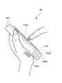
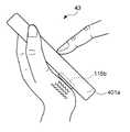
さらに、図24に示すように、振動アクチュエータ115bは、本体ケース401aに設けられた開口部からその一部を外部に露出するように設置され、PDA43を把持するユーザの手のひらに直接、振動を与える構成であってもよい。このような構成とした場合も、振動アクチュエータ115bから発生させた振動を効率的にユーザへ与えることができる。また、このような場合、振動アクチュエータ115bは、直接、ユーザに振動を与えることができるので、より細やかな振動の制御を行うことができる。
【0144】
[E.第5実施形態]
本実施形態では、タッチパネルを振動させる振動発生器の設置場所について説明する。
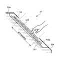
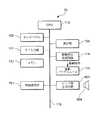
図25は、本実施形態に係るATM50の内部構造を説明するための断面図である。同図において、ATM50の本体装置50aの前面には、液晶表示パネル501が傾斜させて設置されている。この液晶表示パネル501の表示面上には、ダンパ503を介してタッチパネル502が取り付けられている。このタッチパネル502には、タッチ面の上方および下方に2つの振動アクチュエータ115a,115bが設置されている。そして、このタッチパネル502のさらに外側に、開口部を有する本体カバー504が設けられている。
【0145】
ここで、タッチパネル502は、例えば、ガラス基板などの透明かつ硬質の部材で構成されている。また、ダンパ503は、ゴムやウレタン、スポンジなどの振動吸収部材であり、タッチパネル502の周縁部に取り付けられている。このダンパ503は、タッチパネル502に設置された振動アクチュエータ115a,115bから発生する振動のうち、液晶表示パネル501に伝わる振動成分を吸収し、振動が液晶表示パネル501に伝わらないようにするための部材である。また、このダンパ503は、液晶表示パネル501に設置されたタッチパネル502を効率的に振動させるための役割も担っている。このため、ダンパ503は、ゴムなどの弾性体により構成されていることが望ましい。
【0146】
振動アクチュエータ115a,115bは、上記第1実施形態で説明した振動アクチュエータ115と同じものである。また、ダンパ503および振動アクチュエータ115a,115bは、液晶表示パネル501の表示画面領域の外側に設けられている。
【0147】
同図に示すように、液晶表示パネル501は、ATM50の本体装置50aに固定されている。これに対してタッチパネル502は、ダンパ503のみを介して液晶表示パネル501に取り付けられており、かつ、タッチパネル502と本体カバー504との間には隙間が設けられている。このため、タッチパネル502は、振動アクチュエータ115a,115bから発生する振動により、タッチパネル502の表面に対して垂直となる方向に振動する。
【0148】
なお、タッチパネル502に対するタッチ操作に応じて振動アクチュエータ115a,115bから振動を発生させる制御については、振動アクチュエータ115a,115bが複数である点を除いて、上記第1実施形態で説明した振動制御処理1(図5参照)と同様の制御を行えばよいので説明を省略する。また、本実施形態において振動アクチュエータ115a,115bに印加する駆動信号の周波数は、タッチパネル502を共振させる周波数、あるいは振動アクチュエータ115a,115b自身を共振させる周波数としている。
【0149】
以上説明したように本実施形態によれば、ATM50は、振動アクチュエータ115a,115bから発生した振動によりタッチパネル502のみを振動させることができる。液晶表示パネル501への振動は、ダンパ503により吸収される。したがって、液晶表示パネル501の画面表示内容がぶれないので、例えば、上記第1実施形態のように液晶表示パネルごとタッチパネルを振動させる場合と比較して、表示内容が見易い。
【0150】
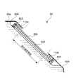
なお、図26に示すように、振動アクチュエータ115a,115bをタッチパネル502の液晶表示パネル501側に設置する構成としてもよい。また、図27は、本実施形態の変形例に係るATM51の内部構造を例示する断面図である。同図において、ATM51の本体装置50aの前面側に傾斜させて設置された液晶表示パネル501の表示面上には、2つの振動アクチュエータ115a,115bを介してタッチパネル502が取り付けられている。
【0151】
ここで、液晶表示パネル501はATM51の本体装置50aに固定されている。これに対してタッチパネル502は、振動アクチュエータ115a,115bのみを介して液晶表示パネル501に取り付けられており、かつ、タッチパネル502と本体カバー504との間には隙間が設けられている。このため、タッチパネル502は、振動アクチュエータ115a,115bから発生する振動により、タッチパネル502の表面に対して垂直となる方向に振動する。また、液晶表示パネル501は本体装置50aに固定されているため、振動アクチュエータ115a,115bと接しているものの、ほとんど振動しない。したがって、図27に示す構造としても、図25に示した構造の場合と同様の効果を得ることができる。
【0152】
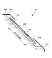
また、図28〜図31は、本実施形態のその他の変形例に係るATM52,53,54,55の内部構造を例示する断面図である。まず、図28に示すように、その表示面にタッチパネル502が重ねられ、かつ、裏面に振動アクチュエータ115a,115bが設置された液晶表示パネル501を、ダンパ503を介して本体カバー504に取り付ける構成としてもよい。この場合、液晶表示パネル501とATM52の本体装置50aとの間には隙間が設けられる。このような構成とすれば、振動アクチュエータ115a,115bから発生する振動により、タッチパネル502をその表面に対して垂直となる方向に振動させることができる。なお、この変形例におけるダンパ503は、タッチパネル502および液晶表示パネル501を効率的に振動させるための役割を担う。
【0153】
また、図29に示すように、その表示面にタッチパネル502が重ねられた液晶表示パネル501を、振動アクチュエータ115a,115bを介して本体カバー504に取り付ける構成としてもよい。この場合も、液晶表示パネル501とATM53の本体装置50aとの間に隙間が設けられる。このような構成であっても、図28に示した場合と同様に、振動アクチュエータ115a,115bから発生する振動によりタッチパネル502を振動させることができる。
【0154】
あるいは、図30に示すように、その表示面にタッチパネル502が重ねられ、かつ、裏面に振動アクチュエータ115a,115bが設置された液晶表示パネル501を、ダンパ503を介してATM54の本体装置50aに取り付ける構成としてもよい。この場合は、液晶表示パネル501と本体カバー504との間に隙間が設けられる。このような構成としても、振動アクチュエータ115a,115bから発生する振動により、タッチパネル502をその表面に対して垂直となる方向に振動させることができる。
【0155】
また、図31に示すように、その表示面にタッチパネル502が重ねられた液晶表示パネル501を、振動アクチュエータ115a,115bを介してATM55の本体装置50aに取り付ける構成としてもよい。この場合も、液晶表示パネル501と本体カバー504との間に隙間が設けられる。このような構成であっても、図30に示した場合と同様に、振動アクチュエータ115a,115bから発生する振動によりタッチパネル502を振動させることができる。
【0156】
これらの図28〜図31に示した各変形例は、いずれも液晶表示パネル501ごとタッチパネル502を振動させるものであるが、ATM52〜55は、タッチパネル502に対するタッチ操作を受付けたことを、タッチ操作を行ったユーザの指先に振動で報知することができる。
【0157】
なお、本実施形態では、ディスプレイとして液晶ディスプレイを用いた場合について説明した。しかしながらディスプレイは、CRTやプラズマディスプレイ、EL(Electronic Luminescence)ディスプレイなどであってもよい。また、振動アクチュエータ115a,115bの設置数は任意である。さらに、ダンパ503は、例えば、スプリングなどを用いて構成されるものであってもよい。
【0158】
[F.第6実施形態]
本実施形態では、操作入力が受付けられたことを、その操作入力の種類に応じて異なる形態の振動でユーザへ報知する電子機器について説明する。なお、本実施形態においては、上記第1実施形態で説明したPDA10を基礎として説明を行う。したがって、第1実施形態と共通する部分については同一の符号を使用するものとする。また、第1実施形態と共通する部分についてはその説明を省略するものとする。
【0159】
[F−1.第1例]
図32は、本実施形態の第1例に係るPDA10の画面表示例を示す図である。同図に示すように、PDA10の表示画面には、複数のタッチボタン「A」〜「G」が表示されている。画面表示されたこれらのタッチボタンにユーザが指先で触れることにより、表示画面上に重ねられたタッチパネル102がタッチ操作を検出する。なお、各タッチボタンに割り当てたアルファベットは、タッチボタンを識別するために付与したものにすぎない。
【0160】
次に、図33は、PDA10のメモリ112に格納されている波形データテーブル112aを例示する図である。同図に示すように、波形データテーブル112aには、画面表示される各タッチボタン毎に、このタッチボタンがタッチパネル102上において占有する領域をXY座標値を用いて示したエリアデータと、このタッチボタンが押された場合に振動アクチュエータ115に印加する駆動信号の波形データとが格納されている。
【0161】
ここで、各タッチボタンと対応付けられている駆動信号の波形は、例えば、図34〜図37に例示するように振幅や形状がそれぞれ異なる。但し、これらの各図において駆動信号の周波数f0は、PDA10の本体ケース101、タッチパネル102を具備した液晶表示パネル103a、振動アクチュエータ115のいずれかを共振させる周波数である。上述した波形データテーブル112aには、これらの駆動信号を生成するために必要となる周波数データや振幅データなどが波形データとして格納されている。
【0162】
このような構成を有するPDA10のタッチパネル102にユーザが指先でタッチすると、タッチパネル102は、タッチ操作を検出し、タッチ信号をCPU113に出力する。CPU113は、タッチ信号に基づいてタッチ位置のXY座標データを求め、波形データテーブル112aを参照して押されたタッチボタンを特定する。次いで、CPU113は、特定したタッチボタンに対応付けられた駆動信号の波形データを波形データテーブル112aから読み出す。
【0163】
そして、CPU113は、読み出した波形データを駆動信号生成回路114に出力する。また、これと同時にCPU113は、駆動信号生成回路114に対して駆動信号の生成を指示する。この後の処理は、上記第1実施形態で説明した振動制御処理1(図5参照)のステップS104以降の処理と同様であるので説明を省略する。
【0164】
以上説明したように本実施形態の第1例によれば、CPU113は、タッチパネル102に対するタッチ操作を検知した場合に、まず、タッチ位置を検出し、操作されたタッチボタンを特定する。そして、CPU113は、タッチボタンの種類に対応付けられた振動形態で振動アクチュエータ115から振動を発生させる。したがって、PDA10は、タッチ操作を受付けたことを報知する振動の形態を、操作されたタッチボタンに応じて異ならせることができる。
【0165】
なお、タッチパネル102上において、いずれのタッチボタンにも該当しない場所がユーザにより押された場合に、このタッチ操作が無効であることを示す振動を振動アクチュエータ115から発生させる構成としてもよい。また、振動時間や振動の回数などを変更して振動形態を異ならせる構成としてもよい。
【0166】
また、本実施形態の第1例に係る発明は、タッチパネル102の代わりに複数の操作キーを有する電子機器に対しても適用可能である。この場合、電子機器のメモリには、操作キー毎に波形データを記憶しておく。そして、電子機器の制御部は、操作キーが操作されたことを検知した場合に、操作されたキーに応じた波形データをメモリから読み出して振動発生器を駆動する。このような構成とすれば、キー操作が電子機器に受付けられたことを報知する振動の形態を、操作されたキーに応じて異ならせることができる。
【0167】
[F−2.第2例]
図38および図39は、PDA10の表示画面に表示されたアイコンをタッチパネル102に対するタッチ操作によりドラッグし、ゴミ箱に移す作業を行っている状態を例示する図である。なお、ここで言うゴミ箱とは、データの削除を指令するアイコンのことである。
【0168】
まず、ユーザがタッチパネル102に対するタッチ操作によりドラックしたいアイコンを選択すると、PDA10のCPU113は、タッチ位置を検出し、そのタッチ操作がアイコンの選択を指令したものであると特定する。PDA10のメモリ112には、図40に示すように、操作入力が指示する指令の種類毎に振動アクチュエータ115に印加する駆動信号の波形データが格納された波形データテーブル112bが記憶されている。
【0169】
CPU113は、この波形データテーブル112bから「アイコンの選択」に対応付けられた波形データを読み出して振動アクチュエータ115を駆動する。したがって、タッチ操作を行ったユーザの指先やPDA10を把持するユーザの手には、アイコンの選択が行われたことを示す振動が与えられる。
【0170】
また、図38に示すように、ユーザが指先をタッチパネル102に接触させたまま移動させ、選択したアイコンをドラッグしている場合、CPU113は、そのタッチ操作がアイコンのドラッグを指令したものであると特定する。したがって、CPU113は、波形データテーブル112bから「ドラッグ」に対応付けられた波形データを読み出して振動アクチュエータ115を駆動する。これにより、ユーザにはドラック中であることを示す振動が与えられる。例えば、ドラッグ中の場合には、弱めの振動を継続して与えることなどが好ましい。
【0171】
そして、図39に示すように、ドラッグされているアイコンがゴミ箱の上に重ねられると、CPU113は、タッチ操作がアイコンをゴミ箱に収容することを指令したものであると特定する。したがって、CPU113は、アイコンをゴミ箱に収容するとともに、波形データテーブル112bから「データの削除」に対応付けられた波形データを読み出して振動アクチュエータ115を駆動する。これにより、タッチ操作を行ったユーザには、アイコンを削除したことを示す振動が与えられる。
【0172】
以上説明したように本実施形態の第2例によれば、CPU113は、タッチパネル102に対するタッチ操作を検知した場合に、まず、タッチ操作が指示する指令の種類を特定する。そして、CPU113は、特定した指令の種類に対応付けられた振動形態で振動アクチュエータ115から振動を発生させる。したがって、PDA10は、タッチ操作を受付けたことを報知する振動の形態を、タッチ操作が指示する指令の種類に応じて異ならせることができる。
【0173】
[F−3.第3例]
図41は、本実施形態の第3例に係るPDA10の画面表示例を示す図である。同図に示すように、PDA10の表示画面には、例えば、PDA10の音量レベルや画面の明暗度などのパラメータ値を調整するための「目盛」と「つまみ」が表示されている。ユーザは、画面表示された「つまみ」の位置を、タッチパネル102に対するタッチ操作によりドラッグし、変更することができる。
【0174】
まず、ユーザがタッチパネル102に対するタッチ操作により「つまみ」をクリックすると、PDA10のCPU113は、「つまみ」がクリックされたことを特定する。そして、CPU113は、「つまみ」がクリックされたことを示す振動をユーザへ与える。
【0175】
次いで、ユーザが指先をタッチパネル102に接触させたまま移動させ、「つまみ」を「目盛」に沿ってドラッグしている場合、CPU113は、「つまみ」がドラッグされていることを特定する。ここで、本実施形態の第3例に係るPDA10のメモリ112には、図42に示す波形データテーブル112cが記憶されている。この波形データテーブル112cは、このパラメータが取り得る範囲の値を複数に区分し、各区分毎に振動アクチュエータ115に印加する駆動信号の波形データを格納している。
【0176】
CPU113は、ドラッグされた「つまみ」の位置に従ってパラメータ値を特定し、波形データテーブル112cから現在のパラメータ値に対応付けられた波形データを読み出して振動アクチュエータ115を駆動する。したがって、「つまみ」をドラッグしている間、タッチ操作を行っているユーザの指先やPDA10を把持するユーザの手には、パラメータ値に応じた振動が与えられる。
【0177】
なお、以下に説明するように、駆動信号の波形合成処理を行う構成であってもよい。例えば、パラメータ値が“0”〜“100”の範囲の数値を取り得る場合に、図43〜図45に示すように、パラメータ値が“0”の場合と(図43)、パラメータ値が“50”の場合と(図44)、パラメータ値が“100”の場合(図45)の各駆動信号の波形データをメモリ112に記憶しておく。CPU113は、現在のパラメータ値が“40”の場合は、パラメータ値“0”の波形の割合を“1”、パラメータ値“50”の波形の割合を“4”として両方の波形を合成する。そして、CPU113は、この合成波形を駆動信号として振動アクチュエータ115に印加する。
また、パラメータ値の大きさに比例して駆動信号の振幅のみを変化させ、振動の大きさを変えるようにしてもよい。
【0178】
以上説明したように本実施形態の第3例によれば、CPU113は、タッチパネル102に対してパラメータ値を変更するタッチ操作を検知した場合に、タッチ操作により変更されたパラメータ値に対応付けられた振動形態で振動アクチュエータ115から振動を発生させる。したがって、PDA10は、タッチ操作を受付けたことを報知する振動の形態を、このタッチ操作により変更されたパラメータ値に応じて異ならせることができる。
【0179】
なお、本実施形態の第3例に係る発明は、パラメータ値を連続的に可変させる操作子(例えば、図78に例示するスライダスイッチ993や、図79に例示するダイアル型スイッチ994など)を有する電子機器に対しても適用可能である。この場合、電子機器の制御部は、操作子が操作されたことを検知した場合に、この操作子の操作により変更されたパラメータ値に対応付けられた振動形態で振動発生器から振動を発生させる。これにより、操作子の操作が電子機器に受付けられたことを報知する振動の形態を、この操作子の操作により変更されたパラメータ値に応じて異ならせることができる。
【0180】
[G.第7実施形態]
本実施形態では、タッチパネルに対するタッチ操作の押圧レベルに応じて、タッチ操作が受付けられたことを異なる形態の振動でユーザへ報知する電子機器について説明する。なお、本実施形態においては、上記第1実施形態で説明したPDA10を基礎として説明を行う。したがって、第1実施形態と共通する部分については同一の符号を使用するものとする。また、第1実施形態と共通する部分についてはその説明を省略するものとする。
【0181】
本実施形態においてPDA10が有するタッチパネルは、ユーザの指先がタッチパネルに触れている状態(以下、本実施形態では、この操作をタッチ操作と述べる)と、指先が所定の押圧レベル以上の力でタッチパネルを押圧している状態(以下、本実施形態では、押圧操作と述べる)との2つの操作状態を検出することができる。タッチパネルは、タッチ操作の場合と押圧操作の場合とでCPU113に出力するタッチ信号の種類を異ならせる。
【0182】
また、本実施形態に係るPDA10のメモリ112には、図46に示す波形データテーブル112dが格納されている。この波形データテーブル112dは、図32に示したタッチボタンの画面表示例に対応するものである。波形データテーブル112dには、各タッチボタン毎に、このタッチボタンのエリアデータと、このタッチボタンがタッチ操作された場合および押圧操作された場合に振動アクチュエータ115に印加するそれぞれの波形データが格納されている。
【0183】
このような構成を有するPDA10において、タッチパネルに対するタッチ操作が行われると、タッチパネルは、タッチ操作が行われたことを示すタッチ信号をCPU113に出力する。CPU113は、タッチ信号に基づいてタッチ位置の座標データを求め、波形データテーブル112dを参照して操作されたタッチボタンを特定する。次いで、CPU113は、特定したタッチボタンに対応付けられたタッチ操作用の波形データを波形データテーブル112dから読み出す。そして、CPU113は、読み出した波形データにより生成される駆動信号を用いて振動アクチュエータ115を駆動する。また、タッチパネルに対する押圧操作が行われた場合も同様である。CPU113は、操作されたタッチボタンに対応付けられた押圧操作用の波形データを波形データテーブル112dから読み出して振動アクチュエータ115を駆動する。
【0184】
このような構成とすることにより、例えば、ユーザが指先でタッチパネルを押圧せずに触れた状態のまま移動させ、タッチボタンの位置を探っている場合には、PDA10は、指先が触れているタッチボタンの種類に対応付けられたタッチ操作用の振動をユーザに与える。すなわち、タッチボタンの位置をユーザが探している状態においては、例えば、タッチボタンの種類毎に異なる微弱な振動がユーザに与えられる。一方、ユーザが所望のタッチボタンを探り当て、このタッチボタンを押圧操作した場合には、PDA10は、このタッチボタンの種類に対応付けられた押圧操作用の振動をユーザに与える。すなわち、ユーザがタッチボタンを押すと、この操作が受付けられたことを示す振動がユーザに与えられる。
【0185】
このような振動報知制御は、視覚による操作入力の確認が困難な状況下において特に効果を発揮する。例えば、カーナビゲーション装置などに適用することが有効である。また、一般の電子機器であっても、例えば、深夜に照明を付けない状態で、手探りで操作入力を行うような状況下において効果を奏する。
【0186】
以上説明したように本実施形態によれば、CPU113は、タッチパネルに対する操作入力を検知した場合に、タッチ操作の場合と押圧操作の場合とで異なる振動形態で振動アクチュエータ115から振動を発生させる。したがって、PDA10は、タッチパネルに対する操作入力のし方に応じて、この操作入力を受付けたことを報知する振動の形態を異ならせることができる。
【0187】
なお、ユーザの指先がタッチパネルに触れた状態を操作入力として受付けるタッチパネルと、ユーザの指先による所定の押圧レベル以上での押圧を操作入力として受付けるタッチパネルとを重ね合わせて用いてもよい。また、このように重ね合わせるタッチパネルの枚数は、2枚に限定されるものではない。
【0188】
[H.第8実施形態]
本実施形態では、操作入力が受付けられたことを音で報知する音報知モードと、操作入力が受付けられたことを振動で報知する振動報知モードとを有し、周囲の音量レベルに応じて報知モードを切り替える電子機器について説明する。なお、本実施形態において、上記第1実施形態と共通する部分については同一の符号を使用するものとする。また、第1実施形態と共通する部分についてはその説明を省略するものとする。
【0189】
[H−1.第8実施形態の構成]
図47は、PDA60のハードウェア構成を例示するブロック図である。同図に示すように、PDA60は、タッチパネル102、表示部103、キー入力部111、メモリ112、CPU113、駆動信号生成回路114、振動アクチュエータ115、マイクロフォン601、音量測定回路602、ビープ音生成回路603およびスピーカ604を有する。
【0190】
音量測定回路602は、マイクロフォン601から得たPDA60の周囲の音のアナログ信号波形に基づいてその音量レベルを測定し、測定結果をCPU113に出力する。ビープ音生成回路603は、CPU113からの指示に従ってスピーカ604に印加するための駆動信号を生成する。この駆動信号がスピーカ604に印加されてビープ音が発音される。
【0191】
このPDA60は、操作入力が受付けられたことをビープ音で報知する音報知モードと、操作入力が受付けられたことを振動で報知する振動報知モードとを有する。CPU113は、報知制御処理1(図48参照)を実行し、タッチパネル102に対するタッチ操作が受付けられたことをビープ音や振動でユーザへ報知する。この際、CPU113は、音量測定回路602の測定結果に応じて、報知モードを音報知モードまたは振動報知モードに切り替える。このような報知モードの切り替え制御を行う理由は、例えば、街中などの一定レベル以上の騒音下では、ビープ音による報知の効果がほとんどないためである。CPU113は、PDA60の周囲の音量があらかじめ設定された音量レベル以上であると判別した場合に、少なくとも振動報知モードを選択する。
【0192】
[H−2.第8実施形態の動作]
図48は、本実施形態に係るPDA60において、CPU113により実行される報知制御処理1の動作を説明するフローチャートである。この報知制御処理1は、タッチパネル102に対するタッチ操作が許可されている期間において、CPU113により所定周期毎に実行される。
【0193】
同図に示すように、まず、CPU113は、タッチパネル102からタッチ信号が入力されたか否かを判別する(ステップS601)。CPU113は、タッチ信号が入力されていないと判別した場合は、報知制御処理1を終了する。一方、CPU113は、タッチ信号が入力されたと判別した場合は、次いで、PDA60の周囲の音量があらかじめ設定された音量レベル以上であるか否かを音量測定回路602の測定結果に基づいて判別する(ステップS602)。CPU113は、PDA60の周囲の音量があらかじめ設定された音量レベル以上でないと判別した場合は、報知モードを音報知モードに決定する(ステップS603)。そして、CPU113は、ビープ音生成回路603を駆動してスピーカ604からビープ音を発音させ(ステップS604)、タッチ操作が受付けられたことをビープ音でユーザへ報知する。
【0194】
一方、CPU113は、上記ステップS602においてPDA60の周囲の音量があらかじめ設定された音量レベル以上であると判別した場合は、報知モードを振動報知モードに決定する(ステップS605)。そして、CPU113は、駆動信号生成回路114を介して振動アクチュエータ115を駆動し、タッチ操作が受付けられたことを振動でユーザへ報知する。なお、ステップS606以降の処理は、上記第1実施形態で説明した振動制御処理1(図5参照)のステップS102以降の処理と同様であるので説明を省略するものとする。
【0195】
以上説明したように本実施形態によれば、CPU113は、タッチ操作が受付けられたことを報知する報知モードを、音量測定回路602の測定結果に基づいて音報知モードまたは振動報知モードに切り替える。したがって、PDA60は、周囲の音量(騒音レベル)に応じて振動で報知を行うのか、ビープ音で報知を行うのかを自動的に変更することができる。
【0196】
なお、本実施形態において、報知モードをユーザが指定可能な構成としてもよい。この場合、CPU113は、使用する報知モードをユーザに指定させるための画面表示を行う。CPU113は、ユーザからの操作入力により、音報知モードまたは振動報知モードのいずれか一方以上が使用する報知モードとして指定されると、その指定情報をメモリ112に記憶する。そして、CPU113は、上記ステップS601においてタッチパネル102からタッチ信号が入力されたと判別した後、メモリ112に記憶された指定情報に従って、報知モードを音報知モードまたは振動報知モードのいずれか一方以上に決定する。
【0197】
また、上記第1実施形態で説明したように、振動アクチュエータ115のコイル121に可聴帯域の音声信号を印加することで、この振動アクチュエータ115をスピーカ604(発音源)としても用いることができる。ここで、振動アクチュエータ115から振動を発生させるための駆動信号の波形は、例えば、図49に示す通りである。なお、同図において駆動信号の周波数f0は、PDA10の本体ケース101、タッチパネル102を具備した液晶表示パネル103a、振動アクチュエータ115自身のいずれかを共振させる周波数である。また、この振動アクチュエータ115から音を発生させるための駆動信号の波形は、例えば、図50に示す通りである。
【0198】
そして、振動アクチュエータ115から振動の発生と音の発生を同時に行う場合の駆動信号の波形は、例えば、図51に示す通りである。同図に示す波形は、図49に示した振動発生用の波形と図50に示した音発生用の波形とを合成したものである。この振動発生用の波形と音発生用の波形との合成処理は、駆動信号生成回路114において実行される。これらの図49〜図51に示した駆動信号を用いて振動アクチュエータ115を駆動することにより、振動アクチュエータ115のみを用いて振動の発生と発音を実現することができる。
【0199】
なお、このように振動アクチュエータ115に発音源としての機能を持たせる場合、音声信号の印加に応じて振動アクチュエータ115から発生する振動が伝わる、例えば、液晶表示パネル103aや本体ケース101などを音響拡声機構として用い、振動アクチュエータ115から発生させた音の大きさを増幅させる構成とすることが好適である。また、振動アクチュエータ115の内部または外部に、例えば、コーン紙やホーンなどの音響拡声機構を具備する構成であってもよい。また、振動アクチュエータ115から発生させる音は、ブザー音などの報知音に限定されるものではなく、当然、楽音や人間の声などの再生音が含まれる。
【0200】
[I.第9実施形態]
本実施形態では、上記第8実施形態で説明した音報知モードと振動報知モードを、無線基地局から受信したビーコンに従って切り替える電子機器について説明する。なお、本実施形態において、上記第8実施形態と共通する部分については同一の符号を使用するものとする。また、第8実施形態と共通する部分についてはその説明を省略するものとする。
【0201】
[I−1.第9実施形態の構成]
図52は、PDA70のハードウェア構成を例示するブロック図である。同図に示すように、PDA70は、タッチパネル102、表示部103、キー入力部111、メモリ112、CPU113、駆動信号生成回路114、振動アクチュエータ115、ビープ音生成回路603、スピーカ604および無線通信部701を有する。
【0202】
このPDA70は、複数の基地局を有する無線LANに収容される移動機である。PDA70は、自機70が在圏する無線エリアをカバーする基地局と無線通信を行い、無線LANが提供するパケット通信サービスを受ける。また、このPDA70は、操作入力が受付けられたことを音で報知する音報知モードと、操作入力が受付けられたことを振動で報知する振動報知モードとを有する。
【0203】
無線通信部701は、基地局との間で行われる無線通信を制御する。この無線通信部701は、CPU113の制御の下、例えば、パケット通信用のデータなどを搬送波に重畳して無線信号を生成し、この無線信号を基地局へ送信する。また、無線通信部701は、基地局から送られてくる無線信号を受信し、これを復調して自機70宛のデータを得る。また、無線通信部701は、基地局から周期的に送信されるビーコンを受信する。
【0204】
ここで、ビーコンは、基地局が自局の無線エリア内へ周期的に送信する無線信号であって、例えば、1秒間に数回程度の割合で送信される。このビーコンには、PDA70の報知モードを音報知モードまたは振動報知モードのいずれか一方以上に指定する制御bitデータが含まれている。この制御bitデータは、例えば、PDA70の報知モードを音報知モードのみに指定する場合に“0”、報知モードを振動報知モードのみに指定する場合に“1”、報知モードを音報知モードと振動報知モードの併用に指定する場合に“2”、いずれの報知モードも使用しないこと指定する場合に“3”などと設定される。
【0205】
例えば、駅や映画館などの公共施設に設置された基地局は、自局の無線エリア内に、制御bitデータ“1”を含んだビーコンを送信する。これにより、このビーコンを受信したPDA70の報知モードは、振動報知モードに決定される。なお、例えば、映画館に設置された基地局において、映画の上映時間中のみPDA70の報知モードを振動報知モードに指定し、上映時間外には音報知モードと振動報知モードの併用を指定するようにしてもよい。
【0206】
CPU113は、自機70が在圏している無線エリアをカバーする基地局からビーコンを受信すると、ビーコンに含まれている制御bitデータをメモリ112に格納する。そして、CPU113は、タッチパネル102に対するタッチ操作を検知した場合に、メモリ112に格納された制御bitデータに従って報知モードを決定し、決定した報知モードによりタッチ操作が受付けられたことをユーザへ報知する。このように本実施形態のPDA70は、基地局から受信したビーコンにより強制的に報知モードが指定される。
【0207】
[I−2.第9実施形態の動作]
図53は、本実施形態に係るPDA70において、CPU113により実行されるビーコン受信処理の動作を説明するフローチャートである。このビーコン受信処理は、基地局から送信されたビーコンをPDA70が受信した場合にCPU113により実行される。なお、例えば、基地局の無線エリアが他の基地局の無線エリアと一部重複するような場合に、重複する地域に位置するPDA70が両方の基地局からビーコンを受信した場合、CPU113は、受信したビーコンのうち電波強度の強いビーコンを選択し、このビーコンに対してビーコン受信処理を実行する。
【0208】
同図に示されるように、まず、CPU113は、無線通信部701により受信されたビーコンを復調する(ステップT101)。次いで、CPU113は、復調されたビーコンに含まれている制御bitデータを抽出する(ステップT102)。そして、CPU113は、抽出した制御bitデータをメモリ112に格納し(ステップT103)、ビーコン受信処理を終了する。なお、ステップT103においてCPU113は、今回抽出した制御bitデータと、既にメモリ112に格納されている制御bitデータとを比較し、両方の制御bitデータが不一致の場合に、今回抽出した制御bitデータをメモリ112に上書きする構成としてもよい。
【0209】
また、CPU113は、タッチパネル102に対するタッチ操作が受付けられたことを振動やビープ音でユーザに報知する報知制御処理を実行する。本実施形態における報知制御処理は、上記第8実施形態で説明した報知制御処理1(図48参照)と略同様であるので図示並びに詳細な説明を省略するが、要点は以下の通りである。
【0210】
すなわち、CPU113は、タッチパネル102からタッチ信号が入力されると、メモリ112に格納された制御bitデータに従って報知モードを決定する。例えば、メモリ112に格納されている制御bitデータが“0”の場合は、報知モードを音報知モードに決定する。そして、CPU113は、ビープ音生成回路603を駆動してスピーカ604からビープ音を発音させ、タッチ操作が受付けられたことを報知音によりユーザへ報知する。
【0211】
一方、メモリ112に格納されている制御bitデータが“1”の場合、CPU113は、報知モードを振動報知モードに決定する。そして、CPU113は、駆動信号生成回路114介して振動アクチュエータ115を駆動し、タッチ操作が受付けられたことを振動でユーザへ報知する。
【0212】
以上説明したように本実施形態によれば、CPU113は、基地局から受信したビーコンに従って、タッチ操作が受付けられたことを報知する報知モードを決定する。したがって、基地局側で自局の無線エリア内に在圏するPDA70の報知モードを指定することができる。よって、例えば、映画館や駅などの公共施設に位置するPDA70の報知モードを、ユーザが設定変更しなくても自動的に音報知モードから振動報知モードへ切り替えることなどが可能となる。
【0213】
なお、上記第8実施形態で説明したように、スピーカ604としての機能を兼ね備えた振動アクチュエータを用いる構成としてもよい。また、本実施形態に係る発明は、例えば、PDC(Personal Digital Cellular)方式の移動パケット通信網に収容される携帯電話機や、PHS(Personal Handyphone System:登録商標)端末に適用可能であることは勿論である。
【0214】
[J.第10実施形態]
本実施形態では、電子機器が自機の現在位置を取得する機能を有し、自機の現在位置に基づいて音報知モードと振動報知モードを切り替える電子機器について説明する。なお、本実施形態に係るPDAは、上記第9実施形態で説明したPDA70と同一のハードウェア構成(図52参照)を有するため、同一の符号を使用するものとする。また、第9実施形態と共通する部分についてはその説明を省略するものとする。
【0215】
本実施形態に係るPDA70において、無線通信部701は、基地局から周期的に送信されるビーコンを受信する。このビーコンには、ビーコンを送信した基地局を識別するため基地局IDが含まれている。PDA70は、このビーコンに含まれている基地局IDを自機70の現在位置を示す位置情報として利用する。
【0216】
メモリ112には、図54に示す報知モード判定テーブル112eが格納されている。この報知モード判定テーブル112eには、PDA70の報知モードを振動報知モードとするエリアを示す基地局IDが格納されている。この報知モード判定テーブル112eに格納されている基地局IDは、音報知モードを使用すると周囲の人々に迷惑がかかる、例えば、公共施設に設置された基地局のIDである。この報知モード判定テーブル112eは、無線LANのサービス制御局から基地局を介してPDA70に送信される。
【0217】
以上説明した構成を有するPDA70において、CPU113は、自機70が在圏している無線エリアをカバーする基地局からビーコンを受信すると、ビーコン受信処理を実行する。このビーコン受信処理においてCPU113は、無線通信部701により復調されたビーコンに含まれている基地局IDを抽出し、この基地局IDを自機70の位置情報としてメモリ112に格納する。
【0218】
また、CPU113は、タッチパネル102に対するタッチ操作が受付けられたことを振動やビープ音でユーザに報知する報知制御処理を実行する。この報知制御処理においてCPU113は、タッチパネル102に対するタッチ操作を検知した場合に、メモリ112に格納されている自機70の現在位置を示す基地局IDと、報知モード判定テーブル112eに格納されている各基地局IDとを比較する。
【0219】
そして、CPU113は、自機70の現在位置を示す基地局IDが報知モード判定テーブル112eに格納されていない場合は、あらかじめユーザによって設定されている報知モード(例えば、音報知モード)に従って、タッチ操作が受付けられたことをユーザへ報知する。また、CPU113は、自機70の現在位置を示す基地局IDが報知モード判定テーブル112eに格納されている場合は、報知モードを振動報知モードに決定し、タッチ操作が受付けられたことを振動でユーザへ報知する。なお、音報知モード時におけるビープ音生成回路603およびスピーカ604の制御や、振動報知モード時における駆動信号生成回路114および振動アクチュエータ115の制御は、上記第8実施形態で既に述べているため説明を省略する。
【0220】
以上説明したように本実施形態によれば、CPU113は、PDA70の現在位置を示す位置情報に従って、タッチ操作が受付けられたことを報知する報知モードを決定する。したがって、例えば、映画館や駅などの公共施設に位置するPDA70の報知モードを、ユーザが設定変更しなくても自動的に音報知モードから振動報知モードへ切り替えることなどができる。
【0221】
なお、本実施形態では、基地局から受信したビーコンに含まれる基地局IDを位置情報として利用する場合について説明した。しかしながら、このPDA70にGPS(Global Positioning System)機能をさらに加え、GPS機能により取得した自機70の現在位置の緯度経度を示す位置情報を用いて報知モードを決定する構成としてもよい。また、無線LANが移動機の測位サービスを提供している場合、PDA70は、基地局から自機70の現在位置を示す位置情報(緯度経度情報)を受信し、この位置情報を用いて報知モードを決定する構成としてもよい。但し、これらの場合、報知モード判定テーブル112eに格納されるエリアデータは、基地局IDではなく、緯度経度情報に基づくエリアデータとする必要がある。
【0222】
また、報知モード判定テーブル112eは、ユーザによるカスタマイズが可能である。例えば、ユーザが振動報知モードとしたい場所で登録処理を実行することにより、メモリ112に格納されている自機70の現在位置を示す基地局IDを報知モード判定テーブル112eに追加登録することができる。
【0223】
また、上記第8実施形態で説明したように、スピーカ604としての機能を兼ね備えた振動アクチュエータを用いる構成としてもよい。また、本実施形態に係る発明は、PDC方式の移動パケット通信網に収容される携帯電話機や、PHS端末に適用可能であることは勿論である。
【0224】
[K.第11実施形態]
本実施形態では、複数の振動発生器を有し、タッチパネル上におけるタッチ位置に基づいて各振動発生器に印加する駆動信号の信号波形を制御する電子機器について説明する。なお、本実施形態において、上記第5実施形態と共通する部分については同一の符号を使用するものとする。また、第5実施形態と共通する部分についてはその説明を省略するものとする。
【0225】
[K−1.第11実施形態の構成]
図55は、本実施形態に係るATMについて説明するための図である。同図に示すように、タッチパネル502が重ねられた液晶表示パネル501の裏面には、その四隅に計4個の振動アクチュエータ115a、115b、115c、115dが設置されている。このように複数の振動アクチュエータ115a〜115dを設置する理由は、ATMやパーソナルコンピュータなど、大型の表示画面を有する電子機器では、タッチ操作を行ったユーザの指先に1つの振動発生器で充分な振動を与えることが難しいためである。
【0226】
本実施形態では、これらの複数の振動アクチュエータ115a〜115dを用いて振動報知を行う場合に、各振動アクチュエータ115a〜115dを効率的に駆動して、振動報知に要する電力消費を抑えつつ、より大きな振動をユーザの指先に与えるための制御について説明する。
【0227】
図56は、本実施形態に係るATM90のハードウェア構成を例示するブロック図である。同図に示すように、ATM90は、タッチパネル502、表示部901、メモリ902、駆動信号生成回路903、振動アクチュエータ115a〜115dおよびCPU904を有する。
【0228】
タッチパネル502は、タッチ操作に応じてタッチパネル502上のタッチ位置を示すタッチ信号をCPU904に出力する。また、表示部901は、液晶表示パネル501と、この液晶表示パネル501の表示制御を行う駆動回路とを有する。メモリ902には、ATM90を制御するためのプログラムやデータなどが格納されている。また、このメモリ902には、各振動アクチュエータ115a〜115dに印加する駆動信号の波形データが格納されている。なお、本実施形態において各振動アクチュエータ115a〜115dに印加する駆動信号の波形形状は同一である。また、この駆動信号の周波数は、タッチパネル502を具備する液晶表示パネル501を共振させる周波数、あるいは振動アクチュエータ115a〜115d自身を共振させる周波数と一致させている。
【0229】
駆動信号生成回路903は、CPU904から供給される波形データおよび位相データに従って各振動アクチュエータ115a〜115dを駆動するための駆動信号を生成する。また、この駆動信号生成回路903は、CPU904からの指示に従って各振動アクチュエータ115a〜115dに駆動信号を印加する。各振動アクチュエータ115a〜115dは、上記第1実施形態で説明した振動アクチュエータ115と同じものである。
【0230】
CPU904は、メモリ902に格納されているプログラムを実行することによりバス905を介して接続されている装置各部を制御する。このCPU904は、振動制御処理6(図57,図58参照)を実行し、タッチパネル502に対するタッチ操作を検知した場合に、駆動信号生成回路903を介して各振動アクチュエータ115a〜115dを駆動してタッチパネル502および液晶表示パネル501を振動させる。
【0231】
[K−2.第11実施形態の動作]
図57および図58は、本実施形態に係るATM90において、CPU904により実行される振動制御処理6の動作を説明するフローチャートである。この振動制御処理6は、タッチパネル502に対するタッチ操作が許可されている期間において、CPU904により所定周期毎に実行される。
【0232】
図57に示すように、まず、CPU904は、タッチパネル502からタッチ信号が入力されたか否かを判別する(ステップS701)。CPU904は、タッチ信号が入力されていないと判別した場合は、振動制御処理6を終了する。また、CPU904は、タッチ信号が入力されたと判別した場合は、このタッチ信号に基づいてタッチパネル502上におけるタッチ位置(XY座標値)を特定する(ステップS702)。なお、CPU904は、タッチパネル502上のタッチ位置が、例えば、表示画面に表示されているタッチボタンの表示領域から外れていると判別した場合などに、ステップS703の処理に移行せず、振動制御処理6を終了することもできる。
【0233】
次いで、CPU904は、図55に示したように、例えば、タッチ位置と各振動アクチュエータ115a〜115dとの直線距離を算出するなど、タッチ位置と各振動アクチュエータ115a〜115dとの位置関係を求める(ステップS703)。また、CPU904は、タッチ位置と各振動アクチュエータ115a〜115dとの位置関係や、振動アクチュエータ115a〜115dが設置された液晶表示パネル501の材質、ダンパ503の弾性力などをパラメータとして用い、振動解析を行う。なお、タッチパネル502上の各タッチ位置に応じた振動解析の結果データをあらかじめメモリ902に格納しておき、この振動解析の結果データを利用する構成としてもよい。このような構成とすれば、タッチ位置に応じた振動解析をリアルタイムで演算処理する必要がない。そして、CPU904は、各振動アクチュエータ115a〜115dから発生させる振動波の相互干渉により、タッチ位置における振動の振幅が最も大きくなるように、各振動アクチュエータ115a〜115dに印加する駆動信号の位相を算出する(ステップS704)。
【0234】
この後、CPU904は、各振動アクチュエータ115に印加する同一の駆動信号の波形データをメモリ902から読み出す(ステップS705)。次いで、CPU904は、メモリ902から読み出した波形データと、上記ステップS704において算出した各振動アクチュエータ115a〜115d用の位相データを駆動信号生成回路903に出力する。また、これと同時にCPU904は、駆動信号生成回路903に対して駆動信号の生成を指示する(ステップS706)。駆動信号生成回路903は、CPU904から供給された波形データおよび位相データを用いて各振動アクチュエータ115a〜115dに印加する駆動信号を生成する。ステップS707以降の処理は、駆動する振動アクチュエータ115a〜115dが複数である点を除いて、上記第1実施形態で説明した振動制御処理1(図5参照)のステップS104以降の処理と同様であるので説明を省略するが、この振動制御処理6により、各振動アクチュエータ115a〜115dから上記ステップS704において算出された位相を有する振動波がタッチパネル502に与えられる。
【0235】
以上説明したように本実施形態によれば、CPU904は、各振動アクチュエータ115a〜115dから発生させる振動波の相互干渉により、タッチパネル502上のタッチ位置に生じる振動の振幅が最も大きくなるように、各振動アクチュエータ115a〜115dに印加する駆動信号の位相を調整する。したがって、ATM90は、各振動アクチュエータ115a〜115dを効率的に駆動し、振動報知に要する電力消費を抑えつつ、より大きな振動をユーザの指先へ与えることができる。
【0236】
なお、本実施形態では、各振動アクチュエータ115a〜115dに印加する駆動信号の位相を調整する場合について説明した。しかしながら、位相以外に、例えば、駆動信号の振幅などを調整する構成としてもよい。また、振動アクチュエータの設置数は、4個に限定されるものではない。また、各振動アクチュエータは、例えば、タッチパネル502に設置されてもよいし、あるいは図27に示したように液晶表示パネル501とタッチパネル502の間に挟み込まれるように設置されていてもよい。
【0237】
また、例えば、タッチパネル502に指先が触れるときのタッチ面積程度の単位で、タッチパネル502の表面を区分し、各区分毎に、当該区分された領域がタッチ操作された場合に各振動アクチュエータ115a〜115dに印加する駆動信号の位相データをあらかじめ算出しておき、この算出結果を記憶したデータテーブルをメモリ902に格納しておく構成としてもよい。このような構成とした場合、タッチ位置に基づいて各振動アクチュエータ115a〜115dに印加する駆動信号の位相をリアルタイムで演算処理する必要がない。したがって、タッチ操作に対する振動報知の応答速度を向上させることができる。
【0238】
また、図59および図60は、本実施形態の変形例に係るATMについて説明するための断面図である。この変形例に係るATMのタッチパネル502の表面には、高粘度の液体物質やゲル、あるいは細かい粒子状の物質を、変形可能な保護膜で覆った変形層550が積層されている。なお、この変形層550を構成する液体物質、ゲル、粒子状の物質および保護膜の色は、透明である。
【0239】
このようなATMにおいて、振動アクチュエータ115a〜115dを駆動すると、各振動アクチュエータ115a〜115dから発生する振動により変形層550の表面に波が生じる。ATMのCPUは、各振動アクチュエータ115a〜115d毎に生じる波の相互干渉により、タッチ位置における変形層550の表面の高さが、非タッチ時よりも高くなるように各振動アクチュエータ115a〜115dに印加する駆動信号の位相などを調整する。これにより、図59に示すように、変形層550の表面においてタッチ位置の部分を隆起させることができる。
【0240】
あるいは、逆に、ATMのCPUは、各振動アクチュエータ115a〜115d毎に生じる波の相互干渉により、タッチ位置における変形層550の表面の高さが、非タッチ時よりも低くなるように各振動アクチュエータ115a〜115dに印加する駆動信号の位相などを調整する。これにより、図60に示すように、変形層550の表面においてタッチ位置の部分を沈降させることができる。
【0241】
このように本変形例によれば、タッチ操作が受付けられたことを変形層550の層厚を変化させることで、ユーザに報知することができる。また、変形層550においてタッチ位置の表面部分を沈降させるように各振動アクチュエータ115a〜115dの駆動制御を行うことで、タッチ操作を行っているユーザに対し、例えば、画面表示されているタッチボタンの押し込み感を与えることができる。
【0242】
なお、この変形例においては、各振動アクチュエータ115a〜115dから発生させる振動の振幅や波形形状、振動の方向なども位相とともに振動アクチュエータ115a〜115dの駆動制御を行う上で重要な要素となる。このようなことから、例えば、タッチパネル502に指先で触れたときのタッチ面積程度の単位で、タッチパネル502の表面を区分し、各区分毎に、当該区分された領域がタッチ操作された場合に各振動アクチュエータ115a〜115dに印加する駆動信号の波形データをあらかじめ算出しておき、この算出結果を記憶したデータテーブルをメモリに格納しておく構成とすることが望ましい。
【0243】
[L.第12実施形態]
本実施形態では、上記第11実施形態と同様に複数の振動発生器を有し、タッチパネル上におけるタッチ位置に基づいて駆動する振動発生器を切り替える電子機器について説明する。なお、本実施形態において、上記第11実施形態と共通する部分については同一の符号を使用するものとする。また、第11実施形態と共通する部分についてはその説明を省略するものとする。
【0244】
[L−1.第12実施形態の構成]
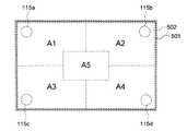
図61は、本実施形態に係るATMについて説明するための図である。同図に示すように、タッチパネル502が重ねられた液晶表示パネル501の裏面には、その四隅に計4個の振動アクチュエータ115a〜115dが設置されている。また、同図に示すように、タッチパネル502上のタッチ操作可能な領域は、複数の領域A1〜A5に区分されている。本実施形態では、振動報知を行う場合に、タッチパネル502上におけるタッチ位置が領域A1〜A5のうち、どの領域に含まれるのかに応じて、駆動する振動アクチュエータを振動アクチュエータ115a〜115dの中から切り替える。
【0245】
本実施形態に係るATMのハードウェア構成は、上記第11実施形態において図56に示したものと同様である。但し、メモリ902には、図62に示す駆動先判定テーブル902aが格納されている。同図に示すように、この駆動先判定テーブル902aには、タッチパネル502上の各区分領域A1〜A5毎に、当該区分領域をXY座標値を用いて示したエリアデータと、この区分領域がタッチ操作された場合に駆動する振動アクチュエータの識別情報とが格納されている。なお、同図においては、振動アクチュエータの識別情報として、各振動アクチュエータ115a〜115dに付した符号を用いている。
【0246】
この駆動先判定テーブル902aによれば、例えば、図61に示したタッチパネル502上において領域A1がタッチ操作された場合には、振動アクチュエータ115aのみが駆動される。また、タッチパネル502上において領域A5がタッチ操作された場合には、全ての振動アクチュエータ115a〜115dが駆動される。
【0247】
CPU904は、タッチパネル502に対するタッチ操作を検知した場合に、そのタッチ位置を検出し、駆動先判定テーブル902aを参照して駆動する振動アクチュエータを決定する。そして、CPU904は、駆動信号生成回路903を介して上記決定した振動アクチュエータを駆動してタッチパネル502および液晶表示パネル501を振動させる。
【0248】
[L−2.第12実施形態の動作]
図63は、本実施形態に係るATMにおいて、CPU904により実行される振動制御処理7の動作を説明するフローチャートである。この振動制御処理7は、タッチパネル502に対するタッチ操作が許可されている期間において、CPU904により所定周期毎に実行される。
【0249】
同図に示すように、まず、CPU904は、タッチパネル502からタッチ信号が入力されたか否かを判別する(ステップS801)。CPU904は、タッチ信号が入力されていないと判別した場合は、振動制御処理7を終了する。また、CPU904は、タッチ信号が入力されたと判別した場合は、このタッチ信号に基づいてタッチパネル502上におけるタッチ位置(XY座標値)を特定する(ステップS802)。
【0250】
次いで、CPU904は、図62に示した駆動先判定テーブル902aを参照してタッチ位置が含まれる区分領域を特定し、駆動する振動アクチュエータを決定する(ステップS803)。この後、CPU904は、決定した振動アクチュエータを駆動するための駆動信号の波形データをメモリ902から読み出す(ステップS804)。そして、CPU904は、メモリ902から読み出した波形データと、上記ステップS803において決定した振動アクチュエータの識別情報を駆動信号生成回路903に出力する。また、これと同時にCPU904は、駆動信号生成回路903に対して駆動信号の生成を指示する(ステップS805)。なお、ステップS806以降の処理は、複数の振動アクチュエータ115a〜115dのうち指定された振動アクチュエータのみを駆動する点を除いて、上記第1実施形態で説明した振動制御処理1(図5参照)のステップS104以降の処理と同様であるので説明を省略する。
【0251】
以上説明したように本実施形態によれば、CPU904は、タッチパネル502上におけるタッチ位置に応じて、駆動する振動アクチュエータを切り替える。したがって、ATMは、タッチパネル502に対するタッチ位置に応じて各振動アクチュエータ115a〜115dを効率的に駆動させることができる。
【0252】
なお、本実施形態では、タッチパネル502上の領域をあらかじめ複数の領域に区分して、各区分領域毎に、当該区分領域がタッチ操作された場合に駆動する振動アクチュエータの識別情報をメモリ902に記憶しておく構成とした。しかしながら、例えば、タッチパネル502に対するタッチ操作を検知した場合に、そのタッチ位置を検出し、当該タッチ位置と各振動アクチュエータ115a〜115dとの距離を算出して、一番近い振動アクチュエータを駆動する構成としてもよい。
【0253】
[M.第13実施形態]
本実施形態では、上記第1〜第12実施形態に用いて好適な振動発生器について説明する。なお、本実施形態における振動アクチュエータは、永久磁石を可動錘として用いており、電磁力により可動錘に直線的な往復運動を行わせて振動を発生させる、永久磁石可動型のリニア振動アクチュエータである。
【0254】
[M−1.第1例]
図64は、本実施形態の第1例に係る振動アクチュエータ950の内部構造を例示する断面図である。同図において、振動アクチュエータ950は、ケース961内部に、コイル962と、可動錘963(錘体)と、ブレーキ部材964と、スプリング966とを有する。なお、同図において、振動アクチュエータ950が振動を与える被振動体は、コイル962に対してケース961を挟んで対向する位置に設けられているものとする。また、ケース961は密閉されており、磁気シールドとして機能する。このような磁気シールドとしての機能をケース961に持たせるためには、例えば、ケース961を導電性物質で形成して接地または同電位とすること、あるいは、ケース961を透磁率の大きい磁性体で形成すればよい。
【0255】
コイル962は、同図に示すように略円筒状の形状を有するコイルであって、ケース961に固定されている。振動アクチュエータ950を駆動する場合には、このコイル962に対して交流電流(駆動信号)が印加される。
【0256】
可動錘963は、コイル962の上部に位置しており、永久磁石によって形成された略円柱状の錘である。この可動錘963の下面には、コイル962の上端部が収まる円環状の凹部が形成されている。可動錘963は、ケース961内部に形成された空間に、図中、上下方向に直線的な往復運動が可能な状態で、スプリング966により支持されている。このスプリング966は、同図に示すように、一方の端が、被振動体に接するケース961(ベース部材)につなげられており、他方の端が可動錘963につなげられている。なお、スプリング966の代わりに、例えば、ひも状のゴムなど、弾性体を用いて構成された支持部材を使用してもよい。
【0257】
この可動錘963は、コイル962に駆動信号が印加されると、このコイル962から発生する磁力により、図中、上下方向に直線的な往復運動を行う。この可動錘963の往復運動の反力として、スプリング966がつなげられたケース961部分に振動加速度が生じる。なお、スプリング966がつなげられたケース961部分には、可動錘963の往復運動に伴い、この往復運動の反力の他に、可動錘963からスプリング966を介して伝わる振動成分が加わるが、この振動アクチュエータ950における振動発生原理の基本は、可動錘963の往復運動の反力として生じた振動加速度を用いることにある。
【0258】
ブレーキ部材964は、可動錘963の側面に常時接触しているブラシ965を有する。このブラシ965は、可動錘963の側面に対して適度な接触抵抗を与えるように設計されている。ここで、ブラシ965が可動錘963に与える接触抵抗は、コイル962に駆動信号が印加され、可動錘963が往復運動を行っている場合には、その往復運動の妨げにほとんどならない。一方、コイル962への駆動信号の印加が停止された場合には、上述した接触抵抗により可動錘963の往復運動が速やかに停止する。
【0259】
すなわち、このブレーキ部材964は、コイル962への駆動信号の印加が停止されたときに、可動錘963の往復運動を速やかに停止させるためのブレーキとして作用する。なお、ブラシ965の代わりに、スポンジやウレタン、フェルト、ゴムなどで形成された部材を用いてもよい。
【0260】
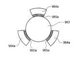
図65〜図67は、ブレーキ部材964の配置例を示す平面図であり、図64に示した断面図の図中上方から振動アクチュエータ950の内部を見た場合について示すものである。図65は、3個のブレーキ部材964aを可動錘963の周囲に120度間隔で配置した例を示すものである。また、図66は、2個のブレーキ部材964bを可動錘963を挟んで対向配置した例を示すものである。また、図67は、可動錘963の周囲を囲うように円筒状の1個のブレーキ部材964cを配置した例を示すものである。
【0261】
ここで、例えば、ブレーキ部材964aを可動錘963の周囲に1箇所だけ設けた場合、可動錘963には、このブレーキ部材964aのブラシ965aと接する1方向のみから接触抵抗が加わる。このため、往復運動時においては可動錘963の姿勢が崩れてしまい、振動アクチュエータ950から発生する振動の方向にブレが生じてしまう。また、駆動信号の印加停止時にも、可動錘963には一方向からブラシ965aによる接触抵抗が加わるため、可動錘963の姿勢が崩れ、往復運動を速やかに停止することができない。また、駆動信号の印加停止時にも振動方向に大きなブレが生じてしまう。
【0262】
以上のようなことから、図65〜図67に示したように、ブラシ965a〜965cの接触抵抗が可動錘963に対して周囲から均一に加わるようなブレーキ部材964a〜964cの配置が必要となる。また、経年変化によるブラシ965a〜965cの磨耗や、ブレーキ部材964a〜964cの変形を抑止するためには、可動錘963の往復運動に支障をきたさない範囲で、可動錘963とブラシ965a〜965cの接触面をなるべく広くとることが有効である。
【0263】
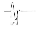
このような可動錘963のブレーキ機構の無い振動アクチュエータは、例えば、図68に示す期間T1の駆動信号の印加が停止された場合に、図69に示すように可動錘963の往復運動がすぐには止まらず、不要な振動が残ってしまう。したがって、このような振動アクチュエータは、短時間のうちに振動の強弱をはっきりと示さなければならないクリック感などの操作感覚を振動刺激によりユーザに与えることができない。また、同様に、振動時と非振動時のメリハリをはっきりとつけることができない。
【0264】
これに対して本実施形態の第1例によれば、振動アクチュエータ950は、図68に示す駆動信号の印加が停止された場合に、図70に示すように、可動錘963の往復運動がブレーキ部材964の接触抵抗により速やかに停止させられる。したがって、不要な振動が残らず、クリック感のような「かっちり」とした操作感覚を振動刺激によりユーザに与えることができる。また、振動時と非振動時のメリハリをはっきりとつけることができる。
【0265】
[M−2.第2例]
図71は、本実施形態の第2例に係る振動アクチュエータ951の内部構造を例示する断面図である。同図において、振動アクチュエータ951は、ケース961内部に、コイル962と、可動錘963と、スプリング966と、ブレーキ部材971と、ブレーキ用コイル972とを有する。なお、同図において被振動体は、コイル962に対してケース961を挟んで対向する位置に設けられている。また、ケース961、コイル962および可動錘963は、本実施形態の第1例と同じものであるため説明を省略する。
【0266】
ブレーキ部材971は、表面がゴムで覆われたブレーキ面971aとマグネット971bとを有する。また、このブレーキ部材971には、ブレーキ面971aを可動錘963の側面に引き寄せるスプリング973が取り付けられている。ブレーキ部材971は、ブレーキ用コイル972に駆動信号が印加されていない期間において、スプリング973の力によりブレーキ面971aが可動錘963の側面に押し付けられている。一方、ブレーキ用コイル972へ駆動信号が印加されている期間には、ブレーキ部材971は、マグネット971bがブレーキ用コイル972へ引き寄せられるので、ブレーキ面971aが可動錘963の側面から離れる。なお、ブレーキ面971aの表面には、ゴムの代わりに、スポンジやウレタン、フェルト、ブラシなどが取り付けられていてもよい。
【0267】
図72は、コイル962およびブレーキ用コイル972に駆動信号を印加するための回路構成を例示する図である。同図において、発振器974は、コイル962を駆動するための駆動信号を発振する。この発振器974から発振される駆動信号の波形例を図73に示す。同図に示すような交流波形がコイル962に印加されることで、可動錘963が往復運動を行う。また、ブレーキ制御回路975は、ブレーキ用コイル972へ印加する駆動信号を生成する。このブレーキ制御回路975は、発振器974から発振される駆動信号を監視し、図74に示すように、発振器974から駆動信号が発振されている期間T2の間だけ、ブレーキ用コイル972へ方形波の駆動信号を出力する。
【0268】
したがって、発振器974がコイル962へ駆動信号を印加している期間には、ブレーキ制御回路975からブレーキ用コイル972へ駆動信号が印加されるので、ブレーキ部材971のブレーキ面971aが可動錘963の側面から離れる。また、この期間においては、発振器974からコイル962へ駆動信号が供給されているので、可動錘963は往復運動を行う。これに対して、発振器974からコイル962への駆動信号の印加が停止された場合には、ブレーキ制御回路975からブレーキ用コイル972への駆動信号の印加も停止される。したがって、ブレーキ部材971のブレーキ面971aが可動錘963の側面に押し付けられ、可動錘963の往復運動を速やかに停止させる。よって、上述した本実施形態の第1例と同様の効果を奏する。
【0269】
[M−3.第3例]
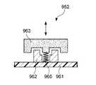
図75は、本実施形態の第3例に係る振動アクチュエータ952の内部構造を例示する断面図である。同図において、振動アクチュエータ952は、ケース961内部に、コイル962と、可動錘963と、スプリング966とを有する。これらのコイル962、可動錘963およびスプリング966は、本実施形態の第1例と同じものである。また、同図において被振動体は、コイル962とケース961を挟んで対向する位置に、ケース961に接して設けられている。
【0270】
次に、図76は、コイル962に駆動信号を印加するための回路構成を例示する図である。同図に示す発振器974は、本実施形態の第2例と同じものであるため説明を省略する。制御回路981は、スイッチ回路982内の2箇所のスイッチSW1,SW2の切り換え制御を行う。この制御回路981は、発振器974から発振される駆動信号(図73参照)を監視し、図77に示すように、発振器974から駆動信号が発振されている期間T2の間だけ“Hi”レベルとなるCTRL信号を出力する。スイッチ回路982のスイッチSW1,SW2は、制御回路981から供給されるCTRL信号が“Hi”レベルの場合に、発振器974とコイル962とを接続する。したがって、CTRL信号が“Hi”レベルの間、発振器974からコイル962へ駆動信号が印加され、可動錘963が往復運動を行う。
【0271】
これに対して、制御回路981から供給されるCTRL信号が“Low”レベルになると、すなわち、発振器974からコイル962への駆動信号の印加が停止されると、スイッチ回路982のスイッチSW1,SW2は、図76に示すように接点を切り替え、コイル962を短絡する。したがって、電磁ブレーキ作用により、駆動信号の印加停止時に可動錘963の往復運動を速やかに停止させることができる。よって、上述した本実施形態の第1例と同様の効果を奏する。
【0272】
以上説明した本実施形態の第1例〜第3例に示した振動アクチュエータ950〜952を、上記第1〜第12実施形態における電子機器の振動発生器として用いれば、ユーザに与える振動をより好適に制御することができる。
【0273】
なぜならば、まず、第1に、これらの振動アクチュエータ950〜952には、ブレーキ機構が備わっている。したがって、短時間のうちに振動の強弱をはっきりと示さなければならない、例えば、クリック感などの操作感覚をはっきりとユーザに与えることができる。
【0274】
第2に、これらの振動アクチュエータ950〜952は、リニア振動アクチュエータであるため、発生させる振動の方向精度が高い。また、第3に、これらの振動アクチュエータ950〜952は、磁気シールドとして密閉されたケース961の内部にコイル962と可動錘963とを収容しているので、周囲の電子部品などから磁力の影響を受けない。したがって、振動アクチュエータ950〜952から発生させる振動の方向にズレが生じたり、あるいは振動の振幅形状に歪みが生じることがない。以上の第2および第3の利点により、振動アクチュエータ950〜952から発生させる振動を、より木目細やかに制御することが可能となる。よって、タッチパネルに対してタッチ操作が行われた場合や、薄型の操作キーの押下操作が行われた場合に、押し込み感やクリック感を振動刺激によりユーザに与えることができる。また、振動アクチュエータ950〜952は、周囲の電子部品などに対して磁力による誤動作を生じさせることがない。
【0275】
第4に、これらの振動アクチュエータ950〜952は1パッケージ化されている。したがって、振動アクチュエータの部材を分離設置する場合と比較して、まず、永久磁石とコイルの取り付け精度の良し悪しがほとんど生じない。また、経年変化による永久磁石とコイルの設置精度の悪化が生じにくい。よって、振動アクチュエータ950〜952から安定した精度で振動を発生させることができる。また、電子機器への組み込みが容易である。さらに、振動アクチュエータ950〜952の設置された被振動部材(例えば、タッチパネルや液晶表示パネルなど)を支持する電子機器本体や筐体などの支持体が確実に固定されていない場合や、支持体の質量が被振動部材に対して十分に大きくない場合であっても、振動アクチュエータ950〜952は、十分な大きさの振動を被振動部材に与えることができる。これは、特に、軽量の電子機器や携帯型の電子機器に用いた場合に好適である。
【0276】
第5に、振動アクチュエータ950〜952において、コイル962に可聴帯域の音声信号を印加することで、振動アクチュエータ950〜952を発音源としても利用することができる。このように振動発生器と発音源とを兼用することができると、特に、小型電子機器において、構成部品の設置スペースを大幅に節約できる。
【0277】
なお、本実施形態の第1例〜第3例に示した振動アクチュエータ950〜952は、防磁効果を有するケース115aで密閉する構成としたが、このようなケース961で密閉されていなくてもよい。また、可動錘963を支持するスプリング966は、ケース961ではなく、直接、被振動体につながれていてもよい。
【0278】
[N.変形例]
以上、本発明の実施形態について説明したが、この実施形態はあくまでも例示であり、本発明の趣旨から逸脱しない範囲で様々な変形が可能である。変形例としては、例えば以下のようなものが考えられる。
【0279】
[変形例1]
上記第1実施形態において、メモリ112に複数種類の波形データを格納し、CPU113は、複数種類の波形データのうち、あらかじめユーザからの操作入力により指定された波形データを読み出して振動アクチュエータ115を駆動する構成としてもよい。このような構成とすれば、報知の際に用いる振動の形態に、より多くのバリエーションを持たせることができる。例えば、振動時間、振動の大きさ、振動の強弱の周期などを任意に変更できる。
【0280】
また、メモリ112には、駆動信号波形のサンプルデータが格納され、駆動信号生成回路114は、このサンプルデータをD/A(Digital / Analog)変換することにより駆動信号を生成する構成としてもよい。
【0281】
[変形例2]
上記第1〜第3実施形態において、さらに、振動による報知機能の有効/無効をユーザが指定可能な構成としてもよい。この場合、CPU113は、振動による報知機能を有効とするか、無効とするかをユーザに指定させるための画面表示を行う。CPU113は、ユーザからの操作入力により有効あるいは無効が指定されると、その指定内容に応じてメモリ112内の振動フラグの値を「0」(無効)あるいは「1」(有効)にセットする。そして、CPU113は、タッチパネル102や操作キー104a〜104cからの操作入力を検知した場合に、振動フラグの値に応じて振動報知を行うか否かを決定する。
【0282】
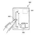
[変形例3]
例えば、図78に示すように、照明設備本体と離れた場所に設置され、設備本体に操作指令を入力するための操作パネル990に対して本発明を適用してもよい。同図に示す操作パネル990は、例えば、室内の壁面に設置されるものである。この操作パネル990の裏面には、例えば、振動アクチュエータ115などの振動発生器991が設けられている。また、図示を省略しているが、照明設備本体の制御を行う制御装置において、振動発生器991の駆動を含む振動報知の制御が行われる。
【0283】
この操作パネル990の点灯/消灯キー992をユーザが指先で切り換えると、制御装置が振動発生器991を駆動して、点灯/消灯キー992に触れているユーザの指先に振動を与える。また、この照明設備は、照明の光量を明と暗の間で連続的に可変することができる。この照明の光量を制御装置へ指示するためのスライダスイッチ993をユーザが指先で操作すると、この操作により変更された照明の光量に応じた大きさの振動が、スライダスイッチ993を操作しているユーザの指先に与えられる。なお、スライダスイッチ993の代わりに、このスライダスイッチ993と同様の機能を有する図79に示すダイアル型スイッチ994や、図80に示すプラスキー995およびマイナスキー996を用いる構成であってもよい。
【0284】
また、図81に示すように、テレビやビデオのリモートコントローラなど、タッチパネルや表示部など持たない電子機器に対しても本発明が適用可能であることは勿論である。このような電子機器の場合、操作キーからの入力を受付けたことを、操作キーや筐体を振動させてユーザに報知する構成とすればよい。
【0285】
[変形例4]
上記第1〜第12実施形態において、振動アクチュエータやバイブレータなどの振動発生器から発生させる振動の方向は、タッチパネルの表面や、操作キーの押下方向に対して垂直となる方向に限定されるものではない。また、振動アクチュエータに印加する駆動信号の周波数は、電子機器の筐体やタッチパネル、あるいはタッチパネルを具備した液晶表示パネルや振動アクチュエータ自身を共振させる周波数に限定されるものではない。同様に、バイブレータに印加する駆動電圧も、DCモータの回転数を電子機器の筐体やタッチパネル、あるいはタッチパネルを具備した液晶表示パネルやバイブレータ自身の固有振動数と一致させる駆動電圧に限定されるものではない。
【0286】
[変形例5]
上記第1〜第12実施形態において、振動発生器は、リニア振動アクチュエータや偏心錘を有するバイブレータに限定されるものではない。例えば、圧電素子を用いた振動発生器などを用いてもよい。
【0287】
また、第2実施形態を除く各実施形態では、永久磁石を可動錘として用いたリニア振動アクチュエータについて説明した。ここで、可動錘に必要となるのは、振動を発生させるために必要となる適度な質量と、当該可動錘が往復運動を行うための運動力を得る機構である。上記各実施形態では、適度な質量および運動力を得る機構として永久磁石を用いた。しかしながら、この可動錘は、錘としての部材の一部に永久磁石が組み込まれている構成であってもよい。また、リニア振動アクチュエータのケース内部に永久磁石を固定し、コイルを可動錘として用いる形態であってもよい。また、ケース内部にコイルを固定し、別のコイルを可動錘として用いる形態であってもよい。当然、このような場合に、可動錘として用いるコイルに十分な質量がない場合は、適度な質量を有する錘の一部としてコイルを用いる構成とすればよい。さらに、リニア振動アクチュエータは、鉄心可動型のリニア振動アクチュエータであってもよい。
【0288】
また、振動アクチュエータは、静電力を利用した、いわゆる静電型の振動アクチュエータであってもよい。図82は、本変形例の第1例に係る静電型の振動アクチュエータ800について説明するための図である。同図において振動アクチュエータ800は、ケース801内部に、電極802が設けられた可動錘803(錘体)と、ケース801内壁に設けられた電極804と、スプリング805とを有する。なお、同図において被振動体は、電極804に対してケース801を挟んで対向する位置に設けられているものとする。
【0289】
可動錘803は、円柱状の錘であって、その底面に円環状の電極802が設けられている。この可動錘803は、ケース801内部に形成された空間に、図中、上下方向に直線的な往復運動が可能な状態で、スプリング805により支持されている。このスプリング805は、同図に示すように、一方の端が、被振動体に接するケース801(ベース部材)につなげられており、他方の端が可動錘803につなげられている。なお、電極802を除く可動錘803は、適度な質量を有する錘であればよい。また、電極802と対向するケース801の内壁面には、円環状の電極804が設けられている。
【0290】
この電極804には、振動アクチュエータ800の外部から、プラスまたはマイナスの定電位が当該振動アクチュエータ800の駆動時に常時印加される。一方、可動錘803の電極802には、振動アクチュエータ800の外部から、プラスとマイナスに交互に振れる交流電圧(駆動信号)が増幅器810を介して印加される。
【0291】
ここで、電極802と電極803との電位が互いに同極、すなわち、プラスとプラスあるいはマイナスとマイナスになる場合は、同符合の電荷は互いに反発するという静電力の性質により、可動錘803が図中、上方向に移動する。一方、電極802と電極803との電位が互いに異極、すなわち、プラスとマイナスになる場合は、異符合の電荷は互いに吸引するという静電力の性質により、可動錘803が図中、下方向に移動する。
【0292】
このように本変形例に係る振動アクチュエータ800は、静電力により可動錘803が図中、上下方向に直線的な往復運動を行う。そして、この可動錘803の往復運動の反力として、スプリング805がつなげられたケース801部分に振動加速度が生じ、被振動体に振動が伝わる。なお、スプリング805がつなげられたケース801部分には、可動錘803の往復運動に伴い、この往復運動の反力の他に、可動錘803からスプリング805を介して伝わる振動成分が加わるが、この振動アクチュエータ800における振動発生原理の基本は、上記第1実施形態で説明した振動アクチュエータ115などと同様に、可動錘803の往復運動の反力として生じた振動加速度を用いることにある。
【0293】
また、図83は、本変形例の第2例に係る静電型の振動アクチュエータ850について説明するための図である。同図に示すような構成としても、図82に示した振動アクチュエータ800と同様に、静電力により可動錘813が往復運動を行い、振動が発生する。また、この振動アクチュエータ850は、電極812aと電極814a、電極812bと電極814bの計2対の対向電極を有し、一方の対向電極間が反発の状態にある場合は、他方の対向電極間が吸引の状態となる。したがって、図82に示した振動アクチュエータ800と比較して、可動錘813を往復運動させる静電力が倍となり、より大きな振動を発生させることができる。
【0294】
なお、図82および図83に示した静電型の振動アクチュエータ800,850に、さらに上記第13実施形態の第1例および第2例で説明したブレーキ機構を組み込んでもよい。また、電極や駆動信号の波形形状などは、図82および図83に示したものに限定されるものではない。
【0295】
[変形例6]
また、振動アクチュエータにおいて、可動錘を空中で往復運動可能に支持する支持部材は、スプリングやひも状のゴムなどに限定されるものではない。例えば、支持部材は、図84に示すようなガイドレール967であってもよい。同図において、可動錘963aには、中央部に図中、上下方向に貫通する穴が設けられている。ガイドレール967は、可動錘963aの穴を貫通するようにして設けられており、その一端が被振動体の接するケース961に固定されている。このようなガイドレール967を用いても、コイル962aから発生する磁力により可動錘963aを空中で往復運動可能に支持することができる。また、このガイドレール967は、可動錘963aの運動方向を限定し、直線的な往復運動を行わせる役割も担っている。
【0296】
[変形例7]
上記第1〜第12実施形態において、振動発生器により振動させる操作部は、タッチパネルや操作キーに限定されるものではない。例えば、複数の操作キーを有するキーボード自体や、マウス、トラックパッド、タブレットなどの各種ポインティングディバイスであってもよい。また、光結合型、抵抗型、接触型、磁気結合型、容量結合型などの様々なタイプのタッチパネルを用いることができる。
【0297】
[変形例8]
上記第1実施形態〜第12実施形態では、本発明をPDAやATMに適用した場合について説明した。しかしながら、本発明は、例えば、携帯電話機、電子手帳、モバイル型コンピュータ、腕時計、電卓、電子機器のリモートコントローラなどの各種携帯型電子機器に適用可能であることは勿論である。さらに、本発明は、据置型のコンピュータや、自動販売機、キャッシュレジスタ、カーナビゲーション装置、家電製品など、携帯性を有さない各種電子機器に対しても適用可能である。
【0298】
なお、携帯性を有さない電子機器においては、当該電子機器をユーザが一方の手で把持しながら他方の手で操作入力を行うという使用形態は想定しにくい。したがって、このような電子機器において操作部以外の部位を振動させる場合には、操作時にユーザの体の一部が接触する、または接触するであろうと想定される筐体の一部分を振動させる構成とすればよい。
【0299】
例えば、図85は、本変形例に係るATM150の外観を例示する斜視図である。同図において、ATM150の操作卓151上には、透明のタッチパネル152が重ねられた液晶表示パネル153が開口部に臨んで設けられている。ユーザは、操作卓151の前に立って、タッチパネル152に対するタッチ操作を行う。なお、操作卓151上には、タッチパネル152の他に紙幣入出金口154や硬貨入出金口155が設けられている。また、ATM150の正面上方の側面には、通帳挿入口156やカード挿入口157が設けられている。
【0300】
このようなATM150に対してユーザがタッチ操作を行う場合、タッチ操作を行う手とは異なるもう一方の手が、操作卓151の卓上領域151aまたは卓上領域151bにおかれていることなどが想定できる。したがって、ATM150の制御部は、タッチパネル152に対するタッチ操作の検知に応じて図示を省略した振動発生器を駆動し、卓上領域151aまたは卓上領域151bを振動させる構成とすればよい。また、同様にユーザがタッチ操作を行っている場合、この操作卓151の手前に設けられた卓縁部材158に、ユーザの大腿部や胴体の一部分が接触していることが想定できる。したがって、ATM150の制御部は、タッチパネル152に対するタッチ操作の検知に応じて、この卓縁部材158を振動させる構成とすればよい。
【0301】
【発明の効果】
以上説明したように本発明によれば、電子機器は、操作入力が受付けられたことや操作入力に対する応答を振動によりユーザへ報知することができる。ユーザは、画面表示を見なくても、操作入力の受付有無や操作入力に対する電子機器の応答結果を振動により確認することができる。
【図面の簡単な説明】
【図1】 本発明の第1実施形態に係るPDAの外観を例示する斜視図である。
【図2】 同実施形態に係るPDAのハードウェア構成を例示するブロック図である。
【図3】 同実施形態に係るPDAの本体ケース内において、振動アクチュエータの設置状態を模式的に例示する断面図である。
【図4】 同実施形態に係る振動アクチュエータに印加される駆動信号の波形を例示する図である。
【図5】 同実施形態に係るPDAにおいて、CPUにより実行される振動制御処理1の動作を説明するフローチャートである。
【図6】 本発明の第2実施形態に係るPDAのハードウェア構成を例示するブロック図である。
【図7】 同実施形態に係るPDAの本体ケース内において、バイブレータの設置状態を模式的に例示する断面図である。
【図8】 同実施形態に係るDCモータの外観を例示する斜視図である。
【図9】 同実施形態に係るバイブレータに印加される駆動電圧の波形について例示する図である。
【図10】 同実施形態に係るタッチパネルの表面に生じる振動について例示する図である。
【図11】 同実施形態に係るPDAにおいて、CPUにより実行される振動制御処理2の動作を説明するフローチャートである。
【図12】 本発明の第3実施形態に係るPDAの外観を例示する斜視図である。
【図13】 同実施形態に係るPDAのハードウェア構成を例示するブロック図である。
【図14】 同実施形態に係るPDAにおいて、CPUにより実行される振動制御処理3の動作を説明するフローチャートである。
【図15】 同実施形態に係るPDAにおいて、CPUにより実行される振動制御処理4の動作を説明するフローチャートである。
【図16】 本発明の第4実施形態に係るPDAの内部構造を例示する図である。
【図17】 同実施形態に係るPDAのハードウェア構成を例示するブロック図である。
【図18】 同実施形態に係るPDAにおいて、CPUにより実行される振動制御処理5の動作を説明するフローチャートである。
【図19】 同実施形態の第1の変形例に係るPDAの内部構造を例示する断面図である。
【図20】 同変形例に係る弾性部材の他の設置例を示す図である。
【図21】 同変形例に係る弾性部材のその他の設置例を示す図である。
【図22】 同変形例に係る弾性部材のその他の設置例を示す図である。
【図23】 同実施形態の第2の変形例に係るPDAの内部構造を例示する図である。
【図24】 同実施形態の第3の変形例に係るPDAの内部構造を例示する図である。
【図25】 本発明の第5実施形態に係るATMの内部構造を説明するための断面図である。
【図26】 同実施形態に係る振動アクチュエータの設置位置の変形例を示す断面図である。
【図27】 同実施形態の第1の変形例に係るATMの内部構造を例示する断面図である。
【図28】 同実施形態の第2の変形例に係るATMの内部構造を例示する図である。
【図29】 同実施形態の第3の変形例に係るATMの内部構造を例示する図である。
【図30】 同実施形態の第4の変形例に係るATMの内部構造を例示する図である。
【図31】 同実施形態の第5の変形例に係るATMの内部構造を例示する図である。
【図32】 本発明の第6実施形態の第1例に係るPDAの画面表示例を示す図である。
【図33】 同実施形態の第1例に係るPDAにおいて、メモリに格納されている波形データテーブルを例示する図である。
【図34】 同実施形態の第1例に係るPDAにおいて、振動アクチュエータに印加される駆動信号の波形を例示する図である。
【図35】 同実施形態の第1例に係るPDAにおいて、振動アクチュエータに印加される駆動信号の波形を例示する図である。
【図36】 同実施形態の第1例に係るPDAにおいて、振動アクチュエータに印加される駆動信号の波形を例示する図である。
【図37】 同実施形態の第1例に係るPDAにおいて、振動アクチュエータに印加される駆動信号の波形を例示する図である。
【図38】 同実施形態の第2例に係るPDAの画面表示例を示す図である。
【図39】 同実施形態の第2例に係るPDAの画面表示例を示す図である。
【図40】 同実施形態の第2例に係るPDAにおいて、メモリに格納されている波形データテーブルを例示する図である。
【図41】 同実施形態の第3例に係るPDAの画面表示例を示す図である。
【図42】 同実施形態の第3例に係るPDAにおいて、メモリに格納されている波形データテーブルを例示する図である。
【図43】 同実施形態の第3例に係るPDAにおいて、振動アクチュエータに印加される駆動信号の波形を例示する図である。
【図44】 同実施形態の第3例に係るPDAにおいて、振動アクチュエータに印加される駆動信号の波形を例示する図である。
【図45】 同実施形態の第3例に係るPDAにおいて、振動アクチュエータに印加される駆動信号の波形を例示する図である。
【図46】 本発明の第7実施形態に係るPDAにおいて、メモリに格納されている波形データテーブルを例示する図である。
【図47】 本発明の第8実施形態に係るPDAのハードウェア構成を例示するブロック図である。
【図48】 同実施形態に係るPDAにおいて、CPUにより実行される報知制御処理1の動作を説明するフローチャートである。
【図49】 同実施形態に係るPDAにおいて、振動アクチュエータに印加される振動用の駆動信号の波形を例示する図である。
【図50】 同実施形態に係るPDAにおいて、振動アクチュエータに印加されるビープ音用の駆動信号の波形を例示する図である。
【図51】 同実施形態に係るPDAにおいて、振動とビープ音とによる報知を同時に行う場合に振動アクチュエータに印加される駆動信号の波形を例示する図である。
【図52】 本発明の第9実施形態に係るPDAのハードウェア構成を例示するブロック図である。
【図53】 同実施形態に係るPDAにおいて、CPUにより実行されるビーコン受信処理の動作を説明するフローチャートである。
【図54】 本発明の第10実施形態に係るPDAにおいて、メモリに格納されている報知モード判定テーブルを例示する図である。
【図55】 本発明の第11実施形態に係るATMについて説明するための図である。
【図56】 同実施形態に係るATMのハードウェア構成を例示するブロック図である。
【図57】 同実施形態に係るATMにおいて、CPUにより実行される振動制御処理6の動作を説明するフローチャートの一部である。
【図58】 同実施形態に係るATMにおいて、CPUにより実行される振動制御処理6の動作を説明するフローチャートの一部である。
【図59】 同実施形態の変形例に係るATMのタッチパネルについて説明するための断面図である。
【図60】 同実施形態の変形例に係るATMのタッチパネルについて説明するための断面図である。
【図61】 本発明の第12実施形態に係るATMについて説明するための図である。
【図62】 同実施形態に係るATMにおいて、メモリに格納されている駆動先判定テーブルを例示する図である。
【図63】 同実施形態に係るATMにおいて、CPUにより実行される振動制御処理7の動作を説明するフローチャートである。
【図64】 本発明の第13実施形態の第1例に係る振動アクチュエータの内部構造を例示する断面図である。
【図65】 同実施形態の第1例に係る振動アクチュエータにおいて、ブレーキ部材の配置例を示す平面図である。
【図66】 同実施形態の第1例に係る振動アクチュエータにおいて、ブレーキ部材の他の配置例を示す平面図である。
【図67】 同実施形態の第1例に係る振動アクチュエータにおいて、ブレーキ部材のその他の配置例を示す平面図である。
【図68】 同実施形態の第1例に係る振動アクチュエータのコイルに印加される駆動信号の波形を例示する図である。
【図69】 ブレーキ機構のない振動アクチュエータの可動錘の往復運動を説明するための図である。
【図70】 同実施形態の第1例に係る振動アクチュエータの可動錘の往復運動を説明するための図である。
【図71】 同実施形態の第2例に係る振動アクチュエータの内部構造を例示する断面図である。
【図72】 同実施形態の第2例に係る振動アクチュエータのコイルおよびブレーキ用コイルに駆動信号を印加するための回路構成を例示する図である。
【図73】 同実施形態の第2例に係る振動アクチュエータのコイルに印加される駆動信号の波形を例示する図である。
【図74】 同実施形態の第2例に係る振動アクチュエータのブレーキ用コイルに印加される駆動信号の波形を例示する図である。
【図75】 同実施形態の第3例に係る振動アクチュエータの内部構造を例示する断面図である。
【図76】 同実施形態の第3例に係る振動アクチュエータのコイルに駆動信号を印加するための回路構成を例示する図である。
【図77】 同実施形態の第3例に係るスイッチ回路に供給されるCTRL信号の波形を例示する図である。
【図78】 本発明の変形例3に係る操作パネルについて例示する図である。
【図79】 同変形例に係るダイアル式スイッチを例示する図である。
【図80】 同変形例に係る「+」キーおよび「−」キーを例示する図である。
【図81】 同変形例に係る電子機器のリモートコントローラの外観を例示する斜視図である。
【図82】 本発明の変形例5に係る静電型の振動アクチュエータについて説明するための図である。
【図83】 本発明の変形例5に係る他の静電型の振動アクチュエータについて説明するための図である。
【図84】 本発明の変形例6に係る振動アクチュエータの内部構造を例示する断面図である。
【図85】 本発明の変形例8に係るATMの外観を例示する斜視図である。
【符号の説明】
10,20,30,40〜43,60,70……PDA、50〜55,90,150……ATM、50a……本体装置、101,301,401,401a……本体ケース、102,152,502……タッチパネル、103,302,901……表示部、103a,302a,153,501……液晶表示パネル、104a,104b,104c……操作キー、111,303……キー入力部、112,902……メモリ、112a〜112d……波形データテーブル、112e……報知モード判定テーブル、113,904……CPU、114,211,903……駆動信号生成回路、115,115a〜115c,800,850,950〜953……振動アクチュエータ、115a,801,811,961……ケース、121、962,962a……コイル、122,803,813,963,963a……可動錘、123、805,815a,815b、966……スプリング、212……バイブレータ、213……エンコーダ、221……回転軸、222……偏心錘、223……DCモータ、150a……本体カバー、151……操作卓、151a,151b……卓上領域、158……卓縁部材、304,701……無線通信部、411……タッチセンサ、451,451a〜451f……弾性部材、503……ダンパ、504……本体カバー、550……変形層、601……マイクロフォン、602……音量測定回路、603……ビープ音生成回路、604……スピーカ、802,804,812a,812b,814a,814b……電極、810…増幅器、964,964a〜964c,971……ブレーキ部材、965.965a〜965c……ブラシ、967……ガイドレール、971a……ブレーキ面、971b……マグネット、972……ブレーキ用コイル、973……スプリング、974……発振器、975……ブレーキ制御回路、981……制御回路、982……スイッチ回路、990……操作パネル、991……振動発生器。[0001]
BACKGROUND OF THE INVENTION
The present invention relates to a portable electronic device, an electronic device, a vibration generator, a notification method by vibration, and a notification control method, and more particularly to a user interface and a vibration generation mechanism of the electronic device.
[0002]
[Prior art]
Various electronic devices such as a PDA (Personal Digital Assistant), a personal computer, and an ATM (Automatic Tellers Machine) have user interfaces such as operation buttons, a keyboard, and a touch panel. The user performs operation input to the electronic device such as input of characters and selection of processing to be executed through these user interfaces.
[0003]
[Problems to be solved by the invention]
However, for example, in portable electronic devices equipped with a keyboard and operation buttons, keys and operation buttons have been reduced in size, weight, and thickness with the reduction in size, weight, and thickness of portable electronic devices. Poor feeling when pressing keys or operation buttons. For this reason, the user has to confirm whether or not the portable electronic device has accepted the pressing operation of the key or the operation button by looking at the display content of the screen.
[0004]
For example, in an electronic device including a touch panel, a touch operation with a fingertip or an attached pen is performed on the touch panel. At this time, if the touch of the fingertip or the pen with the touch panel is bad or the degree of pressing is weak, the touch operation becomes invalid. For this reason, the user still has to check whether the touch operation on the touch panel is accepted by the electronic device by looking at the display content on the screen.
[0005]
In addition, there is an electronic device that notifies a user that an operation input has been received using a beep sound or the like, but such notification using sound has little effect under noise in, for example, a city.
[0006]
The present invention has been made in view of the above-described circumstances, and allows the user to easily confirm that the operation input has been accepted and the response of the electronic device to the operation input without looking at the screen. An object is to provide an electronic device, an electronic device, a vibration generator, a notification method using vibration, and a notification control method.
[0007]
[Means for Solving the Problems]
To solve the above problem,The invention according to claim 94 of the present application provides a weight, and the vibration generator that supports the weight so as to reciprocate in the air, and that the vibration generator gives vibration or is in contact with the vibration object. A support member connected to the base member, a movement force generating means for applying a movement force to cause the weight body to reciprocate, and when the generation of the movement force from the movement force generation means stops, the weight There is provided a vibration generator comprising brake means for contacting a body and stopping the reciprocating motion of the weight body.
[0008]
According to this invention, when the generation of the kinetic force from the kinetic force generating means stops, the brake means immediately stops the reciprocating motion of the weight body.
[0009]
The invention according to claim 95 of the present application is characterized in that an operation unit that accepts an operation input, a vibration generator according to claim 94 that applies vibration to a gripping unit of the portable electronic device, and an operation input to the operation unit. Provided is a portable electronic device comprising vibration control means for generating a vibration from the vibration generator when it is detected that it has been received. The invention according to
Also,
[0010]
According to the present invention, the portable electronic device notifies the operator that the operation input has been accepted by vibrating the operation unit.
[0011]
Also,Claim 97 of the present applicationThe invention provides an operation unit that accepts an operation input and provides vibration to the operator.95.A portable device comprising: a vibration generator; and vibration control means for generating vibration from the vibration generator when it is detected that execution of processing instructed by an operation input to the operation unit has been completed. Type electronics. Also,Claim 117 of the present applicationThe present invention is a method of notifying by vibration in a portable electronic device, and is provided in the portable electronic device when it is detected that the execution of a process instructed by an operation input to the operation unit is completed.95.Provided is a vibration notification method characterized by generating vibration from a vibration generator to give vibration to an operator.
[0012]
According to this invention, the portable electronic device notifies the operator by vibration that the execution of the process instructed by the operation input has been completed.
[0013]
Also,Claim 98 of this applicationThe present invention relates to an operation unit that receives an operation input, a first vibration generator that applies vibration to the operation unit, a second vibration generator that applies vibration to a grip unit of the portable electronic device, and the operation unit. Vibration control means for generating vibration from at least one of the first vibration generator and the second vibration generator designated in advance by the operator when it is detected that an operation input has been received. AndAnd at least one of the first and second vibration generators is the vibration generator according to claim 94.Provide portable electronic devices. Also,Claim 128.The present invention provides a method for notifying by vibration in a portable electronic device, and when detecting that an operation input to the operation unit is accepted, the portable electronic device is provided with a vibration to the operation unit. Of the first vibration generator and the second vibration generator that applies vibration to the grip portion of the portable electronic device, vibration is generated from any one or more designated in advance by the operator, and vibration is given to the operator.95. A notification method, wherein at least one of the first and second vibration generators is the vibration generator according to claim 94.A notification method by vibration is provided.
[0014]
According to the present invention, the portable electronic device notifies the operator that the operation input has been accepted by vibrating the part designated in advance by the operator.
[0015]
Also,Claim 99 of this applicationThe invention includes an operation unit that receives an operation input, a first vibration generator that applies vibration to the operation unit, a second vibration generator that applies vibration to a gripping part of the portable electronic device, and the portable electronic device. The first vibration generator and the second vibration generator when detecting that a device is gripped by an operator and detecting that an operation input to the operation unit is received. Vibration control means for selecting any one or more according to the detection result by the detection means and generating vibration from the selected vibration generator.And at least one of the first and second vibration generators is the vibration generator according to claim 94.Provide portable electronic devices. Also,Claim 119 of this applicationThe present invention provides a method for notifying by vibration in a portable electronic device, and when detecting that an operation input to the operation unit is accepted, the portable electronic device is provided with a vibration to the operation unit. Of the first vibration generator and the second vibration generator that applies vibration to the grip portion of the portable electronic device, the detection result of the sensor that detects whether the portable electronic device is gripped by the operator Depending on the selection, select one or more and generate vibration from the selected vibration generator to give vibration to the operator.95. A notification method, wherein at least one of the first and second vibration generators is the vibration generator according to claim 94.A notification method by vibration is provided.
[0016]
According to this invention, the portable electronic device notifies the operator that the operation input has been accepted by vibrating different parts depending on whether or not the portable electronic device is held by the operator. .
[0017]
Also,According to
[0018]
According to the present invention, the electronic device vibrates the touch panel together with the display panel to notify the operator that the touch operation has been accepted.
[0019]
Also,
[0020]
According to the present invention, the electronic device vibrates the touch panel together with the display panel to notify the operator that the touch operation has been accepted.
[0021]
Also,Claim 102.The invention is provided between a display, a touch panel that covers a display screen of the display, and the display and the touch panel, and supports the touch panel on the display screen and gives vibration to the touch panel.95.Provided is an electronic device comprising a vibration generator and vibration control means for generating vibration from the vibration generator when it is detected that a touch operation on the touch panel is accepted.
[0022]
According to the present invention, the electronic device notifies the operator that the touch operation has been accepted by vibrating the touch panel.
[0023]
Also,
[0024]
According to this invention, the electronic device vibrates only the touch panel on the display screen and notifies the operator that the touch operation has been accepted.
[0025]
Also,Claim 104.The invention provides an operation unit that receives an operation input and at least a part of the operation unit that is exposed to the outside from the casing of the electronic device, and directly vibrates the operator.95.Provided is an electronic device comprising a vibration generator and vibration control means for generating vibration from the vibration generator when it is detected that an operation input to the operation unit has been received.
[0026]
According to the present invention, the electronic device notifies the operator that the touch operation has been accepted by directly vibrating the vibration generator.
[0027]
Also,Claim 105 of the present applicationThe invention provides an operation unit that receives an operation input, and applies vibration to a part of the casing of the electronic device that is different from the operation unit.95.When it is detected that an operation input to the vibration generator and the operation unit has been received, the type of the operation input is specified, and vibration is generated from the vibration generator in a vibration form associated with the type of the operation input. There is provided an electronic device comprising a vibration control means for generating a vibration. Also,Claim 120 of this applicationThe present invention is a method for notifying by vibration in an electronic device, and when it is detected that an operation input to the operation unit is received, the type of the operation input is specified and the electronic device is provided.95.There is provided a notification method by vibration that generates vibration in a vibration form associated with the type of operation input from a vibration generator and vibrates a part of the casing of the electronic device different from the operation unit.
[0028]
According to this invention, the electronic device notifies the operator that a part of the housing different from the operation unit is vibrated in a vibration mode corresponding to the type of the operation input, in response to the acceptance of the operation input.
[0029]
Also,Claim 106.The invention provides an operation unit that receives an operation input, and applies vibration to a part of the casing of the electronic device that is different from the operation unit.95.A vibration generator, a changing means for changing a parameter value for controlling the electronic device in accordance with an operation input to the operation unit, and an operation input for changing the parameter value to the operation unit are accepted. And a vibration control means for generating a vibration from the vibration generator in a vibration form associated with the parameter value changed by the changing means by the operation input.
[0030]
According to the present invention, the electronic device is operated by vibrating a part of the housing different from the operation unit in a vibration mode corresponding to the changed parameter value that the operation input for changing the parameter value is accepted. Inform the person.
[0031]
Also,Claim 107 of the present applicationThe invention provides an operation unit that receives an operation input, and provides vibration to the operation unit.95.When it is detected that an operation input to the vibration generator and the operation unit has been received, the type of the operation input is specified, and vibration is generated from the vibration generator in a vibration form associated with the type of the operation input. The vibration generator supports the weight body and the weight body so that the weight body can reciprocate in the air, and the operation portion or a base of the vibration generator in contact with the operation portion. There is provided an electronic apparatus comprising a support member connected to a member and a kinetic force generating means for applying a kinetic force for causing the weight to reciprocate. Also,
[0032]
According to the present invention, the electronic device vibrates the operation unit in a vibration mode corresponding to the type of the operation input and notifies the operator that the operation input has been accepted.
[0033]
Also,Claim 108.The invention provides an operation unit that receives an operation input, and provides vibration to the operation unit.95.A vibration generator, a changing means for changing a parameter value for controlling the electronic device in accordance with an operation input to the operation unit, and an operation input for changing the parameter value to the operation unit are accepted. Vibration control means for generating vibration from the vibration generator in a vibration form associated with the parameter value changed by the change means by the operation input, the vibration generator, A weight, a support member connected to the operation member or a base member of the vibration generator that is in contact with the operation member, and a weight member that supports the weight member so as to reciprocate in the air. There is provided an electronic device including a kinetic force generating means for providing a kinetic force for the purpose.
[0034]
According to the present invention, the electronic device notifies the operator that the operation input for changing the parameter value is accepted by vibrating the operation unit in a vibration mode corresponding to the changed parameter value.
[0035]
Also,Claim 109 of this applicationThe present invention provides an operator that continuously changes a parameter value for controlling the electronic device and a vibration to the operator.95.A vibration generator, a changing means for changing the parameter value based on an operation amount of the operation element, and when the operation of the operation element is detected to be received, the operation is changed by the changing means. There is provided an electronic apparatus comprising vibration control means for generating vibration from the vibration generator in a vibration form associated with a parameter value.
[0036]
According to the present invention, the electronic device notifies the operator that the operation of the operator that continuously changes the parameter value is accepted in a vibration mode corresponding to the changed parameter value.
[0037]
Also,Claim 110 of this applicationThe invention receives an operation input and detects an operation level of the operation input and vibrates the operator.95.When it is detected that an operation input to the vibration generator and the operation unit has been received, vibration is generated from the vibration generator in a vibration form associated with the pressing level of the operation input detected by the operation unit. Provided is an electronic device comprising vibration control means for generating vibration.
[0038]
According to the present invention, the electronic device notifies the operator that the operation input has been accepted in a vibration mode corresponding to the pressing level of the operation input.
[0039]
Also,
[0040]
According to the present invention, the electronic device notifies the operator that the operation input has been received by vibration or sound designated in advance by the operator.
[0041]
Also,
[0042]
According to this invention, the electronic device notifies the operator that the operation input has been accepted by vibration or sound according to the volume around the electronic device.
[0043]
Also,
[0044]
According to the present invention, the electronic device notifies the operator that the operation input has been accepted by vibration or sound according to an instruction from the base station covering the area where the electronic device is located.
[0045]
Also,
[0046]
According to this invention, the electronic device notifies the operator that the operation input has been received by vibration or sound according to the current position of the electronic device.
[0047]
Also,
[0048]
According to this invention, the electronic device switches the vibration generator to be driven according to the touch position when notifying the operator that the touch operation has been accepted by vibration.
[0049]
Also,Claim 3 of the present applicationThe invention includes an operation panel that receives a touch operation, a plurality of vibration generators that apply vibration to the operation panel, a detection unit that detects a touch position on the operation panel, and a touch operation on the operation panel. When detected, the plurality of vibrations are amplified so that the amplitude of vibration generated at the touch position of the touch operation detected by the detection means is amplified by mutual interference of vibration waves generated from each of the plurality of vibration generators. Generating means for generating a drive signal for driving each of the vibration generators, and vibration for generating a vibration from each of the vibration generators by applying each of the drive signals generated by the generating means to the corresponding vibration generator Provided is an electronic device comprising a control means. Also,Claim 92.The present invention is a method of notifying by vibration in an electronic device, and when detecting that a touch operation on the operation panel is accepted, the touch position is detected, and each of a plurality of vibration generators included in the electronic device is provided. Generating a drive signal to be applied to each of the plurality of vibration generators so that the amplitude of vibration generated at the touch position of the operation panel is amplified by mutual interference of vibration waves generated from Provided is a vibration notification method for driving and applying vibration to an operator.
[0050]
According to the present invention, when the electronic device generates vibrations from a plurality of vibration generators and notifies the operator that the touch operation has been accepted, the electronic device is caused by mutual interference of vibration waves generated from the vibration generators. The amplitude of vibration generated at the touch position on the operation panel is amplified.
[0051]
Also,Claim 6 of this applicationThe invention includes an operation panel in which a deformation layer that can be deformed by vibration is laminated, a plurality of vibration generators that apply vibration to the operation panel, a detection unit that detects a touch position on the operation panel, and a touch on the operation panel. The thickness of the deformation layer at the touch position of the touch operation detected by the detection means due to mutual interference of vibration waves generated from each of the plurality of vibration generators when it is detected that the operation is accepted Generating means for generating a drive signal for driving each of the plurality of vibration generators, and the vibration corresponding to each of the drive signals generated by the generating means so that the thickness is thinner or thicker than when not touched. Provided is an electronic device comprising vibration control means for applying vibration to each generator and generating vibration from each vibration generator.
[0052]
According to the present invention, when the electronic device generates vibrations from a plurality of vibration generators and notifies the operator that the touch operation has been accepted, the electronic device is caused by mutual interference of vibration waves generated from the vibration generators. The layer thickness of the deformation layer at the touch position on the operation panel is made thinner or thicker than that at the time of non-touch.
[0057]
DETAILED DESCRIPTION OF THE INVENTION
Embodiments of the present invention will be described below. Such an embodiment shows one aspect of the present invention, and does not limit the present invention, and can be arbitrarily changed within the scope of the present invention.
[0058]
[A. First Embodiment]
[A-1. Configuration of First Embodiment]
FIG. 1 is a perspective view illustrating the appearance of the
[0059]
Next, FIG. 2 is a block diagram illustrating a hardware configuration of the
[0060]
The
[0061]
The
[0062]
The drive
[0063]
The
[0064]
FIG. 3 is a cross-sectional view schematically illustrating an installation state of the
[0065]
The
[0066]
The
[0067]
When an alternating current (drive signal) is applied to the
[0068]
The vibration is transmitted to the liquid
[0069]
The
[0070]
By the way, using the
[0071]
In such a case, if the mounting accuracy of a separately installed member is poor, or if the mounting accuracy of the member deteriorates due to secular change, this immediately appears as a vibration problem of the touch panel, and vibrates the touch panel with stable accuracy. Is difficult. In addition, the process of assembling the electronic equipment such as the large number of parts and the positioning of the permanent magnet and the coil becomes complicated, and the product cost increases accordingly.
[0072]
Furthermore, when performing such remote installation, in order to vibrate the touch panel efficiently, a support body such as a main body device or a housing of an electronic device that supports the liquid crystal display panel is securely fixed, or the support body. Must be sufficiently large relative to the liquid crystal display panel. Therefore, the separate installation of the vibration actuator is not suitable for lightweight electronic devices and portable electronic devices.
[0073]
On the other hand, when the
[0074]
Furthermore, the
[0075]
When an audio signal in the audible band is applied to the
[0076]
Next, FIG. 4 is a diagram illustrating the waveform of the drive signal applied to the
[0077]
The frequency f of the drive signal0Is the frequency f0Is the natural frequency f1Or the natural frequency f2It may be determined to match. Such frequency f0Even so, the
[0078]
[A-2. Operation of First Embodiment]
FIG. 5 is a flowchart for explaining the operation of the
[0079]
As shown in the figure, first, the
[0080]
Note that even if the
[0081]
Next, the
[0082]
Next, the
[0083]
Further, the
[0084]
When the application time is equal to or shorter than the specified time, the
[0085]
As described above, according to the present embodiment, the
[0086]
In addition, since a linear vibration actuator is used as the
[0087]
Further, by applying an audio signal in the audible band to the
[0088]
Further, by reducing the vibration time to a short time such as 0.5 seconds, for example, when the
[0089]
The
[0090]
Preventing the
[0091]
Further, it is important for the
[0092]
In the present embodiment, the configuration in which the operation units such as the
[0093]
[B. Second Embodiment]
In the present embodiment, a case where a vibrator using a DC motor is used as a vibration generator will be described. In the present embodiment, the same reference numerals are used for portions common to the first embodiment. Also, the description of the parts common to the first embodiment will be omitted.
[0094]
[B-1. Configuration of Second Embodiment]
FIG. 6 is a block diagram illustrating a hardware configuration of the
[0095]
The
[0096]
The drive
[0097]
FIG. 7 is a cross-sectional view schematically illustrating the installation state of the
[0098]
When a driving voltage (driving signal) is applied to the
[0099]
For this reason, as shown in FIG. 6, the
[0100]
As described above, by controlling the stop position of the
[0101]
Next, FIG. 9 is a diagram illustrating the waveform of the drive voltage applied to the
[0102]
Therefore, in the present embodiment, the rotational frequency of the
[0103]
[B-2. Operation of Second Embodiment]
FIG. 11 is a flowchart for explaining the operation of the
[0104]
However, in this embodiment, since the
[0105]
If the
[0106]
Next, the
[0107]
As described above, according to the present embodiment, the
[0108]
In the present embodiment, the
[0109]
[C. Third Embodiment]
In the present embodiment, a description will be given of a portable electronic device that notifies the end of execution of a process by vibration when the execution of the process instructed by an operation input is completed. In the present embodiment, the same reference numerals are used for portions common to the first embodiment. Also, the description of the parts common to the first embodiment will be omitted.
[0110]
[C-1. Configuration of Third Embodiment]
FIG. 12 is a perspective view illustrating the appearance of the
[0111]
FIG. 13 is a block diagram illustrating a hardware configuration of the
[0112]
The
[0113]
The
[0114]
[C-2. Operation of Third Embodiment]
FIG. 14 is a flowchart for explaining the operation of the vibration control process 3 executed by the
[0115]
As shown in the figure, first, the
[0116]
With such a control configuration, when the
[0117]
By the way, for example, when the end of execution of the mail check process is notified by vibration, it is effective to change the form of vibration depending on whether or not there is a self-addressed e-mail. A control method for changing the form of vibration in accordance with the result of the executed process will be described below.
[0118]
FIG. 15 is a flowchart for explaining the operation of the
[0119]
Next, the
[0120]
The processing after step S405 is the same as the processing after step S303 of the above-described vibration control processing 3 (see FIG. 14), and thus detailed description thereof will be omitted. However, the
[0121]
As described above, according to the present embodiment, the
[0122]
In the present embodiment, the case where the vibration time is changed according to the execution result of the process has been described. However, the magnitude of vibration, the number of times of vibration, and the like may be changed. In short, the form of vibration generated from the
[0123]
Moreover, in this embodiment, the structure which vibrates the
[0124]
[D. Fourth Embodiment]
In the present embodiment, a portable electronic device that switches a vibration site to a touch panel or a grip portion of a housing according to whether or not the portable electronic device is held by a user will be described. In the present embodiment, the same reference numerals are used for portions common to the first embodiment. Also, the description of the parts common to the first embodiment will be omitted.
[0125]
[D-1. Configuration of Fourth Embodiment]
FIG. 16 is a diagram illustrating the internal structure of the
[0126]
On the other hand, a
[0127]
Thus, the
[0128]
In this embodiment, as an example of control, when the
[0129]
FIG. 17 is a block diagram illustrating a hardware configuration of the
[0130]
The
The
[0131]
The
[0132]
The drive
[0133]
[D-2. Operation of Fourth Embodiment]
FIG. 18 is a flowchart for explaining the operation of the vibration control process 5 executed by the
[0134]
As shown in the figure, first, the
[0135]
On the other hand, if the
[0136]
On the other hand, if the
[0137]
Since the processing after step S505 is the same as the processing after step S102 of the vibration control processing 1 (see FIG. 5) described in the first embodiment, the detailed description thereof will be omitted. The vibration actuator determined by the processing of S503 or S504 is driven to apply vibration to the
[0138]
As described above, according to the present embodiment, the
[0139]
In the present embodiment, the vibration actuator used at the time of vibration notification may be configured to be designated by the user. In this case, the
[0140]
FIG. 19 is a cross-sectional view illustrating the internal structure of a
[0141]
Note that the
[0142]
As shown in FIG. 23, the
[0143]
Furthermore, as shown in FIG. 24, the
[0144]
[E. Fifth Embodiment]
In this embodiment, the installation location of the vibration generator that vibrates the touch panel will be described.
FIG. 25 is a cross-sectional view for explaining the internal structure of the
[0145]
Here, the
[0146]
The
[0147]
As shown in the figure, the liquid
[0148]
Note that the control for generating vibration from the
[0149]
As described above, according to the present embodiment, the
[0150]
As shown in FIG. 26, the
[0151]
Here, the liquid
[0152]
FIGS. 28 to 31 are cross-sectional views illustrating the internal structure of
[0153]
Further, as shown in FIG. 29, a liquid
[0154]
Alternatively, as shown in FIG. 30, a liquid
[0155]
In addition, as shown in FIG. 31, a liquid
[0156]
Each of the modified examples shown in FIGS. 28 to 31 vibrate the
[0157]
In the present embodiment, the case where a liquid crystal display is used as the display has been described. However, the display may be a CRT, a plasma display, an EL (Electronic Luminescence) display, or the like. Further, the number of
[0158]
[F. Sixth Embodiment]
In the present embodiment, an electronic device that notifies a user that an operation input has been accepted with vibrations of different forms depending on the type of the operation input will be described. In the present embodiment, description will be made based on the
[0159]
[F-1. First example]
FIG. 32 is a diagram illustrating a screen display example of the
[0160]
Next, FIG. 33 is a diagram illustrating a waveform data table 112 a stored in the
[0161]
Here, the waveforms of the drive signals associated with the touch buttons have different amplitudes and shapes as illustrated in FIGS. 34 to 37, for example. However, in each of these drawings, the frequency f of the drive signal0Is a frequency at which any of the
[0162]
When the user touches the
[0163]
Then, the
[0164]
As described above, according to the first example of the present embodiment, when detecting a touch operation on the
[0165]
Note that when the user presses a location on the
[0166]
The invention according to the first example of the present embodiment can also be applied to an electronic device having a plurality of operation keys instead of the
[0167]
[F-2. Second example]
FIG. 38 and FIG. 39 are diagrams illustrating a state in which an icon displayed on the display screen of the
[0168]
First, when the user selects an icon to be dragged by a touch operation on the
[0169]
The
[0170]
Also, as shown in FIG. 38, when the user moves the fingertip while touching the
[0171]
Then, as shown in FIG. 39, when the dragged icon is superimposed on the trash can, the
[0172]
As described above, according to the second example of the present embodiment, when the
[0173]
[F-3. Third example]
FIG. 41 is a diagram showing a screen display example of the
[0174]
First, when the user clicks a “knob” by a touch operation on the
[0175]
Next, when the user moves the fingertip while touching the
[0176]
The
[0177]
In addition, as described below, a configuration in which a drive signal waveform synthesis process is performed may be employed. For example, when the parameter value can take a numerical value in the range of “0” to “100”, as shown in FIGS. 43 to 45, when the parameter value is “0” (FIG. 43), the parameter value is “0”. The waveform data of each drive signal in the case of 50 ”(FIG. 44) and the parameter value of“ 100 ”(FIG. 45) are stored in the
Alternatively, the magnitude of vibration may be changed by changing only the amplitude of the drive signal in proportion to the magnitude of the parameter value.
[0178]
As described above, according to the third example of this embodiment, when the
[0179]
The invention according to the third example of the present embodiment has an operator (for example, a
[0180]
[G. Seventh Embodiment]
In the present embodiment, an electronic device that notifies the user that the touch operation has been accepted with a different form of vibration in accordance with the pressure level of the touch operation on the touch panel will be described. In the present embodiment, description will be made based on the
[0181]
In the present embodiment, the
[0182]
In addition, the waveform data table 112d shown in FIG. 46 is stored in the
[0183]
In the
[0184]
With such a configuration, for example, when the user moves while touching the touch panel without pressing the touch panel and is searching for the position of the touch button, the
[0185]
Such vibration notification control is particularly effective in situations where it is difficult to visually confirm an operation input. For example, it is effective to apply to a car navigation device or the like. Further, even in a general electronic device, for example, it is effective in a situation where an operation input is performed by groping in a state where no illumination is applied at midnight.
[0186]
As described above, according to the present embodiment, when the
[0187]
Note that a touch panel that accepts a state where the user's fingertip touches the touch panel as an operation input and a touch panel that accepts a press at a predetermined pressure level or higher by the user's fingertip as an operation input may be used in an overlapping manner. Further, the number of touch panels to be overlaid in this way is not limited to two.
[0188]
[H. Eighth Embodiment]
In the present embodiment, there is a sound notification mode for notifying that an operation input has been received by sound and a vibration notification mode for notifying that an operation input has been received by vibration, and informing according to the surrounding volume level. An electronic device for switching modes will be described. In the present embodiment, the same reference numerals are used for portions common to the first embodiment. Also, the description of the parts common to the first embodiment will be omitted.
[0189]
[H-1. Configuration of Eighth Embodiment]
FIG. 47 is a block diagram illustrating a hardware configuration of the
[0190]
The
[0191]
The
[0192]
[H-2. Operation of Eighth Embodiment]
FIG. 48 is a flowchart for explaining the operation of the
[0193]
As shown in the figure, first, the
[0194]
On the other hand, if the
[0195]
As described above, according to the present embodiment, the
[0196]
In the present embodiment, the notification mode may be specified by the user. In this case, the
[0197]
Further, as described in the first embodiment, by applying an audio signal in the audible band to the
[0198]
And the waveform of the drive signal when generating vibration and sound from the
[0199]
When the
[0200]
[I. Ninth Embodiment]
In this embodiment, an electronic device that switches between the sound notification mode and the vibration notification mode described in the eighth embodiment according to a beacon received from a radio base station will be described. In the present embodiment, the same reference numerals are used for portions common to the eighth embodiment. Further, the description of the parts common to the eighth embodiment will be omitted.
[0201]
[I-1. Configuration of Ninth Embodiment]
FIG. 52 is a block diagram illustrating a hardware configuration of the
[0202]
The
[0203]
The
[0204]
Here, a beacon is a radio signal that a base station periodically transmits into its own radio area, and is transmitted at a rate of, for example, several times per second. This beacon includes control bit data that designates the notification mode of the
[0205]
For example, a base station installed in a public facility such as a station or a movie theater transmits a beacon including control bit data “1” in its own wireless area. As a result, the notification mode of the
[0206]
When the
[0207]
[I-2. Operation of Ninth Embodiment]
FIG. 53 is a flowchart for explaining the operation of beacon reception processing executed by the
[0208]
As shown in the figure, first, the
[0209]
In addition, the
[0210]
That is, when a touch signal is input from the
[0211]
On the other hand, when the control bit data stored in the
[0212]
As described above, according to the present embodiment, the
[0213]
Note that, as described in the eighth embodiment, a vibration actuator having a function as the
[0214]
[J. Tenth Embodiment]
In the present embodiment, an electronic device having a function of acquiring the current position of the own device and switching between the sound notification mode and the vibration notification mode based on the current position of the own device will be described. Note that the PDA according to this embodiment has the same hardware configuration (see FIG. 52) as the
[0215]
In the
[0216]
The
[0217]
In the
[0218]
In addition, the
[0219]
When the base station ID indicating the current position of the
[0220]
As described above, according to the present embodiment, the
[0221]
In the present embodiment, the case where the base station ID included in the beacon received from the base station is used as the position information has been described. However, a GPS (Global Positioning System) function may be further added to the
[0222]
The notification mode determination table 112e can be customized by the user. For example, when the user executes a registration process at a place where the vibration notification mode is desired, the base station ID indicating the current position of the
[0223]
Further, as described in the eighth embodiment, a vibration actuator having a function as the
[0224]
[K. Eleventh Embodiment]
In the present embodiment, an electronic apparatus that includes a plurality of vibration generators and controls the signal waveform of a drive signal applied to each vibration generator based on a touch position on the touch panel will be described. In the present embodiment, the same reference numerals are used for portions common to the fifth embodiment. Further, description of parts common to the fifth embodiment will be omitted.
[0225]
[K-1. Configuration of Eleventh Embodiment]
FIG. 55 is a diagram for explaining the ATM according to the present embodiment. As shown in the figure, a total of four
[0226]
In the present embodiment, when vibration notification is performed using the plurality of
[0227]
FIG. 56 is a block diagram illustrating a hardware configuration of the
[0228]
The
[0229]
The drive
[0230]
The
[0231]
[K-2. Operation of Eleventh Embodiment]
57 and 58 are flowcharts for explaining the operation of the vibration control process 6 executed by the
[0232]
As shown in FIG. 57, first, the
[0233]
Next, as shown in FIG. 55, the
[0234]
Thereafter, the
[0235]
As described above, according to the present embodiment, the
[0236]
In the present embodiment, the case where the phase of the drive signal applied to each of the
[0237]
Further, for example, the surface of the
[0238]
FIGS. 59 and 60 are cross-sectional views for explaining an ATM according to a modification of the present embodiment. On the surface of the
[0239]
In such an ATM, when the
[0240]
Or, conversely, the CPU of the ATM causes each
[0241]
Thus, according to the present modification, the user can be notified that the touch operation has been accepted by changing the layer thickness of the
[0242]
In this modified example, the amplitude, waveform shape, direction of vibration, and the like of vibrations generated from the
[0243]
[L. 12th Embodiment]
In this embodiment, an electronic device that has a plurality of vibration generators as in the eleventh embodiment and switches a vibration generator to be driven based on a touch position on the touch panel will be described. In the present embodiment, the same reference numerals are used for portions common to the eleventh embodiment. Further, description of portions common to the eleventh embodiment will be omitted.
[0244]
[L-1. Configuration of 12th Embodiment]
FIG. 61 is a diagram for explaining the ATM according to the present embodiment. As shown in the figure, a total of four
[0245]
The hardware configuration of the ATM according to this embodiment is the same as that shown in FIG. 56 in the eleventh embodiment. However, the
[0246]
According to this drive destination determination table 902a, for example, when the area A1 is touched on the
[0247]
When the
[0248]
[L-2. Operation of 12th Embodiment]
FIG. 63 is a flowchart for explaining the operation of the vibration control process 7 executed by the
[0249]
As shown in the figure, first, the
[0250]
Next, the
[0251]
As described above, according to the present embodiment, the
[0252]
In this embodiment, the area on the
[0253]
[M. 13th Embodiment]
In the present embodiment, a vibration generator suitable for the first to twelfth embodiments will be described. The vibration actuator according to the present embodiment is a permanent magnet movable linear vibration actuator that uses a permanent magnet as a movable weight and generates vibration by causing the movable weight to linearly reciprocate by electromagnetic force. .
[0254]
[M-1. First example]
FIG. 64 is a cross-sectional view illustrating the internal structure of the
[0255]
The
[0256]
The
[0257]
When a drive signal is applied to the
[0258]
The
[0259]
That is, the
[0260]
65 to 67 are plan views showing examples of the arrangement of the
[0261]
Here, for example, when only one
[0262]
As described above, as shown in FIGS. 65 to 67, it is necessary to dispose the
[0263]
Such a vibration actuator without a brake mechanism of the
[0264]
On the other hand, according to the first example of the present embodiment, when the application of the drive signal shown in FIG. 68 is stopped, the
[0265]
[M-2. Second example]
FIG. 71 is a cross-sectional view illustrating the internal structure of the
[0266]
The
[0267]
FIG. 72 is a diagram illustrating a circuit configuration for applying a drive signal to the
[0268]
Therefore, during the period in which the
[0269]
[M-3. Third example]
FIG. 75 is a cross-sectional view illustrating the internal structure of a
[0270]
Next, FIG. 76 is a diagram illustrating a circuit configuration for applying a drive signal to the
[0271]
On the other hand, when the CTRL signal supplied from the
[0272]
If the
[0273]
This is because firstly, these
[0274]
Secondly, since these
[0275]
Fourth, these
[0276]
Fifth, by applying an audio signal in the audible band to the
[0277]
The vibration actuators 950 to 952 shown in the first to third examples of the present embodiment are configured to be sealed with the
[0278]
[N. Modified example]
As mentioned above, although embodiment of this invention was described, this embodiment is an illustration to the last, and various deformation | transformation are possible in the range which does not deviate from the meaning of this invention. As modifications, for example, the following can be considered.
[0279]
[Modification 1]
In the first embodiment, a plurality of types of waveform data are stored in the
[0280]
The
[0281]
[Modification 2]
In the first to third embodiments, the user may specify whether the notification function by vibration is valid / invalid. In this case, the
[0282]
[Modification 3]
For example, as shown in FIG. 78, the present invention may be applied to an operation panel 990 that is installed at a location distant from the lighting equipment body and inputs an operation command to the equipment body. The operation panel 990 shown in the figure is installed on, for example, an indoor wall surface. On the back surface of the operation panel 990, for example, a
[0283]
When the user switches on / off
[0284]
Further, as shown in FIG. 81, the present invention is naturally applicable to an electronic apparatus having no touch panel or display unit, such as a television or video remote controller. In the case of such an electronic device, it may be configured to notify the user that the input from the operation key has been accepted by vibrating the operation key or the housing.
[0285]
[Modification 4]
In the first to twelfth embodiments, the direction of vibration generated from a vibration generator such as a vibration actuator or a vibrator is not limited to the direction perpendicular to the surface of the touch panel or the operation key pressing direction. Absent. In addition, the frequency of the drive signal applied to the vibration actuator is not limited to the frequency at which the casing of the electronic device, the touch panel, the liquid crystal display panel including the touch panel, or the vibration actuator itself resonates. Similarly, the drive voltage applied to the vibrator is also limited to a drive voltage that matches the rotational frequency of the DC motor with the housing or touch panel of the electronic device, the liquid crystal display panel equipped with the touch panel, or the natural frequency of the vibrator itself. is not.
[0286]
[Modification 5]
In the first to twelfth embodiments, the vibration generator is not limited to a vibrator having a linear vibration actuator or an eccentric weight. For example, a vibration generator using a piezoelectric element may be used.
[0287]
Moreover, in each embodiment except 2nd Embodiment, the linear vibration actuator using a permanent magnet as a movable weight was demonstrated. Here, what is necessary for the movable weight is a mechanism for obtaining an appropriate mass necessary for generating vibration and a kinetic force for the movable weight to reciprocate. In each of the above embodiments, a permanent magnet is used as a mechanism for obtaining an appropriate mass and kinetic force. However, this movable weight may have a configuration in which a permanent magnet is incorporated in a part of a member as a weight. Moreover, the form which fixes a permanent magnet inside the case of a linear vibration actuator and uses a coil as a movable weight may be sufficient. Moreover, the form which fixes a coil inside a case and uses another coil as a movable weight may be sufficient. Of course, in such a case, if the coil used as the movable weight does not have a sufficient mass, the coil may be used as a part of the weight having an appropriate mass. Further, the linear vibration actuator may be an iron core movable type linear vibration actuator.
[0288]
The vibration actuator may be a so-called electrostatic vibration actuator using electrostatic force. FIG. 82 is a view for explaining an
[0289]
The
[0290]
A positive or negative constant potential is constantly applied to the
[0291]
Here, when the potentials of the
[0292]
As described above, in the
[0293]
FIG. 83 is a diagram for explaining an
[0294]
Note that the brake mechanisms described in the first and second examples of the thirteenth embodiment may be further incorporated in the
[0295]
[Modification 6]
Further, in the vibration actuator, the support member that supports the movable weight so as to be able to reciprocate in the air is not limited to a spring or a string-like rubber. For example, the support member may be a
[0296]
[Modification 7]
In the first to twelfth embodiments, the operation unit that is vibrated by the vibration generator is not limited to the touch panel or the operation keys. For example, a keyboard itself having a plurality of operation keys, or various pointing devices such as a mouse, a track pad, and a tablet may be used. In addition, various types of touch panels such as an optical coupling type, a resistance type, a contact type, a magnetic coupling type, and a capacitive coupling type can be used.
[0297]
[Modification 8]
In the first to twelfth embodiments, the case where the present invention is applied to a PDA or ATM has been described. However, it goes without saying that the present invention can be applied to various portable electronic devices such as mobile phones, electronic notebooks, mobile computers, watches, calculators, and remote controllers for electronic devices. Furthermore, the present invention can also be applied to various electronic devices that do not have portability, such as stationary computers, vending machines, cash registers, car navigation devices, and home appliances.
[0298]
Note that in an electronic device that does not have portability, it is difficult to assume a usage pattern in which a user performs an operation input with the other hand while the user holds the electronic device with one hand. Therefore, in a case where a part other than the operation unit is vibrated in such an electronic device, a part of the housing that is assumed to be or will be in contact with a part of the user's body at the time of operation is configured. do it.
[0299]
For example, FIG. 85 is a perspective view illustrating the appearance of an
[0300]
When the user performs a touch operation on such an
[0301]
【The invention's effect】
As described above, according to the present invention, the electronic device can notify the user that the operation input has been accepted and the response to the operation input by vibration. The user can confirm the presence / absence of operation input and the response result of the electronic device to the operation input by vibration without looking at the screen display.
[Brief description of the drawings]
FIG. 1 is a perspective view illustrating the appearance of a PDA according to a first embodiment of the invention.
FIG. 2 is a block diagram illustrating a hardware configuration of the PDA according to the embodiment.
FIG. 3 is a cross-sectional view schematically illustrating the installation state of the vibration actuator in the main body case of the PDA according to the embodiment;
FIG. 4 is a diagram illustrating a waveform of a drive signal applied to the vibration actuator according to the embodiment.
FIG. 5 is a flowchart for explaining the operation of
FIG. 6 is a block diagram illustrating a hardware configuration of a PDA according to a second embodiment of the invention.
FIG. 7 is a cross-sectional view schematically illustrating a vibrator installation state in the main body case of the PDA according to the embodiment;
FIG. 8 is a perspective view illustrating the appearance of a DC motor according to the embodiment;
FIG. 9 is a diagram illustrating a waveform of a drive voltage applied to the vibrator according to the embodiment.
FIG. 10 is a diagram illustrating vibration generated on the surface of the touch panel according to the embodiment;
FIG. 11 is a flowchart illustrating an operation of
FIG. 12 is a perspective view illustrating the appearance of a PDA according to a third embodiment of the invention.
FIG. 13 is a block diagram illustrating a hardware configuration of the PDA according to the embodiment;
FIG. 14 is a flowchart for explaining the operation of vibration control processing 3 executed by the CPU in the PDA according to the embodiment;
FIG. 15 is a flowchart for explaining the operation of
FIG. 16 is a diagram illustrating an internal structure of a PDA according to a fourth embodiment of the invention.
FIG. 17 is a block diagram illustrating a hardware configuration of the PDA according to the embodiment;
FIG. 18 is a flowchart for explaining the operation of vibration control processing 5 executed by the CPU in the PDA according to the embodiment;
FIG. 19 is a cross-sectional view illustrating the internal structure of a PDA according to a first modification example of the embodiment;
FIG. 20 is a diagram showing another installation example of the elastic member according to the modification.
FIG. 21 is a view showing another installation example of the elastic member according to the modification.
FIG. 22 is a view showing another installation example of the elastic member according to the modification.
FIG. 23 is a diagram illustrating an internal structure of a PDA according to a second modification of the embodiment.
FIG. 24 is a diagram illustrating an internal structure of a PDA according to a third modification of the embodiment;
FIG. 25 is a cross-sectional view for explaining an internal structure of an ATM according to a fifth embodiment of the present invention.
FIG. 26 is a sectional view showing a modification of the installation position of the vibration actuator according to the embodiment;
FIG. 27 is a cross-sectional view illustrating the internal structure of the ATM according to the first modification example of the embodiment;
FIG. 28 is a diagram illustrating an internal structure of an ATM according to a second modification of the embodiment.
FIG. 29 is a diagram illustrating an internal structure of an ATM according to a third modification of the embodiment.
FIG. 30 is a diagram illustrating an internal structure of an ATM according to a fourth modification example of the embodiment;
FIG. 31 is a diagram illustrating an internal structure of an ATM according to a fifth modification of the embodiment.
FIG. 32 is a diagram showing a screen display example of the PDA according to the first example of the sixth embodiment of the present invention.
FIG. 33 is a diagram illustrating a waveform data table stored in the memory in the PDA according to the first example of the embodiment;
FIG. 34 is a diagram illustrating a waveform of a drive signal applied to the vibration actuator in the PDA according to the first example of the embodiment.
FIG. 35 is a diagram illustrating a waveform of a drive signal applied to the vibration actuator in the PDA according to the first example of the embodiment.
FIG. 36 is a diagram illustrating a waveform of a drive signal applied to the vibration actuator in the PDA according to the first example of the embodiment;
FIG. 37 is a diagram illustrating a waveform of a drive signal applied to the vibration actuator in the PDA according to the first example of the embodiment.
FIG. 38 is a view showing a screen display example of a PDA according to a second example of the embodiment;
FIG. 39 is a view showing a screen display example of a PDA according to a second example of the embodiment.
FIG. 40 is a diagram illustrating a waveform data table stored in a memory in the PDA according to the second example of the embodiment;
FIG. 41 is a view showing a screen display example of a PDA according to a third example of the embodiment;
FIG. 42 is a diagram illustrating a waveform data table stored in a memory in the PDA according to the third example of the embodiment;
FIG. 43 is a diagram illustrating a waveform of a drive signal applied to the vibration actuator in the PDA according to the third example of the embodiment.
44 is a diagram illustrating a waveform of a drive signal applied to the vibration actuator in the PDA according to the third example of the embodiment. FIG.
45 is a diagram illustrating a waveform of a drive signal applied to the vibration actuator in the PDA according to the third example of the embodiment; FIG.
FIG. 46 is a diagram illustrating a waveform data table stored in a memory in a PDA according to a seventh embodiment of the present invention.
FIG. 47 is a block diagram illustrating a hardware configuration of a PDA according to an eighth embodiment of the invention.
FIG. 48 is a flowchart illustrating an operation of
49 is a diagram illustrating a waveform of a drive signal for vibration applied to the vibration actuator in the PDA according to the embodiment; FIG.
50 is a diagram illustrating a waveform of a drive signal for beep sound applied to the vibration actuator in the PDA according to the embodiment; FIG.
FIG. 51 is a diagram exemplifying a waveform of a drive signal applied to a vibration actuator when notification by vibration and beep sound is simultaneously performed in the PDA according to the embodiment;
FIG. 52 is a block diagram illustrating a hardware configuration of a PDA according to the ninth embodiment of the invention.
FIG. 53 is a flowchart illustrating an operation of beacon reception processing executed by a CPU in the PDA according to the embodiment.
FIG. 54 is a diagram illustrating a notification mode determination table stored in a memory in a PDA according to a tenth embodiment of the present invention.
FIG. 55 is a view for explaining ATM according to the eleventh embodiment of the present invention.
FIG. 56 is a block diagram illustrating a hardware configuration of ATM according to the embodiment;
FIG. 57 is a part of a flowchart for explaining the operation of a vibration control process 6 executed by the CPU in the ATM according to the embodiment;
FIG. 58 is a part of a flowchart for explaining the operation of vibration control processing 6 executed by the CPU in the ATM according to the embodiment;
FIG. 59 is a cross-sectional view for explaining an ATM touch panel according to a modification of the embodiment;
FIG. 60 is a cross-sectional view for explaining an ATM touch panel according to a modification of the embodiment;
FIG. 61 is a view for explaining ATM according to the twelfth embodiment of the present invention.
FIG. 62 is a diagram illustrating a drive destination determination table stored in a memory in the ATM according to the embodiment;
FIG. 63 is a flowchart for explaining the operation of vibration control processing 7 executed by the CPU in the ATM according to the embodiment;
FIG. 64 is a cross-sectional view illustrating the internal structure of the vibration actuator according to the first example of the thirteenth embodiment of the invention;
FIG. 65 is a plan view showing an example of arrangement of brake members in the vibration actuator according to the first example of the embodiment;
66 is a plan view showing another arrangement example of the brake member in the vibration actuator according to the first example of the embodiment. FIG.
FIG. 67 is a plan view showing another arrangement example of the brake member in the vibration actuator according to the first example of the embodiment;
68 is a diagram illustrating a waveform of a drive signal applied to the coil of the vibration actuator according to the first example of the embodiment; FIG.
FIG. 69 is a view for explaining the reciprocating motion of the movable weight of the vibration actuator without a brake mechanism.
FIG. 70 is a view for explaining reciprocation of the movable weight of the vibration actuator according to the first example of the embodiment.
FIG. 71 is a cross-sectional view illustrating the internal structure of the vibration actuator according to the second example of the embodiment;
FIG. 72 is a diagram illustrating a circuit configuration for applying a drive signal to the coil and the brake coil of the vibration actuator according to the second example of the embodiment;
FIG. 73 is a diagram illustrating a waveform of a drive signal applied to the coil of the vibration actuator according to the second example of the embodiment.
74 is a diagram illustrating a waveform of a drive signal applied to the brake coil of the vibration actuator according to the second example of the embodiment; FIG.
FIG. 75 is a cross-sectional view illustrating the internal structure of the vibration actuator according to the third example of the embodiment;
FIG. 76 is a diagram illustrating a circuit configuration for applying a drive signal to the coil of the vibration actuator according to the third example of the embodiment;
77 is a diagram illustrating a waveform of a CTRL signal supplied to the switch circuit according to the third example of the embodiment; FIG.
FIG. 78 is a diagram illustrating an operation panel according to a third modification of the present invention.
FIG. 79 is a diagram illustrating a dial switch according to the modified example;
FIG. 80 is a diagram illustrating a “+” key and a “−” key according to the modification.
FIG. 81 is a perspective view illustrating the appearance of a remote controller of the electronic device according to the modification.
FIG. 82 is a view for explaining an electrostatic vibration actuator according to a fifth modification of the present invention.
FIG. 83 is a view for explaining another electrostatic vibration actuator according to the fifth modification of the present invention.
FIG. 84 is a cross-sectional view illustrating the internal structure of a vibration actuator according to Modification 6 of the invention.
FIG. 85 is a perspective view illustrating the appearance of an ATM according to a modification 8 of the present invention.
[Explanation of symbols]
10, 20, 30, 40 to 43, 60, 70... PDA, 50 to 55, 90, 150... ATM, 50a... Main device, 101, 301, 401, 401a. 502 …… Touch panel, 103, 302, 901 …… Display unit, 103a, 302a, 153, 501 …… Liquid crystal display panel, 104a, 104b, 104c …… Operation keys, 111, 303 …… Key input unit, 112,902 ... Memory, 112a to 112d ... Waveform data table, 112e ... Notification mode determination table, 113, 904 ... CPU, 114, 211, 903 ... Drive signal generation circuit, 115, 115a to 115c, 800, 850, 950 to 953... Vibration actuator, 115a, 801, 811 and 961... Case, 121 and 9 2,962a ...... coil, 122,803,813,963,963a ... movable weight, 123,805,815a, 815b, 966 ... spring, 212 ... vibrator, 213 ... encoder, 221 ... rotary shaft, 222... Eccentric weight, 223... DC motor, 150 a... Body cover, 151 .. console, 151 a, 151 b .. desktop region, 158 .. table edge member, 304, 701. ... Touch sensor, 451, 451a to 451f ... Elastic member, 503 ... Damper, 504 ... Body cover, 550 ... Deformation layer, 601 ... Microphone, 602 ... Volume measurement circuit, 603 ... Beep
Claims (111)
Translated fromJapanese操作者に振動を与える振動発生器と、
前記操作部に対する操作入力が受付けられたことを検知した場合に、前記操作部により検知された当該操作入力の押圧レベルに対応付けられた振動形態で前記振動発生器から振動を発生させる振動制御手段と
を具備し、
前記操作部は、操作者の指先または操作具が当該操作部に接触したことを検知してタッチ操作として受付ける第1のタッチパネルと、前記指先または操作具が当該操作部を所定の押圧レベル以上の力で押圧したことを検知してタッチ操作として受付ける第2のタッチパネルと、を重ね合わせたものであることを特徴とする電子機器。An operation unit that receives an operation input and detects a pressing level of the operation input;
A vibration generator for applying vibration to the operator;
Vibration control means for generating a vibration from the vibration generator in a vibration form associated with a pressing level of the operation input detected by the operation unit when it is detected that an operation input to the operation unit is received And
The operation unit is configured to detect that the operator's fingertip or operation tool has touched the operation unit and receive the operation unit as a touch operation, and the fingertip or operation tool holds the operation unit at a predetermined pressure level or higher. An electronic device comprising: a second touch panel that detects a pressing with a force and receives a touch operation.
操作者に報知音を与える発音手段と、
操作者に振動を与える振動発生器と、
当該電子機器が在圏しているエリアをカバーする基地局から、前記発音手段または前記振動発生器のいずれか一方以上を指定する信号を受信する受信手段と、
前記操作部に対する操作入力が受付けられたことを検知した場合に、前記受信手段により受信された信号が指定する前記発音手段または前記振動発生器のいずれか一方以上を用いて操作入力が受付けられたことを操作者に報知する報知制御手段と
を具備することを特徴とする電子機器。An operation unit that accepts operation inputs;
A sounding means for giving a notification sound to the operator;
A vibration generator for applying vibration to the operator;
A receiving means for receiving a signal designating one or more of the sounding means or the vibration generator from a base station covering an area where the electronic device is located;
When it is detected that an operation input to the operation unit is received, the operation input is received using at least one of the sound generation unit and the vibration generator specified by the signal received by the reception unit. An electronic device comprising: notification control means for informing the operator of this fact.
前記操作パネルに振動を与える複数の振動発生器と、
前記操作パネルにおけるタッチ位置を検出する検出手段と、
前記操作パネルに対するタッチ操作が受付けられたことを検知した場合に、前記複数の振動発生器の各々から発生させる振動波の相互干渉によって、前記検出手段により検出された前記タッチ操作のタッチ位置に生じる振動の振幅が増幅されるように、前記複数の振動発生器の各々を駆動する駆動信号を生成する生成手段と、
前記生成手段により生成された各駆動信号を対応する前記振動発生器に印加し、当該各振動発生器から振動を発生させる振動制御手段と
を具備することを特徴とする電子機器。An operation panel that accepts touch operations;
A plurality of vibration generators for applying vibration to the operation panel;
Detecting means for detecting a touch position on the operation panel;
When it is detected that a touch operation on the operation panel is accepted, a mutual interference of vibration waves generated from each of the plurality of vibration generators causes a touch position of the touch operation detected by the detection unit. Generating means for generating a drive signal for driving each of the plurality of vibration generators so that the amplitude of vibration is amplified;
An electronic device comprising: vibration control means for applying each drive signal generated by the generation means to the corresponding vibration generator and generating vibration from the vibration generator.
前記操作パネルに振動を与える複数の振動発生器と、
前記操作パネルにおけるタッチ位置を検出する検出手段と、
前記操作パネルに対するタッチ操作が受付けられたことを検知した場合に、前記複数の振動発生器の各々から発生させる振動波の相互干渉によって、前記検出手段により検出された前記タッチ操作のタッチ位置の前記変形層の層厚が非タッチ時と比較して薄くまたは厚くなるように、前記複数の振動発生器の各々を駆動する駆動信号を生成する生成手段と、
前記生成手段により生成された各駆動信号を対応する前記振動発生器に印加し、当該各振動発生器から振動を発生させる振動制御手段と
を具備することを特徴とする電子機器。An operation panel in which a deformable layer that can be deformed by vibration is laminated;
A plurality of vibration generators for applying vibration to the operation panel;
Detecting means for detecting a touch position on the operation panel;
When it is detected that a touch operation on the operation panel has been received, the touch position of the touch operation detected by the detection unit due to mutual interference of vibration waves generated from each of the plurality of vibration generators. Generating means for generating a drive signal for driving each of the plurality of vibration generators such that the thickness of the deformable layer is thinner or thicker than that in the non-touch case;
An electronic device comprising: vibration control means for applying each drive signal generated by the generation means to the corresponding vibration generator and generating vibration from the vibration generator.
錘体と、
前記錘体を空中で往復運動可能に支持するとともに、前記操作パネルまたは前記操作パネルに接する当該振動発生器のベース部材につながれた支持部材と、
前記錘体に往復運動を行わせるための運動力を与える運動力発生手段と
を具備することを特徴とする請求項3または6に記載の電子機器。The vibration generator is
A weight,
A support member connected to a base member of the vibration generator that contacts the operation panel or the operation panel, and supports the weight body so that the reciprocating motion is possible in the air;
The electronic apparatus according to claim 3, further comprising: an exercise force generating unit that applies an exercise force for causing the weight body to reciprocate.
前記操作パネルに振動を与える複数の振動発生器と、
前記操作パネルにおけるタッチ位置を検出する検出手段と、
前記操作パネルに対するタッチ操作が受付けられたことを検知した場合に、前記検出手段により検出された前記タッチ操作のタッチ位置に基づいて前記複数の振動発生器のいずれか1以上を選択し、当該選択された振動発生器から振動を発生させる振動制御手段と
を具備し、
前記振動発生器は、
錘体と、
前記錘体を空中で往復運動可能に支持するとともに、前記操作パネルまたは前記操作パネルに接する当該振動発生器のベース部材につながれた支持部材と、
前記錘体に往復運動を行わせるための運動力を与える運動力発生手段と
を具備することを特徴とする電子機器。An operation panel that accepts touch operations;
A plurality of vibration generators for applying vibration to the operation panel;
Detecting means for detecting a touch position on the operation panel;
When it is detected that a touch operation on the operation panel is accepted, one or more of the plurality of vibration generators is selected based on the touch position of the touch operation detected by the detection unit, and the selection is performed. Vibration control means for generating vibration from the generated vibration generator,
The vibration generator is
A weight,
A support member connected to a base member of the vibration generator that contacts the operation panel or the operation panel, and supports the weight body so that the reciprocating motion is possible in the air;
An electronic device comprising: an exercise force generating means for applying an exercise force for causing the weight body to reciprocate.
前記電子機器は、前記コイルに対して電流の供給を停止したときに、前記コイルの入力端を短絡させる短絡手段をさらに具備することを特徴とする請求項8または9に記載の電子機器。The vibration generator includes a coil that generates a magnetic force as the motion force generating means,
The electronic device according to claim 8, further comprising a short-circuit unit that short-circuits an input end of the coil when supply of current to the coil is stopped.
前記振動発生器は、防磁効果を有するケースで密閉された空間に、前記錘体、前記支持部材および前記運動力発生手段を収容していることを特徴とする請求項8または9に記載の電子機器。The athletic force generating means generates magnetic force as the athletic force,
10. The electron according to claim 8, wherein the vibration generator accommodates the weight body, the support member, and the kinetic force generation means in a space sealed by a case having a magnetic-shielding effect. machine.
前記錘体は、永久磁石を用いて構成されていることを特徴とする請求項8または9に記載の電子機器。The athletic force generating means generates magnetic force as the athletic force,
The electronic apparatus according to claim 8, wherein the weight body is configured using a permanent magnet.
前記ディスプレイの表示画面を覆うタッチパネルと、
前記タッチパネルに設置され、当該タッチパネルに振動を与える振動発生器と、
前記ディスプレイと前記タッチパネルとの間に設けられ、前記振動発生器から発生した振動のうち、前記ディスプレイに伝わろうとする振動成分を吸収する振動吸収部材と、
前記タッチパネルに対するタッチ操作が受付けられたことを検知した場合に、前記振動発生器から振動を発生させる振動制御手段と
を具備し、
前記振動発生器は、
錘体と、
前記錘体を空中で往復運動可能に支持するとともに、前記タッチパネルまたは前記タッチパネルに接する当該振動発生器のベース部材につながれた支持部材と、
前記錘体に往復運動を行わせるための運動力を与える運動力発生手段と、
前記錘体に直線的な往復運動を行わせるための前記錘体のガイド機構と
を具備することを特徴とする電子機器。Display,
A touch panel covering the display screen of the display;
A vibration generator installed on the touch panel and applying vibration to the touch panel;
A vibration absorbing member that is provided between the display and the touch panel and absorbs a vibration component to be transmitted to the display among vibrations generated from the vibration generator;
A vibration control means for generating vibration from the vibration generator when it is detected that a touch operation on the touch panel is accepted, and
The vibration generator is
A weight,
A support member connected to the base member of the vibration generator in contact with the touch panel or the touch panel;
An exercise force generating means for providing an exercise force for causing the weight body to reciprocate;
An electronic apparatus comprising: the weight guide mechanism for causing the weight to perform a linear reciprocating motion.
前記操作部と異なる当該電子機器の筐体の一部に振動を与える振動発生器と、
前記操作部に対する操作入力に応じて当該電子機器を制御するためのパラメータ値を変更する変更手段と、
前記操作部に対して前記パラメータ値を変更する操作入力が受付けられたことを検知した場合に、当該操作入力によって前記変更手段により変更されたパラメータ値に対応付けられた振動形態で前記振動発生器から振動を発生させる振動制御手段と
を具備し、
前記振動発生器は、
錘体と、
前記錘体を空中で往復運動可能に支持するとともに、前記筐体の一部または前記筐体の一部に接する当該振動発生器のベース部材につながれた支持部材と、
前記錘体に往復運動を行わせるための運動力を与える運動力発生手段と、
前記錘体に直線的な往復運動を行わせるための前記錘体のガイド機構と
を具備することを特徴とする電子機器。An operation unit that accepts operation inputs;
A vibration generator that vibrates a part of the casing of the electronic device different from the operation unit;
Changing means for changing a parameter value for controlling the electronic device according to an operation input to the operation unit;
When it is detected that an operation input for changing the parameter value is received with respect to the operation unit, the vibration generator in a vibration form associated with the parameter value changed by the changing means by the operation input Vibration control means for generating vibration from
The vibration generator is
A weight,
A support member connected to a base member of the vibration generator that is in contact with a part of the housing or a part of the housing;
An exercise force generating means for providing an exercise force for causing the weight body to reciprocate;
An electronic apparatus comprising: the weight guide mechanism for causing the weight to perform a linear reciprocating motion.
前記操作部に振動を与える振動発生器と、
前記操作部に対する操作入力に応じて当該電子機器を制御するためのパラメータ値を変更する変更手段と、
前記操作部に対して前記パラメータ値を変更する操作入力が受付けられたことを検知した場合に、当該操作入力によって前記変更手段により変更されたパラメータ値に対応付けられた振動形態で前記振動発生器から振動を発生させる振動制御手段と
を具備し、
前記振動発生器は、
錘体と、
前記錘体を空中で往復運動可能に支持するとともに、前記操作部または前記操作部に接する当該振動発生器のベース部材につながれた支持部材と、
前記錘体に往復運動を行わせるための運動力を与える運動力発生手段と、
前記錘体に直線的な往復運動を行わせるための前記錘体のガイド機構と
を具備することを特徴とする電子機器。An operation unit that accepts operation inputs;
A vibration generator for applying vibration to the operation unit;
Changing means for changing a parameter value for controlling the electronic device according to an operation input to the operation unit;
When it is detected that an operation input for changing the parameter value is received with respect to the operation unit, the vibration generator in a vibration form associated with the parameter value changed by the changing means by the operation input Vibration control means for generating vibration from
The vibration generator is
A weight,
A support member connected to the base member of the vibration generator in contact with the operation unit or the operation unit, while supporting the weight body so as to be capable of reciprocating in the air;
An exercise force generating means for providing an exercise force for causing the weight body to reciprocate;
An electronic apparatus comprising: the weight guide mechanism for causing the weight to perform a linear reciprocating motion.
操作者に振動を与える振動発生器と、
前記操作子の操作量に基づいて前記パラメータ値を変更する変更手段と、
前記操作子の操作が受付けられたことを検知した場合に、当該操作によって前記変更手段により変更されたパラメータ値に対応付けられた振動形態で前記振動発生器から振動を発生させる振動制御手段と
を具備し、
前記振動発生器は、当該電子機器を構成するいずれかの部材を振動させて操作者に振動を与えるものであり、
当該振動発生器は、
錘体と、
前記錘体を空中で往復運動可能に支持するとともに、前記電子機器の被振動部材または前記被振動部材に接する当該振動発生器のベース部材につながれた支持部材と、
前記錘体に往復運動を行わせるための運動力を与える運動力発生手段と、
前記錘体に直線的な往復運動を行わせるための前記錘体のガイド機構と
を具備することを特徴とする電子機器。An operator for continuously changing parameter values for controlling the electronic device;
A vibration generator for applying vibration to the operator;
Changing means for changing the parameter value based on an operation amount of the operator;
A vibration control means for generating a vibration from the vibration generator in a vibration form associated with the parameter value changed by the change means by the operation when it is detected that the operation of the operator is accepted. Equipped,
The vibration generator is to vibrate an operator by vibrating any member constituting the electronic device,
The vibration generator is
A weight,
A support member connected to the vibration member of the electronic device or a base member of the vibration generator in contact with the vibration member;
An exercise force generating means for providing an exercise force for causing the weight body to reciprocate;
An electronic apparatus comprising: the weight guide mechanism for causing the weight to perform a linear reciprocating motion.
操作者に報知音を与える発音手段と、
操作者に振動を与える振動発生器と、
当該電子機器の周囲の音量を測定する測定手段と、
前記操作部に対する操作入力が受付けられたことを検知した場合に、前記発音手段および前記振動発生器のうち、前記測定手段による測定結果に基づいていずれか一方以上を選択し、当該選択されたものを用いて操作入力が受付けられたことを操作者に報知する報知制御手段と
を具備し、
前記振動発生器は、当該電子機器を構成するいずれかの部材を振動させて操作者に振動を与えるものであり、
当該振動発生器は、
錘体と、
前記錘体を空中で往復運動可能に支持するとともに、前記電子機器の被振動部材または前記被振動部材に接する当該振動発生器のベース部材につながれた支持部材と、
前記錘体に往復運動を行わせるための運動力を与える運動力発生手段と、
前記錘体に直線的な往復運動を行わせるための前記錘体のガイド機構と
を具備することを特徴とする電子機器。An operation unit that accepts operation inputs;
A sounding means for giving a notification sound to the operator;
A vibration generator for applying vibration to the operator;
Measuring means for measuring the volume around the electronic device;
When it is detected that an operation input to the operation unit has been received, one or more of the sound generation unit and the vibration generator are selected based on a measurement result by the measurement unit, and the selected unit Notification control means for notifying an operator that an operation input has been received using
The vibration generator is to vibrate an operator by vibrating any member constituting the electronic device,
The vibration generator is
A weight,
A support member connected to the vibration member of the electronic device or a base member of the vibration generator in contact with the vibration member;
An exercise force generating means for providing an exercise force for causing the weight body to reciprocate;
An electronic apparatus comprising: the weight guide mechanism for causing the weight to perform a linear reciprocating motion.
操作者に報知音を与える発音手段と、
操作者に振動を与える振動発生器と、
当該電子機器が在圏しているエリアをカバーする基地局から、前記発音手段または前記振動発生器のいずれか一方以上を指定する信号を受信する受信手段と、
前記操作部に対する操作入力が受付けられたことを検知した場合に、前記受信手段により受信された信号が指定する前記発音手段または前記振動発生器のいずれか一方以上を用いて操作入力が受付けられたことを操作者に報知する報知制御手段と
を具備し、
前記振動発生器は、当該電子機器を構成するいずれかの部材を振動させて操作者に振動を与えるものであり、
当該振動発生器は、
錘体と、
前記錘体を空中で往復運動可能に支持するとともに、前記電子機器の被振動部材または前記被振動部材に接する当該振動発生器のベース部材につながれた支持部材と、
前記錘体に往復運動を行わせるための運動力を与える運動力発生手段と、
前記錘体に直線的な往復運動を行わせるための前記錘体のガイド機構と
を具備することを特徴とする電子機器。An operation unit that accepts operation inputs;
A sounding means for giving a notification sound to the operator;
A vibration generator for applying vibration to the operator;
A receiving means for receiving a signal designating one or more of the sounding means or the vibration generator from a base station covering an area where the electronic device is located;
When it is detected that an operation input to the operation unit is received, the operation input is received using at least one of the sound generation unit and the vibration generator specified by the signal received by the reception unit. Notification control means for notifying the operator of this,
The vibration generator is to vibrate an operator by vibrating any member constituting the electronic device,
The vibration generator is
A weight,
A support member connected to the vibration member of the electronic device or a base member of the vibration generator in contact with the vibration member;
An exercise force generating means for providing an exercise force for causing the weight body to reciprocate;
An electronic apparatus comprising: the weight guide mechanism for causing the weight to perform a linear reciprocating motion.
操作者に報知音を与える発音手段と、
操作者に振動を与える振動発生器と、
当該電子機器の位置情報を取得する取得手段と、
前記操作部に対する操作入力が受付けられたことを検知した場合に、前記発音手段および前記振動発生器のうち、前記取得手段により取得された位置情報に基づいていずれか一方以上を選択し、当該選択されたものを用いて操作入力が受付けられたことを操作者に報知する報知制御手段と
を具備し、
前記振動発生器は、当該電子機器を構成するいずれかの部材を振動させて操作者に振動を与えるものであり、
当該振動発生器は、
錘体と、
前記錘体を空中で往復運動可能に支持するとともに、前記電子機器の被振動部材または前記被振動部材に接する当該振動発生器のベース部材につながれた支持部材と、
前記錘体に往復運動を行わせるための運動力を与える運動力発生手段と、
前記錘体に直線的な往復運動を行わせるための前記錘体のガイド機構と
を具備することを特徴とする電子機器。An operation unit that accepts operation inputs;
A sounding means for giving a notification sound to the operator;
A vibration generator for applying vibration to the operator;
Acquisition means for acquiring position information of the electronic device;
When it is detected that an operation input to the operation unit is received, one or more of the sound generation unit and the vibration generator are selected based on the position information acquired by the acquisition unit, and the selection is performed. Notification control means for notifying the operator that an operation input has been received using the
The vibration generator is to vibrate an operator by vibrating any member constituting the electronic device,
The vibration generator is
A weight,
A support member connected to the vibration member of the electronic device or a base member of the vibration generator in contact with the vibration member;
An exercise force generating means for providing an exercise force for causing the weight body to reciprocate;
An electronic apparatus comprising: the weight guide mechanism for causing the weight to perform a linear reciprocating motion.
前記ディスプレイの表示画面を覆うタッチパネルと、
前記タッチパネルに設置され、当該タッチパネルに振動を与える振動発生器と、
前記ディスプレイと前記タッチパネルとの間に設けられ、前記振動発生器から発生した振動のうち、前記ディスプレイに伝わろうとする振動成分を吸収する振動吸収部材と、
前記タッチパネルに対するタッチ操作が受付けられたことを検知した場合に、前記振動発生器から振動を発生させる振動制御手段と
を具備し、
前記振動発生器は、
錘体と、
前記錘体を空中で往復運動可能に支持するとともに、前記タッチパネルまたは前記タッチパネルに接する当該振動発生器のベース部材につながれた支持部材と、
前記錘体に往復運動を行わせるための運動力を与える運動力発生手段と
を具備し、
前記運動力発生手段は、前記運動力として磁力を発生させることを特徴とする電子機器。Display,
A touch panel covering the display screen of the display;
A vibration generator installed on the touch panel and applying vibration to the touch panel;
A vibration absorbing member that is provided between the display and the touch panel and absorbs a vibration component to be transmitted to the display among vibrations generated from the vibration generator;
A vibration control means for generating vibration from the vibration generator when it is detected that a touch operation on the touch panel is accepted, and
The vibration generator is
A weight,
A support member connected to the base member of the vibration generator in contact with the touch panel or the touch panel;
An exercise force generating means for providing an exercise force for causing the weight body to reciprocate,
The electronic device is characterized in that the kinetic force generating means generates a magnetic force as the kinetic force.
前記操作部と異なる当該電子機器の筐体の一部に振動を与える振動発生器と、
前記操作部に対する操作入力に応じて当該電子機器を制御するためのパラメータ値を変更する変更手段と、
前記操作部に対して前記パラメータ値を変更する操作入力が受付けられたことを検知した場合に、当該操作入力によって前記変更手段により変更されたパラメータ値に対応付けられた振動形態で前記振動発生器から振動を発生させる振動制御手段と
を具備し、
前記振動発生器は、
錘体と、
前記錘体を空中で往復運動可能に支持するとともに、前記筐体の一部または前記筐体の一部に接する当該振動発生器のベース部材につながれた支持部材と、
前記錘体に往復運動を行わせるための運動力を与える運動力発生手段と
を具備し、
前記運動力発生手段は、前記運動力として磁力を発生させることを特徴とする電子機器。An operation unit that accepts operation inputs;
A vibration generator that vibrates a part of the casing of the electronic device different from the operation unit;
Changing means for changing a parameter value for controlling the electronic device according to an operation input to the operation unit;
When it is detected that an operation input for changing the parameter value is received with respect to the operation unit, the vibration generator in a vibration form associated with the parameter value changed by the changing means by the operation input Vibration control means for generating vibration from
The vibration generator is
A weight,
A support member connected to a base member of the vibration generator that is in contact with a part of the housing or a part of the housing;
An exercise force generating means for providing an exercise force for causing the weight body to reciprocate,
The electronic device is characterized in that the kinetic force generating means generates a magnetic force as the kinetic force.
前記操作部に振動を与える振動発生器と、
前記操作部に対する操作入力に応じて当該電子機器を制御するためのパラメータ値を変更する変更手段と、
前記操作部に対して前記パラメータ値を変更する操作入力が受付けられたことを検知した場合に、当該操作入力によって前記変更手段により変更されたパラメータ値に対応付けられた振動形態で前記振動発生器から振動を発生させる振動制御手段と
を具備し、
前記振動発生器は、
錘体と、
前記錘体を空中で往復運動可能に支持するとともに、前記操作部または前記操作部に接する当該振動発生器のベース部材につながれた支持部材と、
前記錘体に往復運動を行わせるための運動力を与える運動力発生手段と
を具備し、
前記運動力発生手段は、前記運動力として磁力を発生させることを特徴とする電子機器。An operation unit that accepts operation inputs;
A vibration generator for applying vibration to the operation unit;
Changing means for changing a parameter value for controlling the electronic device according to an operation input to the operation unit;
When it is detected that an operation input for changing the parameter value is received with respect to the operation unit, the vibration generator in a vibration form associated with the parameter value changed by the changing means by the operation input Vibration control means for generating vibration from
The vibration generator is
A weight,
A support member connected to the base member of the vibration generator in contact with the operation unit or the operation unit, while supporting the weight body so as to be capable of reciprocating in the air;
An exercise force generating means for providing an exercise force for causing the weight body to reciprocate,
The electronic device is characterized in that the kinetic force generating means generates a magnetic force as the kinetic force.
操作者に振動を与える振動発生器と、
前記操作子の操作量に基づいて前記パラメータ値を変更する変更手段と、
前記操作子の操作が受付けられたことを検知した場合に、当該操作によって前記変更手段により変更されたパラメータ値に対応付けられた振動形態で前記振動発生器から振動を発生させる振動制御手段と
を具備し、
前記振動発生器は、当該電子機器を構成するいずれかの部材を振動させて操作者に振動を与えるものであり、
当該振動発生器は、
錘体と、
前記錘体を空中で往復運動可能に支持するとともに、前記電子機器の被振動部材または前記被振動部材に接する当該振動発生器のベース部材につながれた支持部材と、
前記錘体に往復運動を行わせるための運動力を与える運動力発生手段と
を具備し、
前記運動力発生手段は、前記運動力として磁力を発生させることすることを特徴とする電子機器。An operator for continuously changing parameter values for controlling the electronic device;
A vibration generator for applying vibration to the operator;
Changing means for changing the parameter value based on an operation amount of the operator;
A vibration control means for generating a vibration from the vibration generator in a vibration form associated with the parameter value changed by the change means by the operation when it is detected that the operation of the operator is accepted. Equipped,
The vibration generator is to vibrate an operator by vibrating any member constituting the electronic device,
The vibration generator is
A weight,
A support member connected to the vibration member of the electronic device or a base member of the vibration generator in contact with the vibration member;
An exercise force generating means for providing an exercise force for causing the weight body to reciprocate,
The electronic device is characterized in that the kinetic force generating means generates a magnetic force as the kinetic force.
操作者に報知音を与える発音手段と、
操作者に振動を与える振動発生器と、
当該電子機器の周囲の音量を測定する測定手段と、
前記操作部に対する操作入力が受付けられたことを検知した場合に、前記発音手段および前記振動発生器のうち、前記測定手段による測定結果に基づいていずれか一方以上を選択し、当該選択されたものを用いて操作入力が受付けられたことを操作者に報知する報知制御手段と
を具備し、
前記振動発生器は、当該電子機器を構成するいずれかの部材を振動させて操作者に振動を与えるものであり、
当該振動発生器は、
錘体と、
前記錘体を空中で往復運動可能に支持するとともに、前記電子機器の被振動部材または前記被振動部材に接する当該振動発生器のベース部材につながれた支持部材と、
前記錘体に往復運動を行わせるための運動力を与える運動力発生手段と
を具備し、
前記運動力発生手段は、前記運動力として磁力を発生させることを特徴とする電子機器。An operation unit that accepts operation inputs;
A sounding means for giving a notification sound to the operator;
A vibration generator for applying vibration to the operator;
Measuring means for measuring the volume around the electronic device;
When it is detected that an operation input to the operation unit has been received, one or more of the sound generation unit and the vibration generator are selected based on a measurement result by the measurement unit, and the selected unit Notification control means for notifying an operator that an operation input has been received using
The vibration generator is to vibrate an operator by vibrating any member constituting the electronic device,
The vibration generator is
A weight,
A support member connected to the vibration member of the electronic device or a base member of the vibration generator in contact with the vibration member;
An exercise force generating means for providing an exercise force for causing the weight body to reciprocate,
The electronic device is characterized in that the kinetic force generating means generates a magnetic force as the kinetic force.
操作者に報知音を与える発音手段と、
操作者に振動を与える振動発生器と、
当該電子機器が在圏しているエリアをカバーする基地局から、前記発音手段または前記振動発生器のいずれか一方以上を指定する信号を受信する受信手段と、
前記操作部に対する操作入力が受付けられたことを検知した場合に、前記受信手段により受信された信号が指定する前記発音手段または前記振動発生器のいずれか一方以上を用いて操作入力が受付けられたことを操作者に報知する報知制御手段と
を具備し、
前記振動発生器は、当該電子機器を構成するいずれかの部材を振動させて操作者に振動を与えるものであり、
当該振動発生器は、
錘体と、
前記錘体を空中で往復運動可能に支持するとともに、前記電子機器の被振動部材または前記被振動部材に接する当該振動発生器のベース部材につながれた支持部材と、
前記錘体に往復運動を行わせるための運動力を与える運動力発生手段と
を具備し、
前記運動力発生手段は、前記運動力として磁力を発生させることを特徴とする電子機器。An operation unit that accepts operation inputs;
A sounding means for giving a notification sound to the operator;
A vibration generator for applying vibration to the operator;
A receiving means for receiving a signal designating one or more of the sounding means or the vibration generator from a base station covering an area where the electronic device is located;
When it is detected that an operation input to the operation unit is received, the operation input is received using at least one of the sound generation unit and the vibration generator specified by the signal received by the reception unit. Notification control means for notifying the operator of this,
The vibration generator is to vibrate an operator by vibrating any member constituting the electronic device,
The vibration generator is
A weight,
A support member connected to the vibration member of the electronic device or a base member of the vibration generator in contact with the vibration member;
An exercise force generating means for providing an exercise force for causing the weight body to reciprocate,
The electronic device is characterized in that the kinetic force generating means generates a magnetic force as the kinetic force.
操作者に報知音を与える発音手段と、
操作者に振動を与える振動発生器と、
当該電子機器の位置情報を取得する取得手段と、
前記操作部に対する操作入力が受付けられたことを検知した場合に、前記発音手段および前記振動発生器のうち、前記取得手段により取得された位置情報に基づいていずれか一方以上を選択し、当該選択されたものを用いて操作入力が受付けられたことを操作者に報知する報知制御手段と
を具備し、
前記振動発生器は、当該電子機器を構成するいずれかの部材を振動させて操作者に振動を与えるものであり、
当該振動発生器は、
錘体と、
前記錘体を空中で往復運動可能に支持するとともに、前記電子機器の被振動部材または前記被振動部材に接する当該振動発生器のベース部材につながれた支持部材と、
前記錘体に往復運動を行わせるための運動力を与える運動力発生手段と
を具備し、
前記運動力発生手段は、前記運動力として磁力を発生させることを特徴とする電子機器。An operation unit that accepts operation inputs;
A sounding means for giving a notification sound to the operator;
A vibration generator for applying vibration to the operator;
Acquisition means for acquiring position information of the electronic device;
When it is detected that an operation input to the operation unit is received, one or more of the sound generation unit and the vibration generator are selected based on the position information acquired by the acquisition unit, and the selection is performed. Notification control means for notifying the operator that an operation input has been received using the
The vibration generator is to vibrate an operator by vibrating any member constituting the electronic device,
The vibration generator is
A weight,
A support member connected to the vibration member of the electronic device or a base member of the vibration generator in contact with the vibration member;
An exercise force generating means for providing an exercise force for causing the weight body to reciprocate,
The electronic device is characterized in that the kinetic force generating means generates a magnetic force as the kinetic force.
前記表示パネルに設置された振動発生器と、
前記振動発生器から発生する振動により前記表示パネルを振動可能に支持する、弾性体を用いて構成された弾性部材と、
前記タッチパネルに対するタッチ操作が受付けられたことを検知した場合に、前記振動発生器から振動を発生させる振動制御手段と
を具備し、
前記振動発生器は、
錘体と、
前記錘体を空中で往復運動可能に支持するとともに、前記表示パネルまたは前記表示パネルに接する当該振動発生器のベース部材につながれた支持部材と、
前記錘体に往復運動を行わせるための運動力を与える運動力発生手段と
を具備し、
前記運動力発生手段は、前記運動力として静電力を発生させることを特徴とする電子機器。A display panel overlaid with a touch panel;
A vibration generator installed on the display panel;
An elastic member configured using an elastic body that supports the display panel so as to vibrate by vibration generated from the vibration generator;
A vibration control means for generating vibration from the vibration generator when it is detected that a touch operation on the touch panel is accepted, and
The vibration generator is
A weight,
A support member connected to the base member of the vibration generator in contact with the display panel or the display panel, and supporting the weight body so as to be capable of reciprocating in the air;
An exercise force generating means for providing an exercise force for causing the weight body to reciprocate,
The electronic device is characterized in that the athletic force generating means generates an electrostatic force as the athletic force.
前記表示パネルを支持するとともに、前記表示パネルに振動を与える振動発生器と、
前記タッチパネルに対するタッチ操作が受付けられたことを検知した場合に、前記振動発生器から振動を発生させる振動制御手段と
を具備し、
前記振動発生器は、
錘体と、
前記錘体を空中で往復運動可能に支持するとともに、前記表示パネルまたは前記表示パネルに接する当該振動発生器のベース部材につながれた支持部材と、
前記錘体に往復運動を行わせるための運動力を与える運動力発生手段と
を具備し、
前記運動力発生手段は、前記運動力として静電力を発生させることを特徴とする電子機器。A display panel overlaid with a touch panel;
A vibration generator for supporting the display panel and applying vibration to the display panel;
A vibration control means for generating vibration from the vibration generator when it is detected that a touch operation on the touch panel is accepted, and
The vibration generator is
A weight,
A support member connected to the base member of the vibration generator in contact with the display panel or the display panel, and supporting the weight body so as to be capable of reciprocating in the air;
An exercise force generating means for providing an exercise force for causing the weight body to reciprocate,
The electronic device is characterized in that the athletic force generating means generates an electrostatic force as the athletic force.
前記ディスプレイの表示画面を覆うタッチパネルと、
前記ディスプレイと前記タッチパネルとの間に設けられ、前記タッチパネルを前記表示画面上に支持するとともに、前記タッチパネルに振動を与える振動発生器と、
前記タッチパネルに対するタッチ操作が受付けられたことを検知した場合に、前記振動発生器から振動を発生させる振動制御手段と
を具備し、
前記振動発生器は、
錘体と、
前記錘体を空中で往復運動可能に支持するとともに、前記タッチパネルまたは前記タッチパネルに接する当該振動発生器のベース部材につながれた支持部材と、
前記錘体に往復運動を行わせるための運動力を与える運動力発生手段と
を具備し、
前記運動力発生手段は、前記運動力として静電力を発生させることを特徴とする電子機器。Display,
A touch panel covering the display screen of the display;
A vibration generator provided between the display and the touch panel, supporting the touch panel on the display screen and applying vibration to the touch panel;
A vibration control means for generating vibration from the vibration generator when it is detected that a touch operation on the touch panel is accepted, and
The vibration generator is
A weight,
A support member connected to the base member of the vibration generator in contact with the touch panel or the touch panel;
An exercise force generating means for providing an exercise force for causing the weight body to reciprocate,
The electronic device is characterized in that the athletic force generating means generates an electrostatic force as the athletic force.
前記ディスプレイの表示画面を覆うタッチパネルと、
前記タッチパネルに設置され、当該タッチパネルに振動を与える振動発生器と、
前記ディスプレイと前記タッチパネルとの間に設けられ、前記振動発生器から発生した振動のうち、前記ディスプレイに伝わろうとする振動成分を吸収する振動吸収部材と、
前記タッチパネルに対するタッチ操作が受付けられたことを検知した場合に、前記振動発生器から振動を発生させる振動制御手段と
を具備し、
前記振動発生器は、
錘体と、
前記錘体を空中で往復運動可能に支持するとともに、前記タッチパネルまたは前記タッチパネルに接する当該振動発生器のベース部材につながれた支持部材と、
前記錘体に往復運動を行わせるための運動力を与える運動力発生手段と
を具備し、
前記運動力発生手段は、前記運動力として静電力を発生させることを特徴とする電子機器。Display,
A touch panel covering the display screen of the display;
A vibration generator installed on the touch panel and applying vibration to the touch panel;
A vibration absorbing member that is provided between the display and the touch panel and absorbs a vibration component to be transmitted to the display among vibrations generated from the vibration generator;
A vibration control means for generating vibration from the vibration generator when it is detected that a touch operation on the touch panel is accepted, and
The vibration generator is
A weight,
A support member connected to the base member of the vibration generator in contact with the touch panel or the touch panel;
An exercise force generating means for providing an exercise force for causing the weight body to reciprocate,
The electronic device is characterized in that the athletic force generating means generates an electrostatic force as the athletic force.
前記操作部とは異なる当該電子機器の筐体の一部に振動を与える振動発生器と、
前記操作部に対する操作入力が受付けられたことを検知した場合に、その操作入力の種類を特定し、当該操作入力の種類に対応付けられた振動形態で前記振動発生器から振動を発生させる振動制御手段と
を具備し、
前記振動発生器は、
錘体と、
前記錘体を空中で往復運動可能に支持するとともに、前記筐体の一部または前記筐体の一部に接する当該振動発生器のベース部材につながれた支持部材と、
前記錘体に往復運動を行わせるための運動力を与える運動力発生手段と
を具備し、
前記運動力発生手段は、前記運動力として静電力を発生させることを特徴とする電子機器。An operation unit that accepts operation inputs;
A vibration generator that vibrates a part of the casing of the electronic device different from the operation unit;
When it is detected that an operation input to the operation unit has been received, the vibration control that identifies the type of the operation input and generates vibration from the vibration generator in a vibration form associated with the type of the operation input Means and
The vibration generator is
A weight,
A support member connected to a base member of the vibration generator that is in contact with a part of the housing or a part of the housing;
An exercise force generating means for providing an exercise force for causing the weight body to reciprocate,
The electronic device is characterized in that the athletic force generating means generates an electrostatic force as the athletic force.
前記操作部と異なる当該電子機器の筐体の一部に振動を与える振動発生器と、
前記操作部に対する操作入力に応じて当該電子機器を制御するためのパラメータ値を変更する変更手段と、
前記操作部に対して前記パラメータ値を変更する操作入力が受付けられたことを検知した場合に、当該操作入力によって前記変更手段により変更されたパラメータ値に対応付けられた振動形態で前記振動発生器から振動を発生させる振動制御手段と
を具備し、
前記振動発生器は、
錘体と、
前記錘体を空中で往復運動可能に支持するとともに、前記筐体の一部または前記筐体の一部に接する当該振動発生器のベース部材につながれた支持部材と、
前記錘体に往復運動を行わせるための運動力を与える運動力発生手段と
を具備し、
前記運動力発生手段は、前記運動力として静電力を発生させることを特徴とする電子機器。An operation unit that accepts operation inputs;
A vibration generator that vibrates a part of the casing of the electronic device different from the operation unit;
Changing means for changing a parameter value for controlling the electronic device according to an operation input to the operation unit;
When it is detected that an operation input for changing the parameter value is received with respect to the operation unit, the vibration generator in a vibration form associated with the parameter value changed by the changing means by the operation input Vibration control means for generating vibration from
The vibration generator is
A weight,
A support member connected to a base member of the vibration generator that is in contact with a part of the housing or a part of the housing;
An exercise force generating means for providing an exercise force for causing the weight body to reciprocate,
The electronic device is characterized in that the athletic force generating means generates an electrostatic force as the athletic force.
前記操作部に振動を与える振動発生器と、
前記操作部に対する操作入力が受付けられたことを検知した場合に、その操作入力の種類を特定し、当該操作入力の種類に対応付けられた振動形態で前記振動発生器から振動を発生させる振動制御手段と
を具備し、
前記振動発生器は、
錘体と、
前記錘体を空中で往復運動可能に支持するとともに、前記操作部または前記操作部に接する当該振動発生器のベース部材につながれた支持部材と、
前記錘体に往復運動を行わせるための運動力を与える運動力発生手段と
を具備し、
前記運動力発生手段は、前記運動力として静電力を発生させることを特徴とする電子機器。An operation unit that accepts operation inputs;
A vibration generator for applying vibration to the operation unit;
When it is detected that an operation input to the operation unit has been received, the vibration control that identifies the type of the operation input and generates vibration from the vibration generator in a vibration form associated with the type of the operation input Means and
The vibration generator is
A weight,
A support member connected to the base member of the vibration generator in contact with the operation unit or the operation unit, while supporting the weight body so as to be capable of reciprocating in the air;
An exercise force generating means for providing an exercise force for causing the weight body to reciprocate,
The electronic device is characterized in that the athletic force generating means generates an electrostatic force as the athletic force.
前記操作部に振動を与える振動発生器と、
前記操作部に対する操作入力に応じて当該電子機器を制御するためのパラメータ値を変更する変更手段と、
前記操作部に対して前記パラメータ値を変更する操作入力が受付けられたことを検知した場合に、当該操作入力によって前記変更手段により変更されたパラメータ値に対応付けられた振動形態で前記振動発生器から振動を発生させる振動制御手段と
を具備し、
前記振動発生器は、
錘体と、
前記錘体を空中で往復運動可能に支持するとともに、前記操作部または前記操作部に接する当該振動発生器のベース部材につながれた支持部材と、
前記錘体に往復運動を行わせるための運動力を与える運動力発生手段と
を具備し、
前記運動力発生手段は、前記運動力として静電力を発生させることを特徴とする電子機器。An operation unit that accepts operation inputs;
A vibration generator for applying vibration to the operation unit;
Changing means for changing a parameter value for controlling the electronic device according to an operation input to the operation unit;
When it is detected that an operation input for changing the parameter value is received with respect to the operation unit, the vibration generator in a vibration form associated with the parameter value changed by the changing means by the operation input Vibration control means for generating vibration from
The vibration generator is
A weight,
A support member connected to the base member of the vibration generator in contact with the operation unit or the operation unit, while supporting the weight body so as to be capable of reciprocating in the air;
An exercise force generating means for providing an exercise force for causing the weight body to reciprocate,
The electronic device is characterized in that the athletic force generating means generates an electrostatic force as the athletic force.
操作者に振動を与える振動発生器と、
前記操作子の操作量に基づいて前記パラメータ値を変更する変更手段と、
前記操作子の操作が受付けられたことを検知した場合に、当該操作によって前記変更手段により変更されたパラメータ値に対応付けられた振動形態で前記振動発生器から振動を発生させる振動制御手段と
を具備し、
前記振動発生器は、当該電子機器を構成するいずれかの部材を振動させて操作者に振動を与えるものであり、
当該振動発生器は、
錘体と、
前記錘体を空中で往復運動可能に支持するとともに、前記電子機器の被振動部材または前記被振動部材に接する当該振動発生器のベース部材につながれた支持部材と、
前記錘体に往復運動を行わせるための運動力を与える運動力発生手段と
を具備し、
前記運動力発生手段は、前記運動力として静電力を発生させることを特徴とする電子機器。An operator for continuously changing parameter values for controlling the electronic device;
A vibration generator for applying vibration to the operator;
Changing means for changing the parameter value based on an operation amount of the operator;
A vibration control means for generating a vibration from the vibration generator in a vibration form associated with the parameter value changed by the change means by the operation when it is detected that the operation of the operator is accepted. Equipped,
The vibration generator is to vibrate an operator by vibrating any member constituting the electronic device,
The vibration generator is
A weight,
A support member connected to the vibration member of the electronic device or a base member of the vibration generator in contact with the vibration member;
An exercise force generating means for providing an exercise force for causing the weight body to reciprocate,
The electronic device is characterized in that the athletic force generating means generates an electrostatic force as the athletic force.
操作者に振動を与える振動発生器と、
前記操作部に対する操作入力が受付けられたことを検知した場合に、前記操作部により検知された当該操作入力の押圧レベルに対応付けられた振動形態で前記振動発生器から振動を発生させる振動制御手段と
を具備し、
前記振動発生器は、当該電子機器を構成するいずれかの部材を振動させて操作者に振動を与えるものであり、
当該振動発生器は、
錘体と、
前記錘体を空中で往復運動可能に支持するとともに、前記電子機器の被振動部材または前記被振動部材に接する当該振動発生器のベース部材につながれた支持部材と、
前記錘体に往復運動を行わせるための運動力を与える運動力発生手段と
を具備し、
前記運動力発生手段は、前記運動力として静電力を発生させることを特徴とする電子機器。An operation unit that receives an operation input and detects a pressing level of the operation input;
A vibration generator for applying vibration to the operator;
Vibration control means for generating a vibration from the vibration generator in a vibration form associated with a pressing level of the operation input detected by the operation unit when it is detected that an operation input to the operation unit is received And
The vibration generator is to vibrate an operator by vibrating any member constituting the electronic device,
The vibration generator is
A weight,
A support member connected to the vibration member of the electronic device or a base member of the vibration generator in contact with the vibration member;
An exercise force generating means for providing an exercise force for causing the weight body to reciprocate,
The electronic device is characterized in that the athletic force generating means generates an electrostatic force as the athletic force.
操作者に報知音を与える発音手段と、
操作者に振動を与える振動発生器と、
前記操作部に対する操作入力が受付けられたことを検知した場合に、前記発音手段および前記振動発生器のうち、あらかじめ操作者により指定されたいずれか一方以上を用いて操作入力が受付けられたことを操作者に報知する報知制御手段と
を具備し、
前記振動発生器は、当該電子機器を構成するいずれかの部材を振動させて操作者に振動を与えるものであり、
当該振動発生器は、
錘体と、
前記錘体を空中で往復運動可能に支持するとともに、前記電子機器の被振動部材または前記被振動部材に接する当該振動発生器のベース部材につながれた支持部材と、
前記錘体に往復運動を行わせるための運動力を与える運動力発生手段と
を具備し、
前記運動力発生手段は、前記運動力として静電力を発生させることを特徴とする電子機器。An operation unit that accepts operation inputs;
A sounding means for giving a notification sound to the operator;
A vibration generator for applying vibration to the operator;
When it is detected that an operation input to the operation unit has been received, the operation input has been received using any one or more of the sound generation unit and the vibration generator that are designated in advance by the operator. A notification control means for notifying the operator,
The vibration generator is to vibrate an operator by vibrating any member constituting the electronic device,
The vibration generator is
A weight,
A support member connected to the vibration member of the electronic device or a base member of the vibration generator in contact with the vibration member;
An exercise force generating means for providing an exercise force for causing the weight body to reciprocate,
The electronic device is characterized in that the athletic force generating means generates an electrostatic force as the athletic force.
操作者に報知音を与える発音手段と、
操作者に振動を与える振動発生器と、
当該電子機器の周囲の音量を測定する測定手段と、
前記操作部に対する操作入力が受付けられたことを検知した場合に、前記発音手段および前記振動発生器のうち、前記測定手段による測定結果に基づいていずれか一方以上を選択し、当該選択されたものを用いて操作入力が受付けられたことを操作者に報知する報知制御手段と
を具備し、
前記振動発生器は、当該電子機器を構成するいずれかの部材を振動させて操作者に振動を与えるものであり、
当該振動発生器は、
錘体と、
前記錘体を空中で往復運動可能に支持するとともに、前記電子機器の被振動部材または前記被振動部材に接する当該振動発生器のベース部材につながれた支持部材と、
前記錘体に往復運動を行わせるための運動力を与える運動力発生手段と
を具備し、
前記運動力発生手段は、前記運動力として静電力を発生させることを特徴とする電子機器。An operation unit that accepts operation inputs;
A sounding means for giving a notification sound to the operator;
A vibration generator for applying vibration to the operator;
Measuring means for measuring the volume around the electronic device;
When it is detected that an operation input to the operation unit has been received, one or more of the sound generation unit and the vibration generator are selected based on a measurement result by the measurement unit, and the selected unit Notification control means for notifying an operator that an operation input has been received using
The vibration generator is to vibrate an operator by vibrating any member constituting the electronic device,
The vibration generator is
A weight,
A support member connected to the vibration member of the electronic device or a base member of the vibration generator in contact with the vibration member;
An exercise force generating means for providing an exercise force for causing the weight body to reciprocate,
The electronic device is characterized in that the athletic force generating means generates an electrostatic force as the athletic force.
操作者に報知音を与える発音手段と、
操作者に振動を与える振動発生器と、
当該電子機器が在圏しているエリアをカバーする基地局から、前記発音手段または前記振動発生器のいずれか一方以上を指定する信号を受信する受信手段と、
前記操作部に対する操作入力が受付けられたことを検知した場合に、前記受信手段により受信された信号が指定する前記発音手段または前記振動発生器のいずれか一方以上を用いて操作入力が受付けられたことを操作者に報知する報知制御手段と
を具備し、
前記振動発生器は、当該電子機器を構成するいずれかの部材を振動させて操作者に振動を与えるものであり、
当該振動発生器は、
錘体と、
前記錘体を空中で往復運動可能に支持するとともに、前記電子機器の被振動部材または前記被振動部材に接する当該振動発生器のベース部材につながれた支持部材と、
前記錘体に往復運動を行わせるための運動力を与える運動力発生手段と
を具備し、
前記運動力発生手段は、前記運動力として静電力を発生させることを特徴とする電子機器。An operation unit that accepts operation inputs;
A sounding means for giving a notification sound to the operator;
A vibration generator for applying vibration to the operator;
A receiving means for receiving a signal designating one or more of the sounding means or the vibration generator from a base station covering an area where the electronic device is located;
When it is detected that an operation input to the operation unit is received, the operation input is received using at least one of the sound generation unit and the vibration generator specified by the signal received by the reception unit. Notification control means for notifying the operator of this,
The vibration generator is to vibrate an operator by vibrating any member constituting the electronic device,
The vibration generator is
A weight,
A support member connected to the vibration member of the electronic device or a base member of the vibration generator in contact with the vibration member;
An exercise force generating means for providing an exercise force for causing the weight body to reciprocate,
The electronic device is characterized in that the athletic force generating means generates an electrostatic force as the athletic force.
操作者に報知音を与える発音手段と、
操作者に振動を与える振動発生器と、
当該電子機器の位置情報を取得する取得手段と、
前記操作部に対する操作入力が受付けられたことを検知した場合に、前記発音手段および前記振動発生器のうち、前記取得手段により取得された位置情報に基づいていずれか一方以上を選択し、当該選択されたものを用いて操作入力が受付けられたことを操作者に報知する報知制御手段と
を具備し、
前記振動発生器は、当該電子機器を構成するいずれかの部材を振動させて操作者に振動を与えるものであり、
当該振動発生器は、
錘体と、
前記錘体を空中で往復運動可能に支持するとともに、前記電子機器の被振動部材または前記被振動部材に接する当該振動発生器のベース部材につながれた支持部材と、
前記錘体に往復運動を行わせるための運動力を与える運動力発生手段と
を具備し、
前記運動力発生手段は、前記運動力として静電力を発生させることを特徴とする電子機器。An operation unit that accepts operation inputs;
A sounding means for giving a notification sound to the operator;
A vibration generator for applying vibration to the operator;
Acquisition means for acquiring position information of the electronic device;
When it is detected that an operation input to the operation unit is received, one or more of the sound generation unit and the vibration generator are selected based on the position information acquired by the acquisition unit, and the selection is performed. Notification control means for notifying the operator that an operation input has been received using the
The vibration generator is to vibrate an operator by vibrating any member constituting the electronic device,
The vibration generator is
A weight,
A support member connected to the vibration member of the electronic device or a base member of the vibration generator in contact with the vibration member;
An exercise force generating means for providing an exercise force for causing the weight body to reciprocate,
The electronic device is characterized in that the athletic force generating means generates an electrostatic force as the athletic force.
前記表示パネルに設置された振動発生器と、
前記振動発生器から発生する振動により前記表示パネルを振動可能に支持する、弾性体を用いて構成された弾性部材と、
前記タッチパネルに対するタッチ操作が受付けられたことを検知した場合に、前記振動発生器から振動を発生させる振動制御手段と
を具備し、
前記振動発生器は、
錘体と、
前記錘体を空中で往復運動可能に支持するとともに、前記表示パネルまたは前記表示パネルに接する当該振動発生器のベース部材につながれた支持部材と、
前記錘体に往復運動を行わせるための運動力を与える運動力発生手段と、
前記錘体に直線的な往復運動を行わせるものであって、往復運動を行う前記錘体の、往復運動の方向と平行な側面に常時接触し、前記錘体に接触抵抗を与える抵抗付与部材と
を具備することを特徴とする電子機器。A display panel overlaid with a touch panel;
A vibration generator installed on the display panel;
An elastic member configured using an elastic body that supports the display panel so as to vibrate by vibration generated from the vibration generator;
A vibration control means for generating vibration from the vibration generator when it is detected that a touch operation on the touch panel is accepted, and
The vibration generator is
A weight,
A support member connected to the base member of the vibration generator in contact with the display panel or the display panel, and supporting the weight body so as to be capable of reciprocating in the air;
An exercise force generating means for providing an exercise force for causing the weight body to reciprocate;
A resistance imparting member for causing the weight body to perform a linear reciprocating motion, which always contacts a side surface of the weight body that performs the reciprocating motion in parallel with the direction of the reciprocating motion, and provides contact resistance to the weight body. An electronic device comprising:
前記表示パネルを支持するとともに、前記表示パネルに振動を与える振動発生器と、
前記タッチパネルに対するタッチ操作が受付けられたことを検知した場合に、前記振動発生器から振動を発生させる振動制御手段と
を具備し、
前記振動発生器は、
錘体と、
前記錘体を空中で往復運動可能に支持するとともに、前記表示パネルまたは前記表示パネルに接する当該振動発生器のベース部材につながれた支持部材と、
前記錘体に往復運動を行わせるための運動力を与える運動力発生手段と、
前記錘体に直線的な往復運動を行わせるものであって、往復運動を行う前記錘体の、往復運動の方向と平行な側面に常時接触し、前記錘体に接触抵抗を与える抵抗付与部材と
を具備することを特徴とする電子機器。A display panel overlaid with a touch panel;
A vibration generator for supporting the display panel and applying vibration to the display panel;
A vibration control means for generating vibration from the vibration generator when it is detected that a touch operation on the touch panel is accepted, and
The vibration generator is
A weight,
A support member connected to the base member of the vibration generator in contact with the display panel or the display panel, and supporting the weight body so as to be capable of reciprocating in the air;
An exercise force generating means for providing an exercise force for causing the weight body to reciprocate;
A resistance imparting member for causing the weight body to perform a linear reciprocating motion, which always contacts a side surface of the weight body that performs the reciprocating motion in parallel with the direction of the reciprocating motion, and provides contact resistance to the weight body. An electronic device comprising:
前記ディスプレイの表示画面を覆うタッチパネルと、
前記ディスプレイと前記タッチパネルとの間に設けられ、前記タッチパネルを前記表示画面上に支持するとともに、前記タッチパネルに振動を与える振動発生器と、
前記タッチパネルに対するタッチ操作が受付けられたことを検知した場合に、前記振動発生器から振動を発生させる振動制御手段と
を具備し、
前記振動発生器は、
錘体と、
前記錘体を空中で往復運動可能に支持するとともに、前記タッチパネルまたは前記タッチパネルに接する当該振動発生器のベース部材につながれた支持部材と、
前記錘体に往復運動を行わせるための運動力を与える運動力発生手段と、
前記錘体に直線的な往復運動を行わせるものであって、往復運動を行う前記錘体の、往復運動の方向と平行な側面に常時接触し、前記錘体に接触抵抗を与える抵抗付与部材と
を具備することを特徴とする電子機器。Display,
A touch panel covering the display screen of the display;
A vibration generator provided between the display and the touch panel, supporting the touch panel on the display screen and applying vibration to the touch panel;
A vibration control means for generating vibration from the vibration generator when it is detected that a touch operation on the touch panel is accepted, and
The vibration generator is
A weight,
A support member connected to the base member of the vibration generator in contact with the touch panel or the touch panel;
An exercise force generating means for providing an exercise force for causing the weight body to reciprocate;
A resistance imparting member for causing the weight body to perform a linear reciprocating motion, which always contacts a side surface of the weight body that performs the reciprocating motion in parallel with the direction of the reciprocating motion, and provides contact resistance to the weight body. An electronic device comprising:
前記ディスプレイの表示画面を覆うタッチパネルと、
前記タッチパネルに設置され、当該タッチパネルに振動を与える振動発生器と、
前記ディスプレイと前記タッチパネルとの間に設けられ、前記振動発生器から発生した振動のうち、前記ディスプレイに伝わろうとする振動成分を吸収する振動吸収部材と、
前記タッチパネルに対するタッチ操作が受付けられたことを検知した場合に、前記振動発生器から振動を発生させる振動制御手段と
を具備し、
前記振動発生器は、
錘体と、
前記錘体を空中で往復運動可能に支持するとともに、前記タッチパネルまたは前記タッチパネルに接する当該振動発生器のベース部材につながれた支持部材と、
前記錘体に往復運動を行わせるための運動力を与える運動力発生手段と、
前記錘体に直線的な往復運動を行わせるものであって、往復運動を行う前記錘体の、往復運動の方向と平行な側面に常時接触し、前記錘体に接触抵抗を与える抵抗付与部材と
を具備することを特徴とする電子機器。Display,
A touch panel covering the display screen of the display;
A vibration generator installed on the touch panel and applying vibration to the touch panel;
A vibration absorbing member that is provided between the display and the touch panel and absorbs a vibration component to be transmitted to the display among vibrations generated from the vibration generator;
A vibration control means for generating vibration from the vibration generator when it is detected that a touch operation on the touch panel is accepted, and
The vibration generator is
A weight,
A support member connected to the base member of the vibration generator in contact with the touch panel or the touch panel;
An exercise force generating means for providing an exercise force for causing the weight body to reciprocate;
A resistance imparting member for causing the weight body to perform a linear reciprocating motion, which always contacts a side surface of the weight body that performs the reciprocating motion in parallel with the direction of the reciprocating motion, and provides contact resistance to the weight body. An electronic device comprising:
前記操作部とは異なる当該電子機器の筐体の一部に振動を与える振動発生器と、
前記操作部に対する操作入力が受付けられたことを検知した場合に、その操作入力の種類を特定し、当該操作入力の種類に対応付けられた振動形態で前記振動発生器から振動を発生させる振動制御手段と
を具備し、
前記振動発生器は、
錘体と、
前記錘体を空中で往復運動可能に支持するとともに、前記筐体の一部または前記筐体の一部に接する当該振動発生器のベース部材につながれた支持部材と、
前記錘体に往復運動を行わせるための運動力を与える運動力発生手段と、
前記錘体に直線的な往復運動を行わせるものであって、往復運動を行う前記錘体の、往復運動の方向と平行な側面に常時接触し、前記錘体に接触抵抗を与える抵抗付与部材と
を具備することを特徴とする電子機器。An operation unit that accepts operation inputs;
A vibration generator that vibrates a part of the casing of the electronic device different from the operation unit;
When it is detected that an operation input to the operation unit has been received, the vibration control that identifies the type of the operation input and generates vibration from the vibration generator in a vibration form associated with the type of the operation input Means and
The vibration generator is
A weight,
A support member connected to a base member of the vibration generator that is in contact with a part of the housing or a part of the housing;
An exercise force generating means for providing an exercise force for causing the weight body to reciprocate;
A resistance imparting member for causing the weight body to perform a linear reciprocating motion, which always contacts a side surface of the weight body that performs the reciprocating motion in parallel with the direction of the reciprocating motion, and provides contact resistance to the weight body. An electronic device comprising:
前記操作部と異なる当該電子機器の筐体の一部に振動を与える振動発生器と、
前記操作部に対する操作入力に応じて当該電子機器を制御するためのパラメータ値を変更する変更手段と、
前記操作部に対して前記パラメータ値を変更する操作入力が受付けられたことを検知した場合に、当該操作入力によって前記変更手段により変更されたパラメータ値に対応付けられた振動形態で前記振動発生器から振動を発生させる振動制御手段と
を具備し、
前記振動発生器は、
錘体と、
前記錘体を空中で往復運動可能に支持するとともに、前記筐体の一部または前記筐体の一部に接する当該振動発生器のベース部材につながれた支持部材と、
前記錘体に往復運動を行わせるための運動力を与える運動力発生手段と、
前記錘体に直線的な往復運動を行わせるものであって、往復運動を行う前記錘体の、往復運動の方向と平行な側面に常時接触し、前記錘体に接触抵抗を与える抵抗付与部材と
を具備することを特徴とする電子機器。An operation unit that accepts operation inputs;
A vibration generator that vibrates a part of the casing of the electronic device different from the operation unit;
Changing means for changing a parameter value for controlling the electronic device according to an operation input to the operation unit;
When it is detected that an operation input for changing the parameter value is received with respect to the operation unit, the vibration generator in a vibration form associated with the parameter value changed by the changing means by the operation input Vibration control means for generating vibration from
The vibration generator is
A weight,
A support member connected to a base member of the vibration generator that is in contact with a part of the housing or a part of the housing;
An exercise force generating means for providing an exercise force for causing the weight body to reciprocate;
A resistance imparting member for causing the weight body to perform a linear reciprocating motion, which always contacts a side surface of the weight body that performs the reciprocating motion in parallel with the direction of the reciprocating motion, and provides contact resistance to the weight body. An electronic device comprising:
前記操作部に振動を与える振動発生器と、
前記操作部に対する操作入力が受付けられたことを検知した場合に、その操作入力の種類を特定し、当該操作入力の種類に対応付けられた振動形態で前記振動発生器から振動を発生させる振動制御手段と
を具備し、
前記振動発生器は、
錘体と、
前記錘体を空中で往復運動可能に支持するとともに、前記操作部または前記操作部に接する当該振動発生器のベース部材につながれた支持部材と、
前記錘体に往復運動を行わせるための運動力を与える運動力発生手段と、
前記錘体に直線的な往復運動を行わせるものであって、往復運動を行う前記錘体の、往復運動の方向と平行な側面に常時接触し、前記錘体に接触抵抗を与える抵抗付与部材と
を具備することを特徴とする電子機器。An operation unit that accepts operation inputs;
A vibration generator for applying vibration to the operation unit;
When it is detected that an operation input to the operation unit has been received, the vibration control that identifies the type of the operation input and generates vibration from the vibration generator in a vibration form associated with the type of the operation input Means and
The vibration generator is
A weight,
A support member connected to the base member of the vibration generator in contact with the operation unit or the operation unit, while supporting the weight body so as to be capable of reciprocating in the air;
An exercise force generating means for providing an exercise force for causing the weight body to reciprocate;
A resistance imparting member for causing the weight body to perform a linear reciprocating motion, which always contacts a side surface of the weight body that performs the reciprocating motion in parallel with the direction of the reciprocating motion, and provides contact resistance to the weight body. An electronic device comprising:
前記操作部に振動を与える振動発生器と、
前記操作部に対する操作入力に応じて当該電子機器を制御するためのパラメータ値を変更する変更手段と、
前記操作部に対して前記パラメータ値を変更する操作入力が受付けられたことを検知した場合に、当該操作入力によって前記変更手段により変更されたパラメータ値に対応付けられた振動形態で前記振動発生器から振動を発生させる振動制御手段と
を具備し、
前記振動発生器は、
錘体と、
前記錘体を空中で往復運動可能に支持するとともに、前記操作部または前記操作部に接する当該振動発生器のベース部材につながれた支持部材と、
前記錘体に往復運動を行わせるための運動力を与える運動力発生手段と、
前記錘体に直線的な往復運動を行わせるものであって、往復運動を行う前記錘体の、往復運動の方向と平行な側面に常時接触し、前記錘体に接触抵抗を与える抵抗付与部材と
を具備することを特徴とする電子機器。An operation unit that accepts operation inputs;
A vibration generator for applying vibration to the operation unit;
Changing means for changing a parameter value for controlling the electronic device according to an operation input to the operation unit;
When it is detected that an operation input for changing the parameter value is received with respect to the operation unit, the vibration generator in a vibration form associated with the parameter value changed by the changing means by the operation input Vibration control means for generating vibration from
The vibration generator is
A weight,
A support member connected to the base member of the vibration generator in contact with the operation unit or the operation unit, while supporting the weight body so as to be capable of reciprocating in the air;
An exercise force generating means for providing an exercise force for causing the weight body to reciprocate;
A resistance imparting member for causing the weight body to perform a linear reciprocating motion, which always contacts a side surface of the weight body that performs the reciprocating motion in parallel with the direction of the reciprocating motion, and provides contact resistance to the weight body. An electronic device comprising:
操作者に振動を与える振動発生器と、
前記操作子の操作量に基づいて前記パラメータ値を変更する変更手段と、
前記操作子の操作が受付けられたことを検知した場合に、当該操作によって前記変更手段により変更されたパラメータ値に対応付けられた振動形態で前記振動発生器から振動を発生させる振動制御手段と
を具備し、
前記振動発生器は、当該電子機器を構成するいずれかの部材を振動させて操作者に振動を与えるものであり、
当該振動発生器は、
錘体と、
前記錘体を空中で往復運動可能に支持するとともに、前記電子機器の被振動部材または前記被振動部材に接する当該振動発生器のベース部材につながれた支持部材と、
前記錘体に往復運動を行わせるための運動力を与える運動力発生手段と、
前記錘体に直線的な往復運動を行わせるものであって、往復運動を行う前記錘体の、往復運動の方向と平行な側面に常時接触し、前記錘体に接触抵抗を与える抵抗付与部材と
を具備することを特徴とする電子機器。An operator for continuously changing parameter values for controlling the electronic device;
A vibration generator for applying vibration to the operator;
Changing means for changing the parameter value based on an operation amount of the operator;
A vibration control means for generating a vibration from the vibration generator in a vibration form associated with the parameter value changed by the change means by the operation when it is detected that the operation of the operator is accepted. Equipped,
The vibration generator is to vibrate an operator by vibrating any member constituting the electronic device,
The vibration generator is
A weight,
A support member connected to the vibration member of the electronic device or a base member of the vibration generator in contact with the vibration member;
An exercise force generating means for providing an exercise force for causing the weight body to reciprocate;
A resistance imparting member for causing the weight body to perform a linear reciprocating motion, which always contacts a side surface of the weight body that performs the reciprocating motion in parallel with the direction of the reciprocating motion, and provides contact resistance to the weight body. An electronic device comprising:
操作者に振動を与える振動発生器と、
前記操作部に対する操作入力が受付けられたことを検知した場合に、前記操作部により検知された当該操作入力の押圧レベルに対応付けられた振動形態で前記振動発生器から振動を発生させる振動制御手段と
を具備し、
前記振動発生器は、当該電子機器を構成するいずれかの部材を振動させて操作者に振動を与えるものであり、
当該振動発生器は、
錘体と、
前記錘体を空中で往復運動可能に支持するとともに、前記電子機器の被振動部材または前記被振動部材に接する当該振動発生器のベース部材につながれた支持部材と、
前記錘体に往復運動を行わせるための運動力を与える運動力発生手段と、
前記錘体に直線的な往復運動を行わせるものであって、往復運動を行う前記錘体の、往復運動の方向と平行な側面に常時接触し、前記錘体に接触抵抗を与える抵抗付与部材と
を具備することを特徴とする電子機器。An operation unit that receives an operation input and detects a pressing level of the operation input;
A vibration generator for applying vibration to the operator;
Vibration control means for generating a vibration from the vibration generator in a vibration form associated with a pressing level of the operation input detected by the operation unit when it is detected that an operation input to the operation unit is received And
The vibration generator is to vibrate an operator by vibrating any member constituting the electronic device,
The vibration generator is
A weight,
A support member connected to the vibration member of the electronic device or a base member of the vibration generator in contact with the vibration member;
An exercise force generating means for providing an exercise force for causing the weight body to reciprocate;
A resistance imparting member for causing the weight body to perform a linear reciprocating motion, which always contacts a side surface of the weight body that performs the reciprocating motion in parallel with the direction of the reciprocating motion, and provides contact resistance to the weight body. An electronic device comprising:
操作者に報知音を与える発音手段と、
操作者に振動を与える振動発生器と、
前記操作部に対する操作入力が受付けられたことを検知した場合に、前記発音手段および前記振動発生器のうち、あらかじめ操作者により指定されたいずれか一方以上を用いて操作入力が受付けられたことを操作者に報知する報知制御手段と
を具備し、
前記振動発生器は、当該電子機器を構成するいずれかの部材を振動させて操作者に振動を与えるものであり、
当該振動発生器は、
錘体と、
前記錘体を空中で往復運動可能に支持するとともに、前記電子機器の被振動部材または前記被振動部材に接する当該振動発生器のベース部材につながれた支持部材と、
前記錘体に往復運動を行わせるための運動力を与える運動力発生手段と、
前記錘体に直線的な往復運動を行わせるものであって、往復運動を行う前記錘体の、往復運動の方向と平行な側面に常時接触し、前記錘体に接触抵抗を与える抵抗付与部材と
を具備することを特徴とする電子機器。An operation unit that accepts operation inputs;
A sounding means for giving a notification sound to the operator;
A vibration generator for applying vibration to the operator;
When it is detected that an operation input to the operation unit has been received, the operation input has been received using any one or more of the sound generation unit and the vibration generator that are designated in advance by the operator. A notification control means for notifying the operator,
The vibration generator is to vibrate an operator by vibrating any member constituting the electronic device,
The vibration generator is
A weight,
A support member connected to the vibration member of the electronic device or a base member of the vibration generator in contact with the vibration member;
An exercise force generating means for providing an exercise force for causing the weight body to reciprocate;
A resistance imparting member for causing the weight body to perform a linear reciprocating motion, which always contacts a side surface of the weight body that performs the reciprocating motion in parallel with the direction of the reciprocating motion, and provides contact resistance to the weight body. An electronic device comprising:
操作者に報知音を与える発音手段と、
操作者に振動を与える振動発生器と、
当該電子機器の周囲の音量を測定する測定手段と、
前記操作部に対する操作入力が受付けられたことを検知した場合に、前記発音手段および前記振動発生器のうち、前記測定手段による測定結果に基づいていずれか一方以上を選択し、当該選択されたものを用いて操作入力が受付けられたことを操作者に報知する報知制御手段と
を具備し、
前記振動発生器は、当該電子機器を構成するいずれかの部材を振動させて操作者に振動を与えるものであり、
当該振動発生器は、
錘体と、
前記錘体を空中で往復運動可能に支持するとともに、前記電子機器の被振動部材または前記被振動部材に接する当該振動発生器のベース部材につながれた支持部材と、
前記錘体に往復運動を行わせるための運動力を与える運動力発生手段と、
前記錘体に直線的な往復運動を行わせるものであって、往復運動を行う前記錘体の、往復運動の方向と平行な側面に常時接触し、前記錘体に接触抵抗を与える抵抗付与部材と
を具備することを特徴とする電子機器。An operation unit that accepts operation inputs;
A sounding means for giving a notification sound to the operator;
A vibration generator for applying vibration to the operator;
Measuring means for measuring the volume around the electronic device;
When it is detected that an operation input to the operation unit has been received, one or more of the sound generation unit and the vibration generator are selected based on a measurement result by the measurement unit, and the selected unit Notification control means for notifying an operator that an operation input has been received using
The vibration generator is to vibrate an operator by vibrating any member constituting the electronic device,
The vibration generator is
A weight,
A support member connected to the vibration member of the electronic device or a base member of the vibration generator in contact with the vibration member;
An exercise force generating means for providing an exercise force for causing the weight body to reciprocate;
A resistance imparting member for causing the weight body to perform a linear reciprocating motion, which always contacts a side surface of the weight body that performs the reciprocating motion in parallel with the direction of the reciprocating motion, and provides contact resistance to the weight body. An electronic device comprising:
操作者に報知音を与える発音手段と、
操作者に振動を与える振動発生器と、
当該電子機器が在圏しているエリアをカバーする基地局から、前記発音手段または前記振動発生器のいずれか一方以上を指定する信号を受信する受信手段と、
前記操作部に対する操作入力が受付けられたことを検知した場合に、前記受信手段により受信された信号が指定する前記発音手段または前記振動発生器のいずれか一方以上を用いて操作入力が受付けられたことを操作者に報知する報知制御手段と
を具備し、
前記振動発生器は、当該電子機器を構成するいずれかの部材を振動させて操作者に振動を与えるものであり、
当該振動発生器は、
錘体と、
前記錘体を空中で往復運動可能に支持するとともに、前記電子機器の被振動部材または前記被振動部材に接する当該振動発生器のベース部材につながれた支持部材と、
前記錘体に往復運動を行わせるための運動力を与える運動力発生手段と、
前記錘体に直線的な往復運動を行わせるものであって、往復運動を行う前記錘体の、往復運動の方向と平行な側面に常時接触し、前記錘体に接触抵抗を与える抵抗付与部材と
を具備することを特徴とする電子機器。An operation unit that accepts operation inputs;
A sounding means for giving a notification sound to the operator;
A vibration generator for applying vibration to the operator;
A receiving means for receiving a signal designating one or more of the sounding means or the vibration generator from a base station covering an area where the electronic device is located;
When it is detected that an operation input to the operation unit is received, the operation input is received using at least one of the sound generation unit and the vibration generator specified by the signal received by the reception unit. Notification control means for notifying the operator of this,
The vibration generator is to vibrate an operator by vibrating any member constituting the electronic device,
The vibration generator is
A weight,
A support member connected to the vibration member of the electronic device or a base member of the vibration generator in contact with the vibration member;
An exercise force generating means for providing an exercise force for causing the weight body to reciprocate;
A resistance imparting member for causing the weight body to perform a linear reciprocating motion, which always contacts a side surface of the weight body that performs the reciprocating motion in parallel with the direction of the reciprocating motion, and provides contact resistance to the weight body. An electronic device comprising:
操作者に報知音を与える発音手段と、
操作者に振動を与える振動発生器と、
当該電子機器の位置情報を取得する取得手段と、
前記操作部に対する操作入力が受付けられたことを検知した場合に、前記発音手段および前記振動発生器のうち、前記取得手段により取得された位置情報に基づいていずれか一方以上を選択し、当該選択されたものを用いて操作入力が受付けられたことを操作者に報知する報知制御手段と
を具備し、
前記振動発生器は、当該電子機器を構成するいずれかの部材を振動させて操作者に振動を与えるものであり、
当該振動発生器は、
錘体と、
前記錘体を空中で往復運動可能に支持するとともに、前記電子機器の被振動部材または前記被振動部材に接する当該振動発生器のベース部材につながれた支持部材と、
前記錘体に往復運動を行わせるための運動力を与える運動力発生手段と、
前記錘体に直線的な往復運動を行わせるものであって、往復運動を行う前記錘体の、往復運動の方向と平行な側面に常時接触し、前記錘体に接触抵抗を与える抵抗付与部材と
を具備することを特徴とする電子機器。An operation unit that accepts operation inputs;
A sounding means for giving a notification sound to the operator;
A vibration generator for applying vibration to the operator;
Acquisition means for acquiring position information of the electronic device;
When it is detected that an operation input to the operation unit is received, one or more of the sound generation unit and the vibration generator are selected based on the position information acquired by the acquisition unit, and the selection is performed. Notification control means for notifying the operator that an operation input has been received using the
The vibration generator is to vibrate an operator by vibrating any member constituting the electronic device,
The vibration generator is
A weight,
A support member connected to the vibration member of the electronic device or a base member of the vibration generator in contact with the vibration member;
An exercise force generating means for providing an exercise force for causing the weight body to reciprocate;
A resistance imparting member for causing the weight body to perform a linear reciprocating motion, which always contacts a side surface of the weight body that performs the reciprocating motion in parallel with the direction of the reciprocating motion, and provides contact resistance to the weight body. An electronic device comprising:
前記表示パネルに設置された振動発生器と、
前記振動発生器から発生する振動により前記表示パネルを振動可能に支持する、弾性体を用いて構成された弾性部材と、
前記タッチパネルに対するタッチ操作が受付けられたことを検知した場合に、前記振動発生器から振動を発生させる振動制御手段と
を具備し、
前記振動発生器は、
錘体と、
前記錘体を空中で往復運動可能に支持するとともに、前記表示パネルまたは前記表示パネルに接する当該振動発生器のベース部材につながれた支持部材と、
前記錘体に往復運動を行わせるための運動力を与える運動力発生手段と
を具備し、
前記振動発生器は、前記前記運動力発生手段として磁力を発生させるコイルを具備し、
前記電子機器は、前記コイルに対して電流の供給を停止したときに、前記コイルの入力端を短絡させる短絡手段を具備することを特徴とする電子機器。A display panel overlaid with a touch panel;
A vibration generator installed on the display panel;
An elastic member configured using an elastic body that supports the display panel so as to vibrate by vibration generated from the vibration generator;
A vibration control means for generating vibration from the vibration generator when it is detected that a touch operation on the touch panel is accepted, and
The vibration generator is
A weight,
A support member connected to the base member of the vibration generator in contact with the display panel or the display panel, and supporting the weight body so as to be capable of reciprocating in the air;
An exercise force generating means for providing an exercise force for causing the weight body to reciprocate,
The vibration generator comprises a coil that generates a magnetic force as the kinetic force generating means,
The electronic device includes a short-circuit unit that short-circuits an input end of the coil when supply of current to the coil is stopped.
前記表示パネルを支持するとともに、前記表示パネルに振動を与える振動発生器と、
前記タッチパネルに対するタッチ操作が受付けられたことを検知した場合に、前記振動発生器から振動を発生させる振動制御手段と
を具備し、
前記振動発生器は、
錘体と、
前記錘体を空中で往復運動可能に支持するとともに、前記表示パネルまたは前記表示パネルに接する当該振動発生器のベース部材につながれた支持部材と、
前記錘体に往復運動を行わせるための運動力を与える運動力発生手段と
を具備し、
前記振動発生器は、前記前記運動力発生手段として磁力を発生させるコイルを具備し、
前記電子機器は、前記コイルに対して電流の供給を停止したときに、前記コイルの入力端を短絡させる短絡手段を具備することを特徴とする電子機器。A display panel overlaid with a touch panel;
A vibration generator for supporting the display panel and applying vibration to the display panel;
A vibration control means for generating vibration from the vibration generator when it is detected that a touch operation on the touch panel is accepted, and
The vibration generator is
A weight,
A support member connected to the base member of the vibration generator in contact with the display panel or the display panel, and supporting the weight body so as to be capable of reciprocating in the air;
An exercise force generating means for providing an exercise force for causing the weight body to reciprocate,
The vibration generator comprises a coil that generates a magnetic force as the kinetic force generating means,
The electronic device includes a short-circuit unit that short-circuits an input end of the coil when supply of current to the coil is stopped.
前記ディスプレイの表示画面を覆うタッチパネルと、
前記ディスプレイと前記タッチパネルとの間に設けられ、前記タッチパネルを前記表示画面上に支持するとともに、前記タッチパネルに振動を与える振動発生器と、
前記タッチパネルに対するタッチ操作が受付けられたことを検知した場合に、前記振動発生器から振動を発生させる振動制御手段と
を具備し、
前記振動発生器は、
錘体と、
前記錘体を空中で往復運動可能に支持するとともに、前記タッチパネルまたは前記タッチパネルに接する当該振動発生器のベース部材につながれた支持部材と、
前記錘体に往復運動を行わせるための運動力を与える運動力発生手段と
を具備し、
前記振動発生器は、前記前記運動力発生手段として磁力を発生させるコイルを具備し、
前記電子機器は、前記コイルに対して電流の供給を停止したときに、前記コイルの入力端を短絡させる短絡手段を具備することを特徴とする電子機器。Display,
A touch panel covering the display screen of the display;
A vibration generator provided between the display and the touch panel, supporting the touch panel on the display screen and applying vibration to the touch panel;
A vibration control means for generating vibration from the vibration generator when it is detected that a touch operation on the touch panel is accepted, and
The vibration generator is
A weight,
A support member connected to the base member of the vibration generator in contact with the touch panel or the touch panel;
An exercise force generating means for providing an exercise force for causing the weight body to reciprocate,
The vibration generator comprises a coil that generates a magnetic force as the kinetic force generating means,
The electronic device includes a short-circuit unit that short-circuits an input end of the coil when supply of current to the coil is stopped.
前記ディスプレイの表示画面を覆うタッチパネルと、
前記タッチパネルに設置され、当該タッチパネルに振動を与える振動発生器と、
前記ディスプレイと前記タッチパネルとの間に設けられ、前記振動発生器から発生した振動のうち、前記ディスプレイに伝わろうとする振動成分を吸収する振動吸収部材と、
前記タッチパネルに対するタッチ操作が受付けられたことを検知した場合に、前記振動発生器から振動を発生させる振動制御手段と
を具備し、
前記振動発生器は、
錘体と、
前記錘体を空中で往復運動可能に支持するとともに、前記タッチパネルまたは前記タッチパネルに接する当該振動発生器のベース部材につながれた支持部材と、
前記錘体に往復運動を行わせるための運動力を与える運動力発生手段と
を具備し、
前記振動発生器は、前記前記運動力発生手段として磁力を発生させるコイルを具備し、
前記電子機器は、前記コイルに対して電流の供給を停止したときに、前記コイルの入力端を短絡させる短絡手段を具備することを特徴とする電子機器。Display,
A touch panel covering the display screen of the display;
A vibration generator installed on the touch panel and applying vibration to the touch panel;
A vibration absorbing member that is provided between the display and the touch panel and absorbs a vibration component to be transmitted to the display among vibrations generated from the vibration generator;
A vibration control means for generating vibration from the vibration generator when it is detected that a touch operation on the touch panel is accepted, and
The vibration generator is
A weight,
A support member connected to the base member of the vibration generator in contact with the touch panel or the touch panel;
An exercise force generating means for providing an exercise force for causing the weight body to reciprocate,
The vibration generator comprises a coil that generates a magnetic force as the kinetic force generating means,
The electronic device includes a short-circuit unit that short-circuits an input end of the coil when supply of current to the coil is stopped.
前記操作部とは異なる当該電子機器の筐体の一部に振動を与える振動発生器と、
前記操作部に対する操作入力が受付けられたことを検知した場合に、その操作入力の種類を特定し、当該操作入力の種類に対応付けられた振動形態で前記振動発生器から振動を発生させる振動制御手段と
を具備し、
前記振動発生器は、
錘体と、
前記錘体を空中で往復運動可能に支持するとともに、前記筐体の一部または前記筐体の一部に接する当該振動発生器のベース部材につながれた支持部材と、
前記錘体に往復運動を行わせるための運動力を与える運動力発生手段と
を具備し、
前記振動発生器は、前記前記運動力発生手段として磁力を発生させるコイルを具備し、
前記電子機器は、前記コイルに対して電流の供給を停止したときに、前記コイルの入力端を短絡させる短絡手段を具備することを特徴とする電子機器。An operation unit that accepts operation inputs;
A vibration generator that vibrates a part of the casing of the electronic device different from the operation unit;
When it is detected that an operation input to the operation unit has been received, the vibration control that identifies the type of the operation input and generates vibration from the vibration generator in a vibration form associated with the type of the operation input Means and
The vibration generator is
A weight,
A support member connected to a base member of the vibration generator that is in contact with a part of the housing or a part of the housing;
An exercise force generating means for providing an exercise force for causing the weight body to reciprocate,
The vibration generator comprises a coil that generates a magnetic force as the kinetic force generating means,
The electronic device includes a short-circuit unit that short-circuits an input end of the coil when supply of current to the coil is stopped.
前記操作部と異なる当該電子機器の筐体の一部に振動を与える振動発生器と、
前記操作部に対する操作入力に応じて当該電子機器を制御するためのパラメータ値を変更する変更手段と、
前記操作部に対して前記パラメータ値を変更する操作入力が受付けられたことを検知した場合に、当該操作入力によって前記変更手段により変更されたパラメータ値に対応付けられた振動形態で前記振動発生器から振動を発生させる振動制御手段と
を具備し、
前記振動発生器は、
錘体と、
前記錘体を空中で往復運動可能に支持するとともに、前記筐体の一部または前記筐体の一部に接する当該振動発生器のベース部材につながれた支持部材と、
前記錘体に往復運動を行わせるための運動力を与える運動力発生手段と
を具備し、
前記振動発生器は、前記前記運動力発生手段として磁力を発生させるコイルを具備し、
前記電子機器は、前記コイルに対して電流の供給を停止したときに、前記コイルの入力端を短絡させる短絡手段を具備することを特徴とする電子機器。An operation unit that accepts operation inputs;
A vibration generator that vibrates a part of the casing of the electronic device different from the operation unit;
Changing means for changing a parameter value for controlling the electronic device according to an operation input to the operation unit;
When it is detected that an operation input for changing the parameter value is received with respect to the operation unit, the vibration generator in a vibration form associated with the parameter value changed by the changing means by the operation input Vibration control means for generating vibration from
The vibration generator is
A weight,
A support member connected to a base member of the vibration generator that is in contact with a part of the housing or a part of the housing;
An exercise force generating means for providing an exercise force for causing the weight body to reciprocate,
The vibration generator comprises a coil that generates a magnetic force as the kinetic force generating means,
The electronic device includes a short-circuit unit that short-circuits an input end of the coil when supply of current to the coil is stopped.
前記操作部に振動を与える振動発生器と、
前記操作部に対する操作入力が受付けられたことを検知した場合に、その操作入力の種類を特定し、当該操作入力の種類に対応付けられた振動形態で前記振動発生器から振動を発生させる振動制御手段と
を具備し、
前記振動発生器は、
錘体と、
前記錘体を空中で往復運動可能に支持するとともに、前記操作部または前記操作部に接する当該振動発生器のベース部材につながれた支持部材と、
前記錘体に往復運動を行わせるための運動力を与える運動力発生手段と
を具備し、
前記振動発生器は、前記前記運動力発生手段として磁力を発生させるコイルを具備し、
前記電子機器は、前記コイルに対して電流の供給を停止したときに、前記コイルの入力端を短絡させる短絡手段を具備することを特徴とする電子機器。An operation unit that accepts operation inputs;
A vibration generator for applying vibration to the operation unit;
When it is detected that an operation input to the operation unit has been received, the vibration control that identifies the type of the operation input and generates vibration from the vibration generator in a vibration form associated with the type of the operation input Means and
The vibration generator is
A weight,
A support member connected to the base member of the vibration generator in contact with the operation unit or the operation unit, while supporting the weight body so as to be capable of reciprocating in the air;
An exercise force generating means for providing an exercise force for causing the weight body to reciprocate,
The vibration generator comprises a coil that generates a magnetic force as the kinetic force generating means,
The electronic device includes a short-circuit unit that short-circuits an input end of the coil when supply of current to the coil is stopped.
前記操作部に振動を与える振動発生器と、
前記操作部に対する操作入力に応じて当該電子機器を制御するためのパラメータ値を変更する変更手段と、
前記操作部に対して前記パラメータ値を変更する操作入力が受付けられたことを検知した場合に、当該操作入力によって前記変更手段により変更されたパラメータ値に対応付けられた振動形態で前記振動発生器から振動を発生させる振動制御手段と
を具備し、
前記振動発生器は、
錘体と、
前記錘体を空中で往復運動可能に支持するとともに、前記操作部または前記操作部に接する当該振動発生器のベース部材につながれた支持部材と、
前記錘体に往復運動を行わせるための運動力を与える運動力発生手段と
を具備し、
前記振動発生器は、前記前記運動力発生手段として磁力を発生させるコイルを具備し、
前記電子機器は、前記コイルに対して電流の供給を停止したときに、前記コイルの入力端を短絡させる短絡手段を具備することを特徴とする電子機器。An operation unit that accepts operation inputs;
A vibration generator for applying vibration to the operation unit;
Changing means for changing a parameter value for controlling the electronic device according to an operation input to the operation unit;
When it is detected that an operation input for changing the parameter value is received with respect to the operation unit, the vibration generator in a vibration form associated with the parameter value changed by the changing means by the operation input Vibration control means for generating vibration from
The vibration generator is
A weight,
A support member connected to the base member of the vibration generator in contact with the operation unit or the operation unit, while supporting the weight body so as to be capable of reciprocating in the air;
An exercise force generating means for providing an exercise force for causing the weight body to reciprocate,
The vibration generator comprises a coil that generates a magnetic force as the kinetic force generating means,
The electronic device includes a short-circuit unit that short-circuits an input end of the coil when supply of current to the coil is stopped.
操作者に振動を与える振動発生器と、
前記操作子の操作量に基づいて前記パラメータ値を変更する変更手段と、
前記操作子の操作が受付けられたことを検知した場合に、当該操作によって前記変更手段により変更されたパラメータ値に対応付けられた振動形態で前記振動発生器から振動を発生させる振動制御手段と
を具備し、
前記振動発生器は、当該電子機器を構成するいずれかの部材を振動させて操作者に振動を与えるものであり、
当該振動発生器は、
錘体と、
前記錘体を空中で往復運動可能に支持するとともに、前記電子機器の被振動部材または前記被振動部材に接する当該振動発生器のベース部材につながれた支持部材と、
前記錘体に往復運動を行わせるための運動力を与える運動力発生手段と
を具備し、
前記振動発生器は、前記前記運動力発生手段として磁力を発生させるコイルを具備し、
前記電子機器は、前記コイルに対して電流の供給を停止したときに、前記コイルの入力端を短絡させる短絡手段を具備することを特徴とする電子機器。An operator for continuously changing parameter values for controlling the electronic device;
A vibration generator for applying vibration to the operator;
Changing means for changing the parameter value based on an operation amount of the operator;
A vibration control means for generating a vibration from the vibration generator in a vibration form associated with the parameter value changed by the change means by the operation when it is detected that the operation of the operator is accepted. Equipped,
The vibration generator is to vibrate an operator by vibrating any member constituting the electronic device,
The vibration generator is
A weight,
A support member connected to the vibration member of the electronic device or a base member of the vibration generator in contact with the vibration member;
An exercise force generating means for providing an exercise force for causing the weight body to reciprocate,
The vibration generator comprises a coil that generates a magnetic force as the kinetic force generating means,
The electronic device includes a short-circuit unit that short-circuits an input end of the coil when supply of current to the coil is stopped.
操作者に振動を与える振動発生器と、
前記操作部に対する操作入力が受付けられたことを検知した場合に、前記操作部により検知された当該操作入力の押圧レベルに対応付けられた振動形態で前記振動発生器から振動を発生させる振動制御手段と
を具備し、
前記振動発生器は、当該電子機器を構成するいずれかの部材を振動させて操作者に振動を与えるものであり、
当該振動発生器は、
錘体と、
前記錘体を空中で往復運動可能に支持するとともに、前記電子機器の被振動部材または前記被振動部材に接する当該振動発生器のベース部材につながれた支持部材と、
前記錘体に往復運動を行わせるための運動力を与える運動力発生手段と
を具備し、
前記振動発生器は、前記前記運動力発生手段として磁力を発生させるコイルを具備し、
前記電子機器は、前記コイルに対して電流の供給を停止したときに、前記コイルの入力端を短絡させる短絡手段を具備することを特徴とする電子機器。An operation unit that receives an operation input and detects a pressing level of the operation input;
A vibration generator for applying vibration to the operator;
Vibration control means for generating a vibration from the vibration generator in a vibration form associated with a pressing level of the operation input detected by the operation unit when it is detected that an operation input to the operation unit is received And
The vibration generator is to vibrate an operator by vibrating any member constituting the electronic device,
The vibration generator is
A weight,
A support member connected to the vibration member of the electronic device or a base member of the vibration generator in contact with the vibration member;
An exercise force generating means for providing an exercise force for causing the weight body to reciprocate,
The vibration generator comprises a coil that generates a magnetic force as the kinetic force generating means,
The electronic device includes a short-circuit unit that short-circuits an input end of the coil when supply of current to the coil is stopped.
操作者に報知音を与える発音手段と、
操作者に振動を与える振動発生器と、
前記操作部に対する操作入力が受付けられたことを検知した場合に、前記発音手段および前記振動発生器のうち、あらかじめ操作者により指定されたいずれか一方以上を用いて操作入力が受付けられたことを操作者に報知する報知制御手段と
を具備し、
前記振動発生器は、当該電子機器を構成するいずれかの部材を振動させて操作者に振動を与えるものであり、
当該振動発生器は、
錘体と、
前記錘体を空中で往復運動可能に支持するとともに、前記電子機器の被振動部材または前記被振動部材に接する当該振動発生器のベース部材につながれた支持部材と、
前記錘体に往復運動を行わせるための運動力を与える運動力発生手段と
を具備し、
前記振動発生器は、前記前記運動力発生手段として磁力を発生させるコイルを具備し、
前記電子機器は、前記コイルに対して電流の供給を停止したときに、前記コイルの入力端を短絡させる短絡手段を具備することを特徴とする電子機器。An operation unit that accepts operation inputs;
A sounding means for giving a notification sound to the operator;
A vibration generator for applying vibration to the operator;
When it is detected that an operation input to the operation unit has been received, the operation input has been received using any one or more of the sound generation unit and the vibration generator that are designated in advance by the operator. A notification control means for notifying the operator,
The vibration generator is to vibrate an operator by vibrating any member constituting the electronic device,
The vibration generator is
A weight,
A support member connected to the vibration member of the electronic device or a base member of the vibration generator in contact with the vibration member;
An exercise force generating means for providing an exercise force for causing the weight body to reciprocate,
The vibration generator comprises a coil that generates a magnetic force as the kinetic force generating means,
The electronic device includes a short-circuit unit that short-circuits an input end of the coil when supply of current to the coil is stopped.
操作者に報知音を与える発音手段と、
操作者に振動を与える振動発生器と、
当該電子機器の周囲の音量を測定する測定手段と、
前記操作部に対する操作入力が受付けられたことを検知した場合に、前記発音手段および前記振動発生器のうち、前記測定手段による測定結果に基づいていずれか一方以上を選択し、当該選択されたものを用いて操作入力が受付けられたことを操作者に報知する報知制御手段と
を具備し、
前記振動発生器は、当該電子機器を構成するいずれかの部材を振動させて操作者に振動を与えるものであり、
当該振動発生器は、
錘体と、
前記錘体を空中で往復運動可能に支持するとともに、前記電子機器の被振動部材または前記被振動部材に接する当該振動発生器のベース部材につながれた支持部材と、
前記錘体に往復運動を行わせるための運動力を与える運動力発生手段と
を具備し、
前記振動発生器は、前記前記運動力発生手段として磁力を発生させるコイルを具備し、
前記電子機器は、前記コイルに対して電流の供給を停止したときに、前記コイルの入力端を短絡させる短絡手段を具備することを特徴とする電子機器。An operation unit that accepts operation inputs;
A sounding means for giving a notification sound to the operator;
A vibration generator for applying vibration to the operator;
Measuring means for measuring the volume around the electronic device;
When it is detected that an operation input to the operation unit has been received, one or more of the sound generation unit and the vibration generator are selected based on a measurement result by the measurement unit, and the selected unit Notification control means for notifying an operator that an operation input has been received using
The vibration generator is to vibrate an operator by vibrating any member constituting the electronic device,
The vibration generator is
A weight,
A support member connected to the vibration member of the electronic device or a base member of the vibration generator in contact with the vibration member;
An exercise force generating means for providing an exercise force for causing the weight body to reciprocate,
The vibration generator comprises a coil that generates a magnetic force as the kinetic force generating means,
The electronic device includes a short-circuit unit that short-circuits an input end of the coil when supply of current to the coil is stopped.
操作者に報知音を与える発音手段と、
操作者に振動を与える振動発生器と、
当該電子機器が在圏しているエリアをカバーする基地局から、前記発音手段または前記振動発生器のいずれか一方以上を指定する信号を受信する受信手段と、
前記操作部に対する操作入力が受付けられたことを検知した場合に、前記受信手段により受信された信号が指定する前記発音手段または前記振動発生器のいずれか一方以上を用いて操作入力が受付けられたことを操作者に報知する報知制御手段と
を具備し、
前記振動発生器は、当該電子機器を構成するいずれかの部材を振動させて操作者に振動を与えるものであり、
当該振動発生器は、
錘体と、
前記錘体を空中で往復運動可能に支持するとともに、前記電子機器の被振動部材または前記被振動部材に接する当該振動発生器のベース部材につながれた支持部材と、
前記錘体に往復運動を行わせるための運動力を与える運動力発生手段と
を具備し、
前記振動発生器は、前記前記運動力発生手段として磁力を発生させるコイルを具備し、
前記電子機器は、前記コイルに対して電流の供給を停止したときに、前記コイルの入力端を短絡させる短絡手段を具備することを特徴とする電子機器。An operation unit that accepts operation inputs;
A sounding means for giving a notification sound to the operator;
A vibration generator for applying vibration to the operator;
A receiving means for receiving a signal designating one or more of the sounding means or the vibration generator from a base station covering an area where the electronic device is located;
When it is detected that an operation input to the operation unit is received, the operation input is received using at least one of the sound generation unit and the vibration generator specified by the signal received by the reception unit. Notification control means for notifying the operator of this,
The vibration generator is to vibrate an operator by vibrating any member constituting the electronic device,
The vibration generator is
A weight,
A support member connected to the vibration member of the electronic device or a base member of the vibration generator in contact with the vibration member;
An exercise force generating means for providing an exercise force for causing the weight body to reciprocate,
The vibration generator comprises a coil that generates a magnetic force as the kinetic force generating means,
The electronic device includes a short-circuit unit that short-circuits an input end of the coil when supply of current to the coil is stopped.
操作者に報知音を与える発音手段と、
操作者に振動を与える振動発生器と、
当該電子機器の位置情報を取得する取得手段と、
前記操作部に対する操作入力が受付けられたことを検知した場合に、前記発音手段および前記振動発生器のうち、前記取得手段により取得された位置情報に基づいていずれか一方以上を選択し、当該選択されたものを用いて操作入力が受付けられたことを操作者に報知する報知制御手段と
を具備し、
前記振動発生器は、当該電子機器を構成するいずれかの部材を振動させて操作者に振動を与えるものであり、
当該振動発生器は、
錘体と、
前記錘体を空中で往復運動可能に支持するとともに、前記電子機器の被振動部材または前記被振動部材に接する当該振動発生器のベース部材につながれた支持部材と、
前記錘体に往復運動を行わせるための運動力を与える運動力発生手段と
を具備し、
前記振動発生器は、前記前記運動力発生手段として磁力を発生させるコイルを具備し、
前記電子機器は、前記コイルに対して電流の供給を停止したときに、前記コイルの入力端を短絡させる短絡手段を具備することを特徴とする電子機器。An operation unit that accepts operation inputs;
A sounding means for giving a notification sound to the operator;
A vibration generator for applying vibration to the operator;
Acquisition means for acquiring position information of the electronic device;
When it is detected that an operation input to the operation unit is received, one or more of the sound generation unit and the vibration generator are selected based on the position information acquired by the acquisition unit, and the selection is performed. Notification control means for notifying the operator that an operation input has been received using the
The vibration generator is to vibrate an operator by vibrating any member constituting the electronic device,
The vibration generator is
A weight,
A support member connected to the vibration member of the electronic device or a base member of the vibration generator in contact with the vibration member;
An exercise force generating means for providing an exercise force for causing the weight body to reciprocate,
The vibration generator comprises a coil that generates a magnetic force as the kinetic force generating means,
The electronic device includes a short-circuit unit that short-circuits an input end of the coil when supply of current to the coil is stopped.
操作パネルに対するタッチ操作が受付けられたことを検知した場合に、そのタッチ位置を検出し、この電子機器が具備する複数の振動発生器の各々から発生させる振動波の相互干渉によって前記操作パネルのタッチ位置に生じる振動の振幅が増幅されるように、前記複数の振動発生器の各々に印加する駆動信号を生成して当該各振動発生器を駆動し、操作者に振動を与えることを特徴とする振動による報知方法。A notification method by vibration in an electronic device,
When it is detected that a touch operation on the operation panel is accepted, the touch position is detected, and the touch of the operation panel is detected by mutual interference of vibration waves generated from each of a plurality of vibration generators included in the electronic device. A drive signal to be applied to each of the plurality of vibration generators is generated to drive the vibration generators so as to amplify the amplitude of vibration generated at the position, and the operator is vibrated. Notification method by vibration.
操作部に対する操作入力が受付けられたことを検知した場合に、この電子機器に具備された、操作者に報知音を与える発音手段および操作者に振動を与える振動発生器のうち、当該電子機器が在圏しているエリアをカバーする基地局から受信した信号が指定するいずれか一方以上を用いて操作入力が受付けられたことを操作者に報知することを特徴とする報知制御方法。A notification control method in an electronic device,
Of the sound generator and the vibration generator that vibrate the operator, the electronic device is provided in the electronic device when it is detected that an operation input to the operation unit is received. A notification control method for notifying an operator that an operation input has been received using any one or more of signals specified by a signal received from a base station covering an area where the user is located.
前記錘体を空中で往復運動可能に支持するとともに、当該振動発生器が振動を与える被振動体または前記被振動体に接する当該振動発生器のベース部材につながれた支持部材と、
前記錘体に往復運動を行わせるための運動力を与える運動力発生手段と、
前記運動力発生手段からの運動力の発生が停止したときに、前記錘体に接触して当該錘体の往復運動を停止させるブレーキ手段と
を具備することを特徴とする振動発生器。A weight,
A support member connected to a base member of the vibration generator that is in contact with the vibrating body to which the vibration generator applies vibration or the vibration body, and supports the weight body so that the reciprocating motion is possible.
An exercise force generating means for providing an exercise force for causing the weight body to reciprocate;
A vibration generator comprising: brake means for stopping the reciprocating motion of the weight body by contacting the weight body when generation of the motion force from the motion force generating means is stopped.
当該携帯型電子機器の把持部に振動を与える請求項80に記載の振動発生器と、
前記操作部に対する操作入力が受付けられたことを検知した場合に、前記振動発生器から振動を発生させる振動制御手段と
を具備することを特徴とする携帯型電子機器。An operation unit that accepts operation inputs;
The vibration generator according to claim80 , wherein vibration is applied to a grip portion of the portable electronic device;
A portable electronic device comprising: vibration control means for generating vibration from the vibration generator when it is detected that an operation input to the operation unit is received.
前記振動制御手段は、前記指定手段により振動報知を行うことが指定されている場合に、操作入力の検知に応じて前記振動発生器から振動を発生させることを特徴とする請求項81に記載の携帯型電子機器。Further comprising designation means for designating whether or not to perform vibration notification in response to an operation input;
The vibration control means of claim81 to perform vibration informing by the specifying means when specified, is characterized in that to generate vibrations from the vibration generator in response to detection of the operation input Portable electronic device.
操作者に振動を与える請求項80に記載の振動発生器と、
前記操作部に対する操作入力によって指示された処理の実行が終了したことを検知した場合に、前記振動発生器から振動を発生させる振動制御手段と
を具備することを特徴とする携帯型電子機器。An operation unit that accepts operation inputs;
The vibration generator according to claim80 , which applies vibration to an operator;
A portable electronic device comprising: vibration control means for generating vibration from the vibration generator when it is detected that execution of processing instructed by an operation input to the operation unit is completed.
前記操作部に振動を与える第1の振動発生器と、
当該携帯型電子機器の把持部に振動を与える第2の振動発生器と、
前記操作部に対する操作入力が受付けられたことを検知した場合に、前記第1の振動発生器および前記第2の振動発生器のうち、あらかじめ操作者により指定されたいずれか一方以上から振動を発生させる振動制御手段と
を具備し、
前記第1および第2の振動発生器のうち少なくともいずれか一方は、請求項80に記載の振動発生器であることを特徴とする携帯型電子機器。An operation unit that accepts operation inputs;
A first vibration generator for applying vibration to the operation unit;
A second vibration generator for applying vibration to the grip portion of the portable electronic device;
When it is detected that an operation input to the operation unit has been received, vibration is generated from one or more of the first vibration generator and the second vibration generator that are designated in advance by the operator. Vibration control means for
81. The portable electronic device according to claim80 , wherein at least one of the first and second vibration generators is the vibration generator according to claim80 .
前記操作部に振動を与える第1の振動発生器と、
当該携帯型電子機器の把持部に振動を与える第2の振動発生器と、
当該携帯型電子機器が操作者により把持されているか否かを検知する検知手段と、
前記操作部に対する操作入力が受付けられたことを検知した場合に、前記第1の振動発生器および前記第2の振動発生器のうち、前記検知手段による検知結果に応じていずれか一方以上を選択し、当該選択された振動発生器から振動を発生させる振動制御手段と
を具備し、
前記第1および第2の振動発生器のうち少なくともいずれか一方は、請求項80に記載の振動発生器であることを特徴とする携帯型電子機器。An operation unit that accepts operation inputs;
A first vibration generator for applying vibration to the operation unit;
A second vibration generator for applying vibration to the grip portion of the portable electronic device;
Detecting means for detecting whether or not the portable electronic device is held by an operator;
When it is detected that an operation input to the operation unit has been received, one or more of the first vibration generator and the second vibration generator is selected according to the detection result by the detection means And vibration control means for generating vibration from the selected vibration generator,
Wherein at least one of the first and second vibration generators, portable electronic device, which is a vibration generator according to claim80.
前記表示パネルに設置された請求項80に記載の振動発生器と、
前記振動発生器から発生する振動により前記表示パネルを振動可能に支持する、弾性体を用いて構成された弾性部材と、
前記タッチパネルに対するタッチ操作が受付けられたことを検知した場合に、前記振動発生器から振動を発生させる振動制御手段と
を具備することを特徴とする電子機器。A display panel overlaid with a touch panel;
The vibration generator according to claim80 installed on the display panel;
An elastic member configured using an elastic body that supports the display panel so as to vibrate by vibration generated from the vibration generator;
An electronic device comprising: vibration control means for generating vibration from the vibration generator when detecting that a touch operation on the touch panel is accepted.
前記表示パネルを支持するとともに、前記表示パネルに振動を与える請求項80に記載の振動発生器と、
前記タッチパネルに対するタッチ操作が受付けられたことを検知した場合に、前記振動発生器から振動を発生させる振動制御手段と
を具備することを特徴とする電子機器。A display panel overlaid with a touch panel;
The vibration generator according to claim80 , wherein the vibration generator supports the display panel and applies vibration to the display panel.
An electronic device comprising: vibration control means for generating vibration from the vibration generator when detecting that a touch operation on the touch panel is accepted.
前記ディスプレイの表示画面を覆うタッチパネルと、
前記ディスプレイと前記タッチパネルとの間に設けられ、前記タッチパネルを前記表示画面上に支持するとともに、前記タッチパネルに振動を与える請求項80に記載の振動発生器と、
前記タッチパネルに対するタッチ操作が受付けられたことを検知した場合に、前記振動発生器から振動を発生させる振動制御手段と
を具備することを特徴とする電子機器。Display,
A touch panel covering the display screen of the display;
The vibration generator according to claim80 , which is provided between the display and the touch panel, supports the touch panel on the display screen, and applies vibration to the touch panel.
An electronic device comprising: vibration control means for generating vibration from the vibration generator when detecting that a touch operation on the touch panel is accepted.
前記ディスプレイの表示画面を覆うタッチパネルと、
前記タッチパネルに設置され、当該タッチパネルに振動を与える請求項80に記載の振動発生器と、
前記ディスプレイと前記タッチパネルとの間に設けられ、前記振動発生器から発生した振動のうち、前記ディスプレイに伝わろうとする振動成分を吸収する振動吸収部材と、
前記タッチパネルに対するタッチ操作が受付けられたことを検知した場合に、前記振動発生器から振動を発生させる振動制御手段と
を具備することを特徴とする電子機器。Display,
A touch panel covering the display screen of the display;
The vibration generator according to claim80 , wherein the vibration generator is installed on the touch panel and applies vibration to the touch panel.
A vibration absorbing member that is provided between the display and the touch panel and absorbs a vibration component to be transmitted to the display among vibrations generated from the vibration generator;
An electronic device comprising: vibration control means for generating vibration from the vibration generator when detecting that a touch operation on the touch panel is accepted.
少なくともその一部が当該電子機器の筐体から外部に露出して設けられ、操作者に直接振動を与える請求項80に記載の振動発生器と、
前記操作部に対する操作入力が受付けられたことを検知した場合に、前記振動発生器から振動を発生させる振動制御手段と
を具備することを特徴とする電子機器。An operation unit that accepts operation inputs;
The vibration generator according to claim80 , wherein at least a part of the vibration generator is provided to be exposed to the outside from the casing of the electronic device, and directly vibrates the operator.
An electronic device comprising: vibration control means for generating vibration from the vibration generator when it is detected that an operation input to the operation unit is received.
前記操作部とは異なる当該電子機器の筐体の一部に振動を与える請求項80に記載の振動発生器と、
前記操作部に対する操作入力が受付けられたことを検知した場合に、その操作入力の種類を特定し、当該操作入力の種類に対応付けられた振動形態で前記振動発生器から振動を発生させる振動制御手段と
を具備することを特徴とする電子機器。An operation unit that accepts operation inputs;
The vibration generator according to claim80 , wherein vibration is applied to a part of a casing of the electronic device different from the operation unit.
When it is detected that an operation input to the operation unit has been received, the vibration control that identifies the type of the operation input and generates vibration from the vibration generator in a vibration form associated with the type of the operation input And an electronic device.
前記操作部と異なる当該電子機器の筐体の一部に振動を与える請求項80に記載の振動発生器と、
前記操作部に対する操作入力に応じて当該電子機器を制御するためのパラメータ値を変更する変更手段と、
前記操作部に対して前記パラメータ値を変更する操作入力が受付けられたことを検知した場合に、当該操作入力によって前記変更手段により変更されたパラメータ値に対応付けられた振動形態で前記振動発生器から振動を発生させる振動制御手段と
を具備することを特徴とする電子機器。An operation unit that accepts operation inputs;
The vibration generator according to claim80 , wherein vibration is applied to a part of a casing of the electronic device different from the operation unit.
Changing means for changing a parameter value for controlling the electronic device according to an operation input to the operation unit;
When it is detected that an operation input for changing the parameter value is received with respect to the operation unit, the vibration generator in a vibration form associated with the parameter value changed by the changing means by the operation input An electronic device comprising: vibration control means for generating vibration from
前記操作部に振動を与える請求項80に記載の振動発生器と、
前記操作部に対する操作入力が受付けられたことを検知した場合に、その操作入力の種類を特定し、当該操作入力の種類に対応付けられた振動形態で前記振動発生器から振動を発生させる振動制御手段と
を具備することを特徴とする電子機器。An operation unit that accepts operation inputs;
A vibration generator according to claim80 for vibrating the operating unit,
When it is detected that an operation input to the operation unit has been received, the vibration control that identifies the type of the operation input and generates vibration from the vibration generator in a vibration form associated with the type of the operation input And an electronic device.
前記操作部に振動を与える請求項80に記載の振動発生器と、
前記操作部に対する操作入力に応じて当該電子機器を制御するためのパラメータ値を変更する変更手段と、
前記操作部に対して前記パラメータ値を変更する操作入力が受付けられたことを検知した場合に、当該操作入力によって前記変更手段により変更されたパラメータ値に対応付けられた振動形態で前記振動発生器から振動を発生させる振動制御手段と
を具備することを特徴とする電子機器。An operation unit that accepts operation inputs;
A vibration generator according to claim80 for vibrating the operating unit,
Changing means for changing a parameter value for controlling the electronic device according to an operation input to the operation unit;
When it is detected that an operation input for changing the parameter value is received with respect to the operation unit, the vibration generator in a vibration form associated with the parameter value changed by the changing means by the operation input An electronic device comprising: vibration control means for generating vibration from
操作者に振動を与える請求項80に記載の振動発生器と、
前記操作子の操作量に基づいて前記パラメータ値を変更する変更手段と、
前記操作子の操作が受付けられたことを検知した場合に、当該操作によって前記変更手段により変更されたパラメータ値に対応付けられた振動形態で前記振動発生器から振動を発生させる振動制御手段と
を具備することを特徴とする電子機器。An operator for continuously changing parameter values for controlling the electronic device;
The vibration generator according to claim80 , which applies vibration to an operator;
Changing means for changing the parameter value based on an operation amount of the operator;
A vibration control means for generating a vibration from the vibration generator in a vibration form associated with the parameter value changed by the change means by the operation when it is detected that the operation of the operator is accepted. An electronic device comprising the electronic device.
操作者に振動を与える請求項80に記載の振動発生器と、
前記操作部に対する操作入力が受付けられたことを検知した場合に、前記操作部により検知された当該操作入力の押圧レベルに対応付けられた振動形態で前記振動発生器から振動を発生させる振動制御手段と
を具備することを特徴とする電子機器。An operation unit that receives an operation input and detects a pressing level of the operation input;
The vibration generator according to claim80 , which applies vibration to an operator;
Vibration control means for generating a vibration from the vibration generator in a vibration form associated with a pressing level of the operation input detected by the operation unit when it is detected that an operation input to the operation unit is received An electronic device comprising:
操作者に報知音を与える発音手段と、
操作者に振動を与える請求項80に記載の振動発生器と、
前記操作部に対する操作入力が受付けられたことを検知した場合に、前記発音手段および前記振動発生器のうち、あらかじめ操作者により指定されたいずれか一方以上を用いて操作入力が受付けられたことを操作者に報知する報知制御手段と
を具備することを特徴とする電子機器。An operation unit that accepts operation inputs;
A sounding means for giving a notification sound to the operator;
The vibration generator according to claim80 , which applies vibration to an operator;
When it is detected that an operation input to the operation unit has been received, the operation input has been received using any one or more of the sound generation unit and the vibration generator that are designated in advance by the operator. An electronic device comprising: notification control means for notifying an operator.
操作者に報知音を与える発音手段と、
操作者に振動を与える請求項80に記載の振動発生器と、
当該電子機器の周囲の音量を測定する測定手段と、
前記操作部に対する操作入力が受付けられたことを検知した場合に、前記発音手段および前記振動発生器のうち、前記測定手段による測定結果に基づいていずれか一方以上を選択し、当該選択されたものを用いて操作入力が受付けられたことを操作者に報知する報知制御手段と
を具備することを特徴とする電子機器。An operation unit that accepts operation inputs;
A sounding means for giving a notification sound to the operator;
The vibration generator according to claim80 , which applies vibration to an operator;
Measuring means for measuring the volume around the electronic device;
When it is detected that an operation input to the operation unit has been received, one or more of the sound generation unit and the vibration generator are selected based on a measurement result by the measurement unit, and the selected unit An electronic device comprising: notification control means for notifying an operator that an operation input has been accepted using the electronic device.
操作者に報知音を与える発音手段と、
操作者に振動を与える請求項80に記載の振動発生器と、
当該電子機器の位置情報を取得する取得手段と、
前記操作部に対する操作入力が受付けられたことを検知した場合に、前記発音手段および前記振動発生器のうち、前記取得手段により取得された位置情報に基づいていずれか一方以上を選択し、当該選択されたものを用いて操作入力が受付けられたことを操作者に報知する報知制御手段と
を具備することを特徴とする電子機器。An operation unit that accepts operation inputs;
A sounding means for giving a notification sound to the operator;
The vibration generator according to claim80 , which applies vibration to an operator;
Acquisition means for acquiring position information of the electronic device;
When it is detected that an operation input to the operation unit is received, one or more of the sound generation unit and the vibration generator are selected based on the position information acquired by the acquisition unit, and the selection is performed. An electronic device comprising: a notification control means for notifying an operator that an operation input has been received using the generated information.
前記操作パネルに振動を与える複数の請求項80に記載の振動発生器と、
前記操作パネルにおけるタッチ位置を検出する検出手段と、
前記操作パネルに対するタッチ操作が受付けられたことを検知した場合に、前記検出手段により検出された前記タッチ操作のタッチ位置に基づいて前記複数の振動発生器のいずれか1以上を選択し、当該選択された振動発生器から振動を発生させる振動制御手段と
を具備することを特徴とする電子機器。An operation panel that accepts touch operations;
A plurality of vibration generators according to claim80 that apply vibration to the operation panel;
Detecting means for detecting a touch position on the operation panel;
When it is detected that a touch operation on the operation panel is accepted, one or more of the plurality of vibration generators is selected based on the touch position of the touch operation detected by the detection unit, and the selection is performed. An electronic device comprising: vibration control means for generating vibration from the generated vibration generator.
操作部に対する操作入力が受付けられたことを検知した場合に、この携帯型電子機器に具備された請求項80に記載の振動発生器から振動を発生させて当該携帯型電子機器の把持部を振動させることを特徴とする振動による報知方法。A notification method by vibration in a portable electronic device,
81. When it is detected that an operation input to the operation unit has been received, vibration is generated from the vibration generator according to claim80 provided in the portable electronic device to vibrate the grip unit of the portable electronic device. A method of notifying by vibration, characterized by:
操作部に対する操作入力が受付けられたことを検知した場合に、この携帯型電子機器に具備された請求項80に記載の振動発生器を駆動して、当該振動発生器において、前記操作部または前記操作部に接する当該振動発生器のベース部材につながれた支持部材により空中で往復運動可能に支持された錘体に往復運動を行わせることで、前記操作部を振動させることを特徴とする振動による報知方法。A notification method by vibration in a portable electronic device,
81. When detecting that an operation input to the operation unit is received, the vibration generator according to claim80 provided in the portable electronic device is driven, and in the vibration generator, the operation unit or the By virtue of the vibration, the operation unit is vibrated by causing the weight body supported so as to be able to reciprocate in the air by a support member connected to the base member of the vibration generator in contact with the operation unit. Notification method.
操作部に対する操作入力によって指示された処理の実行が終了したことを検知した場合に、この携帯型電子機器に具備された請求項80に記載の振動発生器から振動を発生させて操作者に振動を与えることを特徴とする振動による報知方法。A notification method by vibration in a portable electronic device,
When the execution of the processing instructed by the operation input to the operation unit detects the completion of vibration the portable to claim80 which is provided in the electronic apparatus from vibration generator according to generate vibrations to the operator A method of notifying by vibration, characterized in that
操作部に対する操作入力が受付けられたことを検知した場合に、この携帯型電子機器に具備された、前記操作部に振動を与える第1の振動発生器および当該携帯型電子機器の把持部に振動を与える第2の振動発生器のうち、あらかじめ操作者により指定されたいずれか一方以上から振動を発生させて操作者に振動を与える報知方法であり、
前記第1および第2の振動発生器のうち少なくともいずれか一方は、請求項80に記載の振動発生器であることを特徴とする振動による報知方法。A notification method by vibration in a portable electronic device,
When it is detected that an operation input to the operation unit has been received, the portable electronic device includes a first vibration generator that vibrates the operation unit and a gripping unit of the portable electronic device. Is a notification method for generating vibration from any one or more designated in advance by the operator among the second vibration generators for giving vibration to the operator,
The vibration notification method according to claim80 , wherein at least one of the first and second vibration generators is the vibration generator according to claim80 .
操作部に対する操作入力が受付けられたことを検知した場合に、この携帯型電子機器に具備された、前記操作部に振動を与える第1の振動発生器および当該携帯型電子機器の把持部に振動を与える第2の振動発生器のうち、当該携帯型電子機器が操作者により把持されているか否かを検知するセンサの検知結果に応じていずれか一方以上を選択し、当該選択された振動発生器から振動を発生させて操作者に振動を与える報知方法であり、
前記第1および第2の振動発生器のうち少なくともいずれか一方は、請求項80に記載の振動発生器であることを特徴とする振動による報知方法。A notification method by vibration in a portable electronic device,
When it is detected that an operation input to the operation unit has been received, the portable electronic device includes a first vibration generator that vibrates the operation unit and a gripping unit of the portable electronic device. One or more of the second vibration generators for providing the selected vibration is selected according to a detection result of a sensor for detecting whether or not the portable electronic device is gripped by an operator, and the selected vibration generation It is a notification method that generates vibration from the vessel and gives vibration to the operator.
The vibration notification method according to claim80 , wherein at least one of the first and second vibration generators is the vibration generator according to claim80 .
操作部に対する操作入力が受付けられたことを検知した場合に、その操作入力の種類を特定し、この電子機器に具備された請求項80に記載の振動発生器から前記操作入力の種類に対応付けられた振動形態で振動を発生させて、前記操作部とは異なる当該電子機器の筐体の一部を振動させることを特徴とする振動による報知方法。A notification method by vibration in an electronic device,
When the operation input to the operation unit detects that it has been accepted, identifies the type of the operation input, the correspondence to the type of the operation input from the vibration generator according to claim80 which is provided in the electronic apparatus A vibration notification method, wherein vibration is generated in a given vibration form and a part of a casing of the electronic device different from the operation unit is vibrated.
操作部に対する操作入力が受付けられたことを検知した場合に、その操作入力の種類を特定してこの電子機器に具備された請求項80に記載の振動発生器を駆動し、当該振動発生器において、前記操作部または前記操作部に接する当該振動発生器のベース部材につながれた支持部材により空中で往復運動可能に支持された錘体に往復運動を行わせることで、前記操作部を振動させることを特徴とする振動による報知方法。A notification method by vibration in an electronic device,
81. When it is detected that an operation input to the operation unit is received, the type of the operation input is specified and the vibration generator according to claim80 provided in the electronic device is driven, and the vibration generator The operation unit is vibrated by causing the weight body supported so as to be able to reciprocate in the air by a support member connected to the operation unit or a base member of the vibration generator in contact with the operation unit. A notification method by vibration characterized by the above.
操作パネルに対するタッチ操作が受付けられたことを検知した場合に、そのタッチ位置を検出し、当該タッチ位置に基づいてこの電子機器が具備する複数の請求項80に記載の振動発生器のいずれか1以上を選択し、当該選択された振動発生器から振動を発生させて操作者に振動を与えることを特徴とする振動による報知方法。A notification method by vibration in an electronic device,
81. Any one of the vibration generators according to claim80 , wherein when detecting that a touch operation on the operation panel is accepted, the touch position is detected, and the electronic apparatus includes the electronic device based on the touch position. A vibration notification method characterized by selecting the above and generating vibration from the selected vibration generator to give vibration to the operator.
操作部に対する操作入力が受付けられたことを検知した場合に、この電子機器に具備された、操作者に報知音を与える発音手段および操作者に振動を与える請求項80に記載の振動発生器のうち、あらかじめ操作者により指定されたいずれか一方以上を用いて操作入力が受付けられたことを操作者に報知することを特徴とする報知制御方法。A notification control method in an electronic device,
The vibration generator according to claim80 , wherein the electronic device is provided with sounding means for providing a notification sound and vibration for the operator when it is detected that an operation input to the operation unit has been received. A notification control method characterized by notifying the operator that an operation input has been received using any one or more designated in advance by the operator.
操作部に対する操作入力が受付けられたことを検知した場合に、この電子機器に具備された、操作者に報知音を与える発音手段および操作者に振動を与える請求項80に記載の振動発生器のうち、当該電子機器の周囲の音量を測定する測定手段の測定結果に基づいていずれか一方以上を選択し、当該選択されたものを用いて操作入力が受付けられたことを操作者に報知することを特徴とする報知制御方法。A notification control method in an electronic device,
When the operation input to the operation unit detects that it has been accepted, this is provided in the electronic device, the vibration generator according to claim80 for vibrating the sound generating means and the operator gives an alarm sound to the operator Among them, one or more is selected based on the measurement result of the measuring means for measuring the volume around the electronic device, and the operator is notified that the operation input has been accepted using the selected one. A notification control method characterized by the above.
Priority Applications (7)
| Application Number | Priority Date | Filing Date | Title |
|---|---|---|---|
| JP2001228390AJP3949912B2 (en) | 2000-08-08 | 2001-07-27 | Portable electronic device, electronic device, vibration generator, notification method by vibration and notification control method |
| AU76719/01AAU770872B2 (en) | 2000-08-08 | 2001-08-03 | Electronic apparatus, vibration generator, vibratory informing method and method for controlling information |
| CNB018029523ACN1255710C (en) | 2000-08-08 | 2001-08-03 | Electronic device, vibration generator, and vibration-type reporting method |
| PCT/JP2001/006680WO2002012991A1 (en) | 2000-08-08 | 2001-08-03 | Electronic apparatus, vibration generator, vibratory informing method and method for controlling information |
| EP01954421AEP1310860A4 (en) | 2000-08-08 | 2001-08-03 | Electronic apparatus, vibration generator, vibratory informing method and method for controlling information |
| US10/110,002US7292227B2 (en) | 2000-08-08 | 2001-08-03 | Electronic device, vibration generator, vibration-type reporting method, and report control method |
| KR10-2002-7004502AKR100485331B1 (en) | 2000-08-08 | 2001-08-03 | Electronic apparatus, vibration generator, and vibratory informing method |
Applications Claiming Priority (3)
| Application Number | Priority Date | Filing Date | Title |
|---|---|---|---|
| JP2000-240473 | 2000-08-08 | ||
| JP2000240473 | 2000-08-08 | ||
| JP2001228390AJP3949912B2 (en) | 2000-08-08 | 2001-07-27 | Portable electronic device, electronic device, vibration generator, notification method by vibration and notification control method |
Publications (2)
| Publication Number | Publication Date |
|---|---|
| JP2002149312A JP2002149312A (en) | 2002-05-24 |
| JP3949912B2true JP3949912B2 (en) | 2007-07-25 |
Family
ID=26597588
Family Applications (1)
| Application Number | Title | Priority Date | Filing Date |
|---|---|---|---|
| JP2001228390AExpired - LifetimeJP3949912B2 (en) | 2000-08-08 | 2001-07-27 | Portable electronic device, electronic device, vibration generator, notification method by vibration and notification control method |
Country Status (7)
| Country | Link |
|---|---|
| US (1) | US7292227B2 (en) |
| EP (1) | EP1310860A4 (en) |
| JP (1) | JP3949912B2 (en) |
| KR (1) | KR100485331B1 (en) |
| CN (1) | CN1255710C (en) |
| AU (1) | AU770872B2 (en) |
| WO (1) | WO2002012991A1 (en) |
Cited By (3)
| Publication number | Priority date | Publication date | Assignee | Title |
|---|---|---|---|---|
| WO2010103693A1 (en)* | 2009-03-09 | 2010-09-16 | シコー株式会社 | Vibration motor and electronics |
| EP2278444A2 (en) | 2009-06-10 | 2011-01-26 | Funai Electric Co., Ltd. | Portable terminal |
| JP2011155816A (en)* | 2010-01-28 | 2011-08-11 | Sanyo Electric Co Ltd | Drive control circuit for linear vibration motor |
Families Citing this family (601)
| Publication number | Priority date | Publication date | Assignee | Title |
|---|---|---|---|---|
| US6222525B1 (en) | 1992-03-05 | 2001-04-24 | Brad A. Armstrong | Image controllers with sheet connected sensors |
| US9513744B2 (en)* | 1994-08-15 | 2016-12-06 | Apple Inc. | Control systems employing novel physical controls and touch screens |
| US20090273574A1 (en)* | 1995-06-29 | 2009-11-05 | Pryor Timothy R | Programmable tactile touch screen displays and man-machine interfaces for improved vehicle instrumentation and telematics |
| US20040160414A1 (en)* | 1996-07-05 | 2004-08-19 | Armstrong Brad A. | Image controller |
| US6429846B2 (en) | 1998-06-23 | 2002-08-06 | Immersion Corporation | Haptic feedback for touchpads and other touch controls |
| US6822635B2 (en) | 2000-01-19 | 2004-11-23 | Immersion Corporation | Haptic interface for laptop computers and other portable devices |
| US6937033B2 (en) | 2001-06-27 | 2005-08-30 | Immersion Corporation | Position sensor with resistive element |
| US7056123B2 (en) | 2001-07-16 | 2006-06-06 | Immersion Corporation | Interface apparatus with cable-driven force feedback and grounded actuators |
| CN103440040B (en) | 2001-11-01 | 2018-02-16 | 意美森公司 | Method and apparatus for providing sense of touch |
| JP2003323259A (en)* | 2002-05-02 | 2003-11-14 | Nec Corp | Information processing apparatus |
| JP3852368B2 (en)* | 2002-05-16 | 2006-11-29 | ソニー株式会社 | Input method and data processing apparatus |
| JP2003330618A (en)* | 2002-05-16 | 2003-11-21 | Sony Corp | Input method and input device |
| EP1505484B1 (en) | 2002-05-16 | 2012-08-15 | Sony Corporation | Inputting method and inputting apparatus |
| JP3880888B2 (en)* | 2002-06-18 | 2007-02-14 | Smk株式会社 | Tablet device |
| JP2004038368A (en)* | 2002-07-01 | 2004-02-05 | Matsushita Electric Ind Co Ltd | Optical trackball device and electronic equipment using the same |
| JP4125932B2 (en)* | 2002-08-28 | 2008-07-30 | シャープ株式会社 | Device having a touch panel |
| JP4500485B2 (en)* | 2002-08-28 | 2010-07-14 | 株式会社日立製作所 | Display device with touch panel |
| JP3937982B2 (en) | 2002-08-29 | 2007-06-27 | ソニー株式会社 | INPUT / OUTPUT DEVICE AND ELECTRONIC DEVICE HAVING INPUT / OUTPUT DEVICE |
| JP2004118917A (en)* | 2002-09-25 | 2004-04-15 | Clarion Co Ltd | Electronic equipment and navigation equipment |
| JP3871991B2 (en)* | 2002-09-30 | 2007-01-24 | Smk株式会社 | Touch panel |
| US8917234B2 (en) | 2002-10-15 | 2014-12-23 | Immersion Corporation | Products and processes for providing force sensations in a user interface |
| US8125453B2 (en)* | 2002-10-20 | 2012-02-28 | Immersion Corporation | System and method for providing rotational haptic feedback |
| US20040099132A1 (en)* | 2002-11-27 | 2004-05-27 | Parsons Christopher V. | Tactile metronome |
| JP4047712B2 (en)* | 2002-11-29 | 2008-02-13 | アルプス電気株式会社 | Operating device |
| WO2004051451A2 (en)* | 2002-12-04 | 2004-06-17 | Koninklijke Philips Electronics N.V. | Graphic user interface having touch detectability |
| US7769417B2 (en) | 2002-12-08 | 2010-08-03 | Immersion Corporation | Method and apparatus for providing haptic feedback to off-activating area |
| AU2003298038A1 (en) | 2002-12-08 | 2004-06-30 | Immersion Corporation | Using haptic effects to enhance information content in communications |
| US8059088B2 (en) | 2002-12-08 | 2011-11-15 | Immersion Corporation | Methods and systems for providing haptic messaging to handheld communication devices |
| US8830161B2 (en) | 2002-12-08 | 2014-09-09 | Immersion Corporation | Methods and systems for providing a virtual touch haptic effect to handheld communication devices |
| JP4100159B2 (en)* | 2002-12-12 | 2008-06-11 | ソニー株式会社 | Input device, portable information processing device, remote control device, and piezoelectric actuator drive control method in input device |
| US7336266B2 (en)* | 2003-02-20 | 2008-02-26 | Immersion Corproation | Haptic pads for use with user-interface devices |
| JP2004260649A (en)* | 2003-02-27 | 2004-09-16 | Toshiba Corp | Portable information terminal |
| JP4177142B2 (en)* | 2003-03-10 | 2008-11-05 | 富士通コンポーネント株式会社 | Coordinate input device and drive device |
| JP4510398B2 (en)* | 2003-04-02 | 2010-07-21 | 富士通コンポーネント株式会社 | Coordinate input device |
| JP2004309962A (en)* | 2003-04-10 | 2004-11-04 | Denso Corp | Display device having touch panel |
| JP4163045B2 (en)* | 2003-05-12 | 2008-10-08 | アルプス電気株式会社 | Coordinate input device |
| JP2004362428A (en)* | 2003-06-06 | 2004-12-24 | Denso Corp | Touch operation input device and method for generating vibration in touch operation input device |
| JP2005044241A (en)* | 2003-07-24 | 2005-02-17 | Nec Corp | Pointing device notification system and method |
| US8094127B2 (en)* | 2003-07-31 | 2012-01-10 | Volkswagen Ag | Display device |
| JP4213539B2 (en) | 2003-08-12 | 2009-01-21 | 富士通コンポーネント株式会社 | Coordinate input device |
| DE10340188A1 (en)* | 2003-09-01 | 2005-04-07 | Siemens Ag | Screen with a touch-sensitive user interface for command input |
| EP1517224A3 (en)* | 2003-09-16 | 2007-02-21 | Volkswagen Aktiengesellschaft | Touch sensitive display device |
| US20050084071A1 (en)* | 2003-10-21 | 2005-04-21 | Cmr X-Ray, Llc | Intelligent hand switch |
| JP2005136518A (en)* | 2003-10-28 | 2005-05-26 | Sanyo Electric Co Ltd | Remote operation system |
| WO2005048094A1 (en)* | 2003-11-17 | 2005-05-26 | Sony Corporation | Input device, information processing device, remote control device, and input device control method |
| JP4478436B2 (en)* | 2003-11-17 | 2010-06-09 | ソニー株式会社 | INPUT DEVICE, INFORMATION PROCESSING DEVICE, REMOTE CONTROL DEVICE, AND INPUT DEVICE CONTROL METHOD |
| JP3941773B2 (en)* | 2003-11-19 | 2007-07-04 | ソニー株式会社 | INPUT DEVICE, INFORMATION PROCESSING DEVICE, REMOTE CONTROL DEVICE, AND INPUT DEVICE CONTROL METHOD |
| JP4518780B2 (en)* | 2003-11-19 | 2010-08-04 | 株式会社リコー | Device operating device, device operating method, program, and computer-readable recording medium |
| US8164573B2 (en) | 2003-11-26 | 2012-04-24 | Immersion Corporation | Systems and methods for adaptive interpretation of input from a touch-sensitive input device |
| US20060066569A1 (en)* | 2003-12-08 | 2006-03-30 | Immersion Corporation, A Delaware Corporation | Methods and systems for providing haptic messaging to handheld communication devices |
| JP2005190290A (en)* | 2003-12-26 | 2005-07-14 | Alpine Electronics Inc | Input controller and method for responding to input |
| JP2005196424A (en)* | 2004-01-06 | 2005-07-21 | Nec Corp | Input confirmation support system and method for mobile terminal device |
| EP1560102A3 (en)* | 2004-02-02 | 2007-02-21 | Volkswagen Aktiengesellschaft | Touchscreen with spring-controlled haptic feedback |
| JP4424729B2 (en)* | 2004-02-05 | 2010-03-03 | Smk株式会社 | Tablet device |
| JP4279171B2 (en)* | 2004-02-13 | 2009-06-17 | 富士通コンポーネント株式会社 | Plane plate vibration device and switch using the same |
| WO2005083553A1 (en)* | 2004-02-26 | 2005-09-09 | Nihon University | Tactile sensibility measuring device using a vibration waveform parameter change and tactile type man-machine interface |
| JP4345534B2 (en)* | 2004-03-17 | 2009-10-14 | ソニー株式会社 | Input device with tactile function, information input method, and electronic device |
| US20060061545A1 (en)* | 2004-04-02 | 2006-03-23 | Media Lab Europe Limited ( In Voluntary Liquidation). | Motion-activated control with haptic feedback |
| TWI301371B (en)* | 2004-04-16 | 2008-09-21 | Hon Hai Prec Ind Co Ltd | Multi-funtion mobilephone |
| US20050248552A1 (en)* | 2004-05-10 | 2005-11-10 | Joyce Yu | Calculator with a color changing display |
| JP4808388B2 (en)* | 2004-05-28 | 2011-11-02 | ソニー株式会社 | Input device and electronic device |
| JP4501549B2 (en)* | 2004-06-23 | 2010-07-14 | ソニー株式会社 | Camera device and method of controlling camera device |
| JP4439351B2 (en)* | 2004-07-28 | 2010-03-24 | アルパイン株式会社 | Touch panel input device with vibration applying function and vibration applying method for operation input |
| DE102004040886A1 (en)* | 2004-08-24 | 2006-03-02 | Volkswagen Ag | Operating device for a motor vehicle |
| TWI244592B (en)* | 2004-08-27 | 2005-12-01 | Mitac Technology Corp | Portable electronic device |
| JP4473685B2 (en)* | 2004-09-01 | 2010-06-02 | 任天堂株式会社 | GAME DEVICE AND GAME PROGRAM |
| JP2006079136A (en)* | 2004-09-06 | 2006-03-23 | Fujitsu Component Ltd | Tactile sense presentation device |
| JP2006079238A (en)* | 2004-09-08 | 2006-03-23 | Alpine Electronics Inc | Touch panel device |
| FR2875024B1 (en)* | 2004-09-09 | 2007-06-08 | Itt Mfg Enterprises Inc | TOUCH SLAB INCLUDING MEANS FOR PRODUCING A MECHANICAL IMPULSE IN RESPONSE TO A CONTROL ACTION, AND ARRANGEMENT FOR THE ASSEMBLY OF THIS SLAB |
| US8232969B2 (en) | 2004-10-08 | 2012-07-31 | Immersion Corporation | Haptic feedback for button and scrolling action simulation in touch input devices |
| KR100682901B1 (en)* | 2004-11-17 | 2007-02-15 | 삼성전자주식회사 | Apparatus and method for providing a fingertip haptic of image information using an electroactive polymer in an image display device |
| JP2006146611A (en)* | 2004-11-19 | 2006-06-08 | Fujitsu Component Ltd | Haptic panel device |
| JP4672347B2 (en)* | 2004-12-01 | 2011-04-20 | アルパイン株式会社 | Operation input device with vibration function |
| JP4743832B2 (en)* | 2004-12-02 | 2011-08-10 | アルパイン株式会社 | Display input device |
| EP1677180A1 (en)* | 2004-12-30 | 2006-07-05 | Volkswagen Aktiengesellschaft | Touchscreen capable of detecting two simultaneous touch locations |
| DE102005038161A1 (en)* | 2004-12-30 | 2006-07-13 | Volkswagen Ag | Input device for cockpit of land vehicle, controls e.g. brushless DC actuator as function of speed of touching movement over operating surface or quantity derived from speed |
| EP1834229A2 (en)* | 2004-12-30 | 2007-09-19 | Volkswagon AG | Input device and method for the operation thereof |
| JP4056528B2 (en)* | 2005-02-03 | 2008-03-05 | Necインフロンティア株式会社 | Electronics |
| JP4516852B2 (en)* | 2005-02-04 | 2010-08-04 | Necインフロンティア株式会社 | Electronics |
| JP4717461B2 (en)* | 2005-02-14 | 2011-07-06 | キヤノン株式会社 | Information input device, information input method, and information input program |
| JP2006227712A (en)* | 2005-02-15 | 2006-08-31 | Nec Infrontia Corp | Electronic equipment |
| KR101160872B1 (en)* | 2005-03-04 | 2012-07-02 | 삼성전자주식회사 | method for controlling the input/output interface and apparatus thereof |
| US7825903B2 (en)* | 2005-05-12 | 2010-11-02 | Immersion Corporation | Method and apparatus for providing haptic effects to a touch panel |
| US7285101B2 (en)* | 2005-05-26 | 2007-10-23 | Solutions For Thought, Llc | Vibrating transducer with provision for easily differentiated multiple tactile stimulations |
| KR101257848B1 (en)* | 2005-07-13 | 2013-04-24 | 삼성전자주식회사 | Data storing apparatus comprising complex memory and method of operating the same |
| EP1752860B1 (en)* | 2005-08-12 | 2015-03-18 | LG Electronics Inc. | Mobile terminal with touch screen providing haptic feedback and corresponding method |
| DE102006033014A1 (en)* | 2005-09-13 | 2007-04-05 | Volkswagen Ag | Input device for motor vehicle, has touch screen deflected such that integral of deflection of screen in one direction amounts to four times of integral of deflection of screen in another direction opposite to former direction |
| DE102006012147B4 (en)* | 2005-09-13 | 2017-02-16 | Volkswagen Ag | Input device for a motor vehicle |
| US20070057928A1 (en)* | 2005-09-14 | 2007-03-15 | Michael Prados | Input device for a vehicle |
| JP4853611B2 (en)* | 2005-09-15 | 2012-01-11 | ソニー株式会社 | Tactile sense providing mechanism and electronic device provided with tactile sense providing mechanism |
| JP2007094993A (en)* | 2005-09-30 | 2007-04-12 | Sony Corp | Touch panel input device, and imaging apparatus |
| JP5208362B2 (en)* | 2005-10-28 | 2013-06-12 | ソニー株式会社 | Electronics |
| US9001045B2 (en)* | 2005-11-08 | 2015-04-07 | Nokia Corporation | Cost efficient element for combined piezo sensor and actuator in robust and small touch screen realization and method for operation thereof |
| US7509588B2 (en) | 2005-12-30 | 2009-03-24 | Apple Inc. | Portable electronic device with interface reconfiguration mode |
| JP2007264920A (en)* | 2006-03-28 | 2007-10-11 | Kyocera Corp | Input devices, portable electronic devices |
| KR101384434B1 (en)* | 2006-04-06 | 2014-04-10 | 임머숀 코퍼레이션 | Systems and methods for enhanced haptic effects, and recording medium |
| US20070236474A1 (en)* | 2006-04-10 | 2007-10-11 | Immersion Corporation | Touch Panel with a Haptically Generated Reference Key |
| US7582822B1 (en)* | 2006-05-25 | 2009-09-01 | Stephen Olander-Waters | Metronome and system for maintaining a common tempo among a plurality of musicians |
| KR100846497B1 (en)* | 2006-06-26 | 2008-07-17 | 삼성전자주식회사 | Input device with display button and portable electronic device having the same |
| JP4697095B2 (en)* | 2006-08-29 | 2011-06-08 | ソニー株式会社 | Touch panel display device, electronic device and game device |
| US10313505B2 (en) | 2006-09-06 | 2019-06-04 | Apple Inc. | Portable multifunction device, method, and graphical user interface for configuring and displaying widgets |
| EP3438796A1 (en)* | 2006-09-13 | 2019-02-06 | Immersion Corporation | Systems and methods for casino gaming haptics |
| US20080068334A1 (en)* | 2006-09-14 | 2008-03-20 | Immersion Corporation | Localized Haptic Feedback |
| US7890863B2 (en) | 2006-10-04 | 2011-02-15 | Immersion Corporation | Haptic effects with proximity sensing |
| US20080084384A1 (en)* | 2006-10-05 | 2008-04-10 | Immersion Corporation | Multiple Mode Haptic Feedback System |
| KR101145921B1 (en)* | 2006-12-13 | 2012-05-15 | 엘지전자 주식회사 | A mobile terminal, a mobile communication terminal and a method for providing a user interface using the same |
| US9430042B2 (en) | 2006-12-27 | 2016-08-30 | Immersion Corporation | Virtual detents through vibrotactile feedback |
| US8519964B2 (en) | 2007-01-07 | 2013-08-27 | Apple Inc. | Portable multifunction device, method, and graphical user interface supporting user navigations of graphical objects on a touch screen display |
| US7839394B2 (en)* | 2007-01-08 | 2010-11-23 | Pegasus Technologies Ltd. | Electronic pen device |
| WO2008115408A1 (en)* | 2007-03-15 | 2008-09-25 | F-Origin, Inc. | Integrated feature for friction-less movement of force sensitive touch screen |
| US20080238886A1 (en)* | 2007-03-29 | 2008-10-02 | Sony Ericsson Mobile Communications Ab | Method for providing tactile feedback for touch-based input device |
| US8761846B2 (en) | 2007-04-04 | 2014-06-24 | Motorola Mobility Llc | Method and apparatus for controlling a skin texture surface on a device |
| KR20080098763A (en)* | 2007-05-07 | 2008-11-12 | 삼성전자주식회사 | Imaging device that operates adaptively according to the grasp of user and its motion control method |
| US8167813B2 (en)* | 2007-05-17 | 2012-05-01 | Immersion Medical, Inc. | Systems and methods for locating a blood vessel |
| US20090002328A1 (en)* | 2007-06-26 | 2009-01-01 | Immersion Corporation, A Delaware Corporation | Method and apparatus for multi-touch tactile touch panel actuator mechanisms |
| US9772751B2 (en) | 2007-06-29 | 2017-09-26 | Apple Inc. | Using gestures to slide between user interfaces |
| US8248277B2 (en) | 2007-07-06 | 2012-08-21 | Pacinian Corporation | Haptic keyboard systems and methods |
| US8199033B2 (en)* | 2007-07-06 | 2012-06-12 | Pacinian Corporation | Haptic keyboard systems and methods |
| US7741979B2 (en) | 2007-07-06 | 2010-06-22 | Pacinian Corporation | Haptic keyboard systems and methods |
| US7621344B2 (en)* | 2007-07-10 | 2009-11-24 | Frey Grant J | Drill pipe wiper system and associated method |
| JP4897596B2 (en)* | 2007-07-12 | 2012-03-14 | ソニー株式会社 | INPUT DEVICE, STORAGE MEDIUM, INFORMATION INPUT METHOD, AND ELECTRONIC DEVICE |
| JP5277580B2 (en)* | 2007-07-27 | 2013-08-28 | オムロンヘルスケア株式会社 | electric toothbrush |
| KR101132851B1 (en) | 2007-08-10 | 2012-04-03 | 교세라 가부시키가이샤 | Mobile terminal |
| US20090132093A1 (en)* | 2007-08-21 | 2009-05-21 | Motorola, Inc. | Tactile Conforming Apparatus and Method for a Device |
| KR101424259B1 (en)* | 2007-08-22 | 2014-07-31 | 삼성전자주식회사 | Method and apparatus for providing input feedback in portable terminal |
| US8619038B2 (en) | 2007-09-04 | 2013-12-31 | Apple Inc. | Editing interface |
| US11126321B2 (en) | 2007-09-04 | 2021-09-21 | Apple Inc. | Application menu user interface |
| US9619143B2 (en) | 2008-01-06 | 2017-04-11 | Apple Inc. | Device, method, and graphical user interface for viewing application launch icons |
| US8509854B2 (en) | 2007-09-18 | 2013-08-13 | Lg Electronics Inc. | Mobile terminal and method of controlling operation of the same |
| KR101414766B1 (en)* | 2007-09-18 | 2014-07-03 | 엘지전자 주식회사 | A portable terminal and its operation control method |
| JP2009078029A (en)* | 2007-09-27 | 2009-04-16 | Sammy Corp | Display unit for game machine, and game machine |
| US8098235B2 (en)* | 2007-09-28 | 2012-01-17 | Immersion Corporation | Multi-touch device having dynamic haptic effects |
| JP5035841B2 (en)* | 2007-10-24 | 2012-09-26 | シャープ株式会社 | Mobile terminal device |
| ATE436049T1 (en)* | 2007-11-02 | 2009-07-15 | Research In Motion Ltd | ELECTRONIC DEVICE AND TOUCH SCREEN |
| US8217903B2 (en) | 2007-11-02 | 2012-07-10 | Research In Motion Limited | Electronic device and tactile touch screen |
| KR100896812B1 (en)* | 2007-11-12 | 2009-05-11 | 한국과학기술원 | Haptic module using magnetic force and electronic device employing same |
| US8866641B2 (en)* | 2007-11-20 | 2014-10-21 | Motorola Mobility Llc | Method and apparatus for controlling a keypad of a device |
| CA2706469A1 (en)* | 2007-11-21 | 2009-05-28 | Artificial Muscle, Inc. | Electroactive polymer transducers for tactile feedback devices |
| US8373549B2 (en) | 2007-12-31 | 2013-02-12 | Apple Inc. | Tactile feedback in an electronic device |
| KR101474426B1 (en)* | 2008-01-22 | 2014-12-19 | 엘지전자 주식회사 | Mobile terminal and its method for controlling of vibrator |
| US8310444B2 (en) | 2008-01-29 | 2012-11-13 | Pacinian Corporation | Projected field haptic actuation |
| WO2009102992A1 (en) | 2008-02-15 | 2009-08-20 | Pacinian Corporation | Keyboard adaptive haptic response |
| KR101486343B1 (en) | 2008-03-10 | 2015-01-26 | 엘지전자 주식회사 | Terminal and method for controlling the same |
| BRPI0804355A2 (en)* | 2008-03-10 | 2009-11-03 | Lg Electronics Inc | terminal and control method |
| US9513704B2 (en) | 2008-03-12 | 2016-12-06 | Immersion Corporation | Haptically enabled user interface |
| US8203531B2 (en) | 2008-03-14 | 2012-06-19 | Pacinian Corporation | Vector-specific haptic feedback |
| US8156809B2 (en)* | 2008-03-27 | 2012-04-17 | Immersion Corporation | Systems and methods for resonance detection |
| WO2009120925A2 (en)* | 2008-03-28 | 2009-10-01 | Sprint Communications Company L.P. | Operating a mobile communications device |
| US20090247112A1 (en)* | 2008-03-28 | 2009-10-01 | Sprint Communications Company L.P. | Event disposition control for mobile communications device |
| US8266550B1 (en)* | 2008-05-28 | 2012-09-11 | Google Inc. | Parallax panning of mobile device desktop |
| KR101463821B1 (en)* | 2008-06-19 | 2014-12-04 | 엘지전자 주식회사 | Portable terminal |
| KR101556522B1 (en)* | 2008-06-27 | 2015-10-01 | 엘지전자 주식회사 | Mobile terminal for providing haptic effect and control method thereof |
| JP4561888B2 (en) | 2008-07-01 | 2010-10-13 | ソニー株式会社 | Information processing apparatus and vibration control method in information processing apparatus |
| KR101486581B1 (en)* | 2008-07-01 | 2015-02-04 | 엘지전자 주식회사 | A portable terminal and a driving method thereof |
| WO2010009149A2 (en)* | 2008-07-15 | 2010-01-21 | Immersion Corporation | Systems and methods for transmitting haptic messages |
| WO2010009027A2 (en)* | 2008-07-15 | 2010-01-21 | 3M Innovative Properties Company | Systems and methods for correction of variations in speed of signal propagation through a touch contact surface |
| GB2462465B (en)* | 2008-08-08 | 2013-02-13 | Hiwave Technologies Uk Ltd | Touch sensitive device |
| KR100958910B1 (en)* | 2008-08-13 | 2010-05-19 | 한국과학기술원 | Haptic feedback providing module using shock vibration and electronic device having same |
| US8749495B2 (en)* | 2008-09-24 | 2014-06-10 | Immersion Corporation | Multiple actuation handheld device |
| JP5401898B2 (en)* | 2008-09-30 | 2014-01-29 | パナソニック株式会社 | Information terminal equipment |
| GB2464117B (en) | 2008-10-03 | 2015-01-28 | Hiwave Technologies Uk Ltd | Touch sensitive device |
| JP5358152B2 (en)* | 2008-10-03 | 2013-12-04 | 任天堂株式会社 | Handheld information processing device |
| JP4752896B2 (en)* | 2008-10-27 | 2011-08-17 | ブラザー工業株式会社 | Portable device |
| JP2010102614A (en)* | 2008-10-27 | 2010-05-06 | Brother Ind Ltd | Mobile apparatus |
| US8805517B2 (en)* | 2008-12-11 | 2014-08-12 | Nokia Corporation | Apparatus for providing nerve stimulation and related methods |
| CN102265246B (en)* | 2008-12-22 | 2015-05-27 | 京瓷株式会社 | input device |
| JP4633166B2 (en)* | 2008-12-22 | 2011-02-16 | 京セラ株式会社 | Input device and control method of input device |
| US8384679B2 (en) | 2008-12-23 | 2013-02-26 | Todd Robert Paleczny | Piezoelectric actuator arrangement |
| US8384680B2 (en) | 2008-12-23 | 2013-02-26 | Research In Motion Limited | Portable electronic device and method of control |
| US8427441B2 (en) | 2008-12-23 | 2013-04-23 | Research In Motion Limited | Portable electronic device and method of control |
| EP2202619A1 (en)* | 2008-12-23 | 2010-06-30 | Research In Motion Limited | Portable electronic device including tactile touch-sensitive input device and method of controlling same |
| US8760413B2 (en)* | 2009-01-08 | 2014-06-24 | Synaptics Incorporated | Tactile surface |
| WO2010085007A1 (en)* | 2009-01-21 | 2010-07-29 | 한국과학기술연구원 | Vibrotactile device and vibration method using the same |
| TWI552123B (en)* | 2009-01-28 | 2016-10-01 | 半導體能源研究所股份有限公司 | Display device |
| US8229509B2 (en) | 2009-02-27 | 2012-07-24 | Microsoft Corporation | Protective shroud for handheld device |
| US9696803B2 (en) | 2009-03-12 | 2017-07-04 | Immersion Corporation | Systems and methods for friction displays and additional haptic effects |
| KR101946986B1 (en)* | 2009-03-12 | 2019-02-13 | 임머숀 코퍼레이션 | Systems and methods for interfaces featuring surface-based haptic effects, and tangible computer-readable medium |
| JP5343871B2 (en)* | 2009-03-12 | 2013-11-13 | 株式会社リコー | Touch panel device, display device with touch panel including the same, and control method for touch panel device |
| US9746923B2 (en) | 2009-03-12 | 2017-08-29 | Immersion Corporation | Systems and methods for providing features in a friction display wherein a haptic effect is configured to vary the coefficient of friction |
| US10007340B2 (en) | 2009-03-12 | 2018-06-26 | Immersion Corporation | Systems and methods for interfaces featuring surface-based haptic effects |
| US10564721B2 (en) | 2009-03-12 | 2020-02-18 | Immersion Corporation | Systems and methods for using multiple actuators to realize textures |
| CN102388353A (en)* | 2009-04-09 | 2012-03-21 | 新型转换器有限公司 | Touch sensitive device |
| US9164584B2 (en)* | 2009-04-21 | 2015-10-20 | Google Technology Holdings LLC | Methods and devices for consistency of the haptic response across a touch sensitive device |
| KR101553842B1 (en) | 2009-04-21 | 2015-09-17 | 엘지전자 주식회사 | Mobile terminal providing multi haptic effect and control method thereof |
| JP4926202B2 (en)* | 2009-04-24 | 2012-05-09 | 株式会社エヌ・ティ・ティ・ドコモ | Mobile device |
| US9489046B2 (en) | 2009-05-04 | 2016-11-08 | Immersion Corporation | Method and apparatus for providing haptic feedback to non-input locations |
| WO2010129892A2 (en)* | 2009-05-07 | 2010-11-11 | Immersion Corporation | Method and apparatus for providing a haptic feedback shape-changing display |
| US8279053B2 (en)* | 2009-05-19 | 2012-10-02 | Korea Institute Of Science And Technology | Apparatus and method for vibrotactile mobile device |
| JP4777449B2 (en)* | 2009-06-01 | 2011-09-21 | 株式会社バンダイナムコゲームス | Program, information storage medium and electronic device |
| KR101054942B1 (en)* | 2009-06-15 | 2011-08-05 | 삼성전기주식회사 | Touch input electronics |
| KR101066941B1 (en)* | 2009-06-16 | 2011-09-26 | 삼성전기주식회사 | Touch input electronics |
| KR20110005587A (en)* | 2009-07-10 | 2011-01-18 | 삼성전자주식회사 | Method and apparatus for generating vibration of a mobile terminal |
| US9213776B1 (en) | 2009-07-17 | 2015-12-15 | Open Invention Network, Llc | Method and system for searching network resources to locate content |
| WO2011011546A1 (en) | 2009-07-22 | 2011-01-27 | Immersion Corporation | System and method for providing complex haptic stimulation during input of control gestures, and relating to control of virtual equipment |
| JP4633183B1 (en)* | 2009-07-29 | 2011-02-16 | 京セラ株式会社 | Input device and control method of input device |
| JP5197521B2 (en)* | 2009-07-29 | 2013-05-15 | 京セラ株式会社 | Input device |
| JP2011048409A (en) | 2009-07-29 | 2011-03-10 | Kyocera Corp | Input device and control method of input device |
| JP4633184B1 (en) | 2009-07-29 | 2011-02-16 | 京セラ株式会社 | Input device and control method of input device |
| JP2012014375A (en) | 2010-06-30 | 2012-01-19 | Kyocera Corp | Tactile sense presentation device and method for controlling tactile sense presentation device |
| WO2011013372A1 (en) | 2009-07-29 | 2011-02-03 | 京セラ株式会社 | Input apparatus and control method of input apparatus |
| JP5368911B2 (en)* | 2009-08-27 | 2013-12-18 | 京セラ株式会社 | Electronics |
| JP2011048686A (en)* | 2009-08-27 | 2011-03-10 | Kyocera Corp | Input apparatus |
| EP2472365B1 (en)* | 2009-08-27 | 2016-10-12 | Kyocera Corporation | Tactile sensation imparting device and control method of tactile sensation imparting device |
| JP2011048685A (en)* | 2009-08-27 | 2011-03-10 | Kyocera Corp | Input apparatus |
| WO2011024435A1 (en) | 2009-08-27 | 2011-03-03 | 京セラ株式会社 | Tactile sensation imparting device and control method of tactile sensation imparting device |
| JP2011054025A (en)* | 2009-09-03 | 2011-03-17 | Denso Corp | Tactile feedback device and program |
| KR101084852B1 (en)* | 2009-09-09 | 2011-11-21 | 삼성전기주식회사 | Touch screen device |
| JP5542396B2 (en)* | 2009-09-28 | 2014-07-09 | 京セラ株式会社 | Electronics |
| GB2474047B (en)* | 2009-10-02 | 2014-12-17 | New Transducers Ltd | Touch sensitive device |
| US8624839B2 (en)* | 2009-10-15 | 2014-01-07 | Synaptics Incorporated | Support-surface apparatus to impart tactile feedback |
| US10068728B2 (en) | 2009-10-15 | 2018-09-04 | Synaptics Incorporated | Touchpad with capacitive force sensing |
| JP5704428B2 (en)* | 2009-11-18 | 2015-04-22 | 株式会社リコー | Touch panel device and control method of touch panel device |
| KR101644303B1 (en)* | 2009-12-01 | 2016-08-01 | 삼성전자주식회사 | Apparatus and method for providing haptic function in portable terminal |
| US8550981B2 (en) | 2009-12-17 | 2013-10-08 | Ethicon Endo-Surgery, Inc. | Implantable port with vibratory feedback |
| JP5766398B2 (en)* | 2009-12-21 | 2015-08-19 | 京セラ株式会社 | Tactile presentation device |
| KR20110074333A (en)* | 2009-12-24 | 2011-06-30 | 삼성전자주식회사 | Method and apparatus for generating vibration of a mobile terminal |
| JP2011141667A (en)* | 2010-01-06 | 2011-07-21 | Sony Ericsson Mobilecommunications Japan Inc | Terminal equipment and control method of the same |
| JP5448879B2 (en)* | 2010-01-26 | 2014-03-19 | 株式会社ジャパンディスプレイ | Input device and electro-optical device with input device |
| WO2011091993A1 (en)* | 2010-01-29 | 2011-08-04 | Johnson Controls Automotive Electronics Gmbh | Input device |
| JP5537984B2 (en)* | 2010-02-16 | 2014-07-02 | 日本電産セイミツ株式会社 | Reciprocating vibration generator |
| US20110205165A1 (en)* | 2010-02-24 | 2011-08-25 | Douglas Allen Pfau | Tuned mass damper for improving nvh characteristics of a haptic touch panel |
| US9645996B1 (en) | 2010-03-25 | 2017-05-09 | Open Invention Network Llc | Method and device for automatically generating a tag from a conversation in a social networking website |
| CN102933241A (en)* | 2010-04-06 | 2013-02-13 | 株式会社根本杏林堂 | Medical liquid injection device |
| US10788976B2 (en) | 2010-04-07 | 2020-09-29 | Apple Inc. | Device, method, and graphical user interface for managing folders with multiple pages |
| US8881060B2 (en) | 2010-04-07 | 2014-11-04 | Apple Inc. | Device, method, and graphical user interface for managing folders |
| EP2375307A1 (en)* | 2010-04-08 | 2011-10-12 | Research In Motion Limited | Handheld device with localized thresholds for tactile feedback |
| EP2375308A1 (en) | 2010-04-08 | 2011-10-12 | Research in Motion Limited | Handheld device with localized tactile feedback |
| EP2375309A1 (en)* | 2010-04-08 | 2011-10-12 | Research in Motion Limited | Handheld device with localized delays for triggering tactile feedback |
| US8701074B2 (en) | 2010-04-13 | 2014-04-15 | Synopsys, Inc. | Automatic reduction of modes of electronic circuits for timing analysis |
| US8884747B2 (en)* | 2010-04-22 | 2014-11-11 | Samsung Electro-Mechanics Co., Ltd. | Haptic feedback device and electronic device |
| US8493356B2 (en) | 2010-04-22 | 2013-07-23 | Maxim Integrated Products, Inc. | Noise cancellation technique for capacitive touchscreen controller using differential sensing |
| US9391607B2 (en) | 2010-04-22 | 2016-07-12 | Qualcomm Technologies, Inc. | Use of random sampling technique to reduce finger-coupled noise |
| US8698766B2 (en)* | 2010-04-22 | 2014-04-15 | Maxim Integrated Products, Inc. | System integration of tactile feedback and touchscreen controller for near-zero latency haptics playout |
| US8878655B2 (en)* | 2010-05-04 | 2014-11-04 | Nokia Corporation | Vibration mechanism for user interface module |
| JP2011238205A (en)* | 2010-05-04 | 2011-11-24 | Samsung Electro-Mechanics Co Ltd | Touch screen device |
| US20130063385A1 (en)* | 2010-05-14 | 2013-03-14 | Sharp Kabushiki Kaisha | Portable information terminal and method for controlling same |
| US9579690B2 (en) | 2010-05-20 | 2017-02-28 | Nokia Technologies Oy | Generating perceptible touch stimulus |
| US20110285652A1 (en)* | 2010-05-21 | 2011-11-24 | Kabushiki Kaisha Toshiba | Broadcast receiving device and electronic device |
| KR101188007B1 (en)* | 2010-06-21 | 2012-10-05 | 삼성전기주식회사 | Haptic feedback actuator, haptic feedback device and electronic device |
| JP5889519B2 (en) | 2010-06-30 | 2016-03-22 | 京セラ株式会社 | Tactile sensation presentation apparatus and control method of tactile sensation presentation apparatus |
| JP5652711B2 (en)* | 2010-07-14 | 2015-01-14 | 株式会社リコー | Touch panel device |
| CN102339133A (en)* | 2010-07-26 | 2012-02-01 | 富泰华工业(深圳)有限公司 | Keyboard and input method |
| JP5630119B2 (en)* | 2010-07-26 | 2014-11-26 | 株式会社リコー | Touch panel device, display device with touch panel including the same, and control method for touch panel device |
| JP2012034064A (en)* | 2010-07-28 | 2012-02-16 | Kyocera Corp | Portable electronic apparatus |
| JP5579583B2 (en)* | 2010-08-11 | 2014-08-27 | 京セラ株式会社 | Tactile sensation presentation apparatus and control method of tactile sensation presentation apparatus |
| JP5737901B2 (en)* | 2010-08-11 | 2015-06-17 | 京セラ株式会社 | Tactile presentation device |
| US9110507B2 (en) | 2010-08-13 | 2015-08-18 | Nokia Technologies Oy | Generating perceptible touch stimulus |
| KR101187980B1 (en)* | 2010-08-13 | 2012-10-05 | 삼성전기주식회사 | Haptic feedback device and electronic device including the same |
| US8576171B2 (en) | 2010-08-13 | 2013-11-05 | Immersion Corporation | Systems and methods for providing haptic feedback to touch-sensitive input devices |
| JP5452418B2 (en)* | 2010-08-23 | 2014-03-26 | 京セラ株式会社 | Tactile presentation device |
| US10645834B2 (en)* | 2010-08-23 | 2020-05-05 | Nokia Technologies Oy | Apparatus and method for providing haptic and audio feedback in a touch sensitive user interface |
| JP5813301B2 (en)* | 2010-09-01 | 2015-11-17 | 京セラ株式会社 | Display device |
| JP5263243B2 (en)* | 2010-09-02 | 2013-08-14 | 株式会社デンソー | Vehicle display device |
| CN101937198B (en)* | 2010-09-07 | 2012-07-25 | 南京大学 | Vibration state control device and control method thereof |
| KR20120025684A (en)* | 2010-09-08 | 2012-03-16 | 삼성전자주식회사 | Touch screen panel display device |
| FR2964761B1 (en)* | 2010-09-14 | 2012-08-31 | Thales Sa | HAPTIC INTERACTION DEVICE AND METHOD FOR GENERATING HAPTIC AND SOUND EFFECTS |
| KR101709531B1 (en)* | 2010-10-05 | 2017-02-23 | 엘지전자 주식회사 | Mobile terminal |
| US8576188B2 (en)* | 2010-10-14 | 2013-11-05 | Lexmark International, Inc. | Haptic based user interface for an electronic device |
| FR2966613B1 (en)* | 2010-10-20 | 2012-12-28 | Dav | TOUCH INTERFACE MODULE WITH HAPTIC RETURN |
| JP2011048848A (en)* | 2010-10-27 | 2011-03-10 | Kyocera Corp | Input device and method for controlling the same |
| WO2012055563A1 (en)* | 2010-10-28 | 2012-05-03 | Marquardt Gmbh | Switch control panel |
| US9017849B2 (en) | 2010-11-05 | 2015-04-28 | Ethicon Endo-Surgery, Inc. | Power source management for medical device |
| US10085792B2 (en) | 2010-11-05 | 2018-10-02 | Ethicon Llc | Surgical instrument with motorized attachment feature |
| US10959769B2 (en) | 2010-11-05 | 2021-03-30 | Ethicon Llc | Surgical instrument with slip ring assembly to power ultrasonic transducer |
| US9000720B2 (en) | 2010-11-05 | 2015-04-07 | Ethicon Endo-Surgery, Inc. | Medical device packaging with charging interface |
| US9782215B2 (en) | 2010-11-05 | 2017-10-10 | Ethicon Endo-Surgery, Llc | Surgical instrument with ultrasonic transducer having integral switches |
| US10660695B2 (en) | 2010-11-05 | 2020-05-26 | Ethicon Llc | Sterile medical instrument charging device |
| US9039720B2 (en) | 2010-11-05 | 2015-05-26 | Ethicon Endo-Surgery, Inc. | Surgical instrument with ratcheting rotatable shaft |
| US9011471B2 (en) | 2010-11-05 | 2015-04-21 | Ethicon Endo-Surgery, Inc. | Surgical instrument with pivoting coupling to modular shaft and end effector |
| US9375255B2 (en) | 2010-11-05 | 2016-06-28 | Ethicon Endo-Surgery, Llc | Surgical instrument handpiece with resiliently biased coupling to modular shaft and end effector |
| EP2635216B1 (en) | 2010-11-05 | 2021-09-01 | Cilag GmbH International | User feedback through handpiece of surgical instrument |
| US20120116381A1 (en) | 2010-11-05 | 2012-05-10 | Houser Kevin L | Surgical instrument with charging station and wireless communication |
| US9017851B2 (en) | 2010-11-05 | 2015-04-28 | Ethicon Endo-Surgery, Inc. | Sterile housing for non-sterile medical device component |
| US9072523B2 (en) | 2010-11-05 | 2015-07-07 | Ethicon Endo-Surgery, Inc. | Medical device with feature for sterile acceptance of non-sterile reusable component |
| US9381058B2 (en) | 2010-11-05 | 2016-07-05 | Ethicon Endo-Surgery, Llc | Recharge system for medical devices |
| US9649150B2 (en) | 2010-11-05 | 2017-05-16 | Ethicon Endo-Surgery, Llc | Selective activation of electronic components in medical device |
| US9247986B2 (en) | 2010-11-05 | 2016-02-02 | Ethicon Endo-Surgery, Llc | Surgical instrument with ultrasonic transducer having integral switches |
| US9421062B2 (en) | 2010-11-05 | 2016-08-23 | Ethicon Endo-Surgery, Llc | Surgical instrument shaft with resiliently biased coupling to handpiece |
| US9597143B2 (en) | 2010-11-05 | 2017-03-21 | Ethicon Endo-Surgery, Llc | Sterile medical instrument charging device |
| US9510895B2 (en) | 2010-11-05 | 2016-12-06 | Ethicon Endo-Surgery, Llc | Surgical instrument with modular shaft and end effector |
| US20120116265A1 (en) | 2010-11-05 | 2012-05-10 | Houser Kevin L | Surgical instrument with charging devices |
| US9089338B2 (en) | 2010-11-05 | 2015-07-28 | Ethicon Endo-Surgery, Inc. | Medical device packaging with window for insertion of reusable component |
| US9782214B2 (en) | 2010-11-05 | 2017-10-10 | Ethicon Llc | Surgical instrument with sensor and powered control |
| US9526921B2 (en)* | 2010-11-05 | 2016-12-27 | Ethicon Endo-Surgery, Llc | User feedback through end effector of surgical instrument |
| US10881448B2 (en) | 2010-11-05 | 2021-01-05 | Ethicon Llc | Cam driven coupling between ultrasonic transducer and waveguide in surgical instrument |
| US9161803B2 (en) | 2010-11-05 | 2015-10-20 | Ethicon Endo-Surgery, Inc. | Motor driven electrosurgical device with mechanical and electrical feedback |
| US9746968B1 (en)* | 2010-11-10 | 2017-08-29 | Open Invention Network Llc | Touch screen display with tactile feedback using transparent actuator assemblies |
| FR2968786B1 (en)* | 2010-12-13 | 2012-12-14 | Delphi Tech Inc | HAPTIC CONTROL DEVICE HAVING SEAL GASKET |
| JP2011060333A (en)* | 2010-12-24 | 2011-03-24 | Kyocera Corp | Input device and method for controlling the same |
| US9313306B2 (en) | 2010-12-27 | 2016-04-12 | Rohm Co., Ltd. | Mobile telephone cartilage conduction unit for making contact with the ear cartilage |
| JP5848510B2 (en)* | 2011-03-23 | 2016-01-27 | 株式会社ファインウェル | Mobile phone and sound signal output device |
| KR101604521B1 (en) | 2010-12-27 | 2016-03-17 | 로무 가부시키가이샤 | Transmitter/receiver unit and receiver unit |
| JP5837336B2 (en)* | 2011-06-14 | 2015-12-24 | 株式会社ファインウェル | mobile phone |
| WO2012090998A1 (en)* | 2010-12-28 | 2012-07-05 | 京セラ株式会社 | Display device |
| US8912458B2 (en) | 2011-01-04 | 2014-12-16 | Synaptics Incorporated | Touchsurface with level and planar translational travel responsiveness |
| US8847890B2 (en) | 2011-01-04 | 2014-09-30 | Synaptics Incorporated | Leveled touchsurface with planar translational responsiveness to vertical travel |
| US8309870B2 (en) | 2011-01-04 | 2012-11-13 | Cody George Peterson | Leveled touchsurface with planar translational responsiveness to vertical travel |
| US9202111B2 (en) | 2011-01-09 | 2015-12-01 | Fitbit, Inc. | Fitness monitoring device with user engagement metric functionality |
| US8475367B1 (en) | 2011-01-09 | 2013-07-02 | Fitbit, Inc. | Biometric monitoring device having a body weight sensor, and methods of operating same |
| JP5630828B2 (en)* | 2011-01-24 | 2014-11-26 | 埼玉日本電気株式会社 | Mobile terminal, noise removal processing method |
| JP5639489B2 (en)* | 2011-01-25 | 2014-12-10 | キヤノン株式会社 | Information processing apparatus, control method therefor, program, and storage medium |
| WO2012105158A1 (en) | 2011-02-04 | 2012-08-09 | パナソニック株式会社 | Electronic device |
| JP5390029B2 (en) | 2011-02-04 | 2014-01-15 | パナソニック株式会社 | Electronics |
| JP5660580B2 (en)* | 2011-02-09 | 2015-01-28 | パナソニックIpマネジメント株式会社 | Electronics |
| WO2012111349A1 (en)* | 2011-02-18 | 2012-08-23 | 京セラ株式会社 | Electronic device |
| JP2012185815A (en)* | 2011-02-18 | 2012-09-27 | Kyocera Corp | Electronic device |
| WO2012111348A1 (en)* | 2011-02-18 | 2012-08-23 | 京セラ株式会社 | Electronic device |
| JP5921811B2 (en)* | 2011-02-24 | 2016-05-24 | 京セラ株式会社 | Electronics |
| WO2012114772A1 (en)* | 2011-02-24 | 2012-08-30 | 京セラ株式会社 | Electronic device |
| US20130335211A1 (en)* | 2011-02-24 | 2013-12-19 | Kyocera Corporation | Electronic device |
| JP5783352B2 (en) | 2011-02-25 | 2015-09-24 | 株式会社ファインウェル | Conversation system, conversation system ring, mobile phone ring, ring-type mobile phone, and voice listening method |
| US20120218193A1 (en)* | 2011-02-28 | 2012-08-30 | Research In Motion Limited | Patterned activation of piezoelectric actuators |
| JP5719196B2 (en)* | 2011-03-02 | 2015-05-13 | 京セラ株式会社 | Electronics |
| US8735755B2 (en) | 2011-03-07 | 2014-05-27 | Synaptics Incorporated | Capacitive keyswitch technologies |
| KR101278405B1 (en)* | 2011-03-23 | 2013-06-24 | 삼성전기주식회사 | Piezoelectric vibration module and touch screen using the same |
| WO2012137443A1 (en)* | 2011-04-01 | 2012-10-11 | 京セラ株式会社 | Electronic apparatus |
| JPWO2012137946A1 (en) | 2011-04-06 | 2014-07-28 | 京セラ株式会社 | Electronic device, operation control method, and operation control program |
| US20120268386A1 (en)* | 2011-04-19 | 2012-10-25 | Karamath James Robert | Touch-screen device including tactile feedback actuator |
| JP5813991B2 (en) | 2011-05-02 | 2015-11-17 | 埼玉日本電気株式会社 | Portable terminal, input control method and program |
| FR2976370A1 (en) | 2011-06-07 | 2012-12-14 | St Microelectronics Grenoble 2 | METHOD FOR CONTROLLING AN OBJECT INTENDED TO BE TAKEN BY HAND USING A HAPTIC RETURN |
| US9201528B2 (en) | 2011-06-07 | 2015-12-01 | Stmicroelectronics Sa | Method of manufacturing a vibratory actuator for a touch panel with haptic feedback |
| JP5265819B2 (en)* | 2011-06-07 | 2013-08-14 | パナソニック株式会社 | Electronics |
| WO2012177719A2 (en)* | 2011-06-21 | 2012-12-27 | Northwestern University | Touch interface device and method for applying lateral forces on a human appendage |
| US9223343B2 (en)* | 2011-06-23 | 2015-12-29 | Nokia Technologies Oy | Apparatus, method and computer program |
| DE102011079357B4 (en) | 2011-07-18 | 2015-10-15 | Continental Automotive Gmbh | operating device |
| US8319746B1 (en) | 2011-07-22 | 2012-11-27 | Google Inc. | Systems and methods for removing electrical noise from a touchpad signal |
| DE102011079711B4 (en)* | 2011-07-25 | 2013-10-17 | Continental Automotive Gmbh | operating device |
| FR2978846B1 (en)* | 2011-08-03 | 2013-09-13 | Dav | TOUCH INTERFACE MODULE |
| US9417754B2 (en) | 2011-08-05 | 2016-08-16 | P4tents1, LLC | User interface system, method, and computer program product |
| JP5782917B2 (en)* | 2011-08-23 | 2015-09-24 | ミツミ電機株式会社 | Operation input device |
| DE102011082143A1 (en)* | 2011-09-05 | 2013-03-07 | Continental Automotive Gmbh | operating device |
| JP2013074405A (en)* | 2011-09-27 | 2013-04-22 | Nec Saitama Ltd | Mobile apparatus |
| US9050125B2 (en) | 2011-10-10 | 2015-06-09 | Ethicon Endo-Surgery, Inc. | Ultrasonic surgical instrument with modular end effector |
| US8734476B2 (en) | 2011-10-13 | 2014-05-27 | Ethicon Endo-Surgery, Inc. | Coupling for slip ring assembly and ultrasonic transducer in surgical instrument |
| CN103189822B (en) | 2011-10-17 | 2017-02-08 | 松下电器产业株式会社 | Electronic device |
| US9582178B2 (en) | 2011-11-07 | 2017-02-28 | Immersion Corporation | Systems and methods for multi-pressure interaction on touch-sensitive surfaces |
| US9182869B2 (en) | 2011-12-16 | 2015-11-10 | Panasonic Intellectual Property Corporation Of America | Touch panel and electronic device |
| JP5919798B2 (en)* | 2011-12-19 | 2016-05-18 | マツダ株式会社 | Vehicle input device |
| JP5950275B2 (en) | 2011-12-21 | 2016-07-13 | インターナショナル・ビジネス・マシーンズ・コーポレーションInternational Business Machines Corporation | Method for setting a vibration part in one or a plurality of electronic data that can be displayed on a display device, and the device and computer program |
| JP5751160B2 (en)* | 2011-12-21 | 2015-07-22 | 富士通株式会社 | Portable terminal device |
| JP5700254B2 (en)* | 2011-12-27 | 2015-04-15 | アイシン・エィ・ダブリュ株式会社 | Operation input system |
| JP5885501B2 (en) | 2011-12-28 | 2016-03-15 | キヤノン株式会社 | Electronic device, its control method, program, and recording medium |
| JP2013141147A (en)* | 2012-01-05 | 2013-07-18 | Kyocera Corp | Electronic device |
| CN103218104B (en)* | 2012-01-19 | 2018-06-01 | 联想(北京)有限公司 | A kind of electric terminal and the method in control electric terminal vibrations direction |
| JP5942152B2 (en)* | 2012-01-20 | 2016-06-29 | パナソニックIpマネジメント株式会社 | Electronics |
| TWI660618B (en) | 2012-01-20 | 2019-05-21 | 日商精良股份有限公司 | Mobile phone |
| JPWO2013111557A1 (en)* | 2012-01-24 | 2015-05-11 | パナソニックIpマネジメント株式会社 | Electronics |
| JP5875879B2 (en)* | 2012-01-26 | 2016-03-02 | Kddi株式会社 | User interface device capable of individually controlling tactile response mechanism, tactile response issuing method, and program |
| US9766704B2 (en)* | 2012-01-27 | 2017-09-19 | Visteon Global Technologies, Inc. | Touch surface and microprocessor assembly |
| JP5590345B2 (en)* | 2012-02-01 | 2014-09-17 | シャープ株式会社 | Input/output device, input/output method, and input/output program |
| JP2013161384A (en)* | 2012-02-08 | 2013-08-19 | Alps Electric Co Ltd | Input device |
| WO2013121649A1 (en)* | 2012-02-14 | 2013-08-22 | Necカシオモバイルコミュニケーションズ株式会社 | Information processing device |
| CN102681769B (en)* | 2012-02-24 | 2017-11-21 | 康佳集团股份有限公司 | UI interfaces changing method and device with vibrating effect |
| EP2839366A4 (en)* | 2012-04-18 | 2016-05-11 | Nokia Technologies Oy | A display apparatus with haptic feedback |
| JP5537743B2 (en) | 2012-04-19 | 2014-07-02 | パナソニック株式会社 | Portable electronic devices |
| JP6073071B2 (en) | 2012-04-25 | 2017-02-01 | 京セラ株式会社 | Electronics |
| US9998836B2 (en)* | 2012-05-01 | 2018-06-12 | Kyocera Corporation | Electronic device, control method, and control program |
| WO2013169842A2 (en) | 2012-05-09 | 2013-11-14 | Yknots Industries Llc | Device, method, and graphical user interface for selecting object within a group of objects |
| WO2013169849A2 (en) | 2012-05-09 | 2013-11-14 | Industries Llc Yknots | Device, method, and graphical user interface for displaying user interface objects corresponding to an application |
| CN108241465B (en) | 2012-05-09 | 2021-03-09 | 苹果公司 | Method and apparatus for providing haptic feedback for operations performed in a user interface |
| WO2013169845A1 (en) | 2012-05-09 | 2013-11-14 | Yknots Industries Llc | Device, method, and graphical user interface for scrolling nested regions |
| HK1208275A1 (en) | 2012-05-09 | 2016-02-26 | 苹果公司 | Device, method, and graphical user interface for moving and dropping a user interface object |
| WO2013169843A1 (en) | 2012-05-09 | 2013-11-14 | Yknots Industries Llc | Device, method, and graphical user interface for manipulating framed graphical objects |
| WO2013169865A2 (en) | 2012-05-09 | 2013-11-14 | Yknots Industries Llc | Device, method, and graphical user interface for moving a user interface object based on an intensity of a press input |
| EP3410287B1 (en) | 2012-05-09 | 2022-08-17 | Apple Inc. | Device, method, and graphical user interface for selecting user interface objects |
| AU2013259630B2 (en) | 2012-05-09 | 2016-07-07 | Apple Inc. | Device, method, and graphical user interface for transitioning between display states in response to gesture |
| WO2013169875A2 (en) | 2012-05-09 | 2013-11-14 | Yknots Industries Llc | Device, method, and graphical user interface for displaying content associated with a corresponding affordance |
| WO2013169851A2 (en) | 2012-05-09 | 2013-11-14 | Yknots Industries Llc | Device, method, and graphical user interface for facilitating user interaction with controls in a user interface |
| EP2847662B1 (en) | 2012-05-09 | 2020-02-19 | Apple Inc. | Device, method, and graphical user interface for providing feedback for changing activation states of a user interface object |
| CN108958550B (en) | 2012-05-09 | 2021-11-12 | 苹果公司 | Device, method and graphical user interface for displaying additional information in response to user contact |
| US9891709B2 (en) | 2012-05-16 | 2018-02-13 | Immersion Corporation | Systems and methods for content- and context specific haptic effects using predefined haptic effects |
| JP5816130B2 (en)* | 2012-05-22 | 2015-11-18 | 京セラ株式会社 | Panel device |
| US10209791B2 (en) | 2012-05-22 | 2019-02-19 | Kyocera Corporation | Electronic device and panel device |
| JP2013242803A (en)* | 2012-05-22 | 2013-12-05 | Kyocera Corp | Electronic apparatus |
| JP6175220B2 (en)* | 2012-05-22 | 2017-08-02 | 京セラ株式会社 | Electronics |
| TWI457789B (en) | 2012-05-30 | 2014-10-21 | Wistron Corp | Electronic devices and command input methods thereof |
| TW201403294A (en)* | 2012-06-04 | 2014-01-16 | Compal Electronics Inc | Electronic device |
| JP5831635B2 (en)* | 2012-06-11 | 2015-12-09 | 富士通株式会社 | DRIVE DEVICE, ELECTRONIC DEVICE, AND DRIVE CONTROL PROGRAM |
| WO2013186849A1 (en)* | 2012-06-11 | 2013-12-19 | 富士通株式会社 | Drive device, electronic device, and drive control program |
| JP5907261B2 (en)* | 2012-06-11 | 2016-04-26 | 富士通株式会社 | DRIVE DEVICE, ELECTRONIC DEVICE, AND DRIVE CONTROL PROGRAM |
| JP5822023B2 (en)* | 2012-06-11 | 2015-11-24 | 富士通株式会社 | Electronic device, vibration generation program, and vibration pattern utilization system |
| JP5910741B2 (en)* | 2012-06-11 | 2016-04-27 | 富士通株式会社 | Programs and electronic devices |
| JP5962757B2 (en)* | 2012-06-11 | 2016-08-03 | 富士通株式会社 | Programs and electronic devices |
| JP5868794B2 (en)* | 2012-06-22 | 2016-02-24 | 京セラ株式会社 | Tactile presentation device |
| TWI724317B (en) | 2012-06-29 | 2021-04-11 | 日商精良股份有限公司 | Headphones and stereo headphones |
| WO2014025786A1 (en) | 2012-08-06 | 2014-02-13 | Synaptics Incorporated | Touchsurface assembly utilizing magnetically enabled hinge |
| US9177733B2 (en) | 2012-08-06 | 2015-11-03 | Synaptics Incorporated | Touchsurface assemblies with linkages |
| US9218927B2 (en) | 2012-08-06 | 2015-12-22 | Synaptics Incorporated | Touchsurface assembly with level and planar translational responsiveness via a buckling elastic component |
| US9040851B2 (en) | 2012-08-06 | 2015-05-26 | Synaptics Incorporated | Keycap assembly with an interactive spring mechanism |
| US9317146B1 (en)* | 2012-08-23 | 2016-04-19 | Rockwell Collins, Inc. | Haptic touch feedback displays having double bezel design |
| KR101946366B1 (en)* | 2012-08-23 | 2019-02-11 | 엘지전자 주식회사 | Display device and Method for controlling the same |
| US8896524B2 (en)* | 2012-08-24 | 2014-11-25 | Immersion Corporation | Context-dependent haptic confirmation system |
| EP2703947B1 (en)* | 2012-08-27 | 2019-02-27 | Siemens Aktiengesellschaft | Operating device for a technical system |
| JP6264287B2 (en)* | 2012-08-31 | 2018-01-24 | 日本電気株式会社 | Tactile sensation presentation device, information terminal, haptic presentation method, and program |
| JP5849033B2 (en) | 2012-08-31 | 2016-01-27 | 株式会社日本自動車部品総合研究所 | Operation input device |
| CN104620566A (en)* | 2012-09-11 | 2015-05-13 | Nec卡西欧移动通信株式会社 | Electronic device, method of controlling electronic device, and recording medium |
| JP2014056337A (en)* | 2012-09-11 | 2014-03-27 | Tokai Rika Co Ltd | Tactile sense presentation device |
| JP5898774B2 (en)* | 2012-09-13 | 2016-04-06 | 株式会社ソニー・コンピュータエンタテインメント | Force display device |
| JP5850168B2 (en)* | 2012-09-17 | 2016-02-03 | 株式会社村田製作所 | Touch input device |
| US9196134B2 (en)* | 2012-10-31 | 2015-11-24 | Immersion Corporation | Method and apparatus for simulating surface features on a user interface with haptic effects |
| US8947216B2 (en)* | 2012-11-02 | 2015-02-03 | Immersion Corporation | Encoding dynamic haptic effects |
| NL1040096C2 (en)* | 2012-11-14 | 2014-09-16 | Holland Haptics B V | Haptic communication system, method and device. |
| US9836150B2 (en) | 2012-11-20 | 2017-12-05 | Immersion Corporation | System and method for feedforward and feedback with haptic effects |
| US9330544B2 (en)* | 2012-11-20 | 2016-05-03 | Immersion Corporation | System and method for simulated physical interactions with haptic effects |
| CN103853363B (en)* | 2012-11-29 | 2017-09-29 | 联想(北京)有限公司 | The method and electronic equipment of a kind of touch feedback |
| US9898084B2 (en)* | 2012-12-10 | 2018-02-20 | Immersion Corporation | Enhanced dynamic haptic effects |
| JP6498863B2 (en)* | 2012-12-13 | 2019-04-10 | イマージョン コーポレーションImmersion Corporation | Haptic system with increased LRA bandwidth |
| FR2999740B1 (en)* | 2012-12-13 | 2018-03-30 | Dav | ACTUATOR FOR TOUCH INTERFACE MODULE WITH HAPTIC RETURN |
| WO2014105276A1 (en) | 2012-12-29 | 2014-07-03 | Yknots Industries Llc | Device, method, and graphical user interface for transitioning between touch input to display output relationships |
| CN105144057B (en) | 2012-12-29 | 2019-05-17 | 苹果公司 | For moving the equipment, method and graphic user interface of cursor according to the cosmetic variation of the control icon with simulation three-dimensional feature |
| CN105264479B (en) | 2012-12-29 | 2018-12-25 | 苹果公司 | Apparatus, method and graphical user interface for navigating a user interface hierarchy |
| WO2014105279A1 (en) | 2012-12-29 | 2014-07-03 | Yknots Industries Llc | Device, method, and graphical user interface for switching between user interfaces |
| KR102001332B1 (en) | 2012-12-29 | 2019-07-17 | 애플 인크. | Device, method, and graphical user interface for determining whether to scroll or select contents |
| KR101755029B1 (en) | 2012-12-29 | 2017-07-06 | 애플 인크. | Device, method, and graphical user interface for forgoing generation of tactile output for a multi-contact gesture |
| JP6115136B2 (en)* | 2013-01-08 | 2017-04-19 | 日本電気株式会社 | Information communication apparatus, control method thereof, and program |
| WO2014125857A1 (en)* | 2013-02-13 | 2014-08-21 | Necカシオモバイルコミュニケーションズ株式会社 | Input device and control method therefor, and program |
| CN104169662B (en)* | 2013-02-20 | 2017-08-15 | 松下电器(美国)知识产权公司 | The control method and recording medium of portable information terminal, portable information terminal |
| US9904394B2 (en) | 2013-03-13 | 2018-02-27 | Immerson Corporation | Method and devices for displaying graphical user interfaces based on user contact |
| US9384919B2 (en) | 2013-03-14 | 2016-07-05 | Synaptics Incorporated | Touchsurface assembly having key guides formed in a sheet metal component |
| US9547366B2 (en) | 2013-03-14 | 2017-01-17 | Immersion Corporation | Systems and methods for haptic and gesture-driven paper simulation |
| US10744060B2 (en)* | 2013-03-15 | 2020-08-18 | Sambhu Choudhury | Garment with remote controlled vibration array |
| US10470971B2 (en)* | 2013-03-15 | 2019-11-12 | Sambhu Choudhury | Garment with remote controlled vibration array |
| JP5849061B2 (en)* | 2013-03-28 | 2016-01-27 | 京セラドキュメントソリューションズ株式会社 | Display input device and image forming apparatus having the same |
| US20140292668A1 (en)* | 2013-04-01 | 2014-10-02 | Lenovo (Singapore) Pte. Ltd. | Touch input device haptic feedback |
| KR20140122433A (en)* | 2013-04-10 | 2014-10-20 | 삼성디스플레이 주식회사 | Mobile device and method of shape change a mobile device |
| US9213372B2 (en) | 2013-04-19 | 2015-12-15 | Synaptics Incorporated | Retractable keyboard keys |
| JP2014215850A (en)* | 2013-04-26 | 2014-11-17 | ヤマハ株式会社 | Parameter setting device |
| JP2014215851A (en)* | 2013-04-26 | 2014-11-17 | ヤマハ株式会社 | Parameter setting device |
| US10088904B2 (en) | 2013-05-30 | 2018-10-02 | Kyocera Document Solutions Inc. | Display input device, information processing apparatus, and touch panel device |
| WO2014203960A1 (en) | 2013-06-21 | 2014-12-24 | 株式会社ニコン | Vibration data generation program, and vibration data generation device |
| JP2015028766A (en)* | 2013-06-24 | 2015-02-12 | パナソニックIpマネジメント株式会社 | Tactile sensation presentation apparatus and tactile sensation presentation method |
| WO2014207855A1 (en)* | 2013-06-26 | 2014-12-31 | 富士通株式会社 | Drive device, electronic apparatus, and drive control program |
| WO2014207842A1 (en)* | 2013-06-26 | 2014-12-31 | 富士通株式会社 | Drive device, electronic apparatus, and drive control program |
| WO2015016210A1 (en)* | 2013-08-01 | 2015-02-05 | 株式会社ニコン | Electronic device, and electronic device control program |
| JP6136759B2 (en)* | 2013-08-23 | 2017-05-31 | 株式会社ニコン | Electronic device and electronic device control program |
| CN108551507A (en) | 2013-08-23 | 2018-09-18 | 罗姆股份有限公司 | Exhalation/incoming call communication, receiver, earphone, business card, non-contact IC card, mobile phone and its application method |
| CN104423833B (en)* | 2013-09-11 | 2018-12-14 | 联想(北京)有限公司 | A kind of method and electronic equipment of information processing |
| SG11201404795WA (en) | 2013-09-26 | 2015-05-28 | Fujitsu Ltd | Drive control apparatus, electronic device, and drive control method |
| JP2015070729A (en)* | 2013-09-30 | 2015-04-13 | 日本電産コパル株式会社 | Information terminal processing device and vibration generator system |
| EP3062491B1 (en) | 2013-10-24 | 2019-02-20 | FINEWELL Co., Ltd. | Bracelet-type transmission/reception device and bracelet-type notification device |
| KR102405189B1 (en) | 2013-10-30 | 2022-06-07 | 애플 인크. | Displaying relevant user interface objects |
| US9639158B2 (en)* | 2013-11-26 | 2017-05-02 | Immersion Corporation | Systems and methods for generating friction and vibrotactile effects |
| WO2015083283A1 (en)* | 2013-12-06 | 2015-06-11 | 富士通株式会社 | Drive device, electronic equipment, drive control program, and drive signal-generating method |
| JP2015130168A (en)* | 2013-12-31 | 2015-07-16 | イマージョン コーポレーションImmersion Corporation | Friction augmented control, and method to convert buttons of touch control panels to friction augmented controls |
| JP6097850B2 (en)* | 2014-01-29 | 2017-03-15 | 京セラドキュメントソリューションズ株式会社 | Display control device |
| JP6319327B2 (en)* | 2014-02-14 | 2018-05-09 | 富士通株式会社 | Game controller |
| JP6183476B2 (en)* | 2014-02-14 | 2017-08-23 | 富士通株式会社 | Electronic device and drive control method |
| JP5843908B2 (en)* | 2014-03-07 | 2016-01-13 | 株式会社コナミデジタルエンタテインメント | GAME CONTROL DEVICE, GAME SYSTEM, AND PROGRAM |
| EP3120233A1 (en) | 2014-03-21 | 2017-01-25 | Immersion Corporation | Systems and methods for haptically-enabled curved devices |
| US20170038904A1 (en)* | 2014-04-23 | 2017-02-09 | Sharp Kabushiki Kaisha | Input device |
| JP6167068B2 (en)* | 2014-05-28 | 2017-07-19 | 日本電信電話株式会社 | Simulated force generation device |
| JP2015230540A (en)* | 2014-06-04 | 2015-12-21 | 株式会社東海理化電機製作所 | Tactile sense presentation device |
| JP6241851B2 (en)* | 2014-06-05 | 2017-12-06 | アルプス電気株式会社 | Input device with force feedback |
| JP6361872B2 (en)* | 2014-07-09 | 2018-07-25 | 任天堂株式会社 | Vibration generation system, vibration generation device, vibration signal generation program, and vibration generation method |
| JP6551919B2 (en) | 2014-08-20 | 2019-07-31 | 株式会社ファインウェル | Watch system, watch detection device and watch notification device |
| JP6001611B2 (en)* | 2014-09-03 | 2016-10-05 | レノボ・シンガポール・プライベート・リミテッド | Input device and method for tactile feedback |
| WO2016038677A1 (en)* | 2014-09-09 | 2016-03-17 | 三菱電機株式会社 | Tactile sensation control system and tactile sensation control method |
| US10136938B2 (en) | 2014-10-29 | 2018-11-27 | Ethicon Llc | Electrosurgical instrument with sensor |
| FR3028965B1 (en)* | 2014-11-21 | 2018-03-02 | Dav | HAPTIC RETURN DEVICE FOR MOTOR VEHICLE |
| JP6393604B2 (en)* | 2014-12-08 | 2018-09-19 | 株式会社デンソーテン | Operating device |
| JP6473610B2 (en)* | 2014-12-08 | 2019-02-20 | 株式会社デンソーテン | Operating device and operating system |
| AT516664A1 (en)* | 2014-12-12 | 2016-07-15 | Next System Vertriebsges M B H | Input element for electronic apparatus |
| AT516663B1 (en)* | 2014-12-12 | 2016-12-15 | Next System Vertriebsges M B H | Input element for electronic apparatus |
| CN107113481B (en) | 2014-12-18 | 2019-06-28 | 株式会社精好 | Cartilage conduction hearing device using electromagnetic vibration unit and electromagnetic vibration unit |
| DE102015200037A1 (en)* | 2015-01-05 | 2016-07-07 | Volkswagen Aktiengesellschaft | Operating device with improved haptic feedback |
| DE102015200036A1 (en) | 2015-01-05 | 2016-07-07 | Volkswagen Aktiengesellschaft | Method and device in a motor vehicle for inputting data with two types of input and haptic feedback |
| JP6332476B2 (en)* | 2015-01-26 | 2018-05-30 | 富士通株式会社 | Drive control apparatus, electronic device, drive control program, and drive control method |
| DE102015001118B4 (en)* | 2015-01-29 | 2025-07-10 | Audi Ag | Force-sensitive operating device for a motor vehicle |
| CN104754094B (en)* | 2015-02-12 | 2018-01-23 | 广东欧珀移动通信有限公司 | Mobile terminal motor detecting method and system |
| US20160239085A1 (en) | 2015-02-18 | 2016-08-18 | Lenovo (Singapore) Pte, Ltd. | Force indication of a boundary |
| US9632664B2 (en) | 2015-03-08 | 2017-04-25 | Apple Inc. | Devices, methods, and graphical user interfaces for manipulating user interface objects with visual and/or haptic feedback |
| US9645732B2 (en) | 2015-03-08 | 2017-05-09 | Apple Inc. | Devices, methods, and graphical user interfaces for displaying and using menus |
| US10048757B2 (en) | 2015-03-08 | 2018-08-14 | Apple Inc. | Devices and methods for controlling media presentation |
| US9990107B2 (en) | 2015-03-08 | 2018-06-05 | Apple Inc. | Devices, methods, and graphical user interfaces for displaying and using menus |
| US10095396B2 (en) | 2015-03-08 | 2018-10-09 | Apple Inc. | Devices, methods, and graphical user interfaces for interacting with a control object while dragging another object |
| US9785305B2 (en) | 2015-03-19 | 2017-10-10 | Apple Inc. | Touch input cursor manipulation |
| US9639184B2 (en) | 2015-03-19 | 2017-05-02 | Apple Inc. | Touch input cursor manipulation |
| US20170045981A1 (en) | 2015-08-10 | 2017-02-16 | Apple Inc. | Devices and Methods for Processing Touch Inputs Based on Their Intensities |
| US10152208B2 (en) | 2015-04-01 | 2018-12-11 | Apple Inc. | Devices and methods for processing touch inputs based on their intensities |
| JP6447719B2 (en)* | 2015-04-21 | 2019-01-09 | 富士通株式会社 | Electronics |
| US9830048B2 (en) | 2015-06-07 | 2017-11-28 | Apple Inc. | Devices and methods for processing touch inputs with instructions in a web page |
| US9674426B2 (en) | 2015-06-07 | 2017-06-06 | Apple Inc. | Devices and methods for capturing and interacting with enhanced digital images |
| US10200598B2 (en) | 2015-06-07 | 2019-02-05 | Apple Inc. | Devices and methods for capturing and interacting with enhanced digital images |
| US9891811B2 (en) | 2015-06-07 | 2018-02-13 | Apple Inc. | Devices and methods for navigating between user interfaces |
| US10346030B2 (en) | 2015-06-07 | 2019-07-09 | Apple Inc. | Devices and methods for navigating between user interfaces |
| US9860451B2 (en) | 2015-06-07 | 2018-01-02 | Apple Inc. | Devices and methods for capturing and interacting with enhanced digital images |
| JP6123850B2 (en)* | 2015-07-15 | 2017-05-10 | 富士通株式会社 | Drive control apparatus, electronic device, and drive control method |
| EP3323567B1 (en) | 2015-07-15 | 2020-02-12 | FINEWELL Co., Ltd. | Robot and robot system |
| CN107850961B (en)* | 2015-07-16 | 2021-02-26 | 阿尔卑斯阿尔派株式会社 | Operation feeling imparting input device |
| CN105138160B (en)* | 2015-07-22 | 2018-06-26 | 京东方科技集团股份有限公司 | A kind of self-power generation type touch panel, display device and its control method |
| EP3326725B1 (en) | 2015-07-24 | 2020-07-08 | Alps Alpine Co., Ltd. | Vibration-generating device and operation feel-imparting input device using said vibration-generating device |
| US10416800B2 (en) | 2015-08-10 | 2019-09-17 | Apple Inc. | Devices, methods, and graphical user interfaces for adjusting user interface objects |
| US10248308B2 (en) | 2015-08-10 | 2019-04-02 | Apple Inc. | Devices, methods, and graphical user interfaces for manipulating user interfaces with physical gestures |
| US9880735B2 (en) | 2015-08-10 | 2018-01-30 | Apple Inc. | Devices, methods, and graphical user interfaces for manipulating user interface objects with visual and/or haptic feedback |
| US10235035B2 (en) | 2015-08-10 | 2019-03-19 | Apple Inc. | Devices, methods, and graphical user interfaces for content navigation and manipulation |
| JP6625372B2 (en)* | 2015-08-27 | 2019-12-25 | 株式会社デンソーテン | Input device and in-vehicle device |
| JP6025942B2 (en)* | 2015-09-01 | 2016-11-16 | Kddi株式会社 | User interface device emulating parameter setting unit, display method and program for parameter setting |
| US10692668B2 (en)* | 2015-09-16 | 2020-06-23 | Apple Inc. | Force feedback surface for an electronic device |
| JP6551929B2 (en) | 2015-09-16 | 2019-07-31 | 株式会社ファインウェル | Watch with earpiece function |
| US10664053B2 (en) | 2015-09-30 | 2020-05-26 | Apple Inc. | Multi-transducer tactile user interface for electronic devices |
| US10474255B2 (en)* | 2015-09-30 | 2019-11-12 | Apple Inc. | Input element with integrated functionality |
| JP6504011B2 (en)* | 2015-10-02 | 2019-04-24 | 株式会社村田製作所 | Tactile presentation device |
| FR3042289B1 (en)* | 2015-10-13 | 2019-08-16 | Dav | TOUCH INTERFACE MODULE AND METHOD FOR GENERATING A HAPTIC RETURN |
| US10620703B2 (en)* | 2015-10-13 | 2020-04-14 | Dav | Actuator of a tactile interface module, tactile interface module and method for generating haptic feedback |
| JP6137714B2 (en)* | 2015-10-21 | 2017-05-31 | Kddi株式会社 | User interface device capable of giving different tactile response according to degree of pressing, tactile response giving method, and program |
| CN105389046B (en)* | 2015-10-27 | 2018-07-06 | 业成光电(深圳)有限公司 | Display device |
| JP6157566B2 (en)* | 2015-11-05 | 2017-07-05 | 株式会社ファインウェル | mobile phone |
| JP6194532B2 (en)* | 2015-11-13 | 2017-09-13 | 株式会社コナミデジタルエンタテインメント | GAME CONTROL DEVICE, GAME SYSTEM, AND PROGRAM |
| JP6354743B2 (en)* | 2015-12-15 | 2018-07-11 | コニカミノルタ株式会社 | Image processing apparatus with operation panel responding by vibration |
| US10976819B2 (en)* | 2015-12-28 | 2021-04-13 | Microsoft Technology Licensing, Llc | Haptic feedback for non-touch surface interaction |
| JP2016054003A (en)* | 2016-01-06 | 2016-04-14 | レノボ・イノベーションズ・リミテッド(香港) | Mobile terminal device |
| JP6587941B2 (en)* | 2016-01-14 | 2019-10-09 | 株式会社デンソーテン | Input device, display device, and vibration detection method for input device |
| US10778824B2 (en) | 2016-01-19 | 2020-09-15 | Finewell Co., Ltd. | Pen-type handset |
| US10864821B2 (en)* | 2016-03-23 | 2020-12-15 | Behr-Hella Thermocontrol Gmbh | Operating unit for a device, in particular for a vehicle component |
| KR102496410B1 (en)* | 2016-03-25 | 2023-02-06 | 삼성전자 주식회사 | Electronic apparatus and method for outputting sound thereof |
| US12299210B2 (en) | 2016-03-31 | 2025-05-13 | Sensel, Inc. | Human-computer interface system |
| US11422631B2 (en) | 2016-03-31 | 2022-08-23 | Sensel, Inc. | Human-computer interface system |
| US10564839B2 (en) | 2016-03-31 | 2020-02-18 | Sensel Inc. | Method for detecting and characterizing inputs on a touch sensor surface |
| US12164690B2 (en) | 2016-03-31 | 2024-12-10 | Sensel, Inc. | Human-computer interface system |
| US11460926B2 (en) | 2016-03-31 | 2022-10-04 | Sensel, Inc. | Human-computer interface system |
| US12321529B2 (en) | 2016-03-31 | 2025-06-03 | Sensel, Inc. | Haptic actuator system including a multi-layer inductor and a magnetic element |
| WO2017173386A1 (en)* | 2016-03-31 | 2017-10-05 | Sensel Inc. | Human-computer interface system |
| US10866642B2 (en) | 2016-03-31 | 2020-12-15 | Sensel Inc. | System and method for detecting and responding to touch inputs with haptic feedback |
| US12299209B2 (en) | 2016-03-31 | 2025-05-13 | Sensel, Inc. | Human-computer interface system |
| WO2022076480A1 (en) | 2020-10-06 | 2022-04-14 | Sensel, Inc. | Haptic keyboard system |
| JP6815874B2 (en)* | 2016-05-16 | 2021-01-20 | セイコーインスツル株式会社 | Vibration generator and electronic equipment |
| US12175065B2 (en) | 2016-06-10 | 2024-12-24 | Apple Inc. | Context-specific user interfaces for relocating one or more complications in a watch or clock interface |
| DK201670595A1 (en) | 2016-06-11 | 2018-01-22 | Apple Inc | Configuring context-specific user interfaces |
| US11816325B2 (en) | 2016-06-12 | 2023-11-14 | Apple Inc. | Application shortcuts for carplay |
| CN109416579B (en)* | 2016-06-27 | 2021-10-22 | 普瑞有限公司 | Touch sensitive input device with improved haptic generation |
| EP3266640B1 (en)* | 2016-07-06 | 2019-06-19 | Volvo Car Corporation | Multi mode screen device for a vehicle and a method for providing a multi mode screen device in a vehicle |
| CN106230340A (en)* | 2016-07-21 | 2016-12-14 | 瑞声科技(新加坡)有限公司 | Linear electric machine oscillator vibration realtime monitoring system and monitoring method |
| CN106208890A (en)* | 2016-07-21 | 2016-12-07 | 瑞声科技(新加坡)有限公司 | Linear electric machine vibrates conforming compensation device and compensation method thereof |
| US10416771B2 (en)* | 2016-08-03 | 2019-09-17 | Apple Inc. | Haptic output system for user input surface |
| JP6664691B2 (en) | 2016-11-28 | 2020-03-13 | ミネベアミツミ株式会社 | Vibration generator and electronic equipment |
| JP6657058B2 (en) | 2016-11-28 | 2020-03-04 | ミネベアミツミ株式会社 | Electronics |
| KR102655324B1 (en)* | 2016-12-09 | 2024-04-04 | 엘지디스플레이 주식회사 | Displya device |
| EP3343318B1 (en)* | 2016-12-29 | 2019-09-11 | Vestel Elektronik Sanayi ve Ticaret A.S. | Method and device for generating a haptic effect |
| JP6869040B2 (en)* | 2017-01-31 | 2021-05-12 | 京セラ株式会社 | Input device and liquid crystal display device |
| JP6731866B2 (en)* | 2017-02-06 | 2020-07-29 | 株式会社デンソーテン | Control device, input system and control method |
| CN106940614A (en)* | 2017-02-15 | 2017-07-11 | 珠海市魅族科技有限公司 | A kind of exchange method and device |
| JP2018195143A (en)* | 2017-05-18 | 2018-12-06 | 株式会社デンソーテン | Control apparatus, input system, and control method |
| US11609655B2 (en) | 2017-05-24 | 2023-03-21 | Murata Manufacturing Co., Ltd. | Stimulus transmission device |
| KR102284718B1 (en)* | 2017-05-31 | 2021-07-30 | 엘지디스플레이 주식회사 | Display apparatus |
| DE102017111897B3 (en)* | 2017-05-31 | 2018-09-06 | Trw Automotive Electronics & Components Gmbh | Operating device for a vehicle component and method for generating a feedback |
| JP6321268B2 (en)* | 2017-06-08 | 2018-05-09 | 日本電信電話株式会社 | Simulated force generation device |
| US20190051124A1 (en)* | 2017-08-08 | 2019-02-14 | Immersion Corporation | Localized Haptics Using Shifting Masses |
| JP6866041B2 (en)* | 2017-08-17 | 2021-04-28 | アルパイン株式会社 | Response force generator |
| DE102017215581A1 (en)* | 2017-09-05 | 2019-03-07 | Zf Friedrichshafen Ag | Haptic feedback for touch sensitive panel device |
| JP2019053680A (en) | 2017-09-19 | 2019-04-04 | 株式会社東海理化電機製作所 | Touch input device |
| KR102574515B1 (en)* | 2017-11-17 | 2023-09-01 | 엘지디스플레이 주식회사 | Electronic apparatus |
| CN107834932B (en)* | 2017-11-23 | 2020-10-13 | 深圳市道通智能航空技术有限公司 | Method and device for controlling motor to generate sound in balanced mode, motor controller and intelligent terminal |
| CN109961627A (en)* | 2017-12-26 | 2019-07-02 | 鸿富锦精密工业(深圳)有限公司 | electronic device |
| WO2019173781A1 (en)* | 2018-03-08 | 2019-09-12 | Sensel Inc. | Human-computer interface system |
| US20190302986A1 (en)* | 2018-03-30 | 2019-10-03 | Canon Kabushiki Kaisha | Operation apparatus and method for controlling the same |
| JP2019185484A (en)* | 2018-04-12 | 2019-10-24 | 日本電信電話株式会社 | Pseudo force sensation presenting device |
| JP6879265B2 (en)* | 2018-05-23 | 2021-06-02 | 株式会社デンソー | Electronics |
| US10620705B2 (en)* | 2018-06-01 | 2020-04-14 | Google Llc | Vibrating the surface of an electronic device to raise the perceived height at a depression in the surface |
| US11461442B2 (en) | 2018-06-05 | 2022-10-04 | Rutgers, The State University Of New Jersey | Systems and methods for user input and authentication using vibration analysis |
| CN110040079B (en)* | 2018-06-06 | 2023-10-17 | 重庆市大明汽车电器有限公司 | Automobile touch control device |
| US10748389B2 (en)* | 2018-06-15 | 2020-08-18 | Immersion Corporation | Damping for a haptic actuator |
| KR102553104B1 (en)* | 2018-08-01 | 2023-07-07 | 삼성디스플레이 주식회사 | Display device |
| CN109019277B (en)* | 2018-08-22 | 2020-06-09 | 中国矿业大学 | Method and device for inhibiting longitudinal low-frequency oscillation of steel wire rope of deep well hoist |
| JP7155805B2 (en)* | 2018-09-21 | 2022-10-19 | コニカミノルタ株式会社 | Input device and image forming device |
| JP2020053948A (en) | 2018-09-28 | 2020-04-02 | 株式会社ファインウェル | Hearing device |
| KR102618969B1 (en)* | 2018-10-02 | 2023-12-28 | 삼성디스플레이 주식회사 | Display device |
| US11449144B2 (en) | 2018-10-04 | 2022-09-20 | Nippon Seiki Co., Ltd. | Operation device |
| US11078071B2 (en)* | 2018-10-19 | 2021-08-03 | Encite Llc | Haptic actuators fabricated by roll-to-roll processing |
| JP7206822B2 (en)* | 2018-11-02 | 2023-01-18 | コニカミノルタ株式会社 | Input device and image forming device |
| JP7138024B2 (en)* | 2018-11-28 | 2022-09-15 | 京セラ株式会社 | Electronics |
| KR102645332B1 (en)* | 2018-12-19 | 2024-03-11 | 삼성전자주식회사 | Electronic device and method for interacting between a plurality of areas in a diplay |
| KR102644091B1 (en)* | 2018-12-20 | 2024-03-06 | 삼성디스플레이 주식회사 | Display device |
| US10782731B1 (en) | 2019-02-28 | 2020-09-22 | Google Llc | Modal frequency shifting for loudspeaker devices |
| JP2022084961A (en)* | 2019-03-29 | 2022-06-08 | Viviware株式会社 | Information processing device |
| CN109992131B (en)* | 2019-04-11 | 2024-02-20 | 成都极飓力网络科技有限公司 | Mobile intelligent terminal screen controller |
| US11675476B2 (en) | 2019-05-05 | 2023-06-13 | Apple Inc. | User interfaces for widgets |
| DE102019112461A1 (en)* | 2019-05-13 | 2020-11-19 | Preh Gmbh | INPUT ARRANGEMENT WITH ACTIVE HAPTIC FEEDBACK AND INTERFERENCE SUPPRESSION |
| KR102033876B1 (en) | 2019-05-24 | 2019-10-17 | 주식회사 비츠나인 | Vibration pad and Vibration system using sound comprising the same |
| DE112020002585T5 (en)* | 2019-05-29 | 2022-03-03 | Mitsubishi Electric Corporation | INDICATOR |
| CN110426123A (en)* | 2019-07-15 | 2019-11-08 | 乌江渡发电厂 | A kind of method for detecting vibration of the top cover of power plants generating electricity unit |
| US11948549B2 (en) | 2019-07-17 | 2024-04-02 | Sound Solutions International Co., Ltd. | Electromagnetic actuator for a display with improved spring arrangement and output device with said actuator |
| FR3102257B1 (en)* | 2019-10-22 | 2022-12-16 | Dav | Interface and method for controlling at least one function of a motor vehicle component |
| US11035179B2 (en) | 2019-11-05 | 2021-06-15 | Saudi Arabian Oil Company | Disconnecting a stuck drill pipe |
| DE112021000844T5 (en)* | 2020-02-05 | 2022-11-24 | Alps Alpine Co., Ltd. | INPUT DEVICE AND INPUT MODULE |
| KR102350788B1 (en)* | 2020-03-05 | 2022-01-14 | 주식회사 이엠텍 | Controlling device for game and game driving system |
| JP2022002129A (en)* | 2020-03-10 | 2022-01-06 | 株式会社村田製作所 | Tactile force information displaying system |
| CN113727257B (en) | 2020-05-20 | 2024-01-30 | 奥音科技(镇江)有限公司 | Electrodynamic exciter, speaker, electrodynamic transducer and output device |
| CN113727258B (en) | 2020-05-20 | 2024-01-26 | 奥音科技(镇江)有限公司 | Electrodynamic exciter, speaker, electrodynamic transducer and output device |
| DE102020117200A1 (en)* | 2020-06-30 | 2021-12-30 | Marquardt Gmbh | Control element with a user interface and a vibration actuator for generating a locally defined vibration on the user interface |
| JP7463889B2 (en)* | 2020-07-13 | 2024-04-09 | コニカミノルタ株式会社 | Terminal device and program |
| JP2022018990A (en)* | 2020-07-17 | 2022-01-27 | コニカミノルタ株式会社 | Information processing apparatus, operation adjustment method thereof, and program |
| US11797091B2 (en)* | 2021-06-24 | 2023-10-24 | Microsoft Technology Licensing, Llc | Computing device with haptic trackpad |
| US11609637B2 (en)* | 2021-06-30 | 2023-03-21 | Joyson Safety Systems Acquisition Llc | Switch assembly with integrated haptic exciter |
| DE102021118887A1 (en)* | 2021-07-21 | 2023-01-26 | Harman Becker Automotive Systems Gmbh | Indicator with variable damping |
| CN113741847B (en)* | 2021-09-09 | 2024-01-26 | 杭州勇电照明有限公司 | Light control method, system and storage medium |
| US20250037553A1 (en)* | 2021-11-16 | 2025-01-30 | Wing Acoustics Limited | Haptic transducer devices and associated apparatuses, systems and methods |
| US12118154B2 (en) | 2022-08-11 | 2024-10-15 | Sensel, Inc. | Human-computer system |
| CN115407638A (en)* | 2022-09-29 | 2022-11-29 | 深圳市芯科盈科技有限公司 | Intelligent watch with navigation function |
| JP2024057216A (en)* | 2022-10-12 | 2024-04-24 | レノボ・シンガポール・プライベート・リミテッド | Electronic device and control method |
| DE202024101077U1 (en)* | 2023-03-09 | 2024-05-16 | Azoteq Holdings Limited | Trackpad with force sensing and haptic features |
| WO2024197435A1 (en)* | 2023-03-24 | 2024-10-03 | 京东方科技集团股份有限公司 | Tactile feedback module and electronic device |
Family Cites Families (39)
| Publication number | Priority date | Publication date | Assignee | Title |
|---|---|---|---|---|
| GB9014130D0 (en) | 1990-06-25 | 1990-08-15 | Hewlett Packard Co | User interface |
| US5528697A (en)* | 1991-05-17 | 1996-06-18 | Namiki Precision Jewel Co., Ltd. | Integrated vibrating and sound producing device |
| US5589828A (en)* | 1992-03-05 | 1996-12-31 | Armstrong; Brad A. | 6 Degrees of freedom controller with capability of tactile feedback |
| DE4323863A1 (en) | 1993-07-16 | 1995-01-19 | Andromeda Ges Fuer Computer Un | Tactile information communication to the user of hand-held computers |
| US5461711A (en)* | 1993-12-22 | 1995-10-24 | Interval Research Corporation | Method and system for spatial accessing of time-based information |
| WO1995020787A1 (en)* | 1994-01-27 | 1995-08-03 | Exos, Inc. | Multimode feedback display technology |
| JPH09117721A (en)* | 1994-09-28 | 1997-05-06 | Seiko Instr Inc | Vibration module |
| CA2135434A1 (en)* | 1994-11-09 | 1996-05-10 | Kevin J. Bailey | Vibrator alerters |
| US5619181A (en)* | 1994-11-21 | 1997-04-08 | Motorola, Inc. | Vibratory alerting device with audible sound generator |
| JPH08221173A (en) | 1995-02-09 | 1996-08-30 | Hitachi Ltd | Input device |
| US5684287A (en)* | 1995-04-10 | 1997-11-04 | Psc Inc. | Bar code scanner with tactile/vibratory signaling means |
| JPH09121236A (en)* | 1995-08-22 | 1997-05-06 | Hitachi Ltd | Mobile phone |
| KR19980032013A (en)* | 1995-12-15 | 1998-07-25 | 모리시타요오이찌 | Vibration generator |
| JPH09215251A (en)* | 1996-01-31 | 1997-08-15 | Tec Corp | Motor |
| AU714329B2 (en) | 1996-06-21 | 1999-12-23 | Kyocera Corporation | Notifying vibration generator and portable communications device wherein the generator is used |
| US6039258A (en)* | 1996-07-18 | 2000-03-21 | Norand Corporation | Hand-held portable data collection terminal system |
| DE19638015A1 (en)* | 1996-09-18 | 1998-03-26 | Mannesmann Vdo Ag | Tactile panel for input to computer system |
| JPH114966A (en)* | 1996-10-01 | 1999-01-12 | Sony Computer Entateimento:Kk | Operation device for game machine and game device |
| JPH10289061A (en)* | 1997-04-10 | 1998-10-27 | Idec Izumi Corp | Display device having touch panel |
| JPH10293644A (en)* | 1997-04-18 | 1998-11-04 | Idec Izumi Corp | Display device having touch panel |
| US6118435A (en)* | 1997-04-10 | 2000-09-12 | Idec Izumi Corporation | Display unit with touch panel |
| JP3708281B2 (en)* | 1997-04-25 | 2005-10-19 | アルプス電気株式会社 | Vibration generator and electronic apparatus using the vibration generator |
| JPH1118157A (en)* | 1997-06-26 | 1999-01-22 | Saitama Nippon Denki Kk | Folding type portable telephone set |
| JPH11162277A (en)* | 1997-11-27 | 1999-06-18 | Omron Corp | Touch type input device, portable electronic equipment, remote control device and key input device |
| JPH11191795A (en)* | 1997-12-25 | 1999-07-13 | Tokin Corp | Multi-functuional vibration actuator for telephone set, and telephone set mounting the actuator |
| JPH11197601A (en)* | 1998-01-09 | 1999-07-27 | Star Micronics Co Ltd | Portable electronic apparatus |
| JP3987182B2 (en)* | 1998-01-26 | 2007-10-03 | Idec株式会社 | Information display device and operation input device |
| US6448670B1 (en) | 1998-05-12 | 2002-09-10 | Alps Electric Co., Ltd. | Signal input device |
| US5977867A (en)* | 1998-05-29 | 1999-11-02 | Nortel Networks Corporation | Touch pad panel with tactile feedback |
| US6211775B1 (en)* | 1998-06-15 | 2001-04-03 | Samsung Electro-Mechanics Co., Ltd. | Vibration apparatus capable of generating and externally transmitting a sound wave of audible frequency and transmitting a vibration for notification |
| JP2000029661A (en)* | 1998-07-16 | 2000-01-28 | Sharp Corp | Information terminal device with character and voice input / output function |
| US6171168B1 (en)* | 1998-08-24 | 2001-01-09 | Carterbench Product Development Limited | Sound and action key with recognition capabilities |
| JP2000092163A (en)* | 1998-09-08 | 2000-03-31 | Seiko Epson Corp | Informing device |
| JP2000124970A (en)* | 1998-10-16 | 2000-04-28 | Nec Shizuoka Ltd | Mobile telephone terminal and method for controlling information signal |
| JP2000137576A (en) | 1998-10-30 | 2000-05-16 | Nec Corp | Touch panel type input device |
| JP2000137586A (en) | 1998-11-02 | 2000-05-16 | Casio Electronics Co Ltd | Printing system |
| JP2000148393A (en) | 1998-11-06 | 2000-05-26 | Minolta Co Ltd | Visual and touch sense information transmitting device |
| JP2000245964A (en)* | 1999-03-03 | 2000-09-12 | Konami Computer Entertaiment Tokyo:Kk | Game machine, method for controlling it and recording medium storing game program |
| JP2000343037A (en)* | 1999-06-04 | 2000-12-12 | Alps Electric Co Ltd | Vibration generator and input device for game equipment using the same |
- 2001
- 2001-07-27JPJP2001228390Apatent/JP3949912B2/ennot_activeExpired - Lifetime
- 2001-08-03EPEP01954421Apatent/EP1310860A4/ennot_activeWithdrawn
- 2001-08-03KRKR10-2002-7004502Apatent/KR100485331B1/ennot_activeExpired - Fee Related
- 2001-08-03CNCNB018029523Apatent/CN1255710C/ennot_activeExpired - Fee Related
- 2001-08-03USUS10/110,002patent/US7292227B2/ennot_activeExpired - Fee Related
- 2001-08-03AUAU76719/01Apatent/AU770872B2/ennot_activeCeased
- 2001-08-03WOPCT/JP2001/006680patent/WO2002012991A1/enactiveIP Right Grant
Cited By (4)
| Publication number | Priority date | Publication date | Assignee | Title |
|---|---|---|---|---|
| WO2010103693A1 (en)* | 2009-03-09 | 2010-09-16 | シコー株式会社 | Vibration motor and electronics |
| JP2010213401A (en)* | 2009-03-09 | 2010-09-24 | Shicoh Engineering Co Ltd | Vibration motor and electronic equipment |
| EP2278444A2 (en) | 2009-06-10 | 2011-01-26 | Funai Electric Co., Ltd. | Portable terminal |
| JP2011155816A (en)* | 2010-01-28 | 2011-08-11 | Sanyo Electric Co Ltd | Drive control circuit for linear vibration motor |
Also Published As
| Publication number | Publication date |
|---|---|
| AU770872B2 (en) | 2004-03-04 |
| AU7671901A (en) | 2002-02-18 |
| EP1310860A4 (en) | 2009-04-15 |
| JP2002149312A (en) | 2002-05-24 |
| US20020149561A1 (en) | 2002-10-17 |
| KR100485331B1 (en) | 2005-04-25 |
| EP1310860A1 (en) | 2003-05-14 |
| WO2002012991A1 (en) | 2002-02-14 |
| CN1392977A (en) | 2003-01-22 |
| US7292227B2 (en) | 2007-11-06 |
| KR20020037771A (en) | 2002-05-22 |
| CN1255710C (en) | 2006-05-10 |
Similar Documents
| Publication | Publication Date | Title |
|---|---|---|
| JP3949912B2 (en) | Portable electronic device, electronic device, vibration generator, notification method by vibration and notification control method | |
| US8269738B2 (en) | Touch device and method for providing tactile feedback | |
| JP5596348B2 (en) | Multi-mode haptic feedback system | |
| EP3306449B1 (en) | Linear vibrator providing localized and generalized haptic feedback | |
| JP4925767B2 (en) | Touch screen assembly, terminal and terminal control method | |
| KR101035450B1 (en) | haptic interface for laptop computers and other portable devices | |
| EP1374217B1 (en) | Haptic interface for laptop computers and other portable devices | |
| US8884908B2 (en) | Electronic apparatus | |
| GB2556372A (en) | Haptic actuator, electronic apparatus, and haptic feedback generating method | |
| CN101523329A (en) | Multi-mode haptic feedback system | |
| KR100980855B1 (en) | Mobile devices that provide haptic feedback with heterogeneous actuators and methods of providing the same | |
| CN108153419B (en) | Electronic equipment and control method | |
| KR20130025759A (en) | Haptic apparatus using a waveform generator and control method thereof | |
| KR100731019B1 (en) | Touch screen assembly, a mobile communication terminal having the same, and a method for key input thereto | |
| JP2020135558A (en) | Vibration generation device and tactile feeling presentation device | |
| JP2011103061A (en) | Rotation input device and mobile device |
Legal Events
| Date | Code | Title | Description |
|---|---|---|---|
| A621 | Written request for application examination | Free format text:JAPANESE INTERMEDIATE CODE: A621 Effective date:20041005 | |
| A131 | Notification of reasons for refusal | Free format text:JAPANESE INTERMEDIATE CODE: A131 Effective date:20060516 | |
| A521 | Request for written amendment filed | Free format text:JAPANESE INTERMEDIATE CODE: A523 Effective date:20060718 | |
| A131 | Notification of reasons for refusal | Free format text:JAPANESE INTERMEDIATE CODE: A131 Effective date:20061212 | |
| A521 | Request for written amendment filed | Free format text:JAPANESE INTERMEDIATE CODE: A523 Effective date:20070202 | |
| TRDD | Decision of grant or rejection written | ||
| A01 | Written decision to grant a patent or to grant a registration (utility model) | Free format text:JAPANESE INTERMEDIATE CODE: A01 Effective date:20070403 | |
| A61 | First payment of annual fees (during grant procedure) | Free format text:JAPANESE INTERMEDIATE CODE: A61 Effective date:20070419 | |
| R150 | Certificate of patent or registration of utility model | Ref document number:3949912 Country of ref document:JP Free format text:JAPANESE INTERMEDIATE CODE: R150 Free format text:JAPANESE INTERMEDIATE CODE: R150 | |
| FPAY | Renewal fee payment (event date is renewal date of database) | Free format text:PAYMENT UNTIL: 20110427 Year of fee payment:4 | |
| R250 | Receipt of annual fees | Free format text:JAPANESE INTERMEDIATE CODE: R250 | |
| R250 | Receipt of annual fees | Free format text:JAPANESE INTERMEDIATE CODE: R250 | |
| FPAY | Renewal fee payment (event date is renewal date of database) | Free format text:PAYMENT UNTIL: 20120427 Year of fee payment:5 | |
| FPAY | Renewal fee payment (event date is renewal date of database) | Free format text:PAYMENT UNTIL: 20130427 Year of fee payment:6 | |
| R250 | Receipt of annual fees | Free format text:JAPANESE INTERMEDIATE CODE: R250 | |
| FPAY | Renewal fee payment (event date is renewal date of database) | Free format text:PAYMENT UNTIL: 20130427 Year of fee payment:6 | |
| FPAY | Renewal fee payment (event date is renewal date of database) | Free format text:PAYMENT UNTIL: 20140427 Year of fee payment:7 | |
| R250 | Receipt of annual fees | Free format text:JAPANESE INTERMEDIATE CODE: R250 | |
| R250 | Receipt of annual fees | Free format text:JAPANESE INTERMEDIATE CODE: R250 | |
| R250 | Receipt of annual fees | Free format text:JAPANESE INTERMEDIATE CODE: R250 | |
| R250 | Receipt of annual fees | Free format text:JAPANESE INTERMEDIATE CODE: R250 | |
| R250 | Receipt of annual fees | Free format text:JAPANESE INTERMEDIATE CODE: R250 | |
| R250 | Receipt of annual fees | Free format text:JAPANESE INTERMEDIATE CODE: R250 | |
| R250 | Receipt of annual fees | Free format text:JAPANESE INTERMEDIATE CODE: R250 | |
| R250 | Receipt of annual fees | Free format text:JAPANESE INTERMEDIATE CODE: R250 | |
| R250 | Receipt of annual fees | Free format text:JAPANESE INTERMEDIATE CODE: R250 | |
| EXPY | Cancellation because of completion of term |