JP3948636B2 - Object conveying device provided with object levitation device - Google Patents
Object conveying device provided with object levitation deviceDownload PDFInfo
- Publication number
- JP3948636B2 JP3948636B2JP03126196AJP3126196AJP3948636B2JP 3948636 B2JP3948636 B2JP 3948636B2JP 03126196 AJP03126196 AJP 03126196AJP 3126196 AJP3126196 AJP 3126196AJP 3948636 B2JP3948636 B2JP 3948636B2
- Authority
- JP
- Japan
- Prior art keywords
- vibrating body
- vibration
- vibrator
- horn
- vibrating
- Prior art date
- Legal status (The legal status is an assumption and is not a legal conclusion. Google has not performed a legal analysis and makes no representation as to the accuracy of the status listed.)
- Expired - Fee Related
Links
- 238000005339levitationMethods0.000titledescription12
- 230000005284excitationEffects0.000claimsdescription12
- 230000005855radiationEffects0.000claimsdescription11
- 230000032258transportEffects0.000description37
- 238000006243chemical reactionMethods0.000description11
- 238000001514detection methodMethods0.000description6
- XUIMIQQOPSSXEZ-UHFFFAOYSA-NSiliconChemical compound[Si]XUIMIQQOPSSXEZ-UHFFFAOYSA-N0.000description5
- 230000008859changeEffects0.000description5
- 229910052710siliconInorganic materials0.000description5
- 239000010703siliconSubstances0.000description5
- 238000002474experimental methodMethods0.000description4
- 239000011521glassSubstances0.000description4
- 238000009413insulationMethods0.000description4
- 239000000758substrateSubstances0.000description4
- 230000008878couplingEffects0.000description3
- 238000010168coupling processMethods0.000description3
- 238000005859coupling reactionMethods0.000description3
- 238000007667floatingMethods0.000description3
- 238000000034methodMethods0.000description3
- 230000009471actionEffects0.000description2
- 230000002411adverseEffects0.000description2
- 238000005452bendingMethods0.000description2
- 238000005219brazingMethods0.000description2
- 230000000694effectsEffects0.000description2
- 239000000463materialSubstances0.000description2
- 238000012546transferMethods0.000description2
- 238000003466weldingMethods0.000description2
- 229910000737DuraluminInorganic materials0.000description1
- NIXOWILDQLNWCW-UHFFFAOYSA-Nacrylic acid groupChemical groupC(C=C)(=O)ONIXOWILDQLNWCW-UHFFFAOYSA-N0.000description1
- 230000005540biological transmissionEffects0.000description1
- 238000011161developmentMethods0.000description1
- 238000010586diagramMethods0.000description1
- 239000000428dustSubstances0.000description1
- 230000005484gravityEffects0.000description1
- 239000004973liquid crystal related substanceSubstances0.000description1
- 239000000696magnetic materialSubstances0.000description1
- 230000001151other effectEffects0.000description1
- 238000012856packingMethods0.000description1
- 239000002245particleSubstances0.000description1
- 230000002265preventionEffects0.000description1
- 230000009467reductionEffects0.000description1
- 238000005507sprayingMethods0.000description1
Images


Landscapes
- Jigging Conveyors (AREA)
- Apparatuses For Generation Of Mechanical Vibrations (AREA)
Description
Translated fromJapanese【0001】
【発明の属する技術分野】
本発明は超音波の放射圧を利用して物体を空中に浮揚させる物体浮揚装置を具備した物体搬送装置に関する。
【0002】
【従来の技術】
従来、この種の装置として、本願出願人に係る特開平7−187388号公報において開示されているものがあり、該公報の開示内容の一部である物体搬送装置を図10に示す。
【0003】
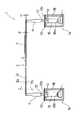
図示のように、当該物体搬送装置は、矩形板状に形成された振動体101と、この振動体101の長手方向一端側に設置されて該振動体101を励振する超音波励振手段130と、該超音波励振手段130とほぼ同様の構成を有して該振動体101の他端側に配置されたエネルギー変換手段131とを備えている。
【0004】
上記超音波励振手段130はホーン102を具備しており、上記振動体101は該ホーン102の先端に固着されている。
【0005】
なお、図において、ホーン102による超音波振動の方向を矢印Uにて示している。このように、ホーン102は縦振動を行う。振動体101の長さ(図の左右方向の寸法)及び幅(図で紙面に直角な方向の寸法)は、ホーン2から伝達される振動に基づく撓み振動の共振長に定められ、図で記号Tで示す撓み曲線のような振動をする。この撓み振動は振動体101の長さ方向及び幅方向において生じ、縞状の振動モードとなる。
【0006】
上記ホーン102は、振動体101に対する結合部とは反対側において振動子104と結合されている。この振動子104の電極104aと発振器105とが接続されており、振動子104は該発振器105によって駆動されて超音波振動を発する。ホーン102は、この振動子104が発する振動を機械的に増幅するものである。
【0007】
上記ホーン102にはフランジ部102bが形成されており、該ホーン102の下半部分及び上記振動子104を収容するケース106に対して、該フランジ部102bでパッキン102cを介して締結されている。
【0008】
一方、振動体101の他端側に配設されたエネルギー変換手段131は、搬送対象たる物体107を振動体101上で搬送させる搬送手段として作用するもので、超音波励振手段130により励振された振動体101が発する超音波のエネルギーを再び電気エネルギーに戻すべく変換する。
【0009】
具体的には、該エネルギー変換手段131が具備する振動子104の電極104aに、抵抗R及びコイルLからなる回路が接続されており、機械的エネルギーである超音波エネルギーより変換された電気エネルギーはこの回路を経ることによって更にジュール熱に変換され、放散される。
【0010】
上述した物体搬送装置においては、超音波励振手段130の作動によって振動体101が撓み振動を行い、該振動体101より音波が放射される。よって、物体107はこの音波の放射圧により振動体101上で僅かに浮揚する。
【0011】
この浮揚状態で上記エネルギー変換手段131が作動することによって、図で矢印Sにて示すように、振動体101に生ずる撓み振動の波が進行波となり、物体107はこの進行波に乗る状態にて搬送される。
【0012】
上記構成の物体搬送装置は、物体を完全に非接触の状態で搬送することが出来ると共に、次のような優位点を有する。
【0013】
▲1▼ 磁性体であるや否やなど、扱う物体の材質等の制約を受けることがなく、また、磁界中におくことができないもの等、あらゆる物体を搬送することができ、しかも、物体の重量及び寸法が比較的大きくとも対処可能である。
【0014】
▲2▼ 装置自体に関しては、実質的に、振動体とこれを励振する超音波励振手段を最小限設けるだけでよいから、小型化及びコストの低減が達成されると共に、消費電力も極めて少なくて済み、省エネルギー化に寄与する。
【0015】
▲3▼ 電気エネルギーを変換した音波の放射圧による浮揚作用であるため、作業者の安全性についても容易に確保し得ると共に、給電及びその断をなすことにより簡単に制御できる。
【0016】
上記した各優位点に鑑み、装置の実用化の一例として、液晶ディスプレイなどとして利用されるガラス基板やシリコンウェハーの搬送に利用することを考えている。何となれば、これらの品物は、その主たる面に対して塵埃(particle)が付着すること、および微細にても傷が発生することを可能な限り避けねばならないと同時に、磁場等に曝すことは厳禁とされる故である。
【0017】
ところで、近年、エレクトロニクス産業の発展に伴って上記ガラス基板及びシリコンウェハーの需要が増加し、その形状も大型化している。そこで、このような形状の大きい品物を搬送するためには、上述した物体搬送装置において振動体101を大きくすることが考えられ、実際に試作が行われた。
【0018】
【発明が解決しようとする課題】
しかしながら、この試作装置による搬送実験の結果、下記の問題が判明した。
【0019】
まず、実用化を目指すことを前提とした該試作装置においては、図10及び図11に示すように、円錐(corn)状のホーン102によって略一点に集中して伝達される振動を幅広な振動体101の全幅に均一に伝える必要があることから、ホーン102と振動体101との間に副振動体111が介装された。この副振動体111とは、有限要素法解析で先端面が均一な振動分布になるように設計されたプレート状のホーンである。
【0020】
ところが、ホーン102からは縦振動のみが付与されるにも拘らず、この副振動体111のポアソン(Poisson)比の影響によって横方向の振動が誘起され、これによって振動分布が不均一になり、きれいな進行波を得ることが難しい。
【0021】
また、図11に示すように、上記横方向の振動を抑圧すべく副振動体111にスリット111aが形成されたが、その効果は充分ではない。反面、このスリット111aを設けたことによって、同図で破線の矢印E1,E2にて示すように、振動体101の搬送経路中央部に対するとその両側部に対するとではエネルギーの伝達距離が大きく異なり、甚しい場合は正常な進行波(矢印W1にて示す)とは逆向きに進む波(矢印W2で示す)が両側で発生してしまい、振動体101の全幅にわたって同相の進行波を得ることは必ずしも容易ではない。
【0022】
他方、振動体101の大型化、すなわち、音波が放射される面積の増加によって、発生する音が大きくなり、この音を騒音レベル以下に抑えるための大掛りな遮音壁等を必要とし、コスト面から好ましくない。
【0023】
更に、大きな振動体101を振動させるためにはそのエネルギーのロスも大きく、この点、省エネルギー化の観点から解決されるべき問題となっている。
【0024】
本発明は上記した点に鑑みてなされたものであって、その主目的とするところは、形状の大きな物体を同相かつ均一な整った進行波に乗せて円滑に搬送することができ、また、遮音対策も無用か最小限で足り、しかも、エネルギーの利用効率が高い物体搬送装置を提供することである。
【0025】
また、本発明は、上記に加えて更に他の効果をも併せ奏し得る物体搬送装置を提供することも目的とする。
【0026】
【課題を解決するための手段】
上記主目的達成のために、本発明による物体搬送装置は、長手矩形板状の第1の振動体と第2の振動体とを進行方向に対して互いに平行に所定の距離離間させて配し、前記第1の振動体と第2の振動体の振動面を略同一平面に配し、前記第1の振動体と第2の振動体とを同時に励振する超音波励振手段と、物体を搬送させる搬送手段とを備え、前記第1の振動体の厚みは、物体搬送路の幅方向における中央側が厚肉に構成され、縁側が薄肉に構成されてなり、前記第2の振動体は前記前記第1の振動体と同一の構成を有し、前記第1の振動体と第2の振動体とは厚肉の中央側で対向し、前記第1の振動体と第2の振動体の放射圧は、物体搬送路の幅方向における両縁側が中央に比して大であるように設定され、
同時に励振される前記第1の振動体と第2の振動体との音波の放射圧により該振動体の表面上に被搬送物体を浮揚させ、搬送させるように構成されている。
【0027】
【発明の実施の形態】
本発明は、比較的大きな寸法のガラス基板やシリコンウェハー等を超音波の放射圧により浮揚させて搬送する場合に、整然とした進行波に乗せて搬送させると共に、騒音の発生とエネルギーの無駄な消費を極力抑えるために実施される。
【0028】
【実施例】
次に、本発明の実施例としての物体搬送装置を、添付図面を参照しながら説明する。
【0029】
図1乃至図4に示すように、この本発明に係る物体搬送装置は、2基の搬送ユニット1を互いに平行に並べてなる。両搬送ユニット1は全く同様に構成されている故、以下、片方の搬送ユニット1の説明を以て双方の搬送ユニットの説明に代える。但し、両搬送ユニット1の各構成部分について、互いに対応するものには同じ参照符号を付して示している。
【0030】
図1乃至図4に示すように、搬送ユニット1は、長手矩形板状に形成された振動体3を有しており、2基の搬送ユニット1が夫々具備する該振動体3は、夫々の振動面が略同一平面となるように平行に配されている。該振動体3は、搬送されるべき物体7をその表面上で浮揚させるためのものである。この振動体3の長手方向両端部には、副振動体4が各々結合されている。該副振動体4は、後述する超音波励振手段が発する縦振動を該振動体3に対して該振動体3の厚み方向で伝達すべく介装されたものである。
【0031】
上記振動体3は、その材質としてジュラルミン等が選定され、寸法としては、一例として、長さL(図2参照)が1029mm、幅B(図2及び図5参照)が70mm、厚みt(図3及び図5参照)が3mmに設定されている。
【0032】
また、副振動体4としては、有限要素法解析で先端面が均一な振動分布になるように設計されたプレート状のホーンが用いられ、振動体3の端部に対して複数のねじ9(図1及び図2に図示)を用いて締結してある。但し、振動体3と副振動体4の結合は、このようにねじによる他、接着、ロウ付け、溶接等によってもよい。
【0033】
上記副振動体4は、その下端部にて略円錐型のホーン12の先端部に結合されている。該ホーン12に対する副振動体4の取付けに関しても、上記ロウ付けや溶接など、種々の手段が用いられる。該ホーン12は略円錐形状であるが故に、後述する振動子が発する振動を略一点に集中して伝達するが、副振動体4はこの集中する振動を振動体3の全幅に、すなわち物体搬送路の幅方向において均一に拡散して伝える作用をなす。
【0034】
上記のホーン12は、上記振動体3の両端部に対応して配設された2つの超音波振動発生部14が夫々具備するものである。図1及び図2から明らかなように、該超音波振動発生部14は、隣り合う2基の搬送ユニット1に関して2つずつ、合計4つ設けられており、これら4つの超音波振動発生部14は図7に示す発振器15と共に超音波励振手段を構成する。但し、上記した副振動体4も、この超音波励振手段に含まれる。続いて、該超音波振動発生部14について詳述する。
【0035】
図3に示すように、該超音波振動発生部14において、上記ホーン12は、副振動体4に対する結合部とは反対側、すなわち下端側において振動子16と結合されている。この振動子16の電極16aと上記発振器15(図7参照)とが接続(接続の形態は後述する)されており、振動子16は該発振器15によって駆動されて超音波振動を発生する。ホーン12は、この振動子16が発する振動を機械的に増幅するものである。
【0036】
なお、図3において、ホーン12による超音波振動の振動方向を矢印Uにて示している。このように、ホーン12は縦振動を行う。
【0037】
また、上記ホーン12にはそのノーグルポイント部にフランジ部12bが形成されており、該ホーン12の下半部分と上記振動子16を収容するケース18に対して、該フランジ部12bにてパッキン12cを介して締結されている。
【0038】
かかる構成の物体搬送装置においては、上記ホーン12を通じて伝達される縦振動に基づき、振動体3がその長さ方向及び幅方向で撓み振動をする。すなわち、平面的には縞状の振動モードとなる。具体的には、駆動周波数は19.51kHzに設定され、該ホーン12の先端に締着したねじ9(図1及び図2参照)の頭部に10μmp−p程度の振動振幅がのせられる。
【0039】
ここで、平行に2基設けられた搬送ユニット1が各々具備する振動体3の形状について詳述する。
【0040】
図1乃至図6に示すように、両振動体3は長尺の矩形板状に形成され、特に図5及び図6から明らかなように、各々外側にして下面側にほぼ全長にわたって断面矩形状の切欠部3aが形成されている。但し、この切欠部3aは、副振動体4との結合部にまでは及んでいない。
【0041】
上記切欠部3aを形成したことにより、両振動体3は、物体搬送路の中央及びその両側に対応する各部位が夫々、厚肉部3b及び薄肉部3cとなっている。すなわち、両振動体3はその厚みが、物体搬送路の幅方向における中央から両縁側に向って段階的に小さくなるように変化している。この変化は、このように段階的に限らず、連続的、すなわちテーパ状に形成することによってもよい。
【0042】
図5において、上記切欠部3aの深さと幅は各々、0.2mm、20mmに設定されている。従って、振動体3の上記厚肉部3bの厚みは3mm(=t:前述)、幅は50mm(=B−20:〔B=70mm:前述〕)である。
【0043】
また、薄肉部3cの厚みは2.8mm(=3−0.2)、幅は20mmである。
【0044】
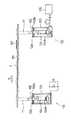
次に、当該物体搬送装置が備える2基の搬送ユニット1(図1等参照)について、図7に示す発振器15との接続の構成を説明する。
【0045】
なお、図7に示すように、この発振器15にはプラスの端子15aとマイナスの端子15bが各々2つずつ設けられ、このプラス及びマイナスで1組とされる端子が2基の搬送ユニット1の夫々に対して接続される。双方の搬送ユニット1と発振器15との接続は全く同様になされる故、図では1基の搬送ユニット1と発振器15に関する接続のみを示し、以下、これを説明し、他方の搬送ユニットとの接続状態の図示、説明は省略する。
【0046】
図7において、両振動子16が並列に設けられ、共に陰極が接地されている。同様に発振器15についても陰極が接地されている。発振器15の陽極はリレー21のスイッチ21aに接続されている。このリレー21の一方の端子21bは他のリレー22の一方の端子22bと共に片方の振動子16の陽極に接続されている。
【0047】
また、リレー21の他方の端子21cは該リレー22の他方の端子22cと共に他方の振動子16の陽極に接続されている。このリレー22のスイッチ22aには、並列に設けられた負荷抵抗R及び整合用インダクタンス(コイル)Lの各一端が接続され、該負荷抵抗R及びインダクタンスLの他端は接地されている。そして、図示のように、両リレー21及び22の各スイッチ21a,22aは互いに連動するようになされている。本例では、該負荷抵抗Rは300Ω、インダクタンスLは4.81mHとなされ、上記発振器15については55W〜85Wとされている。
【0048】
上記各スイッチ21a及び22aの切替えは、図1に示した2つのフォトセンサ24及び25から発せられる検知信号に基づいて行われる。これらのフォトセンサ24,25は夫々いわゆる反射型のもので、発光素子と受光素子とを内蔵し、該発光素子から発せられた照射光が搬送中の物体7の表面で反射し、この反射光が該受光素子に入射することによって該受光素子が上記検知信号としての受光出力を発する。
【0049】
なお、図1から明らかなように、上記両フォトセンサ24及び25は、振動体3による物体搬送路の搬送方向端よりも所定距離だけ手前側に配設されている。
【0050】
次に、上記した構成の物体搬送装置の動作を説明する。
【0051】
まず、図7において、両リレー21及び22の各スイッチ21a,22aが同図に示すように該両リレーの端子21c,22bに夫々接触している場合、一方の振動子16(図3も参照)が発振器15によって励振される。但し、図7には、前述したように片方の搬送ユニット(1:図1等参照)の作動部分のみが示されており、この振動子の励振は他方の搬送ユニットの作動部分(図示せず)においても同時に行われる。
【0052】
上記のように一方の振動子16が励振されることによって、両振動体3(図1等参照)が縞状振動モードにて振動を行い、該両振動体3の表面から音波が放射される。この状態で、図1乃至図4に示すように該両振動体3上に物体7が供給されると、該物体7はこの音波の放射圧によって該振動体3の表面から距離e1(図3に図示)を隔てた状態で浮揚する。
【0053】
図7に示す一方の振動子16(図3も参照)の振動によって物体7が上述のように振動体3上で浮揚するのと同時に、該振動体3の振動は同じく図7(図3も参照)に示す他の振動子16に伝わって、該振動子16によって機械的エネルギーである超音波エネルギーが電気エネルギーに変換される。この電気エネルギーは、図7に示す負荷抵抗R及びインダクタンスLからなる回路を経ることによって更にジュール熱に変換され、放散される。これにより、両振動体3に生ずる振動の波が進行波となり、物体7はこの進行波に乗る状態で矢印G(図1及び図3参照)にて示すように一方向へと搬送される。
【0054】
なお、上記エネルギー変換に関しては、詳しくは、電気エネルギーは負荷抵抗Rにてジュール熱に変換されて消費され、インダクタンスLはエネルギー変換の整合作用をなすもので、効率が最も大きくなる値に設定されている。
【0055】
上記のようにして物体7が矢印G方向に搬送されると、図1に示す2つのフォトセンサ24及び25による検知位置を次々と通過することになる。この場合、これら2つのフォトセンサ24及び25の両者から物体7の通過を示す検知信号が順に発せられる。マイクロプロセッサ等からなって当該物体搬送装置の作動制御を司る制御部(図示せず)は、これらフォトセンサ24,25からの各検知信号の順番によって物体の搬送方向を確認することができる。そして、該制御部は、これらのフォトセンサ24,25からの検知信号が共に得られたならば、図7に示した両リレー21及び22の各スイッチ21a,22aを切り替える。
【0056】
両リレー21,22の各スイッチ21a,22aが切り替えられて該両リレーの他方の端子21b,21cに夫々接触すると、進行波の向きが逆となり、物体7は減速して停止し、直ちに上記矢印G方向とは逆の方向に搬送される。この方向転換時、物体7はその慣性によって、停止までにある距離を走ることとなる。前述したように、上記両フォトセンサ24及び25を物体搬送路の搬送方向端よりも所定距離だけ手前側に配置したのはこのためである。これによって、物体7が物体搬送路をその慣性により行き過ぎて脱落することが防止される。
【0057】
上記から明らかなように、図7において、一方の振動子16が超音波エネルギーを発しているときに、他方の振動子16は、インダクタンスL及び負荷抵抗Rからなる回路と協働して該超音波エネルギーを電気エネルギーに変換して音波を進行波とするエネルギー変換手段として作用する。このエネルギー変換手段が、物体7を搬送させる搬送手段となる。
【0058】
なお、物体7を搬送させる搬送手段としては、上記のようなエネルギー変換手段に限らず、例えば、当該物体搬送装置全体を傾斜せしめて重力の作用によって搬送する方式や、圧搾空気を物体7の後から吹き付ける方式等、種々の構成のものが適用可能である。すなわち、物体7に推力を付与させればよい訳である。
【0059】
本実施例においては、上述のように、振動体3の長手方向両端に対応して2台の超音波振動発生部14(図1など参照)を配設し、該両超音波振動発生部14が発する超音波エネルギーについて選択的にエネルギー変換を行うことにより、物体7を往復搬送させることが可能となっている。
【0060】
なお、上記は、単に物体7の往復動についての説明であるが、物体7を所望の位置に停止させる場合、次のような制御が行われる。
【0061】
すなわち、一方向に向って搬送されている物体7について、その搬送の慣性力を打ち消すように上記のスイッチ21a,22aを切り替え、停止するまで逆方向の進行波を生じさせる。そして、物体7が停止したら、受動側すなわちエネルギー消費側の端子をオープン状態にし、定在波振動モードにするか、あるいは、駆動側である超音波振動発生側の駆動周波数をそれまでとは異なる共振点に変化させ、浮揚状態を保ったまま完全に停止させる。
【0062】
ところで、当該物体搬送装置においては、下記の構成によって、物体搬送路側方への物体7の逸脱が防止されている。
【0063】
すなわち、前述したように、両振動体3が、物体搬送路の中央及びその両側をなす厚肉部3bと薄肉部3cとを有している。つまり、両振動体3の厚みが、物体搬送路の幅方向における中央から両縁側に向って漸次変化、具体的には漸次小となるように設定されている。
【0064】
かかる構成を採用したことにより、図6にて多数の矢印で示すように、両振動体3が発する音波の放射圧は、物体搬送路の幅方向における両縁側が中央に比して大となる。
【0065】
この構成によれば、搬送中の物体7には、これを物体搬送路の中央に留めようとする力が常に作用し、該物体7が物体搬送路から側方に逸脱しようとすると該物体搬送路の両縁側の大きな放射圧により中央側へと押し戻される。よって、物体7は逸脱することなく物体搬送路の中心30(図2に図示)に沿って確実に搬送される。
【0066】
このような逸脱防止作用は、本実施例のように、物体搬送路の幅方向において振動体3の厚みに変化をもたせること等によって比較的簡単に実施できるからコストが安く済むものであり、しかも、当該物体搬送装置の構造の簡略化と小型化も併せて達成され、実用上非常に有効である。
【0067】
以上から明らかなように、当該物体搬送装置においては、複数、この場合2枚の振動体3をその各々の振動面が略同一平面となるように平行に配している。
【0068】
かかる構成によれば、個々の振動体3の幅寸法B(図2等参照)は小さくて済み、例えば副振動体4に関して言うなら、該副振動体4も幅の狭いものとなるからそのポアソン比やエネルギー伝達距離の相違等、振動体3の振動態様に悪影響を及ぼす因子は抑えられ、その結果、同相にして振動分布が均一な整った進行波が得られて物体7の搬送を円滑に行うことができる。
【0069】
より具体的には、各振動体3の幅寸法B(本実施例で70mmとしている)は、ホーン12より該振動体3の厚み方向に付与される縦振動の1波長の1/3以下に設定することにより、理想に近い結果が得られている。
【0070】
また、本発明に係る上記の構成では、1枚の振動体3とその励振をなすための超音波振動発生部14(振動子16を含む)とを1つのユニット(本実施例における各搬送ユニット1に相当)として製作すれば、このユニットの数を必要に応じて2基、3基、4基、…と適宜増やすことによって、かなり大きな物体まで広範な種類の物体に対処し得、汎用性に優れる。
【0071】
更に、本発明のように、幅の狭い振動体3を並設する構成では、その全体として発生する音のレベルも低くなり、遮音対策は不必要か、設けるとしても小規模のもので充分であり、コストが安く済む。
【0072】
また、幅の狭い振動体3では、消費する電力、すなわちエネルギーのロスも少なく、エネルギー利用効率が高い。
【0073】
なお、本実施例では、上述した如きユニット化を図るために、各振動体3に対して個別に超音波振動発生部14(振動子16を含む)を設けているが、これら2枚の振動体3を共通の超音波振動発生部によって励振させるようにしてもよい。
【0074】
ここで、前述した構成の物体搬送装置を使用して行った物体搬送実験の結果について説明する。
【0075】
<単位面積当たりの重量と浮揚距離との関係>
1枚の幅が70mmの振動板(前記振動体3)をレールのように2つ並列に並べ、駆動側のホーン振動振幅を互いに10μmp-p一定に保ち、アクリル板(160×160×板厚2mm、重量63.6g)及び、8インチシリコンウエハー(54.79g)を浮揚させ、駆動側のネジの近傍で浮揚距離を測定した結果を図8に示す。
【0076】
振動板の間隔を20mm〜70mm(最大幅160mm〜210mm)に広げることで、物体が音波を直接受ける部分の底面積が変化し、単位底面積当たりにかかる重量が変化するので、これをパラメータにして浮揚距離を測定した。図8から浮揚距離は、物体の単位底面積当たりの重量のほぼ−1乗に比例することが判明した。
【0077】
<振動板の幅と搬送速度の関係>
次に同じように、振動板の間隔を20mm〜70mm(最大幅160mm〜210mm)に広げることで、単位底面積当たりにかかる重量を可変させ、同物体の平均搬送速度を測定した結果を図9に示す。
【0078】
搬送速度は単位底面積当たりの重量に反比例することが確認出来た。また、浮揚に寄与する部分の底面積を変化させた場合、浮揚距離は大きく変化したが、平均搬送速度の変化率は少ないことが明らかになった。
【0079】
<まとめ>
進行波を励振させたたわみモード振動板を2枚用いて、非接触で大きい形状の物体を搬送する装置を試作した。その結果、次のことが明らかになった。
▲1▼振動板を2枚並列に用いることにより、振動板の幅より大きな形状の物体の非接触搬送が可能であること。この結果から、さらに大きな形状の物体を非接触搬送させる場合は、3連、4連と振動板を複数用いればよいこと。
▲2▼浮揚距離は、浮揚物体の単位底面積あたりの重量の−1乗に比例すること。
▲3▼搬送速度は、浮揚物体の単位底面積あたりの重量に反比例すること。
▲4▼最も安定した搬送が得られるのは、2つの振動板の幅と浮揚物体の幅が一致した場合であること。
【0080】
【発明の効果】
以上説明したように、本発明による物体搬送装置においては、複数の振動体をその各々の振動面が略同一平面となるように平行に配している。
かかる構成によれば、個々の振動体の幅寸法は小さくて済み、例えば副振動体におけるポアソン比やエネルギー伝達距離の相違等、振動体の振動態様に悪影響を及ぼす因子は抑えられ、その結果、同相にして振動分布が均一な整った進行波が得られて物体の搬送を円滑に行うことができる。
また、この構成では、1つの振動体とその励振をなすための超音波振動発生部とをユニット化すれば、該ユニットの数を必要に応じて増やすことによって、かなり大きな物体まで広範な種類の物体に対処し得、汎用性が高い。
更に、本発明のように、幅の狭い振動体を並設する構成では、その全体として発生する音のレベルも低くなり、遮音対策は不必要か、設けるとしても小規模のもので充分であり、コストが安く済む。
また、幅の狭い振動体では、消費する電力、すなわちエネルギーのロスも少なく、エネルギー利用効率が高い。
【図面の簡単な説明】
【図1】図1は、本発明の実施例としての物体搬送装置の要部の、一部断面を含む斜視図である。
【図2】図2は、図1に示した物体搬送装置の平面図である。
【図3】図3は、図1及び図2に示した物体搬送装置の、一部断面を含む正面図である。
【図4】図4は、図2に関するA−A矢視図である。
【図5】図5は、図3に関するC−C矢視図である。
【図6】図6は、図1乃至図3に示した物体搬送装置の一部の拡大図である。
【図7】図7は、図1乃至図3に示した物体搬送装置が具備するエネルギー変換部の回路図である。
【図8】図8は、本発明に係る物体搬送装置を用いて行われた搬送実験の結果を示すグラフである。
【図9】図9は、本発明に係る物体搬送装置を用いて行われた搬送実験の結果を示すグラフである。
【図10】図10は、従来の物体搬送装置の、一部断面を含む正面図である。
【図11】図11は、図10に示した物体搬送装置の一部を拡大した斜視図である。
【符号の説明】
1 搬送ユニット
3 振動体
4 副振動体
7 物体
12 ホーン
14 超音波振動発生部
15 発振器
16 振動子
21,22 リレー[0001]
BACKGROUND OF THE INVENTION
The present invention relates to an object conveying apparatus including an object levitation apparatus that levitates an object in the air using ultrasonic radiation pressure.
[0002]
[Prior art]
Conventionally, as this type of apparatus, there is one disclosed in Japanese Patent Application Laid-Open No. 7-187388 related to the applicant of the present application. FIG. 10 shows an object conveying apparatus which is a part of the disclosure content of the publication.
[0003]
As shown in the figure, the object conveying apparatus includes a vibrating
[0004]
The ultrasonic excitation means 130 includes a
[0005]
In the figure, the direction of ultrasonic vibration by the
[0006]
The
[0007]
The
[0008]
On the other hand, the
[0009]
Specifically, a circuit composed of a resistor R and a coil L is connected to the
[0010]
In the object conveying apparatus described above, the vibrating
[0011]
When the energy conversion means 131 operates in this levitation state, as shown by an arrow S in the figure, a wave of flexural vibration generated in the
[0012]
The object conveying apparatus having the above configuration can convey an object in a completely non-contact state, and has the following advantages.
[0013]
(1) As long as it is a magnetic material, it is not subject to restrictions such as the material of the object to be handled, and can carry any object such as one that cannot be placed in a magnetic field, and the weight of the object Even if the size is relatively large, it can be dealt with.
[0014]
(2) With respect to the device itself, since it is only necessary to provide a vibrating body and ultrasonic excitation means for exciting the vibrating body, it is possible to achieve downsizing and cost reduction and extremely low power consumption. Contributes to energy saving.
[0015]
{Circle around (3)} Since it is a levitation action due to the radiation pressure of sound waves converted from electric energy, it is possible to easily ensure the safety of the operator, and it is possible to easily control by supplying power and disconnecting it.
[0016]
In view of the above-mentioned advantages, as an example of practical application of the apparatus, it is considered to be used for transporting a glass substrate or a silicon wafer used as a liquid crystal display or the like. Under these circumstances, it is necessary to avoid as much as possible that these articles have dust (particles) attached to their main surface, and even if they are fine, they should not be exposed to magnetic fields. Because it is strictly prohibited.
[0017]
By the way, in recent years, with the development of the electronics industry, the demand for the glass substrate and the silicon wafer has increased, and the size of the glass substrate and the silicon wafer has increased. Therefore, in order to convey such a large-sized article, it is conceivable to enlarge the vibrating
[0018]
[Problems to be solved by the invention]
However, the following problems were found as a result of the transport experiment using this prototype device.
[0019]
First, in the prototype device premised on the practical use, as shown in FIGS. 10 and 11, the vibration transmitted concentratedly at one point by the cone-
[0020]
However, although only the longitudinal vibration is applied from the
[0021]
Further, as shown in FIG. 11, the slit 111 a is formed in the
[0022]
On the other hand, due to the increase in the size of the
[0023]
Furthermore, in order to vibrate the large vibrating
[0024]
The present invention has been made in view of the above points, and the main purpose of the present invention is to smoothly transport an object having a large shape on a traveling wave having the same phase and uniformity, The object of the present invention is to provide an object conveying apparatus that requires no or minimal noise insulation measures and has high energy utilization efficiency.
[0025]
It is another object of the present invention to provide an object conveying apparatus that can achieve other effects in addition to the above.
[0026]
[Means for Solving the Problems]
In order to achieve the above main object, the object conveying apparatus according to the present invention has a long rectangular plate shape.The first vibrating body and the second vibrating bodyParallel to the direction of travelThe first vibrating body and the second vibrating body are spaced apart from each other by a predetermined distance.Arrange the vibration surface on the same plane,The first vibrator and the second vibratorAn ultrasonic excitation means for exciting simultaneously and a conveying means for conveying an object;Of the first vibratorThickness is the center in the width direction of the object transport path~ sideIs configured to be thick, and the edge side is configured to be thin.The first vibrating body has the same configuration as the first vibrating body, and the first vibrating body and the second vibrating body are opposed to each other at the center of the thick wall, and the first vibrating body and the second vibrating body areThe radiation pressure is set so that both edges in the width direction of the object transport path are larger than the center.,
The first vibrator and the second vibrator simultaneously excited;On the surface of the vibrating body by the radiation pressure ofConveyed objectIs configured to float and transport.
[0027]
DETAILED DESCRIPTION OF THE INVENTION
In the present invention, when a glass substrate or silicon wafer having a relatively large size is levitated and conveyed by ultrasonic radiation pressure, it is carried on an orderly traveling wave, and noise is generated and energy is wasted. It is carried out to suppress as much as possible.
[0028]
【Example】
Next, an object conveying apparatus as an embodiment of the present invention will be described with reference to the accompanying drawings.
[0029]
As shown in FIGS. 1 to 4, the object conveying apparatus according to the present invention has two conveying
[0030]
As shown in FIG. 1 to FIG. 4, the
[0031]
As the material of the vibrating
[0032]
Further, as the
[0033]
The
[0034]
The
[0035]
As shown in FIG. 3, in the ultrasonic
[0036]
In FIG. 3, the vibration direction of ultrasonic vibration by the
[0037]
Further, the
[0038]
In the object transporting apparatus having such a configuration, the vibrating
[0039]
Here, the shape of the
[0040]
As shown in FIGS. 1 to 6, both vibrating
[0041]
By forming the
[0042]
In FIG. 5, the depth and width of the
[0043]
The
[0044]
Next, the connection configuration of the
[0045]
As shown in FIG. 7, the
[0046]
In FIG. 7, both
[0047]
The
[0048]
The
[0049]
As is clear from FIG. 1, both the
[0050]
Next, the operation of the object conveying apparatus having the above-described configuration will be described.
[0051]
First, in FIG. 7, when the
[0052]
When one
[0053]
At the same time that the
[0054]
Regarding the energy conversion, in detail, the electric energy is converted to Joule heat by the load resistance R and consumed, and the inductance L has an energy conversion matching function, and is set to a value that maximizes the efficiency. ing.
[0055]
When the
[0056]
When the
[0057]
As is apparent from the above, in FIG. 7, when one
[0058]
The transport means for transporting the
[0059]
In the present embodiment, as described above, two ultrasonic vibration generators 14 (see FIG. 1 and the like) are arranged corresponding to both ends in the longitudinal direction of the vibrating
[0060]
Note that the above is merely a description of the reciprocating motion of the
[0061]
That is, for the
[0062]
By the way, in the said object conveyance apparatus, the deviation of the
[0063]
That is, as described above, both vibrating
[0064]
By adopting such a configuration, as indicated by a large number of arrows in FIG. 6, the radiation pressure of sound waves generated by both
[0065]
According to this configuration, a force that keeps the
[0066]
Such a deviating prevention function can be carried out relatively easily by changing the thickness of the vibrating
[0067]
As is apparent from the above, in the object transporting apparatus, a plurality of, in this case, two vibrating
[0068]
According to such a configuration, the width B (see FIG. 2 and the like) of each vibrating
[0069]
More specifically, the width B (70 mm in this embodiment) of each vibrating
[0070]
Further, in the above-described configuration according to the present invention, one vibrating
[0071]
Further, in the configuration in which the
[0072]
In addition, the narrow vibrating
[0073]
In the present embodiment, in order to achieve unitization as described above, an ultrasonic vibration generating unit 14 (including the vibrator 16) is individually provided for each vibrating
[0074]
Here, the result of the object conveyance experiment performed using the object conveyance apparatus having the above-described configuration will be described.
[0075]
<Relationship between weight per unit area and levitation distance>
Two diaphragms (the vibrating body 3) having a width of 70 mm are arranged in parallel like a rail, and the horn vibration amplitude on the driving side is 10 μm each other.ppFig. 3 shows the result of measuring the levitation distance in the vicinity of the screw on the drive side, keeping the surface constant, levitating an acrylic plate (160 x 160 x
[0076]
By expanding the distance between the diaphragms to 20 mm to 70 mm (
[0077]
<Relationship between diaphragm width and conveyance speed>
Next, similarly, the distance between the diaphragms is increased to 20 mm to 70 mm (
[0078]
It was confirmed that the conveyance speed was inversely proportional to the weight per unit bottom area. It was also found that when the bottom area of the part that contributes to levitation was changed, the levitation distance changed significantly, but the rate of change in average transport speed was small.
[0079]
<Summary>
A prototype of a non-contact, large-shaped object transporter was fabricated using two flexure mode diaphragms excited by traveling waves. As a result, the following became clear.
(1) Non-contact conveyance of an object having a shape larger than the width of the diaphragm is possible by using two diaphragms in parallel. From this result, when a larger-sized object is conveyed in a non-contact manner, it is sufficient to use a triple, a quadruple, and a plurality of diaphragms.
(2) The levitation distance shall be proportional to the weight minus the weight of the floating object per unit bottom area.
(3) The transport speed must be inversely proportional to the weight per unit bottom area of the floating object.
(4) The most stable conveyance can be obtained when the width of the two diaphragms matches the width of the floating object.
[0080]
【The invention's effect】
As described above, in the object transporting apparatus according to the present invention, a plurality of vibrating bodies are arranged in parallel so that their vibrating surfaces are substantially on the same plane.
According to such a configuration, the width dimension of each vibrating body may be small, for example, factors that adversely affect the vibration mode of the vibrating body, such as a difference in Poisson's ratio and energy transmission distance in the sub-vibrating body, can be suppressed. A traveling wave having the same phase and a uniform vibration distribution can be obtained, and the object can be transported smoothly.
In addition, in this configuration, if one vibration body and an ultrasonic vibration generating unit for exciting the same are unitized, a wide variety of objects can be obtained up to a considerably large object by increasing the number of units as necessary. It can deal with objects and is highly versatile.
Further, in the configuration in which narrow vibrators are arranged side by side as in the present invention, the level of the sound generated as a whole becomes low, and a sound insulation measure is unnecessary, or even a small-scale one is sufficient. Cost is low.
In addition, a narrow vibrating body has little energy loss, that is, energy loss, and high energy utilization efficiency.
[Brief description of the drawings]
FIG. 1 is a perspective view including a partial cross section of a main part of an object conveying apparatus as an embodiment of the present invention.
FIG. 2 is a plan view of the object conveying apparatus shown in FIG.
FIG. 3 is a front view including a partial cross section of the object transporting apparatus shown in FIGS. 1 and 2;
4 is an AA arrow view of FIG. 2. FIG.
5 is a view taken along the line CC of FIG. 3. FIG.
FIG. 6 is an enlarged view of a part of the object conveying apparatus shown in FIGS. 1 to 3;
FIG. 7 is a circuit diagram of an energy conversion unit included in the object conveying device shown in FIGS. 1 to 3;
FIG. 8 is a graph showing the results of a transport experiment performed using the object transport apparatus according to the present invention.
FIG. 9 is a graph showing the results of a transport experiment performed using the object transport apparatus according to the present invention.
FIG. 10 is a front view including a partial cross section of a conventional object conveying apparatus.
11 is an enlarged perspective view of a part of the object conveying apparatus shown in FIG.
[Explanation of symbols]
1 Transport unit
3 Vibration body
4 Sub-vibrator
7 objects
12 Horn
14 Ultrasonic vibration generator
15 Oscillator
16 transducers
21,22 Relay
Claims (1)
Translated fromJapanese前記第1の振動体と第2の振動体とを同時に励振する超音波励振手段と、
物体を搬送させる搬送手段とを備え、
前記第1の振動体の厚みは、物体搬送路の幅方向における中央側が厚肉に構成され、縁側が薄肉に構成されてなり、前記第2の振動体は前記前記第1の振動体と同一の構成を有し、前記第1の振動体と第2の振動体とは厚肉の中央側で対向し、
前記第1の振動体と第2の振動体の放射圧は、物体搬送路の幅方向における両縁側が中央に比して大であるように設定され、
同時に励振される前記第1の振動体と第2の振動体との音波の放射圧により該振動体の表面上に被搬送物体を浮揚させ、搬送させること
を特徴とする物体搬送装置。A longitudinal rectangular plate-likefirst vibrating body and a second vibrating body arearranged in parallel with each other at apredetermined distance from each otherin a traveling direction,and vibration surfaces ofthe first vibrating body and the second vibrating body are arranged. In an object transporting device that is arranged on substantially the same plane,
Ultrasonic excitation means for excitingthe first vibrating body and the second vibrating body simultaneously;
A conveying means for conveying an object,
The thickness of the first vibrating body is configured such that the centerside in the width direction of the object conveyance path is thick and the edge side is thin, and the second vibrating body isthe same as the first vibrating body. Having the same configuration, the first vibrating body and the second vibrating body are opposed to each other on the thick center side;
The radiation pressures ofthe first vibrating body and the second vibrating body are set so that both edge sides in the width direction of the object conveyance path are larger than the center,
An object conveying apparatus characterized in that an object tobe conveyed is levitated andconveyed on the surfaceof the vibrating body by radiation pressure of sound waves ofthe first vibrating body and the second vibrating body excited simultaneously .
Priority Applications (1)
| Application Number | Priority Date | Filing Date | Title |
|---|---|---|---|
| JP03126196AJP3948636B2 (en) | 1996-01-25 | 1996-01-25 | Object conveying device provided with object levitation device |
Applications Claiming Priority (1)
| Application Number | Priority Date | Filing Date | Title |
|---|---|---|---|
| JP03126196AJP3948636B2 (en) | 1996-01-25 | 1996-01-25 | Object conveying device provided with object levitation device |
Publications (2)
| Publication Number | Publication Date |
|---|---|
| JPH09202425A JPH09202425A (en) | 1997-08-05 |
| JP3948636B2true JP3948636B2 (en) | 2007-07-25 |
Family
ID=12326415
Family Applications (1)
| Application Number | Title | Priority Date | Filing Date |
|---|---|---|---|
| JP03126196AExpired - Fee RelatedJP3948636B2 (en) | 1996-01-25 | 1996-01-25 | Object conveying device provided with object levitation device |
Country Status (1)
| Country | Link |
|---|---|
| JP (1) | JP3948636B2 (en) |
Cited By (1)
| Publication number | Priority date | Publication date | Assignee | Title |
|---|---|---|---|---|
| WO2024170419A1 (en)* | 2023-02-14 | 2024-08-22 | Isra Vision Gmbh | Device for inspecting a planar or web-shaped object |
Families Citing this family (13)
| Publication number | Priority date | Publication date | Assignee | Title |
|---|---|---|---|---|
| JP3928343B2 (en) | 2000-09-20 | 2007-06-13 | 株式会社豊田自動織機 | Control method for object levitation apparatus and object levitation apparatus |
| US6802220B2 (en) | 2000-10-26 | 2004-10-12 | Kabushiki Kaisha Toyota Jidoshokki | Apparatus for transporting levitated objects |
| JP3931552B2 (en) | 2000-11-07 | 2007-06-20 | 株式会社豊田自動織機 | Object levitation transfer device |
| JP4003568B2 (en)* | 2001-07-27 | 2007-11-07 | 株式会社豊田自動織機 | Object levitation device, object transport device, and unloading device |
| JP3804512B2 (en) | 2001-10-26 | 2006-08-02 | 株式会社豊田自動織機 | Power supply unit for vibrator drive |
| JP4001136B2 (en)* | 2003-11-13 | 2007-10-31 | 株式会社豊田自動織機 | Sonic levitation device |
| JP2008143641A (en)* | 2006-12-08 | 2008-06-26 | Shinko Electric Co Ltd | Vibrating type conveyor |
| DE102008057389B4 (en) | 2008-11-14 | 2011-03-17 | Fraunhofer-Gesellschaft zur Förderung der angewandten Forschung e.V. | Transporting an object over a surface |
| KR101520744B1 (en)* | 2013-11-04 | 2015-05-15 | 코닝정밀소재 주식회사 | Non-contact vibration cut device and method of processing an object |
| KR20170085543A (en)* | 2014-11-17 | 2017-07-24 | 코닝 인코포레이티드 | Ultrasonic near field hot glass transportation and forming |
| KR102353752B1 (en)* | 2018-10-31 | 2022-01-20 | 마이크로·텍 가부시끼가이샤 | Vibration device, vibration method, screen printing device, vibration input device and material handling device |
| CN109516218A (en)* | 2019-01-22 | 2019-03-26 | 北京理工大学 | A kind of ultrasonic phase array of antiradar reflectivity |
| CN110356852B (en)* | 2019-08-19 | 2021-02-05 | 哈尔滨工业大学 | Ultrasonic long-distance suspension transmission device and supporting distance determination method |
Family Cites Families (4)
| Publication number | Priority date | Publication date | Assignee | Title |
|---|---|---|---|---|
| JPS62268141A (en)* | 1986-05-16 | 1987-11-20 | Kishimoto Sangyo Kk | Method and apparatus for preventing deviation from carrier path of body to be fed in conveyor for semiconductor wafer |
| JPS63208419A (en)* | 1987-02-26 | 1988-08-29 | Matsushita Electric Ind Co Ltd | free flow conveyor |
| JP2934374B2 (en)* | 1993-11-11 | 1999-08-16 | 株式会社カイジョー | Object transfer device equipped with object levitation device and object transfer method |
| JP3300145B2 (en)* | 1993-12-24 | 2002-07-08 | 株式会社カイジョー | Object levitation device |
- 1996
- 1996-01-25JPJP03126196Apatent/JP3948636B2/ennot_activeExpired - Fee Related
Cited By (1)
| Publication number | Priority date | Publication date | Assignee | Title |
|---|---|---|---|---|
| WO2024170419A1 (en)* | 2023-02-14 | 2024-08-22 | Isra Vision Gmbh | Device for inspecting a planar or web-shaped object |
Also Published As
| Publication number | Publication date |
|---|---|
| JPH09202425A (en) | 1997-08-05 |
Similar Documents
| Publication | Publication Date | Title |
|---|---|---|
| JP3948636B2 (en) | Object conveying device provided with object levitation device | |
| JP3300145B2 (en) | Object levitation device | |
| JP3931552B2 (en) | Object levitation transfer device | |
| JP2802883B2 (en) | Object levitating device, object conveying device equipped with the device, and object levitating method | |
| JP3804512B2 (en) | Power supply unit for vibrator drive | |
| JPH07137824A (en) | Object floating device, object conveying device therewith, and method of floating object | |
| JPH09169427A (en) | Floating device and board carrying device provided with this floating device | |
| JP2934379B2 (en) | Object transfer device with object levitation device | |
| JP3474674B2 (en) | Object transfer device equipped with an object levitation device | |
| JP3928343B2 (en) | Control method for object levitation apparatus and object levitation apparatus | |
| JP3967855B2 (en) | Object levitation device | |
| JP2934374B2 (en) | Object transfer device equipped with object levitation device and object transfer method | |
| JP4048313B2 (en) | Object levitation device | |
| JP2005239391A (en) | Object levitation device and object levitation carrying device | |
| KR100636590B1 (en) | Object levitating apparatus by sonic waves | |
| JP3864688B2 (en) | Object levitation device | |
| JP3975666B2 (en) | Object levitation device | |
| JP2005119839A (en) | Object floating device | |
| JP2000279888A (en) | Ultrasonic cleaner | |
| JP4055341B2 (en) | Object levitation device | |
| JPH07137823A (en) | Object floating device, object floating bearing, object conveying device and object floating method using the same | |
| KR100731411B1 (en) | Apparatus for floating and loading/unloading objects | |
| JP2001097529A (en) | Body floating device | |
| JP2001097531A (en) | Body floating method, unloading method, body carrying method, and body floating device and unloading device | |
| JP2005112517A (en) | Object levitating and transporting device |
Legal Events
| Date | Code | Title | Description |
|---|---|---|---|
| A02 | Decision of refusal | Free format text:JAPANESE INTERMEDIATE CODE: A02 Effective date:20040206 | |
| A521 | Written amendment | Free format text:JAPANESE INTERMEDIATE CODE: A523 Effective date:20040402 | |
| A911 | Transfer of reconsideration by examiner before appeal (zenchi) | Free format text:JAPANESE INTERMEDIATE CODE: A911 Effective date:20040407 | |
| A912 | Removal of reconsideration by examiner before appeal (zenchi) | Free format text:JAPANESE INTERMEDIATE CODE: A912 Effective date:20040514 | |
| A521 | Written amendment | Free format text:JAPANESE INTERMEDIATE CODE: A523 Effective date:20061225 | |
| A521 | Written amendment | Free format text:JAPANESE INTERMEDIATE CODE: A821 Effective date:20061226 | |
| A61 | First payment of annual fees (during grant procedure) | Free format text:JAPANESE INTERMEDIATE CODE: A61 Effective date:20070413 | |
| R150 | Certificate of patent or registration of utility model | Free format text:JAPANESE INTERMEDIATE CODE: R150 | |
| FPAY | Renewal fee payment (event date is renewal date of database) | Free format text:PAYMENT UNTIL: 20110427 Year of fee payment:4 | |
| FPAY | Renewal fee payment (event date is renewal date of database) | Free format text:PAYMENT UNTIL: 20120427 Year of fee payment:5 | |
| LAPS | Cancellation because of no payment of annual fees |