JP3948328B2 - Electronic camera rental service system - Google Patents
Electronic camera rental service systemDownload PDFInfo
- Publication number
- JP3948328B2 JP3948328B2JP2002104699AJP2002104699AJP3948328B2JP 3948328 B2JP3948328 B2JP 3948328B2JP 2002104699 AJP2002104699 AJP 2002104699AJP 2002104699 AJP2002104699 AJP 2002104699AJP 3948328 B2JP3948328 B2JP 3948328B2
- Authority
- JP
- Japan
- Prior art keywords
- image
- image data
- electronic camera
- identification information
- camera
- Prior art date
- Legal status (The legal status is an assumption and is not a legal conclusion. Google has not performed a legal analysis and makes no representation as to the accuracy of the status listed.)
- Expired - Fee Related
Links
Images


Landscapes
- Facsimiles In General (AREA)
- Studio Devices (AREA)
- Management, Administration, Business Operations System, And Electronic Commerce (AREA)
- Television Signal Processing For Recording (AREA)
Description
Translated fromJapanese【0001】
【発明の属する技術分野】
本発明は、撮影した画像データをネットワーク上の画像サーバに格納して利用するのに好適な電子カメラのレンタルサービスシステムに関する。
【0002】
【従来の技術】
従来、電子カメラを利用したレンタルサービスシステムとして、テーマパークや遊園地などにおいて、入場時に利用者に電子カメラを貸し出し、退場時に利用者が撮影した画像データのプリントや画像データを記録したCD−Rのような記憶媒体を利用者に渡すサービスが知られている。
【0003】
【発明が解決しようとする課題】
しかしながら上記のような従来の電子カメラのレンタルサービスシステムにおいては、利用者は電子カメラを返却した時にプリントやCD−R等が荷物として増えてしまうので、その後身軽に遊歩やショッピングを楽しむことができなかった。また汎用の電子カメラを貸し出した場合には、不心得者に貸し出した電子カメラを盗難されて一般使用される可能性があり、盗難防止のための高額なデポジットを利用者から預かったり、複雑な盗難防止システムを構築する必要があった。そのため利用者にとって利用しにくいレンタルサービスシステムになってしまい、営業的な成功には結びつかなかった。
【0004】
そこで本発明は、電子カメラの返却時にプリント等の荷物が増えないとともに、低コストかつ簡便に電子カメラの盗難を防止できる電子カメラのレンタルサービスシステムを提供することを目的とする。
【0005】
【課題を解決するための手段】
上記目的を達成するため、本発明による電子カメラのレンタルサービスシステムにおいては、利用者が電子カメラで撮影した画像データを外部の画像管理サーバ上の利用者がアクセスできない受信画像メモリ(バッファメモリ)に無線送信により転送して一時的に格納するとともに、電子カメラの返却時に受信画像メモリに格納した画像データを利用者がアクセス可能な閲覧画像メモリに移動し、該閲覧画像メモリに移動した画像データへのアクセス情報を利用者に通知する。利用者は該アクセス情報に基づいて外部の画像管理サーバに接続して自分の撮影した画像データにアクセスして、携帯電話等のユーザ端末で画像データを閲覧したり、自宅のパソコン等に画像データをダウンロードする。
【0006】
【発明の実施の形態】
以下、図面を参照して本発明の実施形態について説明する。図1は本発明による電子カメラのレンタルサービスシステムの概念図であって、まず利用者はレンタルサービス会社のサービスショップ170から電子カメラ100の貸し出しを受ける。貸し出し時にサービスショップ170は利用者からいくらかのデポジットを受け取ってもよい。利用者は貸し出しされた電子カメラ100を用いて撮影を行う。電子カメラ100で撮影された画像データは電子カメラ100に内蔵された通信機能によりレンタルサービス会社の画像管理サーバ150に送信される。なお画像データは電子カメラ100のカメラ識別情報が付けられ電子カメラ100から画像送信コマンドにより画像管理サーバ150に送られ、画像管理サーバ150は画像送信コマンドを受信すると、後述するように受信したカメラ識別情報に応じて画像データを保存する。このとき保存された画像データは外部からの読み出しが禁止されている。
【0007】
利用者は何枚かの撮影を終了すると電子カメラ100をサービスショップ180に返却する。貸し出し時のサービスショップ170と返却時のサービスショップ180は必ずしも同一である必要はない。サービスショップ180は電子カメラ100に記録された撮影枚数に応じて利用者に料金を請求する。サービスショップ180は料金支払いが完了すると電子カメラ100から読み取ったカメラ識別情報をサービス端末140から返却完了コマンドにより画像管理サーバ150に送信する。画像管理サーバ150はサービス端末140から返却完了コマンドを受信すると、受信したカメラ識別情報に応じた画像データを新規に生成した閲覧識別情報に対応させて格納し、該画像データを読み出し許可するとともに、サービス端末140に該閲覧識別情報を送信する。サービス端末140は画像管理サーバ150から閲覧識別情報を受信すると、利用者が画像管理サーバ150に保存された画像データへアクセスするために必要なアクセス情報(画像管理サーバ150へのサーバアクセス情報、画像データを閲覧するための閲覧識別情報等)を利用者に印刷して渡す。
【0008】
利用者はサービス端末140から受け取ったアクセス情報に応じて携帯電話等のユーザ端末160から画像管理サーバ150にアクセスし、画像閲覧コマンドにより閲覧識別情報を画像管理サーバ150に送る。画像管理サーバ150は画像閲覧コマンドを受信すると、受信した閲覧識別情報に応じて画像データをユーザ端末160に送信する。利用者はユーザ端末160で受信した画像データをユーザ端末160に備えられた表示画面に表示して閲覧する。
【0009】
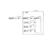
図2は本発明による電子カメラのレンタルサービスシステムの構成図であって、電子カメラ100は無線通信機能(無線電話機能)を備えており、無線携帯電話回線190により基地局120経由でインターネット130に接続している。サービス端末140および画像管理サーバ150は通信回線によりインターネット130に接続している。ユーザ端末160は無線通信機能(無線電話機能)を備えており、無線携帯電話回線190により基地局120経由でインターネット130に接続している。電子カメラ100は撮影した画像データを無線携帯電話回線190により基地局120経由でインターネット130上の画像管理サーバ150に送信する。またサービス端末140は電子カメラ100の返却時に返却処理に必要な情報をインターネット130経由で画像管理サーバ150とやりとりする。ユーザ端末160はインターネット130上の画像管理サーバ150から画像データを無線携帯電話回線190により基地局120経由でダウンロードする。
【0010】
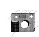
図3および図4は、本発明に用いられる電子カメラ100の一実施形態の外観図(正面視および背面視)である。図1に示すように電子カメラ100の前面には被写体像を形成するための撮影レンズ10、撮影画面を確認するためのファインダ11、撮影時に被写体を照明するためのストロボ12、被写体の明るさを検知するための測光回路13、電子カメラ100をユーザが手でホールドしやすくするためにカメラ本体から出っ張ったグリップ部14が備えられ、上面には撮影を指示するためのレリーズボタン16、電子カメラ100の電源のON/OFF制御を行うための電源スイッチ17が備えられ、側面にはサービス端末と通信するための接続ケーブルを装着するための接続端子15が備えられる。
【0011】
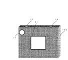
図4に示すように、電子カメラ100の背面にはファインダ11の接眼部、テキストおよび画像表示用の略四角形の画面を備えたLCD(画面)21が配置されている。
【0012】
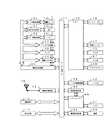
図5は、図3および図4に示した電子カメラ100の内部の電気構成例を示すブロック図であって、各構成要素は各種情報データおよび制御データを伝送するためのデータ/制御バス51を介して互いに接続されている。CPU50(中央処理ユニット)は電子カメラ100全体の制御を行う手段であって、シャッターボタン16、電源スイッチ17、測光回路13からの入力情報に応じて撮影制御回路60、画面制御回路92、電源制御回路64への各種指示を行う。測光回路13は被写体の輝度を測定し、その測定結果である測光データをCPU50に出力する。CPU50は測光データに応じて、CCD55の露光時間と感度をCCD駆動回路56により設定するとともに、該設定に応じて撮影制御回路60を介し絞り53の絞り値を絞り制御回路54により制御する。CPU50は測光データに基づき被写体輝度が所定値以下であると判断した場合には撮影時にストロボ駆動回路73によりストロボ12を発光させる。
【0013】
CPU50はレリーズボタン16の操作に応じて撮影制御回路60を介し撮影動作を制御する。CPU50は、ROM67(リードオンリメモリ)に記憶されている制御プログラムに従い各部を制御する。EEPROM68(電気的消去書き込み可能ROM)は不揮発性のメモリであって、電子カメラ100の動作に必要な設定情報等を記憶している。RAM70は揮発性のメモリであって、CPU50の一時的作業領域として用いられる。CPU50は、電源スイッチ17の操作状態を検知して、電源制御回路64を介して電源63の制御を行う。CPU50は通信端子15に接続された不図示の通信ケーブルを介しサービス端末140と情報のやりとりを行う。
【0014】
撮影制御回路60は、レンズ駆動回路52により撮影レンズ10のフォーカシングを行い、絞り制御回路54により絞り53を制御してCCD55の露光量をコントロールし、CCD駆動回路56によりCCD55の動作を制御する。被写体からの光束は撮影レンズ10により光量調節のための絞り53を介し、CCD55上に被写体像として形成され、この被写体像はCCD55により撮像される。複数の画素を備えたCCD55(チャージカップルドデバイス)は被写体像を撮像するための電荷蓄積型イメージセンサーであり、CCD55上に形成された被写体像の強度に応じた電気的な画像信号をCCD駆動回路56により供給される駆動パルスに応じてアナログ処理部57に出力する。
【0015】
アナログ処理部57はCCD55が光電変換した画像信号を所定のタイミングでサンプリングし、そのサンプリングした信号を所定のレベルに増幅する。A/D変換回路58(アナログデジタル変換回路)はアナログ処理部57でサンプリングした画像信号をデジタル化することによりデジタルデータに変換し、撮影バッファメモリ59は該デジタルデータを一旦格納する。
【0016】
撮影制御回路60は上述の動作を繰り返すとともに、画面制御回路92はデータ/制御バス51を介して撮影バッファメモリ59に順次格納されるデジタルデータを読み出してフレームメモリ69に一旦格納し、該デジタルデータを表示用画像データに変換してフレームメモリ69に再格納し、該表示用画像データをLCD21に表示させるというスルー画像表示動作を繰り返す。このようにして、LCD21にCCD50により撮像されている画像がリアルタイムに表示されるので、このスルー画像をモニター画面として使用して撮影のための構図設定を行うことが可能になる。撮影制御回路60は撮影バッファメモリ59に格納したデジタルデータの高周波成分の度合い解析して撮影レンズ10の焦点調節状態を検出し、検出結果に応じてレンズ駆動回路52により撮影レンズ10の焦点調節を行う。
【0017】
レリーズ時に撮影制御回路60はCPU50から撮影指示を受けると、CCD駆動回路56を介してCCD55により被写体像を撮像させ、撮像により生成した画像信号をアナログ処理部57、A/D変換回路58を介して撮影バッファメモリ59にデジタルデータ(生データ)として一旦格納する。撮影制御回路60は撮影バッファメモリ59に一旦格納したデジタルデータを所定の記録フォーマット(JPEGなど)に変換または圧縮して画像データを形成し、該画像データを無線通信回路72とアンテナ76を介しインターネット上の画像管理サーバ150に送信する。
【0018】
図6はEEPROM68に記憶される情報の構成を示す図であって、電子カメラ100の個体を識別するためのカメラ識別情報と画像データを送信する画像管理サーバ150の宛先を示すサーバアクセス情報と撮影枚数を記録するための撮影枚数情報とからなる。
【0019】
図7はサービス端末140の構成を示す図であって、制御手段141が後述する各手段を統合して制御する。第1通信手段142はインターネット上の画像管理サーバ150に接続して各種情報のやりとりを行う。第2通信手段143は不図示の通信ケーブルを介して電子カメラ100と接続し、各種情報のやりとりを行う。演算手段144は撮影枚数情報に応じて料金の計算を行う。入力手段145はオペレータからの指示を入力する。表示手段146は料金の表示などに用いられる。印刷手段147は利用者に手渡される画像管理サーバ150へのアクセス情報や画像データをダウンロードするための閲覧識別情報を印刷する。
【0020】
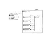
図8は画像管理サーバ150の構成を示す図であって、制御手段151が後述する各手段を統合して制御する。通信手段152はインターネット経由で電子カメラ100、サービス端末140、ユーザ端末160に接続して各種情報のやりとりを行う。管理手段153は受信画像メモリ154および閲覧画像メモリ155の管理を行う手段であって、受信画像メモリ154から閲覧画像メモリ155への画像データの移動などの処理を行う。受信画像メモリ154は外部から読み出しができないメモリであって、電子カメラ100から送信された画像データを電子カメラ100のカメラ識別情報に応じて保管する。閲覧画像メモリ155は外部から読み出し可能なメモリであって、返却が完了した電子カメラ100により撮影された画像データを受信画像メモリ154から移動して保管する。
【0021】
図9は画像管理サーバ150のメモリの構成を示す図であって、メモリは電子カメラ100から受信する画像データを保存するための受信画像メモリとユーザ端末160の要求に応じてダウンロードする画像データを保存するための閲覧画像メモリからなる。なお受信画像メモリ内の画像データは外部からのアクセスが禁止されている。受信画像メモリはさらに電子カメラ100を個体識別するためのカメラ識別情報に応じたフォルダに分割されており、各電子カメラ100から受信した画像データは画像データに添付されるカメラ識別情報に応じたフォルダに格納される。
【0022】
閲覧画像メモリはさらに閲覧識別情報に応じたフォルダに分割されている。ここで閲覧識別情報とは、電子カメラ100の1回の貸し出し期間中に撮影されたひとまとまりの画像データを識別するためにつけられる識別情報である。電子カメラ100の返却時に、受信画像メモリにある電子カメラ100のカメラ識別情報応じたフォルダに格納されていた画像データは、閲覧画像メモリ内の新しい閲覧識別情報に応じたフォルダに移動される。画像データの閲覧識別情報に応じたフォルダへの移動が終了すると、受信画像メモリにある電子カメラ100のカメラ識別情報応じたフォルダ内の画像データは消去され、電子カメラ100の次回の貸し出しに備える。
【0023】
図10はユーザ端末160の構成を示す図であって、制御手段161が後述する各手段を統合して制御する。通信手段162は無線電話回線経由等でインターネット上の画像管理サーバ150に接続して各種情報のやりとりを行う。入力手段163はユーザからの指示を入力する。表示手段164は画像データの表示などに用いられる。画像メモリ165は画像管理サーバ150からダウンロードした画像データを保存するための画像記憶手段である。
【0024】
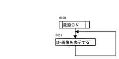
図11は電子カメラ100の動作のメインフローチャートである。まずS100で電源スイッチ17を操作すると電源がONとなり、以後S101の処理を繰り返す。S101では順次CCD55により生成される画像データをLCD21に表示することにより、いわゆるスルー画像を表示する。
【0025】
図12は電子カメラ100のシャッターボタン16を操作した場合の割込み処理のフローチャートである。まずシャッターボタン16の操作によりS200のレリーズ割込みが開始する。S201ではCCD55により撮像を行って画像データを生成し、該画像データを撮影バッファメモリ59に一時的に格納する。S202でEEPROM68に格納されたサーバアクセス情報に基づいて無線通信回路72により画像管理サーバ150に接続し、撮影バッファメモリ59に格納された画像データにEEPROM68に格納されたカメラ識別情報を添付して画像管理サーバ150に無線送信する。S203でEEPOM68に格納された撮影枚数情報に1を加え、S204でレリーズ割込み処理を終了しリターンする。
【0026】
図13は電子カメラ100がサービスショップ180に返却され、電子カメラ100がサービス端末140とケーブル接続された場合に起動する電子カメラ100の割込み処理のフローチャートである。まずサービス端末との140ケーブル接続によりS300のサービス端末割込みが開始する。S301ではサービス端末から返却処理コマンドを受信したかチェック、受信しなかった場合はS304でリターンする。返却処理コマンドを受信した場合には、S302でEEPROM68に記憶されているカメラ識別情報と撮影枚数情報をサービス端末140に送信する。S303では撮影枚数情報を0にリセットしてEEPROM68に格納し、S304でリターンする。
【0027】
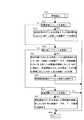
図14は電子カメラ100がサービスショップ180に返却され、電子カメラ100をサービス端末140とケーブル接続し、オペレータがサービス端末140に対して返却処理の指示を与えた場合に起動するサービス端末140の割込み処理のフローチャートである。まずオペレータの入力手段145からの指示によりS400の返却処理割込みが開始する。S401では、第2通信手段143により電子カメラ100に返却処理コマンドを送信する。S402では電子カメラ100からカメラ識別情報と撮影枚数情報を受信したかチェックし、受信できなかった場合はS407でリターンする。カメラ識別情報と撮影枚数情報を受信した場合にはS403で撮影枚数情報に応じて料金を演算手段144により計算し、表示手段145により表示する。S404では支払いが完了した否かをチェックし、支払いが行われなかった場合はS407でリターンする。支払いが完了した場合は、S405で第1通信手段142により画像管理サーバ150に返却完了コマンドとともにカメラ識別情報を送信する。S406では、画像管理サーバ150から閲覧識別情報を受信し、画像管理サーバ150へのアクセス情報と閲覧識別情報を印刷手段147により印刷し、S407でリターンする。なお画像管理サーバ150へのアクセス情報はサービス端末140に固定記憶されている。
【0028】
図15は画像管理サーバ150が外部からコマンドを受信した場合に起動する画像管理サーバ150の割込み処理のフローチャートである。まず通信手段152が外部からコマンド受信するとS500の受信割込みが開始する。S501で受信したコマンドが画像送信コマンドであるか否かチェックし、画像送信コマンドであった場合は、S502で画像送信コマンドに引き続いて受信画像メモリ154内の受信したカメラ識別情報に応じたフォルダに受信した画像データを格納し、S508でリターンする。S501で受信したコマンドが画像送信コマンドでなかった場合は、S503で受信したコマンドが返却完了コマンドであるか否かチェックし、返却完了コマンドであった場合は、管理手段153はS504で返却完了コマンドに引き続いて受信したカメラ識別情報に応じた受信画像メモリ154内のフォルダに格納した画像データを閲覧画像メモリ155内にある新しい閲覧識別情報に応じたフォルダに移動し、移動が完了すると受信画像メモリ154内のカメラ識別情報に応じたフォルダ内の画像データをクリアする。S505で画像データを移動したフォルダに対応する閲覧識別情報をサービス端末140に通信手段152により送信し、S508でリターンする。S503で受信したコマンドが返却完了コマンドでなかった場合は、S506で受信したコマンドが画像閲覧コマンドであるか否かチェックし、画像閲覧コマンドであった場合は、S507で画像閲覧コマンドに引き続いて受信した閲覧識別情報に応じた閲覧画像メモリ155内のフォルダに格納した画像データをユーザ端末160に通信手段152により送信し、S508でリターンする。S506で受信したコマンドが画像閲覧コマンドでなかった場合は、S508でリターンする。
【0029】
図16は利用者がユーザ端末160に対して画像閲覧の指示を与えた場合に起動するユーザ端末160の割込み処理のフローチャートである。まず利用者の指示によりS600の閲覧処理割込みが開始する。S601では、利用者が画像管理サーバ150へのアクセス情報と閲覧識別情報を入力手段163により入力する。S602で入力されたアクセス情報に応じてインターネット上の画像管理サーバ150に通信手段163により接続し、画像閲覧コマンドと閲覧識別情報を画像管理サーバ150に送信する。S603で画像管理サーバ150から閲覧識別情報に応じた画像データを通信手段163により受信し、画像メモリ165に格納する。S604で画像メモリ165に格納した画像データを表示手段164により表示する。
【0030】
上記実施形態(図1〜図16)の電子カメラのレンタルサービスシステムにおいては、電子カメラのレンタルサービスを受けた利用者は、電子カメラの返却時にサービスショップよりサーバアクセス情報と閲覧識別情報を受け取るのみでプリントや記憶媒体を受け取らないので、電子カメラ返却後の行動の邪魔になることはないとともに、電子カメラ返却後に撮影した画像データをすぐに確認したい場合は、前記サーバアクセス情報と閲覧識別情報に基づきユーザ端末を用いて画像データを閲覧することができる。また電子カメラのレンタルサービス提供者は電子カメラの返却時まで画像データの閲覧を禁止することにより、簡単なシステムで電子カメラの盗難を防止することができる。
(変形形態の説明)本発明は以上説明した実施形態に限定されることなく、種々の変形や変更が可能である。
【0031】
上記実施形態(図1〜図16)において、電子カメラ100側が撮影枚数を保管しているが、画像管理サーバ150に送信された画像データの数を画像管理サーバ150が管理することにより撮影枚数を管理するようにしてもよい。また電子カメラ100がスルー画像表示用のLCD21を備えているが、構図設定にはファインダ11を使用することによりLCD21を省略することもできる。このようにすれば電子カメラ100をさらに低価格で小型軽量にすることができるので、利用者にとっては気軽に使用できるとともに、サービス提供者にとってはレンタルカメラを低コストで備えられるとともに、万一盗難された場合の被害額を少なくできるというメリットがある。
【0032】
上記実施形態(図1〜図16)において、電子カメラ100が無線通信回路72を内蔵しており、撮影された画像データを該無線通信回路72により直接画像管理サーバ150に転送しているが、電子カメラ100は有線又は近距離無線(ブルーツース等)によりユーザ端末160に画像データを一旦転送し、ユーザ端末160の無線電話機能により画像データを画像管理サーバ150に転送するようにしてもよい。このようにすれば電子カメラ100に内蔵する通信回路をより低消費電力、低コスト、小型にすることができるので、サービス提供者にとってはレンタルカメラを低コストで備えられるとともに、万一盗難された場合の被害額を少なくできるというメリットがある。
【0033】
上記実施形態(図1〜図16)において、利用者は電子カメラ100を返却した際、サービスショップ180からサーバアクセス情報と閲覧識別情報を印刷したものを渡されているが、サーバアクセス情報と閲覧識別情報をサービス端末140からユーザ端末160に送信するようにしてもよい。このようにすれば、利用者が印刷情報を紛失するという危険性をなくすことができるとともに、利用者がユーザ端末160にサーバアクセス情報と閲覧識別情報を入力する手間を省くことができる。
【0034】
上記実施形態(図1〜図16)において、電子カメラ100の返却時に画像管理サーバ150は外部からの読み出しが禁止されている受信画像メモリ154から外部からの読み出しが許可されている閲覧画像メモリ155に画像データを移動することにより、電子カメラ100の貸し出し中は利用者が画像データにアクセスできないようにするとともに、電子カメラ100の返却後(料金支払い後)は利用者が自由に画像データにアクセスできるようにしているが、電子カメラ100の返却時に画像データのメモリ間の移動は行わず、画像データの属性データ(読み出し禁止/許可)のみを変更するようにしてもよい。ただしこの場合電子カメラ100のカメラ識別情報は画像管理サーバ150の管理に基づき貸し出しの度に新しいカメラ識別情報に変更する必要がある。このようにすれば、画像管理サーバ150のメモリ構成やメモリ管理を単純にすることができる。
【0035】
上記実施形態(図1〜図16)において、電子カメラ100の返却時に画像管理サーバ150は外部からの読み出しが禁止されている受信画像メモリ154から外部からの読み出しが許可されている閲覧画像メモリ155に画像データを移動しているが、電子カメラ100の返却時に画像管理サーバ150は受信画像メモリ154から利用者が指定した画像サーバに画像データを転送するようにしてもよい。この場合利用者は電子カメラ100の返却時に所望の画像サーバを指定し、指定された画像サーバのアクセス情報がサービス端末140から画像管理サーバ150に送信される。画像管理サーバ150はサービス端末140から受信したアクセス情報に基づき画像データを指定された画像サーバに転送する。このようにすれば、利用者は異なる業者のレンタルサービスを利用した場合でも特定の画像サーバに画像データを集約して利用することができるとともに、サービス提供者にとっては膨大な閲覧画像メモリを用意する必要がなくなるので、レンタルサービスシステムを低コストで構築することができる。
【0036】
上記実施形態(図1〜図16)において、画像管理サーバ150は電子カメラ100の返却時まで画像データの外部からの読み出しを禁止しているので、利用者は撮影した画像データを電子カメラ100のレンタル中に閲覧することができないが、画像管理サーバ150は電子カメラ100の返却時まで画像データの外部からの読み出しを限定した形態で読み出し許可を行っても構わない。例えば画像管理サーバ150は電子カメラ100のレンタル中にユーザ端末160から画像データの読み出し要求(閲覧要求)があった場合には、オリジナルな画像データの解像度を低下させた閲覧用画像データ(インデックス画像、サムネイル画像など)を生成し、該画像品質が低下した閲覧用画像データをユーザ端末160に送信する。この場合サービスショップ170は電子カメラ100を利用者に貸し出す際に、画像管理サーバ150へアクセスするためのサーバアクセス情報と閲覧識別情報(又はカメラ識別情報)を利用者に知らせておく。このようにすれば、利用者は電子カメラ100のレンタル中に自分が撮影した画像データをユーザ端末160の画面で閲覧することができるので、状況に応じて撮影のやり直しをすることができる。また利用者が使用するユーザ端末160は携帯性を持たせた小型な端末(携帯電話、PDA等)である場合が多く、このような小型な端末においては表示画面が比較的小さいので、画像品質が多少低下した画像データであっても、上記のような用途で画像データを閲覧するだけであれば大きな支障はない。また画像品質が低下しているので、利用者は画像データを簡易的な閲覧用途以外に本格的に利用(プリントなど)することはできない。
【0037】
また画像管理サーバ150への画像データの閲覧要求をユーザ端末160からではなく電子カメラ100から送信するようにしても構わない。例えば電子カメラ100に画像再生モードを備えておき、画像再生モードに設定された場合には、電子カメラ100はEEPROM68に記憶されたサーバアクセス情報に基づいて画像管理サーバ150に接続し、画像閲覧コマンドによりEEPROM68に記憶されたカメラ識別情報を画像管理サーバ150に送信する。画像管理サーバ150は画像閲覧コマンドを受信すると、引き続いて受信したカメラ識別情報に対応する受信画像メモリ154内のフォルダに格納された画像データを低解像度の画像データに変換して電子カメラ100に送信する。電子カメラ100は低解像度の画像データを受信すると、該画像データをLCD21に表示する。このようにすれば、サービスショップ170は電子カメラ100を利用者に貸し出す際に、画像管理サーバ150へアクセスするためのサーバアクセス情報と閲覧識別情報(又はカメラ識別情報)を利用者に知らせる必要がなくなるとともに、利用者はユーザ端末160を持っていない場合でも自分の撮影した画像データを閲覧することができる。
【0038】
【発明の効果】
以上説明したように、本発明による電子カメラ100のレンタルサービスシステムにおいては、利用者が電子カメラで撮影した画像データを外部の画像サーバの利用者がアクセスできない画像受信メモリ(バッファメモリ)に無線送信により転送して一時的に格納するとともに、電子カメラの返却時に画像受信メモリに格納した画像データを利用者がアクセス可能な画像閲覧メモリに移動し、該画像閲覧メモリに移動した画像データへのアクセス情報を利用者に報知するので、利用者は画像データをすぐに閲覧したい場合には該アクセス情報に基づいて自分の撮影した画像データにアクセスして、携帯電話等のユーザ端末の画面で画像データを閲覧することができるとともに、画像データのプリントや画像データそのものが欲しい場合は自宅に戻ってから前記アクセス情報に基づいて自宅のパソコン等に画像データをダウンロードしてCD−Rに保存したりプリントしたりすることもでき、電子カメラ返却後に画像データのプリントや画像データを保存した記憶媒体を持ち歩く必要がない。
【0039】
また本発明による電子カメラのレンタルサービスシステムにおいては、電子カメラを返却するまでは利用者が外部からアクセスできないバッファメモリに撮影された画像データを一時的に保管しておくので、電子カメラを返却しない間は利用者は不正な手段を使用しても自分が撮影した画像データにアクセスすることができないので、電子カメラの盗難を防止することができる。
【0040】
また本発明による電子カメラのレンタルサービスシステムにおいては、電子カメラはレンタル専用の構成とし、脱着可能な記憶媒体を装着する機構や画像データを保存するための内蔵メモリを備える必要がなく、場合によっては液晶等の表示デバイス等も省略することができるため、電子カメラを安価に構成でき、貸し出し時のデポジットを低価格または無料に設定できるので、レンタルサービスの利用を促進することができるとともに、一般的な使用ができない構成となっているために盗難を防止することができる。
【0041】
また本発明による電子カメラのレンタルサービスシステムにおいては、撮影した画像データを外部の画像サーバに転送するので、利用者は撮影枚数を気にすることなく撮影を楽しむことができる。
【0042】
また本発明による電子カメラのレンタルサービスシステムにおいては、基本的に利用者がサービス提供者に料金を支払って画像データへのアクセス情報を購入するという簡便なシステムになっているので、利用者とサービス提供者との間で面倒な手続きが不要で迅速なサービス提供が可能であるとともに、システム構成がシンプルなためシステム構築コストを低く押さえることができる。
【図面の簡単な説明】
【図1】電子カメラのレンタルサービスシステムの概念図である。
【図2】電子カメラのレンタルサービスシステムの構成図である。
【図3】電子カメラの外観図(正面視)である。
【図4】電子カメラの外観図(背面視)である。
【図5】電子カメラの電気構成を示すブロック図である。
【図6】EEPROMのデータの説明図である。
【図7】サービス端末の構成図である。
【図8】画像管理サーバの構成図である。
【図9】画像管理サーバのメモリ構成の説明図である。
【図10】ユーザ端末の構成図である。
【図11】電子カメラのメインフローチャートである。
【図12】電子カメラのレリーズ割込みのフローチャートである。
【図13】電子カメラのサービス端末割込みのフローチャートである。
【図14】サービス端末の返却処理割込みのフローチャートである。
【図15】画像管理サーバの受信割込みのフローチャートである。
【図16】ユーザ端末の閲覧処理割込みのフローチャートである。
【符号の説明】
10 撮影レンズ
12 ストロボ
13 測光回路
21 LCD
50 CPU
55 CCD
68 EEPROM
72 無線通信回路
100 電子カメラ
130 インターネット
140 サービス端末
150 画像管理サーバ
160 ユーザ端末[0001]
BACKGROUND OF THE INVENTION
The present invention relates to an electronic camera rental service system suitable for storing captured image data in an image server on a network for use.
[0002]
[Prior art]
Conventionally, as a rental service system using an electronic camera, a CD-R that rents an electronic camera to a user when entering a theme park or amusement park, and prints image data taken by the user when leaving or records the image data A service for passing a storage medium like this to a user is known.
[0003]
[Problems to be solved by the invention]
However, in the conventional electronic camera rental service system as described above, when the user returns the electronic camera, prints, CD-Rs, and the like increase as luggage, so that the user can easily enjoy walking and shopping thereafter. There wasn't. Also, if you rent a general-purpose electronic camera, the electronic camera lent to an inexperienced person may be stolen and used for general use. There was a need to build an anti-theft system. As a result, it became a rental service system that was difficult for users to use, and did not lead to sales success.
[0004]
SUMMARY OF THE INVENTION An object of the present invention is to provide an electronic camera rental service system that does not increase the number of luggage such as prints when the electronic camera is returned, and that can prevent the electronic camera from being stolen at low cost.
[0005]
[Means for Solving the Problems]
In order to achieve the above object, in the rental service system for an electronic camera according to the present invention, image data taken by the user with the electronic camera is stored in a received image memory (buffer memory) that cannot be accessed by the user on the external image management server. The image data stored in the received image memory when the electronic camera is returned is moved to the browsing image memory accessible by the user when the electronic camera is returned to the browsing image memory. Notify users of access information. Based on the access information, the user connects to an external image management server to access image data taken by the user, browses the image data on a user terminal such as a mobile phone, or stores the image data on a home personal computer. Download.
[0006]
DETAILED DESCRIPTION OF THE INVENTION
Hereinafter, embodiments of the present invention will be described with reference to the drawings. FIG. 1 is a conceptual diagram of an electronic camera rental service system according to the present invention. First, a user rents an
[0007]
The user returns the
[0008]
The user accesses the
[0009]
FIG. 2 is a block diagram of an electronic camera rental service system according to the present invention. The
[0010]
3 and 4 are external views (front view and back view) of an embodiment of the
[0011]
As shown in FIG. 4, an eyepiece of the finder 11 and an LCD (screen) 21 having a substantially rectangular screen for displaying text and images are arranged on the back of the
[0012]
FIG. 5 is a block diagram showing an example of the internal electrical configuration of the
[0013]
The
[0014]
The photographing control circuit 60 performs focusing of the photographing
[0015]
The analog processing unit 57 samples the image signal photoelectrically converted by the CCD 55 at a predetermined timing, and amplifies the sampled signal to a predetermined level. The A / D conversion circuit 58 (analog / digital conversion circuit) digitizes the image signal sampled by the analog processing unit 57 to convert it into digital data, and the photographing
[0016]
The photographing control circuit 60 repeats the above-described operation, and the
[0017]
When the shooting control circuit 60 receives a shooting instruction from the
[0018]
FIG. 6 is a diagram showing a configuration of information stored in the EEPROM 68. Server identification information for identifying an individual of the
[0019]
FIG. 7 is a diagram showing a configuration of the
[0020]
FIG. 8 is a diagram showing the configuration of the
[0021]
FIG. 9 is a diagram illustrating a memory configuration of the
[0022]
The browsing image memory is further divided into folders corresponding to the browsing identification information. Here, the browsing identification information is identification information attached to identify a group of image data taken during one rental period of the
[0023]
FIG. 10 is a diagram showing the configuration of the
[0024]
FIG. 11 is a main flowchart of the operation of the
[0025]
FIG. 12 is a flowchart of interrupt processing when the shutter button 16 of the
[0026]
FIG. 13 is a flowchart of interrupt processing of the
[0027]
FIG. 14 shows an interrupt of the
[0028]
FIG. 15 is a flowchart of interrupt processing of the
[0029]
FIG. 16 is a flowchart of an interrupt process of the
[0030]
In the electronic camera rental service system of the above embodiment (FIGS. 1 to 16), the user who has received the electronic camera rental service only receives server access information and browsing identification information from the service shop when the electronic camera is returned. If you want to check the image data taken immediately after returning the electronic camera, you can use the server access information and the browsing identification information. Based on this, image data can be browsed using the user terminal. In addition, the electronic camera rental service provider can prevent the electronic camera from being stolen with a simple system by prohibiting browsing of the image data until the electronic camera is returned.
(Description of Modifications) The present invention is not limited to the embodiment described above, and various modifications and changes can be made.
[0031]
In the above embodiment (FIGS. 1 to 16), the
[0032]
In the above embodiment (FIGS. 1 to 16), the
[0033]
In the above embodiment (FIGS. 1 to 16), when the user returns the
[0034]
In the above embodiment (FIGS. 1 to 16), when the
[0035]
In the above embodiment (FIGS. 1 to 16), when the
[0036]
In the above embodiment (FIGS. 1 to 16), the
[0037]
The image data browsing request to the
[0038]
【The invention's effect】
As described above, in the rental service system of the
[0039]
In addition, in the electronic camera rental service system according to the present invention, the captured image data is temporarily stored in a buffer memory that the user cannot access from the outside until the electronic camera is returned, so the electronic camera is not returned. In the meantime, since the user cannot access the image data taken by himself / herself even by using unauthorized means, the theft of the electronic camera can be prevented.
[0040]
In the rental service system for an electronic camera according to the present invention, the electronic camera has a rental-only configuration, and does not need a mechanism for mounting a removable storage medium or a built-in memory for storing image data. Since display devices such as liquid crystal can be omitted, the electronic camera can be configured at low cost, and the rental deposit can be set at a low price or free of charge. It is possible to prevent theft because it is configured so that it cannot be used.
[0041]
In the electronic camera rental service system according to the present invention, the captured image data is transferred to an external image server, so that the user can enjoy shooting without worrying about the number of shots.
[0042]
In the electronic camera rental service system according to the present invention, the user basically pays a fee to the service provider and purchases access information to the image data. Troublesome procedures with the provider are not required and prompt service provision is possible, and the system construction cost is low because the system configuration is simple.
[Brief description of the drawings]
FIG. 1 is a conceptual diagram of an electronic camera rental service system.
FIG. 2 is a configuration diagram of an electronic camera rental service system.
FIG. 3 is an external view (front view) of the electronic camera.
FIG. 4 is an external view (back view) of the electronic camera.
FIG. 5 is a block diagram showing an electrical configuration of the electronic camera.
FIG. 6 is an explanatory diagram of EEPROM data.
FIG. 7 is a configuration diagram of a service terminal.
FIG. 8 is a configuration diagram of an image management server.
FIG. 9 is an explanatory diagram of a memory configuration of the image management server.
FIG. 10 is a configuration diagram of a user terminal.
FIG. 11 is a main flowchart of the electronic camera.
FIG. 12 is a flowchart of a release interrupt of the electronic camera.
FIG. 13 is a flowchart of service terminal interruption of the electronic camera.
FIG. 14 is a flowchart of service terminal return process interruption;
FIG. 15 is a flowchart of a reception interrupt of the image management server.
FIG. 16 is a flowchart of user terminal browsing processing interruption;
[Explanation of symbols]
10 Shooting lens
12 Strobe
13 Photometric circuit
21 LCD
50 CPU
55 CCD
68 EEPROM
72 Wireless communication circuit
100 electronic camera
130 Internet
140 Service terminal
150 Image management server
160 User terminal
Claims (6)
Translated fromJapanese前記電子カメラから送信された画像データを受信する通信機能と前記受信した画像データを保管する画像保管機能を備える画像サーバと、
前記電子カメラのレンタル情報を前記画像サーバに送信する通信機能を備えるサービス端末と
からなる電子カメラのレンタルサービスシステムであって、
前記電子カメラは撮影した画像データを内部に記憶せずに前記画像サーバに全て送信するとともに、前記画像データを前記画像サーバに送信する際に、前記画像データに個々の電子カメラを個体識別するためのカメラ識別情報を付加して前記画像サーバに送信し、
前記画像サーバは受信した画像データに付加されたカメラ識別情報に応じ、同一のカメラ識別情報が付加された画像データのグループを異なるカメラ識別情報が付加された画像データのグループと区別して保管し、
前記サービス端末が前記画像サーバに送信する前記レンタル情報は、前記電子カメラが返却されたことを表す返却完了情報と、返却された電子カメラに対応するカメラ識別情報とからなり、
前記画像サーバは前記サービス端末から前記カメラ識別情報と前記返却完了情報を受信する以前は、前記カメラ識別情報に応じて保管された画像データのグループに対し外部からの読み出しを制限することを特徴とする電子カメラのレンタルサービスシステム。An electronic camera having an imaging function for photographing a subject and generating image data and a communication function for transmitting the image data to an external image server;
An image server having a communication function for receiving image data transmitted from the electronic camera and an image storage function for storing the received image data;
An electronic camera rental service system comprising a service terminal having a communication function for transmitting rental information of the electronic camera to the image server,
The electronic camera transmits all of the captured image data to the image server without storing them internally, and when the image data is transmitted to the image server, to individually identify each electronic camera in the image data The camera identification information is added and sent to the image server,
According to the camera identification information added to the received image data, the image server stores a group of image data to which the same camera identification information is added separately from a group of image data to which different camera identification information is added,
The rental information transmitted to the image server by the service terminal includes return completion information indicating that the electronic camera has been returned, and camera identification information corresponding to the returned electronic camera.
Before the image server receives the camera identification information and the return completion information from the service terminal, the image server limits reading from the outside to a group of image data stored in accordance with the camera identification information. Electronic camera rental service system.
Priority Applications (1)
| Application Number | Priority Date | Filing Date | Title |
|---|---|---|---|
| JP2002104699AJP3948328B2 (en) | 2002-04-08 | 2002-04-08 | Electronic camera rental service system |
Applications Claiming Priority (1)
| Application Number | Priority Date | Filing Date | Title |
|---|---|---|---|
| JP2002104699AJP3948328B2 (en) | 2002-04-08 | 2002-04-08 | Electronic camera rental service system |
Publications (2)
| Publication Number | Publication Date |
|---|---|
| JP2003304478A JP2003304478A (en) | 2003-10-24 |
| JP3948328B2true JP3948328B2 (en) | 2007-07-25 |
Family
ID=29389784
Family Applications (1)
| Application Number | Title | Priority Date | Filing Date |
|---|---|---|---|
| JP2002104699AExpired - Fee RelatedJP3948328B2 (en) | 2002-04-08 | 2002-04-08 | Electronic camera rental service system |
Country Status (1)
| Country | Link |
|---|---|
| JP (1) | JP3948328B2 (en) |
Families Citing this family (6)
| Publication number | Priority date | Publication date | Assignee | Title |
|---|---|---|---|---|
| WO2005048585A1 (en)* | 2003-11-14 | 2005-05-26 | Bawden Holdings Limited | Method of distributing a recyclable video camera |
| JP4663491B2 (en)* | 2005-11-16 | 2011-04-06 | オリンパスイメージング株式会社 | Imaging device |
| JP2008017231A (en)* | 2006-07-06 | 2008-01-24 | Ricoh Co Ltd | Communication device |
| JP4714106B2 (en)* | 2006-08-02 | 2011-06-29 | シャープ株式会社 | Image storage system and image storage method |
| JP5975020B2 (en)* | 2012-12-21 | 2016-08-23 | キヤノンマーケティングジャパン株式会社 | Information processing apparatus, information processing system, control method thereof, and program |
| JP6377672B2 (en)* | 2016-02-23 | 2018-08-22 | 株式会社 ミックウェア | system |
- 2002
- 2002-04-08JPJP2002104699Apatent/JP3948328B2/ennot_activeExpired - Fee Related
Also Published As
| Publication number | Publication date |
|---|---|
| JP2003304478A (en) | 2003-10-24 |
Similar Documents
| Publication | Publication Date | Title |
|---|---|---|
| US7764308B2 (en) | Image transmission system, image relay apparatus, and electronic image device | |
| JP4239497B2 (en) | Image transmission system, image relay device, and electronic image equipment | |
| JP3395898B2 (en) | Image data processing system | |
| US7042496B2 (en) | Photo service system and digital camera | |
| JP2003179840A (en) | Electronic camera, electronic device, image transmission system, and image transmission method | |
| US7092010B2 (en) | Image photographing system | |
| JP2011170194A (en) | Photographing device and photographing control method | |
| KR100774053B1 (en) | Image pickup apparatus, image recording apparatus, computer readable recording medium recording a program for the image pickup apparatus, computer readable recording medium recording a program for the image recording apparatus, an image pickup method and an image recording method | |
| JP3948328B2 (en) | Electronic camera rental service system | |
| JP2001211364A (en) | Digital camera | |
| JP2003345701A (en) | Image transmission system and image relay device | |
| JP4569032B2 (en) | Electronic equipment and electronic equipment system | |
| JP2001111884A (en) | Electronic camera with wireless communication means | |
| JP2009111827A (en) | Imaging device and image file providing system | |
| JP4499275B2 (en) | Electronic camera system and electronic camera | |
| JP4323942B2 (en) | Image transmitting apparatus, image receiving apparatus, image transmitting method, image receiving method, and image communication system | |
| JP4126717B2 (en) | Recording device, communication device, recording system and method thereof | |
| JP4851047B2 (en) | Image transmission system and image relay apparatus | |
| JP2003316892A (en) | Ic card, photographic device and communication system | |
| JP2003348516A (en) | Image transmission system, image repeating apparatus and electronic image equipment | |
| JP2003078850A (en) | Image data storage system, imaging device, server system and communication card | |
| JP2004274245A (en) | Digital camera and its image management system | |
| JP2000341618A (en) | Image data processing system | |
| JP2005020398A (en) | Camera system and digital camera | |
| JP2004336574A (en) | Network customizing service providing method and system for the service |
Legal Events
| Date | Code | Title | Description |
|---|---|---|---|
| A621 | Written request for application examination | Free format text:JAPANESE INTERMEDIATE CODE: A621 Effective date:20050329 | |
| TRDD | Decision of grant or rejection written | ||
| A01 | Written decision to grant a patent or to grant a registration (utility model) | Free format text:JAPANESE INTERMEDIATE CODE: A01 Effective date:20070327 | |
| A61 | First payment of annual fees (during grant procedure) | Free format text:JAPANESE INTERMEDIATE CODE: A61 Effective date:20070409 | |
| R150 | Certificate of patent or registration of utility model | Ref document number:3948328 Country of ref document:JP Free format text:JAPANESE INTERMEDIATE CODE: R150 Free format text:JAPANESE INTERMEDIATE CODE: R150 | |
| FPAY | Renewal fee payment (event date is renewal date of database) | Free format text:PAYMENT UNTIL: 20100427 Year of fee payment:3 | |
| FPAY | Renewal fee payment (event date is renewal date of database) | Free format text:PAYMENT UNTIL: 20130427 Year of fee payment:6 | |
| S531 | Written request for registration of change of domicile | Free format text:JAPANESE INTERMEDIATE CODE: R313531 | |
| FPAY | Renewal fee payment (event date is renewal date of database) | Free format text:PAYMENT UNTIL: 20130427 Year of fee payment:6 | |
| R350 | Written notification of registration of transfer | Free format text:JAPANESE INTERMEDIATE CODE: R350 | |
| FPAY | Renewal fee payment (event date is renewal date of database) | Free format text:PAYMENT UNTIL: 20130427 Year of fee payment:6 | |
| FPAY | Renewal fee payment (event date is renewal date of database) | Free format text:PAYMENT UNTIL: 20140427 Year of fee payment:7 | |
| R250 | Receipt of annual fees | Free format text:JAPANESE INTERMEDIATE CODE: R250 | |
| R250 | Receipt of annual fees | Free format text:JAPANESE INTERMEDIATE CODE: R250 | |
| R250 | Receipt of annual fees | Free format text:JAPANESE INTERMEDIATE CODE: R250 | |
| R250 | Receipt of annual fees | Free format text:JAPANESE INTERMEDIATE CODE: R250 | |
| R250 | Receipt of annual fees | Free format text:JAPANESE INTERMEDIATE CODE: R250 | |
| R250 | Receipt of annual fees | Free format text:JAPANESE INTERMEDIATE CODE: R250 | |
| R250 | Receipt of annual fees | Free format text:JAPANESE INTERMEDIATE CODE: R250 | |
| LAPS | Cancellation because of no payment of annual fees |