JP3947577B2 - Treatment system - Google Patents
Treatment systemDownload PDFInfo
- Publication number
- JP3947577B2 JP3947577B2JP19548295AJP19548295AJP3947577B2JP 3947577 B2JP3947577 B2JP 3947577B2JP 19548295 AJP19548295 AJP 19548295AJP 19548295 AJP19548295 AJP 19548295AJP 3947577 B2JP3947577 B2JP 3947577B2
- Authority
- JP
- Japan
- Prior art keywords
- frequency
- cable
- coaxial
- applicator
- oscillator
- Prior art date
- Legal status (The legal status is an assumption and is not a legal conclusion. Google has not performed a legal analysis and makes no representation as to the accuracy of the status listed.)
- Expired - Fee Related
Links
Images


Landscapes
- Surgical Instruments (AREA)
Description
Translated fromJapanese【0001】
【発明の属する技術分野】
本発明は、各々異なる周波数を発振する2つ以上の周波数発振器から与えられる電力をアプリケータによって生体に供給することにより外科的処置を行う処置システムに関する。
【0002】
【従来の技術】
USP第4,188,927号明細書において、生体に異なる周波数の高周波を同時に供給しようとするシステムが開示されている。このシステムでは生体に流れる高周波電流の周波数成分に異なる周波数があるという、AM変調された高周波が流れるものであり、これは別個に異なる周波数が流れるというものとは異なる。また、どの周波数についても一対の同じ電極を用いて生体にAM変調された高周波電流を流そうとしている。
【0003】
この方式ではAM変調された高周波電流を流そうとしているから高い方の周波数についての成分の伝送にはどうしても現実的に技術的限界がある。数十MHzまでの周波数であれば何とか、この方式でもそれなりに生体へ有効に供給可能であるが、それ以上の周波数の高周波については取り扱うことができなかった。しかし、生体の凝固等にはもっと高い周波数の高周波電流が効果的であるが、この方式ではそのような高い周波数の高周波電流を有効に取り扱うことができないことになってしまう。
【0004】
外科臨床ハンドブック「内視鏡下手術の最前線」('94.6.10中山書店発行)においては前述した問題点を解決するために切換え手段によって異なる周波数の高周波電流を選択的に同一のアプリケータから出力させるようになっており、これは異なる周波数の高周波電流を同時に流すことは不可能なものであった。
【0005】
【発明が解決しようとする課題】
従来より、例えば高周波メスは、切開能力には優れているが、凝固能力はマイクロ波メスの方が優れている等の、周波数とその周波数での電力の特徴があることは解っていた。それぞれの優れている能力を同一のアプリケータにて使用できれば最も優れたシステムとして使用できる。
【0006】
前記内容を具現化し、単に切換スイッチを用いて高周波とマイクロ波を切換えることで共通のアプリケータに高周波メスとマイクロ波メスの能力を与えているものや、磁気的にアプリケータを複数の高周波発振器に接続する方法は既に研究発表や特許として公表されているが、このシステムも、複数の高周波を確実に同時に出すことはできない。特に、同軸出力の高周波と2線出力の高周波を同時に出すものはまだ手付かずの状態である。
【0007】
よって、従来の高周波メスのブレンドモード(切開+凝固)に相当するもので、複数の周波数の高周波をブレンドしたものは存在していない。
【0008】
本発明は、前記課題に着目してなされたもので、その目的とするところは、同一のアプリケータで2つ以上の異なる能力を持つ周波数の電力を用いて生体に対するそれぞれの能力を発揮させることができる処置システムを提供することにある。
【0009】
【課題を解決するための手段】
本発明は、同軸出力の高周波であるマイクロ波を発振する第1の高周波発振器と、前記第1の高周波発振器が出力する同軸出力の高周波電力を伝送する同軸ケーブルと、2線出力の高周波を出力する第2の高周波発振器と、前記第2の高周波発振器が出力する2線出力の高周波電力を伝送するための2本のケーブルと、前記同軸ケーブルの先端から露出するように突き出した前記同軸ケーブルの内部導体の先端部と前記同軸ケーブルの外部導体の先端により前記同軸出力の高周波出力用アンテナ部を形成し、前記先端部により前記2線出力の高周波出力のアクティブ電極を形成し、前記同軸出力の高周波電力と前記2線出力の高周波電力の両方を生体に同時に与える外科的処置を行うアプリケータと、前記第1の高周波発振器に前記同軸ケーブルを電気的に接続すると共に、前記2線出力の高周波電力を伝送する2本のケーブルにおける一方のケーブルを前記同軸ケーブルの内部導体または外部導体に電気的に接続し、前記2本のケーブルにおける他方のケーブルを患者の体表面に装着される高周波電流回収用プレートに対し電気的に接続し、前記第1の高周波発振器が出力する高周波電力と前記第2の高周波発振器が出力する高周波電力との両方を、同時に前記同軸ケーブルを通じて前記アプリケータに供給するようにした供給手段と、を備えたことを特徴とする異周波数同時処置システムである。
これによって、同一のアプリケータにて、複数の処置能力を有することになる。さらに、複数の出力を同時に与えて処置するため、それぞれの能力を合わせ持ち、同一のアプリケータにて切開と凝固・止血等を同時に行うことができる。
【0010】
【発明の実施の形態】
<第1の実施形態>
図1ないし図3を参照して第1実施形態を説明する。図1はその実施形態の概略的なシステム構成を示し、図2はミキサーの重要な部分を示し、図3はアプリケータの先端部分を示す。
【0011】
このシステムにおいての高周波電力源としては同軸出力高周波発振器1と2線出力高周波発振器2の2つの発振器を備える。そして、同軸出力高周波発振器1はマイクロ波発振器等から構成されており、これには同軸出力高周波用フットスイッチ3と同軸ケーブルである中継同軸ケーブル4が接続されている。一方、2線出力高周波発振器2には2線出力高周波用フットスイッチ5と、各出力ラインである高周波プレート・ケーブル6と中継アクティブ・ケーブル7が接続されている。高周波プレート・ケーブル6には高周波患者プレート8が接続されており、この高周波患者プレート8は患者9の外表面に対して装着されるようになっている。
【0012】
中継同軸ケーブル4と中継アクティブ・ケーブル7は後述するミキサー11の入力端に接続され、ミキサー11の出力端には同軸ケーブルであるアプリケータ・ケーブル12が接続される。アプリケータ・ケーブル12の他端にはコネクタを介してアプリケータ13が接続されている。
【0013】
前記ミキサー11は2線出力の高周波と同軸出力の高周波をアプリケータ出力系に合流させるものであり、このミキシング部分の構造は図2で示すように構成されている。すなわち、前記中継同軸ケーブル4に対してコネクタを介して接続する同軸ケーブルである同軸出力発振器側ケーブル15と、前記アプリケータ・ケーブル12に対してコネクタを介して接続する同軸ケーブルであるアプリケータ側ケーブル16が設けられており、この両ケーブル15,16はフランジ17を付設した同軸コネクタ18を介して同軸的に接続されている。
【0014】
このフランジ付同軸コネクタ18はフランジ17の部分およびこれと一体の外部接触可能部分19を導電金属にて構成されており、この導電金属部分は同軸出力発振器側ケーブル15やアプリケータ側ケーブル16の外部導体と電気的に導通している。そして、このフランジ付同軸コネクタ18のフランジ17またはその他の外部接触可能部分19には、前記中継アクティブ・ケーブル7(2線出力の高周波電力を伝送するための2本の伝送ケーブルのうちの1本のライン)にコネクタを介して接続する2線出力発振器側ケーブル21が電気的に接続されている。結局のところ2線出力発振器側ケーブル21は同軸出力発振器側ケーブル15やアプリケータ側ケーブル16の外部導体と電気的に接続されることになる。
【0015】
以上により異なる周波数の複数の電力の1つ以上を選択してこの電力を前記アプリケータ13を用いて生体にそれぞれ供給する合流手段を構成している。
【0016】
また、ミキサー11内において、同軸出力発振器側ケーブル15の途中には、円筒状に形成した高周波電流の遮断用フェライトコア22が被嵌して装着されている。この装着方法は同軸出力発振器側ケーブル15を円筒状のフェライトコア22の中空部分に通す方法で行う。
【0017】
また、図3で示すように、アプリケータ13はアプリケータ・ケーブル12の先端部分でその同軸ケーブルの内部導体25を露出して突き出し、この突出部分を先端処置部14として形成している。この先端処置部14を患者9の治療部位に接触させることにより高周波による外科的処置を行う。
前記同軸ケーブルは内部導体25と外部導体26の間に絶縁体27を介在しており、外部導体26は外皮28によって覆われている。
【0018】
次に、このシステムの実際上の使用法とその際の作用について説明する。まず、使用にあたり、図1に示すように各部分を接続して準備する。アプリケータ13を体腔内に導入し、そのアプリケータ13の先端処置部14を患者9の治療部位に接触させる。ここで、アプリケータ13の先端処置部14は2線出力高周波メスのアクティブ電極の役目と、同軸出力高周波メスのアンテナ部の役目の両方を果たすことになる。
【0019】
そこで、高周波電流を患部に流して切開・凝固を行う場合には、2線出力高周波用フットスイッチ5を踏むことにより2線出力高周波発振器2の発振が開始され、その2線出力高周波用フットスイッチ5が踏まれている間、高周波電流が供給される。この際に高周波電流が流れるルートは、
2線出力高周波発振器2->中継アクティブ・ケーブル7->ミキサー11(2線出力発振器側ケーブル21->フランジ付同軸コネクタ18のフランジ17->アプリケータ側ケーブル16の外部導体->アプリケータ・ケーブル12の外部導体)->アプリケータ・ケーブル12の内部導体->アプリケータ13の先端処置部14->患者9->高周波患者プレート8->高周波プレート・ケーブル6->2線出力高周波発振器2の順となる。
【0020】
アプリケータ・ケーブル12の外部導体からその内部導体へ高周波電流が流れるのはその外部導体と内部導体との間の静電結合によるものであり、従って、直流レベルでの接触はない。
【0021】
また、同軸出力高周波電力を患部に放射して凝固を行う場合には、同軸出力高周波用フットスイッチ3を踏むことにより行う。これによると、同軸出力高周波発振器1の発振が開始され、その同軸出力高周波用フットスイッチ3が踏まれている間、同軸出力高周波電力がアプリケータ13の先端処置部14より放射される。この同軸出力高周波電力は同軸出力高周波発振器1よりアプリケータ13の先端処置部14まで同軸モードで伝送される。この際の伝送ルートは、
同軸出力高周波発振器1->中継同軸ケーブル4->ミサキー11(同軸出力発振器側ケーブル15->フランジ付同軸コネクタ18->アプリケータ側ケーブル16)->アプリケータ・ケーブル12->アプリケータ13の先端処置部14->患者9の順となる。
【0022】
また、2線出力高周波電力と同軸出力高周波を同時に患者9の患部に作用させる場合には、同軸出力高周波用フットスイッチ3と2線出力高周波用フットスイッチ5とを同時期に踏むことによって可能となる。各電力を前記アプリケータ13を用いて生体にそれぞれ供給し、異なる周波数の高周波による外科的治療を同時に行うことができる。
【0023】
なお、高周波電流がミキサー11内の2線出力発振器側ケーブル21から同軸出力発振器側ケーブル15の方へ流れて、同軸出力高周波発振器1からアース経由で2線出力高周波発振器2に流れることを防止している。同軸出力高周波発振器1や2線出力高周波発振器2の絶縁状況をより強固にすると共に、図2に示すようにフェライトコア22を同軸出力発振器側ケーブル15に通すことで対策できる。このフェライトコア22は、同軸出力発振器側ケーブル15を単なる導線として用いている高周波に対しては、ケーブルから発生している電磁界がそのケーブルの外に位置しているので、ハイ・インピーダンスとしての効果を示し、電流をカットすることになる。しかし、同軸ケーブルとして用いている同軸出力高周波に対しては、電磁界がケーブル内部の同軸モードの導波路内でしか発生していないので、フェライトコア22の影響はなく、同軸出力高周波を減衰させることはない。なお、フェライトコア22については、必ず必要な要素ではなく、あると良いといったものであり、これ無しでもミキサー11の役目は果たすことができる。
【0024】
以上の構成によれば、同一のアプリケータ13を2線出力高周波メスと同軸出力高周波メスの両方に使用することが可能となる。さらに、2線出力高周波メスと同軸出力高周波メスの効果を同時に発生させることが可能となる。例えば、数百キロHzの2線出力高周波メスは特に切開能力に優れ、ギガHz帯の同軸出力高周波メスは凝固能力に優れていると言われている。よって、この2つの能力を同時に出力することが可能となり、よりスピーディでかつ安全で出血の少ない高周波メスとしての使用が可能となる。
【0025】
その他にも2線出力高周波メスにより切開・止血を行い、同軸出力高周波メスによって患部(癌細胞等)を凝固・死滅させる等、いろいろな用途のバリエーションがあるが、2線出力高周波メスと同軸出力高周波メスの両方を使用することによる利点が発生する使用法全てがこの実施形態の対象となろう。特に、同時に2線出力高周波メスと同軸出力高周波メスを発生させたい使用法がよりマッチした使用法である。
【0026】
また、このシステムであれば、ユーザーが既に所有している2線出力高周波発振器や同軸出力高周波発振器をそのまま用いて、新たにミキサーと接続ケーブルの一部とアプリケータのみを購入すればよく、非常に安価にシステムを構築することができる。
【0027】
<第2の実施形態>
図4を参照して第2実施形態を説明する。これは前述した第1実施形態と異なるミキシング部の同軸コネクタ部分31について示している。すなわち、これはフランジ付の同軸コネクタを付加的に設けるのではなく、2線出力発振器側ケーブル21をアプリケータ側ケーブル16の外部導体26に接続させるに当たり、そのアプリケータ側ケーブル16に被覆無しケーブル部32を形成し、その剥き出しになった外部導体26に対して2線出力発振器側ケーブル21を半田付け等の方法で接続させたものである。
【0028】
この第2実施形態のシステムの使用方法については前述した第1実施形態のものと同じである。
この実施形態によれば、前述した第1実施形態と効果は同じである上に、特別のフランジ付同軸コネクタを付設することが不要となり、部品点数を減らすことができる。また、被覆無しケーブル部32を小さくすることによって、2線出力高周波発振器のアクティブ電極ラインが剥き出しになった部分を小さくすることができ、ミキサー11のケースを開けた状態でサービスマン等が動作させる場合の安全性が向上する。
【0029】
<第3の実施形態>
図5を参照して第3実施形態を説明する。これは、前述した第1実施形態と異なるミキサー部分の同軸コネクタ部について示している。すなわち、2線出力高周波と同軸出力高周波をミキシングする部分に分岐同軸コネクタ35を使用するものである。そして、同軸出力発振器側ケーブル15とアプリケータ側ケーブル16は同軸コネクタを介して分岐同軸コネクタ35に接続し、2線出力発振器側ケーブル21は分岐同軸コネクタ35の残った端子部の中心導体に接続するようにしたものである。その他の構成は前述した実施形態と同じである。
【0030】
この使用方法は第1の実施形態と同じであるが、2線出力の高周波電流の流れるルートが異なる。2線出力発振器側ケーブル21から分岐同軸コネクタ35の内部導体を介して直接にアプリケータ側ケーブル16の内部導体に接続されており、アプリケータ・ケーブル12の外部導体と内部導体の静電容量を使用せずに高周波電流はアプリケータ13の先端処置部14へ流れる。
【0031】
この実施形態の場合、第1の実施形態の効果と共に、アプリケータ・ケーブル12の静電容量を使用せずに、いわゆるミキシングを行っているので、ミキシング部分とアプリケータ13の先端との間の同軸ケーブル長を極端に短くすることが可能となる。すなわち、アプリケータ・ケーブル12が極端に短い、または無い実施形態も可能となる。また、アプリケータ13にミキサー11が組み込まれている方式のものにも適用可能となる。
【0032】
<第4の実施形態>
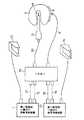
図6および図7を参照して第4の実施形態を説明する。図6はセレクト・ボタンの例を示し、図7はそのシステム構成の説明図である。
この実施形態のシステムでの電力源としては同軸出力高周波発振器1と2線出力高周波発振器2の2つの発振器を備えている。同軸出力高周波発振器1には、中継同軸ケーブル4と同軸出力発振器用フットスイッチ・ケーブル41とが接続されている。また、2線出力高周波発振器2には、2線出力発振器用フットスイッチ・ケーブル42と中継プレート・ケーブル43と中継アクティブ・ケーブル44が接続されている。同軸出力高周波発振器1及び2線出力高周波発振器2に接続された前記ケーブル類は全部ミキサー45に接続される。このミキサー45は前記ミキサー11とはその使用形式が異なっている。
【0033】
中継同軸ケーブル4と中継アクティブ・ケーブル44を通して供給されるそれぞれの高周波はミキサー45に入力され、その内部で前述したようにしてミキシングされる。このミキシングされた出力はミキサー45の出力端に接続される同軸ケーブルであるアプリケータ・ケーブル12へ出力される。
【0034】
また、ミキサー45には両用1連フットスイッチ46が接続されており、セレクト・ボタン操作部47にて選択されたモードに従った信号処理を経て、ミキサー45から同軸出力発振器用フットスイッチ・ケーブル41と2線出力発振器用フットスイッチ・ケーブル42を介して同軸出力高周波発振器1と2線出力高周波発振器2に発振のON/OFF信号が出力される。また、中継プレート・ケーブル43はミキサー45に対して同様に接続される高周波プレート・ケーブル6にミキサー45内で接続される。
【0035】
アプリケータ・ケーブル12の他端にはアプリケータ13が接続され、アプリケータ13の先端処置部14を患者9の治療部位に接触させる。高周波プレート・ケーブル6には高周波患者プレート8が接続されており、その高周波患者プレート8は患者9に装着されるようになっている。
【0036】
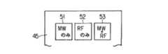
また、前記セレクト・ボタン47の1例を図6に示す。ボタンの種類としては、例えば同軸出力の高周波がマイクロ波であるとすると、マイクロ波のみのボタン51、高周波のみのボタン52、マイクロ波+高周波のボタン53の3種となる。
【0037】
前記ミキサー45の内部では、第1〜3実施形態で開示されている同軸出力高周波と2線出力高周波をそれぞれ供給するためのミキシング機構が存在する。ミキサー45のパネル上に設けられているセレクト・ボタン操作部47にて選択されたモードに従って、両用1連フットスイッチ46からのON信号を、マイクロ波のみのモード時は同軸出力高周波発振器1のみに、高周波のみのモード時には2線出力高周波発振器2のみに、マイクロ波+高周波のモード時には両発振器1,2に動作信号を送るような回路が内蔵されている。もっとも、ミキシング機構については第1実施形態の機構のものに限定されるものではない。
【0038】
次に、このシステムの実際の使用法を、マイクロ波と高周波の組み合わせた例にして示す。まず、図7に示すように各部分をそれぞれ接続する。そして、アプリケータ13を体腔内に導入し、そのアプリケータ13の先端処置部14を患者9の治療部位に接触させる。このアプリケータ13の先端処置部14は2線出力高周波メスのアクティブ電極の役目と、同軸出力高周波のアンテナ部の役目の両方を果たす。
【0039】
まず、2線出力高周波電流を患部に流して切開・凝固を行う時には、セレクト・ボタン操作部47で高周波のみのモードを選択する。そして、両用1連フットスイッチ46を踏むことにより2線出力高周波発振器2の発振が開始され、両用1連フットスイッチ46が踏まれている間、高周波電流が流れる。この流れるルートは、ミキサー45の内部のミキシング機構を第1の実施形態と同じとすると、2線出力高周波発振器2->中継アクティブ・ケーブル44->ミキサー45->アプリケータ・ケーブル12の外部導体->アプリケータ・ケーブル12の内部導体->アプリケータ13の先端処置部14->患者9->高周波患者プレート8->高周波プレート・ケーブル6->ミキサー45->中継プレート・ケーブル43->2線出力高周波発振器2となる。
【0040】
アプリケータ・ケーブル12の外部導体から内部導体に2線出力高周波電流が流れるのはその外部導体と内部導体の間の静電結合によるものであり、直流レベルでの接触は無い。
【0041】
また、同軸出力高周波を患部に放射して凝固を行う場合には、セレクト・ボタン操作部47でマイクロ波のみのモードを選択する。そして、両用1連フットスイッチ46を踏むことにより同軸出力高周波発振器1の発振が開始され、両用1連フットスイッチ46が踏まれている間、同軸出力高周波電力がアプリケータ13の先端処置部14より放射される。この同軸出力高周波電力は同軸出力高周波発振器1よりアプリケータ13の先端処置部14まで同軸モードで伝送される。この際の伝送ルートは、同軸出力高周波発振器1->中継同軸ケーブル4->ミサキー45->アプリケータ・ケーブル12->アプリケータ13の先端処置部14->患者9となる。
【0042】
この2種類の高周波を同時に患者9の患部に作用させるには、セレクト・ボタン操作部47でマイクロ波+高周波のモードを選択し、両用1連フットスイッチ46を踏むことによって可能となる。
【0043】
この実施形態によれば、前記第1実施形態の効果に加えて、以下のような2つの効果も奏する。
その1つは同軸出力高周波発振器1と2線出力高周波発振器2からのケーブルをミキサー45に接続した状態で普段からシステムとして設置しておけば、実際にユーザーが使用する時にはフットスイッチ46、アプリケータ・ケーブル12、高周波プレートケーブル6のみをミキサー45へ接続すれば良い。これによって、機器の配線が非常にすっきりとすることである。
【0044】
もう1つはセレクト・ボタンでの出力モード設定機能により、2線出力高周波と同軸出力高周波の出力ON/OFF制御を1連のフットスイッチ46で行うことができ、各別にフットスイッチを設ける必要がないから、フットスイッチが沢山あることによる紛らわしさを無くすことができる。
【0045】
なお、この実施形態ではミキサー45による同軸出力高周波発振器1と2線出力高周波発振器2の制御機能をON/OFFのみに止めているが、さらにミキサーに同軸出力高周波出力制御つまみや2線出力高周波出力制御つまみ、高周波電流モード切換ボタン(切開,凝固,ブレンド等)を設け、それらのつまみ類でユーザーは設定を行い、ミキサーから信号ケーブルを介して同軸出力高周波発振器や2線出力高周波発振器の遠隔操作を行うことで、第4実施形態の効果をさらに大きくできる。また、同軸出力高周波発振器や2線出力高周波発振器は全く表に見せること無くシステムを使うことができる形態も、この実施形態の延長として考えることができる。
【0046】
<第5の実施形態>
図8を参照して第5実施形態を説明する。図8はそのシステム構成を示している。この実施形態のシステムでの電力源としても同軸出力高周波発振器1と2線出力高周波発振器2の2つの発振器を備えるが、その2線出力高周波発振器2は前述したようないわゆるミキサー部を内蔵したものである。
【0047】
同軸出力高周波発振器1には、同軸ケーブルである中継同軸ケーブル4と、同軸出力発振器用フットスイッチ・ケーブル41とが接続されている。それらのケーブル4,41はミキサーを内蔵した2線出力高周波発振器2に接続される。ミキサーを内蔵した2線出力高周波発振器2には、高周波プレート・ケーブル6と、アプリケータ・ケーブル12と、両用2連フットスイッチ48とが接続されている。
【0048】
2線出力高周波発振器2の内部には、高周波発振器とミキサーが設けられており、中継同軸ケーブル4にて取り込まれた同軸出力高周波と内部の2線出力高周波発振器で出力される高周波がミキサーでミキシングされ、同一のアプリケータ・ケーブル12に出力されるようになっている。アプリケータ・ケーブル12の他端にはアプリケータ13が接続されている。
【0049】
次に、この実施形態の実際の使用法について述べる。まず、図8に示すように各部分を接続する。高周波プレート・ケーブル6には高周波患者プレート8が接続され、高周波患者プレート8は患者9に装着する。アプリケータ13の先端処置部14を患者9の患部に接触させる。このアプリケータ13の先端処置部14は2線出力高周波メスのアクティブ電極の役目と、同軸出力高周波メスのアンテナ部の役目の両方を果たす。
【0050】
そこで、2線出力高周波電流を患部に流して切開・凝固を行うときには、両用2連フットスイッチ48の一方のペタルを踏むことによりミキサー内蔵の2線出力高周波発振器2内の高周波発振器の発振が開始され、両用2フットスイッチ48が踏まれている間、高周波電流が流れる。この際に高周波が流れるルートはミキサー内蔵の2線出力高周波発振器2の内部のミキシング機構を第1実施形態と同じとすると、ミキサー内蔵の2線出力高周波発振器2内の高周波発振器->ミキサー内蔵の2線出力高周波発振器2内のミキサー->アプリケータ・ケーブル12の外部導体->アプリケータ・ケーブル12の内部導体->アプリケータ13の先端処置部14->患者9->高周波患者プレート8->高周波プレート・ケーブル6->ミキサー内蔵の2線出力高周波発振器2内の高周波発振器となる。
ここで、アプリケータ・ケーブル12の外部導体から内部導体に高周波電流が流れるのは外部導体と内部導体の間の静電結合によるものであり、直流レベルでの接触は無い。
【0051】
また、同軸出力高周波を患部に放射して凝固を行う場合には、両用2連フットスイッチ48の一方のペタルを踏むことにより同軸出力高周波発振器1の発振が開始され、両用2連フットスイッチ48が踏まれている間、同軸出力高周波電力がアプリケータ13の先端処置部14より放射される。この同軸出力高周波電力は同軸出力高周波発振器1よりアプリケータ13の先端処置部14まで同軸モードで伝送される。この際の伝送ルートは、同軸出力高周波発振器1->中継同軸ケーブル4->ミキサー内蔵の2線出力高周波発振器2内のミサキー->アプリケータ・ケーブル12->アプリケータ13の先端処置部14->患者9となる。
【0052】
この2線出力高周波と同軸出力高周波を同時に患者9の患部に作用させるには、両用2連フットスイッチ48の2つのペダルを同時に踏むことによって可能となる。
【0053】
ミキサー内蔵の2線出力高周波発振器2内部では、第1〜第3実施形態で開示されている同軸出力高周波と2線出力高周波のミキシング機構と高周波発振器が存在すると共に、両用2連フットスイッチ48からのON信号の内同軸高周波発振のものを、同軸出力高周波発振器1に送る回路が設けられている。ミキシング機構についての説明には第1実施形態の機構にて行ったが、それに限定されるものではない。
【0054】
この実施形態であると、第1実施形態の効果が、市販の高周波発振器が使えるという点を除いて同じようにあると共に、同軸出力高周波発振器のみを持っている人にとっては最も効率よくシステムを構築できるスタイルとなる。また、ケーブルの引き回し等で、問題が起こり易い2線出力高周波側のケーブル類の引き回しを少なくできるので、安全性が向上する。
【0055】
また、両用2連のフットスイッチ48を用いることによって、セレクト・ボタンを無くすことができる。
【0056】
両用2連フットスイッチ48はこの実施形態の必須条件ではなく、第4実施形態のようにセレクト・ボタンと1連フットスイッチを用いてもよい。また、2連フットスイッチ48を第4実施形態に用いてもよい。
【0057】
<第6実施形態>
図9を参照して第6実施形態を説明する。図9はそのシステム構成を示す。この実施形態のシステムでの電力源としても同軸出力高周波発振器1と2線出力高周波発振器2の2つの発振器を備えるが、その同軸出力高周波発振器1はミキサーを内蔵したものである。
【0058】
2線出力高周波発振器2には2線出力発振器用フットスイッチ・ケーブル42と、中継プレート・ケーブル43と、中継アクティブ・ケーブル44が接続される。それらのケーブルはミキサーを内蔵した同軸出力高周波発振器1に接続される。ミキサー内蔵同軸出力高周波発振器1にはハンドスイッチ・ケーブル61と高周波プレート・ケーブル6とアプリケータ・ケーブル12が接続される。ミキサー内蔵の同軸出力高周波発振器1の内部にはマイクロ波発振器とミキサーが設けられており、中継アクティブ・ケーブル44にて取り込まれた高周波と、これの内部のマイクロ波発振器で出力されるマイクロ波とがミキサーでミキシングされ、同じアプリケータ・ケーブル12に出力される。中継プレート・ケーブル43はミキサー内蔵の同軸出力高周波発振器1内では特に処理されず、同じくミキサー内蔵の同軸出力高周波発振器1に接続される高周波プレート・ケーブル6に接続される。
【0059】
アプリケータ・ケーブル12の他端にはハンドスイッチ付アプリケータ13が接続され、ハンドスイッチ付アプリケータ13の先端処置部14を患者9の治療部位に接触させる。高周波プレート・ケーブル6には高周波患者プレート8が接続され、この高周波患者プレート8は患者9に装着されるようになっている。
【0060】
また、ミキサー内蔵の同軸出力高周波発振器1に接続されたハンドスイッチ・ケーブル61の他端は前記アプリケータ13の把持部に設けたハンドスイッチ62に接続されている。そして、このハンドスイッチ62によってユーザーより指示された同軸出力高周波と2線出力高周波のON/OFFの信号がハンドスイッチ62からハンドスイッチ・ケーブル61を介してミキサー内蔵の同軸出力高周波発振器1に入力される。
【0061】
ミキサー内蔵の同軸出力高周波発振器1の部分には第1〜第3実施形態で開示されている同軸出力高周波と2線出力高周波のミキシング機構の他に、同軸出力高周波発振器が存在すると共に、ハンドスイッチ62からON信号のうち2線出力高周波発振のものを、2線出力高周波発振器2に送る回路が設けられている。
【0062】
次に、この実施形態システムの実際の使用法を説明する。図9で示すように各部分を接続する。このアプリケータ13の先端処置部14は2線出力高周波メスのアクティブ電極の役目と、同軸出力高周波メスのアンテナ部の役目の両方を果たす。ハンドスイッチ付アプリケータ13の先端処置部14を患者9の患部に接触させて処置を行うが、まず、2線出力高周波電流を患部に流して切開・凝固を行う時の作用を述べる。この場合には、ハンドスイッチ62の2線出力高周波用スイッチボタンを押すことにより2線出力高周波発振器2の発振が開始され、そのハンドスイッチ62の高周波用スイッチボタンが押されている間、高周波電流が流れる。
【0063】
この際の高周波電流の流れるルートは、ミキサー内蔵の同軸出力高周波発振器1内部のミキシング機構を第1実施形態と同じとすると、2線出力高周波発振器2->中継アクティブ・ケーブル44->ミキサー内蔵の同軸出力高周波発振器1内のミキサー->アプリケータ・ケーブル12の外部導体->アプリケータ・ケーブル12の内部導体->ハンドスイッチ付アプリケータ13の先端処置部14->患者9->高周波患者プレート8->高周波プレート・ケーブル6->ミキサー内蔵の同軸出力高周波発振器1内のミキサー->中継プレート・ケーブル43->2線出力高周波発振器2に戻る経路となる。アプリケータ・ケーブル12の外部導体から内部導体に高周波電流が流れるのは外部導体と内部導体の間の静電結合によるものであり、直流レベルでの接触は無い。
【0064】
また、同軸出力高周波を患部に放射して凝固を行う場合には、ハンドスイッチ62の同軸出力高周波用スイッチボタンを押すことによりミキサー内蔵の同軸出力高周波発振器1内の同軸出力高周波発振器の発振が開始され、ハンドスイッチ62の同軸出力高周波用スイッチが押されている間、同軸出力高周波電力がハンドスイッチ付アプリケータ13の先端処置部14より放射される。この同軸出力高周波電力はミキサー内蔵の同軸出力高周波発振器1内の同軸出力高周波発振器よりハンドスイッチ付アプリケータ13の先端処置部14まで同軸モードで伝送される。
【0065】
この際の伝送ルートは、ミキサー内蔵の同軸出力高周波発振器1内の同軸出力高周波発振器->ミキサー内蔵の同軸出力高周波発振器1内のミサキー->アプリケータ・ケーブル12->ハンドスイッチ付アプリケータ13の先端処置部14->患者9を経る経路となる。
【0066】
この2線出力高周波と同軸出力高周波を同時に患者9の患部に作用させるには、ハンドスイッチ62のうち2線出力高周波用スイッチボタンと同軸出力高周波用スイッチボタンの2つを同時に押すことによって可能となる。この操作を容易ならしめるため、各スイッチボタンを図9で示すように隣接して設置するとよい。
【0067】
この実施形態であると、第1実施形態の効果が、市販の同軸出力高周波発振器が使えるという点を除いて同じようにあると共に、2線出力高周波発振器のみを持っている人にとっては最も効率よくシステムを構築できるスタイルとなる。特に、2線出力高周波メスは現在いろいろな手術で標準的に使用されているものであるので、既存の2線出力高周波発信器を使用できるという利点は現実的には非常に大きい。また、同軸出力高周波メスについては2線出力高周波メス程普及しておらず、これはミキサーと一体型であることで、新規購入での無駄が無い。
【0068】
また、ハンドスイッチを用いることによって、使用者が手元のアプリケータでON/OFFの操作ができ、フットスイッチと比較して非常に便利である。当然、フットスイッチを探すことや、間違えて踏んでしまうこともなくなる。
【0069】
ハンドスイッチはこの実施形態の必須条件ではなく、第5実施形態のように両用2連フットスイッチを用いたり、第4実施形態のようにセレクト・ボタンと1連フットスイッチを用いてもよい。また、ハンドスイッチを第4,5実施形態に用いてもよい。また、ハンドスイッチを1連にして、セレクト・ボタンを設けることもこれら実施形態の組み合わせ範囲に含まれる。
なお、ミキシング機構についての説明は第1実施形態の機構にて行ったが、それに限定されるものではない。
【0070】
<第7実施形態>
図10を参照して第7実施形態を説明する。この実施態様はフットスイッチの変形例であり、その他のシステムについては第1〜6実施形態のどれの形態であってもかまわない。
【0071】
図10で示すように、この実施態様のフットスイッチは、両用2段押し形式のフットスイッチ65としたものである。これはペタル66を1段目に踏んでいくと一旦クリック感のあるスイッチ操作がなされ、更に踏んでいくと2段目のスイッチ操作になるものである。
【0072】
1段目の押込み操作では、同軸出力高周波のみが発振し、2線出力高周波は発振しない。更に踏み込んだ2段目の押込み操作では、同軸出力高周波と共に2線出力高周波も発振し、同軸出力高周波と2線出力高周波がミキシングされた出力がアプリケータ13に供給されるようになっている。
【0073】
また、この実施形態では、2線出力高周波メスでは止血を行わず、凝固能力に優れている同軸出力高周波メスで止血を行うことを常とし、2線出力高周波を発振して切開を行っている時は必ず同時に同軸出力高周波を発振している使用を対象としている。その場合、2線出力高周波メスのみで使用することが無く、必ず同軸出力高周波を発振している。すると、まず切開するために、この2段押しフットスイッチをおもいっきり踏み込み、両方を発振させ、止血しながら切開を行う。その後、フットスイッチを少し戻して1段目にし、不足分の止血を行う。また、癌細胞等の患部を凝固死滅させる時は、フットスイッチを軽く踏んで、同軸出力高周波のみを発振させて凝固を行う。
【0074】
そして、この実施形態の効果としては、上記使用条件の元で、1つのフットスイッチでミス無く、余分な動作無く、かつ連続した処置操作が可能となる。
【0075】
ここでの2段押し形式のフットスイッチは、2段押しハンドスイッチとしてもよい。
【0076】
<第8実施形態>
図11を参照して第8実施形態を説明する。図11はこの第8実施形態での発振の組み合わせを示す。また、このシステムについては、第1〜6実施形態のどれを引用してもかまわない。
【0077】
すなわち、この発振モードは1連のフットスイッチ(またはハンドスイッチ)を押した時には、2線出力高周波を発振させる。そして、スイッチを離して高周波をオフすると、すぐに同軸出力高周波(マイクロ波)を発振させる。
これによると、まず、2線出力高周波を発振させて切開を行い、それを中止するとすぐに自動的に同軸出力高周波での止血に入る。
【0078】
これによって、異なる周波数での切開と止血の一連の動作を、1つのフットスイッチの1回の押し離しの動作で行うことができる。
また、切開用高周波を発振させている時は同時に止血用高周波をも発振させ、切開中に止血も行い、スイッチを離しても一定時間止血用高周波を発振させて、不足分の止血を行う動作を自動的に行わせることも可能である。
【0079】
<第9実施形態>
図12および図13を参照して第9実施形態を説明する。図12はこの第9実施形態のシステムの構成を示し、図13はそのミキサーの重要部分を示すものである。
【0080】
このシステムでは2線出力高周波発振器を2台設けたものである。つまり、2線出力高周波発振器として第1周波数2線出力高周波発振器71と第2周波数2線出力高周波発振器72が設けられている。これらの2線出力高周波発振器71,72にはそれぞれフットスイッチ73,74と、中継プレート・ケーブル75,76と、中継アクティブ・ケーブル77,78が接続されている。
【0081】
中継プレート・ケーブル75,76と中継アクティブ・ケーブル77,78はミキサー79の入力端に接続され、このミキサー79の出力端にはアプリケータ・ケーブル80と高周波プレート・ケーブル6が接続される。アプリケータ・ケーブル80の他端にはアプリケータ13が接続されている。アプリケータ13の先端処置部14を患者9の治療部位に接触させるようにする。また、高周波プレート・ケーブル6には患者9に装着する高周波患者プレート8が接続される。
【0082】
前記ミキサー79には図13で示すようなミキシング部81が設けられている。このミキシング部81は2つの2線出力の高周波を合流させるものであり、この構造はそれぞれの周波数の高周波発振器71,72にコネクタを介して接続された第1周波数発振器側アクティブ・ケーブル82、第1周波数発振器側プレート・ケーブル83、第2周波数発振器側アクティブ・ケーブル84、第2周波数発振器側プレート・ケーブル85は、それぞれの周波数発振器からのライン毎に第1周波数バンドパス・フィルタ(またはアイソレータ)87、第2周波数バンドパス・フィルタ(またはアイソレータ)88を介して、アクティブ・ケーブル,プレート・ケーブル毎に電気的に接続され、アプリケータ側アクティブ・ケーブル89とアプリケータ側プレート・ケーブル90にまとめられて出力されるようになっている。
【0083】
次に、この第9実施形態のシステムの実際の使用法を示す。まず、図12に示すように各部分を接続して準備をする。そして、アプリケータ13の先端処置部14を患者9の患部に接触させる。アプリケータ13の先端処置部14は2つの2線出力高周波メスのアクティブ電極の役目を果たす。
【0084】
それぞれの周波数での治療(切開・凝固・止血・蒸散等)を行うには、それぞれの周波数のフットスイッチ73,74を踏むことによりそれぞれの周波数の高周波発振器71,72の発振が開始され、フットスイッチ73,74が踏まれている間、それぞれの高周波電流が流れる。
また、2つの周波数の高周波電力を同時に患者9の患部に作用させるには両周波数用フットスイッチを73,74同時期に踏むことによって可能となる。
【0085】
なお、図13に示すように各周波数発振器からのラインにバンドパス・フィルタ(またはアイソレータ)87,88を入れてあるので、一方の高周波電流がミキサー79内からもう一方の発振器を回ってもとの発振器に戻ることを防止する対策がなされている。
【0086】
なお、バンドパス・フィルタ(またはアイソレータ)87,88については、必ず必要ではなく、あると良いといったものであり、これ無しでもミキサー79の役目は果たされる。
【0087】
これによって、同一のアプリケータ13を2つの2線出力高周波メスで使用することが可能となる。更に、その2つの2線出力高周波メスの効果を同時に発生させることが可能となる。例えば、数百キロHzの2線出力高周波メスは特に切開能力に優れ、もっと高い周波数帯の2線出力高周波メスは凝固能力に優れている。よって、この2つの能力を同時に出力することが可能となり、よりスピーディでかつ安全で出血の少ない高周波メスとしての使用が可能となる。
【0088】
その他にも、一方で切開・止血を行い、もう一方で患部(癌細胞等)を凝固・死滅させる等、いろいろな用途のバリエーションがあるが、2つの周波数の2線出力高周波メスを使用することにより利点が発生する使用法全てがこの実施形態の対象となろう。特に、同時に2つの2線出力高周波メスの効果を発生させたい使用法がよりマッチした使用法である。
【0089】
また、このシステムであれば、ユーザーが既に所有している高周波発振器をそのまま用いて、新たにミキサーと接続ケーブルの1部のみを購入すればよく、非常に安価にシステムを構築することができる。
【0090】
<第10実施形態>
図14を参照して第10実施形態を説明する。図14はその第10実施形態のシステム図を示す。
【0091】
このシステムでは2線出力高周波発振器を2台設けたものである。つまり、2線出力高周波発振器として第1周波数2線出力高周波発振器71と、第2周波数2線出力高周波発振器72が設けられている。これらにはそれぞれ、フットスイッチ・ケーブル92,93と、中継プレート・ケーブル75,76と、中継アクティブ・ケーブル77,78が接続されており、これらの全てがミキサー79の入力端に接続される。ミキサー79の出力端にはアプリケータ・ケーブル80、高周波プレート・ケーブル6、両用1連フットスイッチ94が接続される。アプリケータ・ケーブル80の他端にはアプリケータ13が接続され、アプリケータ13の先端処置部14を患者9の治療部位に接触させる。また、高周波プレート・ケーブル6には高周波患者プレート8が接続され、高周波患者プレート8は患者9に装着される。
【0092】
また、ミキサー79にはセレクト・ボタン95が設けられており、このセレクト・ボタン95にて選択されたモードに従った信号処理を経て、ミキサー79から2本のフットスイッチ・ケーブル92,93を介して2つの2線出力高周波発振器71,72に発振のON/OFF信号が出力される。
【0093】
前記ミキサー79の内部では、前述した第9実施形態で開示されているミキシング機構が存在すると共に、そのミキサー79のパネル上に設けられているセレクト・ボタン95にて選択されたモードに従って、両用1連フットスイッチ94からのON信号を処理した上で発振器71,72に送るような回路が内蔵されている。
【0094】
セレクト・ボタン95の形態については、特に限定は無い。第1周波数のみ、第2周波数のみ、両方の3つのスイッチでも、第1周波数と第2周波数のそれぞれのON/OFFの2つのスイッチでも良い。
【0095】
次に、この実施形態システムの実際の使用法を説明する。図14で示すように各部分を接続して準備をする。アプリケータ13の先端処置部14を患者9の患部に接触させる。このアプリケータ13の先端処置部14は2つの周波数の2線出力高周波メスのアクティブ電極の役目を果たす。
【0096】
まず、第1周波数の第2線出力高周波電流を患部に流す時には、セレクト・ボタン95で第1周波数のみ発振するように選択する。そして、両用1連フットスイッチ94を踏むことにより第1周波数の2線出力高周波発振器71の発振が開始され、両用1連フットスイッチ94が踏まれている間、第1周波数の高周波電流が流れる。
【0097】
また、第2周波数の第2線出力高周波電流を患部に流す時には、セレクト・ボタン95で第2周波数のみ発振するように選択し、両用1連フットスイッチ94を踏むことにより第2周波数の2線出力高周波発振器72の発振が開始される。
【0098】
この2つの周波数の高周波を同時に患者9の患部に作用させるには、セレクト・ボタン95で両方発振するように選択し、両用1連フットスイッチ94を踏むことによって可能となる。
【0099】
この実施形態によれば、前述した第9実施形態の効果に加えて、以下の2つの効果が付加される。
その1つは、2つの高周波発振器71,72からの各ケーブルをミキサー79に接続した状態で普段からシステムとして設置しておけば、実際にユーザーが使用する時にはフットスイッチ94、アプリケータ・ケーブル80、高周波プレート・ケーブル6のみをミキサー79へ接続すれば良い。これによって、機器の配線が非常にすっきりとすることである。
【0100】
もう1つは、セレクト・ボタン95での出力モード設定機能により、2つの高周波の出力ON/OFF制御を1連のフットスイッチ94で行うことができ、フットスイッチが沢山あることによる紛らわしさを無くすことができる。
【0101】
なお、この実施例ではミキサー79による高周波発振器の制御機能をON/OFFのみに止めているが、さらにミキサー79に高周波制御つまみや、高周波電流モード切換ボタン等を設け、それらのつまみ類でユーザーは設定を行い、ミキサーから信号ケーブルを介して高周波発振器の遠隔操作を行うことで、第10実施形態の効果をさらに大きくでき、また、高周波発振器は全く表に見せること無くシステムを使うことができる形態も、この実施形態の延長として考えられる。
【0102】
<第11実施形態>
図15を参照して第11実施形態を説明する。図15はその第11実施形態のシステム図を示す。
このシステムでは第1周波数2線出力高周波発振器71には、第1周波数発振器用フットスイッチ・ケーブル92と第1周波数中継プレート・ケーブル75と、第1周波数中継アクティブ・ケーブル77が接続されている。それらのケーブルは、ミキサー内蔵第2周波数2線出力高周波発振器96に接続される。ミキサー内蔵第2周波数2線出力高周波発振器96には、ハンドスイッチ・ケーブル97と高周波プレート・ケーブル6とアプリケータ・ケーブル80が接続される。ミキサー内蔵第2周波数2線出力高周波発振器96の内部には、第2周波数の高周波発振器とミキサーがあり、第1周波数中継アクティブ・ケーブル77にて取り込まれた第1周波数の高周波と内部の第2周波数の高周波発振器で出力される高周波がミキサーでミキシングされ、これがアプリケータ・ケーブル80へ出力される。第1周波数中継プレート・ケーブル75は、高周波プレート・ケーブル6に接続される。
【0103】
アプリケータ・ケーブル80の他端にはハンドスイッチ付アプリケータ98が接続され、ハンドスイッチ付アプリケータ98の先端処置部を患者9の治療部位に接触させる。高周波プレート・ケーブル6には高周波患者プレート8が接続され、この高周波患者プレート8は患者9に装着される。
【0104】
また、ミキサー内蔵第2周波数2線出力高周波発振器96に接続されたハンドスイッチ・ケーブル97の他端はハンドスイッチ付アプリケータ98に接続され、アプリケータ98に設けられたハンドスイッチ99に接続される。ハンドスイッチ99によってユーザーより指示された周波数の高周波のON/OFFの信号がハンドスイッチ・ケーブル97を介してミキサー内蔵第2周波数2線出力高周波発振器96に入力される。
【0105】
次に、この実施形態システムの実際の使用法を説明する。図15で示すように各部分を接続して準備をする。
ハンドスイッチ付アプリケータ98の先端処置部を患者9の患部に接触させる。このアプリケータ98の先端処置部は2つの周波数の2線出力高周波メスのアクティブ電極の役目を果たす。
【0106】
まず、第1周波数の2線出力高周波電流を患部に流す時には、ハンドスイッチ99の第1周波数用スイッチの方を押すことにより第1周波数の2線出力高周波発振器71の発振が開始され、そのスイッチを押している間、第1周波数の高周波電流が流れる。
【0107】
また、第2周波数の2線出力高周波電流を患部に流す時には、ハンドスイッチの第2周波数用スイッチを押すことにより第2周波数の2線出力高周波発振器96の発振が開始される。そのスイッチを押している間、第2周波数の高周波電流が流れる。
【0108】
この2つの周波数の高周波を同時に患者9の患部に作用させるには、ハンドスイッチの両方の周波数用スイッチを同時に押すことによって可能となる。
【0109】
この実施形態であると、一方の周波数の2線出力高周波発振器を持っている人にとっては最も効率よくシステムを構築できるスタイルとなる。特に、数百キロHzの2線出力高周波メスは現在いろいろな手術で標準的に使用されているものであるので、既存の2線出力高周波発信器を1つの周波数については使用できるという利点は現実的には非常に大きい。また、他の周波数の高周波メスについてはそれほど普及しておらず、これはミキサーと一体型であることで、新規購入での無駄が無い。
【0110】
また、ハンドスイッチ99を用いることによって使用者が手元のアプリケータ98でON/OFFの操作ができ、フットスイッチと比較して非常に便利である。当然、フットスイッチを探すことや、間違えて踏んでしまうこともなくなる。
【0111】
ハンドスイッチはこの実施形態の必須条件では無く、他の実施形態のように各種のタイプのフットスイッチ等を用いてもよい。また、ハンドスイッチを1連にして、セレクト・ボタンを設けることもこれら実施形態の組み合わせ範囲に含まれる。
【0112】
<第12実施形態>
図16を参照して第12実施形態を説明する。図16はその第12実施形態のシステム図を示す。
この実施形態のシステムは、前述した第9実施形態におけるミキサーの機能をアプリケータと患者プレートに分散して設けたものである。
【0113】
すなわち、第1周波数2線出力高周波発振器71と第2周波数2線出力高周波発振器72が設けられており、第1周波数2線出力高周波発振器71にはON/OFF制御用のフットスイッチ73と中継プレート・ケーブル75と中継アクティブ・ケーブル77とが接続される。第2周波数2線出力高周波発振器72にはON/OFF制御用のフットスイッチ74と中継アクティブ・ケーブル78と中継プレート・ケーブル76が接続される。また、前記各中継アクティブ・ケーブル77,78は2本とも同じミキサー内蔵アプリケータ101に接続される。また、中継プレート・ケーブル75,76は2本とも同じ2接続端子付患者プレート102に接続される。
【0114】
しかして、この実施形態では、ミキサー機能をアプリケータ101とプレート102に分散して設けたことにより、システムを簡単で小型にすることができる。また、既に持っている2つの発振器を用いることができ、従来品を効果的に使用して安価にシステムを構築することができる。
【0115】
<第13実施形態>
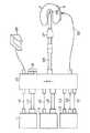
図17および図18を参照して第13実施形態を説明する。図17はこの第13実施形態のシステムの構成を示し、図18はそのミキサーの重要部分を示すものである。
【0116】
このシステムでは特に同軸出力高周波発振器を2台、2線出力高周波発振器を1台設けたものである。つまり、第1周波数同軸出力高周波発振器111と、第2周波数同軸出力高周波発振器112と、2線出力高周波発振器113を備えており、それぞれにはフットスイッチ・ケーブル114,115,116が接続されている。また、第1周波数同軸出力高周波発振器111には中継同軸ケーブル117が接続され、第2周波数同軸出力高周波発振器112には中継同軸ケーブル118が接続されている。2線出力高周波発振器113には中継プレート・ケーブル121と中継アクティブ・ケーブル122が接続される。
【0117】
そして、全てのケーブルはミキサー123に接続される。ミキサー123にはアプリケータ・ケーブル124と高周波プレート・ケーブル125と、両用1連フットスイッチ126が接続される。アプリケータ・ケーブル124の他端にはアプリケータ127が接続される。アプリケータ127の先端処置部128を患者9の治療部位に接触させる。また、高周波プレート・ケーブル125には高周波患者プレート8が接続され、高周波患者プレート8は患者9に装着されるようになっている。
【0118】
また、ミキサー123にはセレクト・ボタン130が設けられており、これによって、フットスイッチ126を踏んだ時にどの周波数の高周波発振器を発振させるかを選択させる。
【0119】
図18で示すように前記ミキサー123の内部に設けられるミキシング部分は2つの同軸出力高周波と1つの2線出力高周波を合流させる構成であり、それぞれの同軸出力高周波発振器にコネクタを介してそれぞれ接続する第1周波数発振器側同軸ケーブル131と第2周波数発振器側同軸ケーブル132は分岐同軸コネクタ133に接続されて合流し、同軸出力発振器側ケーブル134にまとめられる。この同軸出力発振器側ケーブル134には高周波電流カット用フェライトコア135が装着されている。同軸出力発振器側ケーブル134はフランジ付同軸コネクタ136を介してアプリケータ側ケーブル137に接続される。また、2線出力高周波発振器2に接続されている中継アクティブ・ケーブル122にコネクタを介して接続される2線出力発振器側ケーブル138が同軸コネクタ136の外部導体を介して電気的に接続されているフランジ139に電気的に接続される。
【0120】
このシステムの実際の使用法についてはこれまでの実施形態と同じであり、それから理解されるであろう。
この実施形態によれば、3つ以上の高周波発振器を接続して、同一のアプリケータでこの3つ以上の高周波メスの効果を発揮させることが可能となる。さらに、今までの実施形態との組み合わせで、同軸出力は1つで2線出力が2つの3つ以上の発振器の組み合わせや、4つ以上の発振器の組み合わせも可能である。また、同軸出力だけの組み合わせなど、全ての組み合わせがこの実施形態の延長上にあり、含まれるものとなる。
【0121】
患者の適用部位としては、頭頸部、胸部、腹部、腰部、上下肢等あらゆる外科手術分野への適用が考えられる。また、気管支、食道、胃、胆管、腸、尿道等の管腔臓器への経内視鏡的外科手術、子宮、肝臓等実質臓器への腹腔鏡的手術へも適用できる。
【0122】
[付記]
(1)各々異なる周波数を発振する2つ以上の高周波発振器と、これらの高周波発振器に接続され、それらの高周波発振器の電力を伝送する伝送ケーブルと、この伝送ケーブルに前記各高周波発振器から与えられる電力を生体にそれぞれ供給して高周波外科的処置を行うアプリケータと、前記伝送ケーブルが電気的に接続され、2つ以上の前記高周波発振器からの異なる周波数の複数の電力の1つ以上を選択してこの電力を前記アプリケータを用いて生体にそれぞれ供給するための手段とを備えたことを特徴とする異周波数高周波処置システム。
【0123】
(2)各々異なる周波数を発振する2つ以上の高周波発振器と、この高周波発振器の電力を伝送する伝送ケーブルと、この伝送ケーブルから与えられる電力を生体に供給するアプリケータとを備え、さらに前記複数の高周波発振器に接続されている前記伝送ケーブルが電気的に接続され、前記高周波発振器から複数の周波数の電力が供給されたとき、これらの電力を同一の前記アプリケータを通じて生体に同時または選択的に供給させる(合流)手段を具備したことを特徴とする異周波数高周波ブレンド処置システム。
【0124】
(3)同軸出力の高周波発振器と、同軸ケーブルよりなる伝送ケーブルと、生体に同軸出力の高周波電力を与えるアンテナを有するアプリケータと、2線出力の高周波発振器と、2線出力の高周波電力を伝送するための2本の伝送ケーブルとを備え、2線出力の高周波電力を伝送する2本の伝送ケーブルのうちの1本は前記同軸ケーブルよりなる伝送ケーブルの少なくとも一方の導電線に電気的に接続されていることを特徴とする付記第1、2項に記載の異周波数高周波ブレンド処置システム。
【0125】
(4)異なる周波数の2線出力をそれぞれ出力する複数の高周波発振器と、前記複数の高周波発振器の電力を伝送する伝送ケーブルと、生体に高周波電力を供給するためのアプリケータとを備え、さらに前記複数の異なる周波数の高周波電力を同一の前記アプリケータで生体に供給するために前記複数の高周波発振器に同一のアプリケータを電気的に接続する伝送ケーブルを設けたことを特徴とする付記第1、2項に記載の異周波数高周波ブレンド処置システム。
【0126】
(5)同軸出力の高周波発振器と、2線出力の高周波発振器と、前記2つの高周波発振器の出力を同一の伝送ケーブルに送り込むミキサーと、生体に高周波出力を与える同軸ケーブルを前記伝送ケーブルとして有するアプリケータがあり、前記ミキサーは、前記同軸出力の高周波発振器の出力を伝送する同軸ケーブルの外部導体に、2線出力の高周波電力を伝送するための2本の伝送ケーブルのうちの1本のラインが電気的に接続されており、もう1本のラインは生体に装着するプレート電源に接続されていることを特徴とする付記第3項に記載の異周波数高周波ブレンド処置システム(第1,2実施形態)。
【0127】
(6)同軸出力の高周波発振器と、2線出力の高周波発振器と、前記2つの高周波発振器の出力を合成するためのミキサーと、生体に高周波出力を与える同軸ケーブルを伝送ケーブルとして有するアプリケータがあり、前記ミキサーは、前記同軸出力の高周波発振器の出力を伝送する同軸ケーブルの内部導体に、2線出力の高周波電力を伝送するための2本の伝送ケーブルのうちの1本のラインが電気的に接続されており、もう1本のラインは生体に装着するプレート電源に接続されていることを特徴とする付記第3項に記載の異周波数高周波ブレンド処置システム(第3実施形態)。
【0128】
(7)同軸出力の高周波発振器の出力を伝送する同軸ケーブルと、2線出力の高周波発振器の電力を伝送する2本のケーブルのうちの1本が電気的に接続される場所と、同軸出力の高周波発振器との間の同軸ケーブルにフェライトコア等の磁性体が装着されていることを特徴とする付記第5,6項に記載の異周波数高周波ブレンド処置システム(第1,2,3実施形態)。
【0129】
(8)2つの2線出力の高周波発振器と、前記2つの高周波発振器の出力を合成するためのミキサーと、生体に高周波出力を与えるアプリケータと、患者に装着するプレート電源があり、ミキサーにて、それぞれの高周波発振器の出力のアクティブ側同士とプレート側同士を別々にそれぞれ電気的に接続していることを特徴とする付記第4項に記載の異周波数高周波ブレンド処置システム(第9実施形態)。
【0130】
(9)2つの高周波発振器の出力のケーブルが電気的に接続される場所と、高周波発振器の間にバンドパスフィルタまたはアイソレーターが設けられていることを特徴とする付記第8項に記載の異周波数高周波ブレンド処置システム(第9実施形態)。
【0131】
(10)ミキサーに接続される複数の高周波発振器のON/OFFを制御する遠隔スイッチを接続するケーブルが、ミキサーに接続されるようになっており、ミキサー内で信号処理された上で各発振器にON/OFF信号として送信されていることを特徴とする付記第5、6、8項に記載の異周波数高周波ブレンド処置システム(第4,10実施形態)。
【0132】
(11)アプリケータに高周波電力を供給する複数の高周波発振器のうちの1つにミキサーが内蔵されていることを特徴とする付記第5、6、8項に記載の異周波数高周波ブレンド処置システム(第5,6,11実施形態)。
【0133】
(12)高周波発振器の出力のアクティブ側同士をアプリケータ内で電気的に接続し、プレート側同士をプレート電極にて電気的に接続していることを特徴とする付記第8項に記載の異周波数高周波ブレンド処置システム(第12実施形態)。
【0134】
【発明の効果】
以上説明したように本発明によれば、同一のアプリケータを用いて異なる周波数の複数の高周波で処置することが可能となる。さらに異なる周波数の高周波処置の効果を同時に発生させることが可能となる。例えば切開能力に優れていると言われている電気メスと、凝固・止血能力に優れていると言われているマイクロ波メスの、2つの能力を同時に出力することが可能となり、よりスピーディーでかつ安全で出血の少ない新しい電気メスとしての使用が可能となる。このように複数の異なる周波数の複数の高周波メスの能力を同時に使用することが可能となり、今までに無い高い能力を備えた高周波メスの使用が可能となる。
その他にも、数百キロHzで切開/止血を行い、ギガHz帯で患部(癌細胞等)を凝固・死滅させる等、いろいろな用途のバリエーションがあるが、複数の周波数の高周波メスを使用することによる利点が発生する使用法全てがこの考案の対象となろう。特に同時に複数の周波数を発生させたい使用法がよりマッチした使用法である。
【図面の簡単な説明】
【図1】第1実施形態のシステム構成の概略的な説明図。
【図2】同じくその第1実施形態のミキサー部分の側面図。
【図3】同じくその第1実施形態のアプリケータの先端部分の断面図。
【図4】第2実施形態のミキサー部分の斜視図。
【図5】第3実施形態のミキサー部分の斜視図。
【図6】第4実施形態のセレクト・ボタンの部分の周面図。
【図7】第4実施形態のシステム構成の概略的な説明図。
【図8】第5実施形態のシステム構成の概略的な説明図。
【図9】第6実施形態のシステム構成の概略的な説明図。
【図10】第7実施形態のフットスイッチの説明図。
【図11】第8実施形態の発振の組み合わせ状態を示すタイムチャート。
【図12】第9実施形態のシステム構成の概略的な説明図。
【図13】同じく第9実施形態のミキサー部分の説明図。
【図14】第10実施形態のシステム構成の概略的な説明図。
【図15】第11実施形態のシステム構成の概略的な説明図。
【図16】第12実施形態のシステム構成の概略的な説明図。
【図17】第13実施形態のシステム構成の概略的な説明図。
【図18】同じく第13実施形態のミキサー部分の説明図。
【符号の説明】
1…同軸出力高周波発振器、2…2線出力高周波発振器、3…同軸出力高周波用フットスイッチ、4…中継同軸ケーブル、5…2線出力高周波用フットスイッチ、6…高周波プレート・ケーブル、7…中継アクティブ・ケーブル、8…高周波患者プレート、9…患者、11…ミキサー、12…アプリケータ・ケーブル、13…アプリケータ、15…同軸出力発振器側ケーブル、16…アプリケータ側ケーブル、18…フランジ付同軸コネクタ、21…2線出力発振器側ケーブル、22…高周波電流遮断用フェライトコア、25…内部導体、26…外部導体。[0001]
BACKGROUND OF THE INVENTION
The present invention performs a surgical procedure by supplying electric power from two or more frequency oscillators each oscillating at different frequencies to a living body by an applicator.Treatment system About.
[0002]
[Prior art]
In USP No. 4,188,927, a system for simultaneously supplying high frequencies of different frequencies to a living body is disclosed. In this system, the frequency component of the high-frequency current flowing in the living body has different frequencies, and AM-modulated high-frequency flows. This is different from that in which different frequencies flow separately. In addition, for any frequency, an attempt is made to flow an AM-modulated high-frequency current to a living body using a pair of the same electrodes.
[0003]
In this method, since an AM-modulated high-frequency current is to flow, there is a practical technical limit to the transmission of components for the higher frequency. If it is a frequency up to several tens of MHz, this method can be effectively supplied to a living body as it is, but it has not been possible to handle high frequencies beyond that. However, a higher frequency high-frequency current is effective for coagulation of a living body, but this method cannot effectively handle such a high-frequency high-frequency current.
[0004]
In the Surgical Clinical Handbook “Frontier of Endoscopic Surgery” (issued by Nakayama Shoten in '94 .6.10), high frequency currents of different frequencies are selectively transmitted from the same applicator by means of switching to solve the above-mentioned problems. This is designed to output, and it is impossible to simultaneously pass high-frequency currents having different frequencies.
[0005]
[Problems to be solved by the invention]
Conventionally, it has been known that, for example, a high-frequency knife has an incision ability, but a coagulation ability is superior to a microwave knife, and has characteristics of frequency and power at that frequency. If each superior ability can be used with the same applicator, it can be used as the best system.
[0006]
The above contents are embodied, and a high frequency knife and microwave knife are given to a common applicator by simply switching between a high frequency and a microwave using a changeover switch, or a plurality of high frequency oscillators that magnetically apply the applicator. Although the method of connecting to is already published as a research publication or patent, this system also cannot reliably output multiple high frequencies simultaneously. In particular, it is still untouched to produce a coaxial output high frequency and a two-wire output high frequency simultaneously.
[0007]
Therefore, it corresponds to the blend mode (incision + coagulation) of the conventional high-frequency knife, and there is no blend of high frequencies of a plurality of frequencies.
[0008]
The present invention has been made paying attention to the above-mentioned problems, and the object of the present invention is two or more different with the same applicator.Have ability Each power to the living body can be demonstrated using power of frequencyTreatment system Is to provide.
[0009]
[Means for Solving the Problems]
The present invention provides a coaxial outputHigh frequency microwave First to oscillatehigh frequency An oscillator,Said Firsthigh frequency Oscillator outputsHigh frequency of coaxial output Coaxial cable for transmitting power and 2-wire outputhigh frequency The second to outputhigh frequency An oscillator and the secondhigh frequency OscillatorOutput 2-wire outputhigh frequency Two cables to transmit power,The high-frequency output antenna portion for the coaxial output is formed by the tip portion of the inner conductor of the coaxial cable and the tip of the outer conductor of the coaxial cable protruding so as to be exposed from the tip of the coaxial cable. Form an active electrode for high frequency output of line output, Of the coaxial outputhigh frequency Of power and the two-wire outputhigh frequency An applicator for performing a surgical procedure to simultaneously apply power to a living body;high frequency Electrically connecting the coaxial cable to an oscillator;In two cables that transmit high-frequency power of the two-wire output One cableFor the inner conductor or outer conductor of the coaxial cable Electrically connected, saidElectrically connect the other of the two cables to a plate for high-frequency current recovery mounted on the patient's body surface; The firsthigh frequency OscillatorOutput high frequency power And the secondhigh frequency OscillatorOutput high frequency power And a supply means adapted to supply both to the applicator through the coaxial cable at the same time.
Thus, the same applicator has a plurality of treatment capabilities. Furthermore, since a plurality of outputs are simultaneously applied to perform the treatment, the respective capabilities are combined, and incision and coagulation / hemostasis can be performed simultaneously with the same applicator.
[0010]
DETAILED DESCRIPTION OF THE INVENTION
<First Embodiment>
The first embodiment will be described with reference to FIGS. 1 to 3. FIG. 1 shows a schematic system configuration of the embodiment, FIG. 2 shows an important part of the mixer, and FIG. 3 shows a tip part of the applicator.
[0011]
As a high-frequency power source in this system, two oscillators, a coaxial output high-frequency oscillator 1 and a two-wire output high-
[0012]
The relay
[0013]
The mixer 11 joins the high frequency of the two-wire output and the high frequency of the coaxial output to the applicator output system, and the structure of this mixing portion is configured as shown in FIG. That is, a coaxial output
[0014]
In the flanged
[0015]
Thus, the merging means is configured to select one or more of the plurality of electric powers having different frequencies and supply the electric power to the living body using the
[0016]
In addition, in the mixer 11, a
[0017]
Further, as shown in FIG. 3, the
In the coaxial cable, an
[0018]
Next, the practical usage of this system and the operation at that time will be described. First, in use, each part is connected and prepared as shown in FIG. The
[0019]
Therefore, when performing incision and coagulation by applying a high-frequency current to the affected area, the 2-wire output high-
2-wire output high-frequency oscillator 2-> relay active cable 7-> mixer 11 (2-wire output oscillator side cable 21-> flange 17 of
[0020]
The high frequency current flows from the outer conductor to the inner conductor of the
[0021]
Further, when coagulation is performed by radiating coaxial output high-frequency power to the affected area, the coaxial output high-
Coaxial output high frequency oscillator 1-> relay coaxial cable 4-> Misa key 11 (coaxial output oscillator side cable 15-> flanged coaxial connector 18-> applicator side cable 16)-> applicator cable 12->
[0022]
Further, when the 2-wire output high-frequency power and the coaxial output high-frequency are simultaneously applied to the affected part of the
[0023]
The high-frequency current is prevented from flowing from the two-wire output
[0024]
According to the above configuration, the
[0025]
In addition, there are various uses such as incision and hemostasis with a two-wire output high-frequency knife, and coagulation and death of the affected area (cancer cells, etc.) with a coaxial output high-frequency knife. All usages that benefit from the use of both high frequency scalpels will be the subject of this embodiment. In particular, the usage that wants to simultaneously generate a two-wire output high-frequency knife and a coaxial output high-frequency knife is a more matched usage.
[0026]
In addition, with this system, it is only necessary to purchase a mixer, a part of the connection cable, and an applicator only, using the two-wire output high-frequency oscillator and coaxial output high-frequency oscillator already owned by the user. The system can be constructed at low cost.
[0027]
<Second Embodiment>
A second embodiment will be described with reference to FIG. This shows a
[0028]
The method of using the system of the second embodiment is the same as that of the first embodiment described above.
According to this embodiment, the effect is the same as that of the first embodiment described above, and it is not necessary to attach a special coaxial connector with a flange, and the number of parts can be reduced. Further, by reducing the size of the uncovered cable portion 32, the portion where the active electrode line of the two-wire output high-frequency oscillator is exposed can be reduced, and a serviceman or the like is operated with the mixer 11 opened. The safety of the case is improved.
[0029]
<Third Embodiment>
A third embodiment will be described with reference to FIG. This shows a coaxial connector portion of the mixer portion different from the first embodiment described above. That is, the branching
[0030]
This method of use is the same as in the first embodiment, but the route through which the two-wire output high-frequency current flows is different. The two-wire output oscillator-
[0031]
In the case of this embodiment, since the so-called mixing is performed without using the capacitance of the
[0032]
<Fourth Embodiment>
A fourth embodiment will be described with reference to FIGS. 6 and 7. FIG. 6 shows an example of the select button, and FIG. 7 is an explanatory diagram of the system configuration.
The power source in the system of this embodiment includes two oscillators, a coaxial output high frequency oscillator 1 and a two-wire output
[0033]
Each high frequency supplied through the relay
[0034]
The
[0035]
An
[0036]
An example of the
[0037]
Inside the
[0038]
Next, the actual usage of this system is shown as an example of combination of microwave and high frequency. First, each part is connected as shown in FIG. Then, the
[0039]
First, when performing incision / coagulation by passing a two-wire output high-frequency current to the affected area, the mode of only the high frequency is selected by the select
[0040]
The two-wire output high-frequency current flows from the outer conductor to the inner conductor of the
[0041]
When coagulation is performed by radiating coaxial output high frequency to the affected area, the select
[0042]
These two types of high frequencies can be simultaneously applied to the affected area of the
[0043]
According to this embodiment, in addition to the effects of the first embodiment, the following two effects are also achieved.
One of them is that the cables from the coaxial output high-frequency oscillator 1 and the two-wire output high-
[0044]
The other is the output mode setting function with the select button, so that the output ON / OFF control of the two-wire output high frequency and the coaxial output high frequency can be performed with a
[0045]
In this embodiment, the control function of the coaxial output high-frequency oscillator 1 and the two-wire output high-
[0046]
<Fifth Embodiment>
A fifth embodiment will be described with reference to FIG. FIG. 8 shows the system configuration. The power source in the system of this embodiment also includes two oscillators, a coaxial output high-frequency oscillator 1 and a two-wire output high-
[0047]
The coaxial output high-frequency oscillator 1 is connected to a relay
[0048]
A high-frequency oscillator and a mixer are provided inside the two-wire output high-
[0049]
Next, the actual usage of this embodiment will be described. First, each part is connected as shown in FIG. A high frequency
[0050]
Therefore, when incising and coagulating by passing a two-wire output high-frequency current through the affected area, by stepping on one petal of the dual-use
Here, the high-frequency current flowing from the outer conductor to the inner conductor of the
[0051]
When coagulation is performed by radiating the coaxial output high frequency to the affected area, the coaxial output high frequency oscillator 1 starts oscillating by stepping on one petal of the dual
[0052]
It is possible to simultaneously apply the two-wire output high frequency and the coaxial output high frequency to the affected part of the
[0053]
Inside the two-wire output high-
[0054]
In this embodiment, the effects of the first embodiment are the same except that a commercially available high-frequency oscillator can be used, and the system is most efficiently constructed for those who have only a coaxial output high-frequency oscillator. It becomes a style that can. Further, since the routing of the cables on the two-wire output high frequency side where problems are likely to occur due to the routing of the cables can be reduced, the safety is improved.
[0055]
Further, by using the dual-use
[0056]
The dual-use
[0057]
<Sixth Embodiment>
The sixth embodiment will be described with reference to FIG. FIG. 9 shows the system configuration. The power source in the system of this embodiment also includes two oscillators, a coaxial output high-frequency oscillator 1 and a two-wire output high-
[0058]
The two-wire output high-
[0059]
An
[0060]
The other end of the
[0061]
In addition to the coaxial output high frequency and two-wire output high frequency mixing mechanism disclosed in the first to third embodiments, the coaxial output high frequency oscillator 1 in the mixer has a coaxial output high frequency oscillator, and a hand switch. A circuit is provided for sending the ON signal from 62 to the 2-wire output high-
[0062]
Next, the actual usage of this embodiment system will be described. Each part is connected as shown in FIG. The
[0063]
If the mixing mechanism in the coaxial output high-frequency oscillator 1 with a built-in mixer is the same as that in the first embodiment, the route through which the high-frequency current flows is the same as that of the first embodiment. Mixer in coaxial output high frequency oscillator 1-> outer conductor of applicator cable 12-> inner conductor of applicator cable 12->
[0064]
When coagulation is performed by radiating the coaxial output high frequency to the affected area, the coaxial output high frequency oscillator in the coaxial output high frequency oscillator 1 built in the mixer starts oscillating by pressing the coaxial output high frequency switch button of the
[0065]
The transmission route at this time is as follows: coaxial output high-frequency oscillator in the coaxial output high-frequency oscillator 1 with built-in mixer-> missa key in coaxial output high-frequency oscillator 1 with built-in mixer-> applicator cable 12-> applicator with
[0066]
In order to simultaneously apply the two-wire output high frequency and the coaxial output high frequency to the affected part of the
[0067]
In this embodiment, the effect of the first embodiment is the same except that a commercially available coaxial output high-frequency oscillator can be used, and is most efficient for a person who has only a two-wire output high-frequency oscillator. It becomes a style that can build a system. In particular, since the two-wire output high-frequency knife is currently used as a standard in various operations, the advantage that an existing two-wire output high-frequency transmitter can be used is actually very large. Further, the coaxial output high-frequency knife is not as widespread as the two-wire output high-frequency knife, and since it is integrated with the mixer, there is no waste in a new purchase.
[0068]
In addition, by using the hand switch, the user can perform ON / OFF operation with the applicator at hand, which is very convenient compared to the foot switch. Of course, you won't have to look for a footswitch or step on it by mistake.
[0069]
The hand switch is not an essential condition of this embodiment, and a dual-use dual foot switch may be used as in the fifth embodiment, or a select button and a single foot switch may be used as in the fourth embodiment. A hand switch may be used in the fourth and fifth embodiments. Further, it is also included in the combination range of these embodiments to provide a single hand switch and provide a select button.
In addition, although the description about the mixing mechanism was performed in the mechanism of 1st Embodiment, it is not limited to it.
[0070]
<Seventh embodiment>
The seventh embodiment will be described with reference to FIG. This embodiment is a modification of the foot switch, and any other system of the first to sixth embodiments may be used for other systems.
[0071]
As shown in FIG. 10, the foot switch of this embodiment is a two-stage push-type foot switch 65. This means that once the
[0072]
In the first-stage pushing operation, only the coaxial output high frequency oscillates, and the two-wire output high frequency does not oscillate. Further, in the pushing operation of the second step, the two-wire output high frequency is oscillated together with the coaxial output high frequency, and an output in which the coaxial output high frequency and the two-wire output high frequency are mixed is supplied to the
[0073]
Moreover, in this embodiment, hemostasis is not performed with a two-wire output high-frequency knife, but hemostasis is usually performed with a coaxial output high-frequency knife having excellent coagulation ability, and incision is performed by oscillating the two-wire output high-frequency knife. It is intended for use that always oscillates the coaxial output high frequency at the same time. In that case, it is not used only by the two-wire output high frequency knife, and the coaxial output high frequency is always oscillated. Then, in order to make an incision, the two-step push foot switch is fully depressed, both are oscillated, and the incision is performed while hemostasis is stopped. After that, return the foot switch a little to the first stage to stop bleeding for the shortage. In addition, when coagulating and killing an affected part such as a cancer cell, the foot switch is tapped to oscillate only the coaxial output high frequency to perform coagulation.
[0074]
As an effect of this embodiment, under the above use conditions, a single foot switch can be used without mistakes, without extra operation, and continuous treatment operations can be performed.
[0075]
The two-stage push type foot switch here may be a two-stage push hand switch.
[0076]
<Eighth Embodiment>
The eighth embodiment will be described with reference to FIG. FIG. 11 shows a combination of oscillations in the eighth embodiment. In addition, regarding this system, any of the first to sixth embodiments may be cited.
[0077]
That is, in this oscillation mode, when a series of foot switches (or hand switches) is pressed, a two-wire output high frequency is oscillated. When the switch is released and the high frequency is turned off, the coaxial output high frequency (microwave) is immediately oscillated.
According to this, first, the incision is performed by oscillating the two-wire output high frequency, and when it is stopped, the hemostasis automatically starts at the coaxial output high frequency.
[0078]
Thereby, a series of operations of incision and hemostasis at different frequencies can be performed by a single push-off operation of one foot switch.
In addition, when the high frequency for incision is oscillated, the high frequency for hemostasis is also oscillated at the same time. Can also be performed automatically.
[0079]
<Ninth Embodiment>
A ninth embodiment will be described with reference to FIGS. 12 and 13. FIG. 12 shows the system configuration of the ninth embodiment, and FIG. 13 shows the important part of the mixer.
[0080]
In this system, two 2-wire output high-frequency oscillators are provided. That is, the first frequency two-line output high-frequency oscillator 71 and the second frequency two-line output high-
[0081]
The
[0082]
The
[0083]
Next, the actual usage of the system of the ninth embodiment will be shown. First, as shown in FIG. 12, each part is connected and prepared. Then, the
[0084]
In order to perform treatment at each frequency (incision, coagulation, hemostasis, transpiration, etc.), the foot switches 73 and 74 at the respective frequencies are stepped on to start the oscillation of the
Further, high frequency power of two frequencies can be applied to the affected area of the
[0085]
As shown in FIG. 13, bandpass filters (or isolators) 87 and 88 are inserted in the lines from the respective frequency oscillators, so that one high-frequency current can pass from the
[0086]
Note that the bandpass filters (or isolators) 87 and 88 are not necessarily required, and may be present. Even without this, the role of the
[0087]
This makes it possible to use the
[0088]
In addition, there are various application variations such as incision and hemostasis on the one hand and coagulation and death of the affected part (cancer cells etc.) on the other side, but use a two-wire output high frequency knife with two frequencies. Any use that would benefit from this would be the subject of this embodiment. In particular, the usage that wants to generate the effect of two two-wire output high-frequency knife simultaneously is a more matched usage.
[0089]
Further, with this system, it is only necessary to purchase a new mixer and a connecting cable by using a high-frequency oscillator already owned by the user as it is, and the system can be constructed at a very low cost.
[0090]
<Tenth Embodiment>
The tenth embodiment will be described with reference to FIG. FIG. 14 shows a system diagram of the tenth embodiment.
[0091]
In this system, two 2-wire output high-frequency oscillators are provided. That is, a first frequency two-line output high-frequency oscillator 71 and a second frequency two-line output high-
[0092]
Further, the
[0093]
Inside the
[0094]
The form of the
[0095]
Next, the actual usage of this embodiment system will be described. As shown in FIG. 14, each part is connected and prepared. The
[0096]
First, when the second line output high-frequency current of the first frequency is passed through the affected area, the
[0097]
Further, when the second line output high-frequency current of the second frequency is passed through the affected area, the
[0098]
In order to simultaneously apply the high frequency of these two frequencies to the affected part of the
[0099]
According to this embodiment, in addition to the effects of the ninth embodiment described above, the following two effects are added.
One of them is that if the cables from the two high-
[0100]
Second, the output mode setting function with the
[0101]
In this embodiment, the control function of the high-frequency oscillator by the
[0102]
<Eleventh embodiment>
The eleventh embodiment will be described with reference to FIG. FIG. 15 is a system diagram of the eleventh embodiment.
In this system, a first frequency two-line output high-frequency oscillator 71 is connected to a first frequency oscillator
[0103]
An applicator 98 with a hand switch is connected to the other end of the
[0104]
The other end of the hand switch cable 97 connected to the mixer built-in second frequency 2-line output high frequency oscillator 96 is connected to an applicator 98 with a hand switch and connected to a hand switch 99 provided in the applicator 98. . A high frequency ON / OFF signal of a frequency designated by the user by the hand switch 99 is input to the mixer built-in second frequency 2-wire output high frequency oscillator 96 via the hand switch cable 97.
[0105]
Next, the actual usage of this embodiment system will be described. As shown in FIG. 15, each part is connected and prepared.
The distal treatment section of the applicator 98 with hand switch is brought into contact with the affected area of the
[0106]
First, when the two-wire output high-frequency current of the first frequency is passed through the affected part, the first-frequency two-wire output high-frequency oscillator 71 starts oscillating by pressing the first frequency switch of the hand switch 99. While pressing, a high-frequency current of the first frequency flows.
[0107]
In addition, when the 2-wire output high-frequency current of the second frequency is passed through the affected area, the oscillation of the 2-wire output high-frequency oscillator 96 of the second frequency is started by pressing the second frequency switch of the hand switch. While the switch is pressed, a high-frequency current having the second frequency flows.
[0108]
In order to simultaneously apply the high frequencies of these two frequencies to the affected area of the
[0109]
In this embodiment, it becomes a style in which a system can be constructed most efficiently for a person who has a two-wire output high-frequency oscillator of one frequency. In particular, since a two-wire output high frequency knife of several hundreds of kilohertz is currently used as a standard in various operations, the advantage that an existing two-wire output high frequency transmitter can be used for one frequency is a reality. It ’s very big. In addition, high frequency scalpels of other frequencies are not so widespread, and since this is integrated with the mixer, there is no waste in new purchases.
[0110]
Further, the use of the hand switch 99 allows the user to perform an ON / OFF operation with the applicator 98 at hand, which is very convenient compared to a foot switch. Of course, you won't have to look for a footswitch or step on it by mistake.
[0111]
The hand switch is not an essential condition of this embodiment, and various types of foot switches and the like may be used as in other embodiments. Further, it is also included in the combination range of these embodiments to provide a single hand switch and provide a select button.
[0112]
<Twelfth embodiment>
A twelfth embodiment will be described with reference to FIG. FIG. 16 is a system diagram of the twelfth embodiment.
In the system of this embodiment, the functions of the mixer in the ninth embodiment described above are distributed to the applicator and the patient plate.
[0113]
That is, a first frequency 2-line output high-frequency oscillator 71 and a second frequency 2-line output high-
[0114]
In this embodiment, the mixer function is distributed over the
[0115]
<13th Embodiment>
A thirteenth embodiment will be described with reference to FIGS. 17 and 18. FIG. 17 shows a system configuration of the thirteenth embodiment, and FIG. 18 shows an important part of the mixer.
[0116]
In this system, in particular, two coaxial output high-frequency oscillators and one two-wire output high-frequency oscillator are provided. That is, a first frequency coaxial output high-frequency oscillator 111, a second frequency coaxial output high-
[0117]
All cables are connected to the
[0118]
The
[0119]
As shown in FIG. 18, the mixing portion provided in the
[0120]
The actual use of this system is the same as in the previous embodiments and will be understood therefrom.
According to this embodiment, it is possible to connect three or more high-frequency oscillators so that the effect of the three or more high-frequency scalpels can be exhibited with the same applicator. Further, in combination with the above embodiments, a combination of three or more oscillators having one coaxial output and two two-wire outputs, or a combination of four or more oscillators is possible. Further, all combinations such as a combination of only coaxial outputs are included in the extension of this embodiment and are included.
[0121]
As the application site of the patient, application to all surgical fields such as the head and neck, the chest, the abdomen, the lumbar region, and the upper and lower limbs can be considered. It can also be applied to transendoscopic surgery on luminal organs such as bronchi, esophagus, stomach, bile duct, intestine and urethra, and laparoscopic surgery on parenchymal organs such as uterus and liver.
[0122]
[Appendix]
(1) Two or more high-frequency oscillators that oscillate at different frequencies, transmission cables that are connected to these high-frequency oscillators and transmit the power of these high-frequency oscillators, and power that is supplied from the high-frequency oscillators to the transmission cables An applicator for performing high frequency surgical treatment by supplying each of the living body to the living body, and the transmission cable is electrically connected to select one or more of a plurality of electric powers of different frequencies from two or more high frequency oscillators. And a means for supplying the electric power to the living body using the applicator.
[0123]
(2) Two or more high-frequency oscillators that oscillate at different frequencies, a transmission cable that transmits power of the high-frequency oscillator, and an applicator that supplies power to the living body from the transmission cable, When the transmission cable connected to the high-frequency oscillator is electrically connected and power of a plurality of frequencies is supplied from the high-frequency oscillator, these powers are simultaneously or selectively transmitted to the living body through the same applicator. A different-frequency high-frequency blending treatment system comprising means for supplying (merging).
[0124]
(3) A coaxial output high-frequency oscillator, a transmission cable made of a coaxial cable, an applicator having an antenna that gives coaxial output high-frequency power to a living body, a two-wire output high-frequency oscillator, and a two-wire output high-frequency power One of the two transmission cables for transmitting the high-frequency power of the two-wire output is electrically connected to at least one of the conductive wires of the coaxial cable. The different-frequency high-frequency blending treatment system according to any one of
[0125]
(4) a plurality of high-frequency oscillators that respectively output two-wire outputs of different frequencies, a transmission cable that transmits power of the plurality of high-frequency oscillators, and an applicator for supplying high-frequency power to a living body,
[0126]
(5) An application having a coaxial output high-frequency oscillator, a two-wire output high-frequency oscillator, a mixer that sends the outputs of the two high-frequency oscillators into the same transmission cable, and a coaxial cable that gives a high-frequency output to a living body as the transmission cable The mixer has one line of two transmission cables for transmitting high-frequency power of two-wire output to an outer conductor of the coaxial cable that transmits the output of the high-frequency oscillator of coaxial output. The different frequency, high frequency blending treatment system according to
[0127]
(6) There is an applicator having a coaxial output high-frequency oscillator, a two-wire output high-frequency oscillator, a mixer for synthesizing the outputs of the two high-frequency oscillators, and a coaxial cable that gives a high-frequency output to a living body as a transmission cable. In the mixer, one line of two transmission cables for transmitting high-frequency power of two-wire output is electrically connected to the inner conductor of the coaxial cable that transmits the output of the high-frequency oscillator of coaxial output. 4. The different frequency high frequency blending treatment system according to
[0128]
(7) A coaxial cable for transmitting the output of the coaxial output high-frequency oscillator, a place where one of the two cables for transmitting the power of the two-wire output high-frequency oscillator is electrically connected, and the coaxial output The different-frequency high-frequency blending treatment system according to any one of
[0129]
(8) There are two two-wire output high-frequency oscillators, a mixer for synthesizing the outputs of the two high-frequency oscillators, an applicator for giving high-frequency outputs to the living body, and a plate power supply to be attached to the patient. The different frequency, high frequency blending treatment system according to
[0130]
(9) The different frequency according to
[0131]
(10) A cable for connecting a remote switch for controlling ON / OFF of a plurality of high-frequency oscillators connected to the mixer is connected to the mixer, and each oscillator is subjected to signal processing in the mixer. 9. The different-frequency high-frequency blending treatment system according to
[0132]
(11) The different-frequency high-frequency blending treatment system according to any of
[0133]
(12) The difference according to
[0134]
【The invention's effect】
As described above, according to the present invention, it is possible to perform treatment at a plurality of high frequencies having different frequencies using the same applicator. Furthermore, it becomes possible to simultaneously generate the effects of high frequency treatments of different frequencies. For example, it is possible to output two abilities at the same time, an electric scalpel that is said to have excellent incision ability and a microwave scalpel that is said to be excellent in coagulation and hemostasis ability. It can be used as a new electric knife that is safe and has little bleeding. As described above, the capabilities of a plurality of high-frequency scalpels having a plurality of different frequencies can be used at the same time, and a high-frequency scalpel having a high capability that has never been achieved can be used.
In addition, there are various application variations such as incision / hemostasis at several hundred kilohertz and coagulation / death of the affected part (cancer cells, etc.) in the gigahertz band, but a high frequency scalpel with multiple frequencies is used. Any use that would benefit from this would be the subject of this invention. In particular, the usage that wants to generate a plurality of frequencies at the same time is a more matched usage.
[Brief description of the drawings]
FIG. 1 is a schematic explanatory diagram of a system configuration according to a first embodiment.
FIG. 2 is a side view of the mixer portion of the first embodiment.
FIG. 3 is a cross-sectional view of the distal end portion of the applicator according to the first embodiment.
FIG. 4 is a perspective view of a mixer portion according to a second embodiment.
FIG. 5 is a perspective view of a mixer portion according to a third embodiment.
FIG. 6 is a peripheral view of a select button portion according to a fourth embodiment.
FIG. 7 is a schematic explanatory diagram of a system configuration according to a fourth embodiment.
FIG. 8 is a schematic explanatory diagram of a system configuration according to a fifth embodiment.
FIG. 9 is a schematic explanatory diagram of a system configuration according to a sixth embodiment.
FIG. 10 is an explanatory diagram of a foot switch according to a seventh embodiment.
FIG. 11 is a time chart showing an oscillation combination state according to the eighth embodiment.
FIG. 12 is a schematic explanatory diagram of a system configuration according to a ninth embodiment.
FIG. 13 is an explanatory diagram of a mixer portion of the ninth embodiment.
FIG. 14 is a schematic explanatory diagram of a system configuration according to a tenth embodiment.
FIG. 15 is a schematic explanatory diagram of a system configuration according to an eleventh embodiment.
FIG. 16 is a schematic explanatory diagram of a system configuration according to a twelfth embodiment.
FIG. 17 is a schematic explanatory diagram of a system configuration according to a thirteenth embodiment.
FIG. 18 is an explanatory diagram of a mixer portion of the thirteenth embodiment.
[Explanation of symbols]
DESCRIPTION OF SYMBOLS 1 ... Coaxial output high frequency oscillator, 2 ... Two wire output high frequency oscillator, 3 ... Coaxial output high frequency foot switch, 4 ... Relay coaxial cable, 5 ... Two wire output high frequency foot switch, 6 ... High frequency plate cable, 7 ... Relay Active cable, 8 ... high frequency patient plate, 9 ... patient, 11 ... mixer, 12 ... applicator cable, 13 ... applicator, 15 ... coaxial output oscillator side cable, 16 ... applicator side cable, 18 ... coaxial with flange Connector, 21 ... two-wire output oscillator side cable, 22 ... high frequency current blocking ferrite core, 25 ... inner conductor, 26 ... outer conductor.
Claims (1)
Translated fromJapanese前記第1の高周波発振器が出力する同軸出力の高周波電力を伝送する同軸ケーブルと、
2線出力の高周波を出力する第2の高周波発振器と、
前記第2の高周波発振器が出力する2線出力の高周波電力を伝送するための2本のケーブルと、
前記同軸ケーブルの先端から露出するように突き出した前記同軸ケーブルの内部導体の先端部と前記同軸ケーブルの外部導体の先端により前記同軸出力の高周波出力用アンテナ部を形成し、前記先端部により前記2線出力の高周波出力のアクティブ電極を形成し、前記同軸出力の高周波電力と前記2線出力の高周波電力の両方を生体に同時に与える外科的処置を行うアプリケータと、
前記第1の高周波発振器に前記同軸ケーブルを電気的に接続すると共に、前記2線出力の高周波電力を伝送する2本のケーブルにおける一方のケーブルを前記同軸ケーブルの内部導体または外部導体に電気的に接続し、前記2本のケーブルにおける他方のケーブルを患者の体表面に装着される高周波電流回収用プレートに対し電気的に接続し、前記第1の高周波発振器が出力する高周波電力と前記第2の高周波発振器が出力する高周波電力との両方を、同時に前記同軸ケーブルを通じて前記アプリケータに供給するようにした供給手段と、
を備えたことを特徴とする異周波数同時処置システム。A firsthigh-frequency oscillator that oscillates amicrowave that is ahigh frequency of a coaxial output;
A coaxial cable for transmitting ahigh-frequency powerof a coaxialoutputsaid firsthigh-frequency oscillator output,
A secondhigh-frequency oscillator that outputs a two-wire outputhigh frequency ;
Two cables for transmitting two-wire outputhigh-frequency poweroutput from the secondhigh-frequency oscillator;
The high-frequency output antenna portion for the coaxial output is formed by the tip portion of the inner conductor of the coaxial cable and the tip of the outer conductor of the coaxial cable protruding so as to be exposed from the tip of the coaxial cable. An applicatorfor forming a high frequency output active electrode for line output, and performing a surgical procedure for simultaneously applying to the living body both thehigh frequency power of the coaxial output and thehigh frequency power of the two line output;
The coaxial cable is electrically connected to the firsthigh-frequency oscillator, and one ofthe two cables that transmit the high-frequency power of the two-wire output is electrically connected tothe inner conductor or the outer conductor of the coaxial cable. And connecting theother of the two cables to a high-frequency current collecting plate mounted on the patient's body surface, andthe high-frequency power output from the firsthigh-frequency oscillator and the second Supply means for supplying boththe high-frequency power output from the high-frequency oscillatorto the applicator through the coaxial cable at the same time;
A simultaneous treatment system for different frequencies characterized by comprising:
Priority Applications (1)
| Application Number | Priority Date | Filing Date | Title |
|---|---|---|---|
| JP19548295AJP3947577B2 (en) | 1995-07-31 | 1995-07-31 | Treatment system |
Applications Claiming Priority (1)
| Application Number | Priority Date | Filing Date | Title |
|---|---|---|---|
| JP19548295AJP3947577B2 (en) | 1995-07-31 | 1995-07-31 | Treatment system |
Publications (2)
| Publication Number | Publication Date |
|---|---|
| JPH0938102A JPH0938102A (en) | 1997-02-10 |
| JP3947577B2true JP3947577B2 (en) | 2007-07-25 |
Family
ID=16341826
Family Applications (1)
| Application Number | Title | Priority Date | Filing Date |
|---|---|---|---|
| JP19548295AExpired - Fee RelatedJP3947577B2 (en) | 1995-07-31 | 1995-07-31 | Treatment system |
Country Status (1)
| Country | Link |
|---|---|
| JP (1) | JP3947577B2 (en) |
Families Citing this family (2)
| Publication number | Priority date | Publication date | Assignee | Title |
|---|---|---|---|---|
| GB201021032D0 (en)* | 2010-12-10 | 2011-01-26 | Creo Medical Ltd | Electrosurgical apparatus |
| GB201321710D0 (en)* | 2013-12-09 | 2014-01-22 | Creo Medical Ltd | Electrosurgical apparatus |
- 1995
- 1995-07-31JPJP19548295Apatent/JP3947577B2/ennot_activeExpired - Fee Related
Also Published As
| Publication number | Publication date |
|---|---|
| JPH0938102A (en) | 1997-02-10 |
Similar Documents
| Publication | Publication Date | Title |
|---|---|---|
| JP6608477B2 (en) | Electrosurgical device for combined RF / microwave transmission | |
| EP3773288B1 (en) | Electrosurgical generator | |
| RU2709679C2 (en) | Bipolar electrosurgical actuator | |
| US7842033B2 (en) | Methods, systems, and devices for performing electrosurgical procedures | |
| US8449540B2 (en) | Electrosurgical pencil with improved controls | |
| KR101527918B1 (en) | 3-frequency electrosurgical instrument | |
| US5484434A (en) | Electrosurgical scalpel | |
| KR101229524B1 (en) | Electrosurgical instrument with enhanced capability | |
| CA2788397C (en) | Electrosurgical instrument and system | |
| KR102354441B1 (en) | Electrosurgical devices for delivering radio frequency energy and microwave energy and methods of using the same | |
| US20090264881A1 (en) | Ultrasonic surgical system | |
| US20160175047A1 (en) | Peripheral switching device for microwave energy platforms | |
| EP1050277A1 (en) | Dual-frequency electrosurgical instrument | |
| JP2012192242A (en) | Handheld electrosurgical instrument having disable handswitch | |
| CN102068307A (en) | Surgical unit with multifunctional handpiece | |
| JP2011529761A (en) | Electrosurgical instrument and electrosurgical system | |
| JP3947577B2 (en) | Treatment system | |
| CN212395036U (en) | Operation system | |
| JPH08187297A (en) | Microwave treatment device | |
| CN115813528A (en) | Multiplexed manual switch for use with an electrosurgical generator | |
| US11864817B2 (en) | Low profile single pole tip for bipolar pencil | |
| US11596467B2 (en) | Articulating tip for bipolar pencil | |
| US11399888B2 (en) | Bipolar pencil | |
| JP2542060B2 (en) | Induction cauterization device | |
| CN119074198A (en) | Surgical devices and systems compatible with electrosurgical and ultrasonic scalpels |
Legal Events
| Date | Code | Title | Description |
|---|---|---|---|
| A131 | Notification of reasons for refusal | Free format text:JAPANESE INTERMEDIATE CODE: A131 Effective date:20051025 | |
| A521 | Written amendment | Free format text:JAPANESE INTERMEDIATE CODE: A523 Effective date:20051216 | |
| A131 | Notification of reasons for refusal | Free format text:JAPANESE INTERMEDIATE CODE: A131 Effective date:20060822 | |
| A521 | Written amendment | Free format text:JAPANESE INTERMEDIATE CODE: A523 Effective date:20061023 | |
| A02 | Decision of refusal | Free format text:JAPANESE INTERMEDIATE CODE: A02 Effective date:20070109 | |
| A521 | Written amendment | Free format text:JAPANESE INTERMEDIATE CODE: A523 Effective date:20070307 | |
| A911 | Transfer of reconsideration by examiner before appeal (zenchi) | Free format text:JAPANESE INTERMEDIATE CODE: A911 Effective date:20070316 | |
| TRDD | Decision of grant or rejection written | ||
| A01 | Written decision to grant a patent or to grant a registration (utility model) | Free format text:JAPANESE INTERMEDIATE CODE: A01 Effective date:20070410 | |
| A61 | First payment of annual fees (during grant procedure) | Free format text:JAPANESE INTERMEDIATE CODE: A61 Effective date:20070416 | |
| FPAY | Renewal fee payment (event date is renewal date of database) | Free format text:PAYMENT UNTIL: 20110420 Year of fee payment:4 | |
| LAPS | Cancellation because of no payment of annual fees |