JP3946667B2 - Active noise reduction device - Google Patents
Active noise reduction deviceDownload PDFInfo
- Publication number
- JP3946667B2 JP3946667B2JP2003151828AJP2003151828AJP3946667B2JP 3946667 B2JP3946667 B2JP 3946667B2JP 2003151828 AJP2003151828 AJP 2003151828AJP 2003151828 AJP2003151828 AJP 2003151828AJP 3946667 B2JP3946667 B2JP 3946667B2
- Authority
- JP
- Japan
- Prior art keywords
- error signal
- signal
- noise
- sign
- microphone
- Prior art date
- Legal status (The legal status is an assumption and is not a legal conclusion. Google has not performed a legal analysis and makes no representation as to the accuracy of the status listed.)
- Expired - Fee Related
Links
Images


Classifications
- G—PHYSICS
- G10—MUSICAL INSTRUMENTS; ACOUSTICS
- G10K—SOUND-PRODUCING DEVICES; METHODS OR DEVICES FOR PROTECTING AGAINST, OR FOR DAMPING, NOISE OR OTHER ACOUSTIC WAVES IN GENERAL; ACOUSTICS NOT OTHERWISE PROVIDED FOR
- G10K11/00—Methods or devices for transmitting, conducting or directing sound in general; Methods or devices for protecting against, or for damping, noise or other acoustic waves in general
- G10K11/16—Methods or devices for protecting against, or for damping, noise or other acoustic waves in general
- G10K11/175—Methods or devices for protecting against, or for damping, noise or other acoustic waves in general using interference effects; Masking sound
- G10K11/178—Methods or devices for protecting against, or for damping, noise or other acoustic waves in general using interference effects; Masking sound by electro-acoustically regenerating the original acoustic waves in anti-phase
- G10K11/1783—Methods or devices for protecting against, or for damping, noise or other acoustic waves in general using interference effects; Masking sound by electro-acoustically regenerating the original acoustic waves in anti-phase handling or detecting of non-standard events or conditions, e.g. changing operating modes under specific operating conditions
- G10K11/17833—Methods or devices for protecting against, or for damping, noise or other acoustic waves in general using interference effects; Masking sound by electro-acoustically regenerating the original acoustic waves in anti-phase handling or detecting of non-standard events or conditions, e.g. changing operating modes under specific operating conditions by using a self-diagnostic function or a malfunction prevention function, e.g. detecting abnormal output levels
- G—PHYSICS
- G10—MUSICAL INSTRUMENTS; ACOUSTICS
- G10K—SOUND-PRODUCING DEVICES; METHODS OR DEVICES FOR PROTECTING AGAINST, OR FOR DAMPING, NOISE OR OTHER ACOUSTIC WAVES IN GENERAL; ACOUSTICS NOT OTHERWISE PROVIDED FOR
- G10K11/00—Methods or devices for transmitting, conducting or directing sound in general; Methods or devices for protecting against, or for damping, noise or other acoustic waves in general
- G10K11/16—Methods or devices for protecting against, or for damping, noise or other acoustic waves in general
- G10K11/175—Methods or devices for protecting against, or for damping, noise or other acoustic waves in general using interference effects; Masking sound
- G10K11/178—Methods or devices for protecting against, or for damping, noise or other acoustic waves in general using interference effects; Masking sound by electro-acoustically regenerating the original acoustic waves in anti-phase
- G10K11/1781—Methods or devices for protecting against, or for damping, noise or other acoustic waves in general using interference effects; Masking sound by electro-acoustically regenerating the original acoustic waves in anti-phase characterised by the analysis of input or output signals, e.g. frequency range, modes, transfer functions
- G10K11/17821—Methods or devices for protecting against, or for damping, noise or other acoustic waves in general using interference effects; Masking sound by electro-acoustically regenerating the original acoustic waves in anti-phase characterised by the analysis of input or output signals, e.g. frequency range, modes, transfer functions characterised by the analysis of the input signals only
- G10K11/17825—Error signals
- G—PHYSICS
- G10—MUSICAL INSTRUMENTS; ACOUSTICS
- G10K—SOUND-PRODUCING DEVICES; METHODS OR DEVICES FOR PROTECTING AGAINST, OR FOR DAMPING, NOISE OR OTHER ACOUSTIC WAVES IN GENERAL; ACOUSTICS NOT OTHERWISE PROVIDED FOR
- G10K11/00—Methods or devices for transmitting, conducting or directing sound in general; Methods or devices for protecting against, or for damping, noise or other acoustic waves in general
- G10K11/16—Methods or devices for protecting against, or for damping, noise or other acoustic waves in general
- G10K11/175—Methods or devices for protecting against, or for damping, noise or other acoustic waves in general using interference effects; Masking sound
- G10K11/178—Methods or devices for protecting against, or for damping, noise or other acoustic waves in general using interference effects; Masking sound by electro-acoustically regenerating the original acoustic waves in anti-phase
- G10K11/1785—Methods, e.g. algorithms; Devices
- G10K11/17853—Methods, e.g. algorithms; Devices of the filter
- G10K11/17854—Methods, e.g. algorithms; Devices of the filter the filter being an adaptive filter
- G—PHYSICS
- G10—MUSICAL INSTRUMENTS; ACOUSTICS
- G10K—SOUND-PRODUCING DEVICES; METHODS OR DEVICES FOR PROTECTING AGAINST, OR FOR DAMPING, NOISE OR OTHER ACOUSTIC WAVES IN GENERAL; ACOUSTICS NOT OTHERWISE PROVIDED FOR
- G10K11/00—Methods or devices for transmitting, conducting or directing sound in general; Methods or devices for protecting against, or for damping, noise or other acoustic waves in general
- G10K11/16—Methods or devices for protecting against, or for damping, noise or other acoustic waves in general
- G10K11/175—Methods or devices for protecting against, or for damping, noise or other acoustic waves in general using interference effects; Masking sound
- G10K11/178—Methods or devices for protecting against, or for damping, noise or other acoustic waves in general using interference effects; Masking sound by electro-acoustically regenerating the original acoustic waves in anti-phase
- G10K11/1787—General system configurations
- G10K11/17879—General system configurations using both a reference signal and an error signal
- G10K11/17883—General system configurations using both a reference signal and an error signal the reference signal being derived from a machine operating condition, e.g. engine RPM or vehicle speed
- G—PHYSICS
- G10—MUSICAL INSTRUMENTS; ACOUSTICS
- G10K—SOUND-PRODUCING DEVICES; METHODS OR DEVICES FOR PROTECTING AGAINST, OR FOR DAMPING, NOISE OR OTHER ACOUSTIC WAVES IN GENERAL; ACOUSTICS NOT OTHERWISE PROVIDED FOR
- G10K2210/00—Details of active noise control [ANC] covered by G10K11/178 but not provided for in any of its subgroups
- G10K2210/10—Applications
- G10K2210/128—Vehicles
- G—PHYSICS
- G10—MUSICAL INSTRUMENTS; ACOUSTICS
- G10K—SOUND-PRODUCING DEVICES; METHODS OR DEVICES FOR PROTECTING AGAINST, OR FOR DAMPING, NOISE OR OTHER ACOUSTIC WAVES IN GENERAL; ACOUSTICS NOT OTHERWISE PROVIDED FOR
- G10K2210/00—Details of active noise control [ANC] covered by G10K11/178 but not provided for in any of its subgroups
- G10K2210/30—Means
- G10K2210/301—Computational
- G10K2210/3016—Control strategies, e.g. energy minimization or intensity measurements
- G—PHYSICS
- G10—MUSICAL INSTRUMENTS; ACOUSTICS
- G10K—SOUND-PRODUCING DEVICES; METHODS OR DEVICES FOR PROTECTING AGAINST, OR FOR DAMPING, NOISE OR OTHER ACOUSTIC WAVES IN GENERAL; ACOUSTICS NOT OTHERWISE PROVIDED FOR
- G10K2210/00—Details of active noise control [ANC] covered by G10K11/178 but not provided for in any of its subgroups
- G10K2210/30—Means
- G10K2210/301—Computational
- G10K2210/3039—Nonlinear, e.g. clipping, numerical truncation, thresholding or variable input and output gain
- G10K2210/30391—Resetting of the filter parameters or changing the algorithm according to prevailing conditions
Landscapes
- Physics & Mathematics (AREA)
- Engineering & Computer Science (AREA)
- Acoustics & Sound (AREA)
- Multimedia (AREA)
- Fittings On The Vehicle Exterior For Carrying Loads, And Devices For Holding Or Mounting Articles (AREA)
- Soundproofing, Sound Blocking, And Sound Damping (AREA)
- Circuit For Audible Band Transducer (AREA)
Description
Translated fromJapanese【0001】
【発明の属する技術分野】
本発明はエンジン回転や車両の走行に伴なって車室内に発生する不快な騒音に対し、逆位相かつ等振幅の信号を干渉させることでこの騒音を低減する能動型騒音低減装置に関するもので、特に本発明では騒音の低減誤差を検出するマイクロフォンからの出力信号の異常により正常な騒音低減動作が行われず、異常音が発生するのを防止することを目的とする。
【0002】
【従来の技術】
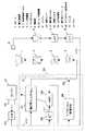
従来のこのような技術としては、能動型騒音低減装置からの出力信号及びこの信号を空間に放射するスピーカの挙動から得られた信号を用いて能動型騒音低減装置の異常を検出する方法が知られている(例えば特許文献1参照)。図6は、前記特許文献1に記載された従来の能動型騒音低減装置の構成を示すものである。
【0003】
図6に示した能動型騒音低減装置は、騒音源であるエンジンからマフラを介して放出される騒音を打ち消すように動作する。コントローラ部9で形成された騒音をキャンセルするためのキャンセル信号は、D/A変換器4(Digital to Analog Converter)でディジタル信号からアナログ信号に変換され、さらに低域通過フィルタ3で不要高調波成分を除去された後、電力増幅器2に入力される。この電力増幅器2で電力増幅されたキャンセル信号は、スピーカ1によりキャンセル音として空間に放射され、マフラからの騒音との干渉により騒音をキャンセルする。キャンセルした結果である残留音は、マイクロフォン5により電気信号へ変換され、誤差信号として増幅器6に入力される。この増幅器6で増幅された誤差信号は、低域通過フィルタ7で不要高調波成分が除去された後、A/D変換器8(Analog to Digital Converter)に入力される。このA/D変換器8は、初期に設定された電圧値(例えば、低域通過フィルタ7の直流バイアス電圧)を基準値(0)として、入力されたアナログ信号を正及び負のディジタル信号に変換する。A/D変換器8で量子化され、アナログ信号からディジタル信号に変換された誤差信号eは、キャンセル信号を形成するためにコントローラ部9に入力される。コントローラ部9にはディジタル信号を処理する離散演算処理装置であるDSP(Digital Signal Processor)が使用されている。このDSPには主処理を行う適応型フィルタが設けられており、エンジンの回転パルスから生じる騒音の模擬的信号(参照信号)と誤差信号とにより適応演算的にキャンセル信号を形成することで、騒音源から発生する定常的な低周波騒音を低減できる。
【0004】
この能動型騒音低減装置は、自身の異常を検出するために異常検出部13を設けている。この異常検出部13には、能動型騒音低減装置の各部から出力された異常検出信号が入力される。異常検出部13はこれら異常検出信号を処理し、異常と判断した場合には、コントローラ部9のリセット信号、キャンセル音のレベルダウン信号、コントローラ部9自体の電源スイッチ14をオフにする信号を発生して、キャンセル信号を形成する機能を停止させる。
【0005】
異常検出部13が能動型騒音低減装置自体の異常を検出するための異常検出信号について、以下に詳細を述べる。図6において▲1▼で示した異常検出信号は、スピーカ1のダイアフラムの大振動により異常を検出するものである。スピーカ1のダイアフラムの裏側にスイッチを設け、ダイアフラムの大振幅によりこのスイッチをオン、オフさせた信号と基準信号とを比較することで異常を検出する。即ち、スピーカ1のダイアフラムが大振幅をしているということは、能動型騒音低減装置が過大なレベルを出力していることになるため、異常を検出できることとなる。
【0006】
図6において▲2▼で示した異常検出信号は、スピーカ1のボイスコイルの異常温度上昇により異常を検出するものである。スピーカ1のボイスコイル付近に熱電対を設け、熱起電力を電圧に変換した信号と基準電圧を比較することで異常を検出する。即ち、ボイスコイルの温度が異常な上昇をするということは、過大な出力信号電流が流れていることになるため、異常を検出できることとなる。
【0007】
図6において▲3▼で示した異常検出信号は、電力増幅器2からスピーカ1への出力電流による磁束密度変化により異常を検出するものである。スピーカ1へ出力電流が流れるケーブルに磁束密度検出器を設け、この磁束密度検出器からの出力信号を整流平滑した信号と基準電圧とを比較することで異常を検出する。即ち、磁束密度の変化を検出するということは、スピーカ1に出力電流が大きく周期が小さい異常電流が流れていることになるため、異常を検出できることとなる。
【0008】
図6において▲4▼で示した異常検出信号は、電力増幅器2へ入力されるキャンセル信号のレベルにより異常を検出するものである。電力増幅器2へ入力される低域通過フィルタ3からの出力信号を分岐し、整流平滑した信号と基準電圧とを比較することで異常を検出する。即ち、キャンセル信号のレベルが異常値となるということは、予め予測した最大値を超えているということになるため、異常を検出できることとなる。
【0009】
図6において▲5▼で示した異常検出信号は、電力増幅器2へ入力される信号からキャンセル信号を取り除いた信号のレベルにより異常を検出するものである。電力増幅器2へ入力される低域通過フィルタ3からの出力信号を分岐し、この信号をキャンセル信号の周波数帯域を除去する帯域消去フィルタを通過させて帯域消去信号を得る。この帯域消去信号を整流平滑した信号と基準電圧とを比較することで異常を検出する。即ち、帯域消去信号のレベルが異常値となるということは、キャンセル信号以外の周波数成分が含まれているということになるため、異常を検出できることとなる。
【0010】
図6において▲6▼で示した異常検出信号は、電力増幅器2へ入力される信号と低域通過フィルタ7の出力信号との位相比較により異常を検出するものである。電力増幅器2へ入力される低域通過フィルタ3からの出力信号を分岐した信号の位相と、低域通過フィルタ7の出力信号の位相を比較する位相比較器からの出力信号のレベルにより異常を検出する。即ち、位相比較器からの出力信号のレベルが異常値となるということは、同周波数且つ逆位相であるべき信号の関係が崩れているということになるため、異常を検出できることとなる。
【0011】
【特許文献1】
特開平6−250671号公報(5頁、第1図)
【0012】
【発明が解決しようとする課題】
しかしながら、上記の従来技術に係る能動型騒音低減装置では、スピーカ1や電力増幅器2等の機器が既に動作した結果、或いは、既に信号として出力されてしまったキャンセル信号の値に基づいて異常を判断した後にコントローラ部9でのキャンセル信号形成機能を停止させている。従って、実際に異常が起こった直後から異常検出部13が異常を判断するまでの間、異常音としては既に空間に放射し続けられているため、暫くの間ユーザはこの異常音を聞いてしまう恐れがあるという問題を有していた。特に、コントローラ部9に入力されるマイクロフォン5からの誤差信号eが異常となった場合、コントローラ部9での適応演算も異常となり、正常な騒音低減効果が得られないだけでなく、最悪の場合、適応型フィルタの演算結果が収束せず発散に至る可能性が非常に高い。この場合、異常検出部13が異常を判断するまでの間、コントローラ部9が出し得る最大レベルに近い信号が出力され続けるため、ユーザに多大な不快感を与えてしまうという問題を有していた。
【0013】
本発明は上記従来の課題を解決するもので、適応演算に使用されるマイクロフォンからの出力信号が異常となった場合でも、適応型コントローラからの異常音をユーザが聞くことのない能動型騒音低減装置を提供することを目的とするものである。
【0014】
【課題を解決するための手段】
上記目的を達成するために、本発明は以下の構成を有する。
【0015】
本発明の請求項1に記載の発明は、車室内に発生する騒音に対し、この騒音を能動的に打ち消す2次騒音の振幅と位相を演算により求める適応型コントローラと、前記2次騒音を車室内に発生する2次騒音発生手段と、前記2次騒音と前記騒音との干渉による残留音を検出するマイクロフォンと、前記マイクロフォンから送信された信号を所定の基準電圧で0となるようなA/D変換を施すA/D変換器とを有する能動型騒音低減装置において、前記A/D変換器から適応型コントローラに送信される信号が分岐して入力されるマイクロフォン監視手段と、適応型コントローラから2次騒音発生手段に送信される信号のオンオフ動作をマイクロフォン監視手段により制御されるスイッチとを設け、マイクロフォン監視手段は前記A/D変換器から送信された信号が所定時間継続して正及び負の同一符号の時、前記スイッチをオフ動作にして2次騒音の発生を停止させるように構成されていることを特徴とする。本発明によれば、マイクロフォンからの出力信号が交流的に変化せず、直流的になっているという異常を検出して、それに伴い2次騒音の発生を停止させることができるという作用効果が得られる。
【0016】
本発明の請求項2に記載の発明は、車室内に発生する騒音に対し、この騒音を能動的に打ち消す2次騒音の振幅と位相を演算により求める適応型コントローラと、前記2次騒音を車室内に発生する2次騒音発生手段と、前記2次騒音と前記騒音との干渉による残留音を検出するマイクロフォンと、前記マイクロフォンから送信された信号を所定の基準電圧で0となるようなA/D変換を施すA/D変換器とを有する能動型騒音低減装置において、前記A/D変換器から適応型コントローラに送信される信号が分岐して入力されるマイクロフォン監視手段と、適応型コントローラから2次騒音発生手段に送信される信号のオンオフ動作をマイクロフォン監視手段により制御されるスイッチとを設け、マイクロフォン監視手段は前記A/D変換器から送信された信号の符号が正となる時間と負となる時間との比率が所定値以上になった時、前記スイッチをオフ動作にして2次騒音の発生を停止させるように構成されていることを特徴とする。本発明によれば、マイクロフォンからの出力信号のバイアスが0から変化し、直流オフセットを生じているという異常を検出して、それに伴い2次騒音の発生を停止させることができるという作用効果が得られる。
【0017】
【発明の実施の形態】
(実施の形態1)
以下、実施の形態1を用いて、本発明の請求項1に記載の発明について説明する。なお、従来技術において示した従来の能動型騒音低減装置と同一の構成要素には同一の符号を付して説明の省略を行う。また、本発明を例えば車両等に搭載し、車両走行時のエンジン振動に起因して車室内に発生した騒音を低減させる場合について説明する。
【0018】
図1は、本実施の形態1における能動型騒音低減装置の構成をブロック図として示したものである。図1において、エンジン21は課題となる騒音を発生させる騒音源であり、この能動型騒音低減装置はエンジン21の振動に起因して車室内に放射される騒音を低減する2次騒音を発生させる。
【0019】
エンジン21の振動による騒音発生状態と相関の高い信号を得るため、エンジン21の近傍に振動センサ22を設けてエンジン21の振動を検出する。振動センサ22からのアナログ出力信号は、A/D変換器23で量子化され、ディジタル信号に変換された後、離散演算処理装置であるDSP30内に構成された適応型コントローラ27に参照信号xとして入力される。
【0020】
適応型コントローラ27は、更新可能なN個のタップを有するFIR(Finite Impulse Response)型の適応型フィルタ24(そのフィルタ係数をWNとする)と、D/A変換器4の出力からA/D変換器8の入力までの信号伝達における遅延特性等を補償するFIR型の補償フィルタ25(そのフィルタ係数をC^とする)と、この補償フィルタ25によりフィルタリングされた参照信号r及び騒音と2次騒音の干渉による残留音をマイクロフォン5が検出した信号のディジタル信号である誤差信号eによりLMS(Least Mean Square)アルゴリズムに基づいて適応型フィルタ24のフィルタ係数WNを誤差信号eが最小値となるように更新するLMS処理部26とにより構成される。
【0021】
この適応型コントローラ27に入力された参照信号xは、適応型フィルタ24のフィルタ係数WNと畳み込み演算され、課題となる騒音を打ち消す2次騒音として形成された後、D/A変換器4と低域通過フィルタ3を介して、2次騒音発生手段としての電力増幅器2とスピーカ1より車室内に放射される。なお、エンジン21の振動による騒音発生状態と相関の高い信号には、TDCセンサ(上死点センサ)の出力信号やタコパルス等を用いることもできる。
【0022】
上記したように、この能動型騒音低減装置は、適応型コントローラ27に入力されるマイクロフォン5からの出力信号である誤差信号eを最小にすべく適応型フィルタ24のフィルタ係数WNを更新させて2次騒音を形成している。よって、誤差信号eは、この能動型騒音低減装置を正常に機能させるために非常に重要な信号であることが分かる。マイクロフォン5や増幅器6等による何らかの原因で誤差信号eが異常となった場合、正常な騒音低減効果が得られないだけでなく、最悪の場合、適応型フィルタ24のフィルタ係数WNが発散して、スピーカ1から異常音を発生する可能性が高い。よって、誤差信号eが異常となった場合、即座にそれを検出して、適応型フィルタ24のフィルタ係数WNが異常値となり発散に至る前に2次騒音の発生を停止させる必要がある。
【0023】
本実施の形態1では、上記を実現させるために、DSP30内にマイクロフォン監視手段28と、このマイクロフォン監視手段28によりオン、オフが制御されるスイッチ29を設ける。マイクロフォン監視手段28には適応型コントローラ27に入力される誤差信号eが分岐して入力され、その符号の変化により信号が交流的に変化しているか否かが常に監視される。マイクロフォン監視手段28は、入力された誤差信号eの符号が設定した時間継続して同一である場合に、誤差信号eが交流的に変化しておらず直流的になっているという異常を検出し、即座にスイッチ29を遮断することで、異常な誤差信号eによる適応演算で形成された2次騒音がスピーカ1より放射されることを防止する。これらマイクロフォン監視手段28とスイッチ29は、DSP30内にソフトウェアとして構成される。
【0024】
マイクロフォン監視手段28が誤差信号eの符号の変化を監視する様子を図2及び図3を用いて以下に説明する。
【0025】
図2は、この能動型騒音低減装置が起動し、A/D変換器8が動作を開始した時刻を0(n=0)として、そこからサンプリング周期Ts(sec)で量子化された誤差信号eの系列{e(n)}の一例を表したものである。マイクロフォン監視手段28は、誤差信号eの値が更新される毎、即ちサンプリング周期Ts(sec)毎に、現在の誤差信号eの符号と前回サンプリング時の誤差信号eの符号が同一か否かの判断を行う。マイクロフォン監視手段28の内部にはカウンタ(ダウンカウンタ)が設けられており、誤差信号eの符号が同一となる時間を計測する。このカウンタは、n=0において初期値Kがセットされ初期化される。以降、n=1,2,3…の各サンプリング時刻において、現在の誤差信号eの符号と前回サンプリング時の誤差信号eの符号が同一である場合にはカウンタの値が1つ減算され(デクリメント)、現在の誤差信号eの符号と前回サンプリング時の誤差信号eの符号が異なる場合には再度カウンタに初期値Kがセット(初期化)される。
【0026】
ここで、このカウンタの初期値Kは、次のようにして求められる。即ち、誤差信号eの符号がTbrk(sec)の間継続して同一の場合にマイクロフォン監視手段28が異常を検出するように設定するならば、K=Tbrk/Ts=Tbrk×fs(fsはサンプリング周波数)となる。仮に誤差信号eに何らかの原因で異常が発生し、以降継続して同一符号となる場合、カウンタはデクリメントされ続けられる。その結果、最終的にカウンタは0に至ることになるが、これは即ち誤差信号eがTbrk(sec)の間継続して同一符号となることと等価である。従って、マイクロフォン監視手段28はカウンタが0であるか否かをサンプリング周期毎に判断することで、誤差信号eが直流的になっているという異常を検出することができる。
【0027】
図2の例では、誤差信号eの符号が12×Ts(sec)の間継続して同一の場合にマイクロフォン監視手段28が異常を検出するように設定している。つまり、Tbrk=12×Ts(sec)であるので、カウンタの初期値Kは、K=12となる。まず、n=0において、マイクロフォン監視手段28に誤差信号e(0)の符号は負であることが記録されるとともに、カウンタが初期化される。n=1において、誤差信号e(1)の符号はe(0)の符号と同じく負であるため、カウンタがデクリメントされる。その結果、カウンタは11となるが、0ではないので誤差信号eは正常であると判断される。以降同様に、n=2,3においても誤差信号eの符号は負であるのでカウンタがデクリメントされるが、その値は9までしか至らないので、この間の誤差信号eは正常であると判断される。
【0028】
さて、n=4において、誤差信号e(4)の符号は正に変化しているため、カウンタは再び初期化される。以降同様に、n=5,6,7,8においても誤差信号eの符号は正であるのでカウンタがデクリメントされるが、その値は8までしか至らないので、この間の誤差信号eは正常である判断される。さらに、n=9において、誤差信号e(9)の符号は再び負に変化しているため、カウンタも再度初期化される。以降同様にn=10,11,…21,22においても誤差信号eの符号は負であるのでカウンタがデクリメントされるが、n=21においてカウンタは遂に0に至る。この時、マイクロフォン検出手段28は、誤差信号eがn=9からTbrk(sec)の間継続して同一符号であることを察知し、直流的になっているという異常を検出する。
【0029】
図3は、マイクロフォン監視手段28のサンプリング周期毎の動作を示すフローチャートである。まず、ステップs1で現在の誤差信号eの符号が判別される。現在の誤差信号eの符号が負の場合、ステップs2で前回サンプリング時の誤差信号eの符号も負かどうかの判別がされる。前回サンプリング時の誤差信号eの符号も負の場合、誤差信号eの符号は連続して負であるため、ステップs3でカウンタをデクリメントする。前回サンプリング時の誤差信号eの符号が正の場合、誤差信号eの符号は正から負へ変化したことになるため、ステップs3でカウンタを初期化する。
【0030】
そして、次回サンプリング時に使用するために、ステップs5で現在の誤差信号eの符号が負であったことを記録する。同様に、ステップs1で判別された現在の誤差信号eの符号が正の場合、ステップs6で前回サンプリング時の誤差信号eの符号も正かどうかの判別がされる。前回サンプリング時の誤差信号eの符号も正の場合、誤差信号eの符号は連続して正であるため、ステップs7でカウンタをデクリメントする。前回サンプリング時の誤差信号eの符号が負の場合、誤差信号eの符号は負から正へ変化したことになるため、ステップs8でカウンタを初期化する。そして、次回サンプリング時に使用するために、ステップs9で現在の誤差信号eの符号が正であったことを記録する。
【0031】
さて、ステップs3,s4,s7,s8で変化したカウンタが0になったか否かステップs10で判断される。カウンタが0でない場合、ステップs12と判断される。カウンタが0の場合、誤差信号eの符号がTbrk(sec)の間継続して同一であることになるのでステップs11で異常が検出され、マイクロフォン監視手段28はスイッチ29を遮断する。
【0032】
この実施の形態1では、車両走行時のエンジン振動に起因して車室内に発生した騒音を消音対象としている。一般に、このような騒音のスペクトルは比較的低い周波数に集中しており、車室内で乗員が特に不快に感じるのは100(Hz)以下の帯域となることが多い。このような低い周波数を制御するには、適応型コントローラ27での演算周期、即ちサンプリング周期Ts(sec)は比較的長くて良く、一般的にサンプリング周波数fsは、fs=3(kHz)程度に設定される。マイクロフォン5の周辺には、課題となる騒音と、スピーカ1からの2次騒音の他に、ロードノイズ、風切り音、車室内で再生される音楽等、外乱も含め様々な周波数の音響信号が常に存在するために、正常ならば誤差信号eは交流的に変化する。よって、誤差信号eが交流的に変化せず直流的になっているという異常を検出するための時間Tbrkは、Tbrk=1(sec)程度に設定すれば充分である。この場合、カウンタの初期値Kは、K=3000となる。
【0033】
このように外乱音が常に存在する車室内の騒音を安定的に低減するには、LMS制御部26の適応収束係数値を小さく設定する必要があるため、比較的ゆっくりとした適応演算が行われる。従って、誤差信号eに異常が発生した場合、Tbrk=1(sec)程度の設定であっても、適応型フィルタ24が発散に至る前に充分余裕を持ってスイッチ29を遮断することができ、乗員が発散による異常音を聞くことを防止することができる。
【0034】
以上のように、本実施の形態1に示す能動型騒音低減装置は、適応演算に使用されるマイクロフォンからの誤差信号の符号が設定した時間継続して同一となる場合、この誤差信号が交流的に変化せず直流的になっているという異常を検出し、この時に2次騒音の発生を停止させることで、適応型コントローラからの異常な出力音をユーザが聞くことを防止することができるという効果を奏する。
【0035】
(実施の形態2)
以下、実施の形態2を用いて、本発明の請求項2に記載の発明について説明する。本実施の形態2は図1に示した上記実施の形態1と同じ構成からなり、マイクロフォン監視手段28における異常検出のアルゴリズムのみが異なる。本実施の形態2では、マイクロフォン監視手段28に入力された誤差信号eの符号が正となる時間と負となる時間の比率が設定した値以上である場合に、誤差信号eのバイアスが0より変化して直流オフセットを生じているという異常を検出し、即座にスイッチ29を遮断することで、異常な誤差信号eによる適応演算で形成された2次騒音がスピーカ1より放射されることを防止する構成とする。
【0036】
マイクロフォン監視手段28が誤差信号eの符号が正となる時間と負となる時間の比率を監視する様子を図4及び図5を用いて以下に説明する。
【0037】
図4は、この能動型騒音低減装置が起動し、A/D変換器8が動作を開始した時刻を0(n=0)として、そこからサンプリング周期Ts(sec)で量子化された誤差信号eの系列{e(n)}の一例を表したものである。マイクロフォン監視手段28は、内部にカウンタ(アップカウンタ)が設けられており、誤差信号eの符号が変化した時点から、次に変化するまでの時間を計測する。このカウンタは、n=0において初期値0がセット(ゼロクリア)され、以降、n=1,2,3…の各サンプリング時刻毎の最初にカウンタの値が1つ加算(インクリメント)される。
【0038】
さて、マイクロフォン監視手段28は、現在の誤差信号eの符号と前回サンプリング時の誤差信号eの符号とを比較し、これらが異なる場合に、以下の3つの処理を実行する。まず、現在のカウンタ値と前回保存したカウンタ値との比を計算し、最も近い過去に誤差信号eの符号が正であった時間と負であった時間との比率を求める。次に、次回の比率計算の時に使用するために、現在のカウンタ値を保存しておく。最後に、誤差信号eが今回変化してなった符号を継続する時間を計測するために、カウンタをゼロクリアしておく。
【0039】
ここで、求めるべき比率は、次のようにして計算するものとする。即ち、現在のカウンタ値と前回保存したカウンタ値を比較し、値の小さい方を基準として比率を計算するものとする。各サンプリング時刻毎の最後に、マイクロフォン監視手段28は、上記のように求めた比率と異常検出のために設定した値との比較を行い、誤差信号eが正常か否かの判断を行う。さて、この際に注意すべきことがある。それは、n=0から誤差信号eの符号が最初に変化するまでの時間(t1)を計測したカウンタ値を使用して求められた比率は無効だということである。これは、A/D変換器8の動作開始時刻であるn=0より以前にも、誤差信号e(0)の符号と同じ符号を持つ誤差信号が存在し得ると考えられるためである。
【0040】
以上のことを考慮すると、マイクロフォン監視手段28は、最初の比率が計算される以前、もしくは、比率の計算にt1を計測したカウンタ値が使用されている間、誤差信号eの異常検出を正確に行えないこととなる。言い換えれば、比率の計算が3回未満の間、マイクロフォン監視手段28は誤差信号eの異常を正確に検出できない。よって、この間の誤差信号eは常に正常であると判断するものとする。そして、比率の計算が3回目以降になった時点から、求められた比率の値を異常検出のために使用していく。仮に誤差信号eに何らかの原因で異常が発生し、この比率が設定値以上となる場合、誤差信号eが正の符号となる時間と負の符号となる時間が著しく異なっていることとなるため、直流オフセットを生じているという異常を検出することができる。
【0041】
図4の例では、誤差信号eの符号が正となる時間と負となる時間の比率が7以上の場合にマイクロフォン監視手段28が異常を検出するように設定している。まず、n=0において、マイクロフォン監視手段28に誤差信号e(0)の符号は負であることが記録されるとともに、カウンタがゼロクリアされる。n=1において、このカウンタをインクリメントするとともに、現在の誤差信号e(1)の符号と前回サンプリング時の誤差信号e(0)の符号を比較する。ここで、e(1)の符号とe(0)の符号は同じ負であり、最初の比率が計算される以前であるので、誤差信号eは正常であると判断される。以降同様に、n=2,3においても誤差信号eの符号が変化せず、最初の比率が計算される以前であるので、この間の誤差信号eは正常である判断される。
【0042】
さて、n=4において、誤差信号e(4)の符号は、負から正へ1回目の変化を生じている。この時、サンプリング時刻の最初にインクリメントされた現在のカウンタは4となっており、t1=4×Ts(sec)であることを表している。誤差信号eの符号が変化したので、まず上記現在のカウンタ値を用いて比率が計算される。現在のカウンタ値の4と前回のカウンタ値(ここでは、前回のカウンタ値として適当な初期値:2を用意する)を比較し、値の小さい方(この場合、前回のカウンタ値である2)を基準とした比率が計算される。即ち、4/2=2が求められた比率である。しかし、上述のようにこの値は無効であり、異常検出のためには使用されない。
【0043】
次に、現在のカウンタ値を保存して、次回の比率計算に備える。さらに、以降で誤差信号eの符号が正となる時間を計測するために、カウンタをゼロクリアしておく。今回、1回目の比率が計算されたものの、その値は無視されるので誤差信号eは正常であると判断される。以降、n=5,6,7,8においても誤差信号eの符号は正のまま変化せず、比率は計算されないので、この間の誤差信号eは正常である判断される。次に誤差信号eが符号の変化を生じるのは、n=9の時である。ここで、誤差信号e(9)の符号は、正から負へ2回目の変化を生じている。この時、サンプリング時刻の最初にインクリメントされた現在のカウンタは5となっており、t2=5×Ts(sec)であることを表している。誤差信号eの符号が変化したので、まず上記現在のカウンタ値を用いて比率が計算される。現在のカウンタ値の5と前回のカウンタ値の4を比較し、値の小さい方(この場合、前回のカウンタ値である4)を基準とした比率が計算される。即ち、5/4=1.25が求められた比率である。しかし、上述のようにこの値は無効であり、異常検出のためには使用されない。
【0044】
次に、現在のカウンタ値を保存して、次回の比率計算に備える。さらに、以降で誤差信号eの符号が負となる時間を計測するために、カウンタをゼロクリアしておく。今回、2回目の比率が計算されたものの、その値は無視されるので誤差信号eは正常であると判断される。以降、n=10,11,…15,16においても誤差信号eの符号は負のまま変化せず、比率は計算されないので、この間の誤差信号eは正常である判断される。次に誤差信号eが符号の変化を生じるのは、n=17の時である。ここで、誤差信号e(17)の符号は、負から正へ3回目の変化を生じている。この時、サンプリング時刻の最初にインクリメントされた現在のカウンタは8となっており、t3=8×Ts(sec)であることを表している。誤差信号eの符号が変化したので、まず上記現在のカウンタ値を用いて比率が計算される。現在のカウンタ値の8と前回のカウンタ値の5を比較し、値の小さい方(この場合、前回のカウンタ値である5)を基準とした比率が計算される。即ち、8/5=1.6が求められた比率である。
【0045】
次に、現在のカウンタ値を保存して、次回の比率計算に備える。さらに、以降で誤差信号eの符号が正となる時間を計測するために、カウンタをゼロクリアしておく。今回で比率の計算は3回目となるため、求められた比率1.6は誤差信号eが正常か否かを判断するために使用される。以降、求められた比率は全て誤差信号eの異常を検出するための有効な値となる。今回求められた比率1.6は、異常を検出するための設定値である7より小さい。よって、マイクロフォン監視手段28は、誤差信号eは正常であると判断する。
【0046】
次に誤差信号eが符号の変化を生じるのは、n=18の時である。ここで、誤差信号e(18)の符号は、正から負へ4回目の変化を生じている。この時、サンプリング時刻の最初にインクリメントされた現在のカウンタは1となっており、t4=1×Ts(sec)であることを表している。誤差信号eの符号が変化したので、まず上記現在のカウンタ値を用いて比率が計算される。現在のカウンタ値の1と前回のカウンタ値の8を比較し、値の小さい方(この場合、現在のカウンタ値である1)を基準とした比率が計算される。即ち、8/1=8が求められた比率である。
【0047】
次に、現在のカウンタ値を保存して、次回の比率計算に備える。さらに、以降で誤差信号eの符号が正となる時間を計測するために、カウンタをゼロクリアしておく。今回求められた比率8は、異常を検出するための設定値である7より大きい。この時、マイクロフォン監視手段28は、誤差信号eの符号が正となる時間と負となる時間が著しく差があることを察知し、直流オフセットが生じているという異常を検出する。
【0048】
図5は、マイクロフォン監視手段28のサンプリング周期毎の動作を示すフローチャートである。まず、ステップs21でカウンタの値がインクリメントされる。次に、ステップs22で現在の誤差信号eの符号が判別される。現在の誤差信号eの符号が負の場合、ステップs23で前回サンプリング時の誤差信号eの符号も負かどうかの判別がされる。前回サンプリング時の誤差信号eの符号も負の場合、誤差信号eの符号は連続して負であるため、比率計算等の処理は実行しない。前回サンプリング時の誤差信号eの符号が正の場合、誤差信号eの符号は正から負へ変化したことになるため、ステップs24で現在のカウンタ値と前回保存したカウンタ値の比率を計算する。
【0049】
次いで、次回の比率計算のためにステップs25で現在のカウンタ値を保存しておく。さらに、ステップs26で時間計測のためにカウンタをゼロクリアしておく。そして、次回サンプリング時に使用するために、ステップs27で現在の誤差信号eの符号が負であったことを記録する。同様に、ステップs22で判別された現在の誤差信号eの符号が正の場合、ステップs28で前回サンプリング時の誤差信号eの符号も正かどうかの判別がされる。前回サンプリング時の誤差信号eの符号も正の場合、誤差信号eの符号は連続して正であるため、比率計算等の処理は実行しない。前回サンプリング時の誤差信号eの符号が負の場合、誤差信号eの符号は負から正へ変化したことになるため、ステップs29で現在のカウンタ値と前回保存したカウンタ値の比率を計算する。
【0050】
次いで、次回の比率計算のためにステップs30で現在のカウンタ値を保存しておく。さらに、ステップs31で時間計測のためにカウンタをゼロクリアしておく。そして、次回サンプリング時に使用するために、ステップs32で現在の誤差信号eの符号が正であったことを記録する。さて、ステップs24,s29で比率を計算するのは3回目以上か否かステップs33で判断される。3回目未満の場合、ステップs37で正常と判断される。3回目以上の場合、求められた比率が異常検出のための設定値以上か否かステップs34で判断される。求められた比率が設定値未満の場合、ステップs36で正常と判断される。求められた比率が設定値以上の場合、ステップs35で異常が検出され、マイクロフォン監視手段28はスイッチ29を遮断する。
【0051】
以上のように、本実施の形態2に示す能動型騒音低減装置は、適応演算に使用されるマイクロフォン5からの誤差信号の符号が正となる時間と負となる時間をそれぞれ計測して求めた比率が設定値以上となる場合、この誤差信号が直流オフセットを生じているという異常を検出し、この時に2次騒音の発生を停止させることで、適応型コントローラ27からの異常な出力音をユーザが聞くことを防止することができるという効果を奏する。
【0052】
【発明の効果】
以上の説明のように本発明によれば、適応演算に使用されるマイクロフォンからの誤差信号を監視し、符号が一定時間継続して同一となる場合に誤差信号が直流的になっているという異常を、また、符号が正となる時間と負となる時間が著しく異なる場合に誤差信号が直流オフセットを生じているという異常をそれぞれ検出して、適応型フィルタが発散に至る前に即座に2次騒音の発生を停止することで、適応型コントローラからの異常な出力音をユーザが聞くことを未然に防止することができるという効果を奏するものである。
【図面の簡単な説明】
【図1】本発明の実施の形態1に係る能動型騒音低減装置の構成を示すブロック図
【図2】同実施の形態1に係る誤差信号の系列を表す図
【図3】同実施の形態1に係るフローチャート
【図4】同実施の形態2に係る誤差信号の系列を表す図
【図5】同実施の形態2に係るフローチャート
【図6】従来の能動騒音低減装置の構成を示すブロック図
【符号の説明】
1 スピーカ(2次騒音発生手段)
2 電力増幅器(2次騒音発生手段)
3、7 低域通過フィルタ
4 D/A変換器
5 マイクロフォン
6 増幅器
8、23 A/D変換器
9 コントローラ部
13 異常検出部
21 エンジン
22 振動センサ
24 適応型フィルタ
25 補償フィルタ
26 LMS処理部
27 適応型コントローラ
28 マイクロフォン監視手段
29 スイッチ
30 DSP[0001]
BACKGROUND OF THE INVENTION
The present invention relates to an active noise reduction device for reducing noise by causing signals having opposite phases and equal amplitudes to interfere with unpleasant noise generated in the passenger compartment as the engine rotates and the vehicle travels. In particular, an object of the present invention is to prevent abnormal noise from being generated due to abnormal noise reduction operation due to an abnormality in an output signal from a microphone that detects a noise reduction error.
[0002]
[Prior art]
As such a conventional technique, there is known a method for detecting an abnormality of an active noise reduction apparatus using an output signal from the active noise reduction apparatus and a signal obtained from the behavior of a speaker that radiates this signal to space. (See, for example, Patent Document 1). FIG. 6 shows a configuration of a conventional active noise reduction apparatus described in
[0003]
The active noise reduction apparatus shown in FIG. 6 operates so as to cancel noise emitted from the engine that is a noise source through the muffler. A cancel signal for canceling noise generated by the controller unit 9 is converted from a digital signal to an analog signal by a D / A converter 4 (Digital to Analog Converter), and further, an unnecessary harmonic component is converted by a low-
[0004]
This active noise reduction apparatus is provided with an
[0005]
Details of the abnormality detection signal for the
[0006]
The abnormality detection signal indicated by (2) in FIG. 6 detects an abnormality due to an abnormal temperature rise in the voice coil of the
[0007]
The abnormality detection signal indicated by (3) in FIG. 6 detects an abnormality based on a change in magnetic flux density due to an output current from the
[0008]
The abnormality detection signal indicated by (4) in FIG. 6 detects an abnormality based on the level of the cancel signal input to the
[0009]
The abnormality detection signal indicated by (5) in FIG. 6 detects an abnormality based on the level of the signal obtained by removing the cancel signal from the signal input to the
[0010]
The abnormality detection signal indicated by (6) in FIG. 6 detects an abnormality by phase comparison between the signal input to the
[0011]
[Patent Document 1]
Japanese Patent Laid-Open No. 6-250671 (
[0012]
[Problems to be solved by the invention]
However, in the active noise reduction device according to the above-described prior art, the abnormality is determined based on the result of the operation of the devices such as the
[0013]
The present invention solves the above-mentioned conventional problems, and even if the output signal from the microphone used for adaptive calculation becomes abnormal, the active noise reduction without the user hearing the abnormal sound from the adaptive controller The object is to provide an apparatus.
[0014]
[Means for Solving the Problems]
In order to achieve the above object, the present invention has the following configuration.
[0015]
According to the first aspect of the present invention, there is provided an adaptive controller that obtains the amplitude and phase of secondary noise that actively cancels out noise generated in the passenger compartment by calculation, and the secondary noise is detected in the vehicle. Secondary noise generating means generated in the room, and a microphone for detecting residual sound due to interference between the secondary noise and the noise;An A / D converter that performs A / D conversion so that the signal transmitted from the microphone becomes 0 at a predetermined reference voltage; In an active noise reduction device havingA / D converter Provided with a microphone monitoring means for branching and inputting a signal to be transmitted from the adaptive controller to the adaptive controller, and a switch for controlling the on / off operation of the signal transmitted from the adaptive controller to the secondary noise generating means by the microphone monitoring means. The microphone monitoring means is the aforementionedA / D converter When the signal transmitted from the terminal has the same positive and negative signs for a predetermined time, the switch is turned off to stop the generation of secondary noise. According to the present invention, it is possible to detect an abnormality that the output signal from the microphone does not change in an alternating current but is in a direct current, and to stop the generation of secondary noise accordingly. It is done.
[0016]
According to a second aspect of the present invention, there is provided an adaptive controller for calculating the amplitude and phase of secondary noise that actively cancels out noise generated in a passenger compartment, and calculating the secondary noise in a vehicle. Secondary noise generating means generated in the room, and a microphone for detecting residual sound due to interference between the secondary noise and the noise;An A / D converter that performs A / D conversion so that the signal transmitted from the microphone becomes 0 at a predetermined reference voltage; In an active noise reduction device havingA / D converter Provided with a microphone monitoring means for branching and inputting a signal to be transmitted from the adaptive controller to the adaptive controller, and a switch for controlling the on / off operation of the signal transmitted from the adaptive controller to the secondary noise generating means by the microphone monitoring means. The microphone monitoring means is the aforementionedA / D converter When the ratio between the time when the sign of the signal transmitted from the signal becomes positive and the time when it becomes negative exceeds a predetermined value, the switch is turned off to stop the generation of secondary noise. It is characterized by that. According to the present invention, it is possible to detect an abnormality that the bias of the output signal from the microphone changes from 0 and causes a DC offset, and to stop the generation of secondary noise accordingly. It is done.
[0017]
DETAILED DESCRIPTION OF THE INVENTION
(Embodiment 1)
Hereinafter, the first aspect of the present invention will be described using the first embodiment. In addition, the same code | symbol is attached | subjected to the component same as the conventional active noise reduction apparatus shown in the prior art, and description is abbreviate | omitted. Further, a case will be described in which the present invention is mounted on, for example, a vehicle or the like and noise generated in the passenger compartment due to engine vibration during vehicle traveling is reduced.
[0018]
FIG. 1 is a block diagram showing the configuration of the active noise reduction apparatus according to the first embodiment. In FIG. 1, an
[0019]
In order to obtain a signal highly correlated with the noise generation state due to the vibration of the
[0020]
The
[0021]
The reference signal x input to the
[0022]
As described above, this active noise reduction apparatus has the filter coefficient W of the
[0023]
In the first embodiment, in order to realize the above, a
[0024]
The manner in which the microphone monitoring means 28 monitors the change in the sign of the error signal e will be described below with reference to FIGS.
[0025]
FIG. 2 shows an error signal quantized at a sampling period Ts (sec) from the time when the active noise reduction apparatus is activated and the A /
[0026]
Here, the initial value K of the counter is obtained as follows. That is, the sign of the error signal e is Tbrk If the microphone monitoring means 28 is set to detect an abnormality in the same case for (sec) continuously, K = Tbrk / Ts = Tbrk Xfs (fs is a sampling frequency). If an error signal e is abnormal for some reason and continues to have the same sign, the counter continues to be decremented. As a result, the counter finally reaches 0, which means that the error signal e is Tbrk This is equivalent to continuing the same code for (sec). Therefore, the microphone monitoring means 28 can detect an abnormality that the error signal e is DC by determining whether or not the counter is 0 for each sampling period.
[0027]
In the example of FIG. 2, the microphone monitoring means 28 is set to detect an abnormality when the sign of the error signal e is the same for 12 × Ts (sec). That is, Tbrk Since = 12 × Ts (sec), the initial value K of the counter is K = 12. First, at n = 0, it is recorded in the microphone monitoring means 28 that the sign of the error signal e (0) is negative, and the counter is initialized. At n = 1, the error signal e (1) has the same negative sign as e (0), so the counter is decremented. As a result, the counter becomes 11, but since it is not 0, it is determined that the error signal e is normal. Similarly, when n = 2 and 3, since the sign of the error signal e is negative, the counter is decremented. However, since the value reaches only 9, the error signal e during this period is determined to be normal. The
[0028]
Now, at n = 4, because the sign of the error signal e (4) has changed positively, the counter is initialized again. Similarly, in the case of n = 5, 6, 7 and 8, since the sign of the error signal e is positive, the counter is decremented. However, since the value reaches only 8, the error signal e during this period is normal. It is judged. Further, since the sign of the error signal e (9) changes to negative again at n = 9, the counter is initialized again. Similarly, at n = 10, 11,..., 21, 22, the sign of the error signal e is negative and the counter is decremented, but at n = 21, the counter finally reaches 0. At this time, the microphone detection means 28 determines that the error signal e changes from n = 9 to Tbrk (Sec) is detected continuously for the same code, and an abnormality that is in a direct current state is detected.
[0029]
FIG. 3 is a flowchart showing the operation of the microphone monitoring means 28 for each sampling period. First, in step s1, the sign of the current error signal e is determined. If the sign of the current error signal e is negative, it is determined in step s2 whether the sign of the error signal e at the previous sampling is also negative. If the sign of the error signal e at the previous sampling is also negative, the sign of the error signal e is continuously negative, so the counter is decremented in step s3. If the sign of the error signal e at the previous sampling is positive, the sign of the error signal e has changed from positive to negative, so the counter is initialized in step s3.
[0030]
Then, in order to use it at the next sampling, it is recorded in step s5 that the sign of the current error signal e is negative. Similarly, if the sign of the current error signal e determined in step s1 is positive, it is determined in step s6 whether the sign of the error signal e at the previous sampling is also positive. If the sign of the error signal e at the previous sampling is also positive, the sign of the error signal e is continuously positive, so the counter is decremented in step s7. If the sign of the error signal e at the previous sampling is negative, the sign of the error signal e has changed from negative to positive, so the counter is initialized in step s8. Then, in order to use it at the next sampling, it is recorded in step s9 that the sign of the current error signal e is positive.
[0031]
In step s10, it is determined whether or not the counter changed in steps s3, s4, s7, and s8 has become zero. If the counter is not 0, step s12 is determined. When the counter is 0, the sign of the error signal e is Tbrk (S), the abnormality is detected in step s11, and the microphone monitoring means 28 shuts off the
[0032]
In the first embodiment, noise generated in the passenger compartment due to engine vibration during vehicle travel is targeted for muffling. In general, such a noise spectrum is concentrated at a relatively low frequency, and it is often in a band of 100 (Hz) or less that a passenger feels particularly uncomfortable in the passenger compartment. In order to control such a low frequency, the calculation cycle in the
[0033]
Thus, in order to stably reduce the noise in the passenger compartment where disturbance noise always exists, it is necessary to set the adaptive convergence coefficient value of the
[0034]
As described above, in the active noise reduction apparatus shown in the first embodiment, when the sign of the error signal from the microphone used for the adaptive calculation remains the same for a set time, the error signal is alternating. It is possible to prevent the user from listening to an abnormal output sound from the adaptive controller by detecting the abnormality that the current is DC without changing to, and stopping the generation of secondary noise at this time There is an effect.
[0035]
(Embodiment 2)
Hereinafter, the second aspect of the present invention will be described with reference to the second embodiment. The second embodiment has the same configuration as that of the first embodiment shown in FIG. 1, and only the abnormality detection algorithm in the microphone monitoring means 28 is different. In the second embodiment, when the ratio between the time when the sign of the error signal e input to the microphone monitoring means 28 is positive and the time when it is negative is equal to or greater than the set value, the bias of the error signal e is greater than zero. By detecting an abnormality that causes a DC offset by changing and immediately shutting off the
[0036]
The manner in which the microphone monitoring means 28 monitors the ratio between the time when the sign of the error signal e is positive and the time when the error signal e is negative will be described below with reference to FIGS.
[0037]
FIG. 4 shows an error signal quantized at a sampling period Ts (sec) from the time when the active noise reduction apparatus is activated and the A /
[0038]
Now, the microphone monitoring means 28 compares the sign of the current error signal e and the sign of the error signal e at the previous sampling, and executes the following three processes if they are different. First, the ratio between the current counter value and the previously stored counter value is calculated, and the ratio between the time when the sign of the error signal e was positive and the time when it was negative in the nearest past is obtained. Next, the current counter value is saved for use in the next ratio calculation. Finally, the counter is cleared to zero in order to measure the time during which the error signal e continues for the sign that has changed this time.
[0039]
Here, the ratio to be obtained is calculated as follows. That is, the current counter value is compared with the previously stored counter value, and the ratio is calculated based on the smaller value as a reference. At the end of each sampling time, the microphone monitoring means 28 compares the ratio obtained as described above with the value set for detecting an abnormality, and determines whether or not the error signal e is normal. There is something to be careful about at this time. That is, the ratio obtained using the counter value obtained by measuring the time (t1) from n = 0 to the first change of the sign of the error signal e is invalid. This is because it is considered that an error signal having the same sign as that of the error signal e (0) may exist before n = 0, which is the operation start time of the A /
[0040]
In consideration of the above, the microphone monitoring means 28 accurately detects the abnormality of the error signal e before the first ratio is calculated or while the counter value obtained by measuring t1 is used for the ratio calculation. It will not be possible. In other words, the microphone monitoring means 28 cannot accurately detect the abnormality of the error signal e while the ratio is calculated less than three times. Therefore, it is determined that the error signal e during this period is always normal. Then, from the time when the ratio calculation is performed for the third time or later, the obtained ratio value is used for abnormality detection. If an error occurs in the error signal e for some reason and this ratio is greater than or equal to the set value, the time when the error signal e becomes a positive sign and the time when it becomes a negative sign are significantly different. It is possible to detect an abnormality that causes a DC offset.
[0041]
In the example of FIG. 4, the microphone monitoring means 28 is set to detect an abnormality when the ratio of the time when the sign of the error signal e is positive and the time when it is negative is 7 or more. First, at n = 0, the microphone monitoring means 28 records that the sign of the error signal e (0) is negative, and the counter is cleared to zero. When n = 1, the counter is incremented and the sign of the current error signal e (1) is compared with the sign of the error signal e (0) at the previous sampling. Here, since the sign of e (1) and the sign of e (0) are the same negative and before the first ratio is calculated, it is determined that the error signal e is normal. Similarly, since the sign of the error signal e does not change even when n = 2 and 3, and before the first ratio is calculated, it is determined that the error signal e during this period is normal.
[0042]
Now, at n = 4, the sign of the error signal e (4) changes from negative to positive for the first time. At this time, the current counter incremented at the beginning of the sampling time is 4, indicating that t1 = 4 × Ts (sec). Since the sign of the error signal e has changed, the ratio is first calculated using the current counter value. The
[0043]
Next, the current counter value is saved to prepare for the next ratio calculation. Further, the counter is cleared to zero in order to measure the time when the sign of the error signal e is positive thereafter. Although the ratio of the first time is calculated this time, the value is ignored, so that it is determined that the error signal e is normal. Thereafter, even when n = 5, 6, 7, and 8, the sign of the error signal e remains positive and the ratio is not calculated. Therefore, it is determined that the error signal e during this period is normal. Next, the error signal e changes in sign when n = 9. Here, the sign of the error signal e (9) changes for the second time from positive to negative. At this time, the current counter incremented at the beginning of the sampling time is 5, indicating that t2 = 5 × Ts (sec). Since the sign of the error signal e has changed, the ratio is first calculated using the current counter value. The current counter value of 5 and the previous counter value of 4 are compared, and a ratio based on the smaller value (in this case, the previous counter value of 4) is calculated. That is, 5/4 = 1.25 is the obtained ratio. However, as described above, this value is invalid and is not used for abnormality detection.
[0044]
Next, the current counter value is saved to prepare for the next ratio calculation. Further, the counter is cleared to zero in order to measure the time when the sign of the error signal e is negative thereafter. Although the ratio for the second time is calculated this time, the value is ignored, so that the error signal e is determined to be normal. Thereafter, even when n = 10, 11,..., 15, 16, the sign of the error signal e remains negative and the ratio is not calculated. Therefore, it is determined that the error signal e during this period is normal. Next, the error signal e changes in sign when n = 17. Here, the sign of the error signal e (17) changes from negative to positive for the third time. At this time, the current counter incremented at the beginning of the sampling time is 8, indicating that t3 = 8 × Ts (sec). Since the sign of the error signal e has changed, the ratio is first calculated using the current counter value. The
[0045]
Next, the current counter value is saved to prepare for the next ratio calculation. Further, the counter is cleared to zero in order to measure the time when the sign of the error signal e is positive thereafter. Since the ratio is calculated for the third time this time, the obtained ratio 1.6 is used to determine whether or not the error signal e is normal. Thereafter, all the obtained ratios are effective values for detecting the abnormality of the error signal e. The ratio 1.6 obtained this time is smaller than 7, which is a set value for detecting an abnormality. Therefore, the microphone monitoring means 28 determines that the error signal e is normal.
[0046]
Next, the error signal e changes in sign when n = 18. Here, the sign of the error signal e (18) changes from positive to negative for the fourth time. At this time, the current counter incremented at the beginning of the sampling time is 1, indicating that t4 = 1 × Ts (sec). Since the sign of the error signal e has changed, the ratio is first calculated using the current counter value. The current counter value of 1 is compared with the previous counter value of 8, and the ratio based on the smaller value (in this case, the current counter value of 1) is calculated. That is, 8/1 = 8 is the obtained ratio.
[0047]
Next, the current counter value is saved to prepare for the next ratio calculation. Further, the counter is cleared to zero in order to measure the time when the sign of the error signal e is positive thereafter. The
[0048]
FIG. 5 is a flowchart showing the operation of the microphone monitoring means 28 for each sampling period. First, in step s21, the value of the counter is incremented. Next, in step s22, the sign of the current error signal e is determined. If the sign of the current error signal e is negative, it is determined in step s23 whether the sign of the error signal e at the previous sampling is also negative. When the sign of the error signal e at the previous sampling is also negative, the sign of the error signal e is continuously negative, and thus processing such as ratio calculation is not executed. If the sign of the error signal e at the previous sampling is positive, the sign of the error signal e has changed from positive to negative. Therefore, in step s24, the ratio between the current counter value and the previously stored counter value is calculated.
[0049]
Next, the current counter value is stored in step s25 for the next ratio calculation. In step s26, the counter is cleared to zero for time measurement. Then, in order to use it at the next sampling, it is recorded in step s27 that the sign of the current error signal e is negative. Similarly, if the sign of the current error signal e determined in step s22 is positive, it is determined in step s28 whether the sign of the error signal e at the previous sampling is also positive. When the sign of the error signal e at the previous sampling is also positive, the sign of the error signal e is continuously positive, and thus processing such as ratio calculation is not executed. If the sign of the error signal e at the previous sampling is negative, the sign of the error signal e has changed from negative to positive, so the ratio between the current counter value and the previously stored counter value is calculated in step s29.
[0050]
Next, the current counter value is stored in step s30 for the next ratio calculation. In step s31, the counter is cleared to zero for time measurement. Then, in order to use it at the next sampling, it is recorded in step s32 that the sign of the current error signal e is positive. In step s33, it is determined whether or not the ratio is calculated for the third time or more in steps s24 and s29. If it is less than the third time, it is determined to be normal in step s37. In the case of the third or more times, it is determined in step s34 whether or not the obtained ratio is not less than a set value for detecting an abnormality. If the obtained ratio is less than the set value, it is determined as normal in step s36. If the determined ratio is greater than or equal to the set value, an abnormality is detected in step s35, and the microphone monitoring means 28 shuts off the
[0051]
As described above, the active noise reduction apparatus shown in the second embodiment is obtained by measuring the time when the sign of the error signal from the
[0052]
【The invention's effect】
As described above, according to the present invention, the error signal from the microphone used for the adaptive calculation is monitored, and the error signal is DC when the code remains the same for a certain period of time. In addition, when the time when the sign is positive and the time when the sign is significantly different is detected, an error that the error signal causes a DC offset is detected, and the second order is immediately performed before the adaptive filter reaches divergence. By stopping the generation of noise, it is possible to prevent the user from hearing an abnormal output sound from the adaptive controller.
[Brief description of the drawings]
FIG. 1 is a block diagram showing a configuration of an active noise reduction apparatus according to
FIG. 2 is a diagram showing a sequence of error signals according to the first embodiment
FIG. 3 is a flowchart according to the first embodiment.
FIG. 4 is a diagram showing a sequence of error signals according to the second embodiment
FIG. 5 is a flowchart according to the second embodiment.
FIG. 6 is a block diagram showing a configuration of a conventional active noise reduction device.
[Explanation of symbols]
1 Speaker (secondary noise generating means)
2 Power amplifier (secondary noise generating means)
3, 7 Low-pass filter
4 D / A converter
5 Microphone
6 Amplifier
8, 23 A / D converter
9 Controller
13 Abnormality detection unit
21 engine
22 Vibration sensor
24 Adaptive filter
25 Compensation filter
26 LMS processing section
27 Adaptive Controller
28 Microphone monitoring means
29 switches
30 DSP
Claims (2)
Translated fromJapanesePriority Applications (2)
| Application Number | Priority Date | Filing Date | Title |
|---|---|---|---|
| JP2003151828AJP3946667B2 (en) | 2003-05-29 | 2003-05-29 | Active noise reduction device |
| US10/855,238US7340064B2 (en) | 2003-05-29 | 2004-05-27 | Active noise control system |
Applications Claiming Priority (1)
| Application Number | Priority Date | Filing Date | Title |
|---|---|---|---|
| JP2003151828AJP3946667B2 (en) | 2003-05-29 | 2003-05-29 | Active noise reduction device |
Publications (2)
| Publication Number | Publication Date |
|---|---|
| JP2004352070A JP2004352070A (en) | 2004-12-16 |
| JP3946667B2true JP3946667B2 (en) | 2007-07-18 |
Family
ID=33447771
Family Applications (1)
| Application Number | Title | Priority Date | Filing Date |
|---|---|---|---|
| JP2003151828AExpired - Fee RelatedJP3946667B2 (en) | 2003-05-29 | 2003-05-29 | Active noise reduction device |
Country Status (2)
| Country | Link |
|---|---|
| US (1) | US7340064B2 (en) |
| JP (1) | JP3946667B2 (en) |
Families Citing this family (74)
| Publication number | Priority date | Publication date | Assignee | Title |
|---|---|---|---|---|
| JP4186745B2 (en)* | 2003-08-01 | 2008-11-26 | ソニー株式会社 | Microphone device, noise reduction method, and recording device |
| WO2007103215A1 (en)* | 2006-03-02 | 2007-09-13 | Pacbrake Company | High-performance muffler assembly with multiple modes of operation |
| JP2007264485A (en)* | 2006-03-29 | 2007-10-11 | Honda Motor Co Ltd | Active acoustic control device for vehicle |
| US20080063122A1 (en)* | 2006-09-07 | 2008-03-13 | Gwo-Jia Jong | Method for suppressing co-channel interference from different frequency |
| JP4900176B2 (en)* | 2007-10-05 | 2012-03-21 | パナソニック株式会社 | Active vehicle interior noise control system |
| JP4572945B2 (en)* | 2008-03-28 | 2010-11-04 | ソニー株式会社 | Headphone device, signal processing device, and signal processing method |
| EP2133866B1 (en)* | 2008-06-13 | 2016-02-17 | Harman Becker Automotive Systems GmbH | Adaptive noise control system |
| US20100054490A1 (en)* | 2008-08-29 | 2010-03-04 | Lucent Technologies Inc. | Audio Noise Cancellation System |
| US8335318B2 (en)* | 2009-03-20 | 2012-12-18 | Bose Corporation | Active noise reduction adaptive filtering |
| US8611553B2 (en) | 2010-03-30 | 2013-12-17 | Bose Corporation | ANR instability detection |
| US8090114B2 (en)* | 2009-04-28 | 2012-01-03 | Bose Corporation | Convertible filter |
| US8315405B2 (en)* | 2009-04-28 | 2012-11-20 | Bose Corporation | Coordinated ANR reference sound compression |
| US8184822B2 (en)* | 2009-04-28 | 2012-05-22 | Bose Corporation | ANR signal processing topology |
| US8073150B2 (en)* | 2009-04-28 | 2011-12-06 | Bose Corporation | Dynamically configurable ANR signal processing topology |
| US8073151B2 (en)* | 2009-04-28 | 2011-12-06 | Bose Corporation | Dynamically configurable ANR filter block topology |
| US8165313B2 (en)* | 2009-04-28 | 2012-04-24 | Bose Corporation | ANR settings triple-buffering |
| US8532310B2 (en) | 2010-03-30 | 2013-09-10 | Bose Corporation | Frequency-dependent ANR reference sound compression |
| EP2425424B1 (en)* | 2009-04-28 | 2013-04-17 | Bose Corporation | Sound-dependent anr signal processing adjustment |
| US8472637B2 (en) | 2010-03-30 | 2013-06-25 | Bose Corporation | Variable ANR transform compression |
| EP2259250A1 (en)* | 2009-06-03 | 2010-12-08 | Nxp B.V. | Hybrid active noise reduction device for reducing environmental noise, method for determining an operational parameter of a hybrid active noise reduction device, and program element |
| JP2012023637A (en)* | 2010-07-15 | 2012-02-02 | Audio Technica Corp | Noise cancel headphone |
| US8908877B2 (en) | 2010-12-03 | 2014-12-09 | Cirrus Logic, Inc. | Ear-coupling detection and adjustment of adaptive response in noise-canceling in personal audio devices |
| EP2647002B1 (en) | 2010-12-03 | 2024-01-31 | Cirrus Logic, Inc. | Oversight control of an adaptive noise canceler in a personal audio device |
| US9824677B2 (en) | 2011-06-03 | 2017-11-21 | Cirrus Logic, Inc. | Bandlimiting anti-noise in personal audio devices having adaptive noise cancellation (ANC) |
| US8948407B2 (en) | 2011-06-03 | 2015-02-03 | Cirrus Logic, Inc. | Bandlimiting anti-noise in personal audio devices having adaptive noise cancellation (ANC) |
| US8848936B2 (en)* | 2011-06-03 | 2014-09-30 | Cirrus Logic, Inc. | Speaker damage prevention in adaptive noise-canceling personal audio devices |
| US8958571B2 (en) | 2011-06-03 | 2015-02-17 | Cirrus Logic, Inc. | MIC covering detection in personal audio devices |
| US9214150B2 (en) | 2011-06-03 | 2015-12-15 | Cirrus Logic, Inc. | Continuous adaptation of secondary path adaptive response in noise-canceling personal audio devices |
| US9318094B2 (en) | 2011-06-03 | 2016-04-19 | Cirrus Logic, Inc. | Adaptive noise canceling architecture for a personal audio device |
| US9325821B1 (en) | 2011-09-30 | 2016-04-26 | Cirrus Logic, Inc. | Sidetone management in an adaptive noise canceling (ANC) system including secondary path modeling |
| US9014387B2 (en) | 2012-04-26 | 2015-04-21 | Cirrus Logic, Inc. | Coordinated control of adaptive noise cancellation (ANC) among earspeaker channels |
| US9319781B2 (en) | 2012-05-10 | 2016-04-19 | Cirrus Logic, Inc. | Frequency and direction-dependent ambient sound handling in personal audio devices having adaptive noise cancellation (ANC) |
| US9318090B2 (en) | 2012-05-10 | 2016-04-19 | Cirrus Logic, Inc. | Downlink tone detection and adaptation of a secondary path response model in an adaptive noise canceling system |
| US9123321B2 (en) | 2012-05-10 | 2015-09-01 | Cirrus Logic, Inc. | Sequenced adaptation of anti-noise generator response and secondary path response in an adaptive noise canceling system |
| US9532139B1 (en) | 2012-09-14 | 2016-12-27 | Cirrus Logic, Inc. | Dual-microphone frequency amplitude response self-calibration |
| US9369798B1 (en) | 2013-03-12 | 2016-06-14 | Cirrus Logic, Inc. | Internal dynamic range control in an adaptive noise cancellation (ANC) system |
| US9414150B2 (en) | 2013-03-14 | 2016-08-09 | Cirrus Logic, Inc. | Low-latency multi-driver adaptive noise canceling (ANC) system for a personal audio device |
| US9208771B2 (en) | 2013-03-15 | 2015-12-08 | Cirrus Logic, Inc. | Ambient noise-based adaptation of secondary path adaptive response in noise-canceling personal audio devices |
| US9502020B1 (en) | 2013-03-15 | 2016-11-22 | Cirrus Logic, Inc. | Robust adaptive noise canceling (ANC) in a personal audio device |
| US10206032B2 (en) | 2013-04-10 | 2019-02-12 | Cirrus Logic, Inc. | Systems and methods for multi-mode adaptive noise cancellation for audio headsets |
| US9462376B2 (en) | 2013-04-16 | 2016-10-04 | Cirrus Logic, Inc. | Systems and methods for hybrid adaptive noise cancellation |
| US9460701B2 (en) | 2013-04-17 | 2016-10-04 | Cirrus Logic, Inc. | Systems and methods for adaptive noise cancellation by biasing anti-noise level |
| US9478210B2 (en) | 2013-04-17 | 2016-10-25 | Cirrus Logic, Inc. | Systems and methods for hybrid adaptive noise cancellation |
| US9578432B1 (en) | 2013-04-24 | 2017-02-21 | Cirrus Logic, Inc. | Metric and tool to evaluate secondary path design in adaptive noise cancellation systems |
| EP2797075B1 (en)* | 2013-04-26 | 2018-09-12 | Eberspächer Exhaust Technology GmbH & Co. KG | System for influencing exhaust noise, engine noise and/or intake noise |
| US9392364B1 (en) | 2013-08-15 | 2016-07-12 | Cirrus Logic, Inc. | Virtual microphone for adaptive noise cancellation in personal audio devices |
| US9666176B2 (en) | 2013-09-13 | 2017-05-30 | Cirrus Logic, Inc. | Systems and methods for adaptive noise cancellation by adaptively shaping internal white noise to train a secondary path |
| US9620101B1 (en) | 2013-10-08 | 2017-04-11 | Cirrus Logic, Inc. | Systems and methods for maintaining playback fidelity in an audio system with adaptive noise cancellation |
| US10219071B2 (en) | 2013-12-10 | 2019-02-26 | Cirrus Logic, Inc. | Systems and methods for bandlimiting anti-noise in personal audio devices having adaptive noise cancellation |
| US9704472B2 (en) | 2013-12-10 | 2017-07-11 | Cirrus Logic, Inc. | Systems and methods for sharing secondary path information between audio channels in an adaptive noise cancellation system |
| US10382864B2 (en) | 2013-12-10 | 2019-08-13 | Cirrus Logic, Inc. | Systems and methods for providing adaptive playback equalization in an audio device |
| US9369557B2 (en) | 2014-03-05 | 2016-06-14 | Cirrus Logic, Inc. | Frequency-dependent sidetone calibration |
| US9479860B2 (en) | 2014-03-07 | 2016-10-25 | Cirrus Logic, Inc. | Systems and methods for enhancing performance of audio transducer based on detection of transducer status |
| US9319784B2 (en) | 2014-04-14 | 2016-04-19 | Cirrus Logic, Inc. | Frequency-shaped noise-based adaptation of secondary path adaptive response in noise-canceling personal audio devices |
| JP6117145B2 (en)* | 2014-06-04 | 2017-04-19 | 本田技研工業株式会社 | Active sound effect generator |
| US10181315B2 (en) | 2014-06-13 | 2019-01-15 | Cirrus Logic, Inc. | Systems and methods for selectively enabling and disabling adaptation of an adaptive noise cancellation system |
| KR101628119B1 (en)* | 2014-08-11 | 2016-06-08 | 현대자동차 주식회사 | System and method for noise control |
| US9478212B1 (en) | 2014-09-03 | 2016-10-25 | Cirrus Logic, Inc. | Systems and methods for use of adaptive secondary path estimate to control equalization in an audio device |
| KR101570408B1 (en)* | 2014-09-19 | 2015-11-20 | 현대모비스 주식회사 | Active noise control apparatus of vehicle |
| US9628928B2 (en)* | 2014-10-30 | 2017-04-18 | Trigence Semiconductor, Inc. | Speaker control device |
| US9552805B2 (en) | 2014-12-19 | 2017-01-24 | Cirrus Logic, Inc. | Systems and methods for performance and stability control for feedback adaptive noise cancellation |
| KR102688257B1 (en) | 2015-08-20 | 2024-07-26 | 시러스 로직 인터내셔널 세미컨덕터 리미티드 | Method with feedback response provided in part by a feedback adaptive noise cancellation (ANC) controller and a fixed response filter |
| US9578415B1 (en) | 2015-08-21 | 2017-02-21 | Cirrus Logic, Inc. | Hybrid adaptive noise cancellation system with filtered error microphone signal |
| EP3145216B1 (en)* | 2015-09-17 | 2018-11-14 | Nxp B.V. | Amplifier system |
| EP3156999B1 (en)* | 2015-10-16 | 2022-03-23 | Harman Becker Automotive Systems GmbH | Engine noise control |
| EP3157001B1 (en)* | 2015-10-16 | 2023-05-10 | Harman Becker Automotive Systems GmbH | Engine order and road noise control |
| EP3159891B1 (en)* | 2015-10-22 | 2018-08-08 | Harman Becker Automotive Systems GmbH | Noise and vibration sensing |
| US10276145B2 (en)* | 2017-04-24 | 2019-04-30 | Cirrus Logic, Inc. | Frequency-domain adaptive noise cancellation system |
| KR102419490B1 (en)* | 2017-11-30 | 2022-07-11 | 현대모비스 주식회사 | Apparatus for controlling active noise cancellation of vehicle and method thereof |
| US10629183B2 (en) | 2018-08-31 | 2020-04-21 | Bose Corporation | Systems and methods for noise-cancellation using microphone projection |
| US10410620B1 (en) | 2018-08-31 | 2019-09-10 | Bose Corporation | Systems and methods for reducing acoustic artifacts in an adaptive feedforward control system |
| US10706834B2 (en) | 2018-08-31 | 2020-07-07 | Bose Corporation | Systems and methods for disabling adaptation in an adaptive feedforward control system |
| US10741165B2 (en) | 2018-08-31 | 2020-08-11 | Bose Corporation | Systems and methods for noise-cancellation with shaping and weighting filters |
| KR20230099207A (en)* | 2021-12-27 | 2023-07-04 | 현대자동차주식회사 | Sound Control Device and Control Method Thereof |
Family Cites Families (2)
| Publication number | Priority date | Publication date | Assignee | Title |
|---|---|---|---|---|
| JP2530779B2 (en)* | 1991-09-05 | 1996-09-04 | 株式会社日立製作所 | Noise reduction device |
| JPH06250671A (en) | 1993-02-22 | 1994-09-09 | Fujitsu Ten Ltd | Device for detecting abnormality in noise control |
- 2003
- 2003-05-29JPJP2003151828Apatent/JP3946667B2/ennot_activeExpired - Fee Related
- 2004
- 2004-05-27USUS10/855,238patent/US7340064B2/enactiveActive
Also Published As
| Publication number | Publication date |
|---|---|
| US7340064B2 (en) | 2008-03-04 |
| JP2004352070A (en) | 2004-12-16 |
| US20040240677A1 (en) | 2004-12-02 |
Similar Documents
| Publication | Publication Date | Title |
|---|---|---|
| JP3946667B2 (en) | Active noise reduction device | |
| US8831238B2 (en) | Noise cancellation system | |
| EP2764707B1 (en) | Instability detection and avoidance in a feedback system | |
| JP5787478B2 (en) | Applicable noise control system | |
| US11875771B2 (en) | Audio system and signal processing method for an ear mountable playback device | |
| JP3141674B2 (en) | Noise reduction headphone device | |
| US20170270905A1 (en) | Noise reducing device, noise reducing method, noise reducing program, and noise reducing audio outputting device | |
| US9318093B2 (en) | Active noise-reduction apparatus and method | |
| US7315623B2 (en) | Method for supressing surrounding noise in a hands-free device and hands-free device | |
| US8379894B2 (en) | Hearing aid with adaptive feedback suppression | |
| US20080192948A1 (en) | Active Noise Control System | |
| JP2008177629A (en) | Sound outputting apparatus, sound outputting method, sound outputting system and sound output processing program | |
| WO2007011010A1 (en) | Active noise reduction device | |
| JPH10171465A (en) | Active silencer | |
| JP2005004013A (en) | Noise reducing device | |
| WO2010088960A1 (en) | Spectral band substitution to avoid howls and sub-oscillation | |
| JP3549120B2 (en) | Active vibration control device for vehicles | |
| JP7438759B2 (en) | noise control system | |
| JPH10198387A (en) | Active noise control device | |
| JPH08299050A (en) | Silencer dryer | |
| JP3796869B2 (en) | Active noise reduction apparatus and noise reduction method | |
| JP4125851B2 (en) | Active silencer | |
| JPH04302204A (en) | Voice output device | |
| JP3612735B2 (en) | Vehicle noise reduction device and control signal setting method | |
| JPH06161472A (en) | Eliminating device for sound in conductor cabin and passenger cabin |
Legal Events
| Date | Code | Title | Description |
|---|---|---|---|
| A977 | Report on retrieval | Free format text:JAPANESE INTERMEDIATE CODE: A971007 Effective date:20060228 | |
| A131 | Notification of reasons for refusal | Free format text:JAPANESE INTERMEDIATE CODE: A131 Effective date:20060307 | |
| A521 | Request for written amendment filed | Free format text:JAPANESE INTERMEDIATE CODE: A523 Effective date:20060428 | |
| A131 | Notification of reasons for refusal | Free format text:JAPANESE INTERMEDIATE CODE: A131 Effective date:20060829 | |
| A521 | Request for written amendment filed | Free format text:JAPANESE INTERMEDIATE CODE: A523 Effective date:20061025 | |
| TRDD | Decision of grant or rejection written | ||
| A01 | Written decision to grant a patent or to grant a registration (utility model) | Free format text:JAPANESE INTERMEDIATE CODE: A01 Effective date:20070313 | |
| A61 | First payment of annual fees (during grant procedure) | Free format text:JAPANESE INTERMEDIATE CODE: A61 Effective date:20070411 | |
| R150 | Certificate of patent or registration of utility model | Ref document number:3946667 Country of ref document:JP Free format text:JAPANESE INTERMEDIATE CODE: R150 Free format text:JAPANESE INTERMEDIATE CODE: R150 | |
| FPAY | Renewal fee payment (event date is renewal date of database) | Free format text:PAYMENT UNTIL: 20110420 Year of fee payment:4 | |
| R250 | Receipt of annual fees | Free format text:JAPANESE INTERMEDIATE CODE: R250 | |
| FPAY | Renewal fee payment (event date is renewal date of database) | Free format text:PAYMENT UNTIL: 20110420 Year of fee payment:4 | |
| FPAY | Renewal fee payment (event date is renewal date of database) | Free format text:PAYMENT UNTIL: 20120420 Year of fee payment:5 | |
| R250 | Receipt of annual fees | Free format text:JAPANESE INTERMEDIATE CODE: R250 | |
| FPAY | Renewal fee payment (event date is renewal date of database) | Free format text:PAYMENT UNTIL: 20130420 Year of fee payment:6 | |
| R250 | Receipt of annual fees | Free format text:JAPANESE INTERMEDIATE CODE: R250 | |
| FPAY | Renewal fee payment (event date is renewal date of database) | Free format text:PAYMENT UNTIL: 20130420 Year of fee payment:6 | |
| R250 | Receipt of annual fees | Free format text:JAPANESE INTERMEDIATE CODE: R250 | |
| R250 | Receipt of annual fees | Free format text:JAPANESE INTERMEDIATE CODE: R250 | |
| R250 | Receipt of annual fees | Free format text:JAPANESE INTERMEDIATE CODE: R250 | |
| R250 | Receipt of annual fees | Free format text:JAPANESE INTERMEDIATE CODE: R250 | |
| R250 | Receipt of annual fees | Free format text:JAPANESE INTERMEDIATE CODE: R250 | |
| R250 | Receipt of annual fees | Free format text:JAPANESE INTERMEDIATE CODE: R250 | |
| R250 | Receipt of annual fees | Free format text:JAPANESE INTERMEDIATE CODE: R250 | |
| R250 | Receipt of annual fees | Free format text:JAPANESE INTERMEDIATE CODE: R250 | |
| R250 | Receipt of annual fees | Free format text:JAPANESE INTERMEDIATE CODE: R250 | |
| LAPS | Cancellation because of no payment of annual fees |