JP3945225B2 - Geological disposal method using pneumatic conveying system - Google Patents
Geological disposal method using pneumatic conveying systemDownload PDFInfo
- Publication number
- JP3945225B2 JP3945225B2JP2001344537AJP2001344537AJP3945225B2JP 3945225 B2JP3945225 B2JP 3945225B2JP 2001344537 AJP2001344537 AJP 2001344537AJP 2001344537 AJP2001344537 AJP 2001344537AJP 3945225 B2JP3945225 B2JP 3945225B2
- Authority
- JP
- Japan
- Prior art keywords
- transport
- air
- container
- disposal
- underground
- Prior art date
- Legal status (The legal status is an assumption and is not a legal conclusion. Google has not performed a legal analysis and makes no representation as to the accuracy of the status listed.)
- Expired - Fee Related
Links
Images


Classifications
- G—PHYSICS
- G21—NUCLEAR PHYSICS; NUCLEAR ENGINEERING
- G21F—PROTECTION AGAINST X-RADIATION, GAMMA RADIATION, CORPUSCULAR RADIATION OR PARTICLE BOMBARDMENT; TREATING RADIOACTIVELY CONTAMINATED MATERIAL; DECONTAMINATION ARRANGEMENTS THEREFOR
- G21F9/00—Treating radioactively contaminated material; Decontamination arrangements therefor
- G21F9/28—Treating solids
- G21F9/34—Disposal of solid waste
- G21F9/36—Disposal of solid waste by packaging; by baling
- E—FIXED CONSTRUCTIONS
- E21—EARTH OR ROCK DRILLING; MINING
- E21D—SHAFTS; TUNNELS; GALLERIES; LARGE UNDERGROUND CHAMBERS
- E21D1/00—Sinking shafts
- E—FIXED CONSTRUCTIONS
- E21—EARTH OR ROCK DRILLING; MINING
- E21D—SHAFTS; TUNNELS; GALLERIES; LARGE UNDERGROUND CHAMBERS
- E21D9/00—Tunnels or galleries, with or without linings; Methods or apparatus for making thereof; Layout of tunnels or galleries
- E21D9/12—Devices for removing or hauling away excavated material or spoil; Working or loading platforms
- E21D9/13—Devices for removing or hauling away excavated material or spoil; Working or loading platforms using hydraulic or pneumatic conveying means
- E—FIXED CONSTRUCTIONS
- E21—EARTH OR ROCK DRILLING; MINING
- E21F—SAFETY DEVICES, TRANSPORT, FILLING-UP, RESCUE, VENTILATION, OR DRAINING IN OR OF MINES OR TUNNELS
- E21F17/00—Methods or devices for use in mines or tunnels, not covered elsewhere
- E21F17/16—Modification of mine passages or chambers for storage purposes, especially for liquids or gases
- G—PHYSICS
- G21—NUCLEAR PHYSICS; NUCLEAR ENGINEERING
- G21F—PROTECTION AGAINST X-RADIATION, GAMMA RADIATION, CORPUSCULAR RADIATION OR PARTICLE BOMBARDMENT; TREATING RADIOACTIVELY CONTAMINATED MATERIAL; DECONTAMINATION ARRANGEMENTS THEREFOR
- G21F9/00—Treating radioactively contaminated material; Decontamination arrangements therefor
- G21F9/28—Treating solids
- G21F9/34—Disposal of solid waste
Landscapes
- Engineering & Computer Science (AREA)
- Mining & Mineral Resources (AREA)
- Geochemistry & Mineralogy (AREA)
- Life Sciences & Earth Sciences (AREA)
- General Life Sciences & Earth Sciences (AREA)
- Environmental & Geological Engineering (AREA)
- Geology (AREA)
- General Engineering & Computer Science (AREA)
- High Energy & Nuclear Physics (AREA)
- Physics & Mathematics (AREA)
- Mechanical Engineering (AREA)
- Processing Of Solid Wastes (AREA)
- Lining And Supports For Tunnels (AREA)
- Refuse Collection And Transfer (AREA)
Description
Translated fromJapanese【0001】
【発明の属する技術分野】
本発明は、空気搬送システムによる放射性廃棄物等の地層処分場または山岳トンネル等のトンネルなどの建設方法および放射性廃棄物等の地層処分方法に関するものである。
【0002】
【従来の技術】
放射性廃棄物の地層処分は、放射性廃棄物をガラス固化体として安定化処理し、このガラス固化体をオーバーパックと称される厚肉鋼板製の密閉容器内に密閉収納し、このオーバーパックを例えば地下数百〜千数百mの深さの岩盤中に緩衝材(ベントナイト混合土等)を介して定置埋設するものである。
【0003】
図11は、地層処分場の1例を示したものであり、地上施設1と地下施設を結ぶアクセス坑道2(立坑2a,斜坑2b,スパイラル坑道)と、廃棄体(オーバーパック)を定置するための多数の処分坑道3と、処分坑道を取り囲む主要坑道4と、主要坑道間を結ぶ連絡坑道5などから構成されている。なお、処分パネル6は、処分坑道3とそれを取り囲む主要坑道4からなる1つの区画であり、廃棄体を処分する領域をいくつかの独立したパネルに分割することで、処分サイトの地質環境条件等に応じて柔軟なレイアウトを行うことができ、各パネルで建設・操業・閉鎖などの主要作業を独立に並行して実施できるなどの利点がある。
【0004】
建設段階では、地上施設と地下施設の建設が行われる。操業段階では、主な作業としてガラス固化体の受け入れ、オーバーバックへの封入、緩衝材の製作、廃棄体と緩衝材の搬送・定置、処分坑道と主要坑道の埋め戻しが行われる。閉鎖段階では、主な作業として連絡坑道とアクセス坑道の埋め戻し、地上施設の解体・撤去が行われる。
【0005】
このような地層処分場において、これまで考えられている廃棄体および緩衝材の地上から地下への搬送方法、処分空間内への廃棄体および緩衝材の定置方法は、以下の通りである。
【0006】
(1) 廃棄体および緩衝材の搬送方法(図11参照)
(a) アクセス立坑2a内の専用の揚重設備50により廃棄体Aや緩衝材Bを地上から地下へ搬送する方法(立坑方式)。
【0007】
(b) アクセス斜坑2bを走行する専用の走行式搬送機械51により廃棄体Aや緩衝材Bを地上から地下へ搬送する方法(斜坑方式)。
【0008】
(2) 廃棄体および緩衝材の定置方法(図11参照)
図11は、処分坑道3の底部に縦の処分孔7を坑道長手方向に間隔をおいて複数形成し、この処分孔7に廃棄体Aを縦に定置埋設する処分孔縦置き方式の例である。廃棄体Aや緩衝材(ブロック)Bを専用の無人遠隔定置装置52に積み替えて搬送し、▲1▼先ず処分孔7内に下部の緩衝材ブロックBを無人遠隔定置装置52の遠隔操作ロボット(ハンドリング装置)で定置し、▲2▼この定置された緩衝材ブロックB中に廃棄体Aを遠隔操作ロボットで定置し、▲3▼この廃棄体Aの上に上部の緩衝材ブロックBを遠隔操作ロボットで定置する。
【0009】
なお、廃棄体の定置埋設方式は、上記の処分孔縦置き方式の他に、左右一対の主要坑道間に水平または傾斜した処分坑道を所定の間隔をおいて平行に掘削形成し、各処分坑道内に廃棄体Aを横にして坑道長手方向に所定の間隔をおいて定置埋設する処分坑道横置き方式、上部の主要坑道と下部の坑道間に垂直の処分坑道(処分立坑)を所定の間隔をおいて平行に掘削形成し、各処分坑道内に廃棄体Aを縦にして上下方向に所定の間隔をおいて定置埋設する処分立坑竪置き方式、処分坑道の両側壁部に水平の処分孔を坑道長手方向に間隔をおいて掘削形成し、各処分孔に廃棄体Aを横にして定置埋設する処分孔横置き方式などがある。
【0010】
また、緩衝材Bは、ベントナイトを主な成分とする混合土などであり、ベントナイト混合土は、力学的な緩衝機能,低透水性能,放射性物質の低拡散性能を有する材料であり、岩盤圧や地下水の影響を低減し、核種の移行を遅延させることができるものである。
【0011】
【発明が解決しようとする課題】
(1) 従来の廃棄体および緩衝材の搬送方法の問題点
(a) 立坑方式の場合、廃棄体Aが落下する可能性があり、万が一落下した場合には重大災害を招く恐れがある。
【0012】
(b) 立坑方式の場合、深度が深くなるに従い、揚重設備50のワイヤーロープの自重が増すため、許容揚重能力(ロープ自重を差し引いた廃棄体重量)が著しく低下する。
【0013】
(c) 立坑方式の場合、廃棄体Aの落下の危険性やワイヤーロープへの負荷の低減のため、揚重速度を早くすることが困難である。
【0014】
(d) 斜坑方式の場合、走行式搬送機械51の速度低減(停止)装置への負荷がかかる。速度低減装置が故障した場合には、廃棄体Aが暴走し、重大災害を招く恐れがある。
【0015】
(e) 斜坑方式の場合、走行式搬送機械51の制御への信頼性を高めるため、高額な機械となる。
【0016】
(f) 斜坑方式の場合、レールや牽引ワイヤを設置するなど、付属設備を設置する必要があり、コスト高となる。
【0017】
(2) 従来の廃棄体および緩衝材の定置方法の問題点
(a) 廃棄体Aおよび緩衝材Bを個別に処分孔等の内部に定置するためには、極めて精巧な無人遠隔定置装置52が必要となり、コストが高くなる。
【0018】
(b) 万一、定置に失敗した場合には、遠隔無人での復旧は困難である。
【0019】
(c) 緩衝材をブロックに分割して緩衝材ブロックを処分孔等の内部に定置する場合、定置後の緩衝材の品質を確保することが困難である。
【0020】
以上は、操業段階の場合であるが、建設段階においてもアクセス坑道2の揚重設備50や走行式搬送機械51を利用して処分坑道の建設のための掘削ずりの搬出や資機材の搬入を行っており、このような処分坑道の建設の際にも前述の(1) に記載した問題点がある。
【0021】
本発明は、前述のような問題点を解消すべくなされたもので、その目的は、地層処分場の処分坑道や山岳トンネル等のトンネルなどの建設に際し、掘削ずり等の搬出および資機材等の搬入を安全に迅速に確実に低コストで行うことのできる地下坑道の建設方法、および、地層処分場における廃棄体の搬入を安全に迅速に確実に低コストで行うことができ、さらに、地層処分場における廃棄体と緩衝材の定置作業を安全に迅速に確実に低コストで行うことができると共に、緩衝材の品質を容易に確保することのできる地層処分方法を提供することにある。
【0022】
【課題を解決するための手段】
本発明の請求項1は、放射性廃棄物を地下の処分空間に地層処分する地層処分方法であり、空気搬送管路の上部に排気装置を設置する負圧による吸引方式、空気搬送管路の下部に排気装置を設置する正圧による圧入方式、あるいは空気搬送管路の上部と下部に排気装置を設置する併用方式により、空気搬送管路内の搬送容器の上下の気圧差を管理して搬送容器の上昇速度および下降速度を制御する空気搬送システムを用い、建設段階では、立坑や斜坑の掘削時に前記空気搬送管路を随時下方へ延設しつつ、該空気搬送管路と搬送容器を使用して、立坑や斜坑の掘削ずりを地上へ搬出すると共に立坑や斜坑用の資機材を地下へ搬入し、立坑や斜坑から地下坑道まで配設された空気搬送管路と搬送容器を使用して、地下坑道の掘削ずりを地上に搬出し、あるいは、地下坑道用の資機材を地下へ搬入し、操業段階では、地上施設において、放射性廃棄物をガラス固化体として密閉収納した密閉容器と、この密閉容器を取り囲む力学的な緩衝機能・低透水性・放射性物質低拡散性能を有する緩衝材とを一体化容器に格納し、この一体化容器を搬送容器に格納し、あるいは前記一体化容器を搬送容器とし、建設段階の前記空気搬送管路を利用して、一体化容器を格納した搬送容器または一体化容器自体を空気搬送して地下坑道へ搬入し、前記一体化容器をそのまま処分坑道や処分孔に定置埋設することを特徴とする地層処分方法である。地下坑道においては、掘削ずりの搬出と資機材の搬入の両方を空気搬送管路で行う場合と、掘削ずりの搬出と資機材の搬入のいずれか一方を空気搬送管路で行う場合がある。
【0023】
この請求項1の前半部分は、放射性廃棄物の地層処分場の地下坑道の建設に適用されるものであり、立坑や斜坑内に空気搬送管路を配設し、この空気搬送管路と搬送容器(所謂カプセル輸送ライン)を利用して、立坑や斜坑または地下坑道の掘削ずりの地上への搬出と、立坑や斜坑または地下坑道の吹付コンクリート等の資機材の地下への搬入を行うものである(図1参照)。なお、地下坑道においては、掘削ずりの搬出または資機材の搬入を他の経路または他の搬送手段で行う場合もある。
【0024】
本発明の請求項2は、放射性廃棄物を地下の処分空間に地層処分する地層処分方法であり、空気搬送管路の上部に排気装置を設置する負圧による吸引方式、空気搬送管路の下部に排気装置を設置する正圧による圧入方式、あるいは空気搬送管路の上部と下部に排気装置を設置する併用方式により、空気搬送管路内の搬送容器の上下の気圧差を管理して搬送容器の上昇速度および下降速度を制御する空気搬送システムを用い、建設段階では、掘削形成した立坑や斜坑自体で前記空気搬送管路を構成し、該空気搬送管路と搬送容器を使用して、地下坑道の掘削ずりを地上に搬出し、あるいは、地下坑道用の資機材を地下へ搬入し、操業段階では、地上施設において、放射性廃棄物をガラス固化体として密閉収納した密閉容器と、この密閉容器を取り囲む力学的な緩衝機能・低透水性・放射性物質低拡散性能を有する緩衝材とを一体化容器に格納し、この一体化容器を搬送容器に格納し、あるいは前記一体化容器を搬送容器とし、建設段階の前記空気搬送管路を利用して、一体化容器を格納した搬送容器または一体化容器自体を空気搬送して地下坑道へ搬入し、前記一体化容器をそのまま処分坑道や処分孔に定置埋設することを特徴とする地層処分方法である。この場合も、地下坑道における掘削ずりの搬出と資機材の搬入の両方を空気搬送管路で行う場合と、掘削ずりの搬出と資機材の搬入のいずれか一方を空気搬送管路で行う場合がある。
【0025】
この請求項2の前半部分は、放射性廃棄物の地層処分場の地下坑道の建設に適用されるものであり、空気搬送用の立坑や斜坑を掘削形成し、その内壁面に強度と気密性を負担するライニング材やメンブレン等を設置して空気搬送管路を形成し、この立坑兼空気搬送管路と搬送容器(所謂カプセル輸送ライン)を使用して、立坑や斜坑または地下坑道の掘削ずりの地上への搬出と、立坑や斜坑または地下坑道の吹付コンクリート等の資機材の地下への搬入を行うものである(図2参照)。なお、地下坑道における掘削ずりの搬出または資機材の搬入を他の経路または他の搬送手段で行う場合もある。
【0027】
請求項1の後半部分は、放射性廃棄物の廃棄体(所謂オーバーパック)を地下の処分空間(処分坑道または処分坑道に付設される処分孔など)に緩衝材と共に定置埋設処分する場合に適用されるものであり、アクセス立坑やアクセス斜坑内に建設段階で配設された空気搬送管路を利用し、この空気搬送管路と搬送容器(所謂カプセル輸送ライン)を使用して、廃棄体を地下坑道へ搬入する(図1参照)。処分空間への搬送は、空気搬送管路や無人遠隔定置装置などを用いることができ、廃棄体を処分空間内に緩衝材と共に定置埋設する。
【0028】
本発明の請求項4は、廃棄体を地下の処分空間に地層処分する地層処分方法であり、掘削形成した立坑や斜坑自体を空気搬送管路とし、該空気搬送管路を使用して廃棄体を地下坑道へ搬入し、処分空間に廃棄体を定置埋設することを特徴とする地層処分方法である。
【0029】
請求項2の後半部分は、放射性廃棄物の廃棄体(所謂オーバーパック)を地下の処分空間(処分坑道または処分坑道に付設される処分孔など)に緩衝材と共に定置埋設処分する場合に適用されるものであり、空気搬送用の立坑や斜坑を掘削形成し、その内壁面に強度と気密性を負担するライニング材やメンブレン等を設置して空気搬送管路を形成し、この建設段階で用いられた立坑兼空気搬送管路と搬送容器(所謂カプセル輸送ライン)を使用して、廃棄体を地下坑道へ搬入する(図2参照)。処分空間への搬送は、空気搬送管路や無人遠隔定置装置などを用いることができ、廃棄体を処分空間内に緩衝材と共に定置埋設する。
【0031】
本発明においては、廃棄体(所謂オーバーパック)自体を空気搬送し、あるいは、廃棄体を搬送容器に収納して空気搬送することもできるが、廃棄体と緩衝材を一体化容器に格納し、この一体化容器を搬送容器に収納して空気搬送し、あるいは、一体化容器を搬送容器として空気搬送し、一体化容器を処分空間に定置埋設する。
【0032】
本発明の請求項3は、請求項1または2に記載の地層処分方法において、空気搬送管路の下部に、空気の管路内への流入を許容し、かつ、管路外への流出を阻止する空気弁が設けられていることを特徴とする地層処分方法である。
【0033】
即ち、本発明の空気搬送システムには、空気搬送管路の上部に排気装置を設置する吸引方式、下部に排気装置を設置する圧入方式、上部と下部に排気装置を設置する方式などが採用されるが、空気搬送管路の下部に逆止弁タイプの空気弁を設け、弁開状態で管路内への給気または地下施設やトンネルの換気が効率良く行われ、かつ、弁閉状態で空気によるダンパー効果が得られるようにすることができる。このため、万一設備の故障等により自由落下状態になっても、ダンパー効果が期待できるため、安全性が確保される。
【0034】
なお、本発明において、立坑は鉛直に掘削されるものであり、斜坑は傾斜して掘削される直線状のものや曲線部分を有するものである。
【0035】
本発明においては、(1) 空気搬送システムを用い、搬送体の上下の気圧差により搬送体を搬出・搬入するため、▲1▼従来のワイヤーロープを無くすことができるため、深度の制約が無くなり、大深度でも搬送が可能になり、▲2▼従来のワイヤーロープ方式と比べて搬送速度を早くすることができ、▲3▼搬送設備が差圧管理のみであるため、搬送の信頼性が向上し、▲4▼搬送設備機構がシンプルであるため、故障に強く、メンテナンスや維持管理が容易となり、▲5▼精密な搬送機械が必要なく、経済性が向上する。以上から、地層処分場や山岳トンネル等の建設における掘削ずり等の搬出および資機材等の搬入、地層処分場における廃棄体の搬入、地層処分場における廃棄体と緩衝材の定置作業を安全に迅速に確実に低コストで行うことができる。
【0036】
(2) 空気搬送システムを稼動することにより、地下施設内やトンネル内の空気を吸引することができ、地下施設内やトンネル内の換気を行うことができる。空気搬送管路を換気用の立坑として兼用でき、かつ、別の換気系統を整備する必要が無いため、経済性が向上する。
【0037】
(3) 立坑等自体を空気搬送システムの一部とすることにより、▲1▼立坑等の側壁にライニング材やメンブレム等を設置するだけで、容易に強度と気密性を備えた空気搬送管路を形成することができ、▲2▼ コンパクトな搬送設備とすることができ、立坑等の径を小さくすることができる。これにより、経済性が向上する。
【0038】
(4) 放射性廃棄物の地層処分において搬送容器を活用し、廃棄体と緩衝材を地上設備で一体化する。これを地下施設の処分空間内に搬送容器ごと定置埋設することにより、▲1▼従来技術のように地下で廃棄体Aと緩衝材Bを個々に定置する必要がなく、定置作業を安全に迅速に確実に低コストで行うことができると共に、定置の信頼性および緩衝材の品質が向上する。▲2▼緩衝材定置後、一定期間地下水が浸入することがなく、膨潤しないため、再取り出しが容易となり、また、取り出し作業も容易に行うことができる。
【0039】
(5) 空気搬送管路の下部に空気弁を設けることにより、立坑等から地下施設やトンネル内への空気流出が防止されるため、搬送中に電源供給が停止するなどして搬送体が自由落下状態となっても、空気搬送管路の下部の空気の圧縮作用によるダンパー効果により、搬送体が地下施設等の下部に激突して災害を招くことがない。
【0040】
【発明の実施の形態】
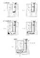
以下、本発明を図示する実施の形態に基づいて説明する。この実施形態は、放射性廃棄物の地層処分に本発明を適用した例である。図1は、地層処分場のアクセス立坑に空気搬送管路を設置する場合の建設段階と操業段階を順に示したものである。図2は、専用の立坑を空気搬送管路として使用する場合の建設段階と操業段階を順に示したものである。図3は、本発明で使用する空気搬送システムの概要を示したものである。
【0041】
[A]地層処分場のアクセス立坑に空気搬送管路を設置する場合
(1) 立坑建設時であり、図1(i) に示すように、地上からアクセス立坑2aを掘削すると共に空気搬送管路10を鉛直に配設し、立坑2aの掘進に伴い管路10を順次下方に延伸させ、掘削ずりaを搬送容器(カブセル)11に収納し、負圧による吸引方式や正圧による圧入方式の空気圧輸送により地上に搬出する。
【0042】
(2) 立坑建設時であり、図1(ii)に示すように、吹付コンクリートb等の資機材を搬送容器11に収納し、吸引方式や圧入方式の空気圧輸送により地上から掘進途中の立坑2aの底部に搬入する。この掘削ずりaの搬出と資機材bの搬入は、交互に行い、掘進しながら上部に吹付コンクリートbを施工していく。
【0043】
(3) 水平坑道建設時であり、図1(iii) に示すように、処分坑道3の掘削ずりaを搬送容器11に収納し、吸引方式や圧入方式の空気圧輸送により地上に搬出する。
【0044】
(4) 水平坑道建設時であり、図1(iv)に示すように、処分坑道3の吹付コンクリートb等の資機材を搬送容器11に収納し、吸引方式や圧入方式の空気圧輸送により地上から立坑2aの底部における処分坑道3内に搬入する。
【0045】
なお、水平坑道建設時においては、掘削ずりaの搬出または資機材の搬入を他の立坑や坑道等の経路または他の搬送手段により行う場合もある。
【0046】
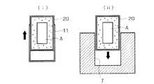
(5) 操業時であり、図1(v) に示すように、廃棄体Aおよび緩衝材Bを搬送容器11に収納するなどして(後に詳述)、吸引方式や圧入方式の空気圧輸送により地上から処分坑道3内に搬入し、処分孔7内に廃棄体Aを定置埋設する。
【0047】
なお、定置のための移送は無人遠隔定置装置などを用いてもよいし、空気搬送管路10を処分坑道3内にも配設し、定置のための移送に利用することも可能である。
【0048】
空気搬送管路10は、後述するように地下施設の換気の排気坑として兼用でき、別の換気系統を整備する必要がなく、経済性が向上する。
【0049】
[B]専用の立坑を空気搬送管路として使用する場合
(1) 立坑建設時であり、図2(i) に示すように、搬送用の専用立坑12を堀上がり工法のレイズポーラ等により建設する。掘削された立坑12の内周面には、後述するようにライニング材とメンブレンを施し、立坑12を空気搬送管路13として利用する。また、この搬送用の専用立坑12は後述するように換気立坑も兼ねている。
【0050】
(2) 水平坑道建設時であり、図2(ii)に示すように、処分坑道3の掘削ずりaを搬送容器11に収納し、専用立坑による空気搬送管路13を利用し、吸引方式や圧入方式の空気圧輸送により地上に搬出する。
【0051】
(3) 水平坑道建設時であり、図2(iii) に示すように、処分坑道3の吹付コンクリートb等の資機材を搬送容器11に収納し、専用立坑による空気搬送管路13を利用し、吸引方式や圧入方式の空気圧輸送により地上から処分坑道3内に搬入する。
【0052】
なお、水平坑道建設時においては、掘削ずりaの搬出または資機材の搬入を他の立坑や坑道等の経路または他の搬送手段により行う場合もある。
【0053】
(4) 操業時であり、図2(iv)に示すように、廃棄体Aおよび緩衝材Bを搬送容器11に収納するなどして(後に詳述)、専用立坑による空気搬送管路13を利用し、吸引方式や圧入方式の空気圧輸送により地上から処分坑道3内に搬入し、処分孔7内に廃棄体Aを定置埋設する。
【0054】
なお、この場合も、定置のための移送は無人遠隔定置装置などを用いてもよいし、空気搬送管路10を処分坑道3内にも配設し、定置のための移送に利用することも可能である。
【0055】
以上のように、立坑12自体を空気搬送装置の一部とすることにより、▲1▼立坑側壁にライニング材とメンブレンを設置するだけで、容易に強度と気密性を備えた空気搬送管路を形成することができる。▲2▼コンパクトな搬送設備でよく、立坑径を小さくすることができる。以上から、経済性が向上する。▲3▼後述するように地下施設の換気の排気坑として兼用でき、別の換気系統を整備する必要がなく、経済性が向上する。
【0056】
[C]空気搬送システム
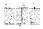
図3は、[B]の空気搬送管路13の例であり、岩盤を掘削して建設した専用立坑12の内壁面にライニング材(コンクリート等)14とメンブレン(ステンレス鋼板等)15を施して、強度と気密性を備えた空気搬送管路13を形成する。なお、[A]の空気搬送管路10は、単位鋼管を接続して構成される。
【0057】
このような空気搬送管路13(または10)の上部にブロア等の排気装置16を設置し、下部に空気弁17を設け、上部から空気を排気し、下部から空気を吸気することで、搬送容器11の上下の気圧差を管理し、搬送容器11の搬送速度(上昇速度および下降速度)を制御する。なお、図示例は負圧による吸引方式であるが、これに限らず、ブロア等を下部に設ける正圧による圧入方式や上部と下部の両方に設ける方式もある。
【0058】
このような空気搬送方式であれば、▲1▼従来の立坑方式のワイヤーロープが無くなり、深度の制約が無くなり、大深度でも搬送が可能になる。▲2▼搬送速度が向上する。▲3▼搬送システムは差圧管理のみでシンプルであるため、搬送の信頼性が向上する。▲4▼搬送設備機構がシンプルであるため、故障に強く、メンテナンスや維持管理が容易となる。▲5▼精密な搬送機械が必要なく、経済性が向上する。
【0059】
空気弁17は、図3(c) に示すように、一種の逆止弁であり、搬送時の空気の流れにより自動的に開状態となり、地下施設から空気搬送管路13への空気流入を可能とし、また、システム故障時や自由落下時の空気の逆流により自動的に閉状態となり、空気搬送管路13から地下施設への空気流出を防止する構造である。
【0060】
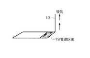
従って、▲1▼空気搬送システムを稼動させることにより、自動的に空気弁17が開となり、地下施設内の空気を吸引して地上に排出し、図4に示すように、地下施設管理区域19の換気を行うことができる。即ち、搬送専用の立坑12を換気用立坑として兼用でき、かつ、別の換気系統を整備する必要がないため、経済性を向上させることができる。▲2▼搬送中に電源供給が停止する等して搬送容器11等が自由落下状態になっても、空気の逆流により自動的に空気弁17が閉じ、立坑下部の密閉状態の空気の圧縮作用(立坑のダンパー効果)により、廃棄体Aが施設下部に激突して災害が発生するのを防止する。即ち、フェイルセーフ機能が確保される。
【0061】
また、図3(a) に示すように、空気搬送管路13の上部および下部には、脱着装置18が設けられている。空気搬送管路13の上部および下部は、鋼管から構成されており、この鋼管に対して可動鋼管を横行台車により横スライドさせるなどして搬送容器11等の積み込み、積み降ろしを行う。
【0062】
図5は、搬送容器11の搬入工程の1例を示したものであり、(1) 資機材、廃棄体あるいは緩衝材等を収納した搬送容器11を上部の脱着装置18に挿入し、この脱着装置18を空気搬送管路13の上部にセットする。(2) 排気装置16を稼動させ、搬送容器11の上下の気圧差を管理しつつ搬送容器11を地下へ搬送する。(3) 下部の脱着装置18を空気搬送管路13の下部から取り出し、脱着装置18から搬送容器11を取り出す。
【0063】
[D]廃棄体および緩衝材
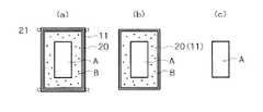
図6は、搬送体の種々の形態を示したものである。図6(a),(b) は、廃棄体A(オーバーパック)と緩衝材(ベントナイト混合土)Bを一体化して搬送し、一体化した廃棄体Aと緩衝材Bを定置埋設する場合である。図6(a) では、廃棄体Aと緩衝材Bを地上施設で一体化容器20に格納し、さらにこの一体化容器20を搬送容器11に挿入して搬送する。図6(b) では、廃棄体Aと緩衝材Bを地上施設で一体化容器20に格納し、この一体化容器20を搬送容器11として用い、そのまま搬送する。
【0064】
また、これに限らず、図6(c) に示すように、搬送容器を使用せず、廃棄体Aをそのまま搬送することもできる。さらに、搬送容器11に廃棄体Aを収納して搬送することもできる。緩衝材Bは、搬送容器11に収納して別途搬送する。
【0065】
また、図6(a) に示すように、搬送容器11の外周部には、車輪等のスペーサ21を設置することで、搬送時に容器による空気搬送管路のメンブレンの損傷が抑えられ、空気搬送装置の耐久性が向上する。さらに、搬送容器11の外周部には必要に応じてシール材が設けられる。
【0066】
図7に示すように、図6(a) の搬送容器11を用いる場合、搬送容器11から一体化容器20を取り出し、この一体化容器20をそのまま処分孔7内に定置埋設する。図6(b) の場合も、搬送されてきた搬送容器を兼ねる一体化容器20をそのまま処分孔7内に定置埋設する。
【0067】
以上のような廃棄体Aと緩衝材Bの一体化容器を使用することにより、▲1▼従来技術のように地下で廃棄体Aと緩衝材Bを個々に定置する必要がなく、定置作業を安全に迅速に確実に低コストで行うことができると共に、定置の信頼性および緩衝材の品質が向上する。▲2▼処分孔7内に一体化容器20をそのまま定置することにより、操業期間中(一体化容器に腐食孔が発生するまで)は、緩衝材Bに地下水が浸入することがなく、緩衝材が膨潤しないため、該当期間中の再取り出しが容易となる。また、一体化容器20毎に容易に取り出すことができる。
【0068】
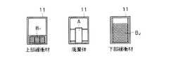
また、廃棄体Aと緩衝材Bを一体化したものだけではなく、それぞれ個別に空気搬送することも可能である。図6(c) のように廃棄体Aをそのまま搬送する場合、専用立坑12等の内径を一層小さくすることが可能である。搬送容器11を用いて廃棄体Aと緩衝材Bを個別に搬送する場合には、例えば図8に示すように、3つの搬送容器11内にそれぞれ上部緩衝材B1、廃棄体A、下部緩衝材B2を収納して搬送し、処分孔7内に下部緩衝材B2を定置した後、廃棄体Aを定置し、その上に上部緩衝材B1を定置する。また、建設時には、このような搬送容器11に掘削ずりや吹付コンクリート等の資機材を収納して搬送することができる。
【0069】
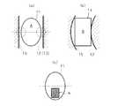
図9は、立坑12の鉛直精度に依存しない空気搬送システムの例を示したものである。立坑の鉛直に対する掘削精度に依らず搬送可能とするため、図9(a) に示すように、搬送容器11や廃棄体Aなどの搬送体と周囲のメンブレム15とが立坑12と垂直な断面を含む平面だけで接する構造、即ち、搬送体の形状を例えば球形や卵形とする。
【0070】
図9(b) に示すように、立坑12が鉛直方向に多少変形していても、搬送体の形状を球形や卵形等とすることにより安全に搬送することが可能となる。さらに、搬送中の安定性および着地時の安定性を向上させるために、図9(c) に示すように、搬送容器11の下部に廃棄体Aを配置するなどして、搬送体の重心を搬送体とメンブレンとの接点より低くする。
【0071】
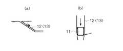
また、搬送用の専用立坑12は、鉛直である必要はなく、図10(a) に示すような斜坑でも、また曲線(搬送容器等が通過可能な曲率を持った曲線)を部分的に有するものでもよい。
【0072】
さらに、立坑のダンパー効果を最大限に利用し、自由落下状態での搬送も可能である。自由落下方式の搬送を採用する場合、立坑内に水等の液体を満たすことによりダンパー効果を向上させることも可能である。また、立坑のダンパー効果により搬送物の落下に対するフェールセーフ性は高いが、図10(b) に示すように、立坑12の下部の径を徐々に小さくすることで、更に安全性が高くなる。
【0073】
また、差圧管理方式は、搬送物が軽量物(搬送装置を大気圧で揚重可能)である場合には吸引方式(負圧方式)、重量物である場合には圧入方式(正圧方式)とする。
【0074】
なお、以上は、地層処分場について説明したが、これに限らず、山岳トンネル等のトンネルの建設にも本発明の空気搬送システムを用いることができる。また、放射性廃棄物の地層処分は、処分孔による定置方式について説明したが、これに限らず、その他の定置方式にも本発明を適用できることは言うまでもない。また、放射性廃棄物に限らず、その他の廃棄物の埋設処分にも適用が可能である。
【0075】
【発明の効果】
(1) 本発明は、掘削ずり、資機材、廃棄体および緩衝材等の搬送に空気搬送システムを用い、搬送体の上下の気圧差により搬送体を搬出・搬入するため、▲1▼従来のワイヤーロープを無くすことができるため、深度の制約が無くなり、大深度でも搬送が可能になり、▲2▼従来のワイヤーロープ方式と比べて搬送速度を早くすることができ、▲3▼搬送設備が差圧管理のみであるため、搬送の信頼性が向上し、▲4▼搬送設備機構がシンプルであるため、故障に強く、メンテナンスや維持管理が容易となり、▲5▼精密な搬送機械が必要なく、経済性が向上する。以上から、地層処分場や山岳トンネル等の建設における掘削ずり等の搬出および資機材等の搬入、地層処分場における廃棄体の搬入、地層処分場における廃棄体と緩衝材の定置作業を安全に迅速に確実に低コストで行うことができる。
【0076】
(2) 空気搬送システムを稼動することにより、地下施設内やトンネル内の空気を吸引することができ、地下施設内やトンネル内の換気を行うことができる。空気搬送管路を換気用の立坑として兼用でき、かつ、別の換気系統を整備する必要が無いため、経済性が向上する。
【0077】
(3) 立坑等自体を空気搬送システムの一部とすることにより、▲1▼立坑等の側壁にライニング材やメンブレム等を設置するだけで、容易に強度と気密性を備えた空気搬送管路を形成することができ、▲2▼ コンパクトな搬送設備とすることができ、立坑等の径を小さくすることができる。これにより、経済性が向上する。
【0078】
(4) 放射性廃棄物の地層処分において搬送容器を活用し、廃棄体と緩衝材を地上設備で一体化する。これを地下施設の処分空間内に搬送容器ごと定置埋設することにより、▲1▼従来技術のように地下で廃棄体と緩衝材を個々に定置する必要がなく、定置作業を安全に迅速に確実に低コストで行うことができると共に、定置の信頼性および緩衝材の品質が向上する。▲2▼緩衝材定置後、一定期間地下水が浸入することがなく、膨潤しないため、再取り出しが容易となり、また、取り出し作業も容易に行うことができる。
【0079】
(5) 空気搬送管路の下部に空気弁を設けることにより、立坑等から地下施設やトンネル内への空気流出が防止されるため、搬送中に電源供給が停止するなどして搬送体が自由落下状態となっても、空気搬送管路の下部の空気の圧縮作用によるダンパー効果により、搬送体が地下施設等の下部に激突して災害を招くことがない。
【図面の簡単な説明】
【図1】本発明の建設方法と地層処分方法の1例であり、地層処分場のアクセス立坑に空気搬送管路を設置する場合の建設段階と操業段階を工程順に示した断面図である。
【図2】本発明の建設方法と地層処分方法の1例であり、専用の立坑を空気搬送管路として使用する場合の建設段階と操業段階を工程順に示した断面図である。
【図3】本発明で使用する空気搬送システムの概要を示したものであり、(a) は全体の断面図、(b) は搬送管路の部分拡大断面図、(c) は空気弁の部分拡大断面図である。
【図4】図2の専用立坑による換気システムを示す概略斜視図である。
【図5】搬送容器の搬入工程の1例を示す断面図である。
【図6】搬送体の構造の種々の例を示す断面図である。
【図7】搬送体の処分孔への定置を示す断面図である。
【図8】搬送容器と搬送物を示す断面図である。
【図9】搬送体の形状、構成の他の例を示す断面図である。
【図10】立坑の他の例と立坑下部の形状例を示す断面図である。
【図11】放射性廃棄物の地層処分場と従来の搬送・定置方法を示す斜視図と断面図である。
【符号の説明】
A……廃棄体
B……緩衝材
1……地上施設
2……アクセス坑道
2a…アクセス立坑
2b…アクセス斜坑
3……処分坑道
4……主要坑道
5……連絡坑道
6……処分パネル
7……処分孔
10……空気搬送管路
11……搬送容器(カブセル)
12……搬送用の専用立坑
13……空気搬送管路
14……ライニング材
15……メンブレン
16……排気装置
17……空気弁
18……脱着装置
19……地下施設管理区域
20……一体化容器
21……スぺーサ[0001]
BACKGROUND OF THE INVENTION
The present invention relates to a construction method of a geological disposal site for radioactive waste or a tunnel such as a mountain tunnel by an air conveyance system, and a geological disposal method for radioactive waste or the like.
[0002]
[Prior art]
In the geological disposal of radioactive waste, the radioactive waste is stabilized as a vitrified body, and this vitrified body is hermetically stored in a thick steel plate sealed container called an overpack. It is to be buried in a bedrock at a depth of several hundred to several hundreds of meters through a buffer material (bentonite mixed soil, etc.).
[0003]
FIG. 11 shows an example of a geological disposal site, in order to place an access tunnel 2 (
[0004]
At the construction stage, construction of ground facilities and underground facilities will be carried out. In the operational phase, the main tasks are receiving glass solids, filling in the overback, producing cushioning materials, transporting and placing wastes and cushioning materials, and backfilling the disposal and main tunnels. At the closing stage, the main work is backfilling the connecting and access tunnels, and dismantling and removing ground facilities.
[0005]
In such a geological disposal site, methods for transporting wastes and buffer materials from the ground to the basement, and methods for placing waste materials and buffer materials in the disposal space are as follows.
[0006]
(1) Transporting waste and cushioning material (see Fig. 11)
(a) A method in which the waste body A and the buffer material B are transported from the ground to the underground by the
[0007]
(b) A method of transporting the waste A and the buffer material B from the ground to the basement with a dedicated
[0008]
(2) Placement method of waste and cushioning material (see Fig. 11)
FIG. 11 shows an example of a disposal hole vertical installation method in which a plurality of
[0009]
In addition to the above-mentioned vertical arrangement method for disposal holes, the waste embedding method is not limited to the above-mentioned disposal hole vertical placement method, but a horizontal or inclined disposal tunnel is formed in parallel at a predetermined interval between each pair of left and right main tunnels. Disposal tunnel horizontal installation method in which waste A is placed sideways in the tunnel longitudinal direction with a predetermined interval, vertical disposal tunnel (disposition shaft) between the upper main tunnel and the lower tunnel is a predetermined interval Disposal vertical shafts in which the waste A is vertically placed in each disposal tunnel with a predetermined interval in the vertical direction, horizontal disposal holes on both side walls of the disposal tunnel There is a disposal hole horizontal placement system in which the waste body A is placed sideways in each disposal hole, and the like is excavated and formed at intervals in the longitudinal direction of the tunnel.
[0010]
Further, the buffer material B is a mixed soil containing bentonite as a main component, and the bentonite mixed soil is a material having a dynamic buffer function, a low water permeability performance, and a low diffusion performance of radioactive substances. It can reduce the influence of groundwater and delay the migration of nuclides.
[0011]
[Problems to be solved by the invention]
(1) Problems with conventional methods for transporting waste and cushioning materials
(a) In the case of the vertical shaft method, there is a possibility that the waste A will fall, and if it falls, it may cause a serious disaster.
[0012]
(b) In the case of the vertical shaft system, as the depth increases, the weight of the wire rope of the
[0013]
(c) In the case of the vertical shaft method, it is difficult to increase the lifting speed because of the risk of the waste A falling and reducing the load on the wire rope.
[0014]
(d) In the case of the inclined shaft method, a load is applied to the speed reducing (stopping) device of the
[0015]
(e) In the case of the tilt shaft method, the reliability of the traveling
[0016]
(f) In the case of the inclined shaft method, it is necessary to install ancillary equipment such as rails and pulling wires, which increases costs.
[0017]
(2) Problems with conventional waste body and cushioning placement methods
(a) In order to individually place the waste body A and the buffer material B in the disposal hole or the like, an extremely sophisticated unmanned
[0018]
(b) In the unlikely event that installation fails, remote unattended recovery is difficult.
[0019]
(c) When the buffer material is divided into blocks and the buffer material block is placed inside a disposal hole or the like, it is difficult to ensure the quality of the buffer material after placement.
[0020]
The above is the case of the operation stage. Even at the construction stage, the
[0021]
The present invention has been made to solve the above-mentioned problems. The purpose of the present invention is to carry out excavation excavation and materials and equipment when constructing a tunnel such as a disposal tunnel of a geological disposal site or a mountain tunnel. A method for constructing underground tunnels that can be safely and quickly carried out at low cost, and that waste can be carried safely and quickly at low cost in geological disposal sites. It is an object of the present invention to provide a geological disposal method capable of safely and promptly and reliably performing a placement operation of a waste body and a buffer material on a site, and easily ensuring the quality of the buffer material.
[0022]
[Means for Solving the Problems]
[0023]
The first half of this
[0024]
Claim 2 of the present invention providesRadioactive waste Is a geological disposal method that geologically disposes in the underground disposal space,A negative pressure suction system that installs an exhaust system at the top of the air transport line, a positive pressure press-in system that installs an exhaust system at the bottom of the air transport system, or an exhaust system that is installed at the top and bottom of the air transport system In the construction stage, using the air transport system that manages the pressure difference between the top and bottom of the transport container in the air transport pipeline and controls the rising speed and the descending speed of the transport container, Drilled shaft or tilt shaft itselfIn the above Air conveyance pipelineConfigure And the air conveying pipeAnd transport container , Unload excavation of underground mine to the ground, or carry underground mine materials and equipment underground,In the operational phase, Ground facilitiesIn, an airtight container in which radioactive waste is sealed and stored as a glass solidified body, and a buffer material having a mechanical buffer function, low water permeability, and radioactive material low diffusion performance surrounding the airtight container are stored in an integrated container, This integrated container is stored in a transport container, or the integrated container is used as a transport container, Utilizing the air conveying pipeline,The transport container that stores the integrated container or the integrated container itself Air transport to the underground mine, the aboveIntegrated container As it isDisposal tunnels and disposal holes It is a geological disposal method characterized in that it is buried in place. In this case as well, there is a case where both excavation shear and material and equipment are carried in the underground mine tunnel by air conveyance pipes, and either excavation shear and material and equipment are carried in by air conveyance pipes. is there.
[0025]
The first half of this
[0027]
The second half of
[0028]
[0029]
The second half of
[0031]
Book In the invention, the waste body (so-called overpack) itself can be transported by air, or the waste body can be stored in a transport container and transported by air, but the waste body and the cushioning material are stored in an integrated container. The integrated container is stored in the transport container and transported by air, or the integrated container is transported by air as the transport container, and the integrated container is placed in the disposal space.Do .
[0032]
Of the
[0033]
That is, the air conveyance system of the present invention employs a suction method in which an exhaust device is installed in the upper part of the air conveyance pipeline, a press-in method in which an exhaust device is installed in the lower part, and a method in which exhaust devices are installed in the upper and lower parts. However, a check valve type air valve is installed in the lower part of the air conveyance pipeline, and air is supplied into the pipeline or underground facilities and tunnels are efficiently ventilated while the valve is open. A damper effect by air can be obtained. For this reason, even if it becomes a free fall state by failure of an equipment etc., since a damper effect can be expected, safety is secured.
[0034]
In the present invention, the vertical shaft is excavated vertically, and the inclined shaft is inclined and has a straight one or a curved portion excavated.
[0035]
In the present invention, (1) the air transport system is used and the transport body is carried out and loaded by the pressure difference between the upper and lower sides of the transport body. (1) Since the conventional wire rope can be eliminated, there is no depth limitation. , Transport is possible even at large depths, and (2) the transport speed can be increased compared to conventional wire rope systems, and (3) transport reliability is improved because transport equipment is only differential pressure management. However, (4) since the transport equipment mechanism is simple, it is resistant to failure, facilitates maintenance and maintenance, and (5) does not require a precise transport machine, thereby improving economy. From the above, it is safe and quick to carry out excavation and transport of materials and equipment for construction of geological disposal sites and mountain tunnels, carry in waste materials in geological disposal sites, and place waste and buffer materials in geological disposal sites. Can be reliably performed at low cost.
[0036]
(2) By operating the air transport system, air in the underground facility or tunnel can be sucked, and ventilation in the underground facility or tunnel can be performed. Since the air conveying pipe can be used as a vertical shaft for ventilation and it is not necessary to prepare a separate ventilation system, the economy is improved.
[0037]
(3) By making the shafts, etc. part of the air transportation system, (1) Air transportation pipelines with strength and airtightness can be easily installed just by installing lining materials, membranes, etc. on the side walls of the shafts. (2) A compact transport facility can be formed, and the diameter of a shaft or the like can be reduced. Thereby, economic efficiency improves.
[0038]
(4) Utilize transport containers in the geological disposal of radioactive waste, and integrate waste bodies and cushioning materials with ground facilities. By embedding the entire transport container in the disposal space of the underground facility, (1) there is no need to place the waste A and the buffer material B individually in the basement as in the prior art, and the placement work can be performed quickly and safely. It is possible to reliably perform the process at a low cost, and the reliability of the stationary position and the quality of the cushioning material are improved. {Circle around (2)} After placing the buffer material, the groundwater does not enter for a certain period and does not swell, so that it can be easily taken out again and can be taken out easily.
[0039]
(5) By providing an air valve in the lower part of the air conveyance pipeline, air outflow from a shaft or the like to underground facilities or tunnels is prevented, so the power supply can be freely stopped by, for example, stopping power supply during conveyance Even in the fall state, the transporter does not collide with the lower part of the underground facility or the like due to the damper effect due to the compression action of the air in the lower part of the air conveyance pipe line, causing a disaster.
[0040]
DETAILED DESCRIPTION OF THE INVENTION
Hereinafter, the present invention will be described based on the illustrated embodiment. This embodiment is an example in which the present invention is applied to geological disposal of radioactive waste. FIG. 1 shows a construction stage and an operation stage in order in the case of installing an air conveyance pipeline in an access shaft of a geological disposal site. FIG. 2 shows a construction stage and an operation stage in order when a dedicated shaft is used as an air conveyance pipe. FIG. 3 shows an outline of an air conveyance system used in the present invention.
[0041]
[A] When installing an air conveyance pipeline in the access shaft of a geological disposal site
(1) At the time of construction of the shaft, as shown in FIG. 1 (i), the
[0042]
(2) At the time of construction of the shaft, as shown in Fig. 1 (ii), materials such as sprayed concrete b are stored in the
[0043]
(3) At the time of horizontal mine construction, as shown in FIG. 1 (iii), the excavation shear a of the
[0044]
(4) At the time of horizontal mine construction, as shown in Fig. 1 (iv), materials such as sprayed concrete b of the
[0045]
When constructing a horizontal mine shaft, the excavation shear a or material / material may be carried in by a route such as another shaft or mine shaft or other transport means.
[0046]
(5) At the time of operation, as shown in FIG. 1 (v), the waste body A and the buffer material B are accommodated in the transfer container 11 (detailed later), etc. It is carried into the
[0047]
In addition, the unmanned remote stationary apparatus etc. may be used for the transfer for stationary, and the air
[0048]
As will be described later, the
[0049]
[B] When using a dedicated shaft as an air conveyance pipe
(1) At the time of vertical shaft construction, as shown in Fig. 2 (i), a dedicated
[0050]
(2) At the time of horizontal tunnel construction, as shown in Fig. 2 (ii), the excavation shear a of the
[0051]
(3) At the time of horizontal tunnel construction, as shown in Fig. 2 (iii), materials and equipment such as sprayed concrete b of the
[0052]
When constructing a horizontal mine shaft, the excavation shear a or material / material may be carried in by a route such as another shaft or mine shaft or other transport means.
[0053]
(4) At the time of operation, as shown in FIG. 2 (iv), the waste transport body A and the buffer material B are accommodated in the transport container 11 (detailed later), and the
[0054]
In this case as well, an unmanned remote placement device or the like may be used for the transfer for placement, or the air
[0055]
As described above, by making the
[0056]
[C] Pneumatic transfer system
FIG. 3 shows an example of the
[0057]
An
[0058]
With such an air conveyance method, (1) a conventional shaft type wire rope is eliminated, depth restrictions are eliminated, and conveyance is possible even at large depths. (2) The conveyance speed is improved. (3) Since the transfer system is simple with only differential pressure management, the reliability of transfer is improved. (4) Since the transport equipment mechanism is simple, it is resistant to failure and easy to maintain and maintain. (5) There is no need for a precise transfer machine, and the economy is improved.
[0059]
As shown in FIG. 3 (c), the
[0060]
Accordingly, (1) by operating the air transfer system, the
[0061]
Further, as shown in FIG. 3 (a), a
[0062]
FIG. 5 shows an example of the carrying-in process of the
[0063]
[D] Waste and cushioning material
FIG. 6 shows various forms of the carrier. 6 (a) and 6 (b) show a case where waste body A (overpack) and buffer material (bentonite mixed soil) B are integrated and transported, and the integrated waste body A and buffer material B are fixedly buried. is there. In FIG. 6A, the waste body A and the buffer material B are stored in the
[0064]
In addition to this, as shown in FIG. 6C, the waste body A can be transported as it is without using a transport container. Furthermore, the waste body A can be accommodated in the
[0065]
Also, as shown in FIG. 6 (a), by installing a
[0066]
As shown in FIG. 7, when the
[0067]
By using the integrated container of the waste body A and the buffer material B as described above, (1) it is not necessary to place the waste body A and the buffer material B individually in the basement as in the prior art, so that the placement work can be performed. It can be performed safely, quickly and reliably at low cost, and the reliability of stationary and the quality of the cushioning material are improved. (2) By placing the
[0068]
Moreover, it is possible not only to integrate the waste body A and the buffer material B but also to individually carry the air. When the waste A is transported as it is as shown in FIG. 6 (c), the inner diameter of the
[0069]
FIG. 9 shows an example of an air conveyance system that does not depend on the vertical accuracy of the
[0070]
As shown in FIG. 9 (b), even if the
[0071]
Further, the dedicated
[0072]
Furthermore, it can be transported in a free-fall state by making maximum use of the damper effect of the shaft. In the case of adopting a free-fall type conveyance, it is possible to improve the damper effect by filling the shaft with a liquid such as water. Moreover, although the fail-safe property with respect to the fall of a conveyed product is high by the damper effect of a shaft, safety | security becomes still higher by making the diameter of the lower part of the
[0073]
In addition, the differential pressure management system is a suction system (negative pressure system) when the transported object is light (the transport device can be lifted at atmospheric pressure), and a press-in system (positive pressure system) when it is heavy. ).
[0074]
In addition, although the geological disposal site was demonstrated above, it is not restricted to this, The pneumatic conveyance system of this invention can be used also for construction of tunnels, such as a mountain tunnel. In addition, although the geological disposal of radioactive waste has been described with respect to a stationary method using a disposal hole, it is needless to say that the present invention can be applied to other stationary methods as well. Moreover, the present invention can be applied not only to radioactive waste but also to disposal of other waste.
[0075]
【The invention's effect】
(1) The present invention uses an air transport system for transporting excavations, materials and equipment, waste bodies, cushioning materials, etc., and unloads / loads the transport body due to the difference in pressure above and below the transport body. Since the wire rope can be eliminated, there is no restriction on depth, and transport is possible even at large depths. (2) The transport speed can be increased compared to the conventional wire rope system. Since only differential pressure management is used, transport reliability is improved. (4) The transport equipment mechanism is simple, so it is resistant to breakdowns and easy to maintain and maintain. (5) No need for precision transport machines , Improve the economy. From the above, it is safe and quick to carry out excavation and transport of materials and equipment for construction of geological disposal sites and mountain tunnels, carry in waste materials in geological disposal sites, and place waste and buffer materials in geological disposal sites. Can be reliably performed at low cost.
[0076]
(2) By operating the air transport system, air in the underground facility or tunnel can be sucked, and ventilation in the underground facility or tunnel can be performed. Since the air conveying pipe can be used as a vertical shaft for ventilation and it is not necessary to prepare a separate ventilation system, the economy is improved.
[0077]
(3) By making the shafts, etc. part of the air transportation system, (1) Air transportation pipelines with strength and airtightness can be easily installed just by installing lining materials, membranes, etc. on the side walls of the shafts. (2) A compact transport facility can be formed, and the diameter of a shaft or the like can be reduced. Thereby, economic efficiency improves.
[0078]
(4) Utilize transport containers in the geological disposal of radioactive waste, and integrate waste bodies and cushioning materials with ground facilities. By embedding this with the transport container in the disposal space of the underground facility, (1) there is no need to place waste and cushioning material underground in the same way as in the prior art, and the placement work can be performed safely and quickly. Can be carried out at low cost, and the reliability of the placement and the quality of the cushioning material are improved. {Circle around (2)} After placing the buffer material, the groundwater does not enter for a certain period and does not swell, so that it can be easily taken out again and can be taken out easily.
[0079]
(5) By providing an air valve in the lower part of the air conveyance pipeline, air outflow from a shaft or the like to underground facilities or tunnels is prevented, so the power supply can be freely stopped by, for example, stopping power supply during conveyance Even in the fall state, the transporter does not collide with the lower part of the underground facility or the like due to the damper effect due to the compression action of the air in the lower part of the air conveyance pipe line, causing a disaster.
[Brief description of the drawings]
BRIEF DESCRIPTION OF DRAWINGS FIG. 1 is an example of a construction method and a geological disposal method according to the present invention, and is a cross-sectional view showing a construction stage and an operation stage in the order of steps when an air conveyance pipeline is installed in an access shaft of a geological disposal site.
FIG. 2 is an example of a construction method and a geological disposal method according to the present invention, and is a cross-sectional view showing a construction stage and an operation stage in the order of processes when a dedicated shaft is used as an air conveyance pipeline.
FIG. 3 shows an outline of an air conveyance system used in the present invention, where (a) is an overall cross-sectional view, (b) is a partial enlarged cross-sectional view of a conveyance pipeline, and (c) is an air valve. It is a partial expanded sectional view.
4 is a schematic perspective view showing a ventilation system using the dedicated shaft shown in FIG. 2; FIG.
FIG. 5 is a cross-sectional view showing an example of a carrying-in process of a transport container.
FIG. 6 is a cross-sectional view showing various examples of the structure of a transport body.
FIG. 7 is a cross-sectional view showing the placement of the transport body in the disposal hole.
FIG. 8 is a cross-sectional view showing a transport container and a transported object.
FIG. 9 is a cross-sectional view showing another example of the shape and configuration of the transport body.
FIG. 10 is a cross-sectional view showing another example of the shaft and an example of the shape of the lower portion of the shaft.
FIG. 11 is a perspective view and a cross-sectional view showing a geological disposal site for radioactive waste and a conventional transport / placement method.
[Explanation of symbols]
A …… Waste body
B …… Buffer material
1 …… Ground facility
2 …… Access tunnel
2a ... Access shaft
2b ... Access inclined shaft
3 …… Disposal tunnel
4 ... Main tunnel
5 …… Communication tunnel
6 …… Disposal panel
7 …… Disposal hole
10 ... Air conveyance pipeline
11 ... Transport container
12 …… Dedicated vertical shaft for transportation
13 …… Air conveyance pipeline
14 ... Lining material
15 …… Membrane
16 …… Exhaust device
17 ... Air valve
18 …… Desorption device
19 …… Underground facility management area
20 …… Integrated container
21 …… Spacer
Claims (3)
Translated fromJapanesePriority Applications (5)
| Application Number | Priority Date | Filing Date | Title |
|---|---|---|---|
| JP2001344537AJP3945225B2 (en) | 2001-11-09 | 2001-11-09 | Geological disposal method using pneumatic conveying system |
| PCT/JP2002/011672WO2003040523A1 (en) | 2001-11-09 | 2002-11-08 | Method of constructing underground gallery by using pneumatic transfer system, and stratum disposal method |
| US10/494,648US7063657B2 (en) | 2001-11-09 | 2002-11-08 | Method of constructing underground gallery by using pneumatic transfer system and stratum disposal method |
| CA002466208ACA2466208A1 (en) | 2001-11-09 | 2002-11-08 | Method of constructing underground gallery by using pneumatic transfer system, and stratum disposal method |
| EP02775513AEP1443177A4 (en) | 2001-11-09 | 2002-11-08 | METHOD FOR BUILDING UNDERGROUND GALLERIES USING PNEUMATIC TRANSFER SYSTEM, AND PERMANENT STRATE STORAGE METHOD |
Applications Claiming Priority (1)
| Application Number | Priority Date | Filing Date | Title |
|---|---|---|---|
| JP2001344537AJP3945225B2 (en) | 2001-11-09 | 2001-11-09 | Geological disposal method using pneumatic conveying system |
Publications (2)
| Publication Number | Publication Date |
|---|---|
| JP2003148097A JP2003148097A (en) | 2003-05-21 |
| JP3945225B2true JP3945225B2 (en) | 2007-07-18 |
Family
ID=19158050
Family Applications (1)
| Application Number | Title | Priority Date | Filing Date |
|---|---|---|---|
| JP2001344537AExpired - Fee RelatedJP3945225B2 (en) | 2001-11-09 | 2001-11-09 | Geological disposal method using pneumatic conveying system |
Country Status (5)
| Country | Link |
|---|---|
| US (1) | US7063657B2 (en) |
| EP (1) | EP1443177A4 (en) |
| JP (1) | JP3945225B2 (en) |
| CA (1) | CA2466208A1 (en) |
| WO (1) | WO2003040523A1 (en) |
Families Citing this family (27)
| Publication number | Priority date | Publication date | Assignee | Title |
|---|---|---|---|---|
| ZA200506893B (en)* | 2003-01-27 | 2006-09-27 | J S Redpath Ltd | Method and apparatus for raise bore drilling and lining a bore hole |
| RU2004105195A (en)* | 2004-02-25 | 2005-08-10 | Лев Николаевич Максимов (RU) | METHOD FOR UNDERGROUND STORAGE OF ECOLOGICALLY HAZARDOUS SUBSTANCES AND DEVICE FOR ITS IMPLEMENTATION |
| US8104998B2 (en)* | 2006-05-18 | 2012-01-31 | Ross Guenther | Hydraulic elevation apparatus and method |
| US7661910B2 (en)* | 2006-05-18 | 2010-02-16 | Ross Guenther | Hydraulic elevation apparatus and method |
| US20120096702A1 (en)* | 2007-09-14 | 2012-04-26 | Alan Kingsley | Automated construction system |
| WO2010023650A1 (en)* | 2008-09-01 | 2010-03-04 | Avner And Yossi Civil Engineering And Projects Ltd. | Method and arrangement for detection and destruction of tunnels |
| JP5331993B2 (en)* | 2008-10-03 | 2013-10-30 | 鹿島建設株式会社 | Air capsule transportation method of waste |
| EP2449213B1 (en) | 2009-06-30 | 2021-10-13 | Technological Resources PTY. Limited | Underground mining |
| JP6323663B2 (en)* | 2014-03-13 | 2018-05-16 | 株式会社大林組 | Artificial barrier structure and overpack recovery method |
| JP6500333B2 (en)* | 2014-03-13 | 2019-04-17 | 株式会社大林組 | Artificial barrier structure and overpack recovery method |
| CN104141500B (en)* | 2014-04-11 | 2016-08-24 | 中国水利水电第十一工程局有限公司 | One hardens sand and gravel stratum cavern con struction method |
| JP6454987B2 (en)* | 2014-06-05 | 2019-01-23 | 株式会社大林組 | Waste collection method |
| JP6180060B1 (en)* | 2016-11-10 | 2017-08-16 | 有限会社モリ | Waste disposal methods |
| MX2019008992A (en) | 2017-02-01 | 2019-12-11 | Hydrostor Inc | A hydrostatically compensated compressed gas energy storage system. |
| WO2018161172A1 (en) | 2017-03-09 | 2018-09-13 | Hydrostor Inc. | A thermal storage apparatus for a compressed gas energy storage system |
| CN108439907A (en)* | 2018-04-27 | 2018-08-24 | 天津城建大学 | A kind of preparation process of cement base dregs concrete |
| CN108561184B (en)* | 2018-04-30 | 2019-04-19 | 西安科技大学 | A kind of energy storage group built under mine and its construction method |
| US12366326B2 (en)* | 2018-05-17 | 2025-07-22 | Hydrostor Inc. | Reuse of construction shafts in compressed air energy storage systems |
| US12297056B2 (en) | 2018-05-17 | 2025-05-13 | Hydrostor Inc. | Construction elements and maintenance methods for compressed air energy storage systems |
| AU2020209193A1 (en) | 2019-01-15 | 2021-08-05 | Hydrostor Inc. | A compressed gas energy storage system |
| WO2020160635A1 (en) | 2019-02-08 | 2020-08-13 | Hydrostor Inc. | A compressed gas energy storage system |
| US10878972B2 (en)* | 2019-02-21 | 2020-12-29 | Deep Isolation, Inc. | Hazardous material repository systems and methods |
| US11835023B2 (en) | 2019-02-27 | 2023-12-05 | Hydrostor Inc. | Hydrostatically compensated caes system having an elevated compensation liquid reservoir |
| CN113266124A (en)* | 2021-04-16 | 2021-08-17 | 华东勘测设计院(福建)有限公司 | Smoke exhaust shaft structure and construction method thereof |
| CN117005909B (en)* | 2023-08-21 | 2025-08-19 | 中国矿业大学 | Coal-based solid waste disposal and compressed air energy storage method |
| WO2025085394A1 (en)* | 2023-10-15 | 2025-04-24 | David Hussey | Borehole pneumatic elevator for underground delivery system |
| KR102665799B1 (en)* | 2023-12-05 | 2024-05-17 | 한국원자력환경공단 | System and method for monitoring the smuggling of spent nuclear fuel disposed in deep geological disposal facilities |
Family Cites Families (13)
| Publication number | Priority date | Publication date | Assignee | Title |
|---|---|---|---|---|
| US4184792A (en)* | 1976-11-29 | 1980-01-22 | Turnbo August Z | Vacuum-tube mass-transit system |
| SU1151502A1 (en)* | 1978-12-25 | 1985-04-23 | Karagandinskij Polt Institut | Pneumatic mine hoist |
| US4316682A (en)* | 1980-02-25 | 1982-02-23 | Atlantic Richfield Company | Ore carrier |
| FR2526574A1 (en)* | 1982-05-05 | 1983-11-10 | Commissariat Energie Atomique | RADIOACTIVE WASTE DISPOSAL METHOD AND GEOLOGICAL FACILITY FOR THE EVACUATION OF THESE WASTE |
| JPH0631878B2 (en) | 1988-11-29 | 1994-04-27 | 三井建設株式会社 | How to transfer capsules to deep underground |
| JPH04326954A (en)* | 1991-04-25 | 1992-11-16 | Mitsui Constr Co Ltd | Disposing apparatus of waste material at building site |
| JP2997969B2 (en) | 1992-06-16 | 2000-01-11 | 三井造船株式会社 | Goods transportation system in deep underground |
| RU2081327C1 (en)* | 1992-11-04 | 1997-06-10 | Андрей Степанович Морин | Pneumatic lift |
| JP3009985B2 (en) | 1993-10-06 | 2000-02-14 | 住友金属工業株式会社 | Vertical transport device and vertical transport method for tunnel construction vehicles |
| JPH10290968A (en) | 1997-04-21 | 1998-11-04 | Ishikawajima Harima Heavy Ind Co Ltd | Water barrier material for burying waste |
| JP3418556B2 (en) | 1998-07-28 | 2003-06-23 | 住友金属工業株式会社 | Capsule transport equipment |
| JP3803211B2 (en) | 1999-07-26 | 2006-08-02 | 鹿島建設株式会社 | Capsule transport equipment |
| JP2001158532A (en) | 1999-12-02 | 2001-06-12 | Kansai Sekkei Kk | Capsule transport equipment |
- 2001
- 2001-11-09JPJP2001344537Apatent/JP3945225B2/ennot_activeExpired - Fee Related
- 2002
- 2002-11-08CACA002466208Apatent/CA2466208A1/ennot_activeAbandoned
- 2002-11-08USUS10/494,648patent/US7063657B2/ennot_activeExpired - Fee Related
- 2002-11-08WOPCT/JP2002/011672patent/WO2003040523A1/enactiveApplication Filing
- 2002-11-08EPEP02775513Apatent/EP1443177A4/ennot_activeWithdrawn
Also Published As
| Publication number | Publication date |
|---|---|
| US20050004416A1 (en) | 2005-01-06 |
| EP1443177A1 (en) | 2004-08-04 |
| US7063657B2 (en) | 2006-06-20 |
| EP1443177A4 (en) | 2005-04-13 |
| CA2466208A1 (en) | 2003-05-15 |
| JP2003148097A (en) | 2003-05-21 |
| WO2003040523A1 (en) | 2003-05-15 |
Similar Documents
| Publication | Publication Date | Title |
|---|---|---|
| JP3945225B2 (en) | Geological disposal method using pneumatic conveying system | |
| CN109944610B (en) | Method for rebuilding refuse landfill by using abandoned coal mine roadway | |
| CN114855820A (en) | Construction method for removing multi-ring inner support of special-shaped deep foundation pit | |
| CN103643678A (en) | Deep-foundation-pit container-type earth excavating and transporting method | |
| US8104998B2 (en) | Hydraulic elevation apparatus and method | |
| CN217632432U (en) | Upward hard rock tunneling device | |
| RU2158826C2 (en) | Method of mine construction for small kimberlite pipes by means of self-propelled mining machinery and complex for its lowering and lifting and ore delivery to surface | |
| Pettersson et al. | Final repository for spent nuclear fuel in granite-the KBS-3V concept in Sweden and Finland | |
| Kosugi et al. | Applicability of pneumatic capsule pipeline to radioactive waste disposal facility | |
| Thorsager et al. | KBS-3H. Summary report of work done during Basic Design | |
| RU162144U1 (en) | UNDERGROUND CONSTRUCTION FOR LONG STORAGE AND / OR DISPOSAL OF CONTAINERS WITH RADIOACTIVE WASTE | |
| McCall et al. | Conceptual design of an underground radioactive waste repository | |
| CN215213500U (en) | Control device for excavating and deslagging of vertical shaft at upper part of existing tunnel | |
| CN211113649U (en) | Reverse construction method construction device suitable for south Asia region high-rise underground water sand bed condition | |
| Kuzmin et al. | Method for Radioactive Waste Disposal in Underground Mines | |
| RU2431210C1 (en) | Underground long-term storage and/or deposition facility for packings of radioactive wastes | |
| CN119393140A (en) | Mining methods for collapsed tunnels | |
| WO2025085394A1 (en) | Borehole pneumatic elevator for underground delivery system | |
| BPN | TECHNICAL SUPPORT FOR GElS: RADIOACTIVE WASTE ISOLATION IN GEOLOGIC FORMATIONS | |
| Myall et al. | Radwaste handling systems for deep land based repositories | |
| CN119981998A (en) | A method for treating karst caves in storage yard | |
| Hane et al. | Applicability of Pneumatic Capsule Pipeline System to Radioactive Waste Disposal Facility | |
| WO1992010645A2 (en) | Method of mining a flooded mine gallery | |
| Hardy et al. | A Commercial Nuclear Waste Repository In Basalt | |
| Engelhardt et al. | Optimization of Backfill Material Transport for the Future Belgian Geological Disposal Facility |
Legal Events
| Date | Code | Title | Description |
|---|---|---|---|
| A621 | Written request for application examination | Free format text:JAPANESE INTERMEDIATE CODE: A621 Effective date:20040623 | |
| A131 | Notification of reasons for refusal | Free format text:JAPANESE INTERMEDIATE CODE: A131 Effective date:20060711 | |
| A521 | Request for written amendment filed | Free format text:JAPANESE INTERMEDIATE CODE: A523 Effective date:20060911 | |
| A02 | Decision of refusal | Free format text:JAPANESE INTERMEDIATE CODE: A02 Effective date:20061219 | |
| A521 | Request for written amendment filed | Free format text:JAPANESE INTERMEDIATE CODE: A523 Effective date:20070214 | |
| A911 | Transfer to examiner for re-examination before appeal (zenchi) | Free format text:JAPANESE INTERMEDIATE CODE: A911 Effective date:20070226 | |
| TRDD | Decision of grant or rejection written | ||
| A01 | Written decision to grant a patent or to grant a registration (utility model) | Free format text:JAPANESE INTERMEDIATE CODE: A01 Effective date:20070320 | |
| A61 | First payment of annual fees (during grant procedure) | Free format text:JAPANESE INTERMEDIATE CODE: A61 Effective date:20070402 | |
| R150 | Certificate of patent or registration of utility model | Free format text:JAPANESE INTERMEDIATE CODE: R150 | |
| LAPS | Cancellation because of no payment of annual fees |