JP3944279B2 - Blood component collection device - Google Patents
Blood component collection deviceDownload PDFInfo
- Publication number
- JP3944279B2 JP3944279B2JP17649997AJP17649997AJP3944279B2JP 3944279 B2JP3944279 B2JP 3944279B2JP 17649997 AJP17649997 AJP 17649997AJP 17649997 AJP17649997 AJP 17649997AJP 3944279 B2JP3944279 B2JP 3944279B2
- Authority
- JP
- Japan
- Prior art keywords
- plasma
- collection
- blood
- centrifuge
- line
- Prior art date
- Legal status (The legal status is an assumption and is not a legal conclusion. Google has not performed a legal analysis and makes no representation as to the accuracy of the status listed.)
- Expired - Fee Related
Links
Images


Classifications
- A—HUMAN NECESSITIES
- A61—MEDICAL OR VETERINARY SCIENCE; HYGIENE
- A61M—DEVICES FOR INTRODUCING MEDIA INTO, OR ONTO, THE BODY; DEVICES FOR TRANSDUCING BODY MEDIA OR FOR TAKING MEDIA FROM THE BODY; DEVICES FOR PRODUCING OR ENDING SLEEP OR STUPOR
- A61M1/00—Suction or pumping devices for medical purposes; Devices for carrying-off, for treatment of, or for carrying-over, body-liquids; Drainage systems
- A61M1/36—Other treatment of blood in a by-pass of the natural circulatory system, e.g. temperature adaptation, irradiation ; Extra-corporeal blood circuits
- A61M1/3693—Other treatment of blood in a by-pass of the natural circulatory system, e.g. temperature adaptation, irradiation ; Extra-corporeal blood circuits using separation based on different densities of components, e.g. centrifuging
- A—HUMAN NECESSITIES
- A61—MEDICAL OR VETERINARY SCIENCE; HYGIENE
- A61M—DEVICES FOR INTRODUCING MEDIA INTO, OR ONTO, THE BODY; DEVICES FOR TRANSDUCING BODY MEDIA OR FOR TAKING MEDIA FROM THE BODY; DEVICES FOR PRODUCING OR ENDING SLEEP OR STUPOR
- A61M1/00—Suction or pumping devices for medical purposes; Devices for carrying-off, for treatment of, or for carrying-over, body-liquids; Drainage systems
- A61M1/02—Blood transfusion apparatus
- A61M1/0209—Multiple bag systems for separating or storing blood components
- A—HUMAN NECESSITIES
- A61—MEDICAL OR VETERINARY SCIENCE; HYGIENE
- A61M—DEVICES FOR INTRODUCING MEDIA INTO, OR ONTO, THE BODY; DEVICES FOR TRANSDUCING BODY MEDIA OR FOR TAKING MEDIA FROM THE BODY; DEVICES FOR PRODUCING OR ENDING SLEEP OR STUPOR
- A61M1/00—Suction or pumping devices for medical purposes; Devices for carrying-off, for treatment of, or for carrying-over, body-liquids; Drainage systems
- A61M1/36—Other treatment of blood in a by-pass of the natural circulatory system, e.g. temperature adaptation, irradiation ; Extra-corporeal blood circuits
- A61M1/3621—Extra-corporeal blood circuits
- A61M1/3622—Extra-corporeal blood circuits with a cassette forming partially or totally the blood circuit
- A61M1/36225—Extra-corporeal blood circuits with a cassette forming partially or totally the blood circuit with blood pumping means or components thereof
- A—HUMAN NECESSITIES
- A61—MEDICAL OR VETERINARY SCIENCE; HYGIENE
- A61M—DEVICES FOR INTRODUCING MEDIA INTO, OR ONTO, THE BODY; DEVICES FOR TRANSDUCING BODY MEDIA OR FOR TAKING MEDIA FROM THE BODY; DEVICES FOR PRODUCING OR ENDING SLEEP OR STUPOR
- A61M1/00—Suction or pumping devices for medical purposes; Devices for carrying-off, for treatment of, or for carrying-over, body-liquids; Drainage systems
- A61M1/36—Other treatment of blood in a by-pass of the natural circulatory system, e.g. temperature adaptation, irradiation ; Extra-corporeal blood circuits
- A61M1/3621—Extra-corporeal blood circuits
- A61M1/3622—Extra-corporeal blood circuits with a cassette forming partially or totally the blood circuit
- A61M1/36226—Constructional details of cassettes, e.g. specific details on material or shape
- A61M1/362266—Means for adding solutions or substances to the blood
- A—HUMAN NECESSITIES
- A61—MEDICAL OR VETERINARY SCIENCE; HYGIENE
- A61M—DEVICES FOR INTRODUCING MEDIA INTO, OR ONTO, THE BODY; DEVICES FOR TRANSDUCING BODY MEDIA OR FOR TAKING MEDIA FROM THE BODY; DEVICES FOR PRODUCING OR ENDING SLEEP OR STUPOR
- A61M1/00—Suction or pumping devices for medical purposes; Devices for carrying-off, for treatment of, or for carrying-over, body-liquids; Drainage systems
- A61M1/36—Other treatment of blood in a by-pass of the natural circulatory system, e.g. temperature adaptation, irradiation ; Extra-corporeal blood circuits
- A61M1/3693—Other treatment of blood in a by-pass of the natural circulatory system, e.g. temperature adaptation, irradiation ; Extra-corporeal blood circuits using separation based on different densities of components, e.g. centrifuging
- A61M1/3696—Other treatment of blood in a by-pass of the natural circulatory system, e.g. temperature adaptation, irradiation ; Extra-corporeal blood circuits using separation based on different densities of components, e.g. centrifuging with means for adding or withdrawing liquid substances during the centrifugation, e.g. continuous centrifugation
- A—HUMAN NECESSITIES
- A61—MEDICAL OR VETERINARY SCIENCE; HYGIENE
- A61M—DEVICES FOR INTRODUCING MEDIA INTO, OR ONTO, THE BODY; DEVICES FOR TRANSDUCING BODY MEDIA OR FOR TAKING MEDIA FROM THE BODY; DEVICES FOR PRODUCING OR ENDING SLEEP OR STUPOR
- A61M1/00—Suction or pumping devices for medical purposes; Devices for carrying-off, for treatment of, or for carrying-over, body-liquids; Drainage systems
- A61M1/36—Other treatment of blood in a by-pass of the natural circulatory system, e.g. temperature adaptation, irradiation ; Extra-corporeal blood circuits
- A61M1/3621—Extra-corporeal blood circuits
- A61M1/3622—Extra-corporeal blood circuits with a cassette forming partially or totally the blood circuit
- A61M1/36222—Details related to the interface between cassette and machine
- A—HUMAN NECESSITIES
- A61—MEDICAL OR VETERINARY SCIENCE; HYGIENE
- A61M—DEVICES FOR INTRODUCING MEDIA INTO, OR ONTO, THE BODY; DEVICES FOR TRANSDUCING BODY MEDIA OR FOR TAKING MEDIA FROM THE BODY; DEVICES FOR PRODUCING OR ENDING SLEEP OR STUPOR
- A61M1/00—Suction or pumping devices for medical purposes; Devices for carrying-off, for treatment of, or for carrying-over, body-liquids; Drainage systems
- A61M1/36—Other treatment of blood in a by-pass of the natural circulatory system, e.g. temperature adaptation, irradiation ; Extra-corporeal blood circuits
- A61M1/3621—Extra-corporeal blood circuits
- A61M1/3622—Extra-corporeal blood circuits with a cassette forming partially or totally the blood circuit
- A61M1/36226—Constructional details of cassettes, e.g. specific details on material or shape
- A61M1/362265—Details of valves
- A—HUMAN NECESSITIES
- A61—MEDICAL OR VETERINARY SCIENCE; HYGIENE
- A61M—DEVICES FOR INTRODUCING MEDIA INTO, OR ONTO, THE BODY; DEVICES FOR TRANSDUCING BODY MEDIA OR FOR TAKING MEDIA FROM THE BODY; DEVICES FOR PRODUCING OR ENDING SLEEP OR STUPOR
- A61M2205/00—General characteristics of the apparatus
- A61M2205/12—General characteristics of the apparatus with interchangeable cassettes forming partially or totally the fluid circuit
- A61M2205/128—General characteristics of the apparatus with interchangeable cassettes forming partially or totally the fluid circuit with incorporated valves
- A—HUMAN NECESSITIES
- A61—MEDICAL OR VETERINARY SCIENCE; HYGIENE
- A61M—DEVICES FOR INTRODUCING MEDIA INTO, OR ONTO, THE BODY; DEVICES FOR TRANSDUCING BODY MEDIA OR FOR TAKING MEDIA FROM THE BODY; DEVICES FOR PRODUCING OR ENDING SLEEP OR STUPOR
- A61M2205/00—General characteristics of the apparatus
- A61M2205/33—Controlling, regulating or measuring
- A61M2205/3306—Optical measuring means
- A61M2205/331—Optical measuring means used as turbidity change detectors, e.g. for priming-blood or plasma-hemoglubine-interface detection
- A—HUMAN NECESSITIES
- A61—MEDICAL OR VETERINARY SCIENCE; HYGIENE
- A61M—DEVICES FOR INTRODUCING MEDIA INTO, OR ONTO, THE BODY; DEVICES FOR TRANSDUCING BODY MEDIA OR FOR TAKING MEDIA FROM THE BODY; DEVICES FOR PRODUCING OR ENDING SLEEP OR STUPOR
- A61M2205/00—General characteristics of the apparatus
- A61M2205/33—Controlling, regulating or measuring
- A61M2205/3379—Masses, volumes, levels of fluids in reservoirs, flow rates
- A61M2205/3393—Masses, volumes, levels of fluids in reservoirs, flow rates by weighing the reservoir
Landscapes
- Health & Medical Sciences (AREA)
- Heart & Thoracic Surgery (AREA)
- Vascular Medicine (AREA)
- Engineering & Computer Science (AREA)
- Anesthesiology (AREA)
- Biomedical Technology (AREA)
- Hematology (AREA)
- Life Sciences & Earth Sciences (AREA)
- Animal Behavior & Ethology (AREA)
- General Health & Medical Sciences (AREA)
- Public Health (AREA)
- Veterinary Medicine (AREA)
- Cardiology (AREA)
- External Artificial Organs (AREA)
Description
Translated fromJapanese【0001】
【発明の属する技術分野】
本発明は、血液中から所定の血液成分を分離する血液成分採取装置および血液成分採取回路に関する。
【0002】
【従来の技術】
採血を行う場合、現在では、血液の有効利用および供血者の負担軽減などの理由から、採血血液を遠心分離などにより各血液成分に分離し、輸血者に必要な成分だけを採取し、その他の成分は供血者に返還する成分採血が行われている。
このような成分採血において、血小板製剤を得る場合、供血者から採血した血液を血液成分採取回路に導入し、該血液成分採取回路に設置された遠心ボウルと呼ばれる遠心分離器により、血漿、白血球、血小板および赤血球の4成分に分離し、その内の血小板を容器に回収して血小板製剤とし、残りの血漿、白血球および赤血球は、供血者に返血することが行われる。
【0003】
血小板採取方法として、例えば、特表平8−509403号公報に開示された方式がある。この特表平8−509403号公報には、液体を全血に既定流速で加えて希釈しながら遠心ボウルに送るという第1の方式、遠心ボウルに全血を送り込み、遠心分離して低密度成分、中密度成分および高密度成分に分離し、低密度成分を第一の容器に取り出した後、回路を切り替えてその低密度成分を第一流速(定速)で循環させて遠心ボウル内の中密度成分領域を広げ、第二流速(加速)で再循環している間に中密度成分を取り出すという第2の方式が開示されている。
【0004】
【発明が解決しようとする課題】
しかし、上記の第1の方式では、ACDポンプ、採返血ポンプ、循環ポンプの3台のポンプが必要となり、装置が大型化する。また、第2の方式では、2台のポンプにより血小板を採取することができ、装置の小型化が可能である。しかし、採取される血小板中への白血球の混入が多い。血小板製剤用の血小板含有液としては、白血球の混入のより少ないものが求められている。
そこで、本発明の目的は、装置を小型化でき、白血球の混入が少なく、かつ血小板の採取効率が高く、高濃度の血小板含有液を得ることができる血液成分採取装置を提供する。
【0005】
【課題を解決するための手段】
上記目的を達成するものは、以下のものである。
(1)内部に貯血空間を有するローターと、前記貯血空間に連通する流入口および流出口とを有し、前記ローターの回転により前記流入口より導入された血液を前記貯血空間内で遠心分離する遠心分離器と、採血針もしくは採血器具接続部と前記遠心分離器の流入口とに接続された第1のラインと、前記遠心分離器の流出口に接続された第2のラインと、前記第1のラインおよび前記第2のラインに接続された血漿採取バッグと、前記第2のラインに接続された血小板採取バッグとを有する血液成分採取回路を備えた血液成分採取装置であって、前記血液成分採取装置は、前記遠心分離器のローターを回転させるための遠心分離器駆動装置と、前記血液成分採取回路の第1のラインに装着された第1の送液ポンプと、血液成分採取回路の流路を開閉する複数の流路開閉手段と、前記遠心分離器駆動装置、前記第1の送液ポンプおよび前記流路開閉手段を制御する制御部とを備え、前記制御部は、ドナーから採取した血液を前記遠心分離器の貯血空間に流入し、血液より血漿を分離して前記血漿採取バッグに採取する血漿採取ステップおよび該血漿採取ステップの終了後、採血を一時中断し、前記血漿採取バッグ内の血漿を前記血漿採取バッグと前記遠心分離器との間で循環させる血漿循環ステップとからなる血漿採取循環ステップを複数回行わせるものであり、かつ該血漿採取循環ステップにおける最初の血漿採取ステップは、前記血漿採取バッグに所定量の血漿を採取するまで行わせるものであり、前記複数回の血漿採取循環ステップの終了後、血漿循環速度を加速させて、前記遠心分離器内より血小板を流出させ、血小板を前記血小板採取バッグに採取する血小板採取ステップを行わせる血小板採取操作を行うように、前記遠心分離器駆動装置、前記第1の送液ポンプおよび前記流路開閉手段を制御する血液成分採取装置。
(2)前記制御部は、前記血小板採取ステップの終了後に、前記遠心分離器内の血液を返血する返血ステップが行われるように、前記遠心分離器駆動装置、前記第1の送液ポンプおよび前記流路開閉手段を制御するものである(1)に記載の血液成分採取装置。
(3)前記制御部は、前記複数回の血漿採取循環ステップの終了後であって、前記血小板採取ステップの前に、血液を前記遠心分離器の貯血空間に流入し、ドナーから採取した血液より血漿を分離して前記血漿採取バッグに採取する血漿採取ステップを行わせる血小板採取操作を行うように、前記第1の送液ポンプおよび前記流路開閉手段を制御する(1)または(2)に記載の血液成分採取装置。
(4)前記制御部は、前記血漿採取バッグの重量を検知する重量センサを有する(1)ないし(3)のいずれかに記載の血液成分採取装置。
(5)前記血液成分採取装置は、さらに、前記遠心分離器のローター内の分離された血液成分の界面の位置を検出するセンサを有し、前記制御部は、さらに、前記センサからの信号に基づき、前記血漿採取ステップを終了させるように、前記第1の送液ポンプおよび前記流路開閉手段を制御する(1)ないし(4)のいずれかに記載の血液成分採取装置。
(6)前記制御部は、前記血小板採取操作を少なくとも2回行うように、前記遠心分離器駆動装置、前記第1の送液ポンプおよび前記流路開閉手段を制御する(1)ないし(5)のいずれかに記載の血液成分採取装置。
(7)内部に貯血空間を有するローターと、前記貯血空間に連通する流入口および流出口とを有し、前記ローターの回転により前記流入口より導入された血液を前記貯血空間内で遠心分離する遠心分離器と、採血針もしくは採血器具接続部と前記遠心分離器の流入口とを接続するための第1のラインと、前記遠心分離器の前記流出口に接続される第2のラインと、前記第1のラインに接続された抗凝固剤注入のための第3のラインと、前記第1のラインの途中に接続された第1チューブおよび前記第2ラインと接続された第2チューブを有する血漿採取バッグと、前記第2のラインに接続された血小板採取バッグとからなる血液成分採取回路のための血液成分採取装置であって、該血液成分採取装置は、該遠心分離器の前記ローターを回転させるための遠心分離器駆動装置と、前記第1のラインと前記第1チューブとの接続部より遠心分離器側に配置され、前記第1のラインのための第1の送液ポンプと、前記第3のラインのための第2の送液ポンプと、前記血液成分採取回路の流路の開閉を行うための複数の流路開閉手段と、前記遠心分離器駆動装置、前記第1の送液ポンプ、前記第2の送液ポンプおよび前記複数の流路開閉手段を制御するための制御部を備え、該制御部は、前記第1の送液ポンプ、第2の送液ポンプを作動させて抗凝固剤が添加された血液を採取し、前記遠心分離器駆動装置を作動させて、血液より前記血漿採取バッグ内に血漿を採取する血漿採取ステップおよびこの血漿採取ステップ終了後に、採血を一時中断し、前記遠心分離器駆動装置を作動させて、前記血漿採取バッグ内の血漿を前記遠心分離器に循環させる血漿循環ステップからなる血漿採取循環ステップを複数回行わせるものであり、かつ該血漿採取循環ステップにおける最初の血漿採取ステップは、前記血漿採取バッグに所定量の血漿を採取するまで行わせるものであり、上記複数回の血漿採取循環ステップの終了後、前記第1の送液ポンプによる血漿循環速度を加速させて、前記遠心分離器内より血小板を流出させ血小板を前記血小板採取バッグに採取する血小板採取ステップを行わせ、該血小板採取ステップの終了後、前記遠心分離器内の血液を返血する返血ステップを行わせる血小板採取操作が行われるように、前記遠心分離器駆動装置、前記第1の送液ポンプ、前記第2の送液ポンプおよび前記複数の流路開閉手段を制御する血液成分採取装置である。
【0006】
そして、前記制御部は、前記血漿採取循環ステップを少なくとも3回行わせるものであることが好ましい。さらに、前記制御部は、前記複数回の血漿採取循環ステップの終了後であって、前記第1の送液ポンプによる血漿循環速度を加速させる前に、前記第1の送液ポンプ、第2の送液ポンプを作動させて抗凝固剤が添加された血液を採取し、前記遠心分離器駆動装置を作動させて、血液より前記血漿採取バッグ内に所定量の血漿を採取する血漿採取ステップを行わせるものであることが好ましい。
【0007】
また、前記制御部は、前記第1の送液ポンプ、第2の送液ポンプを作動させて抗凝固剤が添加された血液を採取し、前記遠心分離器駆動装置を作動させて、血液より前記血漿採取バッグ内に第1の所定量の血漿を採取する第1の血漿採取ステップと、該第1の血漿採取ステップ終了後に、採血を一時中断し、かつ、前記遠心分離器駆動装置を作動させて、該血漿採取バッグ内の血漿を前記遠心分離器に循環させる第1の血漿循環ステップとからなる第1の血漿採取循環ステップを行わせ、次に、前記第1の送液ポンプ、第2の送液ポンプを作動させて抗凝固剤が添加された血液を採取し、前記遠心分離器駆動装置を作動させて前記血漿採取バッグ内の血漿量が前記第1の所定量より多い第2の所定量となるまで血漿を採取する第2の血漿採取ステップと、該第2の血漿採取ステップ終了後に、採血を一時中断し、かつ、前記遠心分離器駆動装置を作動させて、前記血漿採取バッグ内の血漿を前記遠心分離器に循環させる第2の血漿循環ステップとからなる第2の血漿採取循環ステップを行わせるものであってもよい。
【0008】
また、前記制御部は、前記第2の血漿採取循環ステップの終了後、前記第1の送液ポンプ、第2の送液ポンプを作動させて抗凝固剤が添加された血液を採取し、前記遠心分離器駆動装置を作動させて前記血漿採取バッグ内の血漿量が前記第2の所定量より多い第3の所定量となるまで血漿を採取する第3の血漿採取ステップと、該第3の血漿採取ステップ終了後に、採血を一時中断し、かつ、前記遠心分離器駆動装置を作動させて、前記血漿採取バッグ内の血漿を前記遠心分離器に循環させる第3の血漿循環ステップとからなる第3の血漿採取循環ステップを行わせるものであることが好ましい。
【0009】
また、前記制御部は、前記第3の血漿採取循環ステップの終了後、前記第1の送液ポンプ、第2の送液ポンプを作動させて抗凝固剤が添加された血液を採取し、前記遠心分離器駆動装置を作動させて前記血漿採取バッグ内の血漿量が前記第3の所定量より多い第4の所定量となるまで血漿を採取する第4の血漿採取ステップと、該第4の血漿採取ステップ終了後に、採血を一時中断し、かつ、前記遠心分離器駆動装置を作動させて、前記血漿採取バッグ内の血漿を前記遠心分離器に循環させる第4の血漿循環ステップとからなる第4の血漿採取循環ステップを行わせるものであることが好ましい。
【0010】
また、前記制御部は、前記第4の血漿採取循環ステップの終了後、前記第1の送液ポンプ、第2の送液ポンプを作動させて抗凝固剤が添加された血液を採取し、前記遠心分離器駆動装置を作動させて前記血漿採取バッグ内に血漿を採取する第5の血漿採取ステップと、該第5の血漿採取ステップ終了後に、採血を一時中断し、かつ、前記遠心分離器駆動装置を作動させて、前記血漿採取バッグ内の血漿を前記遠心分離器に循環させる第5の血漿循環ステップとからなる第5の血漿採取循環ステップを行わせるものであることが好ましい。
【0011】
そして、前記血液成分採取装置は、前記血漿採取バッグの重量センサを備えていることが好ましい。さらに、前記制御部は、前記血小板採取操作が少なくとも2回行われるように、前記遠心分離器駆動装置、前記第1の送液ポンプ、前記第2の送液ポンプおよび前記複数の流路開閉手段を制御するものであることが好ましい。
【0012】
また、前記血液成分採取回路は、例えば、前記第2のラインに接続されたバフィーコート採取バッグを備え、前記制御部は、前記血小板採取ステップ終了後であって、前記返血ステップ前に、前記第1の送液ポンプによる血漿循環速度を前記血小板採取ステップにおける最終速度よりも高くし、前記遠心分離器内よりバフィーコートを流出させバフィーコートを前記バフィーコートバッグに採取するバフィーコート採取ステップを行うものであってもよい。
【0013】
また、前記血液成分採取回路は、例えば、前記第2のラインに接続されたバフィーコート採取バッグを備え、前記制御部は、前記血小板採取ステップ終了後であって、前記返血ステップ前に、前記第1の送液ポンプによる血漿循環速度を前記血小板採取ステップにおける最終速度と同じもしくは高くするとともに、前記遠心分離器のローターの回転速度を下げて、前記遠心分離器内よりバフィーコートを流出させバフィーコートを前記バフィーコートバッグに採取するバフィーコート採取ステップを行うものであってもよい。
【0014】
さらに、前記制御部は、前記バフィーコート採取ステップの終了後さらに血小板採取操作が行われる場合には、採取されたバフィーコートを次の採血ステップの前に前記遠心分離器内に返還するバフィーコート返還ステップを行わせるように、前記第1の送液ポンプおよび前記複数の流路開閉手段を制御するものであることが好ましい。
【0017】
【発明の実施の形態】
本発明の血液成分採取装置を図面に示した実施例を用いて説明する。
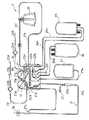
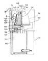
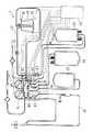
図1は、本発明の血液成分採取装置に使用される血液成分採取回路の構成例を示す平面図であり、図2は、図1の血液成分採取回路のカセットハウジング部分の平面図であり、図3は、血液成分採取回路に使用される遠心分離器に駆動装置が装着された状態の部分破断断面図であり、図4は、血液成分採取回路を装着した状態の本発明の血液成分採取装置の一実施例の概念図である。
本発明の血液成分採取装置1は、内部に貯血空間を有するローター142と、貯血空間に連通する流入口および流出口とを有し、ローター142の回転により流入口より導入された血液を貯血空間内で遠心分離する遠心分離器20と、採血針29もしくは血液プールへの接続部と遠心分離器20の流入口とを接続するための第1のライン21と、遠心分離器20の流出口に接続された第2のライン22と、第1のライン21に接続され、抗凝固剤注入のための第3のライン23と、第1のライン21に接続された第1チューブ25aおよび第2のライン22と接続された第2チューブ25bを有する血漿採取バッグ25と、第2のライン22に接続された血小板採取バッグ26とを備える血液成分採取回路2のための血液成分採取装置である。
【0018】
血液成分採取装置1は、遠心分離器20のローター142を回転させるための遠心分離器駆動装置10と、第1のライン21のための第1の送液ポンプ11と、第3のライン23のための第2の送液ポンプ12と、血液成分採取回路2の流路の開閉を行うための複数の流路開閉手段81,82,83,84,85,86,87と、遠心分離器駆動装置10、第1の送液ポンプ11、第2の送液ポンプ12および複数の流路開閉手段を制御するための制御部13を備える。
【0019】
そこで、最初に血液成分採取回路2について説明する。
この血液成分採取回路2は、血液成分、特に血小板を採取するための回路である。血小板採取回路2は、採血針29のような採血器具、もしくは採血針または血液プール接続部を有する採血器具への接続部(採血器具接続部)、採血針29もしくは採血器具接続部と遠心分離器20の流入口とを接続し、第1のポンプチューブ21gを備える第1のライン21(採血および返血ライン)、遠心分離器20の流出口と第1のライン21とを接続するための第2のライン22、第1のライン21の採血針29の近くに接続され、第2のポンプチューブ23aを備える第3のライン23(抗凝固剤注入ライン)、第1のライン21のポンプチューブ21gより採血針側に接続された第1チューブ25aおよび第2のライン22と接続された第2チューブ25bを有する血漿採取バッグ25、第2のライン22に接続された第3チューブ26aを備える血小板採取バッグ26、第2のライン22に接続された第4チューブ27aを備えるバフィーコート採取バッグ27、第2のライン22に接続された液体(生理食塩水)注入用の第4のライン24を備える。血液成分採取回路2としては、採血針ではなく、血液バッグなどの血液プールに接続するための接続部(例えば、金属もしくは合成樹脂針)でもよい。
【0020】
採血針29として、公知の金属針が使用される。第1のライン21は、採血針29が接続された採血針側第1ライン21aと遠心分離器20の流入口とを接続された遠心分離器側第1ライン21bとからなる。採血針側第1ライン21aは、軟質樹脂製チューブが複数接続されて形成されている。採血針側第1ライン21aは、採血針側より、第3のライン23との接続用分岐コネクター21c、気泡およびマイクロアグリゲート除去のためのチャンバー21d、第2のライン22との接続用分岐コネクター21e、血漿採取バッグ25の第1チューブ25aとの接続用分岐コネクター21fを備える。チャンバー21dには、通気性かつ菌不透過性のフィルター21iが接続されている。遠心分離器側第1ライン21bは、第1チューブ25aとの接続用分岐コネクター21fに接続されており、その付近に形成されたポンプチューブ21gを有する。
【0021】
遠心分離器20の流出口と第1のライン21とを接続する第2のライン22は、一端が遠心分離器20の流出口に接続され、他端が第1のライン21の接続用分岐コネクター21eに接続されている。第2のライン22は、遠心分離器側から、血漿採取バッグ25の第2チューブ25bならびに血小板採取バッグ26の第3チューブとの接続用分岐コネクター22a、第4のライン24との接続用分岐コネクター22b、気泡除去用フィルター22fを備えるチューブとの接続用分岐コネクター22c、バフィーコート採取バッグ27の第4チューブ27aとの接続用分岐コネクター22dを備える。
【0022】
第3のライン23は、一端が第1のライン21に設けられた接続用分岐コネクター21cに接続されている。第3のライン23は、コネクター21c側より、ポンプチューブ23a、異物除去用フィルター23b、気泡除去用チャンバー23c、抗凝固剤容器接続用針23dを備えている。
【0023】
第4のライン24は、一端が第2のライン22の接続用分岐コネクター22bに接続されている。第4のライン24は、コネクター22b側より、異物除去用フィルター24a、生理食塩水容器接続用針24bを備えている。
【0024】
血漿採取バッグ25は、第1のライン21のポンプチューブ21gより採血針側に位置する分岐コネクター21fに接続された第1チューブ25a、第2のライン22の分岐コネクター22aに接続された第2チューブ25bを有する。血小板採取バッグ26は、第2のライン22の分岐コネクター22aに接続された第3チューブ26aを備える。バフィーコート採取バッグ27は、第2のライン22の分岐コネクター22dに接続された第4チューブ27aを備える。
【0025】
上述した第1から第4のライン24の形成に使用されるチューブ、ポンプチューブ、さらに、バッグに接続されているチューブの構成材料としては、例えば、ポリ塩化ビニル、ポリエチレン、ポリプロピレン、PETやPBTのようなポリエステル、エチレンー酢酸ビニル共重合体、ポリウレタン、ポリエステルエラストマー、スチレンーブタジエンースチレン共重合体等の熱可塑性エラストマー等が挙げられるが、その中でも特に、ポリ塩化ビニルが好ましい。各チューブがポリ塩化ビニル製であれば、十分な可撓性、柔軟性が得られるので取り扱いがし易く、また、クレンメ等による閉塞にも適するからである。また、上述した分岐コネクタの構成材料についても、前記チューブの構成材料と同様のものを用いることができる。なお、ポンプチューブとしては、ローラーポンプにより押圧されても損傷を受けない程度の強度を備えるものが使用されている。
【0026】
血漿採取バッグ25、血小板採取バッグ26、バフィーコート採取バッグ27は、それぞれ、樹脂製の可撓性を有するシート材を重ね、その周縁部を融着(熱融着、高周波融着等)または接着して袋状にしたものが使用される。各バッグ25,26,27に使用される材料としては、例えば、軟質ポリ塩化ビニルが好適に使用される。この軟質ポリ塩化ビニルにおける可塑剤としては、例えば、ジ(エチルヘキシル)フタレート(DEHP)、ジ−(n−デシル)フタレート(DnDP)等が使用される。なお、このような可塑剤の含有量は、ポリ塩化ビニル100重量部に対し、30〜70重量部程度とするのが好ましい。
【0027】
また、上記各バッグ25,26,27のシート材料としては、ポリオレフィン、すなわちエチレン、プロピレン、ブタジエン、イソプレン等のオレフィンあるいはジオレフィンを重合または共重合した重合体を用いてもよい。具体的には、例えは、ポリエチレン、ポリプロピレン、エチレン−酢酸ビニル共重合体(EVA)、EVAと各種熱可塑性エラストマーとのポリマーブレンド等、あるいは、これらを任意に組み合せたものが挙げられる。さらには、ポリエチレンテレフタレート(PET)、ポリブチレンテレフタレート(PBT)、ポリ−1,4−シクロヘキサンジメチルテレフタレート(PCHT)のようなポリエステル、ポリ塩化ビニリデンを用いることもできる。
【0028】
なお、血小板採取バッグ26に使用されるシート材としては、血小板保存性を向上するためにガス透過性に優れるものを用いることがより好ましい。そのようなシート材としては、例えば、上述したポリオレフィンやDnDP可塑化ポリ塩化ビニル等を用いること、また、このような素材を用いることなく、上述したような材料のシート材を用い、厚さを比較的薄く(例えば、0.1〜0.5mm程度、特に、0.1〜0.3mm程度)したものが好適である。また、血小板バッグには、例えば、生理食塩水、GAC、PAS、PSM−1のような血小板保存液が予め入れられていてもよい。
【0029】
そして、血液成分採取回路2の主要部分は、図2に示すように、カセット式となっている。血液成分採取回路2は、すべてのライン(第1のライン、第2のライン、第3のライン、第4のライン)およびすべてのチューブ(第1チューブ、第2チューブ、第3チューブ、第4チューブ)を部分的に収納しかつ部分的にそれらを保持し、言い換えれば、部分的にそれらが固定されたカセットハウジング28を備える。カセットハウジング28には、第1のポンプチューブ21gの両端および第2のポンプチューブ23aの両端が固定され、これらポンプチューブ21g,23aは、カセットハウジング28より、ローラーポンプの形状に対応したループ状に突出している。このため、第1および第2のポンプチューブ21g,23aは、ローラポンプへの装着が容易である。
【0030】
さらに、カセットハウジング28は、カセットハウジング28内に位置する複数の開口部を備えている。具体的には、ポンプチューブ21gより採血針側部分の第1のライン21を露出させかつ、血液成分採取装置1の第1の流路開閉手段81の侵入が可能な第1の開口部91、血漿採取バッグ25の第1チューブ25aを露出させかつ血液成分採取装置1の第2の流路開閉手段82の侵入が可能な第2の開口部92、血漿採取バッグ25の第2チューブ25bを露出させかつ血液成分採取装置1の第3の流路開閉手段83の侵入が可能な第3の開口部93、血小板採取バッグ26の第3チューブを露出させかつ血液成分採取装置1の第4の流路開閉手段84の侵入が可能な第4の開口部94、第2のライン22とバフィーコート採取バッグ27の第4チューブ27aとの接続部より遠心分離器側(上流側)の位置の第2のライン22を露出させかつ血液成分採取装置1の第5の流路開閉手段85の侵入が可能な第5の開口部95、第1のライン21との接続部とバフィーコート採取バッグ27の第4チューブ27aとの接続部との間(第2のライン22と第4チューブ27aとの接続部より下流側)の第2のライン22を露出させかつ血液成分採取装置1の第6の流路開閉手段86の侵入が可能な第6の開口部96、第4のライン24を露出させかつ血液成分採取装置1の第7の流路開閉手段87の侵入が可能な第7の開口部97を備えている。
【0031】
また、カセットハウジング28の内面には、上述した分岐コネクターが固定されている。さらに、カセットハウジング28の側面付近には、ハウジングの側面より突出するラインおよびチューブを保持し、かつハウジング部分での折れ曲がりを防止するための補強チューブが設けられている。カセットハウジング28は、内部に図2において波線で示す部分を収納可能な箱状体となっている。そして、カセットハウジング28は、ある程度の剛性を有する合成樹脂により形成されている。
【0032】
血液成分採取装置1は、このカセットハウジング装着部(図示せず)を備えている。このため、カセットハウジング28を血液成分採取装置1のカセットハウジング装着部に装着することにより、カセットハウジング28の開口部より露出する部分の各ラインおよび各チューブが、自動的に対応する流路開閉手段に装着される。これにより回路の装着が容易であるとともに、血液成分採取準備も迅速に行える。また、血液成分採取装置1には、カセットハウジング装着部に近接して2つのポンプが設けられている。このため、カセットハウジング28より露出するポンプチューブのポンプへの装着も容易である。
【0033】
血液成分採取回路2に設けられている遠心分離器20は、通常遠心ボウルと呼ばれており、遠心力により血液成分を分離する。遠心分離器20は、図3に示すように、上端に流入口143が形成された鉛直方向に伸びる管体141と、管体141の回りで回転し、上部145に対し液密にシールされた中空のローター142とで構成されている。ローター142には、その底部および周壁内面に沿って流路(貯血空間)が形成され、この流路の上部に連通するように流出口144が形成されている。この場合、ローター142の容積は、例えば、100〜350ml程度とされる。
【0034】
ローター142は、血液成分採取装置1が備えるロータ回転駆動装置10によりあらかじめ設定された所定の遠心条件(回転速度および回転時間)で回転される。この遠心条件により、ローター142内の血液の分離パターン(例えば、分離する血液成分数)を設定することができる。本実施例では、図3に示すように、血液がローター142の流路内で内層より血漿層131、バフィーコート層132および赤血球層133に分離されるように遠心条件が設定される。
【0035】
次に、図4に示す本発明の血液成分採取装置1について説明する。
血液成分採取装置1は、遠心分離器20のローター142を回転させるための遠心分離器駆動装置10と、第1のライン21のための第1の送液ポンプ11と、第3のライン23のための第2の送液ポンプ12と、血液成分採取回路2の流路の開閉を行うための複数の流路開閉手段81,82,83,84,85,86,87と、遠心分離器駆動装置10、第1の送液ポンプ11、第2の送液ポンプ12および複数の流路開閉手段を制御するための制御部13を備える。さらに、血液成分採取装置1は、第2チューブ25bとの接続部22aより遠心分離器側(上流側)の第2のライン22に装着される濁度センサ14、遠心分離器20の上方に取り付けられた光学式センサ15と、血漿採取バッグ25の重量を検知するための重量センサ16を備える。
【0036】
制御部13は、第1の送液ポンプ11および第2の送液ポンプ12のための2つのポンプコントローラ(図示せず)を備え、制御部13の制御機構と第1の送液ポンプ11および第2の送液ポンプ12とはポンプコントローラを介して電気的に接続されている。遠心分離器駆動装置10が備える駆動コントローラは、制御部13と電気的に接続されている。そして、流路開閉手段81,82,83,84,85,86,87は、すべて制御部13に接続され、それらの開閉は制御部13により制御されている。また、濁度センサ14、遠心分離器20の上方に取り付けられた光学式センサ15、血漿採取バッグ25の重量を検知するための重量センサ16は、制御部13と電気的に接続され、それらより出力される信号は制御部13に入力される。制御部13は、例えばマイクロコンピュータで構成される制御機構を有し、上述した重量センサ16、光学式センサ15、濁度センサ14からの検出信号は、制御部13へ随時入力される。制御部13は、濁度センサ14、光学式センサ15、重量センサ16からの信号に基づき、各ポンプの回転、停止、回転方向(正転/逆転)を制御するとともに、必要に応じ、各流路開閉手段の開閉および遠心分離器回転駆動装置10の作動を制御する。
【0037】
第1の流路開閉手段81は、ポンプチューブ21gより採血針側において第1のライン21を開閉するために設けられている。第2の流路開閉手段82は、血漿採取バッグ25の第1チューブ25aを開閉するために設けられている。第3の流路開閉手段83は、血漿採取バッグ25の第2チューブ25bを開閉するために設けられている。第4の流路開閉手段84は、血小板採取バッグ26の第3チューブを開閉するために設けられている。第5の流路開閉手段85は、第2のライン22とバフィーコート採取バッグ27の第4チューブ27aとの接続部22dより遠心分離器側(上流側)の位置にて、第2のライン22を開閉するために設けられている。第6の流路開閉手段86は、第1のライン21との接続部21eと第4チューブ27aとの接続部との間(第2のライン22と第4チューブ27aとの接続部より下流側)の位置にて、第2のライン22を開閉するために設けられている。第7の流路開閉手段87は、第4のライン24を開閉するために設けられている。流路開閉手段は、ラインもしくはチューブの挿入部を備え、挿入部には、例えば、ソレノイド、電動モーター、シリンダ(油圧または空気圧)等の駆動源で作動するクランプを有する。具体的には、ソレノイドで作動する電磁クランプが好適である。流路開閉手段のクランプは、制御部13からの信号に基づいて作動する。
【0038】
回転駆動装置10は、図3に示すように、遠心分離器20を収納するロータ回転駆動装置ハウジング151と、脚部152と、駆動源であるモータ153と、遠心分離器20を保持する円盤状の固定台155とで構成されている。ハウジング151は、脚部152の上部に載置、固定されている。また、ハウジング151の下面には、ボルト156によりスペーサー157を介してモータ153が固定されている。モータ153の回転軸154の先端部には、固定台155が回転軸154と同軸でかつ一体的に回転するように嵌入されており、固定台155の上部には、ローター142の底部が嵌合する凹部が形成されている。また、遠心分離器20の上部145は、図示しない固定部材によりハウジング151に固定されている。ロータ回転駆動装置10では、モータ153を駆動すると、固定台155およびそれに固定されたローター142が、例えば、回転数3000〜6000rpmで回転する。
【0039】
また、ロータ回転駆動装置ハウジング151の内壁には、遠心分離器内の分離された血液成分の界面(例えば、血漿層131とバフィーコート層132との界面B、バフィーコート層132と赤血球層133との界面)の位置を光学的に検出する光学式センサ15が、取付部材158により設置、固定されている。この光学式センサ15としては、ローター142の外周面に沿って上下方向に走査し得る光学式センサが用いられる。このセンサは、遠心分離器20の肩の部分に向けて光を照射する光源と、遠心ボウルから反射して戻ってくる光を受光する受光部で構成されている。つまり、LEDのような発光素子と受光素子とが列状に配置され、発光素子から発せられた光の血液成分での反射光を受光素子により受光し、その受光光量を光電変換するように構成されている。分離された血液成分(例えば、血漿層131とバフィーコート層132との界面B)により反射光の強度が異なるため、受光光量が変化した受光素子に対応する位置が、界面Bの位置として検出される。より、具体的には、遠心分離器20の光が通過する位置が透明な液体(血漿や水)で充填されている時と、バフィーコート層で充填されている時の、受光部での受光量の差から、バフィーコート層が光通過部に到達したことが検知される。バフィーコート層を検出する位置は、光がボウル内を通過する位置を変えることで調節され、通常は、光線通過位置を決めたら、そこで固定する。
【0040】
濁度センサ14は、第2のライン22中を流れる流体の濁度を検知するためのものであり、濁度に応じた電圧値を出力する。具体的には、濁度が高い時には低電圧値、濁度が低い時には高電圧値を出力する。
【0041】
第1のライン21のポンプチューブ21gが装着される第1の送液ポンプ11ならびに第3のライン23のポンプチューブ23aが装着される第2の送液ポンプ12としては、ローラーポンプ、ペリスタリックポンプなどの非血液接触型ポンプが好適である。また、第1の送液ポンプ11(血液ポンプ)としては、いずれの方向にも血液を送ることができるものが使用される。具体的には、正回転と逆回転が可能なローラーポンプが用いられている。
【0042】
制御部13は、第1の送液ポンプ11、第2の送液ポンプを作動させて抗凝固剤が添加された血液を採取し、遠心分離器駆動装置10を作動させて、血液より血漿採取バッグ25内に所定量の血漿を採取する血漿採取ステップと、この血漿採取ステップ終了後に、採血を一時中断し、遠心分離器駆動装置10を作動させて、血漿採取バッグ内の血漿を遠心分離器20に循環させる血漿循環ステップからなる血漿採取循環ステップを複数回行わせ、上記複数回の血漿採取循環ステップの終了後、第1の送液ポンプ11による血漿循環速度を加速させて、遠心分離器20内より血小板を流出させ血小板を血小板採取バッグ26に採取する血小板採取ステップを行わせ、該血小板採取ステップの終了後、遠心分離器20内の血液を返血する返血ステップを行わせる血小板採取操作が行われるように、遠心分離器駆動装置10、第1の送液ポンプ11、第2の送液ポンプ12および複数の流路開閉手段を制御する。
【0043】
具体的には、第1の送液ポンプ11、第2の送液ポンプ12を作動させて抗凝固剤が添加された血液を採取し、遠心分離器駆動装置10を作動させて、血液より血漿採取バッグ25内に第1の所定量の血漿を採取する第1の血漿採取ステップを行わせ、次に、採血を一時中断し、かつ、遠心分離器駆動装置10を作動させて、第1の血漿採取バッグ内の血漿を遠心分離器20に循環させる第1の血漿循環ステップからなる第1の血漿採取循環ステップを行わせ、次に、第1の送液ポンプ11、第2の送液ポンプ12を作動させて抗凝固剤が添加された血液を採取し、遠心分離器駆動装置10を作動させて血漿採取バッグ25内の血漿量が第1の所定量より多い第2の所定量となるまで血漿を採取する第2の血漿採取ステップと、この第2の血漿採取ステップ終了後に、採血を一時中断し、かつ、遠心分離器駆動装置10を作動させて、血漿採取バッグ25内の血漿を遠心分離器20に循環させる第2の血漿循環ステップとからなる第2の血漿採取循環ステップを行わせるものである。
【0044】
そして、この実施例の血液成分採取装置1の制御部13は、第2の血漿循環ステップの終了後、第3の血漿採取循環ステップを行わせるものとなっている。
第3の血漿採取循環ステップでは、第1の送液ポンプ11、第2の送液ポンプ12を作動させて抗凝固剤が添加された血液を採取し、遠心分離器駆動装置10を作動させて血漿採取バッグ25内の血漿量が第2の所定量より多い第3の所定量となるまで血漿を採取する第3の血漿採取ステップを行わせ、さらに、この第3の血漿採取ステップの終了後、採血を一時中断し、かつ、遠心分離器駆動装置10を作動させて、血漿採取バッグ内の血漿を遠心分離器20に循環させる第3の血漿循環ステップを行う。
さらに、この実施例の血液成分採取装置1の制御部13は、第3の血漿循環ステップの終了後、第4の血漿採取循環ステップを行わせるものとなっている。第4の血漿採取循環ステップでは、第1の送液ポンプ11、第2の送液ポンプ12を作動させて抗凝固剤が添加された血液を採取し、遠心分離器駆動装置10を作動させて血漿採取バッグ25内の血漿量が第3の所定量より多い第4の所定量となるまで血漿を採取する第4の血漿採取ステップを行い、さらに、この第4の血漿採取ステップの終了後、採血を一時中断し、かつ、遠心分離器駆動装置10を作動させて、血漿採取バッグ25内の血漿を遠心分離器20に循環させる第4の血漿循環ステップを行わせるものとなっている。
なお、第2の所定量は第1の所定量より多いが、血漿採取バッグ25内の血漿総量が増加するためであり、第2の血漿採取ステップにより採取される血漿量が第1の血漿採取ステップにより採取される血漿量より多い必要はない。つまり、各血漿採取ステップにおいて採取される血漿は任意の量とすればよい。なお、制御上、第1の所定量、第2の所定量、第3の所定量、第4の所定量を、制御部が記憶しており、これと重量センサにより検知される重量信号とを比較し、血漿採取バッグ内の血漿重量がその所定値に到達したことを検知したときに、各血漿採取ステップが終了するものとなっている。
【0045】
さらに、この実施例の血液成分採取装置1の制御部13は、第4の血漿循環ステップの終了後、第5の血漿採取循環ステップを行わせるものとなっている。第5の血漿採取循環ステップでは、第1の送液ポンプ11、第2の送液ポンプ12を作動させて抗凝固剤が添加された血液を採取し、遠心分離器駆動装置10を作動させて血漿採取バッグ25内に血漿を採取する第5の血漿採取ステップを行い、さらに、この第5の血漿採取ステップの終了後、採血を一時中断し、かつ、遠心分離器駆動装置10を作動させて、血漿採取バッグ25内の血漿を遠心分離器20に循環させる第5の血漿循環ステップを行わせるものとなっている。なお、第5の血漿採取ステップでは、界面センサーで検出するため、血漿バッグの重量検知を行わない。
【0046】
さらに、この実施例の血液成分採取装置1の制御部13は、上述した第1の血漿採取循環ステップから第5の血漿採取循環ステップからなる血小板採取操作が2回以上、具体的には、3回行われるように、遠心分離器駆動装置10、第1の送液ポンプ11、第2の送液ポンプ12および複数の流路開閉手段を制御するものである。
【0047】
さらに、この実施例の血液成分採取装置1の制御部13は、血小板採取ステップ終了後であって、返血ステップ前に、第1の送液ポンプ11による血漿循環速度を血小板採取ステップにおける最終速度よりも高くし、遠心分離器20内よりバフィーコートを流出させバフィーコートをバフィーコート採取バッグ27に採取するバフィーコート採取ステップを行うように制御する。なお、バフィーコート採取ステップは、上記の方法に限定されるものではなく、例えば、第1の送液ポンプ11による血漿循環速度を血小板採取ステップにおける最終速度を維持し、かつ、遠心分離器20のローターの回転速度を下げることによりおこなってもよい。さらに、バフィーコート採取ステップは、第1の送液ポンプによる血漿循環速度を血小板採取ステップにおける最終速度より高くするとともに、遠心分離器のローターの回転速度を下げることにより行ってもよい。
【0048】
そして、バフィーコート採取ステップの終了後、採取されたバフィーコートを次の採血ステップの前に遠心分離器20内に返還するバフィーコート返還ステップを行わせるように、第1の送液ポンプ11および複数の流路開閉手段を制御する。
具体的には、全血に抗凝固剤を所定(全血に対して、1/6〜1/15、具体的には1/10)比率で加え、所定速度(250ml/min以下;好ましくは、150から40ml/min以下、具体的には、60ml/min以下)で第1のライン21を介して遠心分離器20に送り、遠心分離器20を所定回転数(3000〜6000rpm、好ましくは、4700〜4800rpm)で回転させて血液を血漿、バフィーコート、赤血球の各成分に分離し、血漿が遠心分離器20をオーバーフローしたら血漿バッグに採取し、血漿を所定量(10〜150ml、好ましくは、20〜30ml)採取した時点で送血を停止して、血漿を所定条件(採血量よりも大きい速度であり、60〜250ml/minで10〜90sec、具体的には、第1循環が200ml/minx30sec、第2循環以降が120ml/minx30sec)で、第1のライン21および第2のライン22を通して遠心分離器20に戻し、採血が終了するまでの間、血漿が所定量(最後の循環から起算して採血量150ml以下)に達するごとに血漿循環を繰り返し、遠心分離器20のバフィーコートが所定半径(具体的には、30〜40mm)に到達した時に、採血を中断し、血漿を所定条件(60〜250ml/minで10〜90sec,具体的には、120〜140ml/minで30sec)で第1のライン21および第2のライン22を通して遠心分離器20に戻し、所定条件(採血量;0から2500/Hct%[ml]、具体的には、1200〜1400/Hct%[ml])条件で再び抗凝固剤加全血を送血した後、血漿を所定条件で第1および第2のライン22を通して遠心分離器20に戻し、所定条件にて段階的に速度を上昇させて(ステップワイズな加速;0.1〜99ml/min/sec,具体的には、10ml/min/sec)血小板採取速度(60〜250ml/min;実際は200ml/min)に到達させ、遠心分離器20より、流出してきた血小板を血小板採取バッグ26に採取するものである。さらに、この装置では、血小板採取後、血液循環速度を維持(60〜250ml/min、具体的には、200ml/min)し、かつ、遠心分離器20の回転数を下げる(今までの回転数より、100〜300rpm程度下げる、好ましくは、4500〜4600rpmとする)ことにより、流出してきたバフィーコートを採取し、次のサイクルの採血を行う前に、採取したバフィーコートを遠心分離器20に供給するようになっている。なお、バフィーコートの採取は、血小板採取後、血液循環速度を所定速度(血小板採取速度以上、好ましくは、60〜250ml/min、具体的には、205ml/min)に加速する事により行ってもよい。
【0049】
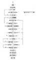
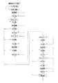
この実施例の血液成分採取装置1による血液成分採取工程(第1回目の血小板採取操作)を図4,図5ないし図10のフローチャートを用いて説明する。この実施例では、血小板採取操作を繰り返して3回行い、さらに、最終回以外の血小板採取ステップ終了後であって、返血ステップ前に、バフィーコート採取ステップを行いかつ次の採血ステップの前に遠心分離器20にこれを返還するバフィーコート返還ステップを行うようになっている。
【0050】
まず、最初に、第3のライン23と採血針29を抗凝固剤でプライミングし、その後ドナーに穿刺針を穿刺する。
そして、図5に示すように、第1の送液ポンプ11、第2の送液ポンプ12を作動させて抗凝固剤が添加された血液を採取し、遠心分離器駆動装置10を作動させて、血液より血漿採取バッグ25内に第1の所定量の血漿を採取する第1の血漿採取ステップを行う。
【0051】
最初の採血が開始されると、血液ポンプ11が所定速度(例えば、60ml/min)で採血を開始する。このとき、抗凝固剤ポンプである第2のポンプも同時に所定速度(例えば、血液ポンプ速度の1/10)で抗凝固剤(例えば、ACD−A液)を供給する。ドナーから採取された血液はACD液と混合され、第1のライン21を流れ、チャンバー、第1の流路開閉手段81を通過し、遠心分離器20に流入する。このとき、第6の流路開閉手段86、第5の流路開閉手段85、第2の流路開閉手段82,第3の流路開閉手段83,第7の流路開閉手段87は閉じており、第1の流路開閉手段81、第4の流路開閉手段84は開いている。遠心分離器20にACD加血液が供給されると、遠心分離器20に入っていた滅菌空気は第2のライン22を流れ、第4の流路開閉手段84を通過し、血小板採取バッグ26内に流入する。採血工程開始と同時に遠心分離器20が所定速度(例えば、4800rpm)で回転を開始し、遠心分離器20は回転しながらACD加血の供給を受けるので、分離器内では血液の遠心分離が行われ、血液は、内側から血漿層、バフィーコート層(BC層)、赤血球層の3層に分離され、分離器の容量を越えるACD加血液(約270ml)が供給されると、遠心分離器20内は完全に血液により満たされ、遠心分離器20出口部から血漿が流出する。遠心分離器20の出口部と接続された第2のライン22に取り付けられた濁度センサ14は、ライン中を流れる流体が、空気から血漿に変わったことを検知し、制御部13は、この濁度センサ14の検知信号に基づき第4の流路開閉手段84を閉塞させ、かつ第3の流路開閉手段83を開放させて、血漿を血漿採取バッグ25内に採取する。血漿採取バッグ25は、その重量が重量センサ16により計測されており、計測された重量信号は制御部13に入力されている。このため、血漿採取バッグ25に採取された血漿重量が第1の所定量(10〜150g、例えば、20g)増加すると、制御部13は、第1の流路開閉手段81を閉塞させ、第2の流路開閉手段82を開放させて、第1の血漿循環ステップに移行する。
【0052】
第1の血漿循環ステップでは、採血を一時中断し、かつ、遠心分離器駆動装置10を作動させて、血漿採取バッグ25内に採取された血漿を遠心分離器20に循環させる。
第1の血漿循環ステップに入ると、制御部13は、第1の流路開閉手段81の閉塞状態および第2の流路開閉手段82の開放状態を維持し、ACDポンプは停止し、血液ポンプ11は所定速度(60〜250ml/min、例えば、200ml/min)で作動し、血漿採取バッグ25の血漿は第2の流路開閉手段82を通って、(例えば4800rpm)の遠心分離器20に送られる。同時に遠心分離器20から流出してきた血漿は濁度センサ14、第3の流路開閉手段83を通って血漿採取バッグ25に流入する。第1の血漿循環ステップが始まって所定時間(10〜90秒、例えば、30秒)が経過すると、制御部13は、第2の流路開閉手段82を閉じ、第1の流路開閉手段81を開いて、第2の血漿採取ステップに移行する。第1の血漿循環は、少なくとも60ml/min以上の流速で、10秒以上行うことが好ましい。
【0053】
第2の血漿採取ステップでは、第1の送液ポンプ11、第2の送液ポンプ12を作動させて抗凝固剤が添加された血液を採取し、遠心分離器駆動装置10を作動させて血漿採取バッグ25内の血漿量が第1の所定量より多い第2の所定量(第1の所定量よりも10〜150g多い)となるまで血漿を採取する。
具体的には、血液ポンプ11が所定速度(例えば、60ml/min)で採血を開始する。このとき、抗凝固剤ポンプである第2のポンプも同時に所定速度(例えば、血液ポンプ速度の1/10)で抗凝固剤(例えば、ACD−A液)を供給する。ドナーから採取された血液はACD液と混合され、所定速度(例えば、4800rpm)で回転する遠心分離器20に流入し、血漿を血漿採取バッグ25内に採取する。血漿採取バッグ25は、その重量が重量センサ16により計測されており、計測された重量信号は制御部13に入力されている。このため、血漿採取バッグ25に採取された血漿重量が第2の所定量(第1の所定量より10〜150g多い、具体的には、第2の所定量=50g)に到達すると、制御部13は、第1の流路開閉手段81を閉塞させ、第2の流路開閉手段82を開放させて、第2の血漿循環ステップに移行する。
【0054】
第2の血漿循環ステップでは、採血を一時中断し、かつ、遠心分離器駆動装置10を作動させて、血漿採取バッグ25内の血漿を遠心分離器20に循環させる。このときの、血液ポンプ速度は所定速度は、第1の血漿循環ステップより遅く、例えば、120ml/minで、約30sec行う。第2の血漿循環は、60〜250ml/minの速度で、10〜90秒行うことが好ましい。また、第2の血漿循環は、少なくとも60ml/min以上の流速で、10秒以上行うことが好ましい。
【0055】
第2の血漿循環ステップの終了後、抗凝固剤が添加された血液を採取し、遠心分離器駆動装置10を作動させて血漿採取バッグ25内の血漿量が第2の所定量より多い第3の所定量(第2の所定量よりも10〜150g多い、具体的には、第3の所定量=80g)となるまで血漿を採取する第3の血漿採取ステップを行う。
【0056】
第3の血漿採取ステップでは、第1の送液ポンプ11が所定速度(例えば、60ml/min)で採血を開始する。このとき、抗凝固剤ポンプである第2のポンプも同時に所定速度(例えば、血液ポンプ速度の1/10)で抗凝固剤(例えば、ACD−A液)を供給する。ドナーから採取された血液はACD液と混合され、所定速度(例えば、4800rpm)で回転する遠心分離器20に流入し、血漿を血漿採取バッグ25内に採取する。血漿採取バッグ25は、その重量が重量センサ16により計測されており、計測された重量信号は制御部13に入力されている。このため、血漿採取バッグ25に採取された血漿重量が第3の所定量に到達すると、制御部13は、第1の流路開閉手段81を閉塞させ、第2の流路開閉手段82を開放させて、第3の血漿循環ステップに移行する。
【0057】
第3の血漿循環ステップでは、採血を一時中断し、かつ、遠心分離器駆動装置10を作動させて、血漿採取バッグ25内の血漿を遠心分離器20に循環させる。このときの、血液ポンプ速度は所定速度は、第1の血漿循環ステップより遅く、例えば、120ml/minで、約30sec行う。第3の血漿循環は、60〜250ml/minの速度で、10〜90秒行うことが好ましい。また、第3の血漿循環は、少なくとも60ml/min以上の流速で、10秒以上行うことが好ましい。
【0058】
次に、第3の血漿循環ステップの終了後、抗凝固剤が添加された血液を採取し、遠心分離器駆動装置10を作動させて血漿採取バッグ25内の血漿量が第3の所定量より多い第4の所定量(第3の所定量よりも10〜150g多い:具体的には、第4の所定量=120g)となるまで血漿を採取する第4の血漿採取ステップを行う。
【0059】
具体的には、第1の送液ポンプ11が所定速度(例えば、60ml/min)で採血を開始する。このとき、抗凝固剤ポンプである第2のポンプも同時に所定速度(例えば、血液ポンプ速度の1/10)で抗凝固剤(例えば、ACD−A液)を供給する。ドナーから採取された血液はACD液と混合され、所定速度(例えば、4800rpm)で回転する遠心分離器20に流入し、血漿を血漿採取バッグ25内に採取する。血漿採取バッグ25は、その重量が重量センサ16により計測されており、計測された重量信号は制御部13に入力されている。このため、血漿採取バッグ25に採取された血漿重量が第4の所定量に到達すると、制御部13は、第1の流路開閉手段81を閉塞させ、第2の流路開閉手段82を開放させて、第4の血漿循環ステップに移行する。
【0060】
第4の血漿循環ステップでは、採血を一時中断し、かつ、遠心分離器駆動装置10を作動させて、血漿採取バッグ25内の血漿を遠心分離器20に循環させる。このときの、血液ポンプ速度は所定速度は、第1の血漿循環ステップより遅く、例えば、120ml/minで、約30sec行う。第4の血漿循環は、60〜250ml/minの速度で、10〜90秒行うことが好ましい。また、第4の血漿循環は、少なくとも60ml/min以上の流速で、10秒以上行うことが好ましい。
【0061】
次に、第4の血漿循環ステップの終了後、抗凝固剤が添加された血液を採取し、遠心分離器駆動装置10を作動させて血漿採取バッグ25内に血漿を採取する第5の血漿採取ステップを行う。具体的には、第1の送液ポンプ11が所定速度(例えば、60ml/min)で採血を開始する。このとき、抗凝固剤ポンプである第2のポンプも同時に所定速度(例えば、血液ポンプ速度の1/10)で抗凝固剤(例えば、ACD−A液)を供給する。ドナーから採取された血液はACD液と混合され、所定速度(例えば、4800rpm)で回転する遠心分離器20に流入し、血漿を血漿採取バッグ25内に採取する。通常、バッグ内の血漿量の増加により、光学式センサ15が、分離器のバフィーコート層を検出すると、この信号が制御部13に送られ、制御部13は、第1の流路開閉手段81を閉塞させ、第2の流路開閉手段82を開放させて、第5の血漿循環ステップに移行する。第5の血漿採取ステップでは、センサがバフィーコート(BC界面:血漿層とバフィーコート層との界面)を検知するまで血漿を採取する。なお、この実施例の装置では、図5、図7および図9のフローチャートにも示されているように、第1から第4の各血漿採取ステップにおいても、BC界面の検知を行っており、もし、これら第1から第4の血漿採取ステップ中にBC界面が検知されると、血漿採取を中断し、第5血漿循環ステップ(このような場合には、第5回ではないので、最終循環ステップ)に移行する。
【0062】
第5の血漿循環ステップ(最終血漿循環ステップ)では、採血を中断し、かつ、遠心分離器駆動装置10を作動させて、血漿採取バッグ内の血漿を遠心分離器20に循環させる。ここでの血液ポンプ速度の所定速度は、例えば、120ml/minで、継続時間は、例えば、30secである。第5の血漿循環は、60〜250ml/minの速度で、10〜90秒行う。第5の血漿循環は、少なくとも60ml/min以上の流速で、10秒以上行うことが好ましい。この循環ステップ終了後、図6の▲1▼に移行し、界面調整用の採血ステップを行う。
【0063】
図6に示すように、界面調整用の採血ステップは、少量血漿採取ステップともいえる。このステップでは、後に行う血小板採取工程でのバフィーコート層の位置をドナーによらず一定にするために、所定の赤血球供給量分だけ採血する。赤血球供給量は採血量をドナーのヘマトクリット値で除した値で定義され、採血量は、12ml程度が一般的である。この採血においても、第1の送液ポンプ11が所定速度(例えば、60ml/min)で採血を開始する。このとき、抗凝固剤ポンプである第2のポンプも同時に所定速度(例えば、血液ポンプ速度の1/10)で抗凝固剤(例えば、ACD−A液)を供給する。ドナーから採取された血液はACD液と混合され、所定速度(例えば、4800rpm)で回転する遠心分離器20に流入され、少量の血漿採取が行われる。制御部13は、設定採取量とポンプ速度より採取時間を演算し、採取時間を経過したときに、採血を終了させる。そして、制御部13は、第1の流路開閉手段81を閉塞させ、第2の流路開閉手段82を開放させて、血小板採取ステップに移行する。
【0064】
上記ステップの終了後、第1の送液ポンプ11による血漿循環速度を加速させて、遠心分離器20内より血小板を流出させ血小板を血小板採取バッグ26に採取する血小板採取ステップを行う。血小板採取ステップは、いわゆる加速工程とも呼ばれる。このステップでは、血液ポンプ速度が、第4の循環ステップと同じ速度から200ml/minまで、所定時間(例えば、1秒間)毎に10ml/minずつ加速するように、制御部13は血液ポンプを操作し、200ml/minに到達したら、血小板採取工程が終了するまで、その速度を維持する。
【0065】
血小板採取ステップが始まると、濁度センサ14が通過する液の濁度を検知し、濁度はセンサにより電圧値として出力され、出力された信号は、制御部13に入力される。血液ポンプの速度が上昇し、おおよそ160から200ml/minに達した時点で遠心分離器20にとどまっていたバフィーコート層に含まれる血小板が流出する。血小板が流出すると濁度センサ14部分を通過する液の濁度が大きくなり、センサより出力される電圧値が0.2V低下した時点で第3の流路開閉手段83が閉じて第4の流路開閉手段84が開き、遠心分離器20から流出してくる血小板リッチな血漿を血小板採取バッグ26に採取する。濁度センサ14から出力される電圧値は、制御部13により血小板濃度に換算され、血小板採取中の血小板採取バッグ26の血小板濃度を演算する。血小板採取バッグ26の血小板濃度は一旦最高濃度に到達したのち、濃度が低下する。最高濃度に到達したことを検知した時点において、血小板採取ステップは終了し、バフィーコート採取ステップに移行する。
【0066】
バフィーコート採取ステップでは、上述の血小板採取ステップが終了すると、制御部13は、第4の流路開閉手段84を閉じ、第5の流路開閉手段85を開放させる。血漿採取バッグ25内の血漿は、血液ポンプ11により、遠心分離器20に送られ、同時に遠心分離器20から流出した液(バフィーコート層が流出したもの)は、バフィーコート採取バッグ27に流入する。バフィーコート採取ステップでは、血液ポンプ速度が血小板採取ステップにおける最終速度のまま維持され、かつ、遠心分離器の回転速度が4600rpmに下げられ、これにより、遠心分離器20内よりバフィーコートを流出させバフィーコート採取バッグ27に採取する。ドナーのヘマトクリット値と血小板採取量から演算された量を採取した時点で、血液ポンプ11は停止し、全バルブが閉じ、遠心分離器20の回転が停止してバフィーコート採取ステップが終了する。
次に、遠心分離器20内の血液を返血する返血ステップを行う。制御部13は、血液ポンプ11を逆回転させ、また、第1の流路開閉手段81を開放し、遠心分離器20内に残った赤血球層を、第1のライン21よりドナーに返血する。
これにより、1回(初回)の血小板採取操作が終了する。
【0067】
続いて、図7に示す、2回目の血小板採取操作に移行する。
最初に、図7に示すように、第1回の血小板採取ステップにより採取されたバフィーコートを次の採血ステップの前に遠心分離器20内に返還するバフィーコート返還ステップが行われる。バフィーコート返還ステップに移行すると、制御部13は、遠心分離器20を所定回転数(例えば、4800rpm)で回転させ、第5の流路開閉手段85、第4の流路開閉手段84を開放し、血液ポンプ11を所定速度(デフォルトは100ml/min)で作動させる。バフィーコート採取バッグ27に入っているバフィーコートは、第5の流路開閉手段85を通り、遠心分離器20に供給される。遠心分離器20の空気は、第2のライン22、第4の流路開閉手段84を通って血小板採取バッグ26に送られる。バフィーコート採取量分だけ血液ポンプ11が回転した後、バフィーコート返還ステップは終了する。
【0068】
そして、上述した第1の血漿採取ステップ、第1の血漿循環ステップ、第2の血漿採取ステップ、第2の血漿循環ステップ、第3の血漿採取ステップ、第3の血漿循環ステップ、第4の血漿採取ステップ、第4の血漿循環ステップ、第5の血漿採取ステップ、第5の血漿循環ステップ、終了後図8に示す▲2▼に移行し、界面調整用の採血ステップ、血小板採取ステップ、バフィーコート採取ステップ、返血ステップを順次行い、2回目の血小板採取操作が終了する。
【0069】
次に、図9に示す、最終回の血小板採取操作について説明する。なお、この実施例では、3回目が最終回となっているが、これに限らず、4回目以降が最終回の血小板採取操作となるものでもよい。この場合、最終回以外は、2回目の血小板採取操作(図7および図8)と同じである。
最初に、図9に示すように、第2回の血小板採取操作により採取されたバフィーコートを次の採血ステップの前に遠心分離器20内に返還するバフィーコート返還ステップを行う。
バフィーコート返還ステップに以降すると、制御部13は、遠心分離器20を所定回転数(例えば、4800rpm)で回転させ、第5の流路開閉手段85、第4の流路開閉手段84を開放し、血液ポンプ11を所定速度(デフォルトは100ml/min)で作動させる。バフィーコート採取バッグ27に入っているバフィーコートは、第5の流路開閉手段85を通り、遠心分離器20に供給される。遠心分離器20の空気は、第2のライン22、第4の流路開閉手段84を通って血小板採取バッグ26に送られる。バフィーコート採取量分だけ血液ポンプ11が回転した後、バフィーコート返還ステップは終了する。
【0070】
次に、第1の送液ポンプ11、第2の送液ポンプ12を作動させて抗凝固剤が添加された血液を採取し、遠心分離器駆動装置10を作動させて、血液より血漿採取バッグ25内に第1の所定量の血漿を採取する第1の血漿採取ステップを行う。
【0071】
最初の採血が開始されると、第1の送液ポンプ11が所定速度(例えば、60ml/min)で採血を開始する。このとき、抗凝固剤ポンプである第2のポンプも同時に所定速度(例えば、血液ポンプ速度の1/10)で抗凝固剤(例えば、ACD−A液)を供給する。ドナーから採取された血液はACD液と混合され、第1のライン21を流れ、チャンバー、第1の流路開閉手段81を通過し、遠心分離器20に流入する。このとき、第6の流路開閉手段86、第5の流路開閉手段85、第2の流路開閉手段82,第3の流路開閉手段83,第7の流路開閉手段87は閉じており、第1の流路開閉手段81、第5の流路開閉手段85は開いており、遠心分離器20にACD加血液が供給されると、元々遠心分離器20に入っていた滅菌空気はラインセンサ、第5の流路開閉手段85を通ってバフィーコート採取バッグ27に流入する。採血工程開始と同時に遠心分離器20が所定速度(例えば、4800rpm)で回転を開始し、遠心分離器20は回転しながらACD加血の供給を受けるので、分離器内では血液の遠心分離が行われ、血液は、内側から血漿層、バフィーコート層(BC層)、赤血球層の3層に分離され、分離器の容量を越えるACD加血液(約270ml)が供給されると、遠心分離器20内は完全に血液により満たされ、遠心分離器20出口部から血漿が流出する。遠心分離器20の出口部と接続された第2のライン22に取り付けられた濁度センサ14は、ライン中を流れる流体が、空気から血漿に変わったことを検知し、制御部13は、この濁度センサ14の検知信号に基づき、第5の流路開閉手段85を閉塞させ、かつ第3の流路開閉手段83を開放させて、血漿を血漿採取バッグ25内に採取する。血漿採取バッグ25は、その重量が重量センサ16により計測されており、計測された重量信号は制御部13に入力されている。このため、血漿採取バッグ25に採取された血漿重量が所定量(例えば、20g)増加すると、制御部13は、第1の流路開閉手段81を閉塞させ、第2の流路開閉手段82を開放させて、第1の血漿循環ステップに移行する。
【0072】
そして、上述した第1の血漿循環ステップ、第2の血漿採取ステップ、第2の血漿循環ステップ、第3の血漿採取ステップ、第3の血漿循環ステップ、第4の血漿採取ステップ、第4の血漿循環ステップ、第5の血漿採取ステップ、第5の血漿循環ステップを行い、図10に示す▲3▼に移行し、界面調整用の採血ステップ、血小板採取ステップ、返血ステップを順次行い、最終回の血小板採取操作が終了する。最終回と2回目との相違は、上述した第1の血漿循環ステップにおける空気を流入させるバッグが相違する点と、最終回では、バフィーコート採取ステップを行うことなく返血ステップを行う点である。
【0073】
粒子懸濁液では,粒子濃度が高くなるにつれて懸濁液の見かけ粘度が高くなることが知られている。粘度が高くなると,異なる比重をもつ粒子間の沈降速度差が小さくなる。これを血小板採取工程にあてはめると、遠心分離器20内での粘度が高くなると、血小板と一緒に血小板より比重の大きい白血球が流出する確率が上昇することになる。また、採血中遠心分離器20は回転しており,遠心分離器20内の血液成分には常に遠心力がかかっており、遠心分離器20内の各血液成分は遠心力によって濃縮が進み、分離器の外側より、図3に示すように血球層、バフィーコート層、血漿層に分離される。そして、各層中の粒子は、外側から順次小さいものとなっている。
【0074】
遠心分離器20内には、いわゆる複数のケーキ層が形成され、このケーキ層が徐々に圧縮される。そして、新たに流入する全血は、遠心分離器20の最外層の血球により形成されたケーキ層より流入し、血球はこのケーキ層により捕捉され他の成分は通過し、バフィーコート層、血漿層に移行する。しかし、血球ケーキ層、バフィーコートケーキ層が過剰に圧縮されると各層内の微粒子間の隙間が小さくなり、血小板が、血球ケーキ層もしくはバフィーコートケーキ層に捕捉されることが起きる。このため、血小板の採取効率が低下するものと予想する。
【0075】
しかし、本発明では、血漿採取ステップを複数回に区分し、一回血漿採取ステップ時間を短くできるため、上述のケーキ層の圧縮の進行が少ない上に、複数の血漿循環工程を備えている。このため、血球成分を含まない血漿成分のみが遠心分離器20に流入され、血漿成分は血球ケーキ層およびバフィーコートケーキ層を短時間に通過するため、血球ケーキ層およびバフィーコートケーキ層を膨潤させるため、もしケーキ層の圧縮が生じていてもこれが解消されるものと予想する。これにより、血球ケーキ層、バフィーコートケーキ層の過剰圧縮が抑制され、血小板が、血球ケーキ層もしくはバフィーコートケーキ層に捕捉されることを減少させるものと考える。
【0076】
【実施例】
図4に示すような回路構成で、ACDポンプと血液ポンプ11の2台で構成される装置を作成し、血小板採取性能を比較した。ドナーは同じドナーを用い、2週間以上間隔を開けて比較実験を行った。以下に評価した動作フローを比較したものを示した。n=2例で比較した。得られた濃厚血小板血漿の血小板数、白血球数をSysmex(R)NE−6000で測定した。但し、SysmexのWBC測定下限は0.1X10²[Cells/muL]なので、測定下限を下回ったサンプルではNageotte[1:9]法を用いて側定した。血小板採取量は40mlとした。
【0077】
(実施例)
血小板採取操作は、3回とし、上述の方法により行った。なお、採血速度は、60ml/min、血漿総量が20gとなった後に行う第1循環条件(200ml/min,30sec)、血漿総量が50gとなった後に行う第2循環条件(120ml/min,30sec)、血漿総量が80gとなった後に行う第3循環循環(120ml/min,30sec)、光学式センサがバフィーコート層検出後に行う第4循環条件(120ml/min,30sec)、血小板採取時の加速条件(10ml/min/sec)、血小板採取速度(200ml/min,血小板採取所定濃度まで)、バフィーコート採取速度(205ml/min,40ml)とし、2回目および3回目は、採血前にバフィーコートを遠心分離器に返還し、3回目には、バフィーコート採取を行わなかった。
【0078】
(比較例)
装置としては、実施例と同じものを用いた。血小板採取操作は、3回とし、各条件は、以下のようにした。採血速度は、60ml/min、光学式センサがバフィーコート層検出後に、第1の循環(120ml/min,3sec)と第2の循環(75ml/min,27sec)行い、血小板採取時の加速条件(8ml/min/sec)、血小板採取(血小板最高濃度の50%まで)とした。
そして、採取された実施例および比較例の濃厚血小板血漿の血小板濃度、白血球濃度は以下の通りである。
【0079】
【表1】
【表2】
【発明の効果】
本発明の血液成分採取装置では、1回の血小板採取操作中に、採血を一時中止しそして採取された血漿を遠心分離器に再循環する血漿再循環ステップが少なくとも、2回行われるので、遠心分離器内での血球層、バフィーコート層が過剰圧縮されることを抑制し、白血球の混入が少なく、かつ血小板の採取効率も高い血小板含有液(濃厚血小板血漿)を得ることができる。
【図面の簡単な説明】
【図1】図1は、本発明の血液成分採取装置に使用される血液成分採取回路の構成例を示す平面図である。
【図2】図2は、図1の血液成分採取回路のカセットハウジング部分の平面図である。
【図3】図3は、血液成分採取回路に使用される遠心分離器に駆動装置が装着された状態の部分破断断面図である。
【図4】図4は、血液成分採取回路を装着した状態の本発明の血液成分採取装置の一実施例の概念図である。
【図5】図5は、本発明の血液成分採取装置の作用を説明するためのフローチャートである。
【図6】図6は、本発明の血液成分採取装置の作用を説明するためのフローチャートである。
【図7】図7は、本発明の血液成分採取装置の作用を説明するためのフローチャートである。
【図8】図8は、本発明の血液成分採取装置の作用を説明するためのフローチャートである。
【図9】図9は、本発明の血液成分採取装置の作用を説明するためのフローチャートである。
【図10】図10は、本発明の血液成分採取装置の作用を説明するためのフローチャートである。
【符号の説明】
1 血液成分採取装置
2 血液成分採取回路
10 遠心分離器駆動装置
11 第1の送液ポンプ
12 第2の送液ポンプ
13 制御部
14 濁度センサ
15 光学式センサ
16 重量センサ
20 遠心分離器
21 第1のライン
22 第2のライン
23 第3のライン
24 第4のライン
25 血漿採取バッグ
26 血小板採取バッグ
29 採血針[0001]
BACKGROUND OF THE INVENTION
The present invention relates to a blood component collection device and a blood component collection circuit for separating a predetermined blood component from blood.
[0002]
[Prior art]
At the time of blood collection, for the purpose of effective use of blood and reduction of burden on blood donors, the blood sample is separated into each blood component by centrifugation, etc., and only the components necessary for the transfuser are collected. Ingredients are collected to return the ingredients to the blood donor.
In such component blood collection, when obtaining a platelet preparation, blood collected from a blood donor is introduced into a blood component collection circuit, and a centrifuge called a centrifuge bowl installed in the blood component collection circuit is used to collect plasma, white blood cells, The platelets and red blood cells are separated into four components, and the platelets are collected in a container to obtain a platelet preparation, and the remaining plasma, white blood cells and red blood cells are returned to the blood donor.
[0003]
As a method for collecting platelets, for example, it is disclosed in JP-T-8-509403.TheThere is a method. In Japanese Patent Publication No. 8-509403, the first method is to add a liquid to whole blood at a predetermined flow rate and send it to a centrifuge bowl while diluting. The whole blood is sent to the centrifuge bowl and centrifuged to obtain a low density component. After separating the medium-density component and the high-density component and taking out the low-density component into the first container, the circuit is switched to circulate the low-density component at the first flow rate (constant speed), and the inside of the centrifuge bowl. A second method is disclosed in which the medium density component is taken out while the density component region is expanded and recirculated at the second flow rate (acceleration).
[0004]
[Problems to be solved by the invention]
However, in the first method, three pumps, that is, an ACD pump, a blood collection pump, and a circulation pump are required, and the apparatus becomes large. In the second method, platelets can be collected by two pumps, and the apparatus can be miniaturized. However, there is much contamination of leukocytes in the collected platelets. As a platelet-containing solution for a platelet preparation, a solution containing less leukocytes is required.
Therefore, an object of the present invention is to provide a blood component collection device that can reduce the size of the device, has little white blood cell contamination, has high platelet collection efficiency, and can obtain a high-concentration platelet-containing solution.
[0005]
[Means for Solving the Problems]
To achieve the above purpose,It is as follows.
(1) A rotor having a blood storage space inside, and an inlet and an outlet communicating with the blood storage space, and blood introduced from the inlet by the rotation of the rotor is centrifuged in the blood storage space. A centrifuge, a first line connected to a blood collection needle or blood collection device connection and an inlet of the centrifuge, a second line connected to an outlet of the centrifuge, and the first A blood component collection device comprising a blood component collection circuit having a plasma collection bag connected to one line and the second line, and a platelet collection bag connected to the second line, wherein the blood The component collection device includes a centrifuge drive device for rotating the rotor of the centrifuge, a first liquid feed pump mounted on a first line of the blood component collection circuit, and a blood component collection circuit. Flow path A plurality of flow path opening / closing means for opening and closing; and a control unit for controlling the centrifuge drive device, the first liquid feeding pump, and the flow path opening / closing means, the control unit configured to collect blood collected from a donor A plasma collection step for flowing into the blood storage space of the centrifuge, separating plasma from the blood and collecting it in the plasma collection bag, and after completion of the plasma collection step, blood collection is temporarily suspended, and the plasma in the plasma collection bag A plasma circulation step comprising circulating a plasma between the plasma collection bag and the centrifuge, and a first plasma collection step in the plasma collection and circulation step comprises: Until a predetermined amount of plasma is collected in the plasma collection bag, and after completion of the plurality of plasma collection circulation steps, the plasma circulation rate is accelerated, The centrifuge drive device, the first liquid feeding pump, and the flow are performed so as to perform a platelet collection operation for causing platelets to flow out from the heart separator and collecting platelets in the platelet collection bag. A blood component collecting device for controlling the path opening and closing means.
(2) The control unit includes the centrifuge driving device and the first liquid feeding pump so that a blood return step of returning the blood in the centrifuge is performed after the completion of the platelet collection step. And the blood component collecting device according to (1), which controls the flow path opening / closing means.
(3) The control unit, after the completion of the plurality of plasma collection and circulation steps, before the platelet collection step, flows blood into the blood storage space of the centrifuge and uses blood collected from a donor. (1) or (2) controlling the first liquid feeding pump and the flow path opening / closing means so as to perform a platelet collecting operation for performing a plasma collecting step of separating plasma and collecting it in the plasma collecting bag. The blood component collection device described.
(4) The blood component collection device according to any one of (1) to (3), wherein the control unit includes a weight sensor that detects a weight of the plasma collection bag.
(5) The blood component collection device further includes a sensor that detects a position of an interface of the separated blood component in the rotor of the centrifuge, and the control unit further converts a signal from the sensor into a signal. The blood component collection device according to any one of (1) to (4), wherein the first liquid feed pump and the flow path opening / closing means are controlled so as to end the plasma collection step.
(6) The control unit controls the centrifuge drive device, the first liquid feeding pump, and the flow path opening / closing means so that the platelet collection operation is performed at least twice (1) to (5). The blood component collection device according to any one of the above.
(7)A centrifuge having a rotor having a blood storage space therein, an inlet and an outlet communicating with the blood storage space, and centrifuging blood introduced from the inlet by rotation of the rotor in the blood storage space A first line for connecting a blood collection needle or blood collection instrument connection part and the inlet of the centrifuge, a second line connected to the outlet of the centrifuge, and the first Connected to the lineTheA third line for injecting an anticoagulant and said first line;On the wayA plasma collection bag having a first tube connected to the second line and a second tube connected to the second line; and a platelet collection bag connected to the second line;Consist ofA blood component collection device for a blood component collection circuit, the blood component collection device comprising: a centrifuge drive device for rotating the rotor of the centrifuge; the first line; and the first line. A first liquid delivery pump for the first line, a second liquid delivery pump for the third line, and the blood component collection. Controlling a plurality of channel opening / closing means for opening / closing a circuit channel, the centrifuge drive device, the first liquid feeding pump, the second liquid feeding pump, and the plurality of channel opening / closing means A control unit for operating the first liquid feeding pump and the second liquid feeding pump to collect blood to which an anticoagulant has been added, and the centrifuge drive device Blood that is activated to collect plasma from the blood into the plasma collection bag After the collection step and the plasma collection step, the blood collection is temporarily interrupted, and the centrifuge driving device is operated to circulate the plasma in the plasma collection bag to the centrifuge. Make the step multiple timesAnd the first plasma collection step in the plasma collection and circulation step is performed until the plasma collection bag collects a predetermined amount of plasma,After completion of the plurality of plasma collection and circulation steps, the platelet collection step of accelerating the plasma circulation rate by the first liquid feeding pump and allowing platelets to flow out of the centrifuge and collecting platelets in the platelet collection bag After the completion of the platelet collection step, the centrifuge drive device and the first feed are performed so that a platelet collection operation for performing a blood return step for returning the blood in the centrifuge is performed. A blood component collecting device for controlling a liquid pump, the second liquid feeding pump, and the plurality of flow path opening / closing means.
[0006]
And it is preferable that the said control part is what makes the said plasma collection circulation step at least 3 times. Further, the control unit is configured to perform the first liquid feeding pump, the second liquid feeding pump, the second liquid feeding pump, the second liquid feeding pump, and the second liquid feeding pump after accelerating the plasma circulation rate by the first liquid feeding pump. The blood collection pump is operated to collect blood to which an anticoagulant has been added, and the centrifuge drive device to operate to collect a predetermined amount of plasma from the blood into the plasma collection bag. It is preferable that
[0007]
Further, the control unit operates the first liquid supply pump and the second liquid supply pump to collect blood to which an anticoagulant is added, operates the centrifuge drive device, A first plasma collection step for collecting a first predetermined amount of plasma in the plasma collection bag; and after the completion of the first plasma collection step, blood collection is temporarily interrupted and the centrifuge drive device is operated. A first plasma collection and circulation step comprising a first plasma circulation step of circulating the plasma in the plasma collection bag to the centrifuge, and then the first liquid feeding pump, The blood supply pump is operated to collect blood to which an anticoagulant is added, and the centrifuge driving device is operated to increase the amount of plasma in the plasma collection bag from the second predetermined amount. Second plasma collection to collect plasma until a predetermined amount of And after the completion of the second plasma collection step, the blood collection is temporarily interrupted, and the centrifuge driving device is operated to circulate the plasma in the plasma collection bag to the centrifuge. A second plasma collection and circulation step including a plasma circulation step may be performed.
[0008]
In addition, the control unit, after the end of the second plasma collection and circulation step, collects blood to which an anticoagulant is added by operating the first liquid feeding pump and the second liquid feeding pump, A third plasma collecting step of collecting plasma until the plasma amount in the plasma collection bag becomes a third predetermined amount greater than the second predetermined amount by operating a centrifuge drive device; After completion of the plasma collection step, a third plasma circulation step is provided which comprises a third plasma circulation step in which the blood collection is temporarily interrupted and the centrifuge driving device is operated to circulate the plasma in the plasma collection bag to the centrifuge. It is preferable to perform 3 plasma collection and circulation steps.
[0009]
Further, the control unit, after the completion of the third plasma collection and circulation step, collects blood to which an anticoagulant is added by operating the first liquid feeding pump and the second liquid feeding pump, A fourth plasma collection step for collecting plasma until the plasma amount in the plasma collection bag reaches a fourth predetermined amount greater than the third predetermined amount by operating a centrifuge drive device; After completion of the plasma collection step, a fourth plasma circulation step is provided, which comprises a fourth plasma circulation step in which blood collection is temporarily interrupted and the centrifuge drive device is operated to circulate the plasma in the plasma collection bag to the centrifuge. It is preferable to perform 4 plasma collection and circulation steps.
[0010]
In addition, after the end of the fourth plasma collection and circulation step, the control unit operates the first liquid feeding pump and the second liquid feeding pump to collect blood to which an anticoagulant is added, and A fifth plasma collecting step of collecting the plasma in the plasma collecting bag by operating the centrifuge driving device; and after completion of the fifth plasma collecting step, blood collection is temporarily interrupted, and the centrifuge driving It is preferable that the apparatus is operated to perform a fifth plasma collection and circulation step including a fifth plasma circulation step for circulating the plasma in the plasma collection bag to the centrifuge.
[0011]
The blood component collection device preferably includes a weight sensor for the plasma collection bag. Further, the control unit includes the centrifuge driving device, the first liquid feeding pump, the second liquid feeding pump, and the plurality of flow path opening / closing means so that the platelet collecting operation is performed at least twice. It is preferable to control the above.
[0012]
In addition, the blood component collection circuit includes, for example, a buffy coat collection bag connected to the second line, and the control unit is after the platelet collection step and before the blood return step, A buffy coat collecting step is performed in which the plasma circulation rate by the first liquid feeding pump is made higher than the final rate in the platelet collecting step, the buffy coat is discharged from the centrifuge and the buffy coat is collected in the buffy coat bag. It may be a thing.
[0013]
In addition, the blood component collection circuit includes, for example, a buffy coat collection bag connected to the second line, and the control unit is after the platelet collection step and before the blood return step, The plasma circulation speed by the first liquid feeding pump is made equal to or higher than the final speed in the platelet collecting step, and the rotation speed of the centrifuge rotor is lowered to allow the buffy coat to flow out from the centrifuge. A buffy coat collecting step for collecting the coat in the buffy coat bag may be performed.
[0014]
Further, the control unit returns the collected buffy coat into the centrifuge before the next blood collecting step when a platelet collecting operation is further performed after the end of the buffy coat collecting step. It is preferable to control the first liquid feeding pump and the plurality of flow path opening / closing means so as to perform the step.
[0017]
DETAILED DESCRIPTION OF THE INVENTION
The blood component collection device of the present invention will be described with reference to the embodiments shown in the drawings.
FIG. 1 is a plan view showing a configuration example of a blood component collection circuit used in the blood component collection device of the present invention. FIG. 2 is a plan view of a cassette housing portion of the blood component collection circuit of FIG. FIG. 3 is a partially broken cross-sectional view of a centrifuge used in a blood component collection circuit in a state where a drive device is mounted, and FIG. 4 is a blood component collection of the present invention in a state where the blood component collection circuit is mounted. It is a conceptual diagram of one Example of an apparatus.
The blood
[0018]
The blood
[0019]
First, the blood component collection circuit 2 will be described.
The blood component collection circuit 2 is a circuit for collecting blood components, particularly platelets. The platelet collection circuit 2 includes a blood collection device such as a
[0020]
A known metal needle is used as the
[0021]
The
[0022]
One end of the
[0023]
One end of the
[0024]
The
[0025]
As a constituent material of the tube used for forming the first to
[0026]
Each of the
[0027]
Further, as the sheet material of each of the
[0028]
In addition, plateletsCollectionAs the sheet material used for the
[0029]
The main part of the blood component collection circuit 2 is a cassette type as shown in FIG. The blood component collection circuit 2 includes all lines (first line, second line, third line, fourth line) and all tubes (first tube, second tube, third tube, fourth line). Tube) is partially housed and partially retained, in other words, it comprises a
[0030]
Furthermore, the
[0031]
Also,MosquitoThe branch connector described above is fixed to the inner surface of the set
[0032]
The blood component collection device 1MosquitoA set housing mounting portion (not shown) is provided. For this reason,MosquitoBy mounting the set
[0033]
The
[0034]
The
[0035]
Next, the blood
The blood
[0036]
The
[0037]
The first flow path opening / closing means 81 is provided to open and close the
[0038]
As shown in FIG. 3, the
[0039]
In addition, on the inner wall of the rotor rotation
[0040]
The turbidity sensor 14 is for detecting the turbidity of the fluid flowing in the
[0041]
The first
[0042]
The
[0043]
Specifically, the first
[0044]
And the
In the third plasma collection and circulation step, the first
Furthermore, the
The second predetermined amount is larger than the first predetermined amount because the total amount of plasma in the
[0045]
Further, the
[0046]
Furthermore, the
[0047]
Furthermore, the
[0048]
Then, after the buffy coat collecting step is completed, the first
Specifically, an anticoagulant is added to whole blood at a predetermined ratio (1/6 to 1/15, specifically 1/10 with respect to whole blood), and a predetermined rate (250ml / min or less; preferably 150To 40 ml / min or less, specifically, 60 ml / min or less) to the
[0049]
The blood component collection process (first platelet collection operation) by the blood
[0050]
First, the
Then, as shown in FIG. 5, the first
[0051]
When the first blood collection is started, the
[0052]
In the first plasma circulation step, blood collection is temporarily interrupted, and the
When entering the first plasma circulation step, the
[0053]
In the second plasma collection step, the first
Specifically, the
[0054]
In the second plasma circulation step, blood collection is temporarily interrupted, and the
[0055]
After the completion of the second plasma circulation step, blood to which an anticoagulant is added is collected, the
[0056]
In the third plasma collection step, the first liquid feeding pump 11 starts blood collection at a predetermined speed (for example, 60 ml / min). At this time, the second pump, which is an anticoagulant pump, also supplies an anticoagulant (for example, ACD-A solution) at a predetermined speed (for example, 1/10 of the blood pump speed). The blood collected from the donor is mixed with the ACD solution, flows into the
[0057]
In the third plasma circulation step, blood collection is temporarily interrupted, and the
[0058]
Next, after the completion of the third plasma circulation step, blood to which an anticoagulant is added is collected, and the
[0059]
Specifically, the first liquid feeding pump 11 starts blood collection at a predetermined speed (for example, 60 ml / min). At this time, the second pump, which is an anticoagulant pump, also supplies an anticoagulant (for example, ACD-A solution) at a predetermined speed (for example, 1/10 of the blood pump speed). The blood collected from the donor is mixed with the ACD solution, flows into the
[0060]
In the fourth plasma circulation step, blood collection is temporarily interrupted, and the
[0061]
Next, after the completion of the fourth plasma circulation step, the blood to which the anticoagulant is added is collected, and the fifth plasma collection for collecting the plasma in the
[0062]
In the fifth plasma circulation step (final plasma circulation step), blood collection is interrupted, and the
[0063]
As shown in FIG. 6, the blood collection step for interface adjustment can be said to be a small-scale plasma collection step. In this step, blood is collected by a predetermined amount of supplied red blood cells so that the position of the buffy coat layer in the subsequent platelet collection step is constant regardless of the donor. The amount of red blood cells supplied is defined as a value obtained by dividing the amount of blood collected by the donor's hematocrit value, and the amount of blood collected is generally about 12 ml. Also in this blood collection, the first liquid feeding pump 11 starts blood collection at a predetermined speed (for example, 60 ml / min). At this time, the second pump, which is an anticoagulant pump, also supplies an anticoagulant (for example, ACD-A solution) at a predetermined speed (for example, 1/10 of the blood pump speed). The blood collected from the donor is mixed with the ACD solution and flows into the
[0064]
After completion of the above steps, a platelet collection step is performed in which the plasma circulation rate by the first
[0065]
When the platelet collection step is started, the turbidity of the liquid passing through the turbidity sensor 14 is detected, the turbidity is output as a voltage value by the sensor, and the output signal is input to the
[0066]
In the buffy coat collection step, when the above-described platelet collection step ends, the
Next, a blood return step for returning the blood in the
Thereby, one (first) platelet collection operation is completed.
[0067]
Subsequently, the process proceeds to the second platelet collection operation shown in FIG.
First, as shown in FIG. 7, a buffy coat returning step is performed in which the buffy coat collected in the first platelet collecting step is returned to the
[0068]
The first plasma collection step, the first plasma circulation step, the second plasma collection step, the second plasma circulation step, the third plasma collection step, the third plasma circulation step, and the fourth plasma described above. After completion of the collection step, the fourth plasma circulation step, the fifth plasma collection step, the fifth plasma circulation step, the process proceeds to (2) shown in FIG. 8, and the blood collection step for adjusting the interface, platelet collection step, buffy coat The collection step and the blood return step are sequentially performed, and the second platelet collection operation is completed.
[0069]
Next, the final platelet collection operation shown in FIG. 9 will be described. In this embodiment, the third round is the final round. However, the present invention is not limited to this, and the fourth round or later may be the final platelet collection operation. In this case, except for the final round, the second platelet collection operation (FIGS. 7 and 8) is the same.
First, as shown in FIG. 9, a buffy coat returning step is performed in which the buffy coat collected by the second platelet collecting operation is returned to the
After the buffy coat return step, the
[0070]
Next, the blood supplied with the anticoagulant is collected by operating the first
[0071]
When the first blood collection is started, the first liquid feeding pump 11 starts blood collection at a predetermined speed (for example, 60 ml / min). At this time, the second pump, which is an anticoagulant pump, also supplies an anticoagulant (for example, ACD-A solution) at a predetermined speed (for example, 1/10 of the blood pump speed). The blood collected from the donor is mixed with the ACD solution, flows through the
[0072]
The first plasma circulation step, the second plasma collection step, the second plasma circulation step, the third plasma collection step, the third plasma circulation step, the fourth plasma collection step, and the fourth plasma described above. A circulation step, a fifth plasma collection step, and a fifth plasma circulation step are performed, and the flow proceeds to (3) shown in FIG. 10, and a blood collection step for adjusting the interface, a platelet collection step, and a blood return step are sequentially performed. This completes the platelet collection operation. The difference between the last round and the second round is that the bag for inflowing air in the first plasma circulation step described above is different and in the final round, the blood return step is performed without performing the buffy coat collecting step. .
[0073]
In the particle suspension, it is known that the apparent viscosity of the suspension increases as the particle concentration increases. As the viscosity increases, the settling velocity difference between particles with different specific gravity decreases. If this is applied to the platelet collection step, if the viscosity in the
[0074]
A so-called plurality of cake layers are formed in the
[0075]
However, in the present invention, the plasma collection step can be divided into a plurality of times and the time of the single plasma collection step can be shortened. Therefore, the above-described cake layer compression progresses little and a plurality of plasma circulation steps are provided. For this reason, only the plasma component not containing the blood cell component flows into the
[0076]
【Example】
A device composed of two ACD pumps and blood pumps 11 was created with a circuit configuration as shown in FIG. 4, and the platelet collection performance was compared. The same donor was used as a donor, and a comparative experiment was performed at intervals of 2 weeks or more. The comparison of the evaluated operation flow is shown below. n = 2 cases were compared. The platelet count and white blood cell count of the obtained concentrated platelet plasma were measured with Sysmex (R) NE-6000. However, the lower limit of Sysmex WBC measurement is 0.1X10.2Since it was [Cells / muL], the sample below the measurement lower limit was determined using the Nageotte [1: 9] method. The amount of platelets collected was 40 ml.
[0077]
(Example)
The platelet collection operation was performed three times and was performed by the method described above. The blood collection rate is 60 ml / min, the first circulation condition (200 ml / min, 30 sec) performed after the total plasma volume reaches 20 g, and the second circulation condition (120 ml / min, 30 sec) performed after the total plasma volume reaches 50 g. ), The third circulation (120 ml / min, 30 sec) performed after the total plasma volume reaches 80 g, the fourth circulation condition (120 ml / min, 30 sec) performed after the optical sensor detects the buffy coat layer, and the acceleration at the time of platelet collection Conditions (10 ml / min / sec), platelet collection rate (200 ml / min, up to a predetermined concentration of platelet collection), buffy coat collection rate (205 ml / min, 40 ml), the second and third times, buffy coat is applied before blood collection. After returning to the centrifuge, the buffy coat was not collected for the third time.
[0078]
(Comparative example)
As the apparatus, the same apparatus as in the example was used. The platelet collection operation was performed three times, and each condition was as follows. The blood collection rate is 60 ml / min, the optical sensor detects the buffy coat layer, performs the first circulation (120 ml / min, 3 sec) and the second circulation (75 ml / min, 27 sec), and accelerates the platelet collection conditions ( 8 ml / min / sec) and platelet collection (up to 50% of the maximum platelet concentration).
The platelet concentration and leukocyte concentration of the concentrated platelet plasma of the collected Examples and Comparative Examples are as follows.
[0079]
[Table 1]
[Table 2]
【The invention's effect】
In the blood component collecting apparatus of the present invention, the plasma recirculation step for temporarily stopping blood collection and recirculating the collected plasma to the centrifuge during one platelet collection operation is performed at least twice. It is possible to obtain a platelet-containing liquid (concentrated platelet plasma) that suppresses excessive compression of the blood cell layer and the buffy coat layer in the separator, has little white blood cell contamination, and high platelet collection efficiency.
[Brief description of the drawings]
FIG. 1 is a plan view showing a configuration example of a blood component collection circuit used in a blood component collection device of the present invention.
FIG. 2 is a plan view of a cassette housing portion of the blood component collection circuit of FIG. 1;
FIG. 3 is a partially cutaway cross-sectional view showing a state in which a driving device is mounted on a centrifuge used in a blood component collection circuit.
FIG. 4 is a conceptual diagram of an embodiment of a blood component collection device of the present invention with a blood component collection circuit mounted thereon.
FIG. 5 is a flowchart for explaining the operation of the blood component collection device of the present invention.
FIG. 6 is a flowchart for explaining the operation of the blood component collection device of the present invention.
FIG. 7 is a flowchart for explaining the operation of the blood component collection device of the present invention.
FIG. 8 is a flowchart for explaining the operation of the blood component collection device of the present invention.
FIG. 9 is a flowchart for explaining the operation of the blood component collection device of the present invention.
FIG. 10 is a flowchart for explaining the operation of the blood component collection device of the present invention.
[Explanation of symbols]
1 Blood component collection device
2 Blood component collection circuit
10 Centrifuge drive device
11 First liquid pump
12 Second liquid pump
13 Control unit
14 Turbidity sensor
15 Optical sensor
16 Weight sensor
20 Centrifuge
21 First line
22 Second line
23 Third line
24 Fourth line
25 Plasma collection bag
26 Platelet collection bag
29 Blood collection needle
Claims (9)
Translated fromJapanese前記血液成分採取装置は、前記遠心分離器のローターを回転させるための遠心分離器駆動装置と、前記血液成分採取回路の第1のラインに装着された第1の送液ポンプと、血液成分採取回路の流路を開閉する複数の流路開閉手段と、
前記遠心分離器駆動装置、前記第1の送液ポンプおよび前記流路開閉手段を制御する制御部とを備え、
前記制御部は、ドナーから採取した血液を前記遠心分離器の貯血空間に流入し、血液より血漿を分離して前記血漿採取バッグに採取する血漿採取ステップおよび該血漿採取ステップの終了後、採血を一時中断し、前記血漿採取バッグ内の血漿を前記血漿採取バッグと前記遠心分離器との間で循環させる血漿循環ステップとからなる血漿採取循環ステップを複数回行わせるものであり、かつ該血漿採取循環ステップにおける最初の血漿採取ステップは、前記血漿採取バッグに所定量の血漿を採取するまで行わせるものであり、
前記複数回の血漿採取循環ステップの終了後、血漿循環速度を加速させて、前記遠心分離器内より血小板を流出させ、血小板を前記血小板採取バッグに採取する血小板採取ステップを行わせる血小板採取操作を行うように、前記遠心分離器駆動装置、前記第1の送液ポンプおよび前記流路開閉手段を制御することを特徴とする血液成分採取装置。A centrifuge having a rotor having a blood storage space therein, an inlet and an outlet communicating with the blood storage space, and centrifuging blood introduced from the inlet by rotation of the rotor in the blood storage space A first line connected to the blood collection needle or blood collection device connection and the inlet of the centrifuge, a second line connected to the outlet of the centrifuge, and the first line And a blood component collection device comprising a blood component collection circuit having a plasma collection bag connected to the second line and a platelet collection bag connected to the second line,
The blood component collection device includes a centrifuge drive device for rotating a rotor of the centrifuge, a first liquid feeding pump attached to a first line of the blood component collection circuit, and blood component collection. A plurality of channel opening and closing means for opening and closing the channel of the circuit;
A control unit for controlling the centrifuge drive device, the first liquid feeding pump, and the flow path opening and closing means;
Wherein the control unit, theblood collected from a donor and flows into the blood storage space of said centrifugal separator, after completion of the plasma collection stepand the plasma collection step to separate the plasma from the blood collected in the plasma collection bag,a blood collection was suspended,a shall carry out a plurality of times plasma collection circulation step comprising a plasma in the plasma collection bag plasma circulation step of circulating between the centrifuge and the plasma collection bagand the plasma The first plasma collection step in the collection circulation step is performed until the plasma collection bag collects a predetermined amount of plasma,
After completion of the plurality of plasma collection and circulation steps, a platelet collection operation for performing a platelet collection step of accelerating the plasma circulation rate, causing platelets to flow out of the centrifuge, and collecting platelets in the platelet collection bag is performed. The blood component collection device characterized by controlling the centrifuge drive device, the first liquid feeding pump, and the flow path opening / closing means to perform.
該血液成分採取装置は、該遠心分離器の前記ローターを回転させるための遠心分離器駆 The blood component collection device includes a centrifuge drive for rotating the rotor of the centrifuge.動装置と、前記第1のラインと前記第1チューブとの接続部より遠心分離器側に配置され、前記第1のラインのための第1の送液ポンプと、前記第3のラインのための第2の送液ポンプと、前記血液成分採取回路の流路の開閉を行うための複数の流路開閉手段と、前記遠心分離器駆動装置、前記第1の送液ポンプ、前記第2の送液ポンプおよび前記複数の流路開閉手段を制御するための制御部を備え、A first liquid pump for the first line, and a third line disposed on the centrifuge side of the moving device, the connection between the first line and the first tube The second liquid-feeding pump, a plurality of flow-channel opening / closing means for opening and closing the flow-path of the blood component collection circuit, the centrifuge drive device, the first liquid-feeding pump, and the second liquid-feeding pump. A controller for controlling the liquid feed pump and the plurality of flow path opening and closing means;
該制御部は、前記第1の送液ポンプ、第2の送液ポンプを作動させて抗凝固剤が添加された血液を採取し、前記遠心分離器駆動装置を作動させて、血液より前記血漿採取バッグ内に血漿を採取する血漿採取ステップおよびこの血漿採取ステップ終了後に、採血を一時中断し、前記遠心分離器駆動装置を作動させて、前記血漿採取バッグ内の血漿を前記遠心分離器に循環させる血漿循環ステップからなる血漿採取循環ステップを複数回行わせるものであり、かつ該血漿採取循環ステップにおける最初の血漿採取ステップは、前記血漿採取バッグに所定量の血漿を採取するまで行わせるものであり、 The control unit operates the first liquid pump and the second liquid pump to collect blood to which an anticoagulant has been added, operates the centrifuge drive device, and operates the plasma from the blood A plasma collection step for collecting plasma in a collection bag, and after completion of this plasma collection step, the collection of blood is temporarily suspended, the centrifuge drive device is operated, and the plasma in the plasma collection bag is circulated to the centrifuge A plasma collection and circulation step comprising a plurality of plasma circulation steps is performed, and the first plasma collection step in the plasma collection and circulation step is performed until a predetermined amount of plasma is collected in the plasma collection bag. Yes,
上記複数回の血漿採取循環ステップの終了後、前記第1の送液ポンプによる血漿循環速度を加速させて、前記遠心分離器内より血小板を流出させ血小板を前記血小板採取バッグに採取する血小板採取ステップを行わせ、該血小板採取ステップの終了後、前記遠心分離器内の血液を返血する返血ステップを行わせる血小板採取操作が行われるように、前記遠心分離器駆動装置、前記第1の送液ポンプ、前記第2の送液ポンプおよび前記複数の流路開閉手段を制御するものであることを特徴とする血液成分採取装置。 After the completion of the plurality of plasma collection and circulation steps, the platelet collection step for accelerating the plasma circulation rate by the first liquid feeding pump and allowing the platelets to flow out of the centrifuge and collecting the platelets in the platelet collection bag After the completion of the platelet collection step, the centrifuge drive device and the first feed are performed so that a platelet collection operation for performing a blood return step for returning the blood in the centrifuge is performed. A blood component collecting apparatus for controlling a liquid pump, the second liquid feeding pump, and the plurality of flow path opening / closing means.
Priority Applications (3)
| Application Number | Priority Date | Filing Date | Title |
|---|---|---|---|
| JP17649997AJP3944279B2 (en) | 1997-06-16 | 1997-06-16 | Blood component collection device |
| EP98401466AEP0885619A1 (en) | 1997-06-16 | 1998-06-16 | Blood component collecting apparatus |
| US09/412,571US6752777B1 (en) | 1997-06-16 | 1999-10-05 | Blood component collecting apparatus |
Applications Claiming Priority (1)
| Application Number | Priority Date | Filing Date | Title |
|---|---|---|---|
| JP17649997AJP3944279B2 (en) | 1997-06-16 | 1997-06-16 | Blood component collection device |
Publications (3)
| Publication Number | Publication Date |
|---|---|
| JPH114886A JPH114886A (en) | 1999-01-12 |
| JPH114886A5 JPH114886A5 (en) | 2005-04-07 |
| JP3944279B2true JP3944279B2 (en) | 2007-07-11 |
Family
ID=16014726
Family Applications (1)
| Application Number | Title | Priority Date | Filing Date |
|---|---|---|---|
| JP17649997AExpired - Fee RelatedJP3944279B2 (en) | 1997-06-16 | 1997-06-16 | Blood component collection device |
Country Status (2)
| Country | Link |
|---|---|
| EP (1) | EP0885619A1 (en) |
| JP (1) | JP3944279B2 (en) |
Families Citing this family (22)
| Publication number | Priority date | Publication date | Assignee | Title |
|---|---|---|---|---|
| US6752777B1 (en) | 1997-06-16 | 2004-06-22 | Terumo Kabushiki Kaisha | Blood component collecting apparatus |
| JP3817079B2 (en)* | 1998-10-05 | 2006-08-30 | テルモ株式会社 | Blood component collection device |
| US6296602B1 (en) | 1999-03-17 | 2001-10-02 | Transfusion Technologies Corporation | Method for collecting platelets and other blood components from whole blood |
| US6348156B1 (en)* | 1999-09-03 | 2002-02-19 | Baxter International Inc. | Blood processing systems and methods with sensors to detect contamination due to presence of cellular components or dilution due to presence of plasma |
| FR2850581B1 (en)* | 2003-02-03 | 2005-09-09 | Maco Pharma Sa | PRECAUTIONED LOOP PICKUP SYSTEM |
| US8702637B2 (en) | 2008-04-14 | 2014-04-22 | Haemonetics Corporation | System and method for optimized apheresis draw and return |
| US8628489B2 (en) | 2008-04-14 | 2014-01-14 | Haemonetics Corporation | Three-line apheresis system and method |
| US8454548B2 (en) | 2008-04-14 | 2013-06-04 | Haemonetics Corporation | System and method for plasma reduced platelet collection |
| US8834402B2 (en) | 2009-03-12 | 2014-09-16 | Haemonetics Corporation | System and method for the re-anticoagulation of platelet rich plasma |
| IT1399590B1 (en)* | 2010-04-26 | 2013-04-26 | Erydel Spa | APPARATUS AND KIT FOR ENCAPSING AT LEAST A COMPOUND FOR THERAPEUTIC AND / OR DIAGNOSTIC USE WITHIN ERYTHROCYTES |
| CN103221078B (en) | 2010-11-05 | 2015-09-16 | 赫摩耐提克斯公司 | Systems and methods for automated platelet washing |
| US9302042B2 (en) | 2010-12-30 | 2016-04-05 | Haemonetics Corporation | System and method for collecting platelets and anticipating plasma return |
| US11386993B2 (en) | 2011-05-18 | 2022-07-12 | Fenwal, Inc. | Plasma collection with remote programming |
| EP2892587B1 (en)* | 2012-09-04 | 2024-07-03 | Fenwal, Inc. | Interface detector for blood processing system |
| US10792416B2 (en) | 2017-05-30 | 2020-10-06 | Haemonetics Corporation | System and method for collecting plasma |
| US10758652B2 (en) | 2017-05-30 | 2020-09-01 | Haemonetics Corporation | System and method for collecting plasma |
| WO2019106185A1 (en)* | 2017-12-01 | 2019-06-06 | Christophe Blanc | Peristaltic pump cassette |
| CN111886076B (en) | 2018-01-22 | 2022-09-23 | 西诺吉产品私人有限公司 | System, method and controller for recovery of concentrated particles suspended in fluid |
| US12033750B2 (en) | 2018-05-21 | 2024-07-09 | Fenwal, Inc. | Plasma collection |
| US11412967B2 (en) | 2018-05-21 | 2022-08-16 | Fenwal, Inc. | Systems and methods for plasma collection |
| EP4186540A1 (en) | 2018-05-21 | 2023-05-31 | Fenwal, Inc. | Systems and methods for optimization of plasma collection volumes |
| EP3950921A4 (en)* | 2019-03-26 | 2023-01-04 | Megakaryon Corporation | Cell suspension treatment apparatus |
Family Cites Families (3)
| Publication number | Priority date | Publication date | Assignee | Title |
|---|---|---|---|---|
| US4049192A (en)* | 1976-11-01 | 1977-09-20 | Union Carbide Corporation | Blood washing method using a saline wash solution of varying concentration for use with blood washing apparatus |
| US5730883A (en)* | 1991-12-23 | 1998-03-24 | Baxter International Inc. | Blood processing systems and methods using apparent hematocrit as a process control parameter |
| JP2776988B2 (en) | 1993-04-27 | 1998-07-16 | ヘモネティクス・コーポレイション | Apheresis device |
- 1997
- 1997-06-16JPJP17649997Apatent/JP3944279B2/ennot_activeExpired - Fee Related
- 1998
- 1998-06-16EPEP98401466Apatent/EP0885619A1/ennot_activeWithdrawn
Also Published As
| Publication number | Publication date |
|---|---|
| JPH114886A (en) | 1999-01-12 |
| EP0885619A1 (en) | 1998-12-23 |
Similar Documents
| Publication | Publication Date | Title |
|---|---|---|
| JP3817079B2 (en) | Blood component collection device | |
| JP3944279B2 (en) | Blood component collection device | |
| JP4299452B2 (en) | Platelet collection device | |
| JP4050477B2 (en) | Blood component collection device | |
| JP4861649B2 (en) | Blood component collection circuit and blood component collection device | |
| JP3715338B2 (en) | Blood component separator | |
| US6752777B1 (en) | Blood component collecting apparatus | |
| JP3848798B2 (en) | Blood component collection device | |
| JP4255166B2 (en) | Blood component collection device | |
| JP3936132B2 (en) | Platelet collection device | |
| JP3936142B2 (en) | Blood component collection device | |
| JP3850429B2 (en) | Blood component separator | |
| JP4956528B2 (en) | Blood component collection device | |
| JP2005110748A (en) | Blood component collecting apparatus | |
| JP2001252350A (en) | Red blood cell apheresis apparatus | |
| JP4060504B2 (en) | Blood component collection device | |
| JP4558401B2 (en) | Blood component collection device | |
| JP3798925B2 (en) | Blood component collection device | |
| JP4771452B2 (en) | Blood component collection device | |
| JP4256725B2 (en) | Blood component collection device | |
| JP4344592B2 (en) | Blood component collection device | |
| JP3992430B2 (en) | Platelet collection device | |
| JP2000325468A (en) | Blood component sampling apparatus | |
| JP2001000538A (en) | Blood component collecting circuit | |
| JP2002272836A (en) | Blood component collecting device |
Legal Events
| Date | Code | Title | Description |
|---|---|---|---|
| A521 | Request for written amendment filed | Free format text:JAPANESE INTERMEDIATE CODE: A523 Effective date:20040601 | |
| A621 | Written request for application examination | Free format text:JAPANESE INTERMEDIATE CODE: A621 Effective date:20040601 | |
| A977 | Report on retrieval | Free format text:JAPANESE INTERMEDIATE CODE: A971007 Effective date:20060713 | |
| A131 | Notification of reasons for refusal | Free format text:JAPANESE INTERMEDIATE CODE: A131 Effective date:20061010 | |
| A521 | Request for written amendment filed | Free format text:JAPANESE INTERMEDIATE CODE: A523 Effective date:20061206 | |
| TRDD | Decision of grant or rejection written | ||
| A01 | Written decision to grant a patent or to grant a registration (utility model) | Free format text:JAPANESE INTERMEDIATE CODE: A01 Effective date:20070403 | |
| A61 | First payment of annual fees (during grant procedure) | Free format text:JAPANESE INTERMEDIATE CODE: A61 Effective date:20070409 | |
| R150 | Certificate of patent or registration of utility model | Free format text:JAPANESE INTERMEDIATE CODE: R150 | |
| FPAY | Renewal fee payment (event date is renewal date of database) | Free format text:PAYMENT UNTIL: 20100413 Year of fee payment:3 | |
| FPAY | Renewal fee payment (event date is renewal date of database) | Free format text:PAYMENT UNTIL: 20110413 Year of fee payment:4 | |
| FPAY | Renewal fee payment (event date is renewal date of database) | Free format text:PAYMENT UNTIL: 20120413 Year of fee payment:5 | |
| FPAY | Renewal fee payment (event date is renewal date of database) | Free format text:PAYMENT UNTIL: 20120413 Year of fee payment:5 | |
| FPAY | Renewal fee payment (event date is renewal date of database) | Free format text:PAYMENT UNTIL: 20130413 Year of fee payment:6 | |
| FPAY | Renewal fee payment (event date is renewal date of database) | Free format text:PAYMENT UNTIL: 20130413 Year of fee payment:6 | |
| FPAY | Renewal fee payment (event date is renewal date of database) | Free format text:PAYMENT UNTIL: 20140413 Year of fee payment:7 | |
| LAPS | Cancellation because of no payment of annual fees |