JP3941306B2 - Remote control relay - Google Patents
Remote control relayDownload PDFInfo
- Publication number
- JP3941306B2 JP3941306B2JP33505999AJP33505999AJP3941306B2JP 3941306 B2JP3941306 B2JP 3941306B2JP 33505999 AJP33505999 AJP 33505999AJP 33505999 AJP33505999 AJP 33505999AJP 3941306 B2JP3941306 B2JP 3941306B2
- Authority
- JP
- Japan
- Prior art keywords
- shaft pin
- contact
- terminal plate
- remote control
- movable contact
- Prior art date
- Legal status (The legal status is an assumption and is not a legal conclusion. Google has not performed a legal analysis and makes no representation as to the accuracy of the status listed.)
- Expired - Lifetime
Links
- 238000005192partitionMethods0.000claimsdescription30
- 230000037431insertionEffects0.000claimsdescription17
- 238000003780insertionMethods0.000claimsdescription17
- 239000011810insulating materialSubstances0.000claimsdescription13
- 239000002184metalSubstances0.000claimsdescription13
- 229910052751metalInorganic materials0.000claimsdescription13
- 238000004804windingMethods0.000claimsdescription6
- 238000009413insulationMethods0.000description30
- XEEYBQQBJWHFJM-UHFFFAOYSA-NIronChemical compound[Fe]XEEYBQQBJWHFJM-UHFFFAOYSA-N0.000description10
- 238000000638solvent extractionMethods0.000description10
- 229920003002synthetic resinPolymers0.000description8
- 239000000057synthetic resinSubstances0.000description8
- 230000000694effectsEffects0.000description6
- 229910052742ironInorganic materials0.000description5
- 230000002093peripheral effectEffects0.000description5
- 238000010586diagramMethods0.000description4
- 238000004519manufacturing processMethods0.000description2
- 230000002441reversible effectEffects0.000description2
- RYGMFSIKBFXOCR-UHFFFAOYSA-NCopperChemical compound[Cu]RYGMFSIKBFXOCR-UHFFFAOYSA-N0.000description1
- 230000002411adverseEffects0.000description1
- 238000005452bendingMethods0.000description1
- 230000000903blocking effectEffects0.000description1
- 239000003990capacitorSubstances0.000description1
- 210000000078clawAnatomy0.000description1
- 239000012141concentrateSubstances0.000description1
- 239000000470constituentSubstances0.000description1
- 230000008878couplingEffects0.000description1
- 238000010168coupling processMethods0.000description1
- 238000005859coupling reactionMethods0.000description1
- 238000009434installationMethods0.000description1
- 239000000463materialSubstances0.000description1
- 239000000155meltSubstances0.000description1
- 230000000414obstructive effectEffects0.000description1
- 230000002265preventionEffects0.000description1
- 230000000750progressive effectEffects0.000description1
Images


Landscapes
- Switch Cases, Indication, And Locking (AREA)
- Breakers (AREA)
Description
Translated fromJapanese【0001】
【発明の属する技術分野】
本発明は、リモコンリレーに関するものである。
【0002】
【従来の技術】
従来より、図22乃至図24に示すように、1巻線型のコイル25への通電方向を切り換えることによってプランジャ27が進退する有極電磁石20を備え、プランジャ27の進退に伴って主接点を開閉し、かつプランジャ27の進退に伴ってコイル25への給電経路に挿入した逆流阻止要素としてのダイオードの極性を逆にすることによって、プランジャ27の突出時にはプランジャ27を引退させる方向にのみコイル25への通電を許可し、プランジャ27の引退時にはプランジャ27を突出させる方向にのみコイル25への通電を許可するようにしたリモコンリレーが提供されている(例えば特開平6−203716号公報参照)。
【0003】
この種のリモコンリレーにおいて複数極の主接点を有するものでは、絶縁材料よりなる連動レバー31に各極の可動接触子40を保持させており、連動レバー31は軸ピン32によってプランジャ27の一端部に回転自在に結合されている。また、連動レバー31は、有極電磁石20のコイル枠26の外周面に突設された一対の支持片26a,26aを通して挿入される金属製の2本の軸ピン33により回転自在に軸支されており、軸ピン32と軸ピン33とは互いに平行になっているので、プランジャ27が往復移動すれば、連動レバー31は軸ピン33を中心として揺動する。而して、プランジャ27の進退に応じて連動レバー31が軸ピン33の回りに回転すると、可動接触子40に固着された可動接点41とケース10に固定された固定接点51とが接触又は開離し、複数極の可動接触子40を1個の有極電磁石20で駆動できるようにしてある。
【0004】
ここで、各軸ピン33はそれぞれ支持片26aを通して連動レバー31に挿入され、両軸ピン33は一直線上に配列されるが、連動レバー31の内部では両軸ピン33が互いに接触しないように長さ寸法が設定されている。そして、連動レバー31の内部では両軸ピン33の間に連動レバー31の構成材料である合成樹脂が存在していて両軸ピン33間は絶縁されている。
【0005】
【発明が解決しようとする課題】
上記構成のリモコンリレーでは、連動レバー31の支点となる軸ピン33が金属で形成されており、両可動接触子40間の絶縁距離を確保するために、軸ピン33を2本に分けているので、部品点数が増加するという問題があった。また、軸ピン33はそれぞれ支持片26aに形成された軸挿通孔26c内に挿入されているだけなので、従来のリモコンリレーでは、軸ピン33の端部にローレット加工を施し、ローレット加工の施された軸ピン33の端部33aと軸挿通孔26cの内面とを係合させることによって、軸ピン33を固定していた。そのため、軸ピン33にローレット加工を施す必要があり、コストアップとなるという問題があった。しかも、軸ピン33はケース10に対して位置決めされていないため、連動レバー31の位置がばらついて、動作が不安定になる虞があった。
【0006】
また、可動接点41に電気的に接続され端子ねじ44が螺着される端子板43と、固定接点51に電気的に接続され端子ねじ55が螺着される端子板54とは、ケース10の長手方向において位置をずらした状態で、ケース10の高さ方向において上下2段に並べて配置されており、端子板43と端子板54とは略平行に配置されているため、図25に示すように、端子板43及び端子板54にそれぞれ螺合する端子ねじ44,55により、端子板43及び端子板54に電線が接続されている状態では、上側の端子板43に接続された電線が邪魔になって、下側の端子板54に接続された電線の接続状態を確認できないという問題があり、しかもプラスドライバーなどの工具60を下側の端子板54に螺着された端子ねじ55に差し込むことができず、配線作業がやりにくいという問題もあった。
【0007】
本発明は上記問題点に鑑みて為されたものであり、その目的とするところは、部品点数を削減するとともに、絶縁性能を向上させたリモコンリレーを提供することにある。また、請求項5の発明の目的は、上記目的に加えて、動作特性の安定したリモコンリレーを提供することにあり、請求項7の発明の目的は、上記目的に加えて、電線の接続状態を容易に確認できるリモコンリレーを提供することにある。
【0008】
【課題を解決するための手段】
上記目的を達成するために、請求項1の発明では、1巻線型のコイルがコイル枠に巻装されコイルへの通電方向に応じてプランジャが進退する有極電磁石と、コイル枠に突設された一対の支持片と、一対の支持片にそれぞれ設けた軸挿通孔に挿通される軸ピンを中心として回転自在に軸支され軸ピンとは異なる位置でプランジャに結合されていてプランジャの進退に応じて軸ピンの回りに回転する絶縁材料よりなる連動レバーと、連動レバーに保持され一端部に可動接点を備える複数個の可動接触子と、各可動接点に離接する複数個の固定接点とをケース内に備え、軸ピンを、各支持片の軸挿通孔に両側部がそれぞれ挿通される1本の軸体で構成し、可動接触子と軸ピンとの間の絶縁距離を確保するための絶縁手段を設けたことを特徴とし、連動レバーには複数個の可動接触子が保持されており、プランジャの進退に応じて連動レバーが軸ピンの回りを回転することにより、可動接点と固定接点とが離接するので、複数個の可動接触子を1個の有極電磁石で駆動することができ、且つ、可動接触子と軸ピンとの間の絶縁距離を確保する絶縁手段を設けているので、可動接触子と軸ピンとの間の絶縁距離を大きくとることができ、複数個の可動接触子の間で軸ピンを通る電路が形成されないから、複数個の可動接触子の間の絶縁性を高めることができ、さらに絶縁手段により可動接触子と軸ピンとの間の絶遠距離を確保しているので、軸ピンを1本の軸体で構成することができ、可動接触子間の絶縁距離を確保するために軸ピンを複数本の軸体で構成した場合に比べて、部品数が少なくなり、組立作業性を向上させることができる。
【0009】
請求項2の発明では、請求項1の発明において、上記軸ピンは金属で形成され、上記絶縁手段は、可動接触子と軸ピンとの間の連動レバーの部位に設けた絶縁壁からなることを特徴とし、絶縁壁が可動接触子と軸ピンとの間の連動レバーの部位に設けられているので、可動接触子と軸ピンとの間の絶縁距離を大きくとることができ、複数個の可動接触子の間で軸ピンを通る電路が形成されないから、複数個の可動接触子の間の絶縁性が向上し、且つ、絶縁壁により可動接触子と軸ピンとの間の絶遠距離を確保しているので、軸ピンを金属で形成することができ、軸ピンの強度を高めることができる。
【0010】
請求項3の発明では、請求項2の発明において、上記絶縁壁は連動レバーと一体に形成されたことを特徴とし、絶縁壁は連動レバーと一体に形成されているので、部品数が少なくなり、組立作業性が向上する。
【0011】
請求項4の発明では、請求項1の発明において、上記絶縁手段は、絶縁性を有する材料で形成した軸ピンからなることを特徴とし、軸ピンは絶縁性を有する材料で形成されているので、複数個の可動接触子の間で軸ピンを通る電路が形成されることはなく、複数個の可動接触子の間の絶縁距離を大きくとることができ、且つ、絶縁性を有する材料で軸ピンを形成しているので、軸ピンを1本の軸体で形成することができ、部品数を少なくして、組立作業性を向上させることができる。
【0012】
請求項5の発明では、請求項1乃至4の発明において、軸ピンの両端が嵌合固定される嵌合凹部をケース内面に設けたことを特徴とし、軸ピンの両端はケース内面の嵌合凹部に嵌合固定されるので、ケースに軸ピンを位置決めすることができ、ケース内における軸ピンの位置のばらつきが低減し、リモコンリレーの動作特性を安定させることができる。
【0013】
請求項6の発明では、請求項1乃至5の発明において、複数個の可動接触子の間を仕切る仕切板を連動レバーに設けたことを特徴とし、仕切板によって複数個の可動接触子の間が電気的に絶縁されるので、複数個の可動接触子の間の絶縁距離を大きくとることができる。
【0014】
請求項7の発明では、請求項1乃至6の発明において、可動接点に電気的に接続され第1の端子ねじが螺合する第1の端子板と、固定接点に電気的に接続され第2の端子ねじが螺合する第2の端子板とを、ケースの高さ方向において位置をずらした状態で、両端子板にねじ止めされる電線が引き出される方向に並べて配置し、ケースの高さ方向において下側に対置された端子板を、上側に配置された端子板に電線が接続された状態でも斜め上方から端子ねじに工具を挿入できるように、上側に配置された端子板に対して傾斜させたことを特徴とし、第1及び第2の端子板はケースの高さ方向において位置をずらした状態で配置されているので、第1及び第2の端子板を同一平面内に並設する場合に比べて、第1及び第2の端子板の設置スペースを小さくでき、且つ、第1及び第2の端子板の内、下側の端子板を、上側の端子板に電線が接続された状態でも斜め上方から端子ねじに工具を挿入できるように、上側の端子板に対して傾斜させているので、斜め上方から下側の端子板に螺合された端子ねじにドライバなどの工具を差し込むことができ、ねじ締めの確認を容易に行うことができる。
【0015】
【発明の実施の形態】
本発明の実施の形態を図面を参照して説明する。
【0016】
(実施形態1)
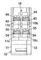
本実施形態のリモコンリレーについて図1乃至図9を参照して説明する。図1はリモコンリレーの分解斜視図を示しており、リモコンリレーのケース10は、分電盤協約寸法として規格化されている1個モジュール寸法(単位寸法)に設定されており、側面が開口した箱状のボディ11と、ボディ11の開口面を覆うカバー12とからなる。ボディ11とカバー12とは、ボディ11およびカバー12に形成した組立孔13,14にかしめピン15を挿通し、ボディ11におけるカバー12とは反対側の側面に突出するかしめピン15の先端部をかしめることによって一体に結合される。また、ケース10にはマイクロスイッチからなる補助接点を収納するための補助スペース16が形成され、この補助スペース16に補助接点を収納しないときには補助スペース16の開口を閉塞するように閉塞板17が装着される。
【0017】
ケース10の中には有極電磁石20が収納される。有極電磁石20は、図1、図2及び図8に示すように、略コ字形に形成された2個のヨーク21を備え、2個のヨーク21は両脚片の先端面間にギャップ22を介して対向するように配置される。各ヨーク21の中央片には永久磁石23の一方の磁極が当接し、永久磁石23の他方の磁極には補助ヨーク24が結合される。補助ヨーク24はコイル25を巻装したコイル枠26を囲むように配設され、コイル枠26の中にはプランジャ27がコイル枠26の軸方向に進退自在に挿通される。またプランジャ27には進退時にヨーク21または補助ヨーク24に当接してプランジャ27の移動範囲を規制し、且つ磁気回路を形成する2枚の接極子28が固着されている。コイル25は1巻線型であって、コイル25への通電方向に応じてプランジャ27が進退し、且つプランジャ27は永久磁石23の磁力で停止位置に保持される。すなわち、停止位置では、永久磁石23−補助ヨーク24−接極子28−プランジャ27−接極子28−ヨーク21−永久磁石23という経路の閉磁路が形成され、プランジャ27がその位置に保持されるのである。接極子28においてヨーク21との接触面には、薄板状の非磁性体よりなるレシジュアルプレート28aが固着され、接極子28がヨーク21に吸引された状態から容易に離脱できるようにしてある。有極電磁石20は、ボディ11におけるカバー12との対向面に突設された仕切片11f,11gの間に配設され、板ばねよりなる緩衝ばね19が仕切片11gと有極電磁石20との間に挟装されることによって、有極電磁石20が仕切片11fに押し付けられた形で固定される。したがって、緩衝ばね19によって有極電磁石20が固定されるとともに、プランジャ27の進退に伴う振動が緩衝ばね19によって緩和されることになる。
【0018】
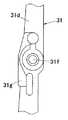
プランジャ27の進退方向の一端部には、絶縁材料である合成樹脂よりなる連動レバー31が、軸ピン32によって回転自在に結合される。プランジャ27の一端部は連動レバー31に形成された凹溝31bに挿入される。凹溝31bの中には軸受突片31cが立設されており、この軸受突片31cに穿設された軸挿通孔31h内に挿通される軸ピン32によってプランジャ27が軸受突片31cに軸着される。また、有極電磁石20のコイル枠26の外周面には一対の支持片26a,26aが突設され、各支持片26aには軸挿通孔26c,26cが形成されており、この軸挿通孔26c,26cと連動レバー31を貫通する貫通孔31fとに1本の軸ピン33を挿通することによって、連動レバー31が軸ピン33を中心として回転自在に軸支される。
【0019】
また、連動レバー31は仕切板31aを有しており、仕切板31aの左右両側面にそれぞれ接触子保持台31dが一体に突設され、接触子保持台31dには上記凹溝31bが形成される。仕切板31aの両側面には、接触子保持台31dとの対向面が開口する略コ字形に形成されたばね受け突部31eも突設される。ばね受け突部31eは、コイルばねよりなる接圧ばね34の一端部を保持する。接圧ばね34の他端は、接触子保持台31dとばね受け突部31eとの間に挿入される可動接触子40に弾接する。すなわち、2個の可動接触子40が1つの連動レバー31に保持されるのである。
【0020】
ところで、軸ピン33は金属製であって、ボディ11とカバー12との間の距離よりも若干長い寸法に形成されており、軸ピン33の一端はボディ11の内面に形成された嵌合凹所11hに、他端はカバー12の内面に形成された嵌合凹所12aにそれぞれ圧入され、ボディ11とカバー12との間に軸ピン33が固定される。ここで、可動接触子40と軸ピン33との間の連動レバー31の部位には、絶縁壁31gが連動レバー31と一体に形成されており、絶縁壁31gによって可動接触子40と軸ピン33との間の絶縁性が向上するので、一対の可動接触子40の間で軸ピン33を通る電路が形成されることはなく、一対の可動接触子40の間の絶縁距離を大きくとることができる。このように、絶縁壁31gを設けることによって軸ピン33と可動接触子40との間の絶縁距離を大きくとっているので、軸ピン33を1本の軸体で構成することができ、従来のリモコンリレーのように軸ピン33を2本に分け、両軸ピン33間を絶縁する場合に比べて、部品数が少なくなり、組立作業性が向上する。また、軸ピン33の両端はそれぞれボディ11及びカバー12内面の嵌合凹所11h,12aに圧入され、ボディ11とカバー12との間で軸ピン33を挟持しているので、従来のリモコンリレーのように軸ピン33を支持片26aの軸挿通孔26c内に固定するために、軸ピン33の端部にローレット加工を施す必要がなく、軸ピン33の製造コストを低減でき、さらに、軸ピン33がケースに位置決めされるので、連動レバー31の取付位置のばらつきが少なくなり、動作特性のばらつきが低減する。
【0021】
ところで、連動レバー31に保持される可動接触子40は短冊状であって、長手方向の一端部に可動接点41が固着され、他端部に編組銅線よりなる接続線42を介して端子板43が接続されている。この端子板43には、座金付きの端子ねじ44が螺合する。また、可動接触子40の長手方向の中間部には接圧ばね34の座となる突部45が形成され、突部45よりも下方には位置決め孔46が穿孔されている。位置決め孔46には連動レバー31に突設された位置決め突起35が挿通される。連動レバー31には位置決め突起35の側方に表面が湾曲して可動接触子40が当接する支点突起36が突設されており、この支点突起36に可動接触子40が当接するようになっている。可動接触子40において可動接点41よりも下方の端部には可動電磁鉄片47が固着される。また、連動レバー31の上端には、ケース10に開口する表示窓10aに臨む表示片38が一体に設けられ、表示片38には「ON」、「OFF」の文字が表記されている。さらに、表示片38において「ON」、「OFF」の文字の間であって、表示窓10aから常時露出している部位には、操作溝38aが形成され、ドライバの先端部などの工具を表示窓10aに挿入して操作溝38aに係合させることによって、連動レバー31をケース10の外部から手操作で操作できるようにしてある。
【0022】
可動接点41に離接する固定接点51は、導電性の板金を折曲して形成されケース10に固定された固定端子板50の一端部に固着され、固定端子板50の他端部はケース10の外部に露出する。固定端子板50は固定接点51を設けた一端部から可動接触子40に沿って下方に向かう接点片52を備え、接点片52の下端部には可動電磁鉄片47に対向するように固定電磁鉄片53が固着されている。また、ケース10の外方に突出する端子板54には座金付きの端子ねじ55が螺合している。ここで、可動接触子40および固定端子板50は2個ずつケース10に収納されているのであって主接点は2極に構成されることになる。
【0023】
ケース10において可動接触子40および固定端子板50を収納している部位には、ケース10の幅方向の略中央部に隔壁18が立設される。ボディ11の下壁における隔壁18に対応する部位にはカバー12側が下がった段部11aが形成され、段部11aに隔壁18の下端部を当接させるとともに、隔壁18の下端の一面側に突設された横片18aをボディ11の下壁に載置することによって隔壁18の位置決めがなされるようにしてある。ここに、ボディ11において隔壁18が載置される部位の下壁はボディ11の長手方向(図2の左右方向)において段を形成しており、隔壁18の横片18aがこの下壁に沿うように屈曲していることによって、ボディ11の長手方向においても隔壁18の位置決めがなされている。また、隔壁18は、かしめピン15が挿通される部位に穿設された貫通孔18eに、ボディ11に突設されたボス11eが挿通されることによっても位置決めされている。
【0024】
ボディ11における隔壁18との対向面には2極のうちの一方の端子板43および端子板54がそれぞれ載置される2つの端子基台11b,11cが突設され、隔壁18におけるカバー12との対向面には2極のうちの他方の端子板43および端子板54がそれぞれ載置される2つの端子基台18b,18cが突設される。端子基台11b,18bと端子基台11c,18cとは、上下2段に配置されており、可動接点41に接続された端子板43と固定接点51に接続された端子板54とは異なる高さ位置に配置されるようにしてある。ボディ11における隔壁18との対向面には仕切片11dが突設され、隔壁18において仕切片11dに対応する部位にもカバー12に向かって仕切片18dが突設されている。さらに、ボディ11におけるカバー12との対向面には隔壁18の一部が当接する仕切片11fが突設されている。端子板43は、端子基台11b,18bと仕切片11d,18dの下面とによって固定され、端子板54は端子基台11b,18bと端子基台11c,18cとによって固定されることになる。また、仕切片11fは、可動接点41と固定接点51との開極時に発生するアークによる有極電磁石20への悪影響を軽減する。
【0025】
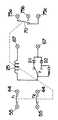
ところで、このリモコンリレーではコイル25が1巻線型であるので、プランジャ27を進退させるには、コイル25への通電方向を反転させることが必要である。図9はリモコンリレーの内部回路図を示しており、コイル25には2種類の給電経路を択一的に選択する切換接点rが接続されており、切換接点rにより選択された各給電経路にはそれぞれ逆流阻止要素としてのダイオードD1,D2が接続されている。ダイオードD1,D2における切換接点rとは反対側の端子は共通に接続される。ダイオードD1,D2は各給電経路を通過する電流が互いに逆向きになる関係に接続されているのであって、一方の給電経路で切換接点r→コイル25という向きの電流を通過させるとすれば、他方の給電経路ではコイル25→切換接点rという向きの電流を通過させるようになっている。また、一方のダイオードD2のアノードと切換接点rの共通接点との間にはコンデンサ及び抵抗の直列回路であるリセット用の微分回路が接続される。この回路構成によって、有極電磁石20のコイル25への通電方向の切換により、可動接点41と固定接点51とからなる主接点r1,r2を開閉することができるのである。
【0026】
このようにコイル25への通電方向が切換接点rにより選択されるから、コイル25への通電時にプランジャ27の進退の位置を逆転させるような通電方向が選択されるように、切換接点rをプランジャ27の進退に応じて切り換える必要がある。すなわち、プランジャ27の進退と切換接点rとを連動させる必要がある。そこで、本実施形態では、連動レバー31に接点操作片37を突設し、この接点操作片37によって切換接点rの切換操作を行うようにしてある。
【0027】
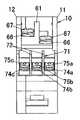
切換接点rは、有極電磁石20の上面に載置される接点基板61を備え、接点基板61には2枚の固定接点板62a,62bと、各固定接点板62a,62bにそれぞれ対向する可動接点板63a,63bとが固定される。接点基板61は周部の要所に切欠61aを有し、有極電磁石20のコイル枠26の外周面から上方に突設された固定爪26bが切欠61aに係合することによって、有極電磁石20に対する位置決めがなされている。両可動接点板63a,63bは一端部が略コ字形の接点支持板64の各脚片に固着されていて互いに電気的に接続され、各可動接点板63a,63bは対応する固定接点板62a,62bに対して接触する向きのばね力を有している。連動レバー31の接点操作片37は両可動接点板63a,63bの間に挿入されているのであって、連動レバー31がプランジャ27の進退に伴って揺動すると、連動レバー31の両端末位置ではいずれか一方の可動接点板63a,63bが固定接点板62a,62bに接触し、他方の可動接点板63a,63bが固定接点板62a,62bから離れるようになっている。
【0028】
固定接点板62a,62bおよび可動接点板63a,63bは、接点基板61に取着したプリント配線基板よりなる回路基板65に電気的に接続される。回路基板65には上述したダイオードやリセット用の微分回路の回路部品が実装される。さらに、接点基板61には一対のコイル端子板66が固定され、各コイル端子板66には座金付の端子ねじ67が螺合する。したがって、コイル端子板66を通して入力される外部信号を受けてコイル25に通電すると、通電方向に応じてプランジャ27が進退するのである。ここに、両コイル端子板66は上下にずれた位置に配設されている。また、接点基板61の上面には、固定接点板62a,62bおよび可動接点板63a,63bと回路基板65とを仕切り、またコイル端子板66と他の部材との間を仕切るように仕切片61bが突設される。
【0029】
次に動作を説明する。まず、プランジャ27が突出する向きにコイル25に通電したとすると、プランジャ27の突出に伴って、連動レバー31は軸ピン33を中心として図2中右回りに回転し、可動接点41が固定接点51に接触する。ここで、可動接触子40は支点突起36に当接しており、接圧ばね34によって支点突起36を中心として右回りに付勢されているから、可動接点41の固定接点51に対する接触圧が接圧ばね34によって得られることになる。この時、図2に示すように、可動接点板63bは固定接点板62bから離れ、可動接点板63aが固定接点板62aに接触し、コイル25への通電方向としてプランジャ27を引退させる向きの電流のみが許可された状態になる。尚、可動接点41が固定接点51に接触した状態では、コイル25への通電を停止しても永久磁石23の磁力によってその状態が保持される。
【0030】
次に、コイル25への通電方向を反転させると、プランジャ27が引退し、連動レバー31が軸ピン33を中心として図2中左回りに回転するから、可動接点41が固定接点51から離れて主接点が開極することになる。主接点の開極時にはアークが発生するが、両可動接点41の間に隔壁18が存在していることによって隣接する主接点間の絶縁距離が大きくなり、しかも、隣接する可動接触子40の間には連動レバー31の仕切板31aが存在していることによって、可動接触子40の間についても絶縁距離が大きくなっている。ここにおいて、主接点の閉極時において短絡電流のようなきわめて過大な電流が主接点を通過したときに、主接点がわずかでも開極するとアークが生じて主接点の周辺部が溶融したり、急激な熱膨張によってケース10が破裂する可能性があるので、短絡電流のような過大電流の通過時には可動電磁鉄片47と固定電磁鉄片53との間に電磁力による吸引力を作用させて、可動接点41が固定接点51から離れることがないように保持するのである。
【0031】
ところで、上述したようにケース10の補助スペース16には補助接点となる小型スイッチ70が収納される。小型スイッチ70は、絶縁材料である合成樹脂よりなる取付フレーム71に装着された形でケース10に収納される。この取付フレーム71は略平行な2枚の仕切板72を連結板73の一面に一体に結合した形状に形成され、両仕切板72によって3個の端子板74a,74b,74cを互いに分離するようになっている。各端子板74a,74b,74cには座金付きの端子ねじ75a,75b,75cが螺合し、各端子板74a,74b,74cには小型スイッチ70の端子70aがそれぞれ電気的に接続される。ここに、小型スイッチ70は共通接点と常開接点と常閉接点とを備えたc接点を有し、小型スイッチ70の一面には操作子70bが設けられている。この操作子70bを押操作すれば共通接点と常開接点とが短絡され、押操作を停止すれば共通接点と常閉接点とが短絡されるようになっている。操作子70bは、有極電磁石20のプランジャ27において連動レバー31との結合部位とは反対側の端部に対向して配置され、プランジャ27の進退に伴って操作子70bが操作されるようになっている。すなわち、可動接点41と固定接点51とからなる主接点が閉極した状態では操作子70bは押操作されないから、共通接点と常閉接点とが短絡し、主接点が開極すると操作子70bが押操作されて、共通接点と常開接点とが短絡するのである。
【0032】
(実施形態2)
本実施形態のリモコンリレーについて図10乃至図12を参照して説明する。実施形態1のリモコンリレーでは、軸ピン33を金属で形成するとともに、可動接触子40と軸ピン33との間の連動レバー31の部位に絶縁壁31gを設けているが、本実施形態のリモコンリレーでは、軸ピン33を絶縁性を有する合成樹脂で形成している。また、軸ピン33は絶縁性を有する材料から形成されているので、実施形態1のリモコンリレーのように、可動接触子40と軸ピン33との間を絶縁する絶縁壁31gを設ける必要はない。尚、軸ピン33及び連動レバー31以外の構成は実施形態1のリモコンリレーと同様であるので、同一の構成要素には同一の符号を付して、その説明を省略する。
【0033】
本実施形態では、軸ピン33を絶縁性を有する合成樹脂から形成しており、軸ピン33はボディ11とカバー12との間の距離よりも若干長い寸法に形成されている。有極電磁石20のコイル枠26の外周面には一対の支持片26a,26aが突設され、各支持片26aには軸挿通孔26cがそれぞれ形成されており、軸挿通孔26c,26cを通して、連動レバー31を貫通する貫通孔31fに軸ピン33を挿通することによって、連動レバー31は軸ピン33を中心として回転自在に軸支される。この時、軸ピン33の両端部は各支持片26aの端面から突出しており、連動レバー31が取り付けられた有極電磁石20をケース10内部に収納すると、軸ピン33の一端はボディ11内面の嵌合凹所11hに、他端はカバー12内面の嵌合凹所12aにそれぞれ圧入されており、ボディ11とカバー12との間に軸ピン33が挟持される。
【0034】
ここで、軸ピン33は絶縁性を有する合成樹脂から形成されているので、可動接触子40と軸ピン33との間の絶縁性が向上し、一対の可動接触子40の間で軸ピン33を通る電路が形成されることはなく、一対の可動接触子40の間の絶縁距離を大きくとることができる。このように、軸ピン33を絶縁性を有する合成樹脂から形成することによって、両可動接触子40間の絶縁距離を確保しているので、軸ピン33を1本の軸体で構成することができ、従来のリモコンリレーのように軸ピン33を2本に分け、両軸ピン33間を絶縁する場合に比べて、部品数が少なくなり、組立作業性が向上する。また、軸ピン33の両端はそれぞれボディ11及びカバー12内面の嵌合凹所11h,12aに圧入され、ボディ11とカバー12との間で軸ピン33を挟持しているので、従来のリモコンリレーのように軸ピン33を支持片26aの軸挿通孔26c内に固定するために、軸ピン33の端部にローレット加工を施す必要がなく、軸ピン33の製造コストを低減でき、且つ、軸ピン33がケースに位置決めされるので、連動レバー31の取付位置のばらつきが少なくなり、動作特性のばらつきが低減する。
【0035】
(実施形態3)
本実施形態のリモコンリレーについて図13乃至図17を参照して説明する。上述した実施形態1又は2のリモコンリレーでは、可動接点41に電気的に接続された端子板43と、固定接点51に電気的に接続された端子板54とは、ケース10の長手方向における一端部に、ケース10の長手方向において同一直線上に並べて配置されると共に、ケースの高さ方向において高さをずらして配置されており、端子板43と端子板54とは略平行に配置されているが、本実施形態では、実施形態2のリモコンリレーにおいて、下側の端子板(第2の端子板)54を、上側の端子板(第1の端子板)43に対して、上側の端子板43に電線が接続された状態でも斜め上方から端子ねじ55に工具を挿入できるように傾斜させた状態で配置している。すなわち、端子ねじ端子板54は端子板43に対して斜め前方に傾斜している。また、本実施形態ではケース10内に補助接点となる小型スイッチ70を収納しておらず、補助スペース16の開口を閉塞板17で閉塞してある。尚、端子板54の配置以外は実施形態2のリモコンリレーと同様であるので、同一の構成要素には同一の符号を付して、その説明を省略する。
【0036】
上側の端子板43はケース10上面に対して略平行に配置されているので、端子ねじ(第1の端子ねじ)44により端子板43に接続された電線はケース10上面に対して略平行な方向に引き出される。一方、下側の端子板54は上側の端子板43に対して傾斜させた状態でケース10に取り付けられており、端子ねじ(第2の端子ねじ)55により端子板54にねじ止めされた電線は斜め下向きに引き出されるようになっている。上述のように下側の端子板54は上側の端子板43に対して傾斜しているので、上側の端子板43に電線が接続されている状態でも、下側の端子板54に螺合する端子ねじ55に斜め上方からプラスドライバーなどの工具60を差し込むことができ、ねじ締めの確認を容易に行うことができる。尚、本実施形態では、実施形態2のリモコンリレーにおいて、下側の端子板54を上側の端子板43に対して傾斜させた状態で配置しているが、実施形態1のリモコンリレーにおいて、下側の端子板54を上側の端子板43に対して、上側の端子板43に電線が接続された状態でも端子ねじ55に工具を挿入できるように傾斜させた状態で配置しても良く、同様の効果が得られる。
【0037】
ところで、この種のリモコンリレーとしては、図18及び図19に示すように、図示しない電磁石装置を収納する角筒状のケース80に、筒状をした補助接点収納部81を付設し、補助接点収納部81に一方の開口部から補助接点ブロック82を嵌め込んで構成されるものもある。補助接点ブロック82は、図19(a)(b)に示すように、合成樹脂製のベース83と、導電性の金属板からなる可動端子板84,85と、導電性の金属板からなる固定端子板86と、ばね弾性を有する導電性金属板からなる可動接点ばね87などから構成されている。ベース83には補助接点収納部81への挿入方向に沿って走る嵌め込み溝88a〜88cが形成されている。中央の嵌め込み溝88bには固定端子板86が嵌め込まれており、固定端子板86の両端部はベース83に支持されている。両側の嵌め込み溝88a,88cには可動端子板84,85の後部がそれぞれ嵌め込まれ、可動端子板84,85は固定端子板86に対して略平行に配置されている。また、固定端子板86と対向する可動端子板85の面には可動接点ばね87がかしめ固定されている。固定端子板86両面には固定接点86aが固着されており、ベース83に形成された切欠部83aを介して、可動端子板84及び可動接点ばね87に設けた可動接点(図示せず)と対向している。
【0038】
ここで、可動端子板84,85及び可動接点ばね87の自由端はベース83の先端面から突出しており、補助接点ブロック82を補助接点収納部81内に嵌め込んだ際に、可動端子板84及び可動接点ばね87の自由端は、電磁石装置への通電或いは手動操作に応じて揺動するレバー(図示せず)に弾接する。そして、電磁石装置への通電或いは手動操作に応じてレバーが揺動すると、レバーによって可動端子板84及び可動接点ばね87が押動され、可動端子板84又は可動接点ばね87に設けられた可動接点が固定接点86aと接触又は開離するのである。
【0039】
ところで、補助接点ブロック82は、補助接点収納部81にベース83を圧入することによってケース80に固定されているだけなので、振動や衝撃によってベース83が抜け、補助接点の動作特性が変化するという問題がある。そこで、図20に示すように、補助接点収納部81の表面に嵌合孔81aを形成するとともに、嵌合孔81aと嵌合する嵌合突起83bをベース83に形成しており、補助接点収納部81内にベース83を圧入すると、補助接点収納部81の嵌合孔81aとベース83の嵌合突起83bとが凹凸嵌合し、ベース83の抜け止めが行われるので、補助接点の動作特性が安定する。
【0040】
また、図19(a)(b)に示す補助接点ブロック82では、嵌め込み溝88a,88cにおける可動端子板84,85及び可動接点ばね87の自由端側の開放端において、可動端子板84,85及び可動接点ばね87が押し撓められる側の角部83c,83dが略直角に形成されているので、可動端子板84,85及び可動接点ばね87がレバーによって押し撓められると、その角部83c,83dに荷重が集中し、発生する熱によって角部83c,83dが変形して、補助接点の動作特性が変化するという問題があった。
【0041】
そこで、図21(a)(b)に示すように、嵌め込み溝88a,88cにおける可動端子板84,85及び可動接点ばね87の自由端側の開放端において、可動端子板84及び可動接点ばね87がレバーによって押し撓められる側の角部83c,83dの断面形状を曲面形状に形成することによって、可動端子板84,85及び可動接点ばね87がレバーによって押し撓められた場合でも、可動端子板84,85及び可動接点ばね87の荷重が一点に集中して加わることがなく、角部83c,83dが変形して補助接点の動作特性が変化するのを防止できる。
【0042】
【発明の効果】
上述のように、請求項1の発明は、1巻線型のコイルがコイル枠に巻装されコイルへの通電方向に応じてプランジャが進退する有極電磁石と、コイル枠に突設された一対の支持片と、一対の支持片にそれぞれ設けた軸挿通孔に挿通される軸ピンを中心として回転自在に軸支され軸ピンとは異なる位置でプランジャに結合されていてプランジャの進退に応じて軸ピンの回りに回転する絶縁材料よりなる連動レバーと、連動レバーに保持され一端部に可動接点を備える複数個の可動接触子と、各可動接点に離接する複数個の固定接点とをケース内に備え、軸ピンを、各支持片の軸挿通孔に両側部がそれぞれ挿通される1本の軸体で構成し、可動接触子と軸ピンとの間の絶縁距離を確保するための絶縁手段を設けたことを特徴とし、連動レバーには複数個の可動接触子が保持されており、プランジャの進退に応じて連動レバーが軸ピンの回りを回転することにより、可動接点と固定接点とが離接するので、複数個の可動接触子を1個の有極電磁石で駆動することができ、且つ、連動レバーを軸支する軸ピンは1本の軸体で構成されているので、複数個の可動接触子の間の絶縁距離を向上させるために軸ピンを複数本の軸体で構成した場合に比べて、部品数を少なくでき、組立作業性を向上させることができ、さらに、可動接触子と軸ピンとの間の絶縁距離を確保する絶縁手段を設けているので、可動接触子と軸ピンとの間の絶縁距離を大きくとることができ、複数個の可動接触子の間で軸ピンを通る電路が形成されないから、複数個の可動接触子の間の絶縁性が向上するという効果がある。
【0043】
請求項2の発明は、請求項1の発明において、上記軸ピンは金属で形成され、上記絶縁手段は、可動接触子と軸ピンとの間の連動レバーの部位に設けた絶縁壁からなることを特徴とし、軸ピンは金属で形成されているので、軸ピンの強度を高めることができ、且つ、絶縁壁が可動接触子と軸ピンとの間の連動レバーの部位に設けられているので、可動接触子と軸ピンとの間の絶縁距離を大きくとることができ、複数個の可動接触子の間で軸ピンを通る電路が形成されないから、複数個の可動接触子の間の絶縁性が向上するという効果がある。
【0044】
請求項3の発明は、請求項2の発明において、上記絶縁壁は連動レバーと一体に形成されたことを特徴とし、絶縁壁は連動レバーと一体に形成されているので、部品数が少なくなり、組立作業性が向上するという効果がある。
【0045】
請求項4の発明は、請求項1の発明において、上記絶縁手段は、絶縁性を有する材料で形成した軸ピンからなることを特徴とし、軸ピンは絶縁性を有する材料で形成されているので、複数個の可動接触子の間で軸ピンを通る電路が形成されることはなく、複数個の可動接触子の間の絶縁距離を大きくとれるという効果がある。
【0046】
請求項5の発明は、請求項1乃至4の発明において、軸ピンの両端が嵌合固定される嵌合凹部をケース内面に設けたことを特徴とし、軸ピンの両端はケース内面の嵌合凹部に嵌合固定されるので、ケースに軸ピンを位置決めすることができ、ケース内における軸ピンの位置のばらつきが低減し、リモコンリレーの動作特性が安定するという効果がある。
【0047】
請求項6の発明は、請求項1乃至5の発明において、複数個の可動接触子の間を仕切る仕切板を連動レバーに設けたことを特徴とし、仕切板によって複数個の可動接触子の間が電気的に絶縁されるので、複数個の可動接触子の間の絶縁距離を大きくとれるという効果がある。
【0048】
請求項7の発明は、請求項1乃至6の発明において、可動接点に電気的に接続され第1の端子ねじが螺合する第1の端子板と、固定接点に電気的に接続され第2の端子ねじが螺合する第2の端子板とを、ケースの高さ方向において位置をずらした状態で、両端子板にねじ止めされる電線が引き出される方向に並べて配置し、ケースの高さ方向において下側に対置された端子板を、上側に配置された端子板に電線が接続された状態でも斜め上方から端子ねじに工具を挿入できるように、上側に配置された端子板に対して傾斜させたことを特徴とし、第1及び第2の端子板はケースの高さ方向において位置をずらした状態で配置されているので、第1及び第2の端子板を同一平面内に並設する場合に比べて、第1及び第2の端子板の設置スペースを小さくでき、且つ、第1及び第2の端子板の内、下側の端子板を、上側の端子板に電線が接続された状態でも斜め上方から端子ねじに工具を挿入できるように、上側の端子板に対して傾斜させているので、斜め上方から下側の端子板に螺合された端子ねじにドライバなどの工具を差し込むことができ、ねじ締めの確認を容易に行えるという効果がある。
【図面の簡単な説明】
【図1】実施形態1のリモコンリレーの分解斜視図である。
【図2】同上のカバーを外した状態の一部破断せる側面図である。
【図3】同上の上面図である。
【図4】同上の左側から見た側面図である。
【図5】同上の右側から見た側面図である。
【図6】同上に用いる連動レバーを示し、(a)は正面図、(b)は側面図である。
【図7】同上に用いる連動レバーの要部拡大図である。
【図8】同上に用いる電磁石ブロックの外観斜視図である。
【図9】同上の内部回路図である。
【図10】実施形態2のリモコンリレーの分解斜視図である。
【図11】同上のカバーを外した状態の一部破断せる側面図である。
【図12】同上に用いる電磁石ブロックの外観斜視図である。
【図13】実施形態3のリモコンリレーのカバーを外した状態の一部破断せる側面図である。
【図14】同上の上面図である。
【図15】同上の左側から見た側面図である。
【図16】同上の右側から見た側面図である。
【図17】同上の使用状態を説明する説明図である。
【図18】別のリレーの一部省略せる分解斜視図である。
【図19】同上に用いる補助接点ブロックを示し、(a)は外観斜視図、(b)はベースの上面図である。
【図20】また別のリレーの一部省略せる分解斜視図である。
【図21】同上に用いる補助接点ブロックを示し、(a)は外観斜視図、(b)はベースの上面図である。
【図22】従来のリモコンリレーの分解斜視図である。
【図23】同上のカバーを外した状態の一部破断せる側面図である。
【図24】同上の電磁石ブロックの外観斜視図である。
【図25】同上の使用状態を説明する説明図である。
【符号の説明】
10 ケース
20 電磁石装置
25 コイル
26 コイル枠
26a 支持片
26c 軸挿通孔
27 プランジャ
31 連動レバー
31g 絶縁壁
33 軸ピン
40 可動接触子
41 可動接点
51 固定接点[0001]
BACKGROUND OF THE INVENTION
The present invention relates to a remote control relay.
[0002]
[Prior art]
Conventionally, as shown in FIG. 22 to FIG. 24, a
[0003]
In this type of remote control relay having a main contact of multiple poles, a
[0004]
Here, each
[0005]
[Problems to be solved by the invention]
In the remote control relay configured as described above, the
[0006]
Further, the
[0007]
The present invention has been made in view of the above problems, and an object of the present invention is to provide a remote control relay having a reduced number of parts and an improved insulation performance. Further, an object of the invention of claim 5 is to provide a remote control relay having stable operating characteristics in addition to the above object, and an object of the invention of claim 7 is to connect the electric wires in addition to the above object. It is an object of the present invention to provide a remote control relay capable of easily confirming the above.
[0008]
[Means for Solving the Problems]
In order to achieve the above object, the first aspect of the present invention provides a one-winding type coil.Is wound around the coil frame A polarized electromagnet in which the plunger advances and retreats according to the energization direction of the coil;A pair of support pieces projecting from the coil frame and shaft insertion holes provided in the pair of support pieces are inserted. An interlocking lever made of an insulating material that is pivotally supported around the shaft pin and is coupled to the plunger at a position different from the shaft pin and rotates around the shaft pin as the plunger moves forward and backward, and one end held by the interlocking lever The case is provided with a plurality of movable contacts each having a movable contact at a portion thereof, and a plurality of fixed contacts that are separated from and contacting each movable contact.The both side portions are respectively inserted into the shaft insertion holes of the support pieces. It is composed of a single shaft body and is provided with an insulating means for ensuring an insulation distance between the movable contact and the shaft pin. The interlocking lever holds a plurality of movable contacts. As the interlocking lever rotates around the shaft pin according to the advancement and retraction of the plunger, the movable contact and the fixed contact are separated from each other, so that a plurality of movable contacts can be driven by one polarized electromagnet. In addition, since the insulating means for ensuring the insulation distance between the movable contact and the shaft pin is provided, it is possible to increase the insulation distance between the movable contact and the shaft pin. Since an electric path passing through the shaft pin is not formed between the plurality of movable contacts, the insulation between the plurality of movable contacts can be improved, and further, an insulation distance between the movable contact and the shaft pin is secured by the insulating means. So, make up the shaft pin with one shaft body Can, as compared with the case where the axial pin in order to ensure an insulation distance between the movable contact child shaft a plurality of the number of parts is reduced, thereby improving the assembling workability.
[0009]
According to a second aspect of the present invention, in the first aspect of the invention, the shaft pin is made of metal, and the insulating means includes an insulating wall provided at a position of the interlocking lever between the movable contact and the shaft pin. Since the insulating wall is provided at the position of the interlocking lever between the movable contact and the shaft pin, the insulation distance between the movable contact and the shaft pin can be increased, and a plurality of movable contacts Since an electric path that passes through the shaft pin is not formed between the plurality of movable contacts, the insulation between the plurality of movable contacts is improved, and the insulation distance between the movable contact and the shaft pin is secured by the insulating wall. Therefore, the shaft pin can be formed of metal, and the strength of the shaft pin can be increased.
[0010]
The invention of claim 3 is characterized in that, in the invention of claim 2, the insulating wall is formed integrally with the interlocking lever, and the insulating wall is formed integrally with the interlocking lever, so that the number of parts is reduced. As a result, assembly workability is improved.
[0011]
According to a fourth aspect of the present invention, in the first aspect of the invention, the insulating means comprises a shaft pin made of an insulating material, and the shaft pin is made of an insulating material. An electric circuit passing through the shaft pin is not formed between the plurality of movable contacts, and the insulation distance between the plurality of movable contacts can be increased, and the shaft is made of an insulating material. Since the pins are formed, the shaft pins can be formed by a single shaft body, the number of parts can be reduced, and the assembly workability can be improved.
[0012]
According to a fifth aspect of the present invention, in the first to fourth aspects of the invention, a fitting recess in which both ends of the shaft pin are fitted and fixed is provided on the inner surface of the case, and both ends of the shaft pin are fitted to the inner surface of the case. Since it is fitted and fixed in the recess, the shaft pin can be positioned in the case, the variation in the position of the shaft pin in the case can be reduced, and the operation characteristics of the remote control relay can be stabilized.
[0013]
According to a sixth aspect of the present invention, in the first to fifth aspects of the present invention, a partition plate for partitioning the plurality of movable contacts is provided on the interlocking lever, and the partition plate is provided between the plurality of movable contacts. Is electrically insulated, it is possible to increase the insulation distance between the plurality of movable contacts.
[0014]
According to a seventh aspect of the present invention, in the first to sixth aspects of the invention, a first terminal plate electrically connected to the movable contact and screwed into the first terminal screw, and a second terminal electrically connected to the fixed contact. The second terminal plate with which the terminal screws are screwed together is arranged side by side in the direction in which the wires screwed to both terminal plates are pulled out, with the position being shifted in the height direction of the case. The terminal plate placed on the lower side in the direction with respect to the terminal plate placed on the upper side so that the tool can be inserted into the terminal screw from obliquely above even when the electric wire is connected to the terminal plate placed on the upper side. Since the first and second terminal plates are arranged in a state of being shifted in the height direction of the case, the first and second terminal plates are arranged side by side in the same plane. Compared to the case where the first and second terminal boards are installed, Of the first and second terminal plates, the lower terminal plate so that the tool can be inserted into the terminal screw obliquely from above even when the electric wire is connected to the upper terminal plate. Since it is inclined with respect to the terminal plate, a tool such as a screwdriver can be inserted into the terminal screw screwed into the lower terminal plate from diagonally above, and the screw tightening can be easily confirmed.
[0015]
DETAILED DESCRIPTION OF THE INVENTION
Embodiments of the present invention will be described with reference to the drawings.
[0016]
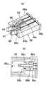
(Embodiment 1)
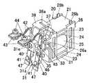
The remote control relay of this embodiment will be described with reference to FIGS. FIG. 1 is an exploded perspective view of a remote control relay. The remote
[0017]
A
[0018]
An interlocking
[0019]
Further, the interlocking
[0020]
By the way, the
[0021]
By the way, the
[0022]
The fixed
[0023]
In the
[0024]
Two
[0025]
By the way, in this remote control relay, since the
[0026]
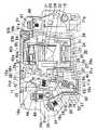
Thus, since the energizing direction to the
[0027]
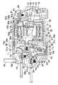
The switching contact r includes a
[0028]
The fixed
[0029]
Next, the operation will be described. First, assuming that the
[0030]
Next, when the energizing direction of the
[0031]
By the way, as described above, the
[0032]
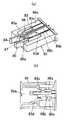
(Embodiment 2)
The remote control relay of this embodiment will be described with reference to FIGS. In the remote control relay according to the first embodiment, the
[0033]
In the present embodiment, the
[0034]
Here, since the
[0035]
(Embodiment 3)
The remote control relay of this embodiment will be described with reference to FIGS. In the remote control relay of Embodiment 1 or 2 described above, the
[0036]
Since the
[0037]
By the way, as this kind of remote control relay, as shown in FIGS. 18 and 19, a cylindrical auxiliary
[0038]
Here, the free ends of the
[0039]
By the way, since the
[0040]
Further, in the
[0041]
Therefore, as shown in FIGS. 21A and 21B, the
[0042]
【The invention's effect】
As described above, the invention of claim 1 is a one-winding type coil.Is wound around the coil frame A polarized electromagnet in which the plunger advances and retreats according to the energization direction of the coil;A pair of support pieces projecting from the coil frame and shaft insertion holes provided in the pair of support pieces are inserted. An interlocking lever made of an insulating material that is pivotally supported around the shaft pin and is coupled to the plunger at a position different from the shaft pin and rotates around the shaft pin as the plunger moves forward and backward, and one end held by the interlocking lever The case is provided with a plurality of movable contacts each having a movable contact at a portion thereof, and a plurality of fixed contacts that are separated from and contacting each movable contact.The both side portions are respectively inserted into the shaft insertion holes of the support pieces. It is composed of a single shaft body and is provided with an insulating means for ensuring an insulation distance between the movable contact and the shaft pin. The interlocking lever holds a plurality of movable contacts. As the interlocking lever rotates around the shaft pin according to the advancement and retraction of the plunger, the movable contact and the fixed contact are separated from each other, so that a plurality of movable contacts can be driven by one polarized electromagnet. Also, since the shaft pin that pivotally supports the interlocking lever is composed of one shaft body, the shaft pin is composed of a plurality of shaft bodies in order to improve the insulation distance between the plurality of movable contacts. Compared to the case, the number of parts can be reduced, the assembling workability can be improved, and the insulating means for ensuring the insulation distance between the movable contact and the shaft pin is provided. The insulation distance between the shaft pins can be increased, Since path through the shaft pin between the several movable contact is not formed, the effect of improving the insulation between the plurality of movable contact.
[0043]
According to a second aspect of the present invention, in the first aspect of the invention, the shaft pin is made of metal, and the insulating means includes an insulating wall provided at a position of the interlocking lever between the movable contact and the shaft pin. As a feature, the shaft pin is made of metal, so the strength of the shaft pin can be increased, and the insulating wall is provided at the position of the interlocking lever between the movable contact and the shaft pin, so it is movable The insulation distance between the contact and the shaft pin can be increased, and since the electric path passing through the shaft pin is not formed between the plurality of movable contacts, the insulation between the plurality of movable contacts is improved. There is an effect.
[0044]
The invention of claim 3 is characterized in that, in the invention of claim 2, the insulating wall is formed integrally with the interlocking lever, and the insulating wall is formed integrally with the interlocking lever, so that the number of parts is reduced. There is an effect that the assembly workability is improved.
[0045]
According to a fourth aspect of the present invention, in the first aspect of the present invention, the insulating means includes a shaft pin formed of an insulating material, and the shaft pin is formed of an insulating material. An electric circuit passing through the shaft pin is not formed between the plurality of movable contacts, and the insulation distance between the plurality of movable contacts can be increased.
[0046]
According to a fifth aspect of the present invention, in the first to fourth aspects of the present invention, a fitting recess in which both ends of the shaft pin are fitted and fixed is provided on the inner surface of the case, and both ends of the shaft pin are fitted to the inner surface of the case. Since it is fitted and fixed in the recess, the shaft pin can be positioned in the case, and variations in the position of the shaft pin in the case are reduced, and the operation characteristics of the remote control relay are stabilized.
[0047]
According to a sixth aspect of the present invention, in the first to fifth aspects of the present invention, a partition plate for partitioning a plurality of movable contacts is provided in the interlocking lever, and the partition plate is provided between the plurality of movable contacts. Is electrically insulated, so that the insulation distance between the plurality of movable contacts can be increased.
[0048]
According to a seventh aspect of the present invention, in the first to sixth aspects of the invention, a first terminal plate electrically connected to the movable contact and screwed into the first terminal screw, and a second terminal electrically connected to the fixed contact. The second terminal plate with which the terminal screws are screwed together is arranged side by side in the direction in which the wires screwed to both terminal plates are pulled out, with the position being shifted in the height direction of the case. The terminal plate placed on the lower side in the direction with respect to the terminal plate placed on the upper side so that the tool can be inserted into the terminal screw from obliquely above even when the electric wire is connected to the terminal plate placed on the upper side. Since the first and second terminal plates are arranged in a state of being shifted in the height direction of the case, the first and second terminal plates are arranged side by side in the same plane. Installation space for the first and second terminal boards compared to The lower terminal plate of the first and second terminal plates can be made smaller and the upper terminal plate can be inserted into the terminal screw from an obliquely upper position even when the electric wire is connected to the upper terminal plate. Since it is inclined with respect to the terminal plate, a tool such as a screwdriver can be inserted into the terminal screw screwed into the lower terminal plate from obliquely above, and the screw tightening can be easily confirmed.
[Brief description of the drawings]
FIG. 1 is an exploded perspective view of a remote control relay according to a first embodiment.
FIG. 2 is a side view in which a part of the cover is removed and is partially broken.
FIG. 3 is a top view of the same.
FIG. 4 is a side view seen from the left side of the above.
FIG. 5 is a side view seen from the right side of the above.
6A and 6B show interlocking levers used in the above, wherein FIG. 6A is a front view and FIG. 6B is a side view.
FIG. 7 is an enlarged view of a main part of the interlocking lever used in the above.
FIG. 8 is an external perspective view of an electromagnet block used in the above.
FIG. 9 is an internal circuit diagram of the above.
FIG. 10 is an exploded perspective view of a remote control relay according to a second embodiment.
FIG. 11 is a side view of a partially broken state with the cover removed.
FIG. 12 is an external perspective view of an electromagnet block used in the above.
FIG. 13 is a partially cutaway side view of the third embodiment with the remote control relay cover removed.
FIG. 14 is a top view of the same.
FIG. 15 is a side view seen from the left side of the above.
FIG. 16 is a side view seen from the right side of the above.
FIG. 17 is an explanatory diagram for explaining a use state of the above.
FIG. 18 is an exploded perspective view in which a part of another relay can be omitted.
FIG. 19 shows an auxiliary contact block used in the above, (a) is an external perspective view, and (b) is a top view of the base.
FIG. 20 is an exploded perspective view in which a part of another relay can be omitted.
FIG. 21 shows an auxiliary contact block used in the above, (a) is an external perspective view, and (b) is a top view of a base.
FIG. 22 is an exploded perspective view of a conventional remote control relay.
FIG. 23 is a side view of a partially broken state with the cover removed.
FIG. 24 is an external perspective view of the electromagnet block same as above.
FIG. 25 is an explanatory diagram for explaining the use state of the above.
[Explanation of symbols]
10 cases
20 Electromagnet device
25 coils
26 Coil frame
26a support piece
26c Shaft insertion hole
27 Plunger
31 Interlocking lever
31g insulation wall
33 shaft pin
40 Movable contact
41 Movable contact
51 Fixed contact
Claims (7)
Translated fromJapanesePriority Applications (1)
| Application Number | Priority Date | Filing Date | Title |
|---|---|---|---|
| JP33505999AJP3941306B2 (en) | 1999-11-25 | 1999-11-25 | Remote control relay |
Applications Claiming Priority (1)
| Application Number | Priority Date | Filing Date | Title |
|---|---|---|---|
| JP33505999AJP3941306B2 (en) | 1999-11-25 | 1999-11-25 | Remote control relay |
Publications (2)
| Publication Number | Publication Date |
|---|---|
| JP2001155614A JP2001155614A (en) | 2001-06-08 |
| JP3941306B2true JP3941306B2 (en) | 2007-07-04 |
Family
ID=18284305
Family Applications (1)
| Application Number | Title | Priority Date | Filing Date |
|---|---|---|---|
| JP33505999AExpired - LifetimeJP3941306B2 (en) | 1999-11-25 | 1999-11-25 | Remote control relay |
Country Status (1)
| Country | Link |
|---|---|
| JP (1) | JP3941306B2 (en) |
Families Citing this family (2)
| Publication number | Priority date | Publication date | Assignee | Title |
|---|---|---|---|---|
| JP5276999B2 (en)* | 2009-01-19 | 2013-08-28 | 矢崎総業株式会社 | Case fixing structure |
| JP6312021B2 (en)* | 2014-01-30 | 2018-04-18 | パナソニックIpマネジメント株式会社 | Remote control relay |
- 1999
- 1999-11-25JPJP33505999Apatent/JP3941306B2/ennot_activeExpired - Lifetime
Also Published As
| Publication number | Publication date |
|---|---|
| JP2001155614A (en) | 2001-06-08 |
Similar Documents
| Publication | Publication Date | Title |
|---|---|---|
| KR102159887B1 (en) | Electromagnetic relay | |
| JP4952840B1 (en) | Electromagnetic relay | |
| US20050242907A1 (en) | Electromagnetic relay | |
| CN101599392B (en) | Tool free contact block | |
| JP2005166431A (en) | Electromagnetic relay | |
| JP3941306B2 (en) | Remote control relay | |
| JP2007018942A (en) | Electromagnetic relay | |
| JP2002343215A (en) | Electromagnetic relay | |
| US4254392A (en) | Electromagnetic relay | |
| GB2137813A (en) | Polarised Electromagnetic Relay | |
| JP3151318B2 (en) | Shaft structure of interlocking lever of remote control relay with multiple poles | |
| JP3151319B2 (en) | 2-pole remote control relay | |
| JP2002110013A (en) | Remote control relay | |
| JP3256303B2 (en) | Remote control relay | |
| JP3704721B2 (en) | Remote control relay | |
| JP3299324B2 (en) | Remote control relay contact device | |
| JP2004234913A (en) | Relay | |
| JP3153663B2 (en) | Insulation device between contacts of remote control relay with multiple poles | |
| US6229417B1 (en) | Operator for an electromagnetic switching device | |
| JP3894074B2 (en) | Coaxial switch | |
| JP4412041B2 (en) | relay | |
| JPH0724768Y2 (en) | Electromagnetic relay | |
| JP4091012B2 (en) | Circuit breaker | |
| JP3357922B2 (en) | Electromagnetic relay | |
| JPH0927261A (en) | Remote-control relay |
Legal Events
| Date | Code | Title | Description |
|---|---|---|---|
| A977 | Report on retrieval | Free format text:JAPANESE INTERMEDIATE CODE: A971007 Effective date:20060301 | |
| A131 | Notification of reasons for refusal | Free format text:JAPANESE INTERMEDIATE CODE: A131 Effective date:20060711 | |
| A521 | Written amendment | Free format text:JAPANESE INTERMEDIATE CODE: A523 Effective date:20060911 | |
| TRDD | Decision of grant or rejection written | ||
| A01 | Written decision to grant a patent or to grant a registration (utility model) | Free format text:JAPANESE INTERMEDIATE CODE: A01 Effective date:20070313 | |
| A61 | First payment of annual fees (during grant procedure) | Free format text:JAPANESE INTERMEDIATE CODE: A61 Effective date:20070326 | |
| R151 | Written notification of patent or utility model registration | Ref document number:3941306 Country of ref document:JP Free format text:JAPANESE INTERMEDIATE CODE: R151 | |
| FPAY | Renewal fee payment (event date is renewal date of database) | Free format text:PAYMENT UNTIL: 20100413 Year of fee payment:3 | |
| S533 | Written request for registration of change of name | Free format text:JAPANESE INTERMEDIATE CODE: R313533 | |
| FPAY | Renewal fee payment (event date is renewal date of database) | Free format text:PAYMENT UNTIL: 20100413 Year of fee payment:3 | |
| R350 | Written notification of registration of transfer | Free format text:JAPANESE INTERMEDIATE CODE: R350 | |
| FPAY | Renewal fee payment (event date is renewal date of database) | Free format text:PAYMENT UNTIL: 20100413 Year of fee payment:3 | |
| FPAY | Renewal fee payment (event date is renewal date of database) | Free format text:PAYMENT UNTIL: 20110413 Year of fee payment:4 | |
| FPAY | Renewal fee payment (event date is renewal date of database) | Free format text:PAYMENT UNTIL: 20130413 Year of fee payment:6 | |
| FPAY | Renewal fee payment (event date is renewal date of database) | Free format text:PAYMENT UNTIL: 20130413 Year of fee payment:6 | |
| FPAY | Renewal fee payment (event date is renewal date of database) | Free format text:PAYMENT UNTIL: 20140413 Year of fee payment:7 | |
| EXPY | Cancellation because of completion of term |