JP3940462B2 - Ink jet device - Google Patents
Ink jet deviceDownload PDFInfo
- Publication number
- JP3940462B2 JP3940462B2JP11274697AJP11274697AJP3940462B2JP 3940462 B2JP3940462 B2JP 3940462B2JP 11274697 AJP11274697 AJP 11274697AJP 11274697 AJP11274697 AJP 11274697AJP 3940462 B2JP3940462 B2JP 3940462B2
- Authority
- JP
- Japan
- Prior art keywords
- ink
- volume
- ink chamber
- time
- recording medium
- Prior art date
- Legal status (The legal status is an assumption and is not a legal conclusion. Google has not performed a legal analysis and makes no representation as to the accuracy of the status listed.)
- Expired - Fee Related
Links
- 230000007423decreaseEffects0.000claimsdescription16
- 239000000463materialSubstances0.000claimsdescription9
- 230000003247decreasing effectEffects0.000claimsdescription8
- 239000003990capacitorSubstances0.000description7
- 230000000694effectsEffects0.000description7
- 238000010586diagramMethods0.000description6
- 238000007599dischargingMethods0.000description5
- 238000013500data storageMethods0.000description4
- 230000010354integrationEffects0.000description4
- 238000000034methodMethods0.000description4
- 238000002474experimental methodMethods0.000description3
- 238000002347injectionMethods0.000description3
- 239000007924injectionSubstances0.000description3
- 230000005684electric fieldEffects0.000description2
- 238000004519manufacturing processMethods0.000description2
- 238000006073displacement reactionMethods0.000description1
- 239000002305electric materialSubstances0.000description1
- 238000001465metallisationMethods0.000description1
- 238000003892spreadingMethods0.000description1
- 230000010356wave oscillationEffects0.000description1
Images


Classifications
- B—PERFORMING OPERATIONS; TRANSPORTING
- B41—PRINTING; LINING MACHINES; TYPEWRITERS; STAMPS
- B41J—TYPEWRITERS; SELECTIVE PRINTING MECHANISMS, i.e. MECHANISMS PRINTING OTHERWISE THAN FROM A FORME; CORRECTION OF TYPOGRAPHICAL ERRORS
- B41J2/00—Typewriters or selective printing mechanisms characterised by the printing or marking process for which they are designed
- B41J2/005—Typewriters or selective printing mechanisms characterised by the printing or marking process for which they are designed characterised by bringing liquid or particles selectively into contact with a printing material
- B41J2/01—Ink jet
- B41J2/015—Ink jet characterised by the jet generation process
- B41J2/04—Ink jet characterised by the jet generation process generating single droplets or particles on demand
- B41J2/045—Ink jet characterised by the jet generation process generating single droplets or particles on demand by pressure, e.g. electromechanical transducers
- B41J2/04501—Control methods or devices therefor, e.g. driver circuits, control circuits
- B41J2/04541—Specific driving circuit
- B—PERFORMING OPERATIONS; TRANSPORTING
- B41—PRINTING; LINING MACHINES; TYPEWRITERS; STAMPS
- B41J—TYPEWRITERS; SELECTIVE PRINTING MECHANISMS, i.e. MECHANISMS PRINTING OTHERWISE THAN FROM A FORME; CORRECTION OF TYPOGRAPHICAL ERRORS
- B41J2/00—Typewriters or selective printing mechanisms characterised by the printing or marking process for which they are designed
- B41J2/005—Typewriters or selective printing mechanisms characterised by the printing or marking process for which they are designed characterised by bringing liquid or particles selectively into contact with a printing material
- B41J2/01—Ink jet
- B41J2/015—Ink jet characterised by the jet generation process
- B41J2/04—Ink jet characterised by the jet generation process generating single droplets or particles on demand
- B41J2/045—Ink jet characterised by the jet generation process generating single droplets or particles on demand by pressure, e.g. electromechanical transducers
- B41J2/04501—Control methods or devices therefor, e.g. driver circuits, control circuits
- B41J2/04573—Timing; Delays
- B—PERFORMING OPERATIONS; TRANSPORTING
- B41—PRINTING; LINING MACHINES; TYPEWRITERS; STAMPS
- B41J—TYPEWRITERS; SELECTIVE PRINTING MECHANISMS, i.e. MECHANISMS PRINTING OTHERWISE THAN FROM A FORME; CORRECTION OF TYPOGRAPHICAL ERRORS
- B41J2/00—Typewriters or selective printing mechanisms characterised by the printing or marking process for which they are designed
- B41J2/005—Typewriters or selective printing mechanisms characterised by the printing or marking process for which they are designed characterised by bringing liquid or particles selectively into contact with a printing material
- B41J2/01—Ink jet
- B41J2/015—Ink jet characterised by the jet generation process
- B41J2/04—Ink jet characterised by the jet generation process generating single droplets or particles on demand
- B41J2/045—Ink jet characterised by the jet generation process generating single droplets or particles on demand by pressure, e.g. electromechanical transducers
- B41J2/04501—Control methods or devices therefor, e.g. driver circuits, control circuits
- B41J2/04581—Control methods or devices therefor, e.g. driver circuits, control circuits controlling heads based on piezoelectric elements
- B—PERFORMING OPERATIONS; TRANSPORTING
- B41—PRINTING; LINING MACHINES; TYPEWRITERS; STAMPS
- B41J—TYPEWRITERS; SELECTIVE PRINTING MECHANISMS, i.e. MECHANISMS PRINTING OTHERWISE THAN FROM A FORME; CORRECTION OF TYPOGRAPHICAL ERRORS
- B41J2/00—Typewriters or selective printing mechanisms characterised by the printing or marking process for which they are designed
- B41J2/005—Typewriters or selective printing mechanisms characterised by the printing or marking process for which they are designed characterised by bringing liquid or particles selectively into contact with a printing material
- B41J2/01—Ink jet
- B41J2/015—Ink jet characterised by the jet generation process
- B41J2/04—Ink jet characterised by the jet generation process generating single droplets or particles on demand
- B41J2/045—Ink jet characterised by the jet generation process generating single droplets or particles on demand by pressure, e.g. electromechanical transducers
- B41J2/04501—Control methods or devices therefor, e.g. driver circuits, control circuits
- B41J2/04588—Control methods or devices therefor, e.g. driver circuits, control circuits using a specific waveform
- B—PERFORMING OPERATIONS; TRANSPORTING
- B41—PRINTING; LINING MACHINES; TYPEWRITERS; STAMPS
- B41J—TYPEWRITERS; SELECTIVE PRINTING MECHANISMS, i.e. MECHANISMS PRINTING OTHERWISE THAN FROM A FORME; CORRECTION OF TYPOGRAPHICAL ERRORS
- B41J2/00—Typewriters or selective printing mechanisms characterised by the printing or marking process for which they are designed
- B41J2/005—Typewriters or selective printing mechanisms characterised by the printing or marking process for which they are designed characterised by bringing liquid or particles selectively into contact with a printing material
- B41J2/01—Ink jet
- B41J2/015—Ink jet characterised by the jet generation process
- B41J2/04—Ink jet characterised by the jet generation process generating single droplets or particles on demand
- B41J2/045—Ink jet characterised by the jet generation process generating single droplets or particles on demand by pressure, e.g. electromechanical transducers
- B41J2/04501—Control methods or devices therefor, e.g. driver circuits, control circuits
- B41J2/04596—Non-ejecting pulses
Landscapes
- Particle Formation And Scattering Control In Inkjet Printers (AREA)
- Ink Jet (AREA)
Description
Translated fromJapanese【0001】
【発明の属する技術分野】
本発明は、印字命令に応じてノズルからインクを噴射して、被記録媒体に画像を形成するインク噴射装置に関する。
【0002】
【従来の技術】
今日、これまでのインパクト方式の印字装置にとってかわり、その市場を大きく拡大しつつあるノンインパクト方式の印字装置の中で、原理が最も単純で、かつ多階調化やカラー化が容易であるものとして、インクジエツト方式の印字装置が挙げられる。なかでも、印字に使用するインク滴のみを噴射するドロップ・オン・デマンド型が、噴射効率の良さ、ランニングコストの安さなどから急速に普及している。
【0003】
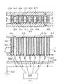
ドロップ・オン・デマンド型の印字装置に用いられるインク噴射装置として、例えば、特開昭63−247051号公報に記載の圧電材料を利用したせん断モード型がある。この種のインク噴射装置の一例を図6に示す。なお、図6(a)は図6(b)のA−A線断面に、図6(b)は図6(a)のB−B線断面に、それぞれ対応している。
【0004】
図6に示すように、インク噴射装置600は、底壁601,天壁602,およびその間のせん断モード型のアクチュエータ壁603からなる。そのアクチュエータ壁603は天壁602に接着され、かつ矢印609方向に分極された圧電材料製の上部壁605と、底壁601に接着され、かつ矢印611方向に分極された圧電材料製の下部壁607とからなっている。アクチュエータ壁603は一対となって、その間にインク室613を形成し、かつその隣の一対のアクチュエータ壁603との間には、インク室613よりも狭い空間615を形成している。
【0005】
各インク室613の一端には、ノズル618を有するノズルプレート617が固着され、他端には、マニホールド626を介して図示しないインク供給源が接続されている。なお、マニホールド626は、各インク室613に連通する開口部を有する前部壁627と、底壁601,天壁602の間を密閉する後部壁628とを備え、上記インク供給源から前部壁627,後部壁628の間に供給されたインクを、各インク室613に分配するものである。
【0006】
各アクチュエータ壁603の両側面には電極619,621が金属化層として設けられている。具体的にはインク室613側のアクチュエータ壁603には電極619が設けられ、空間615側のアクチュエータ壁603には電極621が設けられている。なお、電極619の表面はインクと絶縁するための絶縁層で覆われている。そして、空間615に面している電極621はアース623に接続され、インク室613内に設けられた電極619は制御装置625に接続され、後述のような電圧(駆動信号)を印加される。
【0007】
そして、各インク室613の電極619に制御装置625が電圧を印加することによって、各アクチュエータ壁603がインク室613の容積を増加する方向に圧電厚みすべり変形する。この動作の一例を図7に示す。なお、図7では、各部603〜619の符号に図の左側からa,b,c,…の添え字を付して、それぞれを区別している。図7に例示するように、インク室613cの電極619cに所定の電圧E(V)が印加されると、アクチュエータ壁603e,603fにそれぞれ矢印631,632の方向の電界が発生し、アクチュエータ壁603e,603fがインク室613cの容積を増加する方向に圧電厚みすべり変形する。このとき、ノズル618c付近を含むインク室613c内の圧力が減少する。
【0008】
この電圧E(V)の印加をインク室613内の圧力波の片道伝播時間Tだけ維持する。すると、その間に前述のインク供給源からインクが供給される。なお、上記片道伝播時間Tはインク室613内のインクの圧力波が、インク室613の長手方向に片道伝播する時間であり、インク室613の長さLとこのインク室613内部のインク中での音速aとによりT=L/aなる式で算出される。
【0009】
圧力波の伝播理論によると、上記電圧の印加から片道伝播時間Tが経過するとインク室613内の圧力が逆転し、正の圧力に転じるが、このタイミングに合わせてインク室613cの電極619cに印加されている電圧が0(V)に戻される。すると、アクチュエータ壁603e,603fが変形前の状態(図6)に戻りインクに圧力が加えられる。そのとき、上記正に転じた圧力とアクチュエータ壁603e,603fが変形前の状態に戻ることにより発生した圧力とが加え合わされ、比較的高い圧力がインク室613cのノズル618c付近の部分に生じて、インク滴がノズル618cから噴射される。また、この種のインク噴射装置600では、1ドットの印字命令に対して複数のインク滴を連続的に噴射し、記録用紙等の被記録媒体に濃厚で見やすい画像を形成することが考えられている。
【0010】
【発明が解決しようとする課題】
ところが、従来のインク噴射装置では、1ドットの印字命令に対して複数のインク滴を連続的に噴射しても、次のような場合、充分に濃厚な画像が形成できなかった。すなわち、上記噴射された複数のインク滴が、被記録媒体に到達するまでに一体化してしまった場合、飛翔中のインク滴はある程度大きくなるものの、被記録媒体に付着するとその大部分が被記録媒体に吸収されてしまう。このため、被記録媒体の表面から見たインク滴の大きさは、インク滴を1滴だけ噴射した場合と余り変わらないことがある。このような場合、インクの消費量は上記複数倍に増大するものの、画像は余り濃厚にならない。
【0011】
そこで、本発明は、複数のインク滴を噴射することにより濃厚な画像を良好に形成することができるインク噴射装置を提供することを目的としてなされた。
【0012】
【課題を解決するための手段および発明の効果】
上記目的を達するためになされた請求項1記載の発明は、インクを噴射するノズルと、
該ノズルの背後に設けられインクが充填されるインク室と、該インク室の容積を変化させるアクチュエータと、上記アクチュエータを駆動し、上記インク室の容積を一旦増加させた後上記インク室の容積を減少させて上記ノズルからインク滴を噴射する動作を、1ドットの印字命令に対して複数回繰り返す駆動手段と、を備え、被記録媒体に対して相対移動して、上記被記録媒体にドットで画像を形成するインク噴射装置であって、上記駆動手段が、上記1ドットの印字命令に対して複数回インク滴を噴射するための駆動信号を出力するに当たり、n回目に上記容積を増加させてからn回目に上記容積を減少させるまでの時間Wa、n回目に上記容積を減少させてからn+1回目に上記容積を増加させるまでの時間d1、および、n+1回目に上記容積を増加させてからn+1回目に上記容積を減少させるまでの時間Wbと、上記インク室内をインクの圧力波が片道伝播する片道伝播時間Tとの比の値が、次表に示す数値の±0.05の範囲に収まり、かつ、先の上記駆動信号によって上記インク室内に生じたインクの圧力波のピークに後の上記駆動信号によって生じるインクの圧力波のピークが重畳しないタイミングで、上記各駆動信号を出力し、しかも、上記インク室の容積の増加、減少により噴射された各インク滴が被記録媒体に到達するまでに一体化することなく、上記被記録媒体上に、その被記録媒体に対する相対移動に伴い相互に一部のみ重なってずれて付着するようにし、更に、上記駆動手段が、上記複数の噴射のための上記インク室の容積の増加、減少の後、上記インク室内の圧力波振動を相殺するために上記インク室の容積を増加、減少させることを特徴としている。
【表2】
このように構成された本発明では、1ドットの印字命令に対して複数のインク滴を連続的に噴射して、しかも、各インク滴が被記録媒体に到達するまでに一体化することなく被記録媒体上に相互にずれて付着するようにしている。各インク滴が被記録媒体に到達するまでに一体化せず、しかも、インク噴射装置は被記録媒体に対して相対移動するので、上記各インク滴の被記録媒体への付着位置は、上記相対移動の方向に沿って変位する。更に、本発明では、各インク滴が飛翔する間隔等を調整して、上記各インク滴が被記録媒体上に相互に一部のみ重なってずれて付着するようにしている。このため、被記録媒体の表面からみたインク滴の大きさは、インク滴を1滴だけ噴射した場合の上記複数倍に近い大きさとなる。従って、本発明では、複数のインク滴を噴射することにより濃厚な画像を良好に形成することができる。
【0014】
【0015】
また、本発明では、ノズルの背後に設けられたインク室の容積を一旦増加させた後、そのインク室の容積を減少させてノズルからインク滴を噴射する。すなわち、インク室の容積が増加するとその内部の圧力が一旦減少し、そのインク室内にインクが流入する。続いてインク室の容積を減少させることにより、インク室内に比較的高い圧力が生じ、インク滴がノズルから噴射されるのである。ここで、本発明の駆動手段は、この噴射動作を1ドットの印字命令に対して複数回繰り返す。このため、1ドットの印字命令に対して複数のインク滴が連続的に噴射される。
【0016】
インク室の容積を増減してインク滴を噴射する場合、n回目の駆動信号による上記圧力波のピークにn+1回目の駆動信号による上記圧力波のピークが重畳すると、n回目に噴射されたインク滴よりも高い圧力でn+1回目のインク滴が噴射される。すると、n+1回目に噴射されたインク滴が高速で飛翔し、n回目に噴射されたインク滴に追いついて一体化してしまう。
【0017】
これに対して、本発明では、上記ピークが重畳しないタイミングで駆動信号を出力しているので、各インク滴は一体化することなく被記録媒体に到達することができる。従って、本発明では、容易に前述のような濃厚な画像を形成することができる。
【0018】
なお、上記nは、1ドットの印字命令に対するインク滴の噴射数より小さい自然数であれば如何なる値でもよく、また、固定値ではなくてその都度変動する値であってもよい。
更に、本発明では、駆動手段が、上記噴射のためのインク室の容積の増加、減少の後、インク室の容積を増減させてインク室内の圧力波振動を相殺するので、その圧力波振動が早期に収束する。このため、インクが非所望に噴射されることがなく、次の印字命令に対する処理に早期に移行することもできる。従って、本発明では、上記効果に加えて、一層良好な画像を形成すると共に印字速度を向上させることができるといった効果も生じる。なお、上記相殺とは、圧力波振動を完全に解消するものではなくてもよく、例えば、インク滴が噴射されない程度に圧力波振動を抑制するものであってもよい。
請求項2記載の発明は、請求項1記載の構成に加え、上記ノズルと上記被記録媒体との距離が2mm以下であり、上記時間Wbが、上記片道伝播時間TまたはそのTの奇数倍と等しくないことを特徴としている。
【0019】
【0020】
【0021】
【0022】
【0023】
【0024】
請求項3記載の発明は、請求項1または2記載の構成に加え、上記駆動手段が上記1ドットの印字命令に対して3滴以上のインク滴を噴射することを特徴としている。
【0025】
【0026】
【0027】
請求項4記載の発明は、請求項1〜3のいずれかに記載の構成に加え、上記駆動手段が、上記アクチュエータに電圧を印加することにより上記インク室の容積を増加または減少させるものであって、しかも、上記電圧が一定値であることを特徴としている。
【0028】
このように、本発明では、上記アクチュエータとして電圧を印加することによりインク室の容積を増加または減少させるものを使用し、しかも、その電圧を一定値としたので、各駆動信号のための電源が1つでよく、駆動回路や制御回路の構成を簡略化することができる。また、アクチュエータの制御も、電圧を印加するかしないかの切り換えによって行われ、制御のための処理も簡単になる。従って、本発明では、請求項1〜3のいずれかに記載の発明の効果に加えて、装置の構成および制御を一層簡略化することができるといった効果が生じる。
【0029】
請求項5記載の発明は、請求項1〜4のいずれかに記載の構成に加え、上記アクチュエータが、上記インク室の側壁をなす圧電材料を用いて構成されていることを特徴としている。
本発明では、インク室の側壁をなす圧電材料を用いて上記アクチュエータが構成されているので、その圧電材料に電圧を印加して変形させることによってインク室の容積を変化させることができる。このようなアクチュエータは、構成が簡単で耐久性にも優れ、更に安価である。従って、本発明では、請求項1〜4のいずれかに記載の発明の効果に加えて、装置の構成を簡略化し、耐久性を向上させると共に、製造コストを一層低減することができるといった効果が生じる。
【0030】
【発明の実施の形態】
以下、本発明の実施の形態を図面に従って説明する。本実施の形態のインク噴射装置600における機械的部分の構成は、図6に示す従来のものと同様であるので説明を省略する。このインク噴射装置600の具体的な寸法を述べる。インク室613の長さLが7.5mmである。ノズル618の寸法は、ノズル面617a側の径が40μm、インク室613側の径が72μm、長さが100μmである。また、後述の実験に供したインクの25℃における粘度は約2mPa・s、表面張力は30mN/mである。このインク室613内のインク中における音速aと上記Lとの比L/a(=T)は8μsecである。更に、インク噴射装置600は図示しないプラテンに沿って移動するキャリッジに搭載され、ノズル面617aとプラテン上の記録媒体97(図5)との間隔は1〜2mmである。
【0031】
図1は、本実施の形態のインク噴射装置600に用いられた制御装置625の構成を表す回路図である。図1に示すように、制御装置625は、充電回路182,放電回路184,およびパルスコントロール回路186から構成されている。また、図1では、アクチュエータ壁603の圧電材料および電極619,621をコンデンサ191で表しており、そのコンデンサ191の端子191A,191Bはそれぞれ電極619,621に対応する。すなわち、端子191Aが制御装置625に、端子191Bがアース623に、それぞれ接続されている。
【0032】
充電回路182に設けられた入力端子187と放電回路184に設けられた入力端子188とは、それぞれインク室613内の電極619(端子191A)にE(V)の電圧(例えば20V)または0(V)の電圧を印加するためのパルス信号を、後述のパルスコントロール回路186から入力するための端子である。
【0033】
充電回路182は、抵抗R101,R102,R103,R104,R105、および、トランジスタTR101,TR102から構成されている。トランジスタTR101のベースは、抵抗R101を介して入力端子187に接続されると共に、抵抗R102を介して接地されている。トランジスタTR101のエミッタは直接接地され、コレクタは、E(V)の正の電源189に抵抗R103を介して接続されている。また、トランジスタTR102のベースは、抵抗R104を介して正の電源189に接続されると共に、抵抗R105を介してトランジスタTR101のコレクタに接続されている。トランジスタTR102のエミッタは正の電源189に直接接続され、コレクタは抵抗R120を介して端子191Aに接続されている。
【0034】
このため、入力端子187にオン信号(+5V)が入力されると、トランジスタTR101が導通し、正の電源189からの電流がトランジスタTR101のコレクタからエミッタ方向に流れる。従って、正の電源189に接続されている抵抗R104およびR105にかかる電圧の分圧が上昇し、トランジスタTR102のべースに流れる電流が増加し、トランジスタTR102のエミッタとコレクタ間が導通する。そして、正の電源189からのE(V)の電圧がトランジスタTR102のコレクタおよびエミッタ、抵抗R120を介してコンデンサ191の端子191Aに印加される。
【0035】
次に、放電回路184について説明する。放電回路184は抵抗R106,R107,トランジスタTR103から構成されている。トランジスタTR103のベースは、抵抗R106を介して入力端子188に接続されると共に、抵抗R107を介して接地されている。トランジスタTR103のエミッタは直接接地され、コレクタは、前述の抵抗R120を介して端子191Aに接続されている。このため、入力端子188にオン信号(+5V)が入力されるとトランジスタTR103が導通し、抵抗R120を介してコンデンサ191の端子191Aを接地する。
【0036】
次に、この充電回路182,放電回路184によってアクチュエータ壁603(コンデンサ191)に印加される電圧の変化を説明する。
充電回路182の入力端子187に入力される入力信号は、図2(A)のタイミングチャートに示すように、通常オフの状態にあり、インクの噴射時には後述の所定のタイミングT1にてオンされ、タイミングT2にてオフされる。その後、タイミングT3にてオンされ、タイミングT4にてオフされ、更にタイミングT5にてオンされ、タイミングT6にてオフされる。放電回路184の入力端子188に入力される入力信号は、図2(B)のタイミングチャートに示すように、入力端子187の入力信号がオンされるとき(T1,T3,T5)オフされ、入力端子187の入力信号がオフされるとき(T2,T4,T6)オンされる。
【0037】
この場合、コンデンサ191の端子191Aに印加される電圧は、図2(C)に示すように、通常は0(V)に維持されているが、タイミングT1にて、コンデンサ191すなわちアクチュエータ壁603へ電荷が充電され、トランジスタTR102と、抵抗R120と、せん断モード型圧電素子からなるアクチュエータ壁603の静電容量とにて決まる充電時間Ta後に電圧E(V)になる。またタイミングT2にて、トランジスタTR103と、抵抗R120と、アクチュエータ壁603の静電容量とにて決まる放電時間Tb後に0(V)になる。
【0038】
このように電極619(端子191A)に実際に印加される電圧(以下、駆動信号という)の波形は、立ち上がりと立ち下がりでそれぞれTa、Tbの遅れが生じるため、電圧が1/2E(V)(例えば10V)となる時点を、駆動信号の立ち上がりタイミング(AS,BS,HS)および立ち下がりタイミング(AE,BE,HE)として近似する。パルスコントロール回路186は、この駆動信号の立ち上がりおよび立ち下がりが後述のタイミングとなるように、入力端子187,188への入力信号の上記タイミングT1〜T6等を制御する回路である。次に、図1に戻ってパルスコントロール回路186の構成について説明する。
【0039】
パルスコントロール回路186には、各種の演算処理を行うCPU210が設けられ、そのCPU210には、印字データや各種のデータを記憶するRAM212と、パルスコントロール回路186の制御プログラムおよび前述のタイミングT1〜T6でオン,オフ信号を発生するシーケンスデータを記憶するROM214とが接続されている。ここで、ROM214には、図3に示すように、インク噴射装置制御プログラム記憶エリア214Aと、駆動波形データ記憶エリア214Bとが設けられている。従って、前述の駆動信号の波形に関するシーケンスデータは、駆動波形データ記憶エリア214Bに記憶されている。
【0040】
更に、CPU210は各種のデータのやりとりをするI/Oバス216に接続され、当該I/Oバス216には、印字データ受信回路218とパルスジェネレータ220および222が接続されている。パルスジェネレータ220の出力は充電回路182の入力端子187に入力され、パルスジェネレータ222の出力は放電回路184の入力端子188に入力されている。
【0041】
CPU210はROM214の駆動波形データ記憶エリア214Bに記憶されているシーケンスデータに従って、パルスジェネレータ220および222を制御する。従って、上記タイミングT1〜T6の各種パターンを予めROM214内の駆動波形データ記憶エリア214Bに記憶させておくことによって、1ドットの印字命令に対して、所望の波形の駆動信号をアクチュエータ壁603に与えることができる。なお、パルスジェネレータ220,222、充電回路182、および放電回路184は、インク噴射装置600のノズル618と同じ数だけ設けられている。CPU210は、印字データに応じたアクチュエータ壁603に駆動信号を出力し、対応するノズル618からインクを噴射する。
【0042】
次に、本実施の形態のインク噴射装置600における、上記駆動信号の波形(以下、駆動波形という)の一例を図4(A)に例示する。また、図4(B)はその駆動波形に応じたインク室613内の圧力の変化を表している。なお、インク噴射装置600は、キャリッジによって移動されている途中でこれらの駆動信号を出力する。図4に示すように、本例の駆動波形は、インク滴99(図5)を噴射するための二つの噴射パルス信号A、Bと上記インク室613内に残留した圧力波振動を相殺するための非噴射パルス信号Cとからなり、噴射パルス信号A、Bと非噴射パルス信号Cのどちらも波高値(電圧値)はE(V)である。
【0043】
タイミングASで噴射パルス信号Aが立ち上がると、図7にてインク室613cを例に説明したように、アクチュエータ壁603に電界が発生し、インク室613の容積が増大してノズル618付近を含むインク室613内の圧力が減少する。その後、インク室613にはインクが流入する一方、容積の増大によって生じた圧力波振動による圧力が増加して正の圧力に転じ、片道伝播時間Tを経過する時点でピークに達する。この時点近傍のタイミングAEで噴射パルス信号Aが立ち下がるとインク室613の容積が減少するが、そのことにより発生した圧力と、上記正に転じた圧力とが加え合わされ、比較的高い圧力がインク室613のノズル618付近の部分に生じて、インク滴99がノズル618から噴射される。
【0044】
続いて、タイミングAEから所定時間d1経過したタイミングBS(インク室613の圧力が正から負に転じた後のタイミング)にて噴射パルス信号Bが立ち上がり、片道伝播時間Tを経過する時点近傍のタイミングBEにて噴射パルス信号Bが立ち下がると、同様にして2滴目のインク滴99がノズル618から噴射される。
【0045】
更に、その後、インク室613の圧力が正から負に転じる前のタイミングHSにて、非噴射パルス信号Cが立ち上がり、負に転じた後のタイミングHEで非噴射パルス信号Cが立ち下がる。すると、タイミングHSでは、未だ正である上記圧力が急減し、タイミングHEでは、負に転じた上記圧力が急増する。このため、上記圧力波の振動が相殺され、その振動が急速に収束に向かう。また、非噴射パルス信号Cは上記圧力波振動を相殺するので、このパルスが発生してもインクは噴射されない。このように圧力波振動が相殺されるとインクが非所望に噴射されることが防止され、次の印字命令に対する処理に早期に移行することもできる。従って、一層良好な画像を形成すると共に印字速度を向上させることができる。
【0046】
このように、本実施の形態のインク噴射装置600では、1ドットの印字命令に対して2滴のインク滴99を連続的に噴射しているので、1滴のインク滴99を噴射する場合に比べて、記録媒体97に濃厚で見やすい画像を形成することができる。ところが、上記噴射された2滴のインク滴99が、記録媒体97に到達するまでに一体化してしまった場合、充分に濃厚な画像が形成できない。
【0047】
図5(A)は、一体化した後に記録媒体97に付着したインク滴99を例示する平面図であり、図5(B)はその側面図である。図5(A),(B)に例示するように、インク滴99が記録媒体97に到達するまでに一体化してしまった場合、飛翔中のインク滴99はある程度大きくなるものの、記録媒体97に付着するとその大部分99aが記録媒体97に吸収されてしまう。このため、記録媒体97の表面から見たインク滴99の大きさは、インク滴99を1滴だけ噴射した場合と余り変わらないことがある。
【0048】
そこで、本発明者は、前述の所定時間d1の他、タイミングBEからタイミングHS,HEの中心に到るまでの時間d2、および、パルス信号A,B,Cのパルス幅Wa,Wb,Wcを適宜設定して、インク滴99が記録媒体97に到達するまでに一体化しないようにすることを考えた。先ず、Wa,Wb,d1の全てが片道伝播時間Tに等しいかそのTの奇数倍であると、インクの圧力波振動の振幅が徐々に大きくなる。すると、後から噴射されたインク滴99ほど高速で飛翔し、先に噴射されたインク滴99に追いついて一体化してしまう。そこで、Wa,Wb,d1の少なくともいずれか一つが、片道伝播時間TまたはそのTの奇数倍と一致しないようにして、インク滴99が記録媒体97に到達するまでにインク滴99の一体化を防止し、キャリッジと記録媒体97の相対移動に伴い図5(C)(D)のように複数のインク滴99が記録媒体97上で相互にずれるように記録することが考えられる。
【0049】
また、基本的な原理は同じであるが、噴射パルス信号Aによって生じるインクの圧力波振動(圧力波)のピークに、噴射パルス信号Bによって生じるインクの圧力波振動のピークが重畳すると、先に噴射されたインク滴99よりも高い圧力で後のインク滴99が噴射される。すると、後から噴射されたインク滴99ほど高速で飛翔し、先に噴射されたインク滴99に追いついて一体化してしまう。そこで、噴射パルスA,Bによって生じるインクの圧力波振動のピークが互いに重畳しないタイミングで噴射パルス信号Bを出力して、上記一体化を防止することも考えられる。
【0050】
以上の考察の元にWa,d1,Wb,d2,Wcの値を種々に設定して実験を行い、インク滴99の一体化を良好に防止することができると共に、インク滴99噴射後の圧力波振動を良好に相殺することができる値を求めた、結果を表3に示す。なお、表3では、上記各値を片道伝播時間Tとの比の値で表した。
【0051】
【表3】
Wa,d1,Wb,d2,Wcの値を表3に示す値に設定した場合、インク滴99が記録媒体97に到達するまでに一体化するのを確実に防止することができ、また、キャリッジが記録媒体97に対して移動するのに伴い2滴のインク滴99の付着位置が相互にずれ、図5(C),(D)に平面図,側面図を例示するように、記録媒体97上で2滴のインク滴99が一部のみ重なるようにすることができた。このため、記録媒体97に吸収される部分99aも少なく、記録媒体97の表面からみたインク滴99の大きさも2倍近くなった。従って、記録媒体97に濃厚な画像を良好に形成することができた。また、Wa,d1,Wb,d2,Wcの値を上記値に設定したことにより、インクの圧力波振動が早期に収束して、インクが非所望に噴射されることもなく次の印字命令に対する処理に早期に移行することもできた。従って、きわめて良好な画像を形成すると共に印字速度を向上させることができた。
【0053】
2滴のインク滴99のずれ量は、キャリッジの移動速度、インク滴99の噴射速度、d1の値等で、任意に決定することができる。
なお、Wa,d1,Wb,d2,Wcの値は上記値に厳密に一致しなくてもよく、±0.05(×T)程度の誤差があっても上記効果が同様に生じることが判明した。また、本願出願人による実験では表3に示す値が適切と考えられたが、表3に示す値以外にも適切な値が存在する可能性がある。特に、ノズル面617aと記録媒体97との間隔等、各種実験条件を変更した場合、表3に示す値以外に適切な値が存在することが充分に考えられる。
【0054】
なお、上記実施の形態において、アクチュエータ壁603および電極619,621がアクチュエータに、制御装置625が駆動手段に、記録媒体97が被記録媒体に、それぞれ相当する。また、本発明は上記実施の形態になんら限定されるものではなく、本発明の要旨を逸脱しない範囲で種々の形態で実施することができる。例えば、上記実施の形態では1ドットの印字命令に対して2滴のインク滴99を噴射しているが、3滴以上のインク滴99を噴射してもよい。この場合も、そのインク滴99の少なくとも二つが一体化しないようにすることにより、濃厚な画像を良好に形成することができる。
【0055】
また、噴射パルス信号Bまたは非噴射パルス信号CとしてE(V)より低い電圧を印加することにより、後から噴射されたインク滴99が先に噴射されたインク滴99に追いつかないようにしたり、圧力波振動の相殺時にインクが噴射されないようにしたりすることもできる。但し、上記実施の形態では、パルス信号A,B,Cの電圧を一定値とし、その出力タイミングAS〜HEを調整することにより上記一体化の防止および圧力波振動の相殺を行っているので、各パルス信号を出力するための電源が1つでよく、装置の構成および制御をきわめて簡略化することができる。
【0056】
更に、本発明は、圧電材料を用いて構成されたアクチュエータ以外の手段によってインクを噴射する装置、印字装置本体にインク噴射装置600を固定したいわゆるラインプリンタ等にも適用することができる。但し、上記実施の形態のように圧電材料を用いたアクチュエータを使用する場合、装置の構成を一層簡略化し、耐久性を向上させると共に、製造コストを一層低減することができる。なお、ラインプリンタの場合、記録媒体を搬送しながら複数のインク滴を噴射することにより、各インク滴が記録媒体上で一部のみ重なった濃厚な画像が形成可能となる。
【図面の簡単な説明】
【図1】 本発明が適用されたインク噴射装置の制御装置の構成を表す回路図である。
【図2】 その制御装置の充電回路,放電回路の動作を表すタイミングチャートである。
【図3】 その制御装置のROMの構成を表す説明図である。
【図4】 その制御装置が出力するインク噴射装置の駆動波形を例示する説明図である。
【図5】 その駆動波形による記録媒体へのインク滴の付着状態を表す説明図である。
【図6】 従来技術および本発明に関わるインク噴射装置の構成を表す断面図である。
【図7】 そのインク噴射装置の動作の一例を表す説明図である。
【符号の説明】
97…記録媒体 99…インク滴 182…充電回路 184…放電回路
186…パルスコントロール回路 600…インク噴射装置
603…アクチュエータ壁 613…インク室 618…ノズル
619,621…電極 625…制御装置[0001]
BACKGROUND OF THE INVENTION
The present invention relates to an ink ejecting apparatus that ejects ink from a nozzle in response to a print command to form an image on a recording medium.
[0002]
[Prior art]
Today, instead of conventional impact printing devices, the non-impact printing devices that are expanding the market greatly have the simplest principle, and are easy to achieve multi-gradation and colorization. As an example, there is an ink jet type printing apparatus. Among them, a drop-on-demand type that ejects only ink droplets used for printing is rapidly spreading due to its good ejection efficiency and low running cost.
[0003]
As an ink ejecting apparatus used for a drop-on-demand type printing apparatus, for example, there is a shear mode type using a piezoelectric material described in JP-A-63-247051. An example of this type of ink ejecting apparatus is shown in FIG. 6A corresponds to a cross section taken along line AA in FIG. 6B, and FIG. 6B corresponds to a cross section taken along line BB in FIG. 6A.
[0004]
As shown in FIG. 6, the
[0005]
A
[0006]
[0007]
Then, when the
[0008]
The application of the voltage E (V) is maintained for the one-way propagation time T of the pressure wave in the
[0009]
According to the pressure wave propagation theory, when the one-way propagation time T elapses from the application of the voltage, the pressure in the
[0010]
[Problems to be solved by the invention]
However, in the conventional ink ejecting apparatus, even if a plurality of ink droplets are ejected continuously in response to a one-dot printing command, a sufficiently dense image cannot be formed in the following cases. That is, when the plurality of ejected ink droplets are integrated by the time they reach the recording medium, the flying ink droplets will increase to some extent, but most of them will adhere to the recording medium. It is absorbed by the medium. For this reason, the size of the ink droplets viewed from the surface of the recording medium may not be much different from the case where only one ink droplet is ejected. In such a case, although the amount of ink consumption increases to a multiple of the above, the image does not become very thick.
[0011]
Accordingly, an object of the present invention is to provide an ink ejecting apparatus that can favorably form a dense image by ejecting a plurality of ink droplets.
[0012]
[Means for Solving the Problems and Effects of the Invention]
The invention according to claim 1, which has been made to achieve the above object, includes a nozzle for ejecting ink,
An ink chamber provided behind the nozzle and filled with ink, an actuator for changing the volume of the ink chamber, and the actuator is driven to increase the volume of the ink chamber, and then the volume of the ink chamber is reduced. Driving means that repeats the operation of ejecting ink droplets from the nozzles in a reduced manner a plurality of times in response to a one-dot print command, and moves relative to the recording medium so that the dots are formed on the recording medium. An ink ejecting apparatus for forming an image, wherein when the driving means outputs a driving signal for ejecting ink droplets a plurality of times in response to the one-dot printing command, the volume is increased at the nth time. From time to time n until the volume is decreasedA time d1 from the time when the volume is decreased n times until the volume is increased n + 1 times, and a time Wb from the time when the volume is increased n + 1 times to the time when the volume is decreased n + 1 times,One-way propagation time T for one-way propagation of ink pressure wave in the ink chamberThe value of the ratio is ± 0.05 of the value shown in the following tableWithin the range ofThe peak of the pressure wave of the ink generated in the ink chamber by the previous driving signal isAt the timing when the pressure wave peak of the ink generated by the drive signal does not overlap, the aboveeachOutput drive signal,Moreover,The ink droplets ejected due to the increase or decrease in the volume of the ink chamber are not integrated with each other until reaching the recording medium. And the driving means is further configured to cancel the pressure wave vibration in the ink chamber after the increase or decrease in the volume of the ink chamber for the plurality of ejections. It is characterized by increasing or decreasing the volume of the ink chamber.
[Table 2]
In the present invention configured as described above, a plurality of ink droplets are continuously ejected in response to a 1-dot printing command, and the ink droplets are not integrated before reaching the recording medium. The recording medium is attached so as to be shifted from each other. The ink droplets are not integrated by the time they reach the recording medium, and the ink ejecting apparatus moves relative to the recording medium. Displacement along the direction of movement. Further, according to the present invention, the intervals at which the ink droplets fly are adjusted so that the ink droplets partially adhere to each other on the recording medium. For this reason, the size of the ink droplets as viewed from the surface of the recording medium is close to the above multiple size when only one ink droplet is ejected. Therefore, in the present invention, a dense image can be formed favorably by ejecting a plurality of ink droplets.
[0014]
[0015]
In the present invention, the volume of the ink chamber provided behind the nozzle is once increased, and then the volume of the ink chamber is decreased to eject ink droplets from the nozzle. That is, when the volume of the ink chamber increases, the pressure inside the ink chamber once decreases, and the ink flows into the ink chamber. Subsequently, by reducing the volume of the ink chamber, a relatively high pressure is generated in the ink chamber, and ink droplets are ejected from the nozzles. Here, the driving means of the present invention repeats this ejection operation a plurality of times for a one-dot print command. For this reason, a plurality of ink droplets are continuously ejected in response to a one-dot printing command.
[0016]
When ejecting ink droplets by increasing or decreasing the volume of the ink chamber, if the pressure wave peak due to the (n + 1) th driving signal is superimposed on the pressure wave peak due to the nth driving signal, the ink droplet ejected at the nth time The n + 1th ink droplet is ejected at a pressure higher than that. Then, the ink droplet ejected at the (n + 1) th time flies at a high speed, catches up with the ink droplet ejected at the nth time, and is integrated.
[0017]
On the other hand, in the present invention, since the drive signal is output at a timing at which the above peaks do not overlap, each ink droplet can reach the recording medium without being integrated. Therefore, in the present invention, it is possible to easily form a rich image as described above.
[0018]
Note that n may be any value as long as it is a natural number smaller than the number of ink droplets ejected for a one-dot print command, and may be a value that varies each time instead of a fixed value.
Furthermore, in the present invention, the drive means increases or decreases the volume of the ink chamber after the increase or decrease of the volume of the ink chamber for ejection, so that the pressure wave vibration in the ink chamber is canceled out. Converge early. For this reason, the ink is not ejected undesirably, and the process for the next print command can be shifted to an early stage. Therefore, in the present invention, in addition to the above effects, there is an effect that a better image can be formed and the printing speed can be improved. The canceling may not completely eliminate the pressure wave vibration, and may suppress the pressure wave vibration to such an extent that an ink droplet is not ejected, for example.
According to a second aspect of the present invention, in addition to the configuration of the first aspect, a distance between the nozzle and the recording medium is 2 mm or less.Time Wb is not equal to the one-way propagation time T or an odd multiple of TIt is characterized by that.
[0019]
[0020]
[0021]
[0022]
[0023]
[0024]
According to a third aspect of the present invention, in addition to the configuration of the first or second aspect, the driving unit ejects three or more ink droplets in response to the one-dot print command.
[0025]
[0026]
[0027]
According to a fourth aspect of the present invention, in addition to the configuration according to any one of the first to third aspects, the drive means increases or decreases the volume of the ink chamber by applying a voltage to the actuator. In addition, the voltage is a constant value.
[0028]
As described above, in the present invention, the actuator that increases or decreases the volume of the ink chamber by applying a voltage is used, and the voltage is set to a constant value. One may be sufficient and the structure of a drive circuit or a control circuit can be simplified. The actuator is also controlled by switching whether or not to apply a voltage, and the control process is simplified. Therefore, in the present invention, in addition to the effect of the invention according to any one of claims 1 to 3, an effect that the configuration and control of the apparatus can be further simplified is produced.
[0029]
According to a fifth aspect of the present invention, in addition to the structure according to any one of the first to fourth aspects, the actuator is configured using a piezoelectric material forming a side wall of the ink chamber.
In the present invention, the actuator is configured using the piezoelectric material forming the side wall of the ink chamber. Therefore, the volume of the ink chamber can be changed by applying a voltage to the piezoelectric material to deform it. Such an actuator is simple in structure, excellent in durability, and inexpensive. Therefore, in the present invention, in addition to the effects of the invention according to any one of claims 1 to 4, the structure of the apparatus is simplified, the durability is improved, and the manufacturing cost can be further reduced. Arise.
[0030]
DETAILED DESCRIPTION OF THE INVENTION
Hereinafter, embodiments of the present invention will be described with reference to the drawings. The configuration of the mechanical part in the
[0031]
FIG. 1 is a circuit diagram illustrating a configuration of a
[0032]
An
[0033]
The charging circuit 182 includes resistors R101, R102, R103, R104, R105 and transistors TR101, TR102. The base of the transistor TR101 is connected to the
[0034]
For this reason, when an ON signal (+5 V) is input to the
[0035]
Next, the discharge circuit 184 will be described. The discharge circuit 184 includes resistors R106 and R107 and a transistor TR103. The base of the transistor TR103 is connected to the
[0036]
Next, changes in the voltage applied to the actuator wall 603 (capacitor 191) by the charging circuit 182 and the discharging circuit 184 will be described.
As shown in the timing chart of FIG. 2A, the input signal input to the
[0037]
In this case, the voltage applied to the terminal 191A of the
[0038]
Thus, the waveform of the voltage actually applied to the electrode 619 (terminal 191A) (hereinafter referred to as drive signal) has a delay of Ta and Tb at the rise and fall, respectively, so the voltage is 1 / 2E (V). The time point (for example, 10V) is approximated as the drive signal rise timing (AS, BS, HS) and fall timing (AE, BE, HE). The pulse control circuit 186 is a circuit for controlling the timings T1 to T6 of the input signals to the
[0039]
The pulse control circuit 186 is provided with a
[0040]
Further, the
[0041]
The
[0042]
Next, FIG. 4A illustrates an example of a waveform of the drive signal (hereinafter referred to as a drive waveform) in the
[0043]
When the ejection pulse signal A rises at the timing AS, as described in the
[0044]
Subsequently, the timing near the time point when the ejection pulse signal B rises and the one-way propagation time T elapses at a timing BS (a timing after the pressure in the
[0045]
Further, thereafter, the non-ejection pulse signal C rises at a timing HS before the pressure in the
[0046]
As described above, in the
[0047]
FIG. 5A is a plan view illustrating
[0048]
Therefore, the present inventor determines the time d2 from the timing BE to the center of the timing HS, HE and the pulse widths Wa, Wb, Wc of the pulse signals A, B, C in addition to the predetermined time d1 described above. It was considered that the
[0049]
Although the basic principle is the same, when the peak of the pressure wave vibration of the ink generated by the ejection pulse signal B is superimposed on the peak of the pressure wave vibration (pressure wave) of the ink generated by the ejection pulse signal A, The
[0050]
Based on the above consideration, the experiment is performed by setting various values of Wa, d1, Wb, d2, and Wc, and the integration of the
[0051]
[Table 3]
Table of values of Wa, d1, Wb, d2, Wc3When the
[0053]
The deviation amount of the two
It should be noted that the values of Wa, d1, Wb, d2, and Wc do not have to exactly match the above values, and it has been found that the above-mentioned effect is similarly produced even if there is an error of about ± 0.05 (× T). did. In the experiments by the applicant,3The values shown in3There is a possibility that an appropriate value other than the value shown in FIG. In particular, when various experimental conditions such as the distance between the
[0054]
In the above embodiment, the
[0055]
Further, by applying a voltage lower than E (V) as the ejection pulse signal B or the non-ejection pulse signal C, the
[0056]
Furthermore, the present invention provides, PressureThe present invention can also be applied to a device that ejects ink by means other than an actuator configured using an electric material, a so-called line printer in which the
[Brief description of the drawings]
FIG. 1 is a circuit diagram illustrating a configuration of a control device of an ink ejecting apparatus to which the invention is applied.
FIG. 2 is a timing chart showing operations of a charging circuit and a discharging circuit of the control device.
FIG. 3 is an explanatory diagram showing a configuration of a ROM of the control device.
FIG. 4 is an explanatory diagram illustrating drive waveforms of the ink ejecting apparatus output by the control device.
FIG. 5 is an explanatory diagram showing the state of ink droplets adhering to a recording medium according to the drive waveform.
FIG. 6 is a cross-sectional view illustrating a configuration of an ink ejecting apparatus according to the related art and the present invention.
FIG. 7 is an explanatory diagram illustrating an example of the operation of the ink ejecting apparatus.
[Explanation of symbols]
97: Recording medium 99 ... Ink droplet 182 ... Charging circuit 184 ... Discharging circuit
186 ...
603 ...
619, 621 ...
Claims (5)
Translated fromJapanese該ノズルの背後に設けられインクが充填されるインク室と、
該インク室の容積を変化させるアクチュエータと、
上記アクチュエータを駆動し、上記インク室の容積を一旦増加させた後上記インク室の容積を減少させて上記ノズルからインク滴を噴射する動作を、1ドットの印字命令に対して複数回繰り返す駆動手段と、
を備え、被記録媒体に対して相対移動して、上記被記録媒体にドットで画像を形成するインク噴射装置であって、
上記駆動手段が、上記1ドットの印字命令に対して複数回インク滴を噴射するための駆動信号を出力するに当たり、n回目に上記容積を増加させてからn回目に上記容積を減少させるまでの時間Wa、n回目に上記容積を減少させてからn+1回目に上記容積を増加させるまでの時間d1、および、n+1回目に上記容積を増加させてからn+1回目に上記容積を減少させるまでの時間Wbと、上記インク室内をインクの圧力波が片道伝播する片道伝播時間Tとの比の値が、次表に示す数値の±0.05の範囲に収まり、
かつ、先の上記駆動信号によって上記インク室内に生じたインクの圧力波のピークに後の上記駆動信号によって生じるインクの圧力波のピークが重畳しないタイミングで、上記各駆動信号を出力し、
しかも、上記インク室の容積の増加、減少により噴射された各インク滴が被記録媒体に到達するまでに一体化することなく、上記被記録媒体上に、その被記録媒体に対する相対移動に伴い相互に一部のみ重なってずれて付着するようにし、
更に、上記駆動手段が、上記複数の噴射のための上記インク室の容積の増加、減少の後、上記インク室内の圧力波振動を相殺するために上記インク室の容積を増加、減少させることを特徴とするインク噴射装置。
An ink chamber provided behind the nozzle and filled with ink;
An actuator for changing the volume of the ink chamber;
Driving means for driving the actuator to once increase the volume of the ink chamber and then decreasing the volume of the ink chamber and ejecting ink droplets from the nozzle a plurality of times in response to a one-dot print command When,
An ink ejecting apparatus that forms an image with dots on the recording medium by moving relative to the recording medium,
When the drive means outputs a drive signal for ejecting ink droplets a plurality of times in response to the 1-dot print command, the drive means increases the volume at the nth time and decreases the volume at the nth time. Time Wa, time d1 from the time when the volume is decreased n times to time when the volume is increased n + 1 times, and time Wb from time when the volume is increased n + 1 times to time when the volume is decreased n + 1 times Andthe ratio of the one-way propagation time T inwhich the pressure wave of the ink propagates one way in the ink chamber falls within a rangeof ± 0.05 of thenumerical value shown in the following table ,
Andeach said drive signal is output at the timing when the peak of the pressure wave of the ink generated by thesubsequent drive signal does not overlapthe peak of the pressure wave of the ink generated in the ink chamber by the previous drive signal ,
In addition, the ink droplets ejected due to the increase or decrease in the volume of the ink chamber do not integrate until reaching the recording medium, and the mutual movement of the ink droplets relative to the recording medium occurs on the recording medium. So that only part of it overlaps and adheres,
Further, the drive means increases or decreases the volume of the ink chamber in order to cancel pressure wave vibration in the ink chamber after the increase or decrease of the volume of the ink chamber for the plurality of ejections. An ink ejecting apparatus.
Priority Applications (3)
| Application Number | Priority Date | Filing Date | Title |
|---|---|---|---|
| JP11274697AJP3940462B2 (en) | 1997-04-30 | 1997-04-30 | Ink jet device |
| US09/069,776US6412927B1 (en) | 1997-04-30 | 1998-04-30 | Ink ejection device for forming high density dot image by successively ejecting two or more ink droplets |
| US09/069,776US20020089575A1 (en) | 1997-04-30 | 1998-04-30 | Ink ejection device for forming high density dot image by successively ejecting two or more ink droplets |
Applications Claiming Priority (1)
| Application Number | Priority Date | Filing Date | Title |
|---|---|---|---|
| JP11274697AJP3940462B2 (en) | 1997-04-30 | 1997-04-30 | Ink jet device |
Publications (2)
| Publication Number | Publication Date |
|---|---|
| JPH10296976A JPH10296976A (en) | 1998-11-10 |
| JP3940462B2true JP3940462B2 (en) | 2007-07-04 |
Family
ID=14594523
Family Applications (1)
| Application Number | Title | Priority Date | Filing Date |
|---|---|---|---|
| JP11274697AExpired - Fee RelatedJP3940462B2 (en) | 1997-04-30 | 1997-04-30 | Ink jet device |
Country Status (2)
| Country | Link |
|---|---|
| US (2) | US20020089575A1 (en) |
| JP (1) | JP3940462B2 (en) |
Families Citing this family (5)
| Publication number | Priority date | Publication date | Assignee | Title |
|---|---|---|---|---|
| US6523923B2 (en)* | 2000-10-16 | 2003-02-25 | Brother Kogyo Kabushiki Kaisha | Wavefrom prevents ink droplets from coalescing |
| JP4764038B2 (en)* | 2005-03-17 | 2011-08-31 | 東芝テック株式会社 | Driving method of ink jet recording apparatus |
| JP4313388B2 (en)* | 2006-10-11 | 2009-08-12 | 東芝テック株式会社 | Ink jet recording apparatus driving method and driving apparatus |
| JP5867072B2 (en)* | 2011-12-27 | 2016-02-24 | コニカミノルタ株式会社 | Droplet ejection device and method for driving droplet ejection device |
| JP6307945B2 (en)* | 2014-03-07 | 2018-04-11 | 株式会社リコー | Liquid ejection apparatus and liquid ejection head driving method |
Family Cites Families (11)
| Publication number | Priority date | Publication date | Assignee | Title |
|---|---|---|---|---|
| US5202659A (en)* | 1984-04-16 | 1993-04-13 | Dataproducts, Corporation | Method and apparatus for selective multi-resonant operation of an ink jet controlling dot size |
| CA1259853A (en)* | 1985-03-11 | 1989-09-26 | Lisa M. Schmidle | Multipulsing method for operating an ink jet apparatus for printing at high transport speeds |
| US5003679A (en) | 1987-01-10 | 1991-04-02 | Xaar Limited | Method of manufacturing a droplet deposition apparatus |
| US4992808A (en) | 1987-01-10 | 1991-02-12 | Xaar Limited | Multi-channel array, pulsed droplet deposition apparatus |
| US4879568A (en) | 1987-01-10 | 1989-11-07 | Am International, Inc. | Droplet deposition apparatus |
| US5621447A (en)* | 1991-10-25 | 1997-04-15 | Canon Kabushiki Kaisha | Jet recording method |
| JP3339724B2 (en)* | 1992-09-29 | 2002-10-28 | 株式会社リコー | Ink jet recording method and apparatus |
| ATE177996T1 (en)* | 1993-07-30 | 1999-04-15 | Canon Kk | INKJET PRINTING APPARATUS AND INKJET PRINTING METHOD |
| US5790152A (en)* | 1994-04-12 | 1998-08-04 | Xerox Corporation | Thermal ink-jet printhead for creating spots of selectable sizes |
| JPH0890777A (en) | 1994-09-26 | 1996-04-09 | Brother Ind Ltd | Ink jet recording device |
| JP3273716B2 (en) | 1995-08-29 | 2002-04-15 | ブラザー工業株式会社 | Ink ejecting apparatus and driving method thereof |
- 1997
- 1997-04-30JPJP11274697Apatent/JP3940462B2/ennot_activeExpired - Fee Related
- 1998
- 1998-04-30USUS09/069,776patent/US20020089575A1/enactiveGranted
- 1998-04-30USUS09/069,776patent/US6412927B1/ennot_activeExpired - Lifetime
Also Published As
| Publication number | Publication date |
|---|---|
| JPH10296976A (en) | 1998-11-10 |
| US20020089575A1 (en) | 2002-07-11 |
| US6412927B1 (en) | 2002-07-02 |
Similar Documents
| Publication | Publication Date | Title |
|---|---|---|
| JP3842886B2 (en) | Ink droplet ejection method and apparatus | |
| JP3557883B2 (en) | Method and apparatus for ejecting ink droplets | |
| US5736994A (en) | Ink-jet apparatus and driving method thereof | |
| JP3713958B2 (en) | Ink jet device | |
| US6527354B2 (en) | Satellite droplets used to increase resolution | |
| JPH11227203A (en) | Method and apparatus for ejecting ink droplets | |
| JP3909940B2 (en) | Ink droplet ejection method and apparatus | |
| JPH11334068A (en) | Ink jet device | |
| US5880750A (en) | Ink-jet apparatus having a preliminary pulse signal and a jet pulse signal and a driving method thereof | |
| US6254213B1 (en) | Ink droplet ejecting method and apparatus | |
| US6141113A (en) | Ink droplet ejection drive method and apparatus using ink-nonemission pulse after ink-emission pulse | |
| JP3738548B2 (en) | Ink droplet ejection method and apparatus | |
| JP4158310B2 (en) | Ink ejecting apparatus driving method and apparatus | |
| JP4491907B2 (en) | Ink droplet ejection method, control device therefor, and storage medium | |
| JP3940462B2 (en) | Ink jet device | |
| JP3687486B2 (en) | Ink droplet ejection method and apparatus and storage medium | |
| JP2000052561A (en) | Ink jet device | |
| US6260959B1 (en) | Ink ejector | |
| JP3654299B2 (en) | Ink droplet ejection device | |
| JP3290084B2 (en) | Method and apparatus for ejecting ink droplets | |
| JP3551822B2 (en) | Driving method of ink ejecting apparatus and apparatus therefor | |
| JP4432201B2 (en) | Ink ejection apparatus driving method, control apparatus, and storage medium | |
| US5521618A (en) | Dual element switched digital drive system for an ink jet printhead | |
| JP3249719B2 (en) | Ink ejecting apparatus and driving method thereof | |
| JP3290057B2 (en) | Ink ejecting apparatus and driving method thereof |
Legal Events
| Date | Code | Title | Description |
|---|---|---|---|
| A131 | Notification of reasons for refusal | Free format text:JAPANESE INTERMEDIATE CODE: A131 Effective date:20040106 | |
| A521 | Written amendment | Free format text:JAPANESE INTERMEDIATE CODE: A523 Effective date:20040308 | |
| A02 | Decision of refusal | Free format text:JAPANESE INTERMEDIATE CODE: A02 Effective date:20040420 | |
| A521 | Written amendment | Free format text:JAPANESE INTERMEDIATE CODE: A523 Effective date:20040621 | |
| A911 | Transfer of reconsideration by examiner before appeal (zenchi) | Free format text:JAPANESE INTERMEDIATE CODE: A911 Effective date:20040709 | |
| A912 | Removal of reconsideration by examiner before appeal (zenchi) | Free format text:JAPANESE INTERMEDIATE CODE: A912 Effective date:20040806 | |
| A521 | Written amendment | Free format text:JAPANESE INTERMEDIATE CODE: A523 Effective date:20070215 | |
| A61 | First payment of annual fees (during grant procedure) | Free format text:JAPANESE INTERMEDIATE CODE: A61 Effective date:20070402 | |
| R150 | Certificate of patent or registration of utility model | Free format text:JAPANESE INTERMEDIATE CODE: R150 | |
| FPAY | Renewal fee payment (event date is renewal date of database) | Free format text:PAYMENT UNTIL: 20100406 Year of fee payment:3 | |
| FPAY | Renewal fee payment (event date is renewal date of database) | Free format text:PAYMENT UNTIL: 20110406 Year of fee payment:4 | |
| FPAY | Renewal fee payment (event date is renewal date of database) | Free format text:PAYMENT UNTIL: 20120406 Year of fee payment:5 | |
| FPAY | Renewal fee payment (event date is renewal date of database) | Free format text:PAYMENT UNTIL: 20120406 Year of fee payment:5 | |
| FPAY | Renewal fee payment (event date is renewal date of database) | Free format text:PAYMENT UNTIL: 20130406 Year of fee payment:6 | |
| FPAY | Renewal fee payment (event date is renewal date of database) | Free format text:PAYMENT UNTIL: 20130406 Year of fee payment:6 | |
| FPAY | Renewal fee payment (event date is renewal date of database) | Free format text:PAYMENT UNTIL: 20140406 Year of fee payment:7 | |
| LAPS | Cancellation because of no payment of annual fees |