JP3937564B2 - Digital video receiver - Google Patents
Digital video receiverDownload PDFInfo
- Publication number
- JP3937564B2 JP3937564B2JP07530398AJP7530398AJP3937564B2JP 3937564 B2JP3937564 B2JP 3937564B2JP 07530398 AJP07530398 AJP 07530398AJP 7530398 AJP7530398 AJP 7530398AJP 3937564 B2JP3937564 B2JP 3937564B2
- Authority
- JP
- Japan
- Prior art keywords
- signal
- video
- decoder
- output
- data
- Prior art date
- Legal status (The legal status is an assumption and is not a legal conclusion. Google has not performed a legal analysis and makes no representation as to the accuracy of the status listed.)
- Expired - Fee Related
Links
Images


Classifications
- H—ELECTRICITY
- H04—ELECTRIC COMMUNICATION TECHNIQUE
- H04N—PICTORIAL COMMUNICATION, e.g. TELEVISION
- H04N21/00—Selective content distribution, e.g. interactive television or video on demand [VOD]
- H04N21/40—Client devices specifically adapted for the reception of or interaction with content, e.g. set-top-box [STB]; Operations thereof
- H04N21/43—Processing of content or additional data, e.g. demultiplexing additional data from a digital video stream; Elementary client operations, e.g. monitoring of home network or synchronising decoder's clock; Client middleware
- H04N21/434—Disassembling of a multiplex stream, e.g. demultiplexing audio and video streams, extraction of additional data from a video stream; Remultiplexing of multiplex streams; Extraction or processing of SI; Disassembling of packetised elementary stream
- H04N21/4347—Demultiplexing of several video streams
- H—ELECTRICITY
- H04—ELECTRIC COMMUNICATION TECHNIQUE
- H04N—PICTORIAL COMMUNICATION, e.g. TELEVISION
- H04N19/00—Methods or arrangements for coding, decoding, compressing or decompressing digital video signals
- H04N19/42—Methods or arrangements for coding, decoding, compressing or decompressing digital video signals characterised by implementation details or hardware specially adapted for video compression or decompression, e.g. dedicated software implementation
- H04N19/436—Methods or arrangements for coding, decoding, compressing or decompressing digital video signals characterised by implementation details or hardware specially adapted for video compression or decompression, e.g. dedicated software implementation using parallelised computational arrangements
- H—ELECTRICITY
- H04—ELECTRIC COMMUNICATION TECHNIQUE
- H04N—PICTORIAL COMMUNICATION, e.g. TELEVISION
- H04N21/00—Selective content distribution, e.g. interactive television or video on demand [VOD]
- H04N21/40—Client devices specifically adapted for the reception of or interaction with content, e.g. set-top-box [STB]; Operations thereof
- H04N21/41—Structure of client; Structure of client peripherals
- H04N21/426—Internal components of the client ; Characteristics thereof
- H—ELECTRICITY
- H04—ELECTRIC COMMUNICATION TECHNIQUE
- H04N—PICTORIAL COMMUNICATION, e.g. TELEVISION
- H04N19/00—Methods or arrangements for coding, decoding, compressing or decompressing digital video signals
- H04N19/30—Methods or arrangements for coding, decoding, compressing or decompressing digital video signals using hierarchical techniques, e.g. scalability
- H—ELECTRICITY
- H04—ELECTRIC COMMUNICATION TECHNIQUE
- H04N—PICTORIAL COMMUNICATION, e.g. TELEVISION
- H04N5/00—Details of television systems
- H04N5/44—Receiver circuitry for the reception of television signals according to analogue transmission standards
- H04N5/445—Receiver circuitry for the reception of television signals according to analogue transmission standards for displaying additional information
- H04N5/45—Picture in picture, e.g. displaying simultaneously another television channel in a region of the screen
Landscapes
- Engineering & Computer Science (AREA)
- Multimedia (AREA)
- Signal Processing (AREA)
- Computing Systems (AREA)
- Theoretical Computer Science (AREA)
- Television Systems (AREA)
- Two-Way Televisions, Distribution Of Moving Picture Or The Like (AREA)
- Circuits Of Receivers In General (AREA)
Description
Translated fromJapanese【0001】
【発明の属する技術分野】
本発明は、デジタルTV、ディジタルCATVやディジタル放送システムからのディジタルビデオを受信する受信機に関するものである。
【0002】
【従来の技術】
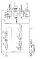
図14は、例えば、服部、田中、浅野、浅井、坂戸:「衛星利用放送品質コーデック」、三菱電機技報、vol.67、No.7、pp33−38(1993)に示されたマルチメディア情報処理装置の構成である。
【0003】
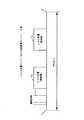
次に、従来のディジタルビデオ受信装置について図13および図14を用いて説明する。図13は2波伝送モードによる衛星トランスポンダ上の信号周波数配列の例である。なお、図中、高画質モードとは、トランスポンダ当り2波伝送とし、より高品質なビデオおよびオーディオを伝送するモードを意味し、SNG(Satellite News Gathering)多重モードとは、通信衛星スーパーバードのトランスポンダで最大4波の伝送が可能なSNGモードを2番組多重化し、1波で2番組のビデオを伝送するモードである。図13では2波が多重されているが、1波ごとに2チャンネルの番組を多重している。
図13で示す2波を分離して同時に受信する場合は、図13の番組受信装置400が4台(2[台]×2[番組])必要になる。高画質モードでは1波1番組であるのでSNG多重モード(1波2番組)の場合で説明するが、図14に示すようにSNG多重モードの信号が2波多重されている場合の復号動作を説明する。
【0004】
図14においてダウンコンバータ402では、受信したIF(中間周波数)信号401の内、図13に示す511または512の何れか1波を選択し、QPSK復調回路403にて選択した1波をディジタル復調し、ビタビ復号器404にて誤り訂正を行ない、2CH分離器410にて1波の信号を2つの番組に分離する。そのうちの一方の番組信号はデインタリーブ部411、リードソロモン復号器412およびデスクランブル部413にて誤り訂正され、多重分離器430へ出力される。
【0005】
もう一方の番組信号は、2CH分離器410よりディジタルビデオ出力422として分離され、もう一台の番組受信装置400のディジタルビデオ入力421として2CH分離器410に入力され前記と同じように411、412、413の回路によって誤り訂正された多重分離器430へ出力される。
【0006】
従来例では、1つのSNG多重波は2つの番組より構成されており、2CH分離器410で1番組ごとに分離された後、多重分離器430でVBI(垂直帰線区間)信号431を入力してビデオ信号441を出力し端末に出力する。またオーディオ復号器433では多重分離器430より入力したオーディオ符号化信号を復号しオーディオ信号422を出力する。同ように、オーダーワイヤインタフェース部434より連絡回線信号443をデータインタフェース部435より端末データ信号等444を出力する。
【0007】
【発明が解決しようとする課題】
従来、ディジタルに符号化された番組しか受信できなかったため、アナログビデオ画像およびディジタルビデオ画像を同一受信端末装置では受信できなかった。
【0008】
また、従来のディジタルビデオ受信端末装置は1つのディジタルビデオ番組を受信できるだけであり、マルチチャンネルのディジタルビデオ画面表示ができなかった。
【0009】
さらに、従来のディジタルビデオ受信端末装置では、複数の端末(モニタ)において独立した異なったディジタルビデオ画像を表示できなかった。
【0010】
従来のディジタルビデオ受信装置端末におけるデータ分離器は、1つの番組のみに付随するデータを分離するのみで、複数のディジタルビデオ番組に対応してデータを出力できなかった。
【0011】
さらに、従来のディジタルビデオ受信装置端末におけるデータ復号器は、例えば、高画質のディジタルTVであるHDTV(High Definition Television)の復号に必要な演算が通常のディジタルTVであるSDTV(Standard Definition Television)に比較して6倍である場合、1つのHDTV画像または1つのSDTV画像の復号は可能であったが、複数のSDTV画像および複数の複数SDTVと1つのHDTV画像の同時復号はできなかった。
【0016】
【課題を解決するための手段】
第1の発明においては、符号化ビデオ信号、符号化オーディオ信号、符号化データ信号の各ビットストリームを多重した多重化信号により、ビデオ、オーディオ、データからなるメディアを含んだ番組の配送を行なうディジタル放送サービスを受信して、番組を受信者に供給するディジタルビデオ受信装置は、多重化信号を受信してディジタルベースバンド信号に変換するチューナと、チューナから供給されたディジタルベースバンド信号を復号する復調器と、復調器から出力された符号化ビデオ信号、符号化オーディオ信号、符号化データ信号が多重された多重化信号から、ビデオ信号のビットストリーム、オーディオ信号のビットストリーム、データ信号のビットストリーム、番組対応のクロックおよび受信したビットストリームを識別するためのストリーム識別信号を分離して出力する多重データ分離器と、ビデオ信号のビットストリームを分割するビットストリーム分割器と複数のビデオ復号ユニットとを備え、多重データ分離器で分離されたビデオ信号を復号するビデオ復号器と、多重データ分離器で分離されたオーディオ信号を復号するオーディオ復号器と、多重データ分離器で分離されたデータ信号を復号するデータ復号器と、ビデオ復号器から出力された複数のビデオ信号を1つの画面上に表示するように信号変換を行う表示変換合成器と、オーディオ復号器から出力されたオーディオ信号を選択するオーディオ選択器と、データ復号器から出力されたデータ信号を選択するデータ選択器とを備え、復調器から出力された多重化信号がSDTVの場合には、多重データ分離器は、外部からの選択指示信号により選択された1以上の番組を構成するビデオ信号のビットストリーム、オーディオ信号のビットストリーム、データ信号のビットストリーム、番組対応のクロックおよびストリーム識別信号を分離して出力し、ビットストリーム分割器は、切換信号に従って多重データ分離器から出力されたビデオ信号から各番組を構成するチャンネル毎に分離されたビデオストリームを生成して出力し、各ビデオ復号ユニットは、各チャネル毎にビデオストリーム信号を復号し各チャンネル毎のビデオ出力信号として出力し、表示変換合成器は、各ビデオ復号器から出力された各チャンネル毎のビデオ出力信号を合成して各チャンネル毎のビデオ出力信号が1つの画面上に表示されるようにし、復調器から出力された多重化信号がHDTVの場合には、多重データ分離器は、複数の部分画像を構成するビデオ信号のストリーム、オーディオ信号のストリーム、データ信号のビットストリーム、部分画像対応のクロックおよびストリーム識別信号を分離して出力し、ビットストリーム分割器は、切換信号に従って多重データ分離器から出力されたビデオ信号から各部分毎に分離されたビデオストリームを生成して出力し、各ビデオ復号ユニットは、各部分毎にビデオストリーム信号を復号し各部分毎のビデオ出力信号として出力し、表示変換合成器は、各ビデオ復号器から出力された各部分毎のビデオ信号を合成して部分画像から1画面の画像が表示されるように構成される。
【0018】
第2の発明においては、表示変換合成器は、複数の拡大・縮小器および画面オーバレイ
ユニットを有し、SDTVの場合にはビデオ復号器から入力した復号信号を1つのモニタで表示できるサイズになるように拡大・縮小器で拡大・縮小し、それらの拡大・縮小された複数の画像信号を画面オーバレイユニットで重ね合わせて1つのモニタ画面上に表示できるビデオ信号を生成するように構成される。
【0019】
第3の発明においては、さらに、NTSC/PALデコーダを備え、チューナは受信信号をPAL/NTSCのアナログベースバンド信号とディジタルベースバンド信号に分岐し、NTSC/PALデコーダはチューナから供給されたアナログベースバンド信号を復号し、復号ビデオ信号を生成し、表示変換合成器はNTSC/PALデコーダからのアナログ画像信号とビデオ復号器からのディジタル画像信号とを合成し、1つのモニタ上にアナログ画像信号とディジタル画像信号とを表示できるビデオ信号を生成するように構成される。
【0020】
第4の発明においては、表示変換合成器は、画面再生器および画面オーバレイユニットを有し、ビデオ復号器からディジタルHDTV画像信号を合成し1つのモニタで表示アされるビデオ信号を生成し、一方、NTSC/PALデコーダからのアナログTV信号が存在するときは、HDTVの画像信号とアナログTV信号を画面オーバレイユニットで重ね合わせて1つのモニタ画面上に表示できるビデオ信号を生成するように構成される。
【0021】
【発明の実施の形態】
実施の形態1.
次に、本発明の実施の形態1のディジタルビデオ受信装置を図1〜図3を用いて説明する。図1は本発明の実施の形態1のディジタルビデオ受信装置の概略構成を示す図である。図1において、111は入力端子、103はチューナ、104は復調器、105は多重データ分離器、106はビデオ復号器、107はオーディオ復号器、108はデータ復号器、149は入力受信信号、150は番組選択指示信号、153はビデオストリーム、154はクロック信号、155はストリーム識別信号、(156a,156b・・・・156n)はビデオ出力信号、(157a,157b・・・・157n)はオーディオ出力信号、(160a,160b・・・・160n)はデータ出力信号、185は多重化信号である。
【0022】
次に、本発明の実施の形態1のディジタルビデオ受信装置の動作について説明する。入力端子111に入力された入力受信信号は、チューナ103で必要な信号成分が取り出され、復調器104で復調され多重化信号185となり、多重データ分離器105に入力する。多重データ分離器105に入力した多重化信号185は、複数の番組が符号化され1つのストリームに多重された多重化信号であり、この多重化信号185は、図12に示すように、複数の番組から構成されたビットストリームで構成される。図12において、多重化信号185は、nチャネルのビデオ信号、nチャネルのオーディオ信号、nチャネルのデータ信号が含まれている。各ビデオ信号、オーディオ信号、データ信号のヘッダには各チャネルに必要な付随データ、たとえば、クロック等が含まれる。
【0023】
多重データ分離器105では、多重化信号185の中から、ビデオ信号、オーディオ信号、データ信号を分離すると共に、外部から入力された番組選択指示信号150により、所望の番組の符号化データのみを取り出す。たとえば、分離されたビデオ信号には、ビデオストリーム153、番組対応のクロック信号154および番組を抽出するための制御信号であるストリーム識別信号155が含まれ、ビデオ復号器106に出力される。また、分離されたオーディオ信号には、オーディオストリーム信号170、番組対応のクロック信号171および番組を抽出するための制御信号であるストリーム識別信号172が含まれ、オーディオ復号器107に出力される。一方、分離されたデータ信号には、分離化データ信号180、番組対応のクロック信号181および番組を抽出するための制御信号であるストリーム識別信号182が含まれ、データ復号器108に出力される。
【0024】
ビデオ復号器106では入力された番組対応のクロック信号154およびストリーム識別信号155を用いて、各ビデオストリームを復号し、各番組毎のビデオ復号信号(156a、156b、・・・・156n)をビデオ出力信号として出力する。
【0025】
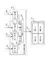
次に、本発明の実施の形態1のディジタルビデオ受信装置におけるビデオ復号器106を図2を用いて説明する。図2において、201は入力ビットストリームを各番組毎に分割するビットストリーム分割器、(202a,202b・・・・202n)は各チャネル毎のビデオ復号ユニット、(203a,203b・・・・203n)は各チャネル毎のビデオ信号を復号するチャネルビデオ復号器、(204a,204b・・・・204n)はビデオ信号を復号化するために使用される各チャネル毎のメモリ、(250a,250b・・・・250n)は各チャネル毎のビデオビットストリームである。
【0026】
次に、ビデオ復号器106の動作について説明する。ビデオ復号器106に入力されたビデオストリーム153はストリーム識別信号155でを用いて番組に対応するチャネル毎のビットストリームに分割され、チャネルa(CHa)のビットストリームはビデオ復号ユニット202aに、チャネルb(CHb)のビットストリームはビデオ復号ユニット202bに、チャネルc(CHc)のビットストリームはビデオ復号ユニット202cにに送られる。
【0027】
各ビデオ復号ユニット(202a,202b・・・・202n)は従来のSDTV(Standard Definition TV)クラスのビデオ復号処理の能力を有する。各ビデオ復号ユニット(202a,202b・・・・202n)では、各チャネルごとに分割された各ビデオストリーム(250a,250b・・・・250n)を復号し、それぞれ各チャネルごとのビデオ出力信号(156a,156b・・・・156n)として出力する。ここで、ビデオ復号の際は、ビデオ復号ユニット(202a,202b・・・・202n)は、供給されたビデオクロック154をマスタのクロックとしてビデオ復号を行なう。各ビデオ復号ユニット(202a,202b・・・・202n)は、内部の各チャネルビデオ復号器(2032a,203b・・・・203n)およびメモリ204を使用してビデオ信号を復号し、各ビデオ出力信号(156a,156b・・・・156n)を出力する。
【0028】
オーディオ復号器107においては、入力されたオーディオストリーム170を復号し、各番組毎のオーディオ復号信号(157a、157b、・・・・157n)をオーディオ出力信号として出力する。また、データ復号器108においても同様に、入力されたデータストリーム180を復号し、各番組毎のデータ復号信号(160a、160b、・・・・160n)をデータ出力信号として出力する。
【0029】
図3は本発明の実施の形態1のディジタルビデオ受信装置に複数のモニタ(332a、332b、・・・・332n)を接続した状態を示す図である。図3において、(330a、330b、・・・・330n)はビデオ出力端子を示す。ビデオ出力端子330aは図1に示すビデオ出力信号156a,オーディオ出力信号157a,データ出力信号160aを含み、ビデオ出力端子330bは図1に示すビデオ出力信号156b,オーディオ出力信号157b,データ出力信号160bを含み、ビデオ出力端子330nは図1に示すビデオ出力信号156n,オーディオ出力信号157n,データ出力信号160nを含む信号である。このようにビデオ復号器106、オーディオ復号器107およびデータ復号器108からの出力信号はそれぞれ組になってそれぞれのモニタに出力され、各モニタにおいてビデオ、オーディオおよびデータを再現することができる。
【0030】
ビデオ復号器106およびオーディオ復号器107およびデータ復号器108から出力されたビデオ復号信号(156a,156b・・・・156n)、オーディオ復号信号(157a,157b・・・・157n)、データ復号化信号(160a,160b・・・・160n)は、独立の信号として本発明のディジタルビデオ受信端末から出力されるので、ディジタルビデオ受信装置の端子にそれぞれ異なるモニタを接続することにより別々のモニタで異なる映像を見ることができる。
【0031】
実施の形態2.
次に、本発明の実施の形態2のディジタルビデオ受信装置を図4を用いて説明する。図4は、本発明の実施の形態2のディジタルビデオ受信装置の概略構成示す図である。実施の形態2においては、多重データ分離器で分離された多重化ビデオストリームはさらにチャネル分離器で各チャネル毎に分離されたビデオ復号器に供給される。図4において、111は入力端子、103はチューナ、104は復調器、105は多重データ分離器、106はビデオ復号器、107はオーディオ復号器、108はデータ復号器、115はチャネル分離器、153a〜153nは多重化ビデオストリーム、154はクロック信号、(156a,156b・・・・156n)はビデオ出力信号、157はオーディオ出力信号、160データ出力信号、(170a,170b・・・・170n)はオーディオストリーム、(180a,180b・・・・180n)は多重化データ信号、185は多重化信号である。
【0032】
次に、本発明の実施の形態2のディジタルビデオ受信装置の動作について説明する。入力端子111に入力された多重化ディジタル信号は、ディジタルビデオ受信装置の入力端子111に入力し、チューナ103で取り出され、復調器104で復調され多重化信号となり、多重データ分離器105に入力する。多重データ分離器105に入力した多重化信号185は、実施の形態1に示すストリーム構成と同じである。
【0033】
多重データ分離器105では、多重化信号185からビデオストリーム、クロック信号およびチャネルを分離するためのストリーム識別信号を生成し、チャネル分離器115において、多重データ分離器105で生成されたストリーム識別信号155を用いて各チャネル毎に分離されたチャネル分離ビデオストリーム(153a、153b、・・・・153n)および各チャネル毎に分離されたチャネル分離クロック信号(154a、154n、・・・・154n)を生成する。ビデオ復号器106では入力された番組対応のチャネル分離ビデオストリーム(153a、153b、・・・・153n)をチャネル分離クロック信号(154a、154n、・・・・154n)を用いて復号し、各番組毎のビデオ復号信号(156a、156b、・・・・156n)をビデオ出力信号として出力する。
【0034】
オーディオ復号器107においては、入力された番組対応の各オーディオストリーム(170a,170b・・・・170n)を復号し、各番組毎のオーディオ復号信号(157a、157b、・・・・157n)をオーディオ出力信号として出力する。また、データ復号器108においても同様に、入力された番組対応の各データストリーム(180a,180b・・・・180n)を復号し、各番組毎のデータ復号信号(160a、160b、・・・・160n)をデータ出力信号として出力する。
【0035】
ビデオ復号器106の各番組毎のビデオ復号信号(156a、156b、・・・・156n)、オーディオ復号信号(157a、157b、・・・・157n)およびデータ復号信号(160a、160b、・・・・160n)は図3に示す実施の形態1の場合と同様にn台のモニタに接続される。
【0036】
ビデオ復号器106およびオーディオ復号器107およびデータ復号器108から出力されたビデオ復号信号(156a,156b・・・・156n)、オーディオ復号信号157、データ復号信号(160a,160b・・・・160n)は、独立の信号として本発明のディジタルビデオ受信端末から出力されるので、ディジタルビデオ受信装置の端子にそれぞれ異なるモニタを接続することにより別々のモニタで異なる映像を見ることができる。
【0037】
次に、本発明の実施の形態2のディジタルビデオ受信装置におけるビデオ復号器106を図5を用いて説明する。図5においては、ビデオ復号器106への入力信号はnCHのビデオ信号が多重化された多重化ビデオ信号ではく、各チャネル毎にすでに分離されたビデオ信号である点が実施の形態1のビデオ復号器106と異なる。図5において、(202a,202b・・・・202n)はビデオ復号ユニット、(203a,203b・・・・203n)はチャネル毎のビデオ復号器、(204a,204b・・・・204n)はメモリである。
【0038】
ビデオ復号器106のビデオチャネルaを復号するビデオ復号器106aに入力されたビデオストリーム153a、クロック信号154a、ストリーム識別信号155aは、ビデオ復号ユニット202aに送られる。ビデオ復号ユニット202aにおける動作は図2に示す実施の形態1の場合と同じであるので詳細な説明は省略する。ビデオ復号器106の他のチャネルについても同様にして、ビデオ復号信号(156b,・・・・156n)を出力する。これらのビデオ復号信号(156a,156b・・・・156n)にモニタを接続することによって各チャネル毎に異なるビデオ画像が再現される。
【0039】
実施の形態3.
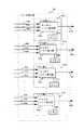
次に、本発明の実施の形態3のディジタルビデオ受信装置を図6を用いて説明する。図6は、本発明の実施の形態3のディジタルビデオ受信装置の概略構成示す図である。図6において、111は入力端子、103はチューナ、104は復調器、105は多重データ分離器、106はビデオ復号器、107はオーディオ復号器、108はデータ復号器、109は表示変換合成器、110はオーディオ選択器、115はデータ選択器、148は選択指示信号、153はビデオストリーム、154はクロック信号、155はストリーム識別信号、(156a,156b・・・・156n)はビデオ復号化信号、(157a,157b・・・・157n)はオーディオ復号化信号、158はビデオ出力信号、159はオーディオ出力信号、(160a,160b・・・・160n)はデータ復号化信号、161はデータ出力信号、185は多重化信号である。
【0040】
次に、本発明の実施の形態3のディジタルビデオ受信装置の動作について説明する。入力端子111に入力された多重化ディジタル信号は、チューナ103で所望の信号成分が取り出され、復調器104で復調され多重化信号185となり、多重データ分離器105に入力する。実施の形態3のディジタルビデオ受信装置が実施の形態1および2のディジタルビデオ受信装置と異なる点は、後者では通常のSDTV信号が入力端子111に入力するのに対して、本発明の実施の形態においては、入力端子111に入力する信号はSDTV信号および/またはHDTVである点にある。SDTVにおいては、ビデオ復号器106の処理までは、実施の形態1で述べたディジタルビデオ受信装置と同様であるが、HDTVについては、その信号の帯域幅が広く、各ビデオ復号器106は全てのHDTV信号を一度で復号する事はできない。従って、HDTV信号を複数の画面に対応する部分信号に分割し、分割された各々の部分信号を各ビデオ復号器106で復号し、その後復号された信号を合成することによってHDTVを再生する。
【0041】
次に、図7を参照してSDTVおよび/またはHDTVがビデオ復号器106に入力した場合のビデオ復号器106の動作について説明する。ビットストリーム分割器201は入力したビットストリーム153がHDTV(High Definition TV)か従来のSDTV(Standard Definition TV)かによって、切換信号205は分割方式を切り替える。この切換信号205はビデオストリーム153の種類に従ってビットストリーム分割器201の内部で生成してもよい。
【0042】
まず、ビデオ復号器106に入力した信号がSDTVの場合について説明する。ビットストリーム分割器201では、ビデオ復号器106に入力されたビデオストリーム153、クロック信号154、ストリーム識別信号155は各チャネル毎に分割され、各ビデオ復号ユニット(202a,202b・・・・202n)に送られる。この場合は、ビデオ復号器106からビデオ復号信号(156a,156b・・・・156n)が出力されるが、その生成方法は実施の形態1と同様であるので、説明を省略する。
【0043】
次に、ビデオ復号器106に入力した信号がHDTVの場合について説明する。ビデオ復号器106に入力したHDTV信号は、ビデオ復号器106に入力されたビデオストリーム153、クロック信号154、ストリーム識別信号155に基づいて、各部分画面に対応する部分ビデオ信号毎に分割され、各ビデオ復号ユニット(202a,202b・・・・202n)に送られる。各ビデオ復号ユニット(202a,202b・・・・202n)は、部分ビデオ復号器(2032a,203b・・・・203n)で各部分ビデオ信号を復号し、場合によって隣接する各ビデオ復号ユニット(202a,202b・・・・202n)からデータが必要な場合は、ビデオ復号ユニット間接続線(255a,255b・・・・255n)およびメモリ(204a,204b・・・・204n)を使用しながら復号処理を行い、部分ビデオ復号信号(156a,156b・・・・156n)を出力する。
【0044】
次に、ビデオ復号器106から出力されたビデオ復号信号(156a,156b・・・・156n)は、表示変換合成器109に入力される。表示変換合成器109においては、ビデオ出力信号(156a,156b・・・・156n)が合成されて、1つのモニタに複数の分割画面を表示する。その例を図8および図9に示す。
【0045】
図8は、複数のSDTV復号信号が1つのモニタに表示される例を示す図である。図8において、109は表示変換合成器109、(310a,310b・・・・310n)は拡大・縮小器、302は画面オーバレイユニット、(332a、332b、・・・・332n)はモニタである。図8において、表示変換合成器109に入力されたビデオ復号信号(156a,156b・・・・156n)は各チャネル毎に拡大・縮小器(310a,310b・・・・310n)に入力され、そこでモニタとの関係で所望のサイズで拡大・縮小され、画面オーバレイユニット302で合成され、合成信号352としてモニタ332に出力され、モニタ332の1画面上に複数のチャネルが画像表示される。
【0046】
図9は、複数の部分ビデオ信号に分割してそれぞれ復号されたHDTV画像を1つのモニタに表示する例を示す図である。図9において、109は表示変換合成器109、(310a,310b・・・・310n)は拡大・縮小器、302は画面オーバレイユニット、332はモニタである。図9において、表示変換合成器109に入力された部分ビデオ復号信号(156a,156b・・・・156n)は各部分毎に拡大・縮小器(310a,310b・・・・310n)に入力され、そこでモニタとの位置関係で所望のサイズに拡大・縮小され、画面オーバレイユニット302で合成され、合成信号352としてモニタ332に出力され、モニタ332上で一つのHDTV画像が表示される。
【0047】
なお、オーディオ復号器107においては、入力された複数のオーディオストリーム170を復号し、オーディオ選択器110に送出し、オーディオ選択指示信号によって所望のオーディオ信号が選択されて(この場合はたとえば、157aのみが選択されて)オーディオ出力信号159として出力される。また、データ復号器108においても同様に、データストリーム180を復号し、所望のデータ復号信号160aをが選択されたデータ出力信号として出力される。
【0048】
実施の形態4.
以下、本発明における実施の形態4のディジタルビデオ受信装置を図10、図11を用いて説明する。図10は、本発明の実施の形態4のディジタルビデオ受信装置の概略構成を示す図である。図10において、101はチューナ、102はNTSC/PALデコーダ、104は復調器、105は多重データ分離器、106はビデオ復号器、107はオーディオ復号器、108はデータ復号器、109は表示変換合成器、110はオーディオ選択器、115はデータ選択器、148は選択指示信号、149はディジタルベースバンド信号、151はアナログベースバンド信号、152はアナログビデオ信号、153はビデオストリーム、154はクロック信号、155はストリーム識別信号、(156a,156b・・・・156n)はビデオ復号信号、(157a,157b・・・・157n)はオーディオ復号信号、158はビデオ出力信号、159はオーディオ出力信号、(160a,160b・・・・160n)はデータ復号化信号、161はデータ出力信号、185は多重化信号である。
【0049】
次に、図10に示される本発明の実施の形態4のディジタルビデオ受信装置の動作について説明する。衛星通信または地上波通信を介して受信された受信信号はチューナ101によりアナログベースバンド信号151とディジタルベースバンド信号149に分岐され、アナログベースバンド信号151はNTSC/PALデコーダ102でアナログビデオ信号152になり、ディジタルベースバンド画像信号149は、復調器104で復調され、多重データ分離器105に入力される。多重データ分離器105に入力される多重化信号185は、複数の番組を符号化して1つのストリームに多重されたSDTV信号または一つのHDTVを運ぶ信号1である。図12に、SDTVにおける複数の番組から構成されたビットストリームを示す。
【0050】
多重データ分離器105は、入力された多重化信号185をビデオ信号、オーディオ信号およびデータ信号に分離し、さらに各信号は、ストリーム信号、クロック信号およびストリーム識別信号に分離して出力する。たとえば、SDTVの場合には、ビデオ信号に対しては、多重データ分離器105は、ビデオストリーム153、番組対応のクロック信号154および番組を選択するための制御信号であるストリーム識別信号155をビデオ復号器106に出力する。オーディオ信号に対しては、多重データ分離器105は、オーディオストリーム信号170、番組対応のクロック信号171および番組を選択するための制御信号であるストリーム識別信号172をオーディオ復号器107に出力する。データ信号についても同様である。HDTVの場合には、多重化信号185の中から部分信号ストリーム154、部分信号対応のクロック信号154および部分信号を選択するための制御信号であるストリーム識別信号155をビデオ復号器106に出力する。なお、SDTVの場合には、外部から入力された選択指示信号148により、必要な番組のみを抽出してビデオストリーム153として出力する。
【0051】
ビデオ復号器106においては、SDTVに場合には、各番組に対応したビデオ出力信号(156a,156b・・・・156n)が出力され、HDTVの場合には、各部分毎のビデオ復号信号(156a、156b、・・・・156n)が出力される。ビデオ復号器106における復号方法は、実施の形態3と同様であるので、説明を省略する。
【0052】
実施の形態4における表示変換合成器109は、ビデオ復号器106から出力されたHDTVビデオ復号信号(156a,156b・・・・156n)を合成すると共に、NTSC/PALデコーダ102から出力されたアナログビデオ152がある場合はその画像をも1つの画面上に合成して、ビデオ信号158として出力する。画面合成の方法の1例を図11に示す。
【0053】
図11は、1つのHDTV画像と1つのSDTV画像を同時に復号しメッセージ上で同一画面に表示する1例を示す。図11において、ビデオ復号器106から出力されたHDTVビデオ復号信号(156a,156b・・・・156n)は、画面再生器301で複数の部分ビデオ信号を合成し、HDTVの画像に再生を行ない、さらにアナログ映像とピクチャインピクチャを行なう場合には、画面オーバレイユニット302でオーバレイ処理を行ないアナログ画面とディジタルHDTV画面とを1つの画面としてビデオ信号158を出力する。信号はモニタ332でアナログ画像とHDTV画像とを1つの画面にピクチャインピクチャの形式で表示させることができる。なお、多重化信号185がSDTVの場合には、実施の形態3で述べたように、画面再生器301で複数のSDTVビデオ信号を合成し、その後に画面オーバレイユニット302で複数のSDTV画像とアナログ画像とを、一つのモニタ画面上に表示することもできる。
【0058】
【発明の効果】
第1の発明においては、符号化ビデオ信号、符号化オーディオ信号、符号化データ信号の各ビットストリームを多重した多重化信号により、ビデオ、オーディオ、データからなるメディアを含んだ番組の配送を行なうディジタル放送サービスを受信して、番組を受信者に供給するディジタルビデオ受信装置は、多重化信号を受信してディジタルベースバンド信号に変換するチューナと、チューナから供給されたディジタルベースバンド信号を復号する復調器と、復調器から出力された符号化ビデオ信号、符号化オーディオ信号、符号化データ信号が多重された多重化信号から、ビデオ信号のビットストリーム、オーディオ信号のビットストリーム、データ信号のビットストリーム、番組対応のクロックおよび受信したビットストリームを識別するためのストリーム識別信号を分離して出力する多重データ分離器と、ビデオ信号のビットストリームを分割するビットストリーム分割器と複数のビデオ復号ユニットとを備え、多重データ分離器で分離されたビデオ信号を復号するビデオ復号器と、多重データ分離器で分離されたオーディオ信号を復号するオーディオ復号器と、多重データ分離器で分離されたデータ信号を復号するデータ復号器と、ビデオ復号器から出力された複数のビデオ信号を1つの画面上に表示するように信号変換を行う表示変換合成器と、オーディオ復号器から出力されたオーディオ信号を選択するオーディオ選択器と、データ復号器から出力されたデータ信号を選択するデータ選択器とを備え、復調器から出力された多重化信号がSDTVの場合には、多重データ分離器は、外部からの選択指示信号により選択された1以上の番組を構成するビデオ信号のビットストリーム、オーディオ信号のビットストリーム、データ信号のビットストリーム、番組対応のクロックおよびストリーム識別信号を分離して出力し、ビットストリーム分割器は、切換信号に従って多重データ分離器から出力されたビデオ信号から各番組を構成するチャンネル毎に分離されたビデオストリームを生成して出力し、各ビデオ復号ユニットは、各チャネル毎にビデオストリーム信号を復号し各チャンネル毎のビデオ出力信号として出力し、表示変換合成器は、各ビデオ復号器から出力された各チャンネル毎のビデオ出力信号を合成して各チャンネル毎のビデオ出力信号が1つの画面上に表示されるようにし、復調器から出力された多重化信号がHDTVの場合には、多重データ分離器は、複数の部分画像を構成するビデオ信号のストリーム、オーディオ信号のストリーム、データ信号のビットストリーム、部分画像対応のクロックおよびストリーム識別信号を分離して出力し、ビットストリーム分割器は、切換信号に従って多重データ分離器から出力されたビデオ信号から各部分毎に分離されたビデオストリームを生成して出力し、各ビデオ復号ユニットは、各部分毎にビデオストリーム信号を復号し各部分毎のビデオ出力信号として出力し、表示変換合成器は、各ビデオ復号器から出力された各部分毎のビデオ信号を合成して部分画像から1画面の画像が表示されるように構成されるので、1つのディジタルビデオ受信端末で1つのHDTV解像度の画像を見ることができると共に、複数のSDTV解像度の番組を同時に見ることが可能になる。
【0060】
第2の発明においては、表示変換合成器は、複数の拡大・縮小器および画面オーバレイユニットを有し、SDTVの場合にはビデオ復号器から入力した復号信号を1つのモニタで表示できるサイズになるように拡大・縮小器で拡大・縮小し、それらの拡大・縮小された複数の画像信号を画面オーバレイユニットで重ね合わせて1つのモニタ画面上に表示できるビデオ信号を生成するように構成されるので、1つのディジタルビデオ受信端末で1つのHDTV解像度の画像を見ることができと共に、複数のSDTV解像度の番組を同時に見ることが可能になる。
【0061】
第3の発明においては、さらに、NTSC/PALデコーダを備え、チューナは受信信号をNTSC/PALのアナログベースバンド信号とディジタルベースバンド信号に分岐し、NTSC/PALデコーダはチューナから供給されたアナログベースバンド信号を復号し、復号ビデオ信号を生成し、表示変換合成器はNTSC/PALデコーダからのアナログ画像信号とビデオ復号器からのディジタル画像信号とを合成し、1つのモニタ上にアナログ画像信号とディジタル画像信号とを表示できるビデオ信号を生成するように構成されるので、ディジタルで送信されてきたディジタル番組およびアナログで送信されてきたアナログ番組を同時にデコードし、同じモニタ上に表示することが可能になる。
【0062】
第4の発明においては、表示変換合成器は、画面再生器および画面オーバレイユニットを有し、ビデオ復号器からディジタルHDTV画像信号を合成し1つのモニタで表示アされるビデオ信号を生成し、一方、NTSC/PALデコーダからのアナログTV信号が存在するときは、HDTVの画像信号とアナログTV信号を画面オーバレイユニットで重ね合わせて1つのモニタ画面上に表示できるビデオ信号を生成するように構成されるので、ディジタルで送信されてきたディジタル番組およびアナログで送信されてきたアナログ番組を同時にデコードし、同じモニタ上に表示することが可能になる。
【図面の簡単な説明】
【図1】 実施の形態1のディジタルビデオ受信装置の構成を示す図である。
【図2】 実施の形態1のディジタルビデオ受信装置に用いるビデオ復号器を示す図である。
【図3】 実施の形態1のディジタルビデオ受信装置に複数のモニタを接続した状態を示す図である。
【図4】 実施の形態2のディジタルビデオ受信装置の構成を示す図である。
【図5】 実施の形態2のディジタルビデオ受信装置におけるビデオ復号器を示す図である。
【図6】 実施の形態3のディジタルビデオ受信装置の構成を示す図である。
【図7】 実施の形態3のディジタルビデオ受信装置に用いるビデオ復号器を示す図である。
【図8】 実施の形態3のディジタルビデオ受信装置における複数のSDTV信号を1つのモニタに表示する例を示す図である。
【図9】 実施の形態3のディジタルビデオ受信装置におけるHDTV画像を1つのモニタに表示する例を示す図である。
【図10】 実施の形態4のディジタルビデオ受信装置の構成を示す図である。
【図11】 実施の形態4のディジタルビデオ受信装置における1つのSDTV画像と1つのHDTV画像を1つのモニタに表示する例を示す図である。
【図12】 本発明の実施の形態における多重化信号の構成例を示す図である。
【図13】 従来技術ににおける衛星トランスポンダ上の信号周波数配列の一例を示す図である。
【図14】 従来技術ににおけるディジタルビデオ受信端末装置の一例を示す図である。
【符号の説明】
102 NTSC/PALデコーダ、 103 チューナ、 104 復調器、 105 多重データ分離器、 106 ビデオ復号器、 107 オーディオ復号器、 108 データ復号器、 109 表示変換合成器、 110 オーディオ選択器、 201 ビットストリーム分割器、 202 ビデオ復号ユニット、 203 チャネルビデオ復号器または部分ビデオ復号器、 204 メモリ、 255 ビデオ復号ユニット間接続線、 302 画面オーバレイユニット、 310 拡大・縮小器、 332 モニタ[0001]
BACKGROUND OF THE INVENTION
The present invention relates to a receiver for receiving digital video from a digital TV, a digital CATV or a digital broadcasting system.
[0002]
[Prior art]
FIG. 14 shows, for example, Hattori, Tanaka, Asano, Asai, Sakado: “Broadcast quality codec using satellite”, Mitsubishi Electric Technical Report, vol. 67, no. 7, pp 33-38 (1993).
[0003]
Next, a conventional digital video receiving apparatus will be described with reference to FIGS. FIG. 13 shows an example of signal frequency arrangement on the satellite transponder in the two-wave transmission mode. In the figure, the high image quality mode means a mode in which two waves are transmitted per transponder and transmits higher quality video and audio, and the SNG (Satellite News Gathering) multiplexing mode means a transponder of a communication satellite superbird. In this mode, two programs of SNG mode capable of transmitting a maximum of four waves are multiplexed, and video of two programs is transmitted by one wave. In FIG. 13, two waves are multiplexed, but two channels of programs are multiplexed for each wave.
When two waves shown in FIG. 13 are separated and received simultaneously, four program receiving apparatuses 400 (2 [units] × 2 [programs]) in FIG. 13 are required. In the high image quality mode, since one program is one wave, a description will be given in the case of the SNG multiplex mode (one wave, two programs). However, as shown in FIG. explain.
[0004]
In FIG. 14, the
[0005]
The other program signal is separated from the
[0006]
In the conventional example, one SNG multiplexed wave is composed of two programs. After being separated for each program by the
[0007]
[Problems to be solved by the invention]
Conventionally, since only digitally encoded programs can be received, analog video images and digital video images cannot be received by the same receiving terminal device.
[0008]
Also, the conventional digital video receiving terminal device can only receive one digital video program and cannot display a multi-channel digital video screen.
[0009]
Further, the conventional digital video receiving terminal device cannot display different digital video images independently on a plurality of terminals (monitors).
[0010]
A conventional data separator in a digital video receiver terminal only separates data associated with only one program and cannot output data corresponding to a plurality of digital video programs.
[0011]
Further, the data decoder in the conventional digital video receiver terminal is, for example, an SDTV (Standard Definition Television), which is a normal digital TV, which performs operations necessary for decoding HDTV (High Definition Television) which is a high-quality digital TV. When the comparison is 6 times, one HDTV image or one SDTV image can be decoded, but a plurality of SDTV images and a plurality of SDTV images and one HDTV image cannot be decoded simultaneously.
[0016]
[Means for Solving the Problems]
First1 In the invention ofBy a multiplexed signal obtained by multiplexing each bit stream of an encoded video signal, an encoded audio signal, and an encoded data signal, Video, audio, dataConsist of Programs that include mediaof A digital video receiving apparatus that receives a digital broadcasting service for delivery and supplies a program to a receiver includes a tuner that receives a multiplexed signal and converts it into a digital baseband signal, and a digital baseband signal supplied from the tuner And a multiplexed signal obtained by multiplexing the encoded video signal, encoded audio signal, and encoded data signal output from the demodulatorFrom Video signalBitstream Audio signalBitstream , Data signal bitstreams, program clocks andTo identify the received bitstream Separate and output stream identification signalDo Multiple data separators;A bit stream divider for dividing a bit stream of a video signal and a plurality of video decoding units; A video decoder for decoding the video signal separated by the multiple data separator;Separator An audio decoder that decodes the audio signal separated in
[0018]
First2 In this invention, the display conversion synthesizer includes a plurality of enlargement / reduction units and a screen overlay.
In the case of SDTV, a decoded signal input from a video decoder is enlarged / reduced by an enlarger / reducer so that it can be displayed on a single monitor, and a plurality of enlarged / reduced images are obtained. The signals are superimposed on a screen overlay unit and configured to generate a video signal that can be displayed on a single monitor screen.
[0019]
First3 The invention further includes an NTSC / PAL decoder, and the tuner isReceived signal of PAL / NTSC Branching into an analog baseband signal and a digital baseband signal, the NTSC / PAL decoder decodes the analog baseband signal supplied from the tuner to generate a decoded video signal, and the display conversion synthesizer outputs the analog baseband signal from the NTSC / PAL decoder. The image signal and the digital image signal from the video decoder are combined to generate a video signal capable of displaying the analog image signal and the digital image signal on one monitor.
[0020]
First4 In the present invention, the display conversion synthesizer has a screen regenerator and a screen overlay unit, synthesizes a digital HDTV image signal from a video decoder and generates a video signal to be displayed on one monitor, while NTSC When there is an analog TV signal from the / PAL decoder, the HDTV image signal and the analog TV signal are overlapped by a screen overlay unit to generate a video signal that can be displayed on one monitor screen.
[0021]
DETAILED DESCRIPTION OF THE INVENTION
Next, the digital video receiving apparatus according to the first embodiment of the present invention will be described with reference to FIGS. FIG. 1 is a diagram showing a schematic configuration of a digital video receiving apparatus according to
[0022]
Next, the operation of the digital video receiving apparatus according to the first embodiment of the present invention will be described. A necessary signal component is extracted from the input received signal input to the
[0023]
The multiplexed
[0024]
The
[0025]
Next, the
[0026]
Next, the operation of the
[0027]
Each of the video decoding units (202a, 202b,... 202n) has a video decoding processing capability of a conventional SDTV (Standard Definition TV) class. Each video decoding unit (202a, 202b,... 202n) decodes each video stream (250a, 250b,... 250n) divided for each channel, and each video output signal (156a) for each channel. , 156b... 156n). Here, at the time of video decoding, the video decoding units (202a, 202b,... 202n) perform video decoding using the supplied
[0028]
The
[0029]
FIG. 3 is a diagram showing a state where a plurality of monitors (332a, 332b,... 332n) are connected to the digital video receiving apparatus according to the first embodiment of the present invention. In FIG. 3, (330a, 330b,... 330n) indicate video output terminals. The
[0030]
Video decoded signals (156a, 156b,... 156n), audio decoded signals (157a, 157b,... 157n), and data decoded signals output from the
[0031]
Embodiment 2. FIG.
Next, a digital video receiving apparatus according to Embodiment 2 of the present invention will be described with reference to FIG. FIG. 4 is a diagram showing a schematic configuration of the digital video receiving apparatus according to the second embodiment of the present invention. In the second embodiment, the multiplexed video stream separated by the multiplexed data separator is further supplied to the video decoder separated for each channel by the channel separator. In FIG. 4, 111 is an input terminal, 103 is a tuner, 104 is a demodulator, 105 is a multiplex data separator, 106 is a video decoder, 107 is an audio decoder, 108 is a data decoder, 115 is a channel separator, and 153a. ˜153n is a multiplexed video stream, 154 is a clock signal, (156a, 156b... 156n) is a video output signal, 157 is an audio output signal, 160 data output signals, (170a, 170b... 170n) An audio stream (180a, 180b... 180n) is a multiplexed data signal, and 185 is a multiplexed signal.
[0032]
Next, the operation of the digital video receiving apparatus according to the second embodiment of the present invention will be described. The multiplexed digital signal inputted to the
[0033]
The multiplexed
[0034]
The
[0035]
.. 156n), audio decoded signals (157a, 157b,... 157n) and data decoded signals (160a, 160b,... 156n) for each program of the
[0036]
Video decoded signals (156a, 156b,... 156n), audio decoded signals 157, and data decoded signals (160a, 160b,... 160n) output from the
[0037]
Next, the
[0038]
The
[0039]
Embodiment 3 FIG.
Next, a digital video receiving apparatus according to Embodiment 3 of the present invention will be described with reference to FIG. FIG. 6 is a diagram showing a schematic configuration of the digital video receiving apparatus according to the third embodiment of the present invention. In FIG. 6, 111 is an input terminal, 103 is a tuner, 104 is a demodulator, 105 is a multiplex data separator, 106 is a video decoder, 107 is an audio decoder, 108 is a data decoder, 109 is a display conversion synthesizer, 110 is an audio selector, 115 is a data selector, 148 is a selection instruction signal, 153 is a video stream, 154 is a clock signal, 155 is a stream identification signal, (156a, 156b... 156n) is a video decoded signal, (157a, 157b... 157n) is an audio decoded signal, 158 is a video output signal, 159 is an audio output signal, (160a, 160b... 160n) is a data decoded signal, 161 is a data output signal,
[0040]
Next, the operation of the digital video receiving apparatus according to the third embodiment of the present invention will be described. From the multiplexed digital signal input to the
[0041]
next,Refer to FIG. An operation of the
[0042]
First, the case where the signal input to the
[0043]
Next, the case where the signal input to the
[0044]
Next, the video decoded signals (156a, 156b,... 156n) output from the
[0045]
FIG. 8 is a diagram illustrating an example in which a plurality of SDTV decoded signals are displayed on one monitor. In FIG. 8, 109 is a
[0046]
FIG. 9 is a diagram illustrating an example in which an HDTV image that is divided into a plurality of partial video signals and decoded is displayed on one monitor. In FIG. 9, 109 is a
[0047]
The
[0048]
Embodiment 4 FIG.
The digital video receiving apparatus according to the fourth embodiment of the present invention will be described below with reference to FIGS. FIG. 10 is a diagram showing a schematic configuration of a digital video receiving apparatus according to Embodiment 4 of the present invention. In FIG. 10, 101 is a tuner, 102 is an NTSC / PAL decoder, 104 is a demodulator, 105 is a multiplex data separator, 106 is a video decoder, 107 is an audio decoder, 108 is a data decoder, and 109 is display conversion synthesis. 110, an audio selector, 115, a data selector, 148, a selection instruction signal, 149, a digital baseband signal, 151, an analog baseband signal, 152, an analog video signal, 153, a video stream, 154, a clock signal, 155 is a stream identification signal, (156a, 156b... 156n) is a video decoded signal, (157a, 157b... 157n) is an audio decoded signal, 158 is a video output signal, 159 is an audio output signal, (160a , 160b... 160n) are data decoding Signal, the
[0049]
Next, the operation of the digital video receiving apparatus according to the fourth embodiment of the present invention shown in FIG. 10 will be described. The received signal received via satellite communication or terrestrial communication is a tuner.101 Is branched into an analog baseband signal 151 and a
[0050]
The multiplexed
[0051]
In the case of SDTV, the
[0052]
The
[0053]
FIG. 11 shows an example in which one HDTV image and one SDTV image are simultaneously decoded and displayed on the same screen on a message. In FIG. 11, the HDTV video decoded signals (156a, 156b,... 156n) output from the
[0058]
【The invention's effect】
First1 In the invention ofBy a multiplexed signal obtained by multiplexing each bit stream of an encoded video signal, an encoded audio signal, and an encoded data signal, Video, audio, dataConsist of Programs that include mediaof A digital video receiving apparatus that receives a digital broadcasting service for delivery and supplies a program to a receiver includes a tuner that receives a multiplexed signal and converts it into a digital baseband signal, and a digital baseband signal supplied from the tuner And a multiplexed signal obtained by multiplexing the encoded video signal, encoded audio signal, and encoded data signal output from the demodulatorFrom Video signalBitstream Audio signalBitstream , Data signal bitstreams, program clocks andTo identify the received bitstream Separate and output stream identification signalDo Multiple data separators;A bit stream divider for dividing a bit stream of a video signal and a plurality of video decoding units; A video decoder for decoding the video signal separated by the multiple data separator;Separator An audio decoder that decodes the audio signal separated in
[0060]
First2 In the present invention, the display conversion synthesizer has a plurality of enlargement / reduction units and a screen overlay unit. In the case of SDTV, the display conversion synthesizer is sized so that the decoded signal input from the video decoder can be displayed on one monitor. Since it is configured to generate a video signal that is enlarged / reduced by an enlarger / reducer, and a plurality of the enlarged / reduced image signals are superimposed on a screen overlay unit and can be displayed on one monitor screen, One digital video receiving terminal can view one HDTV resolution image, and can simultaneously view a plurality of SDTV resolution programs.
[0061]
First3 The invention further includes an NTSC / PAL decoder, and the tuner isReceive signal is NTSC / PAL Branching into an analog baseband signal and a digital baseband signal, the NTSC / PAL decoder decodes the analog baseband signal supplied from the tuner to generate a decoded video signal, and the display conversion synthesizer outputs the analog baseband signal from the NTSC / PAL decoder. Since the image signal and the digital image signal from the video decoder are combined to generate a video signal capable of displaying the analog image signal and the digital image signal on one monitor, it has been transmitted digitally A digital program and an analog program transmitted in analog can be decoded simultaneously and displayed on the same monitor.
[0062]
First4 In the present invention, the display conversion synthesizer has a screen regenerator and a screen overlay unit, synthesizes a digital HDTV image signal from a video decoder and generates a video signal to be displayed on one monitor, while NTSC When there is an analog TV signal from the / PAL decoder, it is configured to generate a video signal that can be displayed on one monitor screen by superimposing the HDTV image signal and the analog TV signal on the screen overlay unit. It is possible to simultaneously decode a digital program transmitted in digital and an analog program transmitted in analog and display them on the same monitor.
[Brief description of the drawings]
FIG. 1 is a diagram illustrating a configuration of a digital video receiving apparatus according to a first embodiment.
FIG. 2 is a diagram illustrating a video decoder used in the digital video receiving apparatus according to the first embodiment.
FIG. 3 is a diagram illustrating a state in which a plurality of monitors are connected to the digital video receiving apparatus according to the first embodiment.
FIG. 4 is a diagram showing a configuration of a digital video receiving apparatus according to a second embodiment.
FIG. 5 is a diagram illustrating a video decoder in the digital video receiving apparatus according to the second embodiment.
6 is a diagram showing a configuration of a digital video receiving apparatus according to Embodiment 3. FIG.
7 is a diagram showing a video decoder used in the digital video receiving apparatus according to Embodiment 3. FIG.
8 is a diagram showing an example in which a plurality of SDTV signals are displayed on one monitor in the digital video receiving apparatus of Embodiment 3. FIG.
FIG. 9 is a diagram illustrating an example in which an HDTV image is displayed on one monitor in the digital video receiving device according to the third embodiment.
FIG. 10 is a diagram illustrating a configuration of a digital video receiving apparatus according to a fourth embodiment.
FIG. 11 is a diagram illustrating an example in which one SDTV image and one HDTV image are displayed on one monitor in the digital video receiving device according to the fourth embodiment.
FIG. 12 is a diagram showing a configuration example of a multiplexed signal in the embodiment of the present invention.
FIG. 13 is a diagram showing an example of signal frequency arrangement on a satellite transponder in the prior art.
FIG. 14 is a diagram showing an example of a digital video receiving terminal device in the prior art.
[Explanation of symbols]
102 NTSC / PAL decoder, 103 tuner, 104 demodulator, 105 multiplexed data separator, 106 video decoder, 107 audio decoder, 108 data decoder, 109 display conversion synthesizer, 110 audio selector, 201 bit stream divider 202 video decoding unit, 203 channel video decoder or partial video decoder, 204 memory, 255 video decoding unit connection line, 302 screen overlay unit, 310 enlargement / reduction unit, 332 monitor
Claims (4)
Translated fromJapanese前記多重化信号を受信してディジタルベースバンド信号に変換するチューナと、
前記チューナから供給された前記ディジタルベースバンド信号を復号する復調器と、
前記復調器から出力された符号化ビデオ信号、符号化オーディオ信号、符号化データ信号が多重された多重化信号から、ビデオ信号のビットストリーム、オーディオ信号のビットストリーム、データ信号のビットストリーム、番組対応のクロックおよび受信したビットストリームを識別するためのストリーム識別信号を分離して出力する多重データ分離器と、
前記ビデオ信号のビットストリームを分割するビットストリーム分割器と複数のビデオ復号ユニットとを備え、前記多重データ分離器で分離されたビデオ信号を復号するビデオ復号器と、
前記多重データ分離器で分離されたオーディオ信号を復号するオーディオ復号器と、
前記多重データ分離器で分離されたデータ信号を復号するデータ復号器と、
前記ビデオ復号器から出力された複数のビデオ信号を1つの画面上に表示するように信号変換を行う表示変換合成器と、
前記オーディオ復号器から出力されたオーディオ信号を選択するオーディオ選択器と、
前記データ復号器から出力されたデータ信号を選択するデータ選択器とを備え、
前記復調器から出力された多重化信号がSDTVの場合には、前記多重データ分離器は、外部からの選択指示信号により選択された1以上の番組を構成するビデオ信号のビットストリーム、オーディオ信号のビットストリーム、データ信号のビットストリーム、番組対応のクロックおよびストリーム識別信号を分離して出力し、前記ビットストリーム分割器は、切換信号に従って前記多重データ分離器から出力されたビデオ信号から各番組を構成するチャンネル毎に分離されたビデオストリームを生成して出力し、前記各ビデオ復号ユニットは、前記各チャネル毎にビデオストリーム信号を復号し前記各チャンネル毎のビデオ出力信号として出力し、前記表示変換合成器は、前記各ビデオ復号器から出力された各チャンネル毎のビデオ出力信号を合成して前記各チャンネル毎のビデオ出力信号が1つの画面上に表示されるようにし、
前記復調器から出力された多重化信号がHDTVの場合には、前記多重データ分離器は、複数の部分画像を構成するビデオ信号のストリーム、オーディオ信号のストリーム、データ信号のビットストリーム、部分画像対応のクロックおよびストリーム識別信号を分離して出力し、前記ビットストリーム分割器は、切換信号に従って前記多重データ分離器から出力されたビデオ信号から各部分毎に分離されたビデオストリームを生成して出力し、前記各ビデオ復号ユニットは、前記各部分毎にビデオストリーム信号を復号し各部分毎のビデオ出力信号として出力し、前記表示変換合成器は、前記各ビデオ復号器から出力された前記各部分毎のビデオ信号を合成して前記部分画像から1画面の画像が表示されるようにする
ことを特徴とするディジタルビデオ受信装置。Encoded video signal, encoded audio signal, the multiplexed signal obtained by multiplexing each bit stream of the encoded data signal, a video, audio, and receiving a digital broadcasting service that the deliveryof the program including the mediaconsisting of data In a digital video receiver for supplying a program to a receiver,
A tuner for converting a digital baseband signal by receivingsaid multiplexed signal,
A demodulator for decodingthe digital baseband signal supplied from the tuner,
Coded video signal output fromthe demodulator, the encoded audio signal,the encoded data signal is multiplexed signalmultiplexed,the video signalbit stream,the audio signalbit stream, the data signal bit stream, the program corresponding A multiple data separator that separates and outputsa stream identification signalfor identifying the received clock and thereceived bitstream ;
A video decoder for decoding the video signal separated by the multiple data separator, comprisinga bit stream divider for dividing the bit stream of the video signal and a plurality of video decoding units ;
An audio decoder for decoding the audio signal separated by the multiple dataseparator ;
A data decoder for decoding the data signal separated by the multiple data separator;
A display conversion synthesizer that performs signal conversion so as to display a plurality of video signals output from the video decoder on one screen;
An audio selector for selecting an audio signal output from the audio decoder;
A data selector for selecting a data signal output from the data decoder;
When the multiplexed signal output from the demodulator is an SDTV, the multiplexed data separator outputs a bit stream of an audio signal, a bit stream of a video signal constituting one or more programs selected by an external selection instruction signal. A bit stream, a bit stream of a data signal, a clock corresponding to a program, and a stream identification signal are separated and output, and the bit stream divider configures each program from a video signal output from the multiple data separator according to a switching signal The video decoding unit generates and outputs a video stream separated for each channel, and each video decoding unit decodes the video stream signal for each channel and outputs it as a video output signal for each channel. The video output signal for each channel output from each video decoder. Wherein as the video output signal for each channel is displayed on a single screen combining to a
When the multiplexed signal output from the demodulator is HDTV, the multiplexed data separator supports a video signal stream, an audio signal stream, a data signal bit stream, and a partial image that constitute a plurality of partial images. The bit stream divider generates and outputs a video stream separated into parts from the video signal output from the multiplexed data separator according to the switching signal. The video decoding unit decodes the video stream signal for each part and outputs it as a video output signal for each part, and the display conversion synthesizer outputs the video stream signal for each part output from each video decoder. Digithat one screen image from the partial images of the video signal synthesized and is characterized inthat to be displayed Rubideo the receiving device.
前記表示変換合成器は、複数の拡大・縮小器および画面オーバレイユニットを有し、
SDTVの場合にはビデオ復号器から入力した復号信号を1つのモニタで表示できるサイズになるように拡大・縮小器で拡大・縮小し、それらの拡大・縮小された複数の画像信号を画面オーバレイユニットで重ね合わせて1つのモニタ画面上に表示できるビデオ信号を生成することを特徴とするディジタルビデオ受信装置。The digital video receiver according to claim1 , wherein
The display conversion synthesizer has a plurality of enlargement / reduction units and a screen overlay unit,
In the case of SDTV, the decoded signal input from the video decoder is enlarged / reduced by an enlarger / reducer so as to have a size that can be displayed on one monitor, and a plurality of enlarged / reduced image signals are displayed on a screen overlay unit. A digital video receiver that generates a video signal that can be superimposed and displayed on a single monitor screen.
さらに、NTSC/PALデコーダを備え、
前記チューナは受信信号をPAL/NTSCのアナログベースバンド信号とディジタルベースバンド信号に分岐し、
前記NTSC/PALデコーダは前記チューナから供給されたアナログベースバンド信号を復号し、復号ビデオ信号を生成し、
前記表示変換合成器は前記NTSC/PALデコーダからのアナログ画像信号とビデオ復号器からのディジタル画像信号とを合成し、1つのモニタ上にアナログ画像信号とディジタル画像信号とを表示できるビデオ信号を生成することを特徴とするディジタルビデオ受信装置。The digital video receiver according to claim1 , wherein
Furthermore, an NTSC / PAL decoder is provided,
The tuner branches thereceived signal into a PAL / NTSC analog baseband signal and a digital baseband signal,
The NTSC / PAL decoder decodes the analog baseband signal supplied from the tuner to generate a decoded video signal,
The display converter synthesizer synthesizes a digital image signal from the analog image signal and the video decoder fromthe NTSC / PAL decoder, generates a video signal which can display an analog image signal and a digital image signal on a single monitor A digital video receiving apparatus.
前記表示変換合成器は、画面再生器および画面オーバレイユニットを有し、
前記ビデオ復号器からディジタルHDTV画像信号を合成し1つのモニタで表示されるビデオ信号を生成し、一方、前記NTSC/PALデコーダからのアナログ画像信号が存在するときは、HDTVの画像信号とアナログ画像信号を画面オーバレイユニットで重ね合わせて1つのモニタ画面上に表示できるビデオ信号を生成することを特徴とするディジタルビデオ受信装置。The digital video receiver according to claim3 , wherein
The display conversion synthesizer has a screen player and a screen overlay unit,
Generates a video signal which isdisplayed in one monitor by combining the digital HDTV image signal fromthe video decoder, whereas, when the analogimage signal fromthe NTSC / PAL decoder is present, the image signal of the HDTV analogimage A digital video receiver characterized in that a video signal that can be displayed on one monitor screen is generated by superimposing signals on a screen overlay unit.
Priority Applications (7)
| Application Number | Priority Date | Filing Date | Title |
|---|---|---|---|
| JP07530398AJP3937564B2 (en) | 1998-03-24 | 1998-03-24 | Digital video receiver |
| TW087112543ATW376643B (en) | 1998-03-24 | 1998-07-30 | Digital image reception device |
| US09/132,676US6330036B1 (en) | 1998-03-24 | 1998-08-12 | Digital video receiving apparatus |
| CA 2245339CA2245339C (en) | 1998-03-24 | 1998-08-19 | Digital video receiving apparatus |
| FR9810558AFR2776880B1 (en) | 1998-03-24 | 1998-08-19 | APPARATUS FOR RECEIVING DIGITAL VIDEO SIGNALS |
| CN98118608ACN1115872C (en) | 1998-03-24 | 1998-08-20 | Digital video receiving apparatus |
| US09/970,951US6590615B2 (en) | 1998-03-24 | 2001-10-05 | Digital video receiving apparatus |
Applications Claiming Priority (1)
| Application Number | Priority Date | Filing Date | Title |
|---|---|---|---|
| JP07530398AJP3937564B2 (en) | 1998-03-24 | 1998-03-24 | Digital video receiver |
Publications (2)
| Publication Number | Publication Date |
|---|---|
| JPH11275480A JPH11275480A (en) | 1999-10-08 |
| JP3937564B2true JP3937564B2 (en) | 2007-06-27 |
Family
ID=13572364
Family Applications (1)
| Application Number | Title | Priority Date | Filing Date |
|---|---|---|---|
| JP07530398AExpired - Fee RelatedJP3937564B2 (en) | 1998-03-24 | 1998-03-24 | Digital video receiver |
Country Status (6)
| Country | Link |
|---|---|
| US (2) | US6330036B1 (en) |
| JP (1) | JP3937564B2 (en) |
| CN (1) | CN1115872C (en) |
| CA (1) | CA2245339C (en) |
| FR (1) | FR2776880B1 (en) |
| TW (1) | TW376643B (en) |
Families Citing this family (61)
| Publication number | Priority date | Publication date | Assignee | Title |
|---|---|---|---|---|
| JP4066212B2 (en)* | 1998-06-10 | 2008-03-26 | 船井電機株式会社 | Digital broadcast receiver and control method thereof |
| US6731347B1 (en)* | 1999-04-09 | 2004-05-04 | Sony Corporation | Method for switching signal input based on device capability |
| AU4208600A (en)* | 1999-04-09 | 2000-11-14 | Sony Electronics Inc. | Method for switching signal input based on device capability |
| DE60002359T2 (en)* | 1999-11-04 | 2004-02-12 | Thomson Licensing S.A., Boulogne | TELEVISION RECEIVER IN A TELEVISION PROGRAM DISTRIBUTION SYSTEM |
| JP2001358668A (en)* | 2000-06-16 | 2001-12-26 | Pioneer Electronic Corp | Receiving apparatus for digital broadcast |
| JP2002044559A (en)* | 2000-07-31 | 2002-02-08 | Sony Corp | Image processing method and image processing unit |
| EP1324519A4 (en)* | 2000-09-11 | 2007-10-17 | Matsushita Electric Industrial Co Ltd | FLOW DECODER |
| JP2002094401A (en)* | 2000-09-14 | 2002-03-29 | Sony Corp | Processing device for broadcast signal reception |
| JP2002112268A (en)* | 2000-09-29 | 2002-04-12 | Toshiba Corp | Compressed image data decoding device |
| GB0026208D0 (en)* | 2000-10-26 | 2000-12-13 | Koninkl Philips Electronics Nv | A decoder supporting multiple inputs |
| US6630964B2 (en)* | 2000-12-28 | 2003-10-07 | Koninklijke Philips Electronics N.V. | Multi-standard channel decoder for real-time digital broadcast reception |
| US7016418B2 (en)* | 2001-08-07 | 2006-03-21 | Ati Technologies, Inc. | Tiled memory configuration for mapping video data and method thereof |
| US6828987B2 (en)* | 2001-08-07 | 2004-12-07 | Ati Technologies, Inc. | Method and apparatus for processing video and graphics data |
| US7253818B2 (en)* | 2001-08-07 | 2007-08-07 | Ati Technologies, Inc. | System for testing multiple devices on a single system and method thereof |
| CN1255988C (en)* | 2001-11-14 | 2006-05-10 | 松下电器产业株式会社 | Multichannel image procesisng device and method thereof |
| US7120168B2 (en)* | 2001-11-20 | 2006-10-10 | Sony Corporation | System and method for effectively performing an audio/video synchronization procedure |
| BR0308428A (en)* | 2002-03-21 | 2005-01-18 | Thomson Licensing Sa | Signal receiver for simultaneous reception of a plurality of irradiation signals |
| US20030189666A1 (en)* | 2002-04-08 | 2003-10-09 | Steven Dabell | Multi-channel digital video broadcast to composite analog video converter |
| JP2003319374A (en)* | 2002-04-24 | 2003-11-07 | Sony Corp | Remote supervisory apparatus and remote supervisory system |
| US7092256B1 (en) | 2002-04-26 | 2006-08-15 | Sandisk Corporation | Retractable card adapter |
| US7194249B2 (en) | 2003-01-31 | 2007-03-20 | Qwest Communications International Inc. | Methods, systems and apparatus for providing urgent public information |
| US8490129B2 (en) | 2003-01-31 | 2013-07-16 | Qwest Communications International Inc. | Methods, systems and apparatus for selectively distributing urgent public information |
| US7921443B2 (en) | 2003-01-31 | 2011-04-05 | Qwest Communications International, Inc. | Systems and methods for providing video and data services to a customer premises |
| US20040163126A1 (en)* | 2003-01-31 | 2004-08-19 | Qwest Communications International Inc. | Methods and apparatus for delivering a computer data stream to a video appliance with a network interface device |
| US20040150748A1 (en)* | 2003-01-31 | 2004-08-05 | Qwest Communications International Inc. | Systems and methods for providing and displaying picture-in-picture signals |
| US8713617B2 (en) | 2003-01-31 | 2014-04-29 | Qwest Communications International Inc. | Systems and methods for providing television signals using a network interface device |
| US20040150749A1 (en)* | 2003-01-31 | 2004-08-05 | Qwest Communications International Inc. | Systems and methods for displaying data over video |
| US10142023B2 (en) | 2003-01-31 | 2018-11-27 | Centurylink Intellectual Property Llc | Antenna system and methods for wireless optical network termination |
| US8112449B2 (en) | 2003-08-01 | 2012-02-07 | Qwest Communications International Inc. | Systems and methods for implementing a content object access point |
| US20050157215A1 (en)* | 2003-09-11 | 2005-07-21 | Echostar Techonologies Corporation | Method and apparatus for detecting an inactive channel selecting resource in a television converter |
| KR100585741B1 (en) | 2003-10-20 | 2006-06-07 | 엘지전자 주식회사 | Multimedia handheld terminal |
| US20050138670A1 (en)* | 2003-12-20 | 2005-06-23 | Alcatel | Digital video overlay for passive optical networks |
| KR100896684B1 (en)* | 2004-01-27 | 2009-05-14 | 삼성전자주식회사 | Digital broadcasting transmission/reception capable of improving receiving performance and signal processing method thereof |
| JP4475396B2 (en)* | 2004-03-25 | 2010-06-09 | 日本電気株式会社 | Data broadcasting system and format conversion method |
| US7152801B2 (en)* | 2004-04-16 | 2006-12-26 | Sandisk Corporation | Memory cards having two standard sets of contacts |
| US7487265B2 (en)* | 2004-04-16 | 2009-02-03 | Sandisk Corporation | Memory card with two standard sets of contacts and a hinged contact covering mechanism |
| US7720113B2 (en)* | 2004-04-23 | 2010-05-18 | Panasonic Corporation | Receiving apparatus, receiving system using same, and receiving method thereof |
| US8087057B2 (en) | 2004-04-28 | 2011-12-27 | Echostar Technologies L.L.C. | Television converter device including an internet protocol interface |
| US8112784B1 (en) | 2004-04-28 | 2012-02-07 | Echostar Corporation | Device comprising multiple channel selectors |
| US20060061682A1 (en)* | 2004-09-22 | 2006-03-23 | Bradley Bruce R | User selectable content stream |
| JP2006109290A (en)* | 2004-10-08 | 2006-04-20 | Matsushita Electric Ind Co Ltd | Decryption device |
| US7986846B2 (en)* | 2004-10-26 | 2011-07-26 | Samsung Electronics Co., Ltd | Apparatus and method for processing an image signal in a digital broadcast receiver |
| TWI248762B (en)* | 2004-11-10 | 2006-02-01 | Realtek Semiconductor Corp | Video processing device and method thereof |
| EP1875733A4 (en)* | 2005-04-28 | 2009-09-30 | Samsung Electronics Co Ltd | DEVICE AND METHOD FOR PROCESSING DATA IN A DIGITAL RADIO RECEIVER |
| US20090251616A1 (en)* | 2005-04-28 | 2009-10-08 | Samsung Electronics Co., Ltd. | Apparatus and method for processing data in digital broadcasting receiver |
| KR20060115465A (en)* | 2005-05-06 | 2006-11-09 | 주식회사 팬택앤큐리텔 | Digital Multimedia Broadcasting Receiver |
| US7710736B2 (en) | 2005-08-02 | 2010-05-04 | Sandisk Corporation | Memory card with latching mechanism for hinged cover |
| US9948882B2 (en)* | 2005-08-11 | 2018-04-17 | DISH Technologies L.L.C. | Method and system for toasted video distribution |
| JP4534974B2 (en)* | 2005-12-08 | 2010-09-01 | 株式会社日立製作所 | REPRODUCTION DEVICE, REPRODUCTION METHOD, RECORDING METHOD, VIDEO DISPLAY DEVICE, AND RECORDING MEDIUM |
| JP4534975B2 (en)* | 2005-12-08 | 2010-09-01 | 株式会社日立製作所 | REPRODUCTION DEVICE, REPRODUCTION METHOD, RECORDING METHOD, VIDEO DISPLAY DEVICE, AND RECORDING MEDIUM |
| JP2007334071A (en)* | 2006-06-16 | 2007-12-27 | Sony Corp | Video signal processor and display device |
| KR101086423B1 (en)* | 2007-01-12 | 2011-11-25 | 삼성전자주식회사 | Method for Improving Channel Switching Speed in Digital Television Receiver and Digital TV Receiver |
| US20100182339A1 (en)* | 2007-09-26 | 2010-07-22 | Nobutaka Kitajima | Data processing apparatus and method |
| CN101425863B (en)* | 2007-10-30 | 2011-03-23 | 中兴通讯股份有限公司 | Mobile terminal for supporting rich media service |
| JP5018515B2 (en) | 2007-11-20 | 2012-09-05 | ソニー株式会社 | Information processing apparatus, information processing method, display control apparatus, display control method, and program |
| US20090150940A1 (en)* | 2007-12-05 | 2009-06-11 | Echostar Technologies Corporation | Downloading of an interactive application to a broadcast programming receiver |
| WO2011132398A1 (en)* | 2010-04-20 | 2011-10-27 | パナソニック株式会社 | Input/output switching device and input/output switching method |
| US10534772B2 (en)* | 2013-07-08 | 2020-01-14 | Telefonaktiebolaget Lm Ericsson (Publ) | Control of a distributed data grid layer in a federated database system |
| CN106131666A (en)* | 2016-07-18 | 2016-11-16 | 杭州当虹科技有限公司 | A kind of set-top box video navigation system based on many tracks Video Composition technology |
| CN108462849A (en)* | 2018-06-29 | 2018-08-28 | 深圳市索飞翔科技有限公司 | HDMI video dispenser |
| CN112770174A (en)* | 2020-12-30 | 2021-05-07 | 稿定(厦门)科技有限公司 | Video file streaming method and device |
Family Cites Families (22)
| Publication number | Priority date | Publication date | Assignee | Title |
|---|---|---|---|---|
| EP0975170B1 (en) | 1991-03-27 | 2003-08-27 | Matsushita Electric Industrial Co., Ltd. | Signal transmission system |
| DE69225034T2 (en) | 1991-08-13 | 1998-08-13 | Canon Kk | Image transmission device |
| US5892879A (en)* | 1992-03-26 | 1999-04-06 | Matsushita Electric Industrial Co., Ltd. | Communication system for plural data streams |
| US5289276A (en)* | 1992-06-19 | 1994-02-22 | General Electric Company | Method and apparatus for conveying compressed video data over a noisy communication channel |
| JPH0622215A (en) | 1992-07-06 | 1994-01-28 | Toshiba Corp | Video transmission method, video transmitter and video receiver used for the same |
| US5493339A (en)* | 1993-01-21 | 1996-02-20 | Scientific-Atlanta, Inc. | System and method for transmitting a plurality of digital services including compressed imaging services and associated ancillary data services |
| US5583562A (en)* | 1993-12-03 | 1996-12-10 | Scientific-Atlanta, Inc. | System and method for transmitting a plurality of digital services including imaging services |
| KR100332743B1 (en)* | 1994-11-26 | 2002-11-07 | 엘지전자주식회사 | Device and method for preventing illegal copy or unauthorized watching of digital image |
| KR970007893B1 (en)* | 1994-12-31 | 1997-05-17 | 삼정전자 주식회사 | Preferred channel automatic setting device |
| JP4001942B2 (en) | 1995-02-06 | 2007-10-31 | ソニー株式会社 | Receiving apparatus and receiving method, and broadcasting system and broadcasting method |
| US5909257A (en)* | 1996-02-27 | 1999-06-01 | Victor Company Of Japan, Ltd. | Apparatus and method of receiving broadcasted digital signal |
| EP0833508B1 (en)* | 1996-04-12 | 2005-11-02 | Sony Corporation | Data decoder and data decoding method |
| CN1051193C (en) | 1997-01-30 | 2000-04-05 | 广播电影电视部广播科学研究院电视研究所 | A system for transmitting high-definition television using existing digital broadcasting equipment |
| US5844636A (en)* | 1997-05-13 | 1998-12-01 | Hughes Electronics Corporation | Method and apparatus for receiving and recording digital packet data |
| US6233253B1 (en)* | 1997-05-23 | 2001-05-15 | Thomson Licensing S.A. | System for digital data format conversion and bit stream generation |
| US6101195A (en)* | 1997-05-28 | 2000-08-08 | Sarnoff Corporation | Timing correction method and apparatus |
| US5907582A (en)* | 1997-08-11 | 1999-05-25 | Orbital Sciences Corporation | System for turbo-coded satellite digital audio broadcasting |
| US6118498A (en)* | 1997-09-26 | 2000-09-12 | Sarnoff Corporation | Channel scanning and channel change latency reduction in an ATSC television receiver |
| KR100294663B1 (en)* | 1997-12-29 | 2001-09-17 | 구자홍 | MPEG decoder and decoding control method |
| JPH11239305A (en)* | 1998-02-24 | 1999-08-31 | Sony Corp | Digital television broadcast receiver |
| US6160570A (en)* | 1998-04-20 | 2000-12-12 | U.S. Philips Corporation | Digital television system which selects images for display in a video sequence |
| US6115080A (en)* | 1998-06-05 | 2000-09-05 | Sarnoff Corporation | Channel selection methodology in an ATSC/NTSC television receiver |
- 1998
- 1998-03-24JPJP07530398Apatent/JP3937564B2/ennot_activeExpired - Fee Related
- 1998-07-30TWTW087112543Apatent/TW376643B/enactive
- 1998-08-12USUS09/132,676patent/US6330036B1/ennot_activeExpired - Lifetime
- 1998-08-19FRFR9810558Apatent/FR2776880B1/ennot_activeExpired - Fee Related
- 1998-08-19CACA 2245339patent/CA2245339C/ennot_activeExpired - Fee Related
- 1998-08-20CNCN98118608Apatent/CN1115872C/ennot_activeExpired - Fee Related
- 2001
- 2001-10-05USUS09/970,951patent/US6590615B2/ennot_activeExpired - Fee Related
Also Published As
| Publication number | Publication date |
|---|---|
| CA2245339C (en) | 2005-02-15 |
| US6330036B1 (en) | 2001-12-11 |
| FR2776880B1 (en) | 2000-12-01 |
| US6590615B2 (en) | 2003-07-08 |
| TW376643B (en) | 1999-12-11 |
| FR2776880A1 (en) | 1999-10-01 |
| JPH11275480A (en) | 1999-10-08 |
| CN1115872C (en) | 2003-07-23 |
| US20020012069A1 (en) | 2002-01-31 |
| CA2245339A1 (en) | 1999-09-24 |
| CN1230076A (en) | 1999-09-29 |
Similar Documents
| Publication | Publication Date | Title |
|---|---|---|
| JP3937564B2 (en) | Digital video receiver | |
| US6710817B2 (en) | Decoder device and receiver using the same | |
| JP3564961B2 (en) | Digital broadcast receiver | |
| JPH0851606A (en) | Interface device and method | |
| KR101425221B1 (en) | Multi-broadcasting system and method | |
| JPH0614277A (en) | Television receiver | |
| JP4366391B2 (en) | Receiver, display device | |
| JP2000209521A (en) | Multi-program display processing device | |
| MXPA98006727A (en) | Digi video reception device | |
| JP3884874B2 (en) | Receiver | |
| JP4210997B2 (en) | Digital broadcast receiver | |
| JP2003163852A (en) | Digital broadcast receiving system | |
| KR100267238B1 (en) | Method and apparatus for receiving analog broadcast in digital broadcast receiver. | |
| JP5099209B2 (en) | Digital broadcast receiver | |
| JP4093214B2 (en) | Digital broadcast signal processing method | |
| JP4046006B2 (en) | Digital broadcast receiver | |
| JP3513036B2 (en) | Broadcast signal receiver | |
| JP2001197387A (en) | Receiving machine | |
| KR20010002202A (en) | Apparatus for Display Additional Data in Digital Television | |
| JPH11284967A (en) | Specific information processing system | |
| JP2007329950A (en) | Display device | |
| JP2006060857A (en) | Receiver |
Legal Events
| Date | Code | Title | Description |
|---|---|---|---|
| RD01 | Notification of change of attorney | Free format text:JAPANESE INTERMEDIATE CODE: A7421 Effective date:20040708 | |
| A621 | Written request for application examination | Free format text:JAPANESE INTERMEDIATE CODE: A621 Effective date:20050304 | |
| A131 | Notification of reasons for refusal | Free format text:JAPANESE INTERMEDIATE CODE: A131 Effective date:20061024 | |
| A521 | Request for written amendment filed | Free format text:JAPANESE INTERMEDIATE CODE: A523 Effective date:20061207 | |
| TRDD | Decision of grant or rejection written | ||
| A01 | Written decision to grant a patent or to grant a registration (utility model) | Free format text:JAPANESE INTERMEDIATE CODE: A01 Effective date:20070306 | |
| A61 | First payment of annual fees (during grant procedure) | Free format text:JAPANESE INTERMEDIATE CODE: A61 Effective date:20070319 | |
| FPAY | Renewal fee payment (event date is renewal date of database) | Free format text:PAYMENT UNTIL: 20100406 Year of fee payment:3 | |
| FPAY | Renewal fee payment (event date is renewal date of database) | Free format text:PAYMENT UNTIL: 20110406 Year of fee payment:4 | |
| FPAY | Renewal fee payment (event date is renewal date of database) | Free format text:PAYMENT UNTIL: 20120406 Year of fee payment:5 | |
| FPAY | Renewal fee payment (event date is renewal date of database) | Free format text:PAYMENT UNTIL: 20120406 Year of fee payment:5 | |
| FPAY | Renewal fee payment (event date is renewal date of database) | Free format text:PAYMENT UNTIL: 20130406 Year of fee payment:6 | |
| FPAY | Renewal fee payment (event date is renewal date of database) | Free format text:PAYMENT UNTIL: 20130406 Year of fee payment:6 | |
| FPAY | Renewal fee payment (event date is renewal date of database) | Free format text:PAYMENT UNTIL: 20140406 Year of fee payment:7 | |
| LAPS | Cancellation because of no payment of annual fees |