JP3936421B2 - System and method for managing adjacent channel interference using power control and directed channel assignment together - Google Patents
System and method for managing adjacent channel interference using power control and directed channel assignment togetherDownload PDFInfo
- Publication number
- JP3936421B2 JP3936421B2JP34073696AJP34073696AJP3936421B2JP 3936421 B2JP3936421 B2JP 3936421B2JP 34073696 AJP34073696 AJP 34073696AJP 34073696 AJP34073696 AJP 34073696AJP 3936421 B2JP3936421 B2JP 3936421B2
- Authority
- JP
- Japan
- Prior art keywords
- channel
- cell
- interference
- power control
- adjacent
- Prior art date
- Legal status (The legal status is an assumption and is not a legal conclusion. Google has not performed a legal analysis and makes no representation as to the accuracy of the status listed.)
- Expired - Lifetime
Links
- 238000000034methodMethods0.000titleclaimsabstractdescription82
- 238000004891communicationMethods0.000claimsabstractdescription22
- 230000005540biological transmissionEffects0.000claimsdescription10
- 238000004519manufacturing processMethods0.000claims1
- 230000001413cellular effectEffects0.000abstractdescription13
- 230000002829reductive effectEffects0.000description21
- 230000009467reductionEffects0.000description15
- 230000000694effectsEffects0.000description11
- 238000013459approachMethods0.000description10
- 230000006870functionEffects0.000description10
- 238000013461designMethods0.000description9
- 238000010586diagramMethods0.000description9
- 238000001228spectrumMethods0.000description8
- 230000002452interceptive effectEffects0.000description7
- 230000001788irregularEffects0.000description7
- 230000010267cellular communicationEffects0.000description5
- 238000011217control strategyMethods0.000description4
- 230000007423decreaseEffects0.000description4
- 238000007726management methodMethods0.000description4
- 230000000670limiting effectEffects0.000description3
- 230000008569processEffects0.000description3
- 238000012545processingMethods0.000description3
- 230000003595spectral effectEffects0.000description2
- 238000006467substitution reactionMethods0.000description2
- IRLPACMLTUPBCL-KQYNXXCUSA-N5'-adenylyl sulfateChemical compoundC1=NC=2C(N)=NC=NC=2N1[C@@H]1O[C@H](COP(O)(=O)OS(O)(=O)=O)[C@@H](O)[C@H]1OIRLPACMLTUPBCL-KQYNXXCUSA-N0.000description1
- CIWBSHSKHKDKBQ-JLAZNSOCSA-NAscorbic acidChemical compoundOC[C@H](O)[C@H]1OC(=O)C(O)=C1OCIWBSHSKHKDKBQ-JLAZNSOCSA-N0.000description1
- 230000003044adaptive effectEffects0.000description1
- 230000002411adverseEffects0.000description1
- 230000001174ascending effectEffects0.000description1
- 230000008901benefitEffects0.000description1
- 230000008859changeEffects0.000description1
- 238000010276constructionMethods0.000description1
- 238000011161developmentMethods0.000description1
- 230000018109developmental processEffects0.000description1
- 238000012905input functionMethods0.000description1
- 239000011159matrix materialSubstances0.000description1
- 230000008450motivationEffects0.000description1
- 238000005457optimizationMethods0.000description1
- 230000036961partial effectEffects0.000description1
- 230000005855radiationEffects0.000description1
- 238000000926separation methodMethods0.000description1
- 238000004088simulationMethods0.000description1
- 238000000638solvent extractionMethods0.000description1
- 238000013519translationMethods0.000description1
Images


Classifications
- H—ELECTRICITY
- H04—ELECTRIC COMMUNICATION TECHNIQUE
- H04W—WIRELESS COMMUNICATION NETWORKS
- H04W52/00—Power management, e.g. Transmission Power Control [TPC] or power classes
- H04W52/04—Transmission power control [TPC]
- H04W52/06—TPC algorithms
- H04W52/14—Separate analysis of uplink or downlink
- H04W52/143—Downlink power control
- H—ELECTRICITY
- H04—ELECTRIC COMMUNICATION TECHNIQUE
- H04W—WIRELESS COMMUNICATION NETWORKS
- H04W16/00—Network planning, e.g. coverage or traffic planning tools; Network deployment, e.g. resource partitioning or cells structures
- H04W16/02—Resource partitioning among network components, e.g. reuse partitioning
- H04W16/04—Traffic adaptive resource partitioning
- H—ELECTRICITY
- H04—ELECTRIC COMMUNICATION TECHNIQUE
- H04W—WIRELESS COMMUNICATION NETWORKS
- H04W52/00—Power management, e.g. Transmission Power Control [TPC] or power classes
- H04W52/04—Transmission power control [TPC]
- H04W52/06—TPC algorithms
- H04W52/14—Separate analysis of uplink or downlink
- H04W52/146—Uplink power control
- H—ELECTRICITY
- H04—ELECTRIC COMMUNICATION TECHNIQUE
- H04W—WIRELESS COMMUNICATION NETWORKS
- H04W52/00—Power management, e.g. Transmission Power Control [TPC] or power classes
- H04W52/04—Transmission power control [TPC]
- H04W52/38—TPC being performed in particular situations
- H04W52/50—TPC being performed in particular situations at the moment of starting communication in a multiple access environment
- H—ELECTRICITY
- H04—ELECTRIC COMMUNICATION TECHNIQUE
- H04W—WIRELESS COMMUNICATION NETWORKS
- H04W16/00—Network planning, e.g. coverage or traffic planning tools; Network deployment, e.g. resource partitioning or cells structures
- H04W16/02—Resource partitioning among network components, e.g. reuse partitioning
- H04W16/12—Fixed resource partitioning
- H—ELECTRICITY
- H04—ELECTRIC COMMUNICATION TECHNIQUE
- H04W—WIRELESS COMMUNICATION NETWORKS
- H04W72/00—Local resource management
- H04W72/50—Allocation or scheduling criteria for wireless resources
- H04W72/54—Allocation or scheduling criteria for wireless resources based on quality criteria
Landscapes
- Engineering & Computer Science (AREA)
- Computer Networks & Wireless Communication (AREA)
- Signal Processing (AREA)
- Mobile Radio Communication Systems (AREA)
- Noise Elimination (AREA)
Abstract
Description
Translated fromJapanese【0001】
【参照されるべき関連する特許出願】
この特許出願は、合衆国特許出願第08/580570号、“System and Metod For Managing Neighbor Channel Interference In Channelized Cellular Systems”(M.BENVENISTE-7)および、合衆国特許出願第08/580568号、“System and Method For Management of Neighbor Channel Interference With Cellular Reuse Partitioning”(M.BENVENISTE-8)と関連するものであり、これらの特許出願が、同一の出願人による現在の出願と同時に申請されてるために、これらも参照されるべきである。
【0002】
【発明の属する技術分野】
本発明は、無線通信システム、より詳細には、チャネル化されたセルラシステム内の隣接チャネル干渉を管理するための改良された手段に関する。
【0003】
【従来の技術】
無線通信の分野においては、スペクトルを効率的に利用し、利用可能なチャネルを最大にするための配慮から、一般に、これらチャネルをセルラ構成にし、この構成から誘導される周波数を使用することが必要となる。つまり、サービスエリアがセルとして知られているコネクティドサービス領域(connected service domains )に分割される。特定のセル内において、ユーザが、無線リンクを介してそのセルにサービスを提供する基地局と交信すると、この基地局は、無線通信網を構成する他の複数のセルに対する基地局と接続される。次に、この無線通信網が、通常は、一つあるいは複数の有線網に接続される。このような無線網を使用して通信するために、各ユーザには、チャネルの離散集合(discrete set of channels)の一つが割当てられる。
【0004】
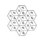
図1には、従来の無線セルラ通信システムの規則的な六角セル配列が簡略的に示される(脚注1)。周知のように、地理上のサービスエリアを六角格子として表現することによって幾何学的なパターンが確立されるが、これは、周波数をパターン化された配置(patterned disposition )に従って割当てることを許し、これによってこれら周波数を制御された反復的な規則的な割当てモデルに従って再利用(reuse )することが可能にされる。これらセルエリアは、おのおの、それらに割当てられた特定のチャネルセットを持つ(脚注2)。各チャネルセットは、そのセルエリア内で使用するための複数の個別の送信および受信無線チャネルから構成される。図1に示されるモデルにおいて、“A”とマークされたセルは、コーユーザセル(co-user cells )であり、全てが、同一のチャネルセットを使用する。このことは、“B”、“C”、などとマークされたコーユーザセルについても同様であり、これらのおのおのは、それ自身に割当てられたチャネルセットを持つ。
【0005】
各セルは、基地局と関連するアンテナシステムによって放射され、これら基地局は、互いにおよび/あるいは他の網と相互接続される。全方向放射パターンがアンテナ101によって示され、セルがより小さなV形タイプのサービスエリアにセクタ化された指向性アンテナパターンがアンテナ102によって表される。
【0006】
周知のように、セルラ通信システムの最も中心的な概念として周波数の再利用がある。周波数の再利用によって、異なる地理上の位置(異なるセル)内のユーザが、同一周波数のチャネルを同時に使用することが可能になるが、これが、図1に、規則的なチャネル割当ての場合に対して、共通の記号を持つセルとして示される。周波数の再利用は、システムのスペクトル効率を大幅に向上させるが、反面、適当なシステム設計がなされない場合は、同一チャネルを共通に使用するのに起因してセル間に重大な干渉を起こす恐れがある。
【0007】
周波数を再利用するための割当ては、一般には、コーユーザセルを識別するため、およびRFスペクトルをチャネルセットに分割するための単純な規則を採用することによって実現される。チャネル割当てアプローチは、二つの範疇、つまり、固定的(fixed )な割当てと、フレキシブル(flexible)な割当てに大別することができる。[これに関しては、M.Benveniste、“Self Configurable Wireless System"、forthcoming、を参照すること]。固定的なチャネル割当てにおいては、セルとそれらにサービスを提供するための(それらセルのために使用される)チャネルとの間の関係が固定される。あるセルに割当てられたチャネルは、そのセル内の呼のみをサービスすることができ、各チャネルは、それらチャネルを割当てられた全てのセルによって同時に使用することができる。固定的なチャネル割当ての一例として、“規則的(regular )”なチャネル割当てがあるが、これは、同一サイズの、規則的な間隔のセルを持つことを特徴とする。規則的なチャネル割当ては、セル間をトラヒックが一様に分配されるシステムに対しては、最適である。
【0008】
トラヒックの分布が一様でない場合には、チャネルをセルに、それらのトラヒック負荷に従って、割当てる最適の固定的、“不規則的(non-regular )”、なチャネル割当てを見つけることができる。[このような最適の不規則的な割当てを達成するためのプロセスが、M.Benvenisteによる“Apparatus and Method for Non-Regular Channel Assignment in Wireless Communication Networks”、合衆国特許第5,404,574号において開示されている]。
【0009】
フレキシブルなチャネル割当法は、システムの、基地局無線を遠隔からソフトウエアにて再チューニングするための能力を活用するが、この能力は、チャネル容量をトラヒック変動に適応させることを可能にする。フレキシブルなチャネル割当方法論のクラスには、適応的(adaptive)なチャネル割当て、動的(dynamic )なチャネル割当て、および、これら二つのハイブリッドである適応的動的(adaptive-dynamic)なチャネル割当てが含まれる[上に参照のM.Benvenisteの“Self Configurable Wireless System",id.を参照]。
【0010】
また、無線通信システム内の通信の品質は、受信信号の干渉に対する比(S/I比)に大きく依存することがよく知られている。問題となる主要な干渉は、二つの要素、つまり、コーチャネル干渉(co-channel interference )および隣接チャネル干渉(neighbor-channel interference )から成る。コーチャネル干渉は、動作中のチャネルと同一の周波数にチューニングされた通信源からの干渉であり、隣接チャネル干渉は、周波数スペクトルにおいて動作中のチャネルと近いチャネルを使用する通信源から来る。干渉隣接チャネルが、スペクトルにおいて動作中のチャネルと隣接する場合には、通常、隣接チャネル干渉(adjacent-channel interference )という用語が使用される。要求される音声あるいはデータ伝送品質を達成するためには、受信された信号の、コーチャネル干渉と隣接チャネル干渉の和に対する比が、指定される閾値以上であることが要求される。
【0011】
あるセル内および隣接セル内の隣接チャネルの使用を回避する必要性についてはよく知られている。一般的に、図2のセクタ化されたパターンによって示されるような、3セクタ−セルが、7−セルから成るクラスタ内のスペクトルを再利用し、同一セルをサービスするためのチャネル間の間隔が、21チャネル(630kHz)とされる、アナログAMPSシステムにおける従来のチャネル割当て法は、隣接チャネルからの干渉を無視できる程度にするのに十分である。物理的に隣接するセルに関しては、隣接チャネルセットが、同一セルの複数のセクタ、あるいは考慮下のセクタに隣接する隣接セル内の複数のセクタに割当てられるのを回避することで十分である。このようなチャネル割当てが、図2に示されるように、3−セクタセルが7セルのサイズのグループを再利用する構成に対して存在する。
【0012】
【発明が解決しようとする課題】
ただし、これよりは従来的でないチャネル割当てアプローチ、例えば、フレキシブルなあるいは不規則的で、かつ、固定的なチャネル割当てが追求される場合は、チャネル間隔要件のこのようなほぼ自動的な満足は、もはや起こらない。このようなアプローチにおいては、セルラシステム設計者は、ある一つのセル内あるいは隣接する複数のセル内で同時に使用されるチャネル間に要求される最小のスペクトル間隔について決定することを要求される。この問題に答えるために既に提唱されている様々なアプローチは、全くとはいわないまでも、十分には、隣接チャネル干渉について考慮していない(脚注3)。より具体的には、従来の隣接チャネル干渉の取り扱い、およびチャネル間隔要件の決定においては、S/I比に対する全体としての影響についての十分な考慮がなされていない。[例えば、W.C.Y.Lee によるMobile Cellular Telecommunications Systems、McGraw-Hill、New York、1989を参照されたい。]。このように、隣接チャネル干渉がS/I比に及ぼす影響が考慮されてないために、結果として、信号が、干渉より弱くなる場合が生ずる。コーチャネル干渉が存在しない場合は、受信機付近に位置する干渉信号の相対強度を、チャネル分離に起因する信号強度の低下とバランスさせることによって、結果としてのS/I比を1(0dB)にすることができるが、ただし、コーチャネル干渉が存在する場合は、結果としてのS/I比は、1以下(dBにて表現された場合は負)になる。
【0013】
S/I要件は、全体としての干渉を制限することを意味し、全体としての干渉は二つの項の和(つまり、コーチャネル干渉の項と隣接チャネル干渉の項の和)であるために、これらの間には、トレードオフが存在することとなる。つまり、隣接チャネル干渉の観点からは、チャネル間の周波数スペクトル間隔が大きくされると減少し、こうして、コーチャネル干渉に対するより大きなマージンを残すこととなる。結果として、より小さな再利用距離が可能になり、少なくとも原理上は、システム容量が高くなる。ただし、反面、より大きなチャネル間隔は、各セル内に使用できるチャネルの数を少なくし、これは、他の点が同一にとどまる場合は、容量を低減させることとなる。従って、システム設計者の一つの重要な目的は、S/I要件が満足され、かつ、スペクトル利用が最大になるような最適なチャネル間隔を決定することにある。
【0014】
【課題を解決するための手段】
本発明は、セルラ無線通信システム内の隣接チャネル干渉を、これらシステム内の通信チャネルのサービス品質係数の関数として、管理するための新規の複数の方法論を提供する。ここに開示される隣接チャネル干渉を管理するためのこれら新規の複数の方法論には:
【0015】
混合型パワー制御(Mixed Power Control )法−−従来のパワー制御法と関連する干渉問題を克服することを目的とする;
有向割当て(Directed Assignment )法−−無輻湊状態において隣接セル間の隣接チャネル衝突を低減することを目的とする;および
混合型パワー制御と有向チャネル割当ての併用(Mixed Power Control with Directed Assignment)法−−隣接セル間の隣接チャネル干渉を低減することを目的とする:
が含まれ、これらのおのおのが、本発明の一つの実施例を構成するものである。
【0016】
【発明の実施の形態】
以下の説明は、一部分、コンピュータシステム内のデータに関する演算のアルゴリズムおよび記号的表現の観点から行なわれる。明らかなように、これらアルゴリズム的記述および表現は、システムエンジニアリングの分野における技術者によって当業者に彼らの研究の内容を伝えるために通常に使用される手段である。
【0017】
ここで(および一般的に)使用されるアルゴリズムという用語は、要望される結果に導くための独立したステップのシーケンスと見ることができる。これらステップは、通常、物理量の操作を伴う。通常、必ずしもそうではないが、これら物理量は、蓄積、転送、結合、比較、その他の操作が可能な電気的あるいは磁気的な信号の形式をとる。説明の便利さ、並びに、通常の用法と適合させるために、これら信号は、しばしば、ビット、値、エレメント、記号、文字、項、数、その他の観点から説明される。ただし、これらおよび類似する用語は、適当な物理量と対応されるべきであり、これら用語は、これら量に与えられた単なる便宜上のラベルであるということが強調されるべきである。
【0018】
説明の明快さのために、本発明の実施例が個々の機能ブロック(“プロセッサ”とラベルされる機能ブロックを含む)から構成されるものとして説明される。これらが表す機能は、共有あるいは専用ハードウエアの使用を通じて提供され、これらには、これに限定されるものではないが、ソフトウエアを実行する能力を持つハードウエアが含まれる。例えば、図3および4内に示される“OMC”、“MSC”、および“BS”、並びに、図4の“コンピュータプロセッサ”機能の幾つかあるいは全ては、一つあるいは複数のプロセッサによって提供され、これらプロセッサには、共有プロセッサも含まれる。(“プロセッサ”という用語の使用は、ソフトウエアを実行する能力を持つハードウエアを排他的に差すものと理解されるべきできない)。
【0019】
一例としての実施例は、マイクロプロセッサおよび/あるいはデジタル信号プロセッサ(DSP)ハードウエア、例えば、AT&T DSP16あるいはDSP32C、以下に説明される動作を遂行するためのソフトウエアを蓄積するための読み出し専用メモリ(RAM)、および結果を蓄積するためのランダムアクセスメモリ(RAM)を含む。大規模集積(VLSI)ハードウエア実施例、並びに、カスタムVLSI回路と汎用DSP回路との組合せを使用することも可能である。
【0020】
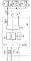
図3には典型的なセルラシステムがブロック図にて示される。図示されるように複数の移動交換センタ(MSC)202および203によって移動無線電話システムが公衆交換電話網201(PSTN)に接続される。MSCの交換によって、おのおのがセルカバーエリアにサービスを提供する複数の基地局(BS)210が相互接続される。各カバーエリアは、図示されるように、実際のシステムに典型的な不規則な境界を持つ。各BSは、そのセルカバーエリア内の移動無線電話250にサービスを提供するための無線送/受信装置および放射アンテナを持つ。
【0021】
運転および管理センタ(OMC)220が、それらのシステム動作およびそれらと関連するBS210を制御するためにMSC202および203に結合される。OMC220は、中央制御局であり、これは、データ処理部、データメモリから入力されるデータを受け入れるための入力、およびリアルタイムコントロールを含む。フレキシブルなチャネル割当ての場合は、このデータ処理構成が、BSの所に位置する遠隔からチューニング可能な無線トランシーバとの組合せにてチャネル割当て(アレンジメント)を実現するために使用される。
【0022】
このようなフレキシブルなチャネル割当てに対しては、図4に略ブロック図にて示されるような、BSの所の無線トランシーバのチャネル割当ておよびチューニングを制御するためのデータ処理装置の一例としての実現が、OMC内に含まれる。コンピュータプロセッサ310は、関連するメモリ311内に蓄積されたプログラムを持つ。このプログラムは、セルラシステムへの無線チャネルの割当てを遂行するためのインストラクションを含む。初期入力データが入力機能312を通じてコンピュータプロセッサ310に供給される。これら入力には、利用可能なセル、利用可能な無線周波数、および干渉情報が含まれる。干渉情報は、通常、セル間干渉マトリックス(cell-to-cell interference matrix)の形式を持ち、他のセルからの各セルへの干渉を定義する。これら入力には、さらに、要望されるチャネル割当ておよびトラヒック利用パターンに対して要求されるシステム制約が含まれる。
【0023】
フレキシブルなチャネル割当て方法論を実現するために、チャネル割当てプロセスが、コンピュータプロセッサ310によって、メモリ311内に蓄積されたインストラクションに従って遂行される。結果としてのチャネル割当てが出力機能313を介してMSC315に出力され、これはここからBS321に転送される。これらBS内に含まれる個々のチューナブル無線322が、次に、割当てプロセスによって決定された無線チャネルの割当てに従って適当な周波数にチューニングされる。
【0024】
I.発明の方法論
A.概要
本発明の方法論が、ここでは、複数の実現(実施例)として示されるが、これら新規の方法のおのおのが、隣接チャネル干渉を管理し、結果として、総合的なS/I比目標を達成することを目標とする。これら実施例の具体的な説明から明らかになるように、各実施例は、独立して実現することもできるが、これらの殆どは、一つあるいはそれ以上の他の実施例と組み合わせて実現することも、あるいは、参照として示された一連の関連する特許出願において開示される方法論の実施例と組み合わせて実現することも可能である。
【0025】
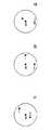
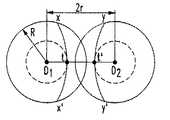
隣接チャネル送信機に起因する干渉のレベルは、加入者ユニット(通常は、移動あるいは携帯ユニット)のそれらの基地局からの位置、実施されるパワー制御のレベル、および通信の方向、つまり、送信が基地局から加入者ユニットに向けて行なわれるか(ここでは、“ダウンリンク”と呼ばれる)、あるいは加入者ユニットから基地局に向けて行なわれるか(ここでは、“アップリンク”と呼ばれる)に依存する。図5および6は、隣接チャネル干渉の影響について考察するための一例としての構成を示す。図5には、単一のセルが、基地局Bと共に示され、図6には、二つの近隣するセルが、基地局B1 およびB2 と共に示される。両方の図面において、加入者局iおよびjが、互いおよび基地局との様々な位置関係にて示される。全ての構成において、記号iは、サービス中の加入者ユニットを示し、記号jは、その周波数スペクトル内で最も近い隣接チャネルと呼ばれるチャネル上で動作している加入者ユニットを示す。図6の構成においては、サービス中の加入者ユニットiは、基地局B1 によってサービスされ、隣接チャネル加入者ユニットjは基地局B2 によってサービスされる。
【0026】
一例として、全ての呼が同一のパワーにてサービスされる場合、つまり、パワー制御が適用されない場合について考える。この場合、結果として、ダウンリンク上の隣接チャネル干渉は、図5に示される全てのケースについて、全ての呼が同一のパワーにてサービスされるために同一となる。一方、アップリンク上の隣接チャネル干渉は、図5に示される3つのケースでおのおの異なる。信号の減衰が送信機と受信機との間の距離が増加すると増加するために、図5aにおいては、加入者ユニットiから受信される信号強度は、加入者ユニットjからの干渉信号よりも(加入者ユニットiがサービスを提供する基地局に近いために)強くなる。従って、この構成においては、アップリンク上の隣接チャネル干渉は無視できる。図5bの構成においては、受信サービス信号は、干渉信号と、二つの加入者ユニットが基地局から同一の距離にあるために、同一となる。最後に、図5cの構成においては、アップリンク上の隣接チャネル干渉の方が、干渉加入者ユニットがサービス加入者ユニットよりも基地局に近いために高くなる。
【0027】
基地局により近い呼のパワーを低減するパワー制御が使用された場合は、経験される隣接チャネル干渉の関係は変化する。これら変化を再び図5の構成を用いて説明するが、ここでは、パワーが、受信サービス信号が等しくなるように調節されるものと想定される。この場合、結果として、アップリンク上の隣接チャネル干渉は、図5の3つの全ての構成において、全ての加入者ユニットから受信される信号が、そのユニットの基地局からの位置と無関係に同一となるために、同一になる。反対に、ダウンリンク上にパワー制御が適用された場合は、隣接チャネル干渉は、3つの構成のおのおのに対して異なることになる。つまり、パワー制御のために、図5aの構成においては、ダウンリンク上の隣接チャネル干渉は、干渉信号のパワーがサービス信号のパワーよりも高くなるために増加することとなる。図5bの構成においては、サービスされる加入者ユニットと隣接チャネル加入者ユニットが基地局から等距離にあるために、パワー制御が、ダウンリンク上の隣接チャネル干渉に影響を与えることはない。最後に、図5cの構成においては、パワー制御によって、ダウンリンク上の隣接チャネル干渉は低減される。従って、以上からわかるように、パワー制御は、一般的には、アップリンク方向に対しては有用であるが、ダウンリンク方向において使用された場合は、しばしば、結果として、隣接チャネル干渉を増加させることとなる。
【0028】
図6に示されるような隣接セルの場合についても考える。最初に、図6aの構成についてみると、加入者ユニットiは、ダウンリンク上(基地局B2 からの競合信号に起因)、およびアップリンク上(加入者局jからの競合信号に起因)の両方で隣接チャネル干渉を受ける。図面から簡単に理解できるように、図6bにおけるダウンリンク上および図6cにおけるアップリンク上には同程度の隣接チャネル干渉が発生するが、ただし、図6bにおけるアップリンク上および図6cにおけるダウンリンク上では、隣接チャネル干渉は、無視できる程度となる。
【0029】
参照の本発明と対を成すM.Benveniste-7(S/N08/580570)と呼ばれる特許出願においては、チャネル間隔(サービスチャネルと干渉隣接チャネルとの間の間隔)、サービスチャネルと干渉チャネルの受信信号強度、およびS/I比との間の幾つかの関係が展開され、次に、これら関係が一例としての無線通信用途に対して適用され、サービス信号と干渉信号の間の様々なレベルの相対信号強度に対して実現されるS/I比とチャネル間隔との間の関係を示す二つのテーブルが作成されている。後に説明される複数の干渉管理法にとって有用な基準を提供するこれらテーブルが以下に再生されるが、これは、次のような特徴を持つ。つまり:
テーブル1は、18dBの設計コーチャネルS/I閾値が使用された場合のサービスされる加入者によって実現されるS/I比Tと、チャネル間隔wとの間のトレードオフを提供する。
【0030】
テーブルからわかるように、第一のカラムは、チャネル帯域幅の倍数にて与えられたチャネル間隔を表し、一方、残りの10のカラムは、加入者によって経験されるサービス信号に対する干渉信号の(dBにて表されたときの)信号強度の比の様々な値に対するサービスされる加入者によって実現されるS/I比(dBにて表現)を与える。
【0031】
同様に、テーブル2は、異なるチャネル間隔値wに対する目標の総合S/I比Tを達成するために必要とされる設計コーチャネルS/I比Tc 、つまり、dB(T)が18dBであるときのTc とwとの間のトレードオフを提供する。
【表1】
【0032】
【表2】
【0033】
前述のように、パワー制御が適用されず、加入者ユニットiとjの両方が同一の基地局によってサービスされる場合は(つまり、図5の構成においては)、ダウンリンク上では、干渉信号とサービス信号は、各信号が基地局から同一のパワーにて送信されるために同一になる。従って、干渉信号のサービス信号に対する比Pは、1となり、dB(P)は0となる。テーブル1からわかるように、隣接チャネルが使用された場合は、S/I比は、16.23dBに低下するが、これは、目標値63.1(18dB)の67パーセントを意味する。ただし、チャネル間隔wを2に設定することで、隣接チャネル干渉に起因するS/I低下が殆ど矯正でき、S/I比は、16.23dBから17.99dBに増加する。
【0034】
加入者ユニットiとjが異なる基地局によってサービスされている場合も、図6aおよび6bに示されるように、サービス中の加入者ユニットiが二つのセルの共通境界の付近に位置するときは、干渉加入者ユニットjの位置と無関係に、類似する状況が発生する。ただし、図6cに示されるように、加入者ユニットiが、干渉基地局B2 から、サービスを提供する基地局B1 からよりも遥かに離れて位置する場合は、P比は、1より小さくなり、dB(P)は負となる。従って、隣接チャネルの使用が、S/I比に与える影響は、小さくなる。例えば、dB(P)の値が−5dBである場合は、テーブル1から、17.36dBのS/I比が実現されることが示される。これは、設計コーチャネルS/I比18dBの86パーセントに相当する。dB(P)が−10dBの場合は、17.79dBのS/I比が実現され、これは、設計コーチャネルS/I比の95パーセントに相当する。見かたをかえれば、この値は、隣接チャネル干渉が、コーチャネル干渉と隣接チャネル干渉を総和して5パーセントに制限された場合に、S/I比によって実現される値として特性化することもできる。従って、Pの値は、それに対して隣接チャネル干渉が許容可能になる値として定義することもできる。こうして定義された値は、ここでは、Pa と呼ばれ、この一例としてのケースにおいては、−10dBである。
【0035】
テーブル2に示されるwとTc との間のトレードオフについて、dB(P)=0の場合に関して考察すると、チャネル間隔を1から2に増加することによって、計画コーチャネルS/I比として、21.03dBの代わりに18.01dBを使用することが可能になることがわかる。また、テーブルから、間隔を2よりさらに増加しても、コーチャネル干渉制約、従って、容量の観点からは、全く得るものがないことがわかる。
【0036】
パワー制御が適用された場合は、前述のように、ダウンリンク上のパワー制御は隣接チャネル干渉の影響を悪化させる。ここでは、互いに接近して位置する二つの加入者ユニットの信号強度を低減するためにダウンリンク上にパワー制御が適用される場合の特定のケースについて考察する。このケースにおいては、Pは、これら二つの加入者ユニットをサービスする信号のパワー低減の差に等しくな。最悪の場合が、図5aの構成によって示されるように、加入者ユニットiをサービスする信号のパワーが大幅に低減され、加入者ユニットjをサービスする信号が最大のパワーにて動作する場合に発生する。この場合、テーブル1からわかるように、設計コーチャネルS/I比が18dBであっても、近い方の加入者ユニットに対してダウンリンクパワーが28dBだけ低減されると、実現されるS/I比は負となり、17.79dBのS/I比を達成するためには、チャネル間隔3が必要となる。
【0037】
以降のセクション(節)B1においては、新規の混合型パワー制御方法論(Mixed Power Control Methodolgy)について開示されるが、これは、ダウンリンク上に部分的なパワー制御を使用し、チャネル間隔を2の値以上にすることなしに妥当なS/I比を維持することを可能にする。
【0038】
B.隣接チャネル干渉を管理するための方法論
以下の節においては、3つの新規の干渉管理方法論について説明されるが、これらは、従来の技術による様々な方法によって達成されるそれと比べて隣接チャネル干渉を低減させる。これら新たな干渉管理方法論は、各々が本発明の一つの実現(実施例)を構成し、それぞれ、混合型パワー制御法(Mixed Power Control)、有向割当て法(Directed Assignment)法、および混合型パワー制御と有向割当ての併用法(Mixed Power Control With Directed Assignment)と称される。
【0039】
B.混合型パワー制御法
従来の様々なパワー制御法の適用(あるいは非適用)と、サービスされる加入者によって経験される隣接チャネル干渉との間の関係についての前の議論において、これら干渉が伝送の方向によって(ダウンリンクかアップリンクかによって)、並びに、サービスされる加入者ユニットの、付近の他の加入者ユニットに対する位置、および付近のサービスを提供するおよび/あるいは他の基地局に対する位置によってばらつくことが示された。以下では、このばらつきを大幅に改善する新規の混合型パワー制御方法論について述べられる。説明から明らかになるように、この混合型パワー制御方法論は、単独にて実現することもできるが、ただし、これは、ここにおいて、および、対の参照された特許出願において開示されている他の新規の幾つかの干渉を管理するための方法論に組み込むことも可能である。
【0040】
この新規の混合型パワー制御方法論は、ダウンリンクの場合と、アップリンクの場合を切り離して扱い、この方法論を、こうして分けられた個々のケースについて説明することによってより良く理解できるものである。
【0041】
(a)ダウンリンク上のパワー制御
パワー制御の一般的な説明において、従来のパワー制御方針がダウンリンク上に適用された場合、つまり、基地局付近の加入者ユニットに対して受信信号強度が低減された場合、隣接チャネル干渉の影響が悪化されることが示された。この場合は、干渉信号のサービス信号の強度に対するの比、P(dBにて表現)は、二つの加入者ユニットをサービスする信号のパワーの低下の差に等しくなる。最悪の場合が、図5aの場合のように、加入者ユニットiをサービスする信号のパワーが大幅に低減され、加入者ユニットjをサービスする信号が最大のパワーにて動作する場合に発生する。テーブル1に反映される一例としてのケースにおいては、18dBの設計コーチャネルS/I比が使用された場合でも、実現されるS/I比は、コーチャネル間隔が使用される近い方の加入者ユニットに対してダウンリンク上のパワーが約28dB低減された場合は(この構成においては現実的な低減)、負になることがわかる。
【0042】
後に説明されるように、パワー低減の規模が制限された場合は、パワー制御を使用することによって、チャネル間隔の値を2以上に増加することなしに妥当なS/I比を達成することが可能となる(パワー制御が行なわれない場合は、チャネル間隔の増加が必要となる)。テーブル1から、干渉信号とサービス信号の間のdBにて表現された場合の信号強度の差P、あるいは、等価的に、二つの加入者ユニットに対するパワー低減の相対差が、14dB以下である場合は、パワー制御がS/I比に与える影響は小さいことがわかる:つまり、チャネル間隔2にて、17.79dBのあるいはそれ以上のS/I比が実現できることがわかる。従って、パワー制御を制限し、サービスされる加入者に対する受信信号強度を、サービスされる加入者位置における干渉信号のレベルより14dB以下には落ちないように維持することによって、チャネル間隔を2に維持し、しかも、隣接チャネル干渉を無視できる程度にすることが可能である。相対的なパワー制御差に対するこの制約は、ここでは、リミティングパワー制御比(limiting power control ratio)と呼ばれ、しばしば、χM によって表される。テーブル1によって示される一例としてのケースにおいては、dB(χM)は、−14dBである。
【0043】
この混合型パワー制御方法論の一例としての実施例においては、パワー制御は、セルの外周と、χM だけ低減された信号がセルの外周の所で受信される信号と等しくなるセルの半径上のポイント、との間に位置する加入者ユニットに対して適用される。基地局からセルの半径に沿っての、χM だけ低減された信号がセルの外周で受信される信号と等しくなる所のポイントまでの距離が、lM として定義される。従って、パワー制御は、1M と、セルの外周、との間に位置する加入者ユニットに対して適用されることとなる。図7aは、混合型パワー制御方法論のこの一例としての実施例においてダウンリンク上に受信される信号を基地局からの加入者ユニットの距離の関数として示す。
【0044】
(b)アップリンク上のパワー制御
ダウンリンクの場合と異なり、パワー制御は、一般的には、アップリンク方向に対しては隣接チャネル干渉を低減するのに有効であることが知られている。しかしながら、後に説明されるように、本発明の混合型パワー制御方法論がアップリンクに対して適用される場合は、セルのある領域内では、隣接チャネル干渉に悪影響を与えることなしに、パワー制御を排除することが可能になる。
【0045】
アップリンク通信の場合は、Pの値は、パワー制御によって低減することができ、dB(P)は、サービス信号と干渉信号の間の信号減衰の差からパワー低減の差を引いた値となる。この関係およびこの影響は、基地局に送信する二つの加入者ユニット間の信号減衰が40dBであり、パワー低減に起因する受信信号レベルの差が12dBであるような構成によって説明することができる。この場合は、dB(P)=40−12=28dBとなる。18dBの設計チャネルS/I比、およびチャネル間隔2が使用された場合、テーブル1から、14.46dBのS/I比が実現されることが示される。一方、パワー低減差が26dB(P)に増加された場合は、dB(P)は14dBとなり、チャネル間隔2に対しては、総合S/I比は、17.79dBになることがわかる。
【0046】
この関係から、14dB以下のdB(P)値では、チャネル間隔2が使用された場合は、隣接チャネル干渉は殆ど発生せず、従って、高い信号減衰を受けている潜在的に干渉を与える可能性を持つ加入者ユニット、例えば、セルの境界付近の加入者ユニットには、パワー制御を適用する必要はないということができる。セル内の可能な最大の減衰(maximum possible attenuation)より14dB低い信号減衰を持つ加入者ユニットのみがそれらの信号を低減されることを必要とされる。つまり、パワー低減は、基地局と、受信される信号強度のセル内の最小信号強度に対する比がχM-1 となるセルの半径上のポイントlM 、との間に位置する加入者ユニットに対して適用することのみが必要とされる。(脚注4)。テーブル1の一例としてのケースにおいては、dB(χM-1 )は、14dBである。図7bは、この混合型パワー制御方法論が使用された場合のアップリンク上の受信信号を基地局からの加入者ユニットの距離の関数としてグラフ的に示す。
【0047】
任意のチャネル間隔に対して、アップリンク上に混合型パワー制御方法論によって必要とされるパワー低減能力を推定するためには、ある統計的な有意にて遭遇されるべきPの最高値が必要になる。本発明人は、関連する文献[M.Benveniste,“Managing Neighbor Channel Interference in Channelized Cellular System,"forthcoming] において、伝送損失係数が4(移動無線システムに対して一般に受け入れられている値)である場合は、パワー制御なしでは、0.995の確率で、相対信号強度dB(P)が40dB以下となることを示している。従って、チャネル間隔2の場合は、
【0048】
最大減衰(40)−dB(P)閾値(14)=最大パワー低減(26dB)となるために:
26dBのパワー低減能力−dB(φM )で十分である。
【0049】
テーブル2からわかるように、あるレンジのパワー制御オプションが提供される。これらオプションの例としては、近い方の加入者ユニットのパワーを20dBだけ低減し、遠い方の加入者ユニットを最大パワーにとどめるオプションが含まれる。このオプションにおいては、チャネル間隔2の場合は、設計コーチャネルS/I閾値として、18.97dBが必要とされる。別の可能性としては、近い方の加入者ユニットのパワーを26dBだけ低減する(遠い方のユニットは最大パワーにて動作する)ことが考えられる。このオプションにおいては、14(40−26)のdB(P)値が与えられるが、これは、チャネル間隔2に対しては、18.22dBの設計コーチャネルS/I閾値を必要とする。
【0050】
これも明らかになるように、混合型パワー制御方法論のここに説明される幾つかの実施例に対しては、パワー制御要件は、チャネル間隔要件が最小になるように選択される。この方法論の他の用途(適用)も、勿論、存在する。例えば、より大きなパワー低減レンジが要望される場合は、チャネル間隔が増加される。後者の考えは、パワー制御を能力を増加させるための手段として採用する動的チャネル割当てアルゴリズムに対しては効果的である。
【0051】
B.2 有向割当て
隣接チャネル干渉の代用として、二つの隣接チャネルが同一あるいは隣接するセル内で同時に使用されたときに発生する隣接チャネル衝突(adjacent-channel conflicts)の数が使用できる。前の議論から明らかのように、全ての隣接チャネル衝突が隣接チャネル干渉を発生されるわけではないが、それでも、隣接チャネル衝突の数を低減すると、隣接チャネル干渉の尤度が低減すると一般的に述べることができる。
【0052】
この節において説明される本発明の実施例は、隣接チャネル衝突の確率を低減することによる隣接チャネル干渉の最小化に向けられる。このアプローチは、規則的あるいは不規則的な、および固定的なあるいはフレキシブルな全てのチャネル割当てに対して適用可能であり、さらに、セクタ化されたあるいは全方向性のセルの両方に対して適用可能である。これは、さらに、他の隣接チャネル干渉を低減するための様々なアプローチと組み合わることも可能である。
【0053】
有向割当て方法論は、規則的かつ固定的なチャネル割当てからの単純な例を使用することによってより良く理解できるものである。図8に示されるように、4つのセルに、チャネルセット:A、B、C、およびDが割当てられる場合を考える。各セットを構成するチャネルは、他の3つのセットの二つのチャネルに隣接するものと想定され、さらに、各セルは、他の3つのチャネルセットを割当てられたセルに隣接するものと想定される。さらに、この一例としての例に対しては、24のチャネルが利用可能であり、問題の4つのセルが、それぞれ、5、3、4、および3個の進行中の呼を持つものと想定する。図8Aに示されるように、全ての呼に対して低い番号のチャネルが割当てられた場合は、セルA内には4つ、B内には3つ、C内には3つ、そしてD内には4つの隣接チャネル衝突が発生することとなる。隣接チャネル衝突の数を減らすためには、図8Bに示される構成のように、セルAおよびセルC内の全ての呼が利用可能な最低の番号のチャネルに移動され、そして、セルBおよびセルD内の全ての呼が最高の番号のチャネルに移動される。結果として、隣接チャネルを含むセル内のアクティブなチャネル間により大きなチャネル間隔が存在することとなる。図8Bに示されるように、隣接チャネル衝突の数は、4つのセルに対して、それぞれ、2、2、1、および2に低減される。
【0054】
有向割当て方法論を遂行するために従われるステップは以下の通りである:
1.利用可能なチャネルがチャネルセットの間で、各セットが、“+”あるいは“−”のラベルを持ち、さらに、隣接チャネルを持つ任意の二つのセットが反対のラベルを持つように分配される。
2.各セルにも、ラベル“+”あるいは“−”が割当てられる。
3.セルはそのセルと同一のラベルを割当てられた一つあるいは複数のセットからのチャネルを使用することができる。
4.“+”のラベルを持つセルは、それらのユーザに利用可能な最低の番号のチャネルを割当て、一方、“−”のラベルを持つセルは、それらのユーザに利用可能な最も高い番号のチャネルを割当てる。
【0055】
ステップ4は、反対のラベルを持つセル内のアクティブなチャネルのチャネル間隔を増加させる。ステップ1のために、隣接チャネルは、反対のラベルを持つセル内にのみ見られるために、隣接チャネル衝突の尤度が低減される。
【0056】
呼をチャネルセットのいずれかの端に押しやるための2つのオプションが存在する。第一のオプションにおいては、“+”のセル内の最も高い番号のチャネルからの呼(あるいは“+”のセル内の最も低い番号のチャネルからの呼)が、そのセル内の出呼のチャネルに移動される。こうして、最高でも、呼の終端あるいはハンドオフ当たり、1チャネルの再構成のみが必要とされる。チャネルの再構成を必要とすることなくユーザをチャネルセットの正しい端に保つための第二のオプションにおいては、入り呼が、“+”のセルに対しては最も低い番号の空きチャネルに割当てられ、“−”のセルに対しては最も高い番号の空きチャネルに割当てられる。
【0057】
有向割当て方法論は、固定的およびフレキシブルな両方のチャネル割当てに適用することができる。ただし、チャネルセットの翻訳は、二つのアプローチで異なる。固定的なチャネル割当ての場合は、チャネルセットは、異なるセルに専用に使用されるチャネルの互いに素なグループである。一方、全てのチャネルセットが同一のサイズを持つ固定的でかつ規則的なチャネル割当てにおいては、ステップ1は、偶数のチャネルセットが存在することを要求する。
【0058】
フレキシブルなチャネル割当てにおいては、(隣接チャネル使用の制約を遵守するために)二つのチャネルセットが必要とされ、各チャネルセットに、“+”あるいは“−”のラベルが割当てられる。例えば、奇数番号のチャネルのチャネルセットに“+”のラベルが与えられ、偶数番号のチャネルのセットに“−”のラベルが割当てられる。“+”ラベルのセルは、低いチャネル番号を優先し、“−”ラベルのセルは、高いチャネル番号を優先するために、低トラヒック状態においては、異なるラベルを持つセルの話中チャネル間の間隔が増加する。隣接チャネルは異なるラベルのセル内においてのみ使用されるために、隣接チャネル衝突の確率が低減される。
【0059】
B3.混合パワー制御と有向割当ての併用
ダウンリンク上にはパワー制御を用いずアップリンク上には全パワー制御を用いることを特徴とするパワー制御方針に対しては、チャネル間隔2を使用することで、セル内の隣接チャネル干渉の影響を、このパワー制御方針と併用して、十分に低減できることが示された。関連する前に参照されたBenveniste-8(S/N 08/580568)と称される特許出願においては、このようなパワー制御方針に対しては、セル内に、ダウンリンクについては、隣接セルからの隣接チャネル干渉からの影響が無視できるような領域が存在することが示されたが、加入者ユニットが隣接セルに対して、アップリンク上に隣接チャネル干渉を殆ど与えないような類似する領域が存在する。より詳細には、図11(Benveniste-8特許出願の図7に対応)に示されるように、セル1内の輪郭XX’の左に位置する加入者ユニットは、セル2内に使用される隣接チャネルからのダウンリンク干渉を受けることはない。同様に、輪郭YY’の右に位置する加入者ユニットは、セル1に対してアップリンクの隣接チャネル干渉を与えることはない。
【0060】
さらに、反対のパワー制御が実施された場合、つまり、ダウンリンク上で全パワー制御が使用され、アップリンク上でパワー制御が使用されない場合は、同一セル内のユーザから与えられる隣接チャネル干渉が増加し、このために、これは回避されるべきであることが示される。ただし、“混合型パワー制御(mixed power control )”として特性化される新規のパワー制御方針が、セクションB1において説明されているが、この方針は、ダウンリンク上の制限されたパワー制御を許し、同時に、隣接チャネル干渉を許容限度内に維持する。より詳細には、パワー制御は、ダウンリンク上では、最大パワー低減レンジχM に対応する半径lM (説明のケースにおいては、lM は、14dBのパワー低減に対応する0.4467R)の外側においてのみ使用することが許される。同様に、説明される混合型パワー制御方針下では、アップリンク上では、パワー制御は、受信信号がセル内の最も低い受信信号より14dB高いレベルに等しくなる半径lM の内側にのみ適用される。こうして受信される信号が図7に、通信の両方向に対して、ユーザから基地局までの距離(対数スケール)の関数として示される。この混合型パワー制御方針を使用した場合は、チャネル間隔2で、十分にセル内の干渉を回避することができる。
【0061】
理解できるように、純粋なパワー制御方針から逸脱することに対する動機は、隣接セル内での隣接チャネルの使用の影響を低減し、これによって、隣接セルに対する隣接チャネル制限を低減することである。上に説明の混合型パワー制御方針を図9に示される隣接セル構成に適用することを考える。この図に示されるように、隣接セルからの隣接チャネル干渉に弱い領域を定義する単一の輪郭XX’の代わりに、図10に示されるように、おのおのが隣接セル内で使用されるパワーレベルkに対応するこれら輪郭のファミリXKXK’が存在する。輪郭X1X1’は、セル2内で使用される最強のパワー信号に対応する。輪郭XKXK’は、輪郭XX’の右側および左側の両方に広がる。右へのシフトは、セル1内のパワーレベルkにてサービスされているセル2内のユーザから隣接チャネル干渉を受けるユーザの割合を減少するが、左へのシフトは、これを増加させる。ただし、ここでは、二つのセル内のユーザが、隣接チャネル上で、隣接チャネル干渉の尤度が低減されるような方法にて動作するようにマッチングされる。
【0062】
ユーザのマッチングによって隣接チャネル干渉がどうして低減できるかを説明するために、図10内のユーザM1 について考える。パワー制御がない場合は、M1 は、ユーザの隣接チャネル上の位置に関係なく隣接チャネル干渉を受ける。一方、パワー制御が使用された場合は、M1 は、低いパワーレベルkにてサービスされるセル2内のユーザと、隣接チャネル干渉が起こらないようにマッチングすることができる。こうして、隣接チャネル干渉の確率を、制限されたパワー制御と、隣接セル内の隣接チャネルユーザの選択的なマッチングを組み合わせて使用することによって低減することができる。この目的を遂行するためのチャネルマッチングアルゴリズムについて以下に説明される。
【0063】
パワー制御のレンジによって、XKXK’輪郭の広がりが決定される。隣接チャネル干渉の確率を最小にするパワー制御の最適レンジは、採用される特定のチャネルマッチングアルゴリズムとの関連で決定されるべきである。ダウンリンク上のパワー制御のレンジは、χM を超えることはできないことに注意する。
【0064】
前述のように、本出願人は、ゼロの隣接チャネル干渉を達成するためのアップリンク要件は、上に説明されたダウンリンク要件と、これら二つのリンク上に補間的なパワー制御方針が使用された場合は、対称的であることを示している。[M.Benveniste,“Managing Neighbor Channel Interference in Channelized Cellular Systems",idを参照]。つまり、アップリンク上のパワー制御が半径lMの円の内側に制限され、この円の外側ではパワー制御が存在しない場合は、セル1内のユーザの異なるパワーレベルに対応するk個の、セル2内のユーザがセル1内の対応するユーザにアップリンク干渉を与えない領域を定義する輪郭YKYK’のファミリが存在することとなる。これら輪郭は、セル1内のダウンリンクの場合に対して描かれた輪郭XKXK’の鏡像である。この参照文献において、出願人は、さらに、隣接セル内の隣接チャネルユーザにアップリンク方向の隣接チャネル干渉を与えないユーザは、隣接セルユーザからのダウンリンク方向の隣接チャネル干渉を受けないことを示している。隣接チャネル干渉をなくするための条件のこの対称性のために、ユーザマッチングアルゴリズムは、片方の通信方向についてのみ分析するのみで十分である。従って、以下の節において説明される方法論は、ダウンリンクのみに焦点が置かれる。アップリンク上の性能は、これと同等であるとみてよい。
【0065】
(a)方法論の説明
前の節において示されたように、隣接チャネル干渉の確率は、隣接セル内の隣接チャネルユーザを正しくマッチングすることによって低減することができる。このユーザマッチング問題は、複雑な組合せ最適化問題であるが、ただし、以下に説明される単純な発見的アルゴリズムによってこの問題の良好な解に到達することが可能である。
【0066】
このアプローチは、各セル内のユーザに順番を与えることから開始される。順番を付けられたユーザに、チャネル番号の昇順(あるいは降順)に利用可能なチャネルが割当てられ、これによって、隣接チャネルユーザがマッチングされる。従って、目的は、あるセル内のユーザを、隣接チャネル干渉の確率が最小になるように、ランクするための基準を決定することにある。サービスを提供する基地局からのユーザの距離が、ランキング基準として選択される。
【0067】
ユーザと基地局との間の距離をランキング基準として選択するためのこの論理は、図10の2−セルの例について考察することによって理解することができる。以降の議論においては、以下の記号が使用される。つまり:
mi は、加入者ユニットMi の自身の基地局からの距離を表し、
ni は、加入者ユニットMi の隣の基地局からの距離を表す。
出願人の関連する文献においては、ダウンリンク方向におけるパワー制御の適用に対しては、隣接チャネル干渉は、以下のときに発生しないことが示される:
【数1】
【0068】
本発明の方法論は、一つ以上の隣接セルによる隣接チャネルの使用の問題を扱うが、以下のように一般化することができる:
1.利用可能なチャネルがチャネルセット間で各セットが“+”あるいは“−”のラベルを持ち、隣接チャネルを持つ任意の二つのセットが反対のラベルを持つように分配される。
2.各セルに“+”あるいは“−”のラベルが割当てられる。
3.セルは、そのセルと同一のラベルを割当てられた一つあるいは複数のセットからのチャネルを使用することができる。
4.各セル内のユーザには、サービスを提供する基地局からの距離の降順にチャネルが割当てられる。“+”のラベルを持つセルは、それらのユーザに最初に最も低い番号のチャネルを割当て、一方、“−”のラベルを持つセルは、それらのユーザに最初に最も高い番号を持つチャネルを割当てる。
【0069】
ステップ1からステップ4によって、隣接チャネルは反対のラベルのセルによってのみ使用されるために、高パワーのユーザを、“+”のセル内では、低い番号のチャネルに割当て、一方、“−”のセル内では、高い番号のチャネルに割当てることによって、これらの間のチャネル間隔が増加される。結果として、高パワーのユーザは、(低トラヒック状態においては)アイドルなチャネルのとなりで動作するか、あるいは、その基地局付近の隣のセルのユーザに割当てられたチャネルの隣で動作し、こうして、隣接セル間の隣接チャネル干渉の確率が低減される。
【0070】
理解できるように、ここで説明される方法論は、幾つかの点で、前に説明された有向割当て方法論に類似する。ただし、有向割当て方法論は、輻湊状態においては隣接チャネル干渉になんの効果ももたないが、パワー制御を適当なユーザマッチングとともに使用した場合は、輻湊状態においても、隣接チャネル干渉の確率を低減できる。
【0071】
理解できるように、上に説明されたマッチング手続きの有効性は、輪郭XKXK’がどの程度広がっているかに依存する。これは、一方、隣接チャネル干渉の確率を最小にするために選択されたパワー制御のレンジに依存する。
【0072】
有向割当ての場合のように、ユーザは、以下の二つの方法によって空いたチャネルセットのどちらかの端に詰めることができる。第一の方法においては、呼が去ったときのチャネルの再構成を伴い、第二の方法はこれを伴わない。さらに、チャネルの再構成が、ユーザの移動と共に変化するユーザの正しいランキングを維持するために必要とされるが、別の方法として、チャネルの再構成を、隣接チャネル干渉が観察されるまで延期し、これによって必要とされる再構成の数を低減することも考えられる。
【0073】
(b)方法論の適用
ここに説明される方法論は、固定的およびフレキシブルな両方のチャネル割当てに対して使用することが可能である。この節においては、固定的かつ規則的なチャネル割当てに対するこの方法論の一例としての適用について説明される。フレキシブルなチャネル割当てに対してこの方法を使用する例については、M.Benveniste,A.G.Greenberg,およびP.E.Wrightによる“On dynamic channel assignment in wirelss system:Extensions of Ordered Borrowing",forthcoming.、において説明されている。
【0074】
図11に示されるN=8のパターンが繰り返される全方向性セルのシステムについて考察する。チャネルセットが水平方法によって構成され、従って、各セルが、隣接チャネルを割当てられた一つの他のセルとの境界を共有するものと想定される。400のチャネルが与えられた場合、各セルには、50のチャネルが割当てられることとなる。テーブル3は、チャネルマッチングの隣接チャネル干渉に対する影響を申し出負荷の関数として示す。チャネルがランダムに割当てられた場合は、シミュレーションによって、隣接チャネル衝突(adjacent-channel conflict,ACC)の確率は、40.3アーランの申し出負荷の場合(これは、2%の閉塞確率を与える)、79%となり、隣接チャネル干渉(adjacent-channel inteference ,ACI)の確率は、10.6%となることが示される。また、有向割当て方法論が適用された場合は、同一の申し出負荷および閉塞確率に対して、隣接チャネル衝突の確率は、73%に低下し、隣接チャネル干渉の確率は、10.1%となり、さらに、パワー制御がユーザマッチングと共に使用された場合は、隣接チャネル干渉の確率は、0.5%に低減することが示される。
【0075】
【表3】
【0076】
申し出負荷が58.5アーランに増加された場合(閉塞確率が20%に増加された場合)は、チャネルがランダムに割当てられたときの、隣接チャネル衝突の確率は、93%となり、隣接チャネル干渉の確率は、12.9%となることが示される。有向割当てが使用された場合は、同一の申し出負荷に対して、隣接チャネル衝突の確率は、93%にとどまり、隣接チャネル干渉の確率は、12.8%となる。予測されるように、有向割当ての効果は、輻湊時には低減する。また、パワー制御がユーザマッチングと共に使用された場合は、隣接チャネル干渉の確率は、2.8%に低下ことが示される。
【0077】
上の結果は、11dBのパワーレンジを使用した場合に対するものである。図12には隣接チャネル干渉の確率がパワー制御レンジの関数としてプロットされているが、これから、この11dBの値が、セル当たり40.3アーランの申し出負荷に対して、最も低い隣接チャネル干渉確率を与えることがわかる。
【0078】
II.結論
ここでは、隣接チャネル干渉を管理するための複数の新規の方法論について開示された。これら方法、およびこれらの組合せは、固定的なあるいはフレキシブルな、そして、規則的なあるいは不規則的な全てのチャネル割当てに対して採用することが可能である。さらに、これら方法は、全てのチャネル化されたシステムに対して、それらが、周波数分割多重アクセスを採用するか、周波数分割/時間分割ハイブリッドアクセスを採用するかに関係なく適用することができる。
【0079】
上で説明されたように、ここに開示されたこれらさまざまな方法は、互いに簡単に組み合わせて使用できるのみか、参照として示された関連する特許出願において開示されている発明の実施例と組み合わせて使用することも可能である。ここに開示される複数のチャネル割当て方法論間の相乗効果の潜在能力をさらによく示すための例として、セクタ化されたセルと全方向性のセルの混合から構成される不規則的なグリッドを使用するセルラシステムが、一様でないトラヒック分布を持つ場合を取り上げて説明することができる。目的は、隣接チャネル制約を満足させる最適な不規則的なチャネル割当てを見つけることにある。このために、まず最初に、奇数/偶数セル指定法(参照の関連する特許出願、M.Benveniste-7において開示)が、セル内の隣接チャネル制約を満足させるために使用され、次に、混合型パワー制御と有向割当てを併用する方法によって、隣接セル間の隣接チャネル干渉が低減される。さらに、垂直チャネルセット構成法(参照の関連する特許出願、M.Benveniste-7において開示)によって、同一セルの複数のセクタが隣接チャネルを使用しないことが確保され、最後に、セルの奇数/偶数指定およびセクタの方位に従ってチャネルを使用する任意のチャネル借用スキーム(channel borrowing scheme)が使用され、これらの組み合わされの結果として、隣接チャネル制約に違反しない動的なチャネル割当てが達成される。
【0080】
本発明の現在の実施例が詳細に説明されたが、これらに対して様々な変更、代替、置換を行なうことが、付録の特許請求の範囲によって定義される本発明の精神および範囲から逸脱することなしに可能であることを理解されるべきである。
【0081】
【脚注】
脚注1
図1に示されるセルの六角形状は、作図上の便宜のために使用されることに注意する。このような六角セル表現は、これがセルに対する理想的なパワーカバーエリアである円形形状に接近するために採用される。ただし、この円形形状を使用した場合は、重複エリアが発生し、サービスを受けるエリアの図面が不鮮明となる。一方、便宜的な六角形状のセルを使用した場合は、サービスエリアを表す複数のセルを、セル間のギャップおよび重複無しに示すことができる。
脚注2
勿論、後に詳細に説明されるように、無線通信技術分野での比較的最近の進展を表すフレキシブルなチャネル割当て方法論は、通常、セル内の固定的でないチャネル割当てを伴う。
脚注3
これら従来のアプローチは、以下の参照文献において見ることができる:
勿論、アップリンクに対するパワー制御を、他の目的に対して要求される場合は、lM とセル境界の間で適用することもできる。ここでのポイントは、アップリンクに対するパワー制御は、隣接チャネル干渉を管理する目的に対しては必要でないということである。
【図面の簡単な説明】
【図1】無線セルラ通信システムに対する規則的なセル構成のを示す略図である。
【図2】再利用係数7に基づくセクタ化されたセル構成を示す図である。
【図3】無線セルラ通信システムの主要な要素およびこれら要素間の典型的な相互接続を示すブロック図である。
【図4】フレキシブルなチャネル割当て方法論が採用される場合の、無線チャネルの、無線セルラ通信システムの様々なセルへの、割当てを制御するためのデータ処理システムを示すブロック図である。
【図5】基地局を含む単一のセル、サービスを受ける加入者局、および干渉加入者局の、互いの、および基地局との間の、様々な位置関係を簡略的に示す図である。
【図6】各々が一つの基地局を持つ二つの隣接セル、サービスを受ける加入者局、および干渉加入者局の、互いの、および基地局との間の、様々な位置関係を簡略的に示す図である。
【図7】本発明の混合型パワー制御方針をグラフ的に示す図である。
【図8】本発明の有向割当て方法論の一例を示す図である。
【図9】隣接セル内の干渉のない領域を示す図である。
【図10】本発明の混合型パワー制御と有向割当てを併用する方法論の適用を示す図である。
【図11】N=8の全方向性セル構成を示す図である。
【図12】本発明の混合型パワー制御と有向割当てを併用する方法論に対するパワー制御レンジの関数としての隣接チャネル干渉の確率を示す図である。
【符号の説明】
M1 ユーザ
lm 半径
Xk パワーレンジ[0001]
[Related patent applications to be referenced]
This patent application includes US patent application Ser. No. 08/580570, “System and Metod For Managing Neighbor Channel Interference In Channelized Cellular Systems” (M. BENVENISTE-7), and US Patent Application No. 08/580568, “System and Method. For Management of Neighbor Channel Interference With Cellular Reuse Partitioning ”(M.BENVENISTE-8), and these patent applications are filed concurrently with the current application by the same applicant, so please refer to them It should be.
[0002]
BACKGROUND OF THE INVENTION
The present invention relates to wireless communication systems, and more particularly to improved means for managing adjacent channel interference in a channelized cellular system.
[0003]
[Prior art]
In the field of wireless communications, due to considerations for efficient use of spectrum and maximizing available channels, it is generally necessary to configure these channels in a cellular configuration and use frequencies derived from this configuration. It becomes. That is, the service area is divided into connected service domains known as cells. Within a particular cell, when a user communicates with a base station serving that cell via a radio link, this base station is connected to base stations for other cells constituting the radio communication network. . Next, this wireless communication network is usually connected to one or more wired networks. In order to communicate using such a wireless network, each user is assigned one of a discrete set of channels.
[0004]
FIG. 1 schematically shows a regular hexagonal cell arrangement of a conventional wireless cellular communication system (footnote 1). As is well known, a geometric pattern is established by representing a geographic service area as a hexagonal grid, which allows frequencies to be assigned according to a patterned disposition, which Makes it possible to reuse these frequencies according to a controlled iterative regular allocation model. Each of these cell areas has a specific set of channels assigned to them (footnote 2). Each channel set consists of a plurality of individual transmit and receive radio channels for use within the cell area. In the model shown in FIG. 1, the cells marked “A” are co-user cells, and all use the same channel set. The same is true for co-user cells marked “B”, “C”, etc., each of which has a channel set assigned to it.
[0005]
Each cell is radiated by an antenna system associated with the base stations, which are interconnected with each other and / or other networks. An omnidirectional radiation pattern is shown by
[0006]
As is well known, frequency reuse is the most central concept of cellular communication systems. Frequency reuse allows users in different geographical locations (different cells) to use the same frequency channel at the same time, as shown in FIG. Are shown as cells having a common symbol. Frequency reuse greatly improves the spectral efficiency of the system, but it can cause significant interference between cells due to the common use of the same channel if not properly designed. There is.
[0007]
Allocation for frequency reuse is generally achieved by employing simple rules to identify co-user cells and to divide the RF spectrum into channel sets. Channel assignment approaches can be broadly divided into two categories: fixed assignments and flexible assignments. [For this, see M. Benveniste, “Self Configurable Wireless System”, forthcoming]. In a fixed channel assignment, the relationship between the cells and the channels (used for them) for serving them is fixed. Channels assigned to a cell can only service calls within that cell, and each channel can be used simultaneously by all cells assigned that channel. An example of a fixed channel assignment is a “regular” channel assignment, which is characterized by having regularly spaced cells of the same size. Regular channel assignment is optimal for systems where traffic is evenly distributed between cells.
[0008]
If the traffic distribution is not uniform, an optimal fixed, “non-regular” channel assignment can be found that assigns channels to cells according to their traffic load. [A process for achieving such optimal irregular assignment is disclosed in “Apparatus and Method for Non-Regular Channel Assignment in Wireless Communication Networks” by M. Benveniste, US Pat. No. 5,404,574. Has been].
[0009]
The flexible channel allocation method takes advantage of the system's ability to remotely retune the base station radio in software, which allows the channel capacity to adapt to traffic fluctuations. Flexible channel assignment methodologies include adaptive channel assignment, dynamic channel assignment, and the hybrid of these two, adaptive-dynamic channel assignment. [See M. Benveniste's “Self Configurable Wireless System”, id. Referenced above].
[0010]
Further, it is well known that the quality of communication in a wireless communication system largely depends on a ratio (S / I ratio) to interference of received signals. The main interference in question consists of two components: co-channel interference and neighbor-channel interference. Co-channel interference is interference from a communication source tuned to the same frequency as the active channel, and adjacent channel interference comes from a communication source that uses a channel close to the active channel in the frequency spectrum. The term adjacent-channel interference is typically used when an interfering adjacent channel is adjacent to an active channel in the spectrum. In order to achieve the required voice or data transmission quality, the ratio of the received signal to the sum of co-channel interference and adjacent channel interference is required to be greater than or equal to a specified threshold.
[0011]
The need to avoid the use of adjacent channels within a cell and adjacent cells is well known. In general, as shown by the sectorized pattern of FIG. 2, a 3-sector-cell reuses the spectrum in a cluster of 7-cells and the spacing between channels to serve the same cell is , 21 channels (630 kHz), the conventional channel assignment method in an analog AMPS system is sufficient to make the interference from adjacent channels negligible. For physically adjacent cells, it is sufficient to avoid that adjacent channel sets are assigned to multiple sectors in the same cell, or multiple sectors in adjacent cells adjacent to the sector under consideration. Such channel assignment exists for configurations in which 3-sector cells reuse a group of 7 cells in size, as shown in FIG.
[0012]
[Problems to be solved by the invention]
However, if more traditional channel assignment approaches are pursued, such as flexible or irregular and fixed channel assignments, such almost automatic satisfaction of channel spacing requirements is No longer happens. In such an approach, the cellular system designer is required to determine the minimum spectral spacing required between channels used simultaneously in a cell or in adjacent cells. The various approaches already proposed to answer this question do not fully consider adjacent channel interference, if not at all (footnote 3). More specifically, in the conventional handling of adjacent channel interference and determination of channel spacing requirements, sufficient consideration has not been given to the overall effect on the S / I ratio. [See, eg, Mobile Cellular Telecommunications Systems by W.C.Y.Lee, McGraw-Hill, New York, 1989. ]. In this way, the influence of adjacent channel interference on the S / I ratio is not taken into account, and as a result, the signal may be weaker than the interference. In the absence of co-channel interference, the resulting S / I ratio is 1 (0 dB) by balancing the relative strength of the interfering signals located near the receiver with the decrease in signal strength due to channel separation. However, if co-channel interference is present, the resulting S / I ratio will be 1 or less (negative when expressed in dB).
[0013]
The S / I requirement means limiting the overall interference, and because the overall interference is the sum of two terms (ie, the sum of the co-channel interference term and the adjacent channel interference term), There will be a trade-off between these. That is, from the viewpoint of adjacent channel interference, it decreases as the frequency spectrum interval between channels increases, thus leaving a larger margin for co-channel interference. As a result, a smaller reuse distance is possible, and at least in principle, the system capacity is increased. However, a larger channel spacing reduces the number of channels that can be used in each cell, which reduces capacity if other points remain the same. Thus, one important goal of system designers is to determine the optimal channel spacing that satisfies S / I requirements and maximizes spectrum utilization.
[0014]
[Means for Solving the Problems]
The present invention provides a number of novel methodologies for managing adjacent channel interference in cellular wireless communication systems as a function of the quality of service factors of communication channels in these systems. These novel multiple methodologies for managing adjacent channel interference disclosed herein include:
[0015]
Mixed Power Control Method--Aims to overcome interference problems associated with conventional power control methods;
Directed Assignment method--intended to reduce adjacent channel collisions between adjacent cells in non-congested state; and
Mixed Power Control with Directed Assignment Method--To reduce adjacent channel interference between adjacent cells:
Each of which constitutes an embodiment of the present invention.
[0016]
DETAILED DESCRIPTION OF THE INVENTION
The following description is partly in terms of algorithms and symbolic representations of operations on data within a computer system. As will be apparent, these algorithmic descriptions and representations are the means commonly used by engineers in the field of systems engineering to convey the content of their work to those skilled in the art.
[0017]
The term algorithm used here (and in general) can be viewed as a sequence of independent steps leading to the desired result. These steps usually involve manipulation of physical quantities. Usually, though not necessarily, these physical quantities take the form of electrical or magnetic signals that can be stored, transferred, combined, compared, and otherwise manipulated. These signals are often described in terms of bits, values, elements, symbols, characters, terms, numbers, and other aspects for convenience of explanation, as well as compatibility with normal usage. However, it should be emphasized that these and similar terms are to be associated with the appropriate physical quantities and that these terms are merely convenient labels given to these quantities.
[0018]
For clarity of explanation, embodiments of the present invention are described as comprising individual functional blocks (including functional blocks labeled “processors”). The functions they represent are provided through the use of shared or dedicated hardware, including but not limited to hardware capable of executing software. For example, some or all of the “OMC”, “MSC”, and “BS” shown in FIGS. 3 and 4 and the “computer processor” function of FIG. 4 are provided by one or more processors, These processors include shared processors. (The use of the term “processor” should not be understood to refer exclusively to hardware capable of executing software).
[0019]
Exemplary embodiments include a microprocessor and / or digital signal processor (DSP) hardware, such as an AT & T DSP16 or DSP32C, a read only memory for storing software for performing the operations described below ( RAM), and random access memory (RAM) for storing results. It is also possible to use a large scale integrated (VLSI) hardware embodiment and a combination of custom VLSI circuits and general purpose DSP circuits.
[0020]
A typical cellular system is shown in block diagram form in FIG. As shown, a mobile radiotelephone system is connected to a public switched telephone network 201 (PSTN) by a plurality of mobile switching centers (MSCs) 202 and 203. By exchanging the MSC, a plurality of base stations (BS) 210 each serving a cell coverage area are interconnected. Each coverage area has an irregular boundary typical of an actual system, as shown. Each BS has a radio transmitter / receiver and a radiating antenna for providing services to the
[0021]
An operations and management center (OMC) 220 is coupled to the
[0022]
Such a flexible channel assignment can be realized as an example of a data processing device for controlling the channel assignment and tuning of the radio transceiver at the BS, as shown in a schematic block diagram in FIG. , Included in the OMC. The
[0023]
In order to implement a flexible channel allocation methodology, the channel allocation process is performed by
[0024]
I. Methodology of invention
A. Overview
Although the methodology of the present invention is illustrated herein as multiple implementations (examples), each of these novel methods manages adjacent channel interference and consequently achieves a comprehensive S / I ratio target. The goal is to. As will be apparent from the specific description of these embodiments, each embodiment can be implemented independently, but most of these are implemented in combination with one or more other embodiments. Or in combination with example methodologies disclosed in a series of related patent applications shown by reference.
[0025]
The level of interference due to adjacent channel transmitters is the location of subscriber units (usually mobile or mobile units) from their base stations, the level of power control being performed, and the direction of communication, ie the transmission is Depends on whether it is done from the base station towards the subscriber unit (referred to here as “downlink”) or from the subscriber unit towards the base station (here called “uplink”) To do. 5 and 6 show an exemplary configuration for considering the effects of adjacent channel interference. In FIG. 5, a single cell is shown with base station B, and in FIG. 6, two neighboring cells are shown in base station B.1 And B2 Shown with. In both figures, subscriber stations i and j are shown in various positional relationships with each other and with the base station. In all configurations, the symbol i indicates the serving subscriber unit and the symbol j indicates the subscriber unit operating on the channel called the nearest adjacent channel in its frequency spectrum. In the configuration of FIG. 6, the serving subscriber unit i is the base station B1 The adjacent channel subscriber unit j is served by the base station B2 Serviced by.
[0026]
As an example, consider the case where all calls are serviced with the same power, ie, no power control is applied. In this case, as a result, adjacent channel interference on the downlink is the same for all cases shown in FIG. 5 because all calls are serviced with the same power. On the other hand, adjacent channel interference on the uplink is different in each of the three cases shown in FIG. In FIG. 5a, the signal strength received from subscriber unit i is greater than the interference signal from subscriber unit j because the signal attenuation increases with increasing distance between the transmitter and receiver. (Because subscriber unit i is close to the serving base station). Therefore, in this configuration, adjacent channel interference on the uplink is negligible. In the configuration of FIG. 5b, the received service signal is the same because the interference signal and the two subscriber units are at the same distance from the base station. Finally, in the configuration of FIG. 5c, the adjacent channel interference on the uplink is higher because the interfering subscriber unit is closer to the base station than the service subscriber unit.
[0027]
If power control is used that reduces the power of calls closer to the base station, the relationship of adjacent channel interference experienced changes. These changes are described again using the configuration of FIG. 5, where it is assumed that the power is adjusted so that the received service signals are equal. In this case, as a result, the adjacent channel interference on the uplink is the same in all three configurations of FIG. 5 such that the signals received from all subscriber units are the same regardless of the location of the unit from the base station. To be the same. Conversely, if power control is applied on the downlink, adjacent channel interference will be different for each of the three configurations. That is, for power control, in the configuration of FIG. 5a, adjacent channel interference on the downlink increases because the power of the interference signal is higher than the power of the service signal. In the configuration of FIG. 5b, power control does not affect adjacent channel interference on the downlink because the served subscriber unit and adjacent channel subscriber unit are equidistant from the base station. Finally, in the configuration of FIG. 5c, power control reduces adjacent channel interference on the downlink. Thus, as can be seen, power control is generally useful for the uplink direction, but often results in increased adjacent channel interference when used in the downlink direction. It will be.
[0028]
Consider the case of an adjacent cell as shown in FIG. First, looking at the configuration of FIG. 6a, subscriber unit i is on the downlink (base station B2 And adjacent channel interference both on the uplink (due to contention signal from subscriber station j). As can be easily seen from the drawing, there is a similar degree of adjacent channel interference on the downlink in FIG. 6b and on the uplink in FIG. 6c, except on the uplink in FIG. 6b and on the downlink in FIG. 6c. Then, the adjacent channel interference is negligible.
[0029]
In a patent application called M. Benveniste-7 (S / N08 / 580570) that is paired with the reference invention, the channel spacing (the spacing between service channels and interfering adjacent channels), the reception of service channels and interference channels Several relationships between signal strength and S / I ratio are developed, and then these relationships are applied to an exemplary wireless communication application, where various levels of service signals and interference signals Two tables have been created that show the relationship between the S / I ratio and channel spacing realized for relative signal strength. These tables, which provide useful criteria for the multiple interference management methods described later, are reproduced below and have the following characteristics: That is:
Table 1 provides a trade-off between the S / I ratio T realized by the served subscriber and the channel spacing w when a design co-channel S / I threshold of 18 dB is used.
[0030]
As can be seen from the table, the first column represents the channel spacing given as a multiple of the channel bandwidth, while the remaining 10 columns represent the (dB) interference signal for the service signal experienced by the subscriber. Gives the S / I ratio (expressed in dB) realized by the serviced subscriber for various values of the ratio of signal strength (when expressed in).
[0031]
Similarly, Table 2 shows the design co-channel S / I ratio T required to achieve the target overall S / I ratio T for different channel spacing values w.c That is, T when dB (T) is 18 dBc Provides a trade-off between w and w.
[Table 1]
[0032]
[Table 2]
[0033]
As mentioned above, when power control is not applied and both subscriber units i and j are served by the same base station (ie, in the configuration of FIG. 5), on the downlink, the interference signal and The service signal is the same because each signal is transmitted from the base station with the same power. Therefore, the ratio P of the interference signal to the service signal is 1, and dB (P) is 0. As can be seen from Table 1, when adjacent channels are used, the S / I ratio drops to 16.23 dB, which means 67 percent of the target value 63.1 (18 dB). However, by setting the channel interval w to 2, the S / I decrease due to the adjacent channel interference can be almost corrected, and the S / I ratio increases from 16.23 dB to 17.99 dB.
[0034]
Even if subscriber units i and j are served by different base stations, as shown in FIGS. 6a and 6b, when the serving subscriber unit i is located near the common boundary of the two cells, A similar situation occurs regardless of the location of interfering subscriber unit j. However, as shown in FIG. 6c, the subscriber unit i2 Base station B providing the service1 If it is located far from the P ratio, the P ratio will be less than 1 and dB (P) will be negative. Therefore, the influence of using the adjacent channel on the S / I ratio is small. For example, when the value of dB (P) is −5 dB, Table 1 indicates that an S / I ratio of 17.36 dB is realized. This corresponds to 86 percent of the design co-channel S / I ratio of 18 dB. When dB (P) is −10 dB, an S / I ratio of 17.79 dB is achieved, which corresponds to 95 percent of the design co-channel S / I ratio. In other words, this value should be characterized as the value realized by the S / I ratio when adjacent channel interference is limited to 5 percent, which is the sum of co-channel interference and adjacent channel interference. You can also. Therefore, the value of P can also be defined as a value for which adjacent channel interference is acceptable. The value thus defined is here Pa And in this example case is -10 dB.
[0035]
W and T shown in Table 2c When the dB (P) = 0 case is considered, the planned co-channel S / I ratio is increased to 18.01 dB instead of 21.03 dB by increasing the channel spacing from 1 to 2. It turns out that it becomes possible to use. Also, it can be seen from the table that even if the interval is further increased from 2, nothing is obtained from the viewpoint of co-channel interference constraint and hence capacity.
[0036]
When power control is applied, as described above, power control on the downlink exacerbates the effects of adjacent channel interference. Here we consider a specific case where power control is applied on the downlink to reduce the signal strength of two subscriber units located close to each other. In this case, P is equal to the power reduction difference of the signals serving these two subscriber units. The worst case occurs when the power of the signal servicing subscriber unit i is greatly reduced and the signal servicing subscriber unit j operates at maximum power, as shown by the configuration of FIG. 5a. To do. In this case, as can be seen from Table 1, even if the design co-channel S / I ratio is 18 dB, if the downlink power is reduced by 28 dB for the closer subscriber unit, the realized S / I The ratio is negative and a channel spacing of 3 is required to achieve an S / I ratio of 17.79 dB.
[0037]
In the following section B1, a new mixed power control methodology is disclosed, which uses partial power control on the downlink and reduces the channel spacing to two. It makes it possible to maintain a reasonable S / I ratio without exceeding the value.
[0038]
B. Methodology for managing adjacent channel interference
In the following sections, three novel interference management methodologies are described, which reduce adjacent channel interference compared to that achieved by various methods according to the prior art. Each of these new interference management methodologies constitutes one implementation (embodiment) of the present invention, each of which is a mixed power control method, a directed assignment method, and a mixed type. This method is called “Mixed Power Control With Directed Assignment”.
[0039]
B. Mixed power control method
In the previous discussion of the relationship between the application (or non-application) of various conventional power control methods and the adjacent channel interference experienced by the serviced subscriber, these interferences depend on the direction of transmission (downlink). As well as the location of serviced subscriber units relative to other subscriber units in the vicinity, and serving local services and / or locations relative to other base stations. . In the following, a new mixed power control methodology will be described that greatly improves this variation. As will be apparent from the description, this mixed power control methodology can also be implemented alone, but this is not limited to the other disclosed herein and in other referenced patent applications. It can also be incorporated into a methodology for managing some new interferences.
[0040]
This new mixed power control methodology can be better understood by treating the downlink case and the uplink case separately, and explaining this methodology for the individual cases thus separated.
[0041]
(A) Power control on the downlink
In the general description of power control, if conventional power control policies are applied on the downlink, that is, if the received signal strength is reduced for subscriber units near the base station, the effects of adjacent channel interference Was shown to be worse. In this case, the ratio of the interference signal to the strength of the service signal, P (expressed in dB), is equal to the difference in power reduction of the signal serving the two subscriber units. The worst case occurs when the signal serving subscriber unit i is significantly reduced and the signal serving subscriber unit j operates at maximum power, as in FIG. 5a. In the example case reflected in Table 1, even when a design co-channel S / I ratio of 18 dB is used, the S / I ratio achieved is the closer subscriber for which the co-channel spacing is used. It can be seen that if the power on the downlink for the unit is reduced by approximately 28 dB (a realistic reduction in this configuration), it is negative.
[0042]
As will be explained later, when the magnitude of power reduction is limited, using power control can achieve a reasonable S / I ratio without increasing the channel spacing value to 2 or more. (If power control is not performed, the channel interval needs to be increased). From Table 1, the difference P in signal strength when expressed in dB between the interference signal and the service signal, or equivalently, the relative difference in power reduction for the two subscriber units is 14 dB or less. It can be seen that the effect of power control on the S / I ratio is small: it can be seen that an S / I ratio of 17.79 dB or more can be realized with a channel spacing of 2. Therefore, the channel spacing is maintained at 2 by limiting the power control and keeping the received signal strength for the served subscribers below 14 dB below the level of the interference signal at the served subscriber location. Moreover, it is possible to make the adjacent channel interference negligible. This constraint on relative power control differences is referred to herein as the limiting power control ratio and is often χM Represented by In the example case shown by Table 1, dB (χM) is −14 dB.
[0043]
In an example embodiment of this mixed power control methodology, power control is performed on the cell perimeter and χM Is applied to the subscriber unit located between the point on the cell radius where the reduced signal is equal to the signal received at the cell periphery. Χ along the cell radius from the base stationM The distance to the point where the reduced signal is equal to the signal received at the cell periphery is lM Is defined as Therefore, power control is 1M And to the subscriber unit located between the outer periphery of the cell. FIG. 7a shows the signal received on the downlink as a function of the distance of the subscriber unit from the base station in this example embodiment of the mixed power control methodology.
[0044]
(B) Power control on the uplink
Unlike the downlink case, power control is generally known to be effective in reducing adjacent channel interference for the uplink direction. However, as will be explained later, when the mixed power control methodology of the present invention is applied to the uplink, power control can be performed within a region of the cell without adversely affecting adjacent channel interference. It becomes possible to eliminate.
[0045]
In the case of uplink communication, the value of P can be reduced by power control, and dB (P) is obtained by subtracting the power reduction difference from the signal attenuation difference between the service signal and the interference signal. . This relationship and this effect can be explained by a configuration in which the signal attenuation between two subscriber units transmitting to the base station is 40 dB and the difference in received signal level due to power reduction is 12 dB. In this case, dB (P) = 40−12 = 28 dB. If a design channel S / I ratio of 18 dB and a channel spacing of 2 are used, Table 1 shows that an S / I ratio of 14.46 dB is achieved. On the other hand, when the power reduction difference is increased to 26 dB (P), dB (P) is 14 dB, and for the
[0046]
From this relationship, with a dB (P) value of 14 dB or less, if
[0047]
In order to estimate the power reduction capability required by the mixed power control methodology on the uplink for any channel spacing, the highest value of P to be encountered with some statistical significance is required. Become. In the related literature [M. Benveniste, “Managing Neighbor Channel Interference in Channelized Cellular System,” forthcoming], the inventor has a transmission loss factor of 4 (a value generally accepted for mobile radio systems). Indicates that the relative signal strength dB (P) is 40 dB or less with a probability of 0.995 without power control. Therefore, for
[0048]
For maximum attenuation (40) -dB (P) threshold (14) = maximum power reduction (26 dB):
26 dB power reduction capability-dB (φM ) Is sufficient.
[0049]
As can be seen from Table 2, a range of power control options are provided. Examples of these options include an option to reduce the power of the near subscriber unit by 20 dB and keep the far subscriber unit at maximum power. In this option, a channel spacing of 2 requires 18.97 dB as the design co-channel S / I threshold. Another possibility is to reduce the power of the closer subscriber unit by 26 dB (the far unit operates at maximum power). In this option, a dB (P) value of 14 (40-26) is given, which requires a design co-channel S / I threshold of 18.22 dB for
[0050]
As will also become apparent, for some embodiments described herein of a mixed power control methodology, the power control requirements are selected such that the channel spacing requirements are minimized. There are of course other uses (applications) of this methodology. For example, if a larger power reduction range is desired, the channel spacing is increased. The latter idea is effective for dynamic channel assignment algorithms that employ power control as a means to increase capacity.
[0051]
B. 2 directed allocation
As an alternative to adjacent channel interference, the number of adjacent channel conflicts that occur when two adjacent channels are used simultaneously in the same or adjacent cells can be used. As is clear from the previous discussion, not all adjacent channel collisions will generate adjacent channel interference; however, reducing the number of adjacent channel collisions generally reduces the likelihood of adjacent channel interference. Can be stated.
[0052]
The embodiments of the invention described in this section are directed to minimizing adjacent channel interference by reducing the probability of adjacent channel collisions. This approach can be applied to all regular or irregular and fixed or flexible channel assignments, as well as to both sectored or omnidirectional cells It is. This can also be combined with various approaches to reduce other adjacent channel interference.
[0053]
The directed assignment methodology can be better understood by using simple examples from regular and fixed channel assignments. Consider the case where channel sets: A, B, C, and D are assigned to four cells as shown in FIG. The channels that make up each set are assumed to be adjacent to the two channels of the other three sets, and each cell is assumed to be adjacent to the cells assigned the other three channel sets. . Further, for this example example, assume that 24 channels are available and that the four cells in question have 5, 3, 4, and 3 ongoing calls, respectively. . As shown in FIG. 8A, when low numbered channels are assigned to all calls, there are 4 in cell A, 3 in B, 3 in C, and in D Will result in four adjacent channel collisions. To reduce the number of adjacent channel collisions, all calls in cell A and cell C are moved to the lowest numbered channel available, as in the configuration shown in FIG. 8B, and cell B and cell All calls in D are moved to the highest numbered channel. As a result, there is a larger channel spacing between active channels in the cell including adjacent channels. As shown in FIG. 8B, the number of adjacent channel collisions is reduced to 2, 2, 1, and 2 for four cells, respectively.
[0054]
The steps followed to perform a directed allocation methodology are as follows:
1. The available channels are distributed between channel sets, with each set having a “+” or “−” label, and any two sets with adjacent channels having opposite labels.
2. Each cell is also assigned a label “+” or “−”.
3. A cell can use channels from one or more sets that are assigned the same label as the cell.
4). Cells with a “+” label assign the lowest numbered channel available to those users, while cells with a “−” label assign the highest numbered channel available to those users. Assign.
[0055]
[0056]
There are two options for pushing calls to either end of the channel set. In the first option, the call from the highest numbered channel in the “+” cell (or the call from the lowest numbered channel in the “+” cell) is the channel of the outgoing call in that cell. Moved to. Thus, at most, only one channel reconfiguration is required per call termination or handoff. In the second option to keep the user at the correct end of the channel set without requiring channel reconfiguration, incoming calls are assigned to the lowest numbered free channel for "+" cells. , "-" Cells are assigned to the highest numbered empty channel.
[0057]
The directed assignment methodology can be applied to both fixed and flexible channel assignments. However, channel set translation differs between the two approaches. In the case of fixed channel assignment, the channel set is a disjoint group of channels dedicated to different cells. On the other hand, in a fixed and regular channel assignment where all channel sets have the same size,
[0058]
In flexible channel assignment, two channel sets are required (in order to comply with adjacent channel usage constraints) and each channel set is assigned a “+” or “−” label. For example, a “+” label is assigned to a channel set of odd-numbered channels, and a “−” label is assigned to a set of even-numbered channels. Since cells with a “+” label have priority over low channel numbers and cells with a “−” label have priority over high channel numbers, in low traffic conditions the spacing between busy channels of cells with different labels Will increase. Since adjacent channels are only used in cells with different labels, the probability of adjacent channel collision is reduced.
[0059]
B3. Combined power control and directed allocation
For power control policies characterized by using full power control on the uplink rather than using power control on the downlink, the effect of adjacent channel interference in the cell by using
[0060]
In addition, if opposite power control is implemented, that is, if full power control is used on the downlink and power control is not used on the uplink, the adjacent channel interference provided by users in the same cell increases. For this reason, it is shown that this should be avoided. However, although a new power control strategy characterized as “mixed power control” is described in section B1, this policy allows limited power control on the downlink, At the same time, adjacent channel interference is kept within acceptable limits. More specifically, power control is the maximum power reduction range χ on the downlink.M Radius l corresponding toM (In the case of explanation, lM Can only be used outside of 0.4467R) corresponding to a power reduction of 14 dB. Similarly, under the mixed power control strategy described, on the uplink, the power control has a radius l that makes the received signal equal to 14 dB higher than the lowest received signal in the cell.M Applies only to the inside. The signal thus received is shown in FIG. 7 as a function of the distance from the user to the base station (logarithmic scale) for both directions of communication. When this mixed power control policy is used, the
[0061]
As can be appreciated, the motivation for deviating from a pure power control strategy is to reduce the impact of the use of adjacent channels in adjacent cells, thereby reducing adjacent channel restrictions for adjacent cells. Consider applying the mixed power control strategy described above to the neighbor cell configuration shown in FIG. As shown in this figure, instead of a single contour XX ′ defining areas that are vulnerable to adjacent channel interference from adjacent cells, the power levels each used in the adjacent cell as shown in FIG. family X of these contours corresponding to kKXK'Is present. Outline X1X1'Corresponds to the strongest power signal used in
[0062]
In order to explain how adjacent channel interference can be reduced by user matching, user M in FIG.1 think about. M if there is no power control1 Receive adjacent channel interference regardless of the user's position on the adjacent channel. On the other hand, if power control is used, M1 Can be matched with users in
[0063]
Depending on the power control range, XKXK'The contour spread is determined. The optimal range of power control that minimizes the probability of adjacent channel interference should be determined in the context of the particular channel matching algorithm employed. The power control range on the downlink is χM Note that cannot exceed.
[0064]
As mentioned above, Applicants have used the uplink requirements to achieve zero adjacent channel interference, the downlink requirements described above, and the interpolative power control policy on these two links. The case is symmetrical. [See M. Benveniste, “Managing Neighbor Channel Interference in Channelized Cellular Systems”, id]. That is, if the power control on the uplink is restricted to the inside of a circle of radius lM and there is no power control outside this circle, k cell 2s corresponding to different power levels of the users in cell 1 A contour Y that defines a region in which no user in the
[0065]
(A) Methodology explanation
As shown in the previous section, the probability of adjacent channel interference can be reduced by correctly matching adjacent channel users in adjacent cells. This user matching problem is a complex combinatorial optimization problem, but it is possible to arrive at a good solution to this problem with a simple heuristic algorithm described below.
[0066]
This approach begins with giving an order to the users in each cell. The ordered users are assigned available channels in ascending (or descending) order of channel numbers, thereby matching adjacent channel users. The goal is therefore to determine a criterion for ranking users in a cell so that the probability of adjacent channel interference is minimized. The user's distance from the serving base station is selected as the ranking criterion.
[0067]
This logic for selecting the distance between the user and the base station as a ranking criterion can be understood by considering the 2-cell example of FIG. In the following discussion, the following symbols are used: That is:
mi Is subscriber unit Mi Represents the distance from your base station,
ni Is subscriber unit Mi Represents the distance from the next base station.
Applicant's relevant literature shows that for application of power control in the downlink direction, adjacent channel interference does not occur when:
[Expression 1]
[0068]
The methodology of the present invention addresses the problem of using adjacent channels by one or more adjacent cells, but can be generalized as follows:
1. Available channels are distributed between channel sets so that each set has a "+" or "-" label and any two sets with adjacent channels have opposite labels.
2. Each cell is assigned a “+” or “−” label.
3. A cell can use channels from one or more sets that are assigned the same label as the cell.
4). Users in each cell are assigned channels in descending order of distance from the serving base station. Cells with a “+” label first assign the lowest numbered channel to those users, while cells with a “−” label first assign the highest numbered channel to those users. .
[0069]
[0070]
As can be appreciated, the methodology described herein is similar in some respects to the directed allocation methodology described previously. However, the directed allocation methodology has no effect on adjacent channel interference in a congested state, but reduces the probability of adjacent channel interference even in a congested state when power control is used with appropriate user matching. it can.
[0071]
As can be seen, the effectiveness of the matching procedure described above is the contour XKXKIt depends on how much 'is spread. This, on the other hand, depends on the range of power control selected to minimize the probability of adjacent channel interference.
[0072]
As in the case of directed assignment, the user can pack at either end of the free channel set by the following two methods. The first method involves channel reconfiguration when the call leaves, and the second method does not. In addition, channel reconfiguration is required to maintain a correct ranking of users that change with user movement, but as an alternative, channel reconfiguration is postponed until adjacent channel interference is observed. It is also conceivable to reduce the number of reconstructions required by this.
[0073]
(B) Application of methodology
The methodology described herein can be used for both fixed and flexible channel assignments. In this section, an example application of this methodology for fixed and regular channel assignment is described. An example of using this method for flexible channel assignment is described in "On dynamic channel assignment in wirelss system: Extensions of Ordered Borrowing", forthcoming by M. Benveniste, AG Greenberg, and PEWright. .
[0074]
Consider a system of omnidirectional cells in which the N = 8 pattern shown in FIG. 11 is repeated. It is assumed that the channel set is constructed in a horizontal manner, so that each cell shares a boundary with one other cell that is assigned an adjacent channel. Given 400 channels, each cell would be assigned 50 channels. Table 3 shows the effect of channel matching on adjacent channel interference as a function of offer load. If the channels are randomly assigned, the simulation shows that the probability of an adjacent channel conflict (ACC) is 40.3 erlang offer load (this gives a 2% blockage probability) 79%, indicating that the probability of adjacent channel interference (ACI) is 10.6%. Also, when the directed allocation methodology is applied, for the same offer load and blockage probability, the probability of adjacent channel collision is reduced to 73%, and the probability of adjacent channel interference is 10.1%, Furthermore, it is shown that when power control is used with user matching, the probability of adjacent channel interference is reduced to 0.5%.
[0075]
[Table 3]
[0076]
When the offered load is increased to 58.5 erlangs (when the blockage probability is increased to 20%), the probability of adjacent channel collision when the channel is randomly assigned is 93% and adjacent channel interference It is shown that the probability of is 12.9%. When directed allocation is used, for the same offer load, the probability of adjacent channel collision remains 93% and the probability of adjacent channel interference is 12.8%. As expected, the effect of directed allocation is reduced during congestion. Also, when power control is used with user matching, the probability of adjacent channel interference is shown to drop to 2.8%.
[0077]
The above results are for the case of using an 11 dB power range. Although the probability of adjacent channel interference is plotted in FIG. 12 as a function of power control range, this 11 dB value now shows the lowest adjacent channel interference probability for the offered load of 40.3 erlangs per cell. I know you give it.
[0078]
II. Conclusion
A number of novel methodologies for managing adjacent channel interference have been disclosed herein. These methods, and combinations thereof, can be employed for all fixed or flexible and regular or irregular channel assignments. Furthermore, these methods can be applied to all channelized systems regardless of whether they employ frequency division multiple access or frequency division / time division hybrid access.
[0079]
As explained above, these various methods disclosed herein can be used in simple combinations with each other or in combination with the embodiments of the invention disclosed in the related patent applications indicated by reference. It is also possible to use it. Use an irregular grid consisting of a mix of sectorized and omnidirectional cells as an example to better illustrate the potential for synergy between multiple channel allocation methodologies disclosed herein This can be explained by taking the case where the cellular system has a non-uniform traffic distribution. The goal is to find an optimal irregular channel assignment that satisfies adjacent channel constraints. For this, first the odd / even cell designation method (disclosed in the referenced related patent application, M. Benveniste-7) is used to satisfy the adjacent channel constraints in the cell, and then mixed Adjacent channel interference between adjacent cells is reduced by the combined use of type power control and directed allocation. In addition, the vertical channel set construction method (disclosed in the referenced related patent application, M. Benveniste-7) ensures that multiple sectors of the same cell do not use adjacent channels, and finally the odd / even number of cells. Any channel borrowing scheme that uses channels according to the designation and sector orientation is used, and as a result of these combinations, dynamic channel assignment is achieved that does not violate adjacent channel constraints.
[0080]
Although the present embodiments of the present invention have been described in detail, various changes, substitutions and substitutions may be made therefrom without departing from the spirit and scope of the invention as defined by the appended claims. It should be understood that it is possible without any problems.
[0081]
【footnote】
Note that the hexagonal shape of the cell shown in FIG. 1 is used for drawing convenience. Such a hexagonal cell representation is employed to approach a circular shape, which is the ideal power coverage area for the cell. However, when this circular shape is used, an overlapping area is generated, and the drawing of the service receiving area becomes unclear. On the other hand, when a convenient hexagonal cell is used, a plurality of cells representing a service area can be shown without gaps between cells and without overlap.
Of course, as will be described in detail later, flexible channel assignment methodologies that represent relatively recent developments in the wireless communication art typically involve non-fixed channel assignment within a cell.
These conventional approaches can be found in the following references:
Of course, if power control for the uplink is required for other purposes, lM And can be applied between cell boundaries. The point here is that power control for the uplink is not necessary for the purpose of managing adjacent channel interference.
[Brief description of the drawings]
FIG. 1 is a schematic diagram illustrating a regular cell configuration for a wireless cellular communication system.
FIG. 2 is a diagram showing a sectorized cell configuration based on a reuse factor of 7;
FIG. 3 is a block diagram illustrating major elements of a wireless cellular communication system and exemplary interconnections between these elements.
FIG. 4 is a block diagram illustrating a data processing system for controlling the allocation of radio channels to various cells of a wireless cellular communication system when a flexible channel allocation methodology is employed.
FIG. 5 schematically illustrates various positional relationships of a single cell including a base station, a served subscriber station, and an interfering subscriber station with each other and with a base station. .
FIG. 6 briefly illustrates various positional relationships between two neighboring cells, each having one base station, served subscriber stations, and interfering subscriber stations with each other and with the base station. FIG.
FIG. 7 is a graph showing the mixed power control policy of the present invention.
FIG. 8 is a diagram illustrating an example of a directed allocation methodology of the present invention.
FIG. 9 is a diagram showing an area without interference in an adjacent cell.
FIG. 10 is a diagram illustrating application of a method of combining mixed power control and directed allocation according to the present invention.
FIG. 11 shows an omnidirectional cell configuration with N = 8.
FIG. 12 illustrates adjacent channel interference probability as a function of power control range for the combined power control and directed assignment methodology of the present invention.
[Explanation of symbols]
M1 User
lm radius
Xk Power range
Claims (8)
Translated fromJapanese前記利用可能なチャネル各々が少なくとも2つの互いに素なカテゴリのうちの1つに対応するラベルに割当てられるようにするステップであって、いずれの隣接する2つのチャネルについても同一のカテゴリのラベルが付けられないようなステップ;
前記セル各々が同じラベルを割当てられたチャネルを使用するようにするステップ;及び
前記セル各々内のユーザに前記チャネルをパワー制御の適用との関連で割当てるステップであって、高パワーユーザが、ラベル付けされたセルの第1のセット内の低い番号のチャネルに、及びラベル付けされたセルの第2のセット内の高い番号のチャネルに割当てられ、前記低い番号のチャネル及び前記高い番号のチャネルが、前記利用可能なチャネル各々がラベルに割当てられるようにするステップに従って特定される、ステップ
からなることを特徴とする方法。A method of managing interference of a wireless communications network having a service area divided into a plurality of cells, can be a plurality of communication channels are available for allocation among said cells,said method comprising:
Each of the available channels isassigned to a label corresponding to one of at least two disjoint categories, wherein any two adjacent channels are labeled with the same category Stepsthat cannot be done ;
Causing each cell to use a channel assigned the same label; and
Said channel comprising the steps of allocating in connection with the application of power control to the user inthecell, respectively, high power user, a lower number ofchannels in a first set of labeled cells, andlabeled Assigned tothe higher numbered channelsin the second set of cells, and thelower numbered channel and the higher numbered channel are identified according to the step of allowing each of the available channels to be assigned a label. , Step
Wherein theconsisting.
Applications Claiming Priority (2)
| Application Number | Priority Date | Filing Date | Title |
|---|---|---|---|
| US08/581694 | 1995-12-29 | ||
| US08/581,694US5787352A (en) | 1995-12-29 | 1995-12-29 | System and method for management of neighbor-channel interference with power control and directed channel assignment |
Related Child Applications (1)
| Application Number | Title | Priority Date | Filing Date |
|---|---|---|---|
| JP2006262638ADivisionJP4589287B2 (en) | 1995-12-29 | 2006-09-27 | System and method for managing adjacent channel interference using power control and directed channel assignment together |
Publications (2)
| Publication Number | Publication Date |
|---|---|
| JPH09200843A JPH09200843A (en) | 1997-07-31 |
| JP3936421B2true JP3936421B2 (en) | 2007-06-27 |
Family
ID=24326199
Family Applications (2)
| Application Number | Title | Priority Date | Filing Date |
|---|---|---|---|
| JP34073696AExpired - LifetimeJP3936421B2 (en) | 1995-12-29 | 1996-12-20 | System and method for managing adjacent channel interference using power control and directed channel assignment together |
| JP2006262638AExpired - LifetimeJP4589287B2 (en) | 1995-12-29 | 2006-09-27 | System and method for managing adjacent channel interference using power control and directed channel assignment together |
Family Applications After (1)
| Application Number | Title | Priority Date | Filing Date |
|---|---|---|---|
| JP2006262638AExpired - LifetimeJP4589287B2 (en) | 1995-12-29 | 2006-09-27 | System and method for managing adjacent channel interference using power control and directed channel assignment together |
Country Status (7)
| Country | Link |
|---|---|
| US (3) | US5787352A (en) |
| EP (1) | EP0782361B1 (en) |
| JP (2) | JP3936421B2 (en) |
| KR (1) | KR100439449B1 (en) |
| AT (1) | ATE364304T1 (en) |
| DE (1) | DE69637119T2 (en) |
| SG (1) | SG93173A1 (en) |
Families Citing this family (92)
| Publication number | Priority date | Publication date | Assignee | Title |
|---|---|---|---|---|
| CN1128093A (en)* | 1994-03-18 | 1996-07-31 | 菲利浦电子有限公司 | Spread spectrum based cellular mobile radio system and control device, radio base station and radio mobile station |
| FI945108L (en)* | 1994-10-31 | 1996-05-01 | Nokia Mobile Phones Ltd | Method and arrangement for separating signals operating on the same channel |
| US5787352A (en)* | 1995-12-29 | 1998-07-28 | At&T Corp. | System and method for management of neighbor-channel interference with power control and directed channel assignment |
| US5933420A (en)* | 1996-04-30 | 1999-08-03 | 3Com Corporation | Method and apparatus for assigning spectrum of a wireless local area network |
| JPH1065604A (en)* | 1996-08-23 | 1998-03-06 | Sony Corp | Communication method, base station and terminal equipment |
| US6097708A (en)* | 1996-12-31 | 2000-08-01 | Ericsson Inc. | Frequency assigning method for an eight cell frequency re-use plan providing cellular communications system without adjacent frequency channels |
| US6023625A (en)* | 1997-02-18 | 2000-02-08 | Ericsson Inc. | System and method for reducing multicast interference in a distributed antenna network |
| SE9702046L (en)* | 1997-05-30 | 1998-12-01 | Ericsson Telefon Ab L M | Systems and methods related to cellular communication systems |
| US6405043B1 (en)* | 1997-07-02 | 2002-06-11 | Scoreboard, Inc. | Method to characterize the prospective or actual level of interference at a point, in a sector, and throughout a cellular system |
| US6078815A (en)* | 1997-10-23 | 2000-06-20 | Nortel Networks Corporation | Method and apparatus for allocating radio channels |
| GB9724046D0 (en)* | 1997-11-14 | 1998-01-14 | Northern Telecom Ltd | Up link power for fixed wireless access |
| US6128473A (en)* | 1997-12-22 | 2000-10-03 | Telefonaktiebolaget Lm Ericsson (Publ) | Method for frequency plan revision within a cellular telephone system using downlink interference estimates |
| FI108181B (en)* | 1998-02-13 | 2001-11-30 | Nokia Mobile Phones Ltd | Power control procedure |
| JP3572933B2 (en)* | 1998-03-31 | 2004-10-06 | Kddi株式会社 | Mobile communication system |
| ES2179647T3 (en)* | 1998-04-24 | 2003-01-16 | British Telecomm | ALLOCATION OF CHANNELS IN CELL PHONE. |
| US6721278B1 (en)* | 1998-04-30 | 2004-04-13 | Telefonaktiebolaget Lm Ericsson (Publ) | Dynamic allocation of packet data channels |
| JP3847795B2 (en)* | 1998-05-08 | 2006-11-22 | 株式会社エヌ・ティ・ティ・ドコモ | Wireless communication system, frequency allocation method and frequency allocation apparatus |
| JP3107048B2 (en) | 1998-06-09 | 2000-11-06 | 日本電気株式会社 | CDMA communication system and frequency allocation method in CDMA communication system |
| US6278701B1 (en)* | 1998-07-10 | 2001-08-21 | Verizon Laboratories Inc. | Capacity enhancement for multi-code CDMA with integrated services through quality of services and admission control |
| FI981635A7 (en)* | 1998-07-17 | 2000-01-18 | Nokia Networks Oy | Dynamic channel assignment method in a cellular radio network and for performing system channel assignment |
| US6311068B1 (en) | 1998-10-19 | 2001-10-30 | At&T Corp. | Method and apparatus for a high-capacity cellular network by improved sectorization and interleaved channel assignment |
| GB9828209D0 (en)* | 1998-12-21 | 1999-02-17 | Northern Telecom Ltd | A cellular communications system |
| US6594488B1 (en) | 1998-12-30 | 2003-07-15 | At&T Corp. | Method and apparatus for over-the-air activation of neighborhood cordless-type services |
| US6243572B1 (en) | 1998-12-30 | 2001-06-05 | At&T Corp. | Method and apparatus for billing a neighborhood cordless service |
| US6445911B1 (en) | 1998-12-30 | 2002-09-03 | At&T Corp | Method and apparatus for providing neighborhood cordless services |
| US7257404B1 (en) | 1998-12-30 | 2007-08-14 | At&T Corp. | Neighborhood cordless service call handoff |
| US7181207B1 (en) | 1998-12-30 | 2007-02-20 | At&T Corp. | Method and apparatus for over-the-air activation of neighborhood cordless-type services |
| US6546253B1 (en) | 1998-12-30 | 2003-04-08 | At&T Corp. | Neighborhood cordless service call handoff |
| US6470179B1 (en) | 1998-12-30 | 2002-10-22 | At&T Corp. | Automatic service selection feature for neighborhood residential cordless service |
| US6654615B1 (en) | 1998-12-31 | 2003-11-25 | Albert Chow | Wireless centrex services |
| US6535730B1 (en) | 1998-12-31 | 2003-03-18 | At&T Corp. | Wireless centrex conference call adding a party |
| US6745025B1 (en) | 1998-12-31 | 2004-06-01 | At&T Corp. | Time-of-day call forwarding in a wireless centrex services system |
| US6654603B1 (en) | 1998-12-31 | 2003-11-25 | At&T Corp. | Call waiting in a wireless centrex system |
| US6606493B1 (en) | 1998-12-31 | 2003-08-12 | At&T Corp. | Wireless centrex conference call deleting a party |
| US6738615B1 (en) | 1998-12-31 | 2004-05-18 | At&T Corp. | Wireless centrex caller ID |
| US6771953B1 (en) | 1998-12-31 | 2004-08-03 | At&T Corp. | Wireless centrex call transfer |
| US6618600B1 (en) | 1998-12-31 | 2003-09-09 | At&T Corp. | Distinctive ringing in a wireless centrex system |
| US6574470B1 (en) | 1998-12-31 | 2003-06-03 | At&T Corp. | Programmable ring-call forwarding in a wireless centrex services system |
| US6711401B1 (en) | 1998-12-31 | 2004-03-23 | At&T Corp. | Wireless centrex call return |
| US6374102B1 (en) | 1998-12-31 | 2002-04-16 | At+T Corp. | User proactive call handling |
| US6591115B1 (en) | 1998-12-31 | 2003-07-08 | At&T Corp. | Wireless centrex call hold |
| US6587683B1 (en) | 1998-12-31 | 2003-07-01 | At&T Corp. | Unconditional call forwarding in a wireless centrex services system |
| US6606505B1 (en) | 1998-12-31 | 2003-08-12 | At&T Corp. | Wireless centrex call screen |
| US6631258B1 (en) | 1998-12-31 | 2003-10-07 | At&T Corp. | Busy call forwarding in a wireless centrex services system |
| US6643507B1 (en) | 1998-12-31 | 2003-11-04 | At&T Corp. | Wireless centrex automatic callback |
| US6819945B1 (en) | 1998-12-31 | 2004-11-16 | At&T Corp. | Wireless centrex feature activation/deactivation |
| US6961559B1 (en) | 1998-12-31 | 2005-11-01 | At&T Corp. | Distributed network voice messaging for wireless centrex telephony |
| US6615040B1 (en) | 1999-01-22 | 2003-09-02 | At&T Corp. | Self-configurable wireless systems: spectrum monitoring in a layered configuration |
| JP3642211B2 (en)* | 1999-02-15 | 2005-04-27 | 日本電気株式会社 | Wireless communication system |
| US6304754B1 (en)* | 1999-06-02 | 2001-10-16 | Avaya Technology Corp. | System and method for laying out wireless cells to account for cell handoff |
| DE19949992C2 (en)* | 1999-10-15 | 2002-08-29 | Endress & Hauser Gmbh & Co Kg | Method for increasing the immunity of a time domain reflectometer |
| US6553212B1 (en)* | 1999-11-01 | 2003-04-22 | Nokia Networks Oy | Method and apparatus for improving loop stability and speed of a power control loop |
| SE515986C2 (en)* | 1999-12-10 | 2001-11-05 | Ericsson Telefon Ab L M | Procedure in a telecommunications system |
| CA2394508C (en)* | 1999-12-15 | 2010-09-07 | Verizon Laboratories Inc. | Method and apparatus for network planning |
| US6535747B1 (en)* | 1999-12-23 | 2003-03-18 | Ericsson Inc. | System and method for coverage and interference prediction and tradeoff |
| US6941140B2 (en)* | 1999-12-30 | 2005-09-06 | British Telecommunications Public Limited Company | Allocation of channels to radio transceivers |
| US6411817B1 (en)* | 2000-01-21 | 2002-06-25 | Lucent Technologies Inc. | Method and system for dynamic downlink power control in a time-division, multiplex wireless system |
| US6493331B1 (en)* | 2000-03-30 | 2002-12-10 | Qualcomm Incorporated | Method and apparatus for controlling transmissions of a communications systems |
| EP1150441B1 (en)* | 2000-04-25 | 2014-03-26 | Alcatel Lucent | Method and receiver for combining at least two received signals of a telecommunication system |
| DE10029427A1 (en)* | 2000-06-15 | 2001-12-20 | Siemens Ag | Method for power control and channel allocation in downlink and / or uplink connections for packet data services in a radio communication system and radio communication system for carrying out the method |
| IL154151A0 (en) | 2000-07-27 | 2003-07-31 | Interdigital Tech Corp | Adaptive uplink/downlink timeslot assignment in a hybrid wireless time division multiple access/code division multiple access communication system |
| US7424299B1 (en)* | 2000-09-11 | 2008-09-09 | Nokia Corporation | System and method for slot allocation with reduced need for measurement |
| US6985456B2 (en)* | 2000-09-12 | 2006-01-10 | Sharp Laboratories Of America, Inc. | Method to reduce interference and increase effective capacity of power line networking systems |
| EP1189467B1 (en)* | 2000-09-14 | 2008-03-05 | Allen Telecom, LLC | A method to characterize the prospective or actual level of interference at a point, in a sector and throughout a cellular system |
| US6771968B1 (en)* | 2000-10-11 | 2004-08-03 | Bellsouth Intellectual Property Corporation | Interference protection for wireless office systems |
| US7236793B2 (en)* | 2001-01-31 | 2007-06-26 | Ipr Licensing, Inc. | Queuing far/far service requests in wireless network |
| US6591109B2 (en) | 2001-08-17 | 2003-07-08 | Interdigital Technology Corporation | Cross cell user equipment interference reduction in a time division duplex communication system using code division multiple access |
| US6792268B1 (en)* | 2001-09-07 | 2004-09-14 | At&T Corporation | Method for uplink spectrum monitoring for sparse overlay TDMA systems |
| KR20030058898A (en)* | 2001-12-31 | 2003-07-07 | 에스케이 텔레콤주식회사 | Method for preventing interference of neighboring channel in wireless communication system |
| US7046655B2 (en)* | 2002-08-15 | 2006-05-16 | Interdigital Technology Corporation | Wireless communication method and system for minimizing interference by determining mobile station zone locations and potential conflicts between cell zones |
| US7693117B2 (en)* | 2002-12-16 | 2010-04-06 | Avaya Inc. | Power-saving mechanism for periodic traffic streams in wireless local-area networks |
| GB2399990B (en)* | 2003-03-28 | 2005-10-26 | Motorola Inc | Method for determining a coverage area in a cell-based communication system |
| US7302278B2 (en)* | 2003-07-03 | 2007-11-27 | Rotani, Inc. | Method and apparatus for high throughput multiple radio sectorized wireless cell |
| KR100575434B1 (en)* | 2003-11-19 | 2006-05-03 | 한국전자통신연구원 | Resource Space Partitioning and Physical Channel Allocation Method in Orthogonal Frequency Division Multiple Access Based Cellular System |
| US7489282B2 (en) | 2005-01-21 | 2009-02-10 | Rotani, Inc. | Method and apparatus for an antenna module |
| US7650151B2 (en)* | 2005-02-04 | 2010-01-19 | Toshiba America Research, Inc. | Channel partitioning for wireless local area networks |
| US7257376B2 (en)* | 2005-06-30 | 2007-08-14 | Adaptix, Inc. | Systems and methods for making channel assignments to reduce interference and increase capacity of wireless networks |
| US7627326B1 (en) | 2005-10-14 | 2009-12-01 | At&T Corp. | Spectrum management system for municipal spectrum using guided cognitive radio |
| GB2433379B (en)* | 2005-12-15 | 2007-11-14 | Motorola Inc | Modelling of cellular communication systems |
| EP2461491A1 (en) | 2006-02-28 | 2012-06-06 | Rotani Inc. | Methods and apparatus for overlapping MIMO antenna physical sectors |
| KR100950655B1 (en)* | 2006-12-20 | 2010-04-01 | 삼성전자주식회사 | Method and apparatus for receiving data using multiple antennas in communication system |
| CN101827437B (en)* | 2007-01-31 | 2013-12-25 | 夏普株式会社 | Mobile communication system, base station device and communication method thereof |
| US8781459B2 (en)* | 2007-06-15 | 2014-07-15 | Telefonaktiebolaget Lm Ericsson (Publ) | Method of discovering overlapping cells |
| US20090069020A1 (en)* | 2007-09-07 | 2009-03-12 | Beibei Wang | Dynamic On-Off Spectrum Access Scheme to Enhance Spectrum Efficiency |
| US20090288027A1 (en)* | 2008-05-16 | 2009-11-19 | Dwita, Inc. | Visualization and management of information technology components |
| JP5322005B2 (en)* | 2009-04-23 | 2013-10-23 | 独立行政法人情報通信研究機構 | Channel distribution method in radio communication and radio communication system |
| US8498579B2 (en)* | 2009-07-20 | 2013-07-30 | Qualcomm Incorporated | Channel reuse in communication systems |
| US9119213B2 (en)* | 2009-09-09 | 2015-08-25 | Telefonaktiebolaget L M Ericsson (Publ) | Methods and apparatuses for facilitating reduction of interference in a wireless telecommunications system |
| US8483741B1 (en) | 2010-05-03 | 2013-07-09 | Qualcomm Incorporated | Mitigation of inter-network interference to enable channel reuse |
| GB2486494A (en)* | 2010-12-17 | 2012-06-20 | Vodafone Ip Licensing Ltd | Interference detection in mobile telecommunications networks |
| US8886203B2 (en) | 2011-12-28 | 2014-11-11 | Qualcomm Incorporated | Dynamic channel reuse in multi-access communication systems |
| USD1072272S1 (en)* | 2021-12-01 | 2025-04-22 | Maxcyte, Inc. | Electroporation device |
Family Cites Families (19)
| Publication number | Priority date | Publication date | Assignee | Title |
|---|---|---|---|---|
| US5038399A (en)* | 1990-05-21 | 1991-08-06 | Motorola, Inc. | Method for assigning channel reuse levels in a multi-level cellular system |
| DE4038405A1 (en)* | 1990-12-01 | 1992-06-11 | Gustav Dr Ing Heinzmann | METHOD AND CIRCUIT ARRANGEMENT FOR SCREENING OUT THE LOWER ONE OR THE UPPER OTHER SIDEBAND OF A TWO-SIDED BAND VIBRATION TO BE EVALUATED FROM A MIXTURE OF MULTIPLE MULTIPLE-INTERFERING BAND-VIBRATING, REMOTE-SIGNALING, AND PERSONAL EMBODIMENTS |
| JP3101834B2 (en)* | 1991-12-03 | 2000-10-23 | 日本電気エンジニアリング株式会社 | Wireless transmission power control method |
| US5878345A (en)* | 1992-03-06 | 1999-03-02 | Aircell, Incorporated | Antenna for nonterrestrial mobile telecommunication system |
| JPH05268141A (en)* | 1992-03-17 | 1993-10-15 | Clarion Co Ltd | Automatic adjustment device of transmission output for radio equipment and its method |
| AU655360B2 (en)* | 1992-05-22 | 1994-12-15 | American Telephone And Telegraph Company | Apparatus and method for non-regular channel assignment in wireless communication networks |
| JP2795072B2 (en)* | 1992-07-09 | 1998-09-10 | 日本電気株式会社 | Channel assignment method for mobile communication system |
| CA2104800A1 (en)* | 1992-10-08 | 1994-04-09 | Saleh M. Faruque | Non-interfering frequency plan for cellular communication systems |
| KR960000147B1 (en)* | 1992-11-05 | 1996-01-03 | 삼성전자주식회사 | Cellular telephone |
| JPH0744725B2 (en)* | 1993-03-17 | 1995-05-15 | 日本電気株式会社 | Channel allocation method for wireless communication system |
| US5483667A (en)* | 1993-07-08 | 1996-01-09 | Northern Telecom Limited | Frequency plan for a cellular network |
| US5507034A (en)* | 1993-09-01 | 1996-04-09 | Telefonaktiebolaget Lm Ericsson | Channel selection in a cellular communication system |
| US5839071A (en)* | 1993-09-21 | 1998-11-17 | Telstra Corporation Limited | Base station for a mobile telecommunications system |
| IT1261365B (en)* | 1993-12-02 | 1996-05-20 | Cselt Centro Studi Lab Telecom | PROCEDURE AND DEVICE FOR THE POWER CONTROL IN THE MOBILE BASE-HALF STATION ROUTE OF A RADIO-MOBILE SYSTEM WITH ACCESS TO CODE DIVISION |
| US5491837A (en)* | 1994-03-07 | 1996-02-13 | Ericsson Inc. | Method and system for channel allocation using power control and mobile-assisted handover measurements |
| JPH07297786A (en)* | 1994-04-28 | 1995-11-10 | Kokusai Electric Co Ltd | Transmission power control circuit |
| US5513379A (en)* | 1994-05-04 | 1996-04-30 | At&T Corp. | Apparatus and method for dynamic resource allocation in wireless communication networks utilizing ordered borrowing |
| US5740536A (en)* | 1995-12-29 | 1998-04-14 | At&T Corp. | System and method for managing neighbor-channel interference in channelized cellular systems |
| US5787352A (en)* | 1995-12-29 | 1998-07-28 | At&T Corp. | System and method for management of neighbor-channel interference with power control and directed channel assignment |
- 1995
- 1995-12-29USUS08/581,694patent/US5787352A/ennot_activeExpired - Lifetime
- 1996
- 1996-12-20JPJP34073696Apatent/JP3936421B2/ennot_activeExpired - Lifetime
- 1996-12-20SGSG9611865Apatent/SG93173A1/enunknown
- 1996-12-23DEDE69637119Tpatent/DE69637119T2/ennot_activeExpired - Lifetime
- 1996-12-23ATAT96120790Tpatent/ATE364304T1/ennot_activeIP Right Cessation
- 1996-12-23EPEP96120790Apatent/EP0782361B1/ennot_activeExpired - Lifetime
- 1996-12-28KRKR1019960074743Apatent/KR100439449B1/ennot_activeExpired - Fee Related
- 1998
- 1998-03-09USUS09/037,976patent/US6259922B1/ennot_activeExpired - Lifetime
- 1998-07-21USUS09/119,844patent/US6128498A/ennot_activeExpired - Lifetime
- 2006
- 2006-09-27JPJP2006262638Apatent/JP4589287B2/ennot_activeExpired - Lifetime
Also Published As
| Publication number | Publication date |
|---|---|
| KR100439449B1 (en) | 2004-10-08 |
| JP2006345581A (en) | 2006-12-21 |
| US6259922B1 (en) | 2001-07-10 |
| JPH09200843A (en) | 1997-07-31 |
| EP0782361A2 (en) | 1997-07-02 |
| US6128498A (en) | 2000-10-03 |
| DE69637119D1 (en) | 2007-07-19 |
| SG93173A1 (en) | 2002-12-17 |
| EP0782361A3 (en) | 2000-09-13 |
| JP4589287B2 (en) | 2010-12-01 |
| DE69637119T2 (en) | 2008-01-31 |
| KR970058166A (en) | 1997-07-31 |
| US5787352A (en) | 1998-07-28 |
| EP0782361B1 (en) | 2007-06-06 |
| HK1001162A1 (en) | 1998-05-29 |
| ATE364304T1 (en) | 2007-06-15 |
Similar Documents
| Publication | Publication Date | Title |
|---|---|---|
| JP3936421B2 (en) | System and method for managing adjacent channel interference using power control and directed channel assignment together | |
| JP4598116B2 (en) | System and method for managing adjacent channel interference in a channelized cellular system | |
| JP3936420B2 (en) | Apparatus and method for processing adjacent channel interference using cellular reuse division | |
| KR100331006B1 (en) | Channel dynamic allocation method and wireless communication network | |
| EP1786221B1 (en) | System and method for dynamic frequency selection based on spectrum etiquette | |
| EP1518338B1 (en) | Method and system for computing the optimal slot to cell assignment in cellular systems employing time division | |
| EP1152627A2 (en) | Method of frequency reuse in a fixed access wireless network | |
| JP2000059287A (en) | Wireless communication system | |
| JP2878456B2 (en) | Cellular radio systems | |
| CN110505696A (en) | A kind of beam allocation method, apparatus, equipment and computer storage medium | |
| US6845086B1 (en) | Cellular congestion reduction via intracell handover providing fixed and flexible service | |
| Takenaka et al. | All-channel concentric allocation in cellular systems | |
| JP2699854B2 (en) | Channel allocation method for mobile communication system | |
| JPH0833033A (en) | Method for controlling radio channel allocation and device therefor | |
| JP3267858B2 (en) | Mobile communication network | |
| US20240155361A1 (en) | Private network | |
| Zhang et al. | A channel sharing scheme for cellular mobile communications | |
| HK1001162B (en) | Method and computer program for management of neighbor-channel interference with power control and directed channel assignment | |
| HK1095690A (en) | System and method for managing neighbor-channel interference in channelized cellular systems | |
| HK1001161B (en) | System and method for management of neighbor-channel interference with cellular reuse partitioning | |
| HK1095691A (en) | System and method for managing neighbor-channel interference in channelized cellular systems |
Legal Events
| Date | Code | Title | Description |
|---|---|---|---|
| A977 | Report on retrieval | Free format text:JAPANESE INTERMEDIATE CODE: A971007 Effective date:20051216 | |
| A131 | Notification of reasons for refusal | Free format text:JAPANESE INTERMEDIATE CODE: A131 Effective date:20060327 | |
| A601 | Written request for extension of time | Free format text:JAPANESE INTERMEDIATE CODE: A601 Effective date:20060627 | |
| A602 | Written permission of extension of time | Free format text:JAPANESE INTERMEDIATE CODE: A602 Effective date:20060630 | |
| A521 | Request for written amendment filed | Free format text:JAPANESE INTERMEDIATE CODE: A523 Effective date:20060927 | |
| TRDD | Decision of grant or rejection written | ||
| A01 | Written decision to grant a patent or to grant a registration (utility model) | Free format text:JAPANESE INTERMEDIATE CODE: A01 Effective date:20070228 | |
| A61 | First payment of annual fees (during grant procedure) | Free format text:JAPANESE INTERMEDIATE CODE: A61 Effective date:20070323 | |
| R150 | Certificate of patent or registration of utility model | Free format text:JAPANESE INTERMEDIATE CODE: R150 | |
| FPAY | Renewal fee payment (event date is renewal date of database) | Free format text:PAYMENT UNTIL: 20100330 Year of fee payment:3 | |
| FPAY | Renewal fee payment (event date is renewal date of database) | Free format text:PAYMENT UNTIL: 20110330 Year of fee payment:4 | |
| FPAY | Renewal fee payment (event date is renewal date of database) | Free format text:PAYMENT UNTIL: 20130330 Year of fee payment:6 | |
| FPAY | Renewal fee payment (event date is renewal date of database) | Free format text:PAYMENT UNTIL: 20140330 Year of fee payment:7 | |
| R250 | Receipt of annual fees | Free format text:JAPANESE INTERMEDIATE CODE: R250 | |
| R250 | Receipt of annual fees | Free format text:JAPANESE INTERMEDIATE CODE: R250 | |
| R250 | Receipt of annual fees | Free format text:JAPANESE INTERMEDIATE CODE: R250 | |
| EXPY | Cancellation because of completion of term |