JP3932676B2 - High frequency heating device - Google Patents
High frequency heating deviceDownload PDFInfo
- Publication number
- JP3932676B2 JP3932676B2JP17106498AJP17106498AJP3932676B2JP 3932676 B2JP3932676 B2JP 3932676B2JP 17106498 AJP17106498 AJP 17106498AJP 17106498 AJP17106498 AJP 17106498AJP 3932676 B2JP3932676 B2JP 3932676B2
- Authority
- JP
- Japan
- Prior art keywords
- panel unit
- heating chamber
- operation panel
- door
- frequency
- Prior art date
- Legal status (The legal status is an assumption and is not a legal conclusion. Google has not performed a legal analysis and makes no representation as to the accuracy of the status listed.)
- Expired - Fee Related
Links
Images


Landscapes
- Constitution Of High-Frequency Heating (AREA)
- Electric Ovens (AREA)
Description
Translated fromJapanese【0001】
【発明の属する技術分野】
本発明は、電子レンジ等の高周波加熱装置に関するものである。
【0002】
【従来の技術】
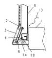
従来この装置は図3,図4に示すように、加熱室1の開口部に位置する扉2の組立構成は、キーボード3、制御基板4からなる操作パネルユニット5を扉2に取付ビス6にて固定した後、矢印A7で周囲に電波チョーク溝を有するシールドバン8、矢印B9でシールドバン取付ビス10、矢印C11でチョークカバー12を順次取り付ける構成である。
【0003】
従って不良が発生した時の操作パネルユニット5のサービス時は組立時とは逆の分解が必要となる。また、加熱室1の内部は被加熱物から発生する蒸気,熱気13が加熱室1とシールドバン8の隙間から矢印D14方向へ流入し易い構造となっている。
【0004】
【発明が解決しようとする課題】
この従来の構成の場合、加熱室1側からの操作パネルユニット5を装着するため、嵌合部に空間,隙間が発生するため加熱室1からの蒸気,熱気13が操作パネルユニット5に流入し、微少電流,電圧で制御している電気回路が漏電,絶縁不良となり品質性能に課題が生じた。また、操作パネルユニット5のサービス時には、電波遮蔽性能に影響のあるシールドバン8等を取り外さないと部品交換が出来ないため、スピーディで信頼性の高いサービスができ難かった。また、近年使用済み製品のリサイクル時に管理対象材質を多く含む制御回路部材の分解,分別を容易にすることも大きな社会的要望となってきている。
【0005】
そして操作パネルユニット5表面は毎回使用時に手に触れるため清掃し易く衛生的であることが必要条件である。
【0006】
【課題を解決するための手段】
本発明は上記課題を解決するため、加熱室の開口面に対向し、高周波の漏洩を防止するシールドバン、前記加熱室を透視するスクリーンガラス、高周波発生装置などを制御,操作,表示する操作パネルユニットを搭載した開閉自在な扉を備え、上記シールドバンと操作パネルユニットとの間には、扉と一体形成され、前記加熱室からの蒸気、熱気が前記操作パネルユニット側に流入しないようにする遮蔽壁を設けるとともに、前記操作パネルユニットはその上部に設けた凸部で前記スクリーンガラスを挟持して前記扉に挿入固定し、下部を当該扉の下部側面に装着しビス等で係止して着脱可能としたものである。
【0007】
【発明の実施の形態】
本発明の高周波加熱装置は、被加熱物を収納して加熱する加熱室と、この加熱室に高周波を供給する高周波発生装置と、前記加熱室の開口面に対向し、高周波の漏洩を防止するシールドバン、前記加熱室を透視するスクリーンガラス、高周波発生装置などを制御,操作,表示する操作パネルユニットを搭載した開閉自在な扉を備え、上記シールドバンと操作パネルユニットとの間には、扉と一体形成され、前記加熱室からの蒸気、熱気が前記操作パネルユニット側に流入しないようにする遮蔽壁を設けるとともに、前記操作パネルユニットはその上部に設けた凸部で前記スクリーンガラスを挟持して前記扉に挿入固定し、下部を当該扉の下部側面に装着しビス等で係止して着脱可能とした構成としてある。
被加熱物を収納して加熱する加熱室と、この加熱室に高周波を供給する高周波発生装置と、前記加熱室の開口面に対向し、高周波の漏洩を防止するシールドバン、前記加熱室を透視するスクリーンガラス、高周波発生装置などを制御,操作,表示する操作パネルユニットを搭載した開閉自在な扉を備え、上記操作パネルユニットは前記扉の表面側から脱着可能としたものである。
【0008】
これにより、作パネルユニットは前記扉の表面側から脱着できるとともに、加熱室側からの蒸気,熱気が操作パネルユニットに流入することを防ぎ品質トラブルの解消と、操作パネルユニットのサービス時の信頼性の向上及び、使用済み製品のリサイクル時の分解,分別を容易にするものである。
【0009】
また、操作パネルユニットは上部をスクリーンガラスを挟持して扉に挿入固定し、下部を上記扉の下部側面にビス等で係止してあるから、操作パネルユニットの表面を清掃し易いように凹凸のないフラット構造にし、清掃し易く衛生的な構成となる。
【0010】
【実施例】
(実施例1)
以下本発明の実施例1を図面に基づいて説明する。図1(a)は実施例1の高周波加熱装置の外観図であり、(b)は同要部の拡大詳細図である。また、図2は図1(b)に相当する部分での組立順序を示した図である。
【0011】
図において、加熱室1の底部に内蔵した高周波発生装置15から加熱室1に高周波が照射される。被加熱物が収納されている加熱室1の開口部にはヒンジ16を支点に回動自在な扉2Aが装着されている。扉2Aは加熱室1側には扉2Aに取付ビス10にて固定され、周囲をチョーク溝を有し、加熱室1内に照射された高周波が製品外に漏洩することを防止するシールドバン8と、シールドバン8のチョーク溝を覆うチョークカバー12が配置されている。そして扉2Aの表面側には、中央部には加熱室1を透視するためのスクリーンガラス17、下部には運転情報を入力するキーボード3、及び高周波発生装置15をコントロールする制御基板4からなる操作パネルユニット5Aが構成されている。操作パネルユニット5Aはキーボード3、制御基板4を内蔵し、表面側にフタA18裏面側にフタB19を設け、全体としてパッケージ化され、ユニットとして扉2Aへの装着,脱着を可能に構成されている。
【0012】
操作パネルユニット5Aの扉2Aへの組み付け構成を示した図2に基づいて説明する。操作パネルユニット5Aの上部に設けた凸部20を扉2A側に位置するスクリーンガラス17を挟持しながら扉2Aに設けた凹部21に矢印22のように挿入する、またこの動きと連動して操作パネルユニット5Aの下部側面に設けたボス23を矢印24のように扉2A下部側面に装着し、取付ビス25にて操作パネルユニット5Aを扉2Aに係止する構成である。
【0013】
また、操作パネルユニット5Aとシールドバン8の間には加熱室1からの蒸気,熱気13が流入しないように扉2Aと一体形成された遮蔽壁26を設け、微少電流,電圧で制御している電気回路が漏電,絶縁不良等の品質トラブルを解消している。
【0014】
【発明の効果】
以上のように、本発明によれば、加熱室側からの蒸気,熱気が操作パネルユニットに流入することを防ぎ品質トラブルの解消と、操作パネルユニットのサービス時の信頼性の向上及び、使用済み製品のリサイクル時の分解,分別を容易にする。
【0015】
また、操作パネルユニットは扉に装着時、上部をスクリーンガラスを挟持して扉に挿入固定し、下部を扉の下部側面に取付ビスで係止したことにより、操作パネルユニットの表面を清掃し易いように凹凸のないフラット構造にし、清掃し易く衛生的な製品を提供する。
【図面の簡単な説明】
【図1】 (a)本発明の実施例1の高周波加熱装置の外観図
(b)本発明の実施例1の高周波加熱装置の要部断面図
【図2】 本発明の高周波加熱装置の組立順序を示す図
【図3】 従来の構成図
【図4】 従来の構成の組立順序を示す図
【符号の説明】
1 加熱室
2A 扉
3 キーボード
4 制御基板
5A 操作パネルユニット
8 シールドバン
15 高周波発生装置
17 スクリーンガラス
26 遮蔽壁[0001]
BACKGROUND OF THE INVENTION
The present invention relates to a high-frequency heating device such as a microwave oven.
[0002]
[Prior art]
Conventionally, as shown in FIGS. 3 and 4, this apparatus has an assembly configuration of the
[0003]
Accordingly, when the
[0004]
[Problems to be solved by the invention]
In the case of this conventional configuration, since the
[0005]
And since the surface of the
[0006]
[Means for Solving the Problems]
In order to solve the above-mentioned problems, the present invention provides an operation panel that controls, operates, and displays a shield van that faces the opening surface of the heating chamber and prevents high-frequency leakage, a screen glass that sees through the heating chamber, and a high-frequency generator. An openable / closable door equipped with the unit is provided,and is formed integrally with the door between the shield van and the operation panel unit so that steam and hot air from the heating chamber do not flow into the operation panel unit side. In addition to providing a shielding wall, the operation panel unit is inserted and fixed to the door by sandwiching the screen glass with a convex portion provided on the upper part, and the lower part is attached to the lower side surface of the door and locked with a screw or the like. Detachable.
[0007]
DETAILED DESCRIPTION OF THE INVENTION
The high-frequency heating device of the present invention is a heating chamber that houses and heats an object to be heated, a high-frequency generator that supplies a high frequency to the heating chamber, and an opening surface of the heating chamber, which prevents high-frequency leakage. A shield van, a screen glass that sees through the heating chamber, and an openable door equipped with an operation panel unit that controls, operates, and displays a high-frequency generator, etc., are providedbetween the shield van and the operation panel unit. And a shielding wall that prevents steam and hot air from the heating chamber from flowing into the operation panel unit side, and the operation panel unit sandwiches the screen glass with a convex portion provided on the upper portion thereof. The door is inserted and fixed to the door, and the lower part is attached to the lower side surface of the door and locked with a screw or the like to be detachable.
A heating chamber that houses and heats an object to be heated, a high-frequency generator that supplies a high frequency to the heating chamber, a shield van that faces the opening surface of the heating chamber and prevents high-frequency leakage, and the heating chamber are seen through And an openable / closable door equipped with an operation panel unit for controlling, operating, and displaying a screen glass, a high-frequency generator, and the like. The operation panel unit is removable from the surface side of the door.
[0008]
As a result, the panel unit can be detached from the front side of the door, and steam and hot air from the heating chamber sidecan be prevented from flowing into the operation panel unit, eliminating quality problems and reliability during service of the operation panel unit. And facilitate the disassembly and separation of used products during recycling.
[0009]
Further,since the operation panel unit upper insert is fixed to the door by holding the screen glass,are then engaging with screws or the like the lower the bottom side of thedoor, so as to facilitate cleaning the surface of the operation panel unit irregularities the free flat structure,the cleaning and easy hygienic construction.
[0010]
【Example】
Example 1
Embodiment 1 of the present invention will be described below with reference to the drawings. Fig.1 (a) is an external view of the high frequency heating apparatus of Example 1, (b) is an enlarged detail drawing of the principal part. FIG. 2 is a view showing an assembly order in a portion corresponding to FIG.
[0011]
In the figure, a high frequency is irradiated to the heating chamber 1 from a
[0012]
It will be described with reference to FIG.2 showing the assembled structure of the door 2A of the operation panel unit 5A. Insert as shown by the
[0013]
In addition, a
[0014]
【The invention's effect】
As described above,according to the present invention, steam and hot air from theheating chamber side are prevented from flowing into the operation panel unit, quality troubles are solved, reliability of the operation panel unit is improved, and used. Facilitates disassembly and separation during product recycling.
[0015]
In addition, when the operation panel unit is mounted on the door, the upper part is inserted and fixed to the door with the screen glass sandwiched, and the lower part is locked to the lower side of the door with a mounting screw, making it easy to clean the surface of the operation panel unit. The product has a flat structure with no unevenness and provides hygienic products that are easy to clean.
[Brief description of the drawings]
1A is an external view of a high-frequency heating device according to a first embodiment of the present invention. FIG. 1B is a cross-sectional view of a main part of the high-frequency heating device according to the first embodiment of the present invention. Diagram showing the order [Fig. 3] Fig. 4 shows the conventional configuration diagram [Fig. 4] Fig. 3 shows the assembly sequence of the conventional configuration [Explanation of symbols]
DESCRIPTION OF SYMBOLS 1 Heating
Claims (1)
Translated fromJapanesePriority Applications (1)
| Application Number | Priority Date | Filing Date | Title |
|---|---|---|---|
| JP17106498AJP3932676B2 (en) | 1998-06-18 | 1998-06-18 | High frequency heating device |
Applications Claiming Priority (1)
| Application Number | Priority Date | Filing Date | Title |
|---|---|---|---|
| JP17106498AJP3932676B2 (en) | 1998-06-18 | 1998-06-18 | High frequency heating device |
Publications (2)
| Publication Number | Publication Date |
|---|---|
| JP2000002432A JP2000002432A (en) | 2000-01-07 |
| JP3932676B2true JP3932676B2 (en) | 2007-06-20 |
Family
ID=15916391
Family Applications (1)
| Application Number | Title | Priority Date | Filing Date |
|---|---|---|---|
| JP17106498AExpired - Fee RelatedJP3932676B2 (en) | 1998-06-18 | 1998-06-18 | High frequency heating device |
Country Status (1)
| Country | Link |
|---|---|
| JP (1) | JP3932676B2 (en) |
Families Citing this family (6)
| Publication number | Priority date | Publication date | Assignee | Title |
|---|---|---|---|---|
| CN1318806C (en)* | 2004-05-06 | 2007-05-30 | 松下电器产业株式会社 | High frequency heating cooking utensil |
| JP4602172B2 (en)* | 2005-06-24 | 2010-12-22 | 株式会社東芝 | Cooker |
| DE102006001248A1 (en)* | 2006-01-10 | 2007-07-12 | BSH Bosch und Siemens Hausgeräte GmbH | User control module for a domestic appliance is integrated in the access door of the appliance, especially an oven,in a cavity created in the door frame |
| KR100820835B1 (en) | 2006-09-05 | 2008-04-11 | 엘지전자 주식회사 | Cooker |
| CN102221224A (en)* | 2010-04-15 | 2011-10-19 | 乐金电子(天津)电器有限公司 | Novel microwave oven door |
| CN104075354B (en)* | 2014-07-17 | 2018-07-06 | 广东美的厨房电器制造有限公司 | The touch display screen component of micro-wave oven |
- 1998
- 1998-06-18JPJP17106498Apatent/JP3932676B2/ennot_activeExpired - Fee Related
Also Published As
| Publication number | Publication date |
|---|---|
| JP2000002432A (en) | 2000-01-07 |
Similar Documents
| Publication | Publication Date | Title |
|---|---|---|
| US3846608A (en) | High temperature resistant door seal for a microwave oven | |
| US7348527B2 (en) | Microwave oven having a door ventilation system | |
| JP3932676B2 (en) | High frequency heating device | |
| CA1111505A (en) | Microwave oven having a radiation leak-proof drawer type door | |
| EP2816290B1 (en) | Heating cooker | |
| WO2007055132A1 (en) | Cooking device | |
| JP2004146341A (en) | Door of microwave oven | |
| EP1503613B1 (en) | Microwave oven | |
| EP1377131A2 (en) | Door for microwave oven | |
| JPH09229377A (en) | microwave | |
| JP2022039641A (en) | Heating cooker | |
| JP3757363B2 (en) | Cooker | |
| KR20230092658A (en) | Cooking apparatus | |
| JP6876171B2 (en) | Cooker | |
| JP5610914B2 (en) | Induction heating cooker | |
| KR100200798B1 (en) | Microwave | |
| JP3931431B2 (en) | High frequency heating device | |
| KR100272226B1 (en) | a mounting structure of a door for microwave oven | |
| KR101331189B1 (en) | Cooking Device | |
| KR100301257B1 (en) | Microwave Door | |
| JP2010117108A (en) | High-frequency heating device with steam generating function | |
| KR20080063430A (en) | Oven door | |
| KR19990018409U (en) | Microwave Door Structure | |
| KR101004485B1 (en) | Cooker | |
| KR20040087219A (en) | A microwave oven |
Legal Events
| Date | Code | Title | Description |
|---|---|---|---|
| A621 | Written request for application examination | Free format text:JAPANESE INTERMEDIATE CODE: A621 Effective date:20050616 | |
| RD01 | Notification of change of attorney | Free format text:JAPANESE INTERMEDIATE CODE: A7421 Effective date:20050621 | |
| A131 | Notification of reasons for refusal | Free format text:JAPANESE INTERMEDIATE CODE: A131 Effective date:20061128 | |
| A521 | Written amendment | Free format text:JAPANESE INTERMEDIATE CODE: A523 Effective date:20070125 | |
| TRDD | Decision of grant or rejection written | ||
| A01 | Written decision to grant a patent or to grant a registration (utility model) | Free format text:JAPANESE INTERMEDIATE CODE: A01 Effective date:20070227 | |
| A61 | First payment of annual fees (during grant procedure) | Free format text:JAPANESE INTERMEDIATE CODE: A61 Effective date:20070312 | |
| FPAY | Renewal fee payment (event date is renewal date of database) | Free format text:PAYMENT UNTIL: 20100330 Year of fee payment:3 | |
| FPAY | Renewal fee payment (event date is renewal date of database) | Free format text:PAYMENT UNTIL: 20110330 Year of fee payment:4 | |
| FPAY | Renewal fee payment (event date is renewal date of database) | Free format text:PAYMENT UNTIL: 20110330 Year of fee payment:4 | |
| FPAY | Renewal fee payment (event date is renewal date of database) | Free format text:PAYMENT UNTIL: 20120330 Year of fee payment:5 | |
| FPAY | Renewal fee payment (event date is renewal date of database) | Free format text:PAYMENT UNTIL: 20130330 Year of fee payment:6 | |
| FPAY | Renewal fee payment (event date is renewal date of database) | Free format text:PAYMENT UNTIL: 20130330 Year of fee payment:6 | |
| FPAY | Renewal fee payment (event date is renewal date of database) | Free format text:PAYMENT UNTIL: 20140330 Year of fee payment:7 | |
| LAPS | Cancellation because of no payment of annual fees |