JP3931990B2 - Sliding device - Google Patents
Sliding deviceDownload PDFInfo
- Publication number
- JP3931990B2 JP3931990B2JP2005130573AJP2005130573AJP3931990B2JP 3931990 B2JP3931990 B2JP 3931990B2JP 2005130573 AJP2005130573 AJP 2005130573AJP 2005130573 AJP2005130573 AJP 2005130573AJP 3931990 B2JP3931990 B2JP 3931990B2
- Authority
- JP
- Japan
- Prior art keywords
- sliding
- shoe
- swash plate
- sliding surface
- base material
- Prior art date
- Legal status (The legal status is an assumption and is not a legal conclusion. Google has not performed a legal analysis and makes no representation as to the accuracy of the status listed.)
- Expired - Fee Related
Links
Images


Classifications
- F—MECHANICAL ENGINEERING; LIGHTING; HEATING; WEAPONS; BLASTING
- F04—POSITIVE - DISPLACEMENT MACHINES FOR LIQUIDS; PUMPS FOR LIQUIDS OR ELASTIC FLUIDS
- F04B—POSITIVE-DISPLACEMENT MACHINES FOR LIQUIDS; PUMPS
- F04B27/00—Multi-cylinder pumps specially adapted for elastic fluids and characterised by number or arrangement of cylinders
- F04B27/08—Multi-cylinder pumps specially adapted for elastic fluids and characterised by number or arrangement of cylinders having cylinders coaxial with, or parallel or inclined to, main shaft axis
- F04B27/0873—Component parts, e.g. sealings; Manufacturing or assembly thereof
- F04B27/0878—Pistons
- F04B27/0886—Piston shoes
- F—MECHANICAL ENGINEERING; LIGHTING; HEATING; WEAPONS; BLASTING
- F04—POSITIVE - DISPLACEMENT MACHINES FOR LIQUIDS; PUMPS FOR LIQUIDS OR ELASTIC FLUIDS
- F04B—POSITIVE-DISPLACEMENT MACHINES FOR LIQUIDS; PUMPS
- F04B27/00—Multi-cylinder pumps specially adapted for elastic fluids and characterised by number or arrangement of cylinders
- F04B27/08—Multi-cylinder pumps specially adapted for elastic fluids and characterised by number or arrangement of cylinders having cylinders coaxial with, or parallel or inclined to, main shaft axis
- F04B27/0804—Multi-cylinder pumps specially adapted for elastic fluids and characterised by number or arrangement of cylinders having cylinders coaxial with, or parallel or inclined to, main shaft axis having rotary cylinder block
- F04B27/0821—Multi-cylinder pumps specially adapted for elastic fluids and characterised by number or arrangement of cylinders having cylinders coaxial with, or parallel or inclined to, main shaft axis having rotary cylinder block component parts, details, e.g. valves, sealings, lubrication
- F04B27/086—Multi-cylinder pumps specially adapted for elastic fluids and characterised by number or arrangement of cylinders having cylinders coaxial with, or parallel or inclined to, main shaft axis having rotary cylinder block component parts, details, e.g. valves, sealings, lubrication swash plate
- F—MECHANICAL ENGINEERING; LIGHTING; HEATING; WEAPONS; BLASTING
- F04—POSITIVE - DISPLACEMENT MACHINES FOR LIQUIDS; PUMPS FOR LIQUIDS OR ELASTIC FLUIDS
- F04B—POSITIVE-DISPLACEMENT MACHINES FOR LIQUIDS; PUMPS
- F04B39/00—Component parts, details, or accessories, of pumps or pumping systems specially adapted for elastic fluids, not otherwise provided for in, or of interest apart from, groups F04B25/00 - F04B37/00
- F—MECHANICAL ENGINEERING; LIGHTING; HEATING; WEAPONS; BLASTING
- F16—ENGINEERING ELEMENTS AND UNITS; GENERAL MEASURES FOR PRODUCING AND MAINTAINING EFFECTIVE FUNCTIONING OF MACHINES OR INSTALLATIONS; THERMAL INSULATION IN GENERAL
- F16C—SHAFTS; FLEXIBLE SHAFTS; ELEMENTS OR CRANKSHAFT MECHANISMS; ROTARY BODIES OTHER THAN GEARING ELEMENTS; BEARINGS
- F16C33/00—Parts of bearings; Special methods for making bearings or parts thereof
- F16C33/02—Parts of sliding-contact bearings
- F16C33/04—Brasses; Bushes; Linings
- F16C33/06—Sliding surface mainly made of metal
- F16C33/10—Construction relative to lubrication
- F16C33/1025—Construction relative to lubrication with liquid, e.g. oil, as lubricant
- F16C33/106—Details of distribution or circulation inside the bearings, e.g. details of the bearing surfaces to affect flow or pressure of the liquid
- F—MECHANICAL ENGINEERING; LIGHTING; HEATING; WEAPONS; BLASTING
- F16—ENGINEERING ELEMENTS AND UNITS; GENERAL MEASURES FOR PRODUCING AND MAINTAINING EFFECTIVE FUNCTIONING OF MACHINES OR INSTALLATIONS; THERMAL INSULATION IN GENERAL
- F16C—SHAFTS; FLEXIBLE SHAFTS; ELEMENTS OR CRANKSHAFT MECHANISMS; ROTARY BODIES OTHER THAN GEARING ELEMENTS; BEARINGS
- F16C33/00—Parts of bearings; Special methods for making bearings or parts thereof
- F16C33/02—Parts of sliding-contact bearings
- F16C33/04—Brasses; Bushes; Linings
- F16C33/06—Sliding surface mainly made of metal
- F16C33/14—Special methods of manufacture; Running-in
- F—MECHANICAL ENGINEERING; LIGHTING; HEATING; WEAPONS; BLASTING
- F05—INDEXING SCHEMES RELATING TO ENGINES OR PUMPS IN VARIOUS SUBCLASSES OF CLASSES F01-F04
- F05C—INDEXING SCHEME RELATING TO MATERIALS, MATERIAL PROPERTIES OR MATERIAL CHARACTERISTICS FOR MACHINES, ENGINES OR PUMPS OTHER THAN NON-POSITIVE-DISPLACEMENT MACHINES OR ENGINES
- F05C2201/00—Metals
- F05C2201/02—Light metals
- F05C2201/021—Aluminium
- F—MECHANICAL ENGINEERING; LIGHTING; HEATING; WEAPONS; BLASTING
- F05—INDEXING SCHEMES RELATING TO ENGINES OR PUMPS IN VARIOUS SUBCLASSES OF CLASSES F01-F04
- F05C—INDEXING SCHEME RELATING TO MATERIALS, MATERIAL PROPERTIES OR MATERIAL CHARACTERISTICS FOR MACHINES, ENGINES OR PUMPS OTHER THAN NON-POSITIVE-DISPLACEMENT MACHINES OR ENGINES
- F05C2201/00—Metals
- F05C2201/04—Heavy metals
- F05C2201/0403—Refractory metals, e.g. V, W
- F05C2201/0412—Titanium
- F—MECHANICAL ENGINEERING; LIGHTING; HEATING; WEAPONS; BLASTING
- F05—INDEXING SCHEMES RELATING TO ENGINES OR PUMPS IN VARIOUS SUBCLASSES OF CLASSES F01-F04
- F05C—INDEXING SCHEME RELATING TO MATERIALS, MATERIAL PROPERTIES OR MATERIAL CHARACTERISTICS FOR MACHINES, ENGINES OR PUMPS OTHER THAN NON-POSITIVE-DISPLACEMENT MACHINES OR ENGINES
- F05C2201/00—Metals
- F05C2201/04—Heavy metals
- F05C2201/0433—Iron group; Ferrous alloys, e.g. steel
- F—MECHANICAL ENGINEERING; LIGHTING; HEATING; WEAPONS; BLASTING
- F05—INDEXING SCHEMES RELATING TO ENGINES OR PUMPS IN VARIOUS SUBCLASSES OF CLASSES F01-F04
- F05C—INDEXING SCHEME RELATING TO MATERIALS, MATERIAL PROPERTIES OR MATERIAL CHARACTERISTICS FOR MACHINES, ENGINES OR PUMPS OTHER THAN NON-POSITIVE-DISPLACEMENT MACHINES OR ENGINES
- F05C2201/00—Metals
- F05C2201/04—Heavy metals
- F05C2201/0469—Other heavy metals
- F05C2201/0475—Copper or alloys thereof
- F—MECHANICAL ENGINEERING; LIGHTING; HEATING; WEAPONS; BLASTING
- F05—INDEXING SCHEMES RELATING TO ENGINES OR PUMPS IN VARIOUS SUBCLASSES OF CLASSES F01-F04
- F05C—INDEXING SCHEME RELATING TO MATERIALS, MATERIAL PROPERTIES OR MATERIAL CHARACTERISTICS FOR MACHINES, ENGINES OR PUMPS OTHER THAN NON-POSITIVE-DISPLACEMENT MACHINES OR ENGINES
- F05C2253/00—Other material characteristics; Treatment of material
- F05C2253/12—Coating
- Y—GENERAL TAGGING OF NEW TECHNOLOGICAL DEVELOPMENTS; GENERAL TAGGING OF CROSS-SECTIONAL TECHNOLOGIES SPANNING OVER SEVERAL SECTIONS OF THE IPC; TECHNICAL SUBJECTS COVERED BY FORMER USPC CROSS-REFERENCE ART COLLECTIONS [XRACs] AND DIGESTS
- Y10—TECHNICAL SUBJECTS COVERED BY FORMER USPC
- Y10T—TECHNICAL SUBJECTS COVERED BY FORMER US CLASSIFICATION
- Y10T74/00—Machine element or mechanism
- Y10T74/18—Mechanical movements
- Y10T74/18056—Rotary to or from reciprocating or oscillating
- Y10T74/18296—Cam and slide
- Y10T74/18336—Wabbler type
Landscapes
- Engineering & Computer Science (AREA)
- General Engineering & Computer Science (AREA)
- Mechanical Engineering (AREA)
- Chemical & Material Sciences (AREA)
- Oil, Petroleum & Natural Gas (AREA)
- Manufacturing & Machinery (AREA)
- Compressors, Vaccum Pumps And Other Relevant Systems (AREA)
- Compressor (AREA)
- Sliding-Contact Bearings (AREA)
Description
Translated fromJapanese本発明は摺動装置に関し、より詳しくは、例えば斜板式コンプレッサにおける斜板とシューとして好適な摺動装置に関する。The present invention relates to a sliding device, and more particularly to a sliding device suitable as a swash plate and a shoe in a swash plate compressor, for example.
従来、斜板式コンプレッサとして、回転自在に設けた斜板と、この斜板と摺動する摺動面を有するシューとを備えたものは知られている(例えば特許文献1、特許文献2)。
ところで、上述した従来の斜板式コンプレッサは、最近では高速で高荷重の条件下で、しかも潤滑油量が少ない条件において使用されるようになっている。このように、最近では斜板式コンプレッサの作動条件が益々苛酷なものとなっており、そのために斜板やシューの摩耗が激しくなり、しかもそれらの焼付きが生じやすいという問題が生じている。
さらに、従来からシューの摺動特性を向上させるために、シューの摺動面に表面処理を施したり、改質したりといった処理を行っているが、このような処理を行うことによりシューの製造コストが高くなるという欠点があった。By the way, the above-described conventional swash plate compressor has recently been used under conditions of high speed and high load and a small amount of lubricating oil. Thus, recently, the operating conditions of swash plate compressors have become increasingly severe, and as a result, the swash plate and shoes wear more seriously, and there is a problem that they are likely to be seized.
Furthermore, in order to improve the sliding characteristics of the shoe, the surface of the sliding surface of the shoe has been subjected to surface treatment and modification. There was a drawback that the cost was high.
上述した事情に鑑み、請求項1に記載した本発明は、回転軸に連動して回転され、かつ両端面の少なくとも一方に平坦な第1摺動面を有する斜板と、上記斜板の第1摺動面と摺動する第2摺動面を有するシューとを備えた摺動装置において、
上記シューの材料として鉄系材料を用いるとともに、このシューの第2摺動面に多数の微小な環状膨出部からなる焼入れ部を形成し、上記各環状膨出部の半径方向内方は潤滑油を貯溜する凹部となっており、また、各環状膨出部の半径方向外方には潤滑油が流通可能な網目状凹部からなる潤滑油通路が形成されており、さらに、上記斜板の材料として下記a〜eのいずれかを用いた摺動装置を提供するものである。
(a)高力黄銅
(b)鉄系基材を銅合金で被覆したもの
(c)アルミシリコン合金
(d)鉄系基材をアルミシリコン合金で被覆したもの
(e)鉄系基材
また、請求項2に記載した本発明は、回転軸に連動して回転され、かつ両端面の少なくとも一方に平坦な第1摺動面を有する斜板と、上記斜板の第1摺動面と摺動する第2摺動面を有するシューとを備えた摺動装置において、
上記シューの材料としてアルミシリコン合金を用いるとともに、このシューの第2摺動面にNi−P系の硬質メッキを施した後に、多数の微小な環状膨出部からなる焼入れ部を形成し、上記各環状膨出部の半径方向内方は潤滑油を貯溜する凹部となっており、また、各環状膨出部の半径方向外方には潤滑油が流通可能な網目状凹部からなる潤滑油通路が形成されており、さらに、上記斜板の材料として下記a〜eのいずれかを用いたことを特徴とする摺動装置を提供するものである。
(a)高力黄銅
(b)鉄系基材を銅合金で被覆したもの
(c)アルミシリコン合金
(d)鉄系基材をアルミシリコン合金で被覆したもの
(e)鉄系基材
また、請求項3に記載した本発明は、回転軸に連動して回転され、かつ両端面の少なくとも一方に平坦な第1摺動面を有する斜板と、上記斜板の第1摺動面と摺動する第2摺動面を有するシューとを備えた摺動装置において、
上記シューの材料として銅合金を用いるとともに、このシューの第2摺動面にNi−P系の硬質メッキを施した後に、多数の微小な環状膨出部からなる焼入れ部を形成し、上記各環状膨出部の半径方向内方は潤滑油を貯溜する凹部となっており、また、各環状膨出部の半径方向外方には潤滑油が流通可能な網目状凹部からなる潤滑油通路が形成されており、さらに、上記斜板の材料として下記a〜eのいずれかを用いたことを特徴とする摺動装置を提供するものである。
(a)高力黄銅
(b)鉄系基材を銅合金で被覆したもの
(c)アルミシリコン合金
(d)鉄系基材をアルミシリコン合金で被覆したもの
(e)鉄系基材
さらに、請求項4に記載した本発明は、回転軸に連動して回転され、かつ両端面の少なくとも一方に平坦な第1摺動面を有する斜板と、上記斜板の第1摺動面と摺動する第2摺動面を有するシューとを備えた摺動装置において、
上記シューの材料として純チタン又はチタン合金を用いるとともに、このシューの第2摺動面に多数の微小な環状膨出部からなる焼入れ部を形成し、上記各環状膨出部の半径方向内方は潤滑油を貯溜する凹部となっており、また、各環状膨出部の半径方向外方には潤滑油が流通可能な網目状凹部からなる潤滑油通路が形成されており、さらに、上記斜板の材料として下記a〜eのいずれかを用いた摺動装置を提供するものである。
(a)高力黄銅
(b)鉄系基材を銅合金で被覆したもの
(c)アルミシリコン合金
(d)鉄系基材をアルミシリコン合金で被覆したもの
(e)鉄系基材In view of the above-described circumstances, the present invention described in claim 1 is a swash plate that is rotated in conjunction with a rotation shaft and has a flat first sliding surface on at least one of both end surfaces, and a first swash plate. In a sliding device including a sliding surface and a shoe having a second sliding surface that slides,
An iron-based material is used as a material for the shoe, and a hardened portion madeup of a large number of minute annular bulges isformed on the second sliding surface of the shoe, and theradially inner portions of the annular bulges are lubricated. A recess for storing oil is formed, and a lubricant passage including a mesh-like recess through which the lubricant can flow is formed radially outward of each annular bulge . The present invention provides a sliding device using any of the following a to e as a material.
(A) High-strength brass (b) Iron-based substrate coated with copper alloy (c) Aluminum-silicon alloy (d) Iron-based substrate coated with aluminum-silicon alloy (e) Iron-based substrate According to a second aspect of the present invention, there is provided a swash plate that is rotated in conjunction with a rotation shaft and has a flat first sliding surface on at least one of both end surfaces, and a sliding surface that slides on the first sliding surface of the swash plate. In a sliding device comprising a shoe having a second sliding surface that moves,
An aluminum silicon alloy is used as the material for the shoe, and after the Ni-P hard plating is applied to the second sliding surface of the shoe, a hardened portion including a large number of minute annular bulges isformed, A radially inward portion of each annular bulging portion is a concave portion for storing lubricating oil, and a lubricating oil passage formed by a mesh-shaped concave portion through which the lubricating oil can flow is radially outward of each annular bulging portion. Further, the present invention provides a sliding device characterized in that any one of the following a to e is used as a material for the swash plate.
(A) High-strength brass (b) Iron-based substrate coated with copper alloy (c) Aluminum-silicon alloy (d) Iron-based substrate coated with aluminum-silicon alloy (e) Iron-based substrate According to a third aspect of the present invention, there is provided a swash plate that is rotated in conjunction with a rotating shaft and has a flat first sliding surface on at least one of both end surfaces, and a sliding plate that slides on the first sliding surface of the swash plate. In a sliding device comprising a shoe having a second sliding surface that moves,
A copper alloy is used as a material for the shoe, and after the Ni-P hard plating is applied to the second sliding surface of the shoe, a quenching portion composed of a large number of minute annular bulge portions isformed, A radially inward portion of the annular bulging portion is a concave portion for storing lubricating oil, and a radially outer portion of each annular bulging portion has a lubricating oil passage formed of a mesh-shaped concave portion through which the lubricating oil can flow. Furthermore, the present invention provides a sliding device characterized in that any one of the following a to e is used as a material for the swash plate.
(A) High-strength brass (b) Iron-based substrate coated with a copper alloy (c) Aluminum-silicon alloy (d) Iron-based substrate coated with an aluminum-silicon alloy (e) Iron-based substrate According to a fourth aspect of the present invention, there is provided a swash plate that is rotated in conjunction with a rotation shaft and has a flat first sliding surface on at least one of both end surfaces, and a sliding plate that slides on the first sliding surface of the swash plate. In a sliding device comprising a shoe having a second sliding surface that moves,
Pure titanium or titanium alloy is used as a material for the shoe, and a quenching portion madeup of a large number of minute annular bulges isformed on the second sliding surface of the shoe.Is a recess for storing lubricating oil, and a lubricating oil passage made of a mesh-like recess through which the lubricating oil can flow is formed radially outward of each annular bulging portion. The present invention provides a sliding device using any one of the following a to e as a material for the plate.
(A) High-strength brass (b) Coated iron base material with copper alloy (c) Aluminum silicon alloy (d) Coated iron base material with aluminum silicon alloy (e) Iron base material
このような構成によれば、耐焼付性が良好な摺動装置を提供することができる。 According to such a configuration, a sliding device having good seizure resistance can be provided.
以下図示実施例について本発明を説明すると、図1において、摺動装置1は斜板式コンプレッサのハウジング内に設けられている。この摺動装置1は、上記ハウジング内に軸支した回転軸2に傾斜させて取り付けた斜板3と、この斜板3と摺動する複数のシュー4とから構成されている。
斜板3は円板状に形成されており、この斜板3における両方の端面は、シュー4と摺動する平坦な摺動面3A、3Aとなっている。
一方、シュー4は全体として半球状に形成されており、上記斜板3の摺動面3Aと摺動する摺動面4Aと、半球状をした半球状凸面4Bとから構成されている。The present invention will be described below with reference to the illustrated embodiment. In FIG. 1, a sliding device 1 is provided in a housing of a swash plate compressor. The sliding device 1 includes a
The
On the other hand, the
上記斜板式コンプレッサのハウジング内には、回転軸2と平行に、かつそれを囲繞して複数のピストン5を配置している。各ピストン5の一端に形成した円弧状の切欠き部5A内に2個1組のシュー4を摺動自在に保持してあり、その状態の切欠き部5Aを上記斜板3の外周部を包み込むように配置すると同時に、各組のシュー4の摺動面4Aを斜板3の摺動面3Aに当接させている。
そして、上記回転軸2が回転されると斜板3が回転して、斜板3の両端面である摺動面3Aと各組のシュー4の摺動面4Aとが摺動し、それに伴って各組のシュー4を介して各ピストン5が軸方向に進退動されるようになっている。
上述した構成は従来公知の摺動装置のものと変わるところはない。In the housing of the swash plate compressor, a plurality of
When the
The configuration described above is not different from that of a conventionally known sliding device.
しかして、本実施例のシュー4は鉄系材料であるSUJ2からなり、端面からなる概略平坦な摺動面4Aは、その中心側が外周縁よりも僅かに(2μm程度)盛り上がった中高形状となっている。これにより、摺動面4Aが上記斜板3の摺接面3Aと摺動する際には、両摺動面4A、3Aとの間に潤滑油が引き込まれやすい形状となっている。
そして、後述するように、本実施例においては、シュー4の摺動面4Aの全域にレーザを照射して焼入れするとともに、斜板3も改良することによって、両部材の摺動面3A、4Aの耐焼付性を向上させ、ひいては摺動装置1全体の耐焼付性を向上させるようにしている。Therefore, the
As will be described later, in this embodiment, the entire sliding
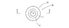
すなわち、シュー4の摺動面4Aへの焼入れとその後の加工工程を説明すると、先ず、図2〜図3に示すように、SUJ2で半球状に製造したシュー4(母材)の端面である摺動面4Aの全域に対して、多数の同一径の円6を描くようにYAGレーザを照射する。
上記各円6の直径は0.8mmに設定してあり、各円6は、摺動面4Aの全域においてピッチPが同一の縦横の平行線を引いた際の各交点の位置に中心が来るように形成している。本実施例においては、上記ピッチPは1.1mmに設定している。
本実施例においては、上記摺動面4Aに照射するYAGレーザの出力は50Wであり、これを摺動面4Aの表面に対して2mmの深さとなる位置でYAGレーザの焦点が結ばれるように集光レンズを調整して、したがって摺動面4Aの表面に対してはデフォーカスした状態でYAGレーザを照射するようにしている。That is, the quenching of the
The diameter of each
In this embodiment, the output of the YAG laser irradiating the sliding
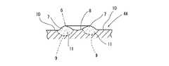
このようにレーザが照射された摺動面4Aにおける各円6の箇所は図4および図5に示すように環状に膨出して環状膨出部7となり、この環状膨出部7の半径方向の隣接内方側に、下方側が窄むテ―パ状の凹部8が形成されている。つまり、上記各円6を形成するようにレーザを摺動面4Aに照射することで、レーザが照射された円6の箇所にクレーター状の環状膨出部7が形成される。環状膨出部7の高さおよび凹部8の深さは概ね1〜3μm程度となっている。さらに、各環状膨出部7の半径方向外方側には、相互に連通し、かつ摺動面4Aの外周部まで到達する網目状凹部10が形成されている。
各環状膨出部7とその深さ方向の内方側の箇所11(破線9よりも上方側の箇所)は、シュー4の母材の硬度であるHv750に対してHv100程度硬度が増大して焼入れ処理がなされている。
他方、摺動面4Aにおける各環状膨出部7の半径方向内方側および環状膨出部7の外方の箇所(凹部8および網目状凹部10の箇所)は焼きなまされて非焼入れ部となっており、その部分は母材よりも硬度がHv100程度低下している。As shown in FIGS. 4 and 5, the locations of the
Each annular
On the other hand, the radially inward side of each annular bulging
本実施例においては、シュー4の摺動面4Aに対して上述したように多数の円6を描くようにレーザを照射することにより、先ず多数の微小な環状膨出部7および凹部8と網目状凹部10を形成する。
そして、その後にラップ加工によって一旦上記摺動面4Aにおける全ての環状膨出部7を削除して摺動面4Aを平滑な面とし、その後から摺動面4Aに対してバフ加工を施して加工が終了する。
このようにして加工が終了した後には、図6に示すように、摺動面4Aの全域にわたって上記レーザを照射した各円6の箇所(上記環状膨出部7の箇所)に上記環状膨出部7と同様の環状膨出部7’が形成されるとともに、各環状膨出部7’の半径方向内方に上記凹部8と同様の凹部8’が形成される。さらに、各環状膨出部7’の半径方向外方には潤滑油が流通可能な網目状凹部からなる潤滑油通路10’が形成される。
これは、当初の環状膨出部7がラップ加工により削除され、その後にバフ加工されることで、環状膨出部7の深さ方向の内方側の箇所11の硬度がその周辺部分の硬度よりも高くなっているため、硬度が高い部分が環状に残存することで上記環状膨出部7’、凹部8’および潤滑油通路10’が形成されるものである。In the present embodiment, by irradiating the sliding
After that, all the annular bulging
After the processing is completed in this manner, as shown in FIG. 6, the annular bulge is formed at each circle 6 (the annular bulging portion 7) irradiated with the laser over the entire
This is because the initial annular bulging
本実施例においては、このようにして形成された多数の環状膨出部8’によって焼入れ部が形成されている。また、各凹部8’は潤滑油を貯溜する貯溜部として機能するようになっており、また、潤滑油通路10’内は潤滑油が流通できるようになっている。
図6に示すように、各環状膨出部7’の高さh(凹部8’の深さ)は0.05〜0.3μm、断面の最大幅W(裾部の半径方向寸法)は約0.3mmとなっている。また各環状膨出部7’の山頂部の直径D1は0.8mmとなっている。環状膨出部7’の外周縁の直径D2は、1.1mm程度となっており、また環状膨出部7’の内周縁の直径D3は0.5mm程度となっている。
このように本実施例においては、鉄系材料であるSUJ2を母材(基材)としたシュー4において、摺動面4Aに上述したようなレーザ焼入れとその後のラップ加工とバフ加工を施している。
このように構成したシュー4に対して、本実施例では、斜板3に用いる材料としての基材とその表面処理について次のように構成している。つまり、斜板3の基材として高力黄銅を用いており、斜板3の摺動面3Aである表面には、メッキなどの特別な表面処理はしていない。In the present embodiment, a quenching portion is formed by a large number of annular bulging
As shown in FIG. 6, the height h (depth of the
As described above, in this embodiment, the
In contrast to the
次に、図7は上述した本実施例の摺動装置1と従来技術のシューを用いた摺動装置について行った耐焼付性の試験結果を示したものである。
この図7において、従来技術のシューは、その摺動面にレーザ焼入れをせず、該摺動面が平坦面となっているものである。なお、従来技術のシューも、相手材としての斜板は上記実施例と同じ黄銅材からなるものを用いた。
また、耐焼付性の試験条件は次のとおりである。
(試験条件)
斜板回転数:1000rpmずつ1分ごとに9ステップ増加:最大回転数9000rpm(周速38m/s)
面圧:予荷重2.7MPaで2.7MPaずつ1分毎に増加:焼付きに至るまで
オイルミスト量:0.05〜0.25g/min ノズル位置固定
オイル:冷凍機油
焼付き条件:軸トルク4.0N・mオーバー
つまり、シュー4の摺動面を上記斜板3に圧接させた状態で、該斜板3の回転数を上記条件で増大させる。他方、シュー4を斜板3へ圧接させる際の面圧を上記条件で増大させて、斜板3に加わる軸トルクが4.0N・mを超えた時に焼付きに至ったと判定した。これは従来技術についても同様である。Next, FIG. 7 shows the seizure resistance test results of the above-described sliding device 1 of the present embodiment and the sliding device using the conventional shoe.
In FIG. 7, the conventional shoe does not undergo laser hardening on the sliding surface, and the sliding surface is a flat surface. In the shoe of the prior art, the swash plate as the counterpart material was made of the same brass material as in the above embodiment.
The test conditions for seizure resistance are as follows.
(Test conditions)
Swash plate rotation speed: 1000 rpm increments by 9 steps per minute: Maximum rotation speed 9000 rpm (circumferential speed 38 m / s)
Surface pressure: Increased by 2.7 MPa in 1 minute increments with preload of 2.7 MPa: Until seizure Oil mist amount: 0.05 to 0.25 g / min Nozzle position fixed Oil: Refrigerating machine oil Seizure condition: Shaft torque 4.0 N · m over That is, with the sliding surface of the
この図7に示した試験結果から理解できるように、従来技術のシューと摺動装置の焼付荷重は5MPa以下であるのに対して、本実施例のシューと摺動装置のそれは22MPa以上となっており、本実施例のシュー4は従来のものと比較して明らかに優れた耐焼付性を備えている。
以上のように、本実施例によれば、耐焼付性に優れたシュー4および摺動装置1を提供することができる。
また、本実施例のシュー4の摺動面4Aには、上記多数の環状膨出部7’を形成するとともに、その半径方向内方に潤滑油を貯溜する凹部8’が形成されており、これら凹部8’内に潤滑油が貯溜されるようになっている。しかも、各環状膨出部7’の隣接外方位置には、網目状凹部からなる潤滑油通路10’が形成されている。そのためにシュー4の摺動面4Aの負荷容量を向上させることができ、ひいては耐摩耗性にも優れたシュー4と摺動装置1を提供することができる。As can be understood from the test results shown in FIG. 7, the seizure load of the conventional shoe and the sliding device is 5 MPa or less, whereas that of the shoe and the sliding device of this embodiment is 22 MPa or more. In addition, the
As described above, according to this embodiment, it is possible to provide the
Further, on the sliding
ところで、上述した本実施例においては、SUJ2を基材としたシュー4の摺動面4Aに、上述したようなレーザ焼入れとその後の加工を施しているが、シュー4に用いる基材とその摺動面4Aの表面処理との組合せは図8に示したものを採用することができる。
この図8において、S1は上述した本実施例のシュー4を示している。なお、上記本実施例においては、母材の摺動面4Aに対して上述したレーザ焼入れ以前に特に表面処理はしていないが、摺動面4Aにレーザを照射して焼入れを行う前に、摺動面4Aの表面全域に焼入れを施しても良いし、また、焼入れの代わりに摺動面4Aの表面全域に次のような表面処理を施しても良い。すなわち、(1)Ni−P系の硬質メッキ、(2)窒化、浸炭焼入れおよび浸炭窒化等の拡散処理を行っても良い。さらに、その他の表面処理として、(3)Sn、Sn合金、はんだ合金、銀メッキのいずれかを採用しても良いし、また、(4)リン酸Mn、リン酸Znのメッキのいずれかを採用しても良い。By the way, in the present embodiment described above, the laser quenching and subsequent processing as described above are performed on the sliding
In FIG. 8, S1 indicates the
なお、本実施例に示した基材の摺動面4Aに上記(1)、或いは上記(2)の表面処理を行う場合には、それら(1)、(2)の表面処理を基材の摺動面4Aに施してから上述したレーザ焼入れを行う。これは、上記(1)、(2)の表面処理を行うことで、摺動面4Aの表面が硬化するためである。
また、本実施例に示した基材の摺動面4Aに上記(3)、或いは上記(4)の表面処理を行う場合には、それら(3)、(4)の表面処理を摺動面4Aに施す前に上述したレーザ焼入れとラップ加工およびバフ加工を行い、その後から上記(3)または(4)の表面処理を摺動面4Aに施す。In addition, when the surface treatment of (1) or (2) is performed on the sliding
Further, when the surface treatment of (3) or (4) is performed on the sliding
つぎに、図8におけるS2はシュー4の第2実施例を示したものである。この第2実施例のシュー4は、基材としてアルミシリコン合金を用いるとともに、摺動面4Aの表面にはNi−P系の硬質メッキを施している。この場合には、基材の摺動面4Aに上記表面処理を施してから上述したようにレーザ焼入れとラップ加工及びバフ加工を行う。
また、S3はシュー4の第3実施例を示したものである。この第3実施例のシュー4においては、基材として銅合金を用いるとともに、摺動面4Aである表面にNi−P系の硬質メッキを施している。この場合には、上記基材の表面に上記表面処理を施してから上述したレーザ焼入れとラップ加工およびバフ加工を行う。
さらに、S4はシュー4の第4実施例を示したものである。この第4実施例のシュー4においては、基材として純チタン又はチタン合金を用いるとともに、表面処理は特別に施さない。しかしながら、上記摺動面4Aである表面に、窒化、浸炭焼入れおよび浸炭窒化等いずれかの拡散処理(表面処理)を行っても良い。その場合には、上記基材の表面に上記表面処理を施してから上述したレーザ焼入れとラップ加工及びバフ加工を行う。Next, S2 in FIG. 8 shows a second embodiment of the
S3 shows the third embodiment of the
Further, S4 shows a fourth embodiment of the
ところで、上述した本実施例においては、斜板3は、高力黄銅を基材として、その摺動面3Aには特に表面処理を施していなかったが、斜板3の基材およびその摺動面3Aの表面処理との組合せは図9に示したものを用いることができる。
図9において、SW1は基材として高力黄銅を用いた上記本実施例の斜板3を示している。なお、この基材として高力黄銅を用いたものにおいて、摺動面3Aの表面処理として次のいずれかを採用しても良い。つまり、(1):熱硬化樹脂とその表面に固体潤滑材のコーティング、(2):固体潤滑材(MoS2、PTFE、グラファイト)のコート又は含浸、(3):Sn、Sn合金、はんだ合金、銀メッキのいずれかの表面処理を摺動面3Aに施しても良い。By the way, in the above-mentioned embodiment, the
In FIG. 9, SW1 shows the
また、斜板3に関する第2実施例としては、図9にSW2で示すように、基材として鉄系材料を用いて、その表面に銅合金を溶射等によって被覆したものを採用するとともに、その表面処理として上記(1)〜(3)のいずれかを施す。
さらに、斜板3に関する第3実施例として、図9にSW3で示すように、基材としてアルミシリコン合金を用いるとともに、表面処理としては、上記(1)〜(3)および(4):Ni−P系、Ni−P−B系メッキのいずれかを施しても良い。
また、斜板3に関する第4実施例として、図9にSW4で示すように、鉄系基材の表面にアルミシリコン合金を溶射等によって被覆して、その表面処理としては、上記(1)〜(4)のいずれかを施す。
さらに、斜板3に関する第5実施例としては、図9にSW5で示すように鉄系の基材を用いて、上記(1)〜(4)および(5):カーボン系ハードコーティング(DLC、WC/C、CrN)のいずれかの表面処理を施す。なお、この第5実施例においては、鉄系の基材に焼入れを施してから上述した(1)〜(5)のいずれかの表面処理を施しても良い。Moreover, as 2nd Example regarding the
Furthermore, as 3rd Example regarding the
Further, as a fourth embodiment relating to the
Furthermore, as 5th Example regarding the
上述したように、シュー4については図8に示すように大きく分けて4つの実施例があり、他方、斜板3については図9に示すように大きく分けて5つの実施例がある。
したがって、図8に示した各シュー4に対して、図9に示した各々の斜板3を組合せることにより、さまざまな種類の摺動装置1を提供することが可能である。ただし、同種材料同士の摺動とならないようにすることが肝要である。As described above, the
Therefore, it is possible to provide various types of sliding devices 1 by combining the
なお、上記実施例のシュー4においては、各環状膨出部7’を縦横の平行線の交点の位置に形成しているが、図10に示すように、千鳥状の配置状態となる箇所に各環状膨出部7’を形成するようにしても良い。 In the
1…摺動装置 2…回転軸
3…斜板 3A…摺動面(第1摺動面)
4…シュー 4A…摺動面(第2摺動面)
7’…環状膨出部(焼入れ部)1 ... Sliding
3 ...
4 ...
7 '... Annular bulging part (hardened part)
Claims (10)
Translated fromJapanese上記シューの材料として鉄系材料を用いるとともに、このシューの第2摺動面に多数の微小な環状膨出部からなる焼入れ部を形成し、上記各環状膨出部の半径方向内方は潤滑油を貯溜する凹部となっており、また、各環状膨出部の半径方向外方には潤滑油が流通可能な網目状凹部からなる潤滑油通路が形成されており、さらに、上記斜板の材料として下記a〜eのいずれかを用いたことを特徴とする摺動装置。
(a)高力黄銅
(b)鉄系基材を銅合金で被覆したもの
(c)アルミシリコン合金
(d)鉄系基材をアルミシリコン合金で被覆したもの
(e)鉄系基材A swash plate rotated in conjunction with the rotation shaft and having a flat first sliding surface on at least one of both end faces, and a shoe having a second sliding face sliding with the first sliding face of the swash plate In a sliding device with
An iron-based material is used as a material for the shoe, and a hardened portion madeup of a large number of minute annular bulges isformed on the second sliding surface of the shoe, and theradially inner portions of the annular bulges are lubricated. A recess for storing oil is formed, and a lubricant passage including a mesh-like recess through which the lubricant can flow is formed radially outward of each annular bulge . Any one of the following a to e as a material is used.
(A) High-strength brass (b) Coated iron base material with copper alloy (c) Aluminum silicon alloy (d) Coated iron base material with aluminum silicon alloy (e) Iron base material
上記シューの材料としてアルミシリコン合金を用いるとともに、このシューの第2摺動面にNi−P系の硬質メッキを施した後に、多数の微小な環状膨出部からなる焼入れ部を形成し、上記各環状膨出部の半径方向内方は潤滑油を貯溜する凹部となっており、また、各環状膨出部の半径方向外方には潤滑油が流通可能な網目状凹部からなる潤滑油通路が形成されており、さらに、上記斜板の材料として下記a〜eのいずれかを用いたことを特徴とする摺動装置。
(a)高力黄銅
(b)鉄系基材を銅合金で被覆したもの
(c)アルミシリコン合金
(d)鉄系基材をアルミシリコン合金で被覆したもの
(e)鉄系基材A swash plate rotated in conjunction with the rotation shaft and having a flat first sliding surface on at least one of both end faces, and a shoe having a second sliding face sliding with the first sliding face of the swash plate In a sliding device with
An aluminum silicon alloy is used as the material for the shoe, and after the Ni-P hard plating is applied to the second sliding surface of the shoe, a hardened portion including a large number of minute annular bulges isformed, A radially inward portion of each annular bulging portion is a concave portion for storing lubricating oil, and a lubricating oil passage formed by a mesh-shaped concave portion through which the lubricating oil can flow is radially outward of each annular bulging portion. Further, any one of the following a to e is used as a material for the swash plate.
(A) High-strength brass (b) Coated iron base material with copper alloy (c) Aluminum silicon alloy (d) Coated iron base material with aluminum silicon alloy (e) Iron base material
上記シューの材料として銅合金を用いるとともに、このシューの第2摺動面にNi−P系の硬質メッキを施した後に、多数の微小な環状膨出部からなる焼入れ部を形成し、上記各環状膨出部の半径方向内方は潤滑油を貯溜する凹部となっており、また、各環状膨出部の半径方向外方には潤滑油が流通可能な網目状凹部からなる潤滑油通路が形成されており、さらに、上記斜板の材料として下記a〜eのいずれかを用いたことを特徴とする摺動装置。
(a)高力黄銅
(b)鉄系基材を銅合金で被覆したもの
(c)アルミシリコン合金
(d)鉄系基材をアルミシリコン合金で被覆したもの
(e)鉄系基材A swash plate rotated in conjunction with the rotation shaft and having a flat first sliding surface on at least one of both end faces, and a shoe having a second sliding face sliding with the first sliding face of the swash plate In a sliding device with
A copper alloy is used as a material for the shoe, and after the Ni-P hard plating is applied to the second sliding surface of the shoe, a quenching portion composed of a large number of minute annular bulge portions isformed, A radially inward portion of the annular bulging portion is a concave portion for storing lubricating oil, and a radially outer portion of each annular bulging portion has a lubricating oil passage formed of a mesh-shaped concave portion through which the lubricating oil can flow. is formed, further, the sliding device characterized by using any of the following a~e as the material of the swash plate.
(A) High-strength brass (b) Coated iron base material with copper alloy (c) Aluminum silicon alloy (d) Coated iron base material with aluminum silicon alloy (e) Iron base material
上記シューの材料として純チタン又はチタン合金を用いるとともに、このシューの第2摺動面に多数の微小な環状膨出部からなる焼入れ部を形成し、上記各環状膨出部の半径方向内方は潤滑油を貯溜する凹部となっており、また、各環状膨出部の半径方向外方には潤滑油が流通可能な網目状凹部からなる潤滑油通路が形成されており、さらに、上記斜板の材料として下記a〜eのいずれかを用いたことを特徴とする摺動装置。
(a)高力黄銅
(b)鉄系基材を銅合金で被覆したもの
(c)アルミシリコン合金
(d)鉄系基材をアルミシリコン合金で被覆したもの
(e)鉄系基材A swash plate rotated in conjunction with the rotation shaft and having a flat first sliding surface on at least one of both end faces, and a shoe having a second sliding face sliding with the first sliding face of the swash plate In a sliding device with
Pure titanium or titanium alloy is used as a material for the shoe, and a hardened portion madeup of a large number of minute annular bulges isformed on the second sliding surface of the shoe.Is a recess for storing lubricating oil, and a lubricating oil passage made of a mesh-like recess through which the lubricating oil can flow is formed radially outward of each annular bulging portion. Any one of the following a to e is used as a material for the plate.
(A) High-strength brass (b) Coated iron base material with copper alloy (c) Aluminum silicon alloy (d) Coated iron base material with aluminum silicon alloy (e) Iron base material
Sn、Sn合金、はんだ合金、銀、リン酸Mn、リン酸Znメッキ2. The sliding device according to claim 1, wherein after forming the annular bulging portion, the second sliding surface of the shoe is plated with any one of the following.
Sn, Sn alloy, solder alloy, silver, Mn phosphate, Zn phosphate plating
(イ)熱硬化樹脂と固定潤滑材との混合剤のコーティング
(ロ)固体潤滑材(MoS2、PTFE、グラファイトのいずれか)のコート又は含浸
(ハ)Sn、Sn合金、はんだ合金、銀メッキのいずれかThe sliding device according to any one of claims 1 to 6, wherein the surface of the first sliding surface of the swash plate is subjected to any one of the following surface treatments (a) to (c).
(B) Coating of mixed agent of thermosetting resin and fixed lubricant (b) Coating or impregnation of solid lubricant (MoS2, PTFE or graphite) (c) Sn, Sn alloy, solder alloy, silver plating either
(ニ)Ni−P系、Ni−P−B系メッキのいずれかThe sliding surface according to any one of claims 1, 4, 6 and 7, wherein the surface of the first sliding surface of the swash plate is subjected to the following surface treatment. Moving device.
(D) Either Ni-P or Ni-P-B plating
(ホ)DLC、WC/C、CrNコーティングのいずれかThe sliding device according to claim 1, wherein the surface of the first sliding surface of the swash plate is subjected to the following surface treatment.
(E) DLC, WC / C, or CrN coating
Priority Applications (7)
| Application Number | Priority Date | Filing Date | Title |
|---|---|---|---|
| JP2005130573AJP3931990B2 (en) | 2005-04-27 | 2005-04-27 | Sliding device |
| BRPI0610562ABRPI0610562A8 (en) | 2005-04-27 | 2006-01-18 | SLIDE DEVICE |
| US11/887,514US8136417B2 (en) | 2005-04-27 | 2006-01-18 | Sliding device |
| CN2006800142896ACN101166901B (en) | 2005-04-27 | 2006-01-18 | sliding device |
| KR1020077024198AKR100888016B1 (en) | 2005-04-27 | 2006-01-18 | Sliding device |
| PCT/JP2006/300616WO2006117901A1 (en) | 2005-04-27 | 2006-01-18 | Sliding device |
| EP06711885.1AEP1876352B1 (en) | 2005-04-27 | 2006-01-18 | Sliding device |
Applications Claiming Priority (1)
| Application Number | Priority Date | Filing Date | Title |
|---|---|---|---|
| JP2005130573AJP3931990B2 (en) | 2005-04-27 | 2005-04-27 | Sliding device |
Publications (2)
| Publication Number | Publication Date |
|---|---|
| JP2006307724A JP2006307724A (en) | 2006-11-09 |
| JP3931990B2true JP3931990B2 (en) | 2007-06-20 |
Family
ID=37307708
Family Applications (1)
| Application Number | Title | Priority Date | Filing Date |
|---|---|---|---|
| JP2005130573AExpired - Fee RelatedJP3931990B2 (en) | 2005-04-27 | 2005-04-27 | Sliding device |
Country Status (7)
| Country | Link |
|---|---|
| US (1) | US8136417B2 (en) |
| EP (1) | EP1876352B1 (en) |
| JP (1) | JP3931990B2 (en) |
| KR (1) | KR100888016B1 (en) |
| CN (1) | CN101166901B (en) |
| BR (1) | BRPI0610562A8 (en) |
| WO (1) | WO2006117901A1 (en) |
Families Citing this family (10)
| Publication number | Priority date | Publication date | Assignee | Title |
|---|---|---|---|---|
| BRPI0519787A2 (en)* | 2004-12-28 | 2009-03-17 | Taiho Kogyo Co Ltd | shoe |
| CN101384823B (en)* | 2006-12-15 | 2011-11-16 | 川崎重工业株式会社 | Inclined plate type piston pump or electric motor |
| JP5105613B2 (en)* | 2008-08-06 | 2012-12-26 | 株式会社名機製作所 | Injection compression mold |
| JP5472630B2 (en)* | 2010-07-27 | 2014-04-16 | 大豊工業株式会社 | Sliding member and manufacturing method thereof |
| CN102562522B (en)* | 2010-12-31 | 2016-01-20 | 上海三电贝洱汽车空调有限公司 | The crawler shoe of oblique tray type compressor |
| JP5767959B2 (en)* | 2011-12-22 | 2015-08-26 | 大豊工業株式会社 | Sliding member |
| JP5903391B2 (en)* | 2013-02-06 | 2016-04-13 | 大豊工業株式会社 | Manufacturing method of sliding member |
| JP6177852B2 (en)* | 2015-10-01 | 2017-08-09 | 大豊工業株式会社 | Swash plate for compressor and compressor having the same |
| US11713659B2 (en)* | 2020-03-25 | 2023-08-01 | Baker Hughes Oilfield Operations, Llc | Retrievable hydraulically actuated well pump |
| US20230383845A1 (en)* | 2020-09-29 | 2023-11-30 | Eagle Industry Co., Ltd. | Sliding component |
Family Cites Families (26)
| Publication number | Priority date | Publication date | Assignee | Title |
|---|---|---|---|---|
| JPS5536832B2 (en)* | 1974-09-24 | 1980-09-24 | ||
| JPS53129311A (en) | 1977-04-19 | 1978-11-11 | Toyoda Autom Loom Works Ltd | Shoe for swash plate type compressor |
| US4420986A (en)* | 1977-11-01 | 1983-12-20 | K. K. Toyoda Jidoshokki Seisakusho | Sliding shoe for a rotatable swash-plate type refrigerant gas compressor |
| JPS5751976A (en) | 1980-09-10 | 1982-03-27 | Taiho Kogyo Co Ltd | Swash-plate type compressor |
| JPS59221479A (en) | 1983-05-27 | 1984-12-13 | Toyoda Autom Loom Works Ltd | Swash plate type compressor |
| JPS62133016A (en) | 1985-12-05 | 1987-06-16 | Mitsubishi Electric Corp | Hardening method of sliding surface |
| JP2634617B2 (en) | 1988-03-01 | 1997-07-30 | 株式会社リケン | Show for swash plate type compressor |
| JPH0697033B2 (en) | 1988-11-11 | 1994-11-30 | 株式会社豊田自動織機製作所 | Swash plate type compressor |
| JPH03111522A (en) | 1989-09-25 | 1991-05-13 | Hitachi Ltd | Production of sliding parts of aluminum or aluminum alloy |
| JP3027515B2 (en)* | 1994-11-29 | 2000-04-04 | 日本カニゼン株式会社 | Ni-PB-based electroless plating film and mechanical parts using this film |
| JPH09112410A (en)* | 1995-10-24 | 1997-05-02 | Mitsubishi Electric Corp | Swash plate pump |
| JP3463540B2 (en)* | 1996-11-21 | 2003-11-05 | 株式会社豊田自動織機 | Swash plate compressor |
| JPH10153169A (en) | 1996-11-21 | 1998-06-09 | Sanden Corp | Swash plate variable capacity compressor |
| DE19882200T1 (en)* | 1997-03-18 | 2000-03-16 | Seagate Technology | Magnetic media with irregularly or randomly positioned structural features |
| JP2000257555A (en)* | 1999-03-08 | 2000-09-19 | Toyota Autom Loom Works Ltd | Compressor |
| JP2001280236A (en)* | 2000-03-29 | 2001-10-10 | Taiho Kogyo Co Ltd | Swash plate compressor and swash plate compressor |
| JP3234209B2 (en) | 2000-03-30 | 2001-12-04 | 川崎重工業株式会社 | Manufacturing method of sliding member |
| JP2002174168A (en)* | 2000-12-05 | 2002-06-21 | Toyota Industries Corp | Aluminum shoe |
| KR100432948B1 (en)* | 2000-07-14 | 2004-05-28 | 가부시키가이샤 도요다 지도숏키 | One side inclination plate type compressor |
| US6589021B2 (en) | 2000-07-14 | 2003-07-08 | Kabushiki Kaisha Toyoda Jidoshokki Seisakusho | Single-headed piston type swash plate compressor |
| JP2002180964A (en)* | 2000-12-12 | 2002-06-26 | Toyota Industries Corp | Sliding component of compressor and compressor |
| JP2002317757A (en) | 2001-04-20 | 2002-10-31 | Toyota Industries Corp | Swash plate in variable displacement swash plate-type compressor |
| JP2003042061A (en) | 2001-05-21 | 2003-02-13 | Toyota Industries Corp | Swash plate compressor |
| JP2003172254A (en)* | 2001-12-06 | 2003-06-20 | Sanden Corp | Swash plate compressor |
| JP4470148B2 (en)* | 2003-09-18 | 2010-06-02 | 株式会社ヴァレオサーマルシステムズ | Compressor shoe and manufacturing method thereof |
| JP2005249150A (en)* | 2004-03-08 | 2005-09-15 | Daido Metal Co Ltd | Sliding member, and its manufacturing method and device |
- 2005
- 2005-04-27JPJP2005130573Apatent/JP3931990B2/ennot_activeExpired - Fee Related
- 2006
- 2006-01-18WOPCT/JP2006/300616patent/WO2006117901A1/ennot_activeApplication Discontinuation
- 2006-01-18CNCN2006800142896Apatent/CN101166901B/ennot_activeExpired - Fee Related
- 2006-01-18USUS11/887,514patent/US8136417B2/ennot_activeExpired - Fee Related
- 2006-01-18EPEP06711885.1Apatent/EP1876352B1/ennot_activeNot-in-force
- 2006-01-18KRKR1020077024198Apatent/KR100888016B1/ennot_activeExpired - Fee Related
- 2006-01-18BRBRPI0610562Apatent/BRPI0610562A8/ennot_activeIP Right Cessation
Also Published As
| Publication number | Publication date |
|---|---|
| US20090031894A1 (en) | 2009-02-05 |
| WO2006117901A1 (en) | 2006-11-09 |
| BRPI0610562A8 (en) | 2018-02-14 |
| EP1876352A1 (en) | 2008-01-09 |
| BRPI0610562A2 (en) | 2012-10-30 |
| KR20070112883A (en) | 2007-11-27 |
| JP2006307724A (en) | 2006-11-09 |
| EP1876352B1 (en) | 2018-11-21 |
| CN101166901A (en) | 2008-04-23 |
| EP1876352A4 (en) | 2013-02-27 |
| CN101166901B (en) | 2011-01-12 |
| KR100888016B1 (en) | 2009-03-09 |
| US8136417B2 (en) | 2012-03-20 |
Similar Documents
| Publication | Publication Date | Title |
|---|---|---|
| KR100888016B1 (en) | Sliding device | |
| KR100493218B1 (en) | Sliding member and sliding device | |
| EP2224146A1 (en) | Sliding member for thrust bearing | |
| JP2014151499A (en) | Slide member and production method of the same, and swash plate for compressor using slide member | |
| JP4817039B2 (en) | Sliding device | |
| JP6263545B2 (en) | Sliding bearing provided with bearing substrate and polymer embedded body, and engine provided with the same | |
| JP2003042061A (en) | Swash plate compressor | |
| JPS61201782A (en) | Swash plate type compressor | |
| JP3925730B2 (en) | Shoe | |
| KR100870675B1 (en) | Shoe | |
| JP4075899B2 (en) | Manufacturing method of swash plate | |
| JP2006070838A (en) | Sliding member | |
| JP3931991B2 (en) | Shoe | |
| JP4075904B2 (en) | Shoe manufacturing method | |
| JP3932138B2 (en) | Manufacturing method of sliding member. | |
| WO2019088163A1 (en) | Swash plate | |
| JP2021148064A (en) | Swash plate of axial piston type hydraulic rotary machine and manufacturing method therefor | |
| CN101040117A (en) | sliding device | |
| JP2018059412A (en) | Swash plate for compressor | |
| JP2015178780A (en) | swash plate type compressor | |
| JP2019082147A (en) | Swash plate | |
| JP2019082149A (en) | Swash plate |
Legal Events
| Date | Code | Title | Description |
|---|---|---|---|
| A02 | Decision of refusal | Free format text:JAPANESE INTERMEDIATE CODE: A02 Effective date:20061122 | |
| A521 | Request for written amendment filed | Free format text:JAPANESE INTERMEDIATE CODE: A523 Effective date:20070122 | |
| A911 | Transfer to examiner for re-examination before appeal (zenchi) | Free format text:JAPANESE INTERMEDIATE CODE: A911 Effective date:20070126 | |
| TRDD | Decision of grant or rejection written | ||
| A01 | Written decision to grant a patent or to grant a registration (utility model) | Free format text:JAPANESE INTERMEDIATE CODE: A01 Effective date:20070221 | |
| A61 | First payment of annual fees (during grant procedure) | Free format text:JAPANESE INTERMEDIATE CODE: A61 Effective date:20070306 | |
| R150 | Certificate of patent or registration of utility model | Ref document number:3931990 Country of ref document:JP Free format text:JAPANESE INTERMEDIATE CODE: R150 Free format text:JAPANESE INTERMEDIATE CODE: R150 | |
| FPAY | Renewal fee payment (event date is renewal date of database) | Free format text:PAYMENT UNTIL: 20110323 Year of fee payment:4 | |
| R250 | Receipt of annual fees | Free format text:JAPANESE INTERMEDIATE CODE: R250 | |
| FPAY | Renewal fee payment (event date is renewal date of database) | Free format text:PAYMENT UNTIL: 20120323 Year of fee payment:5 | |
| R250 | Receipt of annual fees | Free format text:JAPANESE INTERMEDIATE CODE: R250 | |
| FPAY | Renewal fee payment (event date is renewal date of database) | Free format text:PAYMENT UNTIL: 20120323 Year of fee payment:5 | |
| FPAY | Renewal fee payment (event date is renewal date of database) | Free format text:PAYMENT UNTIL: 20130323 Year of fee payment:6 | |
| R250 | Receipt of annual fees | Free format text:JAPANESE INTERMEDIATE CODE: R250 | |
| FPAY | Renewal fee payment (event date is renewal date of database) | Free format text:PAYMENT UNTIL: 20130323 Year of fee payment:6 | |
| FPAY | Renewal fee payment (event date is renewal date of database) | Free format text:PAYMENT UNTIL: 20140323 Year of fee payment:7 | |
| R250 | Receipt of annual fees | Free format text:JAPANESE INTERMEDIATE CODE: R250 | |
| R250 | Receipt of annual fees | Free format text:JAPANESE INTERMEDIATE CODE: R250 | |
| R250 | Receipt of annual fees | Free format text:JAPANESE INTERMEDIATE CODE: R250 | |
| R250 | Receipt of annual fees | Free format text:JAPANESE INTERMEDIATE CODE: R250 | |
| R250 | Receipt of annual fees | Free format text:JAPANESE INTERMEDIATE CODE: R250 | |
| R250 | Receipt of annual fees | Free format text:JAPANESE INTERMEDIATE CODE: R250 | |
| R250 | Receipt of annual fees | Free format text:JAPANESE INTERMEDIATE CODE: R250 | |
| LAPS | Cancellation because of no payment of annual fees |