JP3931981B2 - Image forming apparatus - Google Patents
Image forming apparatusDownload PDFInfo
- Publication number
- JP3931981B2 JP3931981B2JP2003121584AJP2003121584AJP3931981B2JP 3931981 B2JP3931981 B2JP 3931981B2JP 2003121584 AJP2003121584 AJP 2003121584AJP 2003121584 AJP2003121584 AJP 2003121584AJP 3931981 B2JP3931981 B2JP 3931981B2
- Authority
- JP
- Japan
- Prior art keywords
- recording head
- head unit
- carriage
- held portion
- held
- Prior art date
- Legal status (The legal status is an assumption and is not a legal conclusion. Google has not performed a legal analysis and makes no representation as to the accuracy of the status listed.)
- Expired - Fee Related
Links
Images


Classifications
- B—PERFORMING OPERATIONS; TRANSPORTING
- B41—PRINTING; LINING MACHINES; TYPEWRITERS; STAMPS
- B41J—TYPEWRITERS; SELECTIVE PRINTING MECHANISMS, i.e. MECHANISMS PRINTING OTHERWISE THAN FROM A FORME; CORRECTION OF TYPOGRAPHICAL ERRORS
- B41J2/00—Typewriters or selective printing mechanisms characterised by the printing or marking process for which they are designed
- B41J2/005—Typewriters or selective printing mechanisms characterised by the printing or marking process for which they are designed characterised by bringing liquid or particles selectively into contact with a printing material
- B41J2/01—Ink jet
- B41J2/17—Ink jet characterised by ink handling
- B41J2/175—Ink supply systems ; Circuit parts therefor
- B41J2/17503—Ink cartridges
- B41J2/1752—Mounting within the printer
- B—PERFORMING OPERATIONS; TRANSPORTING
- B41—PRINTING; LINING MACHINES; TYPEWRITERS; STAMPS
- B41J—TYPEWRITERS; SELECTIVE PRINTING MECHANISMS, i.e. MECHANISMS PRINTING OTHERWISE THAN FROM A FORME; CORRECTION OF TYPOGRAPHICAL ERRORS
- B41J2/00—Typewriters or selective printing mechanisms characterised by the printing or marking process for which they are designed
- B41J2/005—Typewriters or selective printing mechanisms characterised by the printing or marking process for which they are designed characterised by bringing liquid or particles selectively into contact with a printing material
- B41J2/01—Ink jet
- B41J2/21—Ink jet for multi-colour printing
- B41J2/2132—Print quality control characterised by dot disposition, e.g. for reducing white stripes or banding
- B41J2/2135—Alignment of dots
- B—PERFORMING OPERATIONS; TRANSPORTING
- B41—PRINTING; LINING MACHINES; TYPEWRITERS; STAMPS
- B41J—TYPEWRITERS; SELECTIVE PRINTING MECHANISMS, i.e. MECHANISMS PRINTING OTHERWISE THAN FROM A FORME; CORRECTION OF TYPOGRAPHICAL ERRORS
- B41J25/00—Actions or mechanisms not otherwise provided for
- B41J25/34—Bodily-changeable print heads or carriages
Landscapes
- Engineering & Computer Science (AREA)
- Quality & Reliability (AREA)
- Ink Jet (AREA)
- Common Mechanisms (AREA)
Description
Translated fromJapanese【0001】
【発明の属する技術分野】
本発明は、プリンタ、ファクシミリ装置や複写機等の画像形成装置に係り、より詳しくは、キャリッジに、被記録媒体にインクを噴射する複数のノズルからなるノズル列を備える記録ヘッドユニットを装着してなる画像形成装置の構造に関するものである。
【0002】
【従来の技術】
従来から、プリンタ装置、ファクシミリ装置、複写機等の画像形成装置として、インクジェット式の画像形成装置のように、インクジェットヘッドのノズルからインク滴を吐出させて被記録媒体としての用紙に画像を形成するものがある。この種の装置には、例えば、被記録媒体の搬送方向と交差する方向に往復移動可能に設けたキャリッジに、複数のノズルからなるノズル列が前記搬送方向に沿って延びるように1または複数備えられる記録ヘッドユニットを装着したタイプや、固定されたキャリッジに、被記録媒体に複数のノズルからなるノズル列が被記録媒体の搬送方向と交差する方向に沿って長く延びるように備えられる記録ヘッドユニットを装着したタイプなどがある。いずれのタイプも、記録ヘッドユニットのノズル列の列方向と、被記録媒体の搬送方向とが正しく位置合わせされていなければ、印字品質に大きく影響を及ぼすことから、記録ヘッドユニットをこれが装着されるキャリッジに正しく位置合わせすることがきわめて重要となる。
【0003】
このような記録ヘッドユニットのキャリッジに対する位置合わせの技術としては、特許文献1に記録ヘッドユニットの左右の傾きを調節する傾斜調節機構が記載されている。この特許文献1では、キャリッジの右側面の下部に偏心回転体(カム)を取り付けるとともに、記録ヘッドユニットの右側面の下部に外側に突出する当接部(当てブロック)を設け、この当接部の背面側に前記偏心回転体が当接するよう配置して記録ヘッドユニットをキャリッジに収納している。この構成では、偏心回転体の回転により前記当接部を移動させて記録ヘッドユニットをキャリッジに対して回転移動させることで、記録ヘッドユニットのノズル列の列方向が、キャリッジに対して正しい位置に、ひいては被記録媒体の搬送方向(あるいは搬送方向に交差する方向)に対して傾きをなくするよう調節している。
【0004】
一方、特許文献1の構成では、記録ヘッドユニットの左右側面の各上部から外側に非押圧部を突出させて、キャリッジの左右側面の凹所にそれぞれ係止させ、この被押圧部をキャリッジの左右側面にそれぞれ取り付けた線バネによって斜め下向きに押圧している。これにより、記録ヘッドユニットをキャリッジの背面側と底面側に同時に押し付ける力を発生させ、キャリッジに対して着脱自在に装着される記録ヘッドユニットのガタツキや位置ズレを防止している。
【0005】
【特許文献1】
特開2003−53947号公報(図6及び図10参照)
【0006】
【発明が解決しようとする課題】
特許文献1の上述した線バネは、記録ヘッドユニット全体をキャリッジの背面側に付勢する力を作用させているものの、線バネが直接押圧するのは、記録ヘッドユニットの側面上部に設けられた被押圧部であり、この被押圧部から離れた下部の当接部には、背面側への押圧が、直接に作用していなかった。そのため、キャリッジに対する記録ヘッドユニットの位置を前記傾斜調節機構により調節するに際し、当接部を偏心回転体により背面側から前面側に移動させ過ぎた場合や、あるいは一旦調節が完了した後に、装置が衝撃等を受けることにより当接部が偏心回転体から前面側に離間するズレが発生した場合等には、当接部を背面側に戻すよう偏心回転体を回転させても、この動作に当接部が追従しない場合があった。このような場合には、使用者が記録ヘッドユニットを手で調節する必要があった。
【0007】
本発明は、このような課題を解決するためになされたものであり、記録ヘッドユニットのノズル列を、被記録媒体の搬送方向に対して正しく位置合わせするための傾斜調節機構を備えるとともに、この傾斜調節機構による調節を、調節方向に拘わらずきめ細かく且つ精度よく行うことのできるようにした画像形成装置を提供することを課題とするものである。
【0008】
【課題を解決するための手段】
この課題を解決するために、請求項1に記載した発明の画像形成装置は、被記録媒体にインクを吐出する複数のノズルからなる1列または複数列のノズル列をノズル面に持つ記録ヘッドユニットと、前記ノズル列が被記録媒体の搬送方向に沿って延びるように前記記録ヘッドユニットを搭載可能なキャリッジとを備える画像形成装置において、前記キャリッジは、前記ノズル面がその平面内で回転するように前記記録ヘッドユニットの第1の被保持部を前記平面内における回転の中心として保持する第1の保持部を備えており、前記第1の被保持部を回転の中心として前記記録ヘッドユニットを前記キャリッジに対して移動させることにより、被記録媒体の搬送方向に対する前記ノズル列の列方向の傾きを調節する傾斜調節機構と、当該傾斜調節機構と協働することにより前記記録ヘッドユニットの移動に対して押圧付勢する付勢手段とを備え、前記キャリッジは前記記録ヘッドユニットを前記平面内で回動自在に支持するヘッド収納部を備え、前記傾斜調節機構は、前記ヘッド収納部内における前記第1の保持部と対向する位置に配設され、前記傾斜調節機構は偏心回転体を備えるとともに、前記第1の被保持部と第2の被保持部とが前記記録ヘッドユニットにおける左右両側板に外向きに突出するように設けられており、前記ヘッド収納部には、その左右側面の何れか一方の内側に突出して前記偏心回転体と前記付勢手段とが設けられており、前記第2の被保持部は前記偏心回転体と前記付勢手段との間に挟持されるように保持され、前記付勢手段を板バネにより構成し、その板バネの基端部に前記第2の被保持部の移動方向に長い長穴形状の取付穴を形成して、前記ヘッド収納部の側面外側に、前記板バネが取り付けられていることを特徴とするものである。
【0009】
また、請求項2に記載した発明の画像形成装置は、被記録媒体にインクを吐出する複数のノズルからなる1列または複数列のノズル列をノズル面に持つ記録ヘッドユニットと、前記ノズル列が被記録媒体の搬送方向と交差する方向に沿って延びるように前記記録ヘッドユニットを搭載可能なキャリッジとを備える画像形成装置において、前記キャリッジは、前記ノズル面がその平面内で回転するように前記記録ヘッドユニットの第1の被保持部を前記平面内における回転の中心として保持する第1の保持部を備えており、前記第1の被保持部を回転の中心として前記記録ヘッドユニットを前記キャリッジに対して移動させることにより、被記録媒体の搬送方向に対する前記ノズル列の列方向の傾きを調節する傾斜調節機構と、当該傾斜調節機構と協働することにより前記記録ヘッドユニットの移動に対して押圧付勢する付勢手段とを備え、前記キャリッジは前記記録ヘッドユニットを前記平面内で回動自在に支持するヘッド収納部を備え、前記傾斜調節機構は、前記ヘッド収納部内における前記第1の保持部と対向する位置に配設され、前記傾斜調節機構は偏心回転体を備えるとともに、前記第1の被保持部と第2の被保持部とが前記記録ヘッドユニットにおける左右両側板に外向きに突出するように設けられており、前記ヘッド収納部には、その左右側面の何れか一方の内側に突出して前記偏心回転体と前記付勢手段とが設けられており、前記第2の被保持部は前記偏心回転体と前記付勢手段との間に挟持されるように保持され、前記付勢手段を板バネにより構成し、その板バネの基端部に前記第2の被保持部の移動方向に長い長穴形状の取付穴を形成して、前記ヘッド収納部の側面外側に、前記板バネが取り付けられていることを特徴とするものである。
【0010】
【0011】
【0012】
また、請求項3に記載の発明は、請求項1または2に記載の画像形成装置において、前記板バネの先端部を屈曲形成して前記第2の被保持部と当接するように前記ヘッド収納部の側面外側から内側に挿入し、前記付勢手段を前記偏心回転体による前記第2の被保持部の移動に応じてこれと同方向に微動可能としたことを特徴とするものである。
【0013】
また、請求項4に記載の発明は、請求項1乃至3のいずれかに記載の画像形成装置において、前記板バネの基端部に設けられた取付穴は、ヘッド収納部の側面外側において前記偏心回転体の軸に遊嵌されていることを特徴とするものである。
【0014】
また、請求項5に記載の発明は、請求項3または4に記載の画像形成装置において、前記第2の被保持部は略直方体形状に形成され、前記板バネの先端部の屈曲形状のうち前記第2の被保持部と当接する部分は、前記第2の被保持部の端面と略平行に形成されていることを特徴とするものである。
【0015】
【発明の実施の形態】
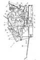
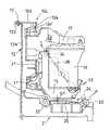
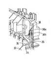
次に、本発明を具体化した実施形態を図面に基づいて説明する。図1は本発明を適用する画像形成装置の一例としてのファクシミリ機能、スキャナ機能、プリンタ機能、複写機能等を備えた多機能装置の概略右側断面図、図2(a)は記録部の正面図、図2(b)は記録部の横断面図、図3はキャリッジ等の正面側斜視図、図4はキャリッジ等の背面側斜視図、図5はフレームと記録ヘッドを搭載したキャリッジの左側側断面図、図6はキャリッジの正面側斜視図、図7はインクカートリッジを除いた記録ヘッドユニットの正面側斜視図、図8は記録ヘッドユニットを搭載したキャリッジの横断面図、図9は傾斜調節機構の部分的分解斜視図、図10は傾斜調節機構を内側から見た斜視図、図11(a)は付勢手段の平面図、図11(b)は付勢手段の斜視図、図11(c)は付勢手段の動作を示す説明図、図12〜図14は線バネの取付けを示す説明図、図15は記録ヘッドユニットの背面の回路基板における板バネの取付け位置を示す斜視図である。
【0016】
多機能装置1の本体ケースは、図1及び図2に示すように、インクジェット式の記録部2を収納し、且つ画像を形成するための被記録媒体としての用紙Pを供給するための給紙トレイ3を後側の上方に傾斜状に備えた合成樹脂製のメイン下ケース1aと、該メイン下ケース1aの上側を覆う合成樹脂製の上ケース1bとからなる。
【0017】
上ケース1bの上面の後寄り部位には原稿載置部4が配置され、その前寄り部位には、原稿読取部としての原稿読取ユニット5が装着され、該原稿読取ユニット5の上側を操作パネル部6にて覆っている。操作パネル部6の表面には、各種ファンクションキーやテンキー等の操作キー部6aと、この操作キー部6aによる入力値や、各種の操作用の文字や数字が表示できる液晶パネル等の表示部6bとを備えている。原稿載置部4には、搬送される原稿の左右両側縁を案内するため、原稿の幅に合わせて左右にスライドする左右一対の原稿ガイド板8が装着されている。
【0018】
なお、メイン下ケース1aの下面は金属板等からなる底カバー板7にて塞がれ、メイン下ケース1aの内部空間には、図示しないが、制御基板、電源基板、電話回線を介して他の電話装置やファクシミリ装置との間で会話やファクシミリデータの送受信を可能にするためのNCU(ネットワークコントロールユニット)基板等の制御部9が配置されている。さらに、図示しないがメイン下ケース1aの側部から外向きに突設した受け台上に、他の電話装置との会話を行うための送受話器(ハンドセット)が載置されている。また、発呼用及びモニタ用のスピーカが、メイン下ケース1a内の右側面の後部側等に固定されている。
【0019】
図1及び図5に示すように、記録部2におけるキャリッジ10はその下部後端が、左右長手の縦長のフレーム12の下部の表面(前面)側に装架された丸軸状のガイド軸11に、摺動可能且つ回動可能に載置されている。
【0020】
また、前記ガイド軸11と平行に延びるタイミングベルト(図示せず)は、フレーム12の一側寄りに配置された従動プーリ(図示せず)と正逆回転可能なステッピングモータ等の駆動モータ(図示せず)の出力軸に固定された駆動プーリ(図示せず)とに巻掛けられ、タイミングベルトの一箇所を前記キャリッジ10に連結することにより、当該キャリッジ10はガイド軸11と平行に往復移動可能となる。なお、前記給紙トレイ3に積層された用紙Pは、図1に示すように、メイン下ケース1aの後部内に配置された従来から周知の構造の給紙機構としての給紙ローラ21と分離パッドあるいは摩擦分離板等からなる分離手段とによって1枚ずつ分離され、分離された用紙Pは、用紙Pの先端タイミング合わせを行うレジストローラ22にて一旦用紙Pの先端の位置を整えて後、記録ヘッドユニット15の下方とプラテン25との間に給送され、搬送下流側の上下対の搬送ローラ23,24にて挟持搬送される途次、印字指令に応じてインク滴を用紙Pの上面に吐出して画像を記録し、その後、排紙トレイ26に排出されるように構成されている。
【0021】
次に図2(a)を参照してキャリッジ10による印字動作について説明する。記録領域から外れてキャリッジ10の移動端近傍、例えばプラテン25の右側には、メンテナンス部27を有する。このメンテナンス部27には、記録ヘッドユニット15のノズル部15aの表面(フェイス面)に付着したインク滴を払拭するためのノズル払拭装置(ワイパ装置)と、該記録ヘッドユニット15のインクの不吐出もしくは吐出不良を回復させたりするためのパージ装置(ノズル吸引装置)28とが配置され、このパージ装置28では、記録ヘッドユニット15のノズル部を吸引キャップ28aにて覆い、図示しないポンプが発生させる負圧により記録ヘッドユニット15内の不良インクを吸引して記録不良から回復させたりするものである。なお、前記メンテナンス部27におけるパージ装置28は、キャリッジ10の移動端部のホームポジション位置(図2の右端位置)にあって、キャリッジ10の記録ヘッドユニット15の全てのノズル部15aを覆ってインクの乾燥を防止するためのキャップ機構(保護装置)を兼ねており、吸引キャップ28aが保護キャップの機能をも果たす。以下、パージ装置を示す28をホームポジションを示す番号としても使用して説明する。また、プラテン25の左端には、記録ヘッドユニット15の各ノズル部15aからインクを試験的に吐出させてインク詰まりを無くするようにするフラッシング部29を備えている。
【0022】
次に、記録部2の構成について説明する。キャリッジ10には、図2〜図5に示すカラーインクジェット式のカートリッジタイプの記録ヘッドユニット15が下向きに着脱可能に装着されている。カラー記録を実行するための記録ヘッドユニット15は、シアン、イエロー、マゼンタ、ブラックの各色のインクを吐出するためのノズル部15aを下面側に有し、この各記録ヘッドユニット15に対して供給するインクが収納された各色毎のインクカートリッジ16は、図2(a)に示すように、記録ヘッドユニット15の上面側に着脱可能に装着できる。そして、キャリッジ10の上端側にて前向きに上下回動可能な押えレバー17(実施形態では4つ)にて、各インクカートリッジ16を下向きに押え固定できる構成である。
【0023】
前記キャリッジ10は、ガラス短繊維を含有させた合成樹脂製の射出成形品であり、図6に示すように、背面板31の左右両側から前向きに左右両側板32が突出され、各側板32の下端部には、記録ヘッドユニット15の底板のうち左右両側を支持する底支持部33、33が内向きに突設されている。キャリッジ10には、前記両底支持部33の間にて記録ヘッドユニット15のノズル部15aを下向きに露出させ、且つ当該記録ヘッドユニット15を回動自在に支持するヘッド収納部70が設けられている。
【0024】
そして、記録ヘッドユニット15の左右両側から外向きに突出させた係合ピン34(図7参照)を、キャリッジ10の左右両側板32に凹み形成した凹所35(図6参照)に配置する(図3及び図4参照)。また、左右両側板32の外側の上端側の取付け孔38に回動可能に取付けられた弾性を有する金属製等の線バネ36の長手方向中途部にて前記各係合ピン34の箇所を斜め下向きに押圧する一方、該各線バネ36の下端側(自由端側)が前記側板32の外側に突出形成された斜め下向きフック状の係止部37にて上向き移動不能に係止され、且つ各線バネ36の自由端側が側板32の外側に不用意に外れないようにして、記録ヘッドユニット15をキャリッジ10に対して強固に且つがたつかないように装着している(図3及び図4参照)。この線バネ36の係止により、記録ヘッドユニット15全体を背面側と底面側とに向かって同時に押圧している。
【0025】
なお、前記取付け孔38は、図12に示すように上下に延びる第1孔部38aと、この第1孔部38aの下端から連続して前方(水平方向)に延びる第2孔部38bとから構成され、図13に示すように、第1孔部38aの内側の前後には第1孔部38aに沿って上下に延びるリブ38cが設けられている。一方、線バネ36の上端側は、取付け穴38の内側に向かってU字型に屈曲され、この屈曲部36aが取付け孔38に係合するようになっている。そのため、線バネ36の屈曲部36aが第1孔部38aに位置する場合には、この屈曲部36aがリブ38cに当接してその動きが規制されるので、線バネ36は上下には動作できるものの回動が不能となる。一方、前記屈曲部36aが第2孔部38bに位置する場合には、第2孔部38bの内側にはリブがないので、図14に示すように、線バネ36は規制を受けずに回動自在となって前記係止部37に自由端側を係止することができ、前記係合ピン34を押圧付勢する。このように、係合ピン34を押圧付勢する際に必ず線バネ36の上端部を第2孔部38bに位置させるようにすることで、線バネ36による付勢において記録ヘッドユニット15に係る押圧方向及び押圧荷重が常に一定になる。
【0026】
また、記録ヘッドユニット15の背面には電気接点(図示せず)が形成されており、この電気接点と接続するように、図15に示される回路基板81が記録ヘッドユニット15の背面側に配置されて、キャリッジ10との間で挟持される。この回路基板81の背面側には、間口方向に長い板バネ82が絶縁体の両面接着フィルムで貼着されている。これにより、記録ヘッドユニット15がヘッド収納部70に収納されたときに、記録ヘッドユニット15の背面にある回路基板81は記録ヘッドユニット15側に対して付勢する付勢力を作用させている。従来、記録ヘッドユニット15の背面とキャリッジ10との間にはスポンジが取り付けられ、スポンジによる付勢力を作用させていたが、スポンジは経時劣化が大きくまた付勢力も不安定であるため、本実施形態のように板バネを用いることで、記録ヘッドユニット15と回路基板81との電気的な接続を安定化させている。
【0027】
次に、キャリッジ10に設けた傾斜調節機構80について詳細に説明する。記録ヘッドユニット10のノズル部15aには、図4に示すように、被記録媒体の搬送方向(矢印C)に沿って延びるノズル列15a′が、上述したシアン、イエロー、マゼンタ、ブラックの4色のインクに対応させて4列形成されている(なお1つのノズル列15a′が千鳥状に配列されている場合もある)。ノズル部15aは製造時に治具などを用いて記録ヘッドユニット15に対して厳密な精度で固着されているが、記録ヘッドユニット15はキャリッジ10に対して着脱自在に設けられているため、着脱に際して、ノズル列15a′がキャリッジ10に対して、正しく位置合わせされない場合が発生する。その場合には、図4に示すように、ノズル列15a′が被記録媒体の搬送方向(矢印C)に対して平行に位置せずに、傾き(角度θ)を有していることになり、印字品質が損なわれる。
【0028】
そのため、傾斜調節機構80では、記録ヘッドユニット15をヘッド収納部70に収納した(この時点で、キャリッジ10に対して記録ヘッドユニット15はある程度の位置決めがなされている)後に、記録ヘッドユニット15のノズル部15aの面が、その平面内で回転するようにキャリッジ10に対して記録ヘッドユニット15を僅かに回動させることで、ノズル列15a′が被記録媒体の搬送方向(図4の矢印C)に対して、厳密に平行となる(角度θ(図4参照)をゼロにする)ように微調節する。
【0029】
記録ヘッドユニット15は、前述したようにキャリッジ10の左右の底支持部33に支持されてヘッド収納部70に収納されているが、具体的には、記録ヘッドユニット15の左右側面15dの下部に、図7に示すように、複数の円柱状の突起部71が外側に向かって突出して設けられ、これら突起部71がキャリッジ10の底支持部33に凹み形成された受部72にそれぞれ落とし込まれるようになっている。図8に示すように、これら突起部71のうちの左側板15dの背面側に設けられた突起部71a(請求項の第1の被保持部に相当する)は、キャリッジ10の左側の底支持部33に設けられた受部72a(請求項の第1の保持部に相当する)に嵌め込まれるが、この突起部71aと受部72aとの当接位置を、前記傾斜調節機構80による記録ヘッドユニット15の回動支点(回転の中心)とするため、これらは、回動に必要な程度の僅かな隙間で嵌合している。その他の突起部71と受部72との嵌合は、記録ヘッドユニット15の回動の妨げとならない程度に、緩やかに嵌め込まれている。
【0030】
一方、傾斜調節機構80は、前記突起部71aと受部72aとによる回動支点と対向する位置、すなわちキャリッジ10の右側板32の背面側の下方に設けられている。これは、前記回動支点とは離間した位置に傾斜調節機構80を設けることで、記録ヘッドユニット15の回動における細かな調節をより容易にできるようにしたためである。
【0031】
傾斜調節機構80としては、キャリッジ10の右側板32の背面寄り下部に、背面側から順に偏心回転体73と付勢手段74とが、内側に突出して各々取り付けられている(図8及び図10参照)。偏心回転体73は、右側板32の内側において外周面を偏心させた回転体であり、付勢手段74は、後に詳述するが、板バネを屈曲して形成したものである。また、傾斜調節機構80としては、記録ヘッドユニット15の左右の側板15dのうち右側板15dの背面寄り下部に、外側に突出する当接部75(請求項の第2の被保持部に相当する)を設けている。そして、この当接部75が偏心回転体73と付勢手段74の間に挟まれて当接するように、記録ヘッドユニット15がヘッド収納部70に収納されている。これにより、常に当接部75が付勢手段74によって偏心回転体73側に付勢されている。この実施形態では、当接部75は略直方体形状を有しており、当接部75の背面側の面が偏心回転体73の外周面に接触し、前面側の面が付勢手段74の板バネの面と接触している。
【0032】
この付勢手段74によって当接部75に作用する背面側への付勢力は、線バネ36から当接部75に伝わる付勢力とは異なり、常に直接当接部75を押圧する付勢力である。そのため、当接部75を偏心回転体73によって前面側に移動させる場合はもとより、背面側に移動させる場合でも、偏心回転体73の外周に当接部75が常に接触する。換言すれば、偏心回転体73の動きに当接部75が常に追従して移動するよう構成している。
【0033】
偏心回転体73は、キャリッジ10の右側板32に円形状に開口して設けられた取付穴32aに、外側から内側に向けて挿入されているが、偏心回転体73の基部73aには、右側板32の外側において、偏心回転体73と連動するレバー部76が取り付けられている。そして、レバー部76の先端部に抜き差し自在の係合ピン77を設ける一方、右側板32の外側にこの係合ピン77と係合する調節用受部78を円弧状に複数配設している。これにより、係合ピン77をどの位置の調節用受部78に係合させるかによって、偏心回転体73の回転角度を変更し、偏心回転体73が当接する当接部75の前後への移動量を変更できるように構成している。このように、偏心回転体73の回動をレバー部76のストロークを利用して大きな円弧で調節することにより、偏心回転体73の回転量、及び当接部75の移動量、ひいてはノズル列15a′の傾き角度θを容易に微調節することができる。なお、具体的な実施形態では、調節用受部78は、角度約90度の円弧部に17個配列されているため、ノズル列15a′の傾きを基準位相に対し±8段階に分けて微調節できるようにしている。
【0034】
前記付勢手段74は、図11(a)に示すように、板バネの先端側をU字型に屈曲させて形成しているが、この屈曲部74bが、キャリッジ10の右側板32に略矩形状に開口して設けられた取付穴32bに、外側から内側に向けて挿入される。そして、図9及び図11(c)に示すように、取付穴32bを形成する内壁面のうちの前面側の内壁面から連続して外側に突出した支持片部32cに、前記板バネの先端部74dが当接しているため、前記屈曲部74bが当接部75に対して弾性力を発揮して押圧付勢することができる。また、屈曲部74bの上部には、ヘッドユニットの当接部75をセット時にガイドするための突出片74cが突設されている。
【0035】
そして、屈曲部74bにおいて当接部75と接触する側の当接面74b′は、対向する当接部75の面と略平行に形成されている。これによれば、図11(c)にて実線で示すように、屈曲部74bの当接面74b′に当接部75が当たる際に面接触となるので、片当たりによって押圧付勢が不安定となることを防止することができる。
【0036】
また、この付勢手段74は、キャリッジ10の側板32の外側に板バネの基端部が取り付けられるが、この基端部に形成された取付穴74aは、図11(b)に示すように、当接部75の移動方向に長い長穴形状に形成され、前記偏心回転体73の軸に遊嵌される。具体的には、図9に示すように、偏心回転体73の取付穴32aの縁に偏心回転体73の軸と同心円状に形成されたリング状縁部32dの外周に、板バネの取付穴74aが装着され、偏心回転体73の基部73aによって脱落しないように押さえられている。このように構成することで、図11(c)にて鎖線で示すように、当接部75が前方に移動するに際して屈曲部74bを前方に押圧すると、これに応じて、付勢手段74が移動方向に僅かに移動する。すなわち、当接部75が移動しても、当接部75と屈曲部74bの当接面74b′との面接触を維持したまま、付勢手段74が当接部75を押圧するので、さらに当接部75の片当たりを防止して押圧付勢の状態を安定化することができる。
【0037】
なお、本発明は、上述のような被記録媒体の搬送方向Cに沿ってノズル列が配置された実施形態だけでなく、被記録媒体の搬送方向Cと交差する方向に沿ってノズル列が延びる形態に傾斜調節機構を適用する形態としてもよい。このような形態は、例えば、被記録媒体の印字可能な幅寸法に必要な長さのノズル列を備えた記録ヘッドユニットを、固定された(移動しない)キャリッジに搭載する場合などである。
【0038】
以上のような多機能装置1は、操作パネル部6における各種キー操作に応じて入力されるオペレータからの各種指令に応じて、各種処理動作の設定、原稿読取ユニット5による原稿画像の読み取り、原稿画像の送信データ化、送信データの符号化、電話回線等の通信回線を介して他のファクシミリ装置に送信するファクシミリデータの送受信、受信データの復号化、復号化したファクシミリデータの記録ユニットでの用紙Pへの記録を実行するという通常のファクシミリ機能の他、原稿読取ユニット5のCIS(密着型イメージセンサ)による原稿読取りと記録部の各ユニットによる用紙Pへカラー画像形成するというコピー(複写)処理機能、図示しないパーソナルコンピュータ(ホストコンピュータ)等の外部装置からプリンタケーブルまたは赤外線等の無線を介して伝送されたプリントデータを受けて、そのデータに応じて用紙Pにカラー画像を形成するプリンタ処理機能、前記原稿読取ユニット5を使って読み取った画像データを前記外部装置へ送信するというスキャナ処理機能をも備えている。
【0039】
なお、本実施形態では、用紙上に画像を形成する装置において、前記した印字品質に影響を及ぼす記録ヘッドユニット15のフェイス面と用紙Pとのギャップの形成及びその大小調整に係る機構を有しているため、この機構を図2〜図5を参照しながら説明する。
【0040】
前記フレーム12には、図5に示すように、前記キャリッジ10の背面板31と略平行に立設する縦板部12aと、該縦板部12aの上端を後向き(前記キャリッジ10の配置部と反対側)に屈曲させて水平支持部12bと、この水平支持部12bの上面に載ってネジ13にて固着されるレール部12cとを備える。レール部12cは、前向きに延びた水平部12dとその前端を下向きに屈曲させた垂直レール部12eとを備えた断面L字状に形成されている。前記レール部12cにおける垂直レール部12eがキャリッジ10の上面後端部に臨んでいる。フレーム12の水平支持部12bに対して水平部12dの取り付け位置を調節することで、縦板部12aと垂直レール部12eとの隙間の間隔を微調節可能に構成されており、これにより、後述する第1当接部50及び第2当接部51が垂直レール部12eの内面である摺接面12e′に当接した状態のままで、記録ヘッドユニット15のノズル面とプラテン25との隙間(ギャップG1,図5参照)の大小を予め調節することができる。
【0041】
そして、前記フレーム12における左側板を前方に屈曲させた左側片12fは第1押動手段として機能し、また、前記フレーム12の水平部12dで、前記メンテナンス部27の上方位置にて下向きに切り起こし形成された舌片12hは第2押動手段として機能する(図2(b)参照)。
【0042】
図3に示すように、キャリッジ10の上面後端部のほぼ中心部にはフレーム12の垂直レール部12eの内面側の摺接面12e′に摺接する合成樹脂製のブロック状の第1当接部50が固着されている。さらに、キャリッジ10の上面後端部には、第1当接部50を挟んで両側に、一対の枢軸54が上向きに立設されている。この各枢軸54に被嵌して回動可能なガイド体41とキャリッジ10の移動方向に長い切替えリンク体40とは、枢支部(図示せず)を介して相対的に水平回動可能に連結されている。すなわち、1つの切替えリンク体40にそれぞれ枢支部(図示せず)の箇所で水平回動可能に連結された一対のガイド体41は、前記一対の枢軸54に対してそれぞれ水平回動可能に支持されることになり、平行リンク機構を構成する。
【0043】
前記左右一対のガイド体41は平面視で同一形状に形成されており、この各ガイド体41には、垂直レール部12eの内面側の摺接面12e′に当接且つ摺接する第2当接部51が設けられている。さらに、切替えリンク体40の上面側に上向きに第2突起部59が形成されている(図3参照)。
【0044】
また、キャリッジ10の上面後端部(背面側)には、平面視L字状のバネ受け60が立設されている。切替えリンク体40の背面の凹み部に挿入されたアーチ状の板バネ61の左右両側の自由端部が前記一対のバネ受け60に支持され、この板バネ61の付勢力にて、切替えリンク体40をキャリッジ10の前方向に押圧する。
【0045】
このように構成されたギャップ調節のための切替え機構30を備えた多機能装置1の、記録ヘッド1とプラテン25の上面(表面であり、被記録媒体としての用紙Pの通過経路)との間隙(ギャップG1)を大小調節する操作及び作用について説明する。例えば前記プリンタ処理機能を実行する場合において、パーソナルコンピュータ等の外部装置内にインストールされたプリンタドライバーソフトを起動させる。そして印刷(記録)する被記録媒体(用紙P)の種別を選択する。このとき、普通紙(例えば、レター用紙やA4用紙等)を選択すると前記ギャップが小さく設定でき、封筒を選択するとギャップが大きく設定できるものとする。
【0046】
まず、普通紙に印刷する場合について説明する。ホームポジション(キャップ位置)28に位置していたキャリッジ10は、印字指令が出ると、矢印A方向に移動し、その移動の略終端部の左側板12fが第1押動手段として、図2(b)左側に示すように、切替えリンク体40の第1突起部42を、図の左から右方向へ押動する。そのため、切替えリンク体40は、右方向(矢印B方向)に移動し、一対のガイド体41が矢印B方向に回転して第2当接部51が収納された状態となり、キャリッジ10の上面に固定されている第1当接部50がフレーム12の摺動面12e′に当接する。キャリッジ10は前記丸軸状のガイド軸11を中心にして自重により下方向に回動し、前記のノズル部15aの下面であるフェイス面がプラテン25の上面に接近してギャップG1が小さい状態に変更され、姿勢保持される。
【0047】
次いで、キャリッジ10を矢印B方向に移動させ、記録(印字)可能範囲内で普通紙に文字など印字することができる。
【0048】
紙厚さの厚い封筒に印字する場合には、ギャップを大きくしないと、用紙搬送経路を移動する封筒がノズル部15aに接触してインクで封筒の表面を汚してしまう。そこで、例えば、前回の印字動作が普通紙への印字であった場合、その印字終了後において、ホームポジション(キャップ位置)28に向かって待避させるべく、前記キャリッジ10を矢印B方向に移動させると、図2(b)の右側に示すように、右側のガイド体41の第2突起部59が、第2押動手段である舌片板12hに当って左方向へ押動される。
【0049】
従って、右側ガイド体41と共に切替えリンク体40及び左側ガイド体41が姿勢変更され、一対のガイド体41における第2当接部51が突出された状態となり、この2つの第2当接部51がフレーム12の摺動面12e′に当接する。そして、記録ヘッド15のノズル部15aの下面であるフェイス面がプラテン25の上面から離れるように、キャリッジ10がガイド軸11の周りに上方向に回動し、ギャップG1が大きい状態(封筒に印刷の状態)に変更され、姿勢保持される。これにより、印刷時に封筒の表面がノズル部15aに擦れず、不必要なインクの付着による汚れを防止することができるのである。
【0050】
なお、本発明は、上述した多機能装置ばかりでなく、プリンタ、複写機、キャリッジ搭載型イメージスキャナについても適用できることは言うまでもない。
【0051】
【発明の作用・効果】
請求項1に記載した発明の画像形成装置は、被記録媒体にインクを吐出する複数のノズルからなる1列または複数列のノズル列をノズル面に持つ記録ヘッドユニットと、前記ノズル列が被記録媒体の搬送方向に沿って延びるように前記記録ヘッドユニットを搭載可能なキャリッジとを備える画像形成装置において、前記キャリッジは、前記ノズル面がその平面内で回転するように前記記録ヘッドユニットの第1の被保持部を前記平面内における回転の中心として保持する第1の保持部を備えており、前記第1の被保持部を回転の中心として前記記録ヘッドユニットを前記キャリッジに対して移動させることにより、被記録媒体の搬送方向に対する前記ノズル列の列方向の傾きを調節する傾斜調節機構と、当該傾斜調節機構と協働することにより前記記録ヘッドユニットの移動に対して押圧付勢する付勢手段とを備えている。
【0052】
これによれば、記録ヘッドユニットのノズル列が被記録媒体の搬送方向と平行となるよう取り付けられていない場合に、傾斜調節機構により記録ヘッドユニットを回動させて前記ノズル列の列方向の傾きを調節するが、当該記録ヘッドユニットが付勢手段で付勢されているため、傾きの調節に際して記録ヘッドユニットが速やかに追従し精度のよい調節が可能となる。
【0053】
また、請求項2に記載した発明の画像形成装置は、被記録媒体にインクを吐出する複数のノズルからなる1列または複数列のノズル列をノズル面に持つ記録ヘッドユニットと、前記ノズル列が被記録媒体の搬送方向と交差する方向に沿って延びるように前記記録ヘッドユニットを搭載可能なキャリッジとを備える画像形成装置において、前記キャリッジは、前記ノズル面がその平面内で回転するように前記記録ヘッドユニットの第1の被保持部を前記平面内における回転の中心として保持する第1の保持部を備えており、前記第1の被保持部を回転の中心として前記記録ヘッドユニットを前記キャリッジに対して移動させることにより、被記録媒体の搬送方向に対する前記ノズル列の列方向の傾きを調節する傾斜調節機構と、当該傾斜調節機構と協働することにより前記記録ヘッドユニットの移動に対して押圧付勢する付勢手段とを備えている。
【0054】
これによれば、記録ヘッドユニットのノズル列が被記録媒体と交差する方向に平行となるよう取り付けられていない場合に、傾斜調節機構により記録ヘッドユニットを回動させて前記ノズル列の列方向の傾きを調節するが、当該記録ヘッドユニットが付勢手段で付勢されているため、傾きの調節に際して記録ヘッドユニットが速やかに追従し精度のよい調節が可能となる。
【0055】
そして、請求項1及び2に記載の発明によれば、前記キャリッジは前記記録ヘッドユニットを前記平面内で回動自在に支持するヘッド収納部を備え、前記傾斜調節機構は、前記ヘッド収納部内における前記第1の保持部と対向する位置に配設されていることを特徴とするものである。これによれば、記録ヘッドユニットを移動させる傾斜調節機構が回転の中心となる第1の保持部と対向した位置に設けられて離間していることにより、回転角度の細かい調節を大きな移動距離で調節することができ、精度のよい調節が可能となる。
【0056】
また、請求項1及び2に記載の発明によれば、前記傾斜調節機構は偏心回転体を備えるとともに、前記記録ヘッドユニットは前記第1の被保持部と対向する位置に第2の被保持部を備えており、前記ヘッド収納部には、その左右側面の何れか一方の内側に突出して前記偏心回転体と前記付勢手段とが設けられており、前記第2の被保持部は前記偏心回転体と前記付勢手段との間に挟持されるように保持されることを特徴とするものである。これによれば、偏心回転体の回転によりこれに当接する第2の被保持部が前後に移動するが、この第2の被保持部は常に付勢手段により偏心回転体側に押圧付勢されているので、前後いずれの方向に移動する場合でも、当接部が偏心回転体に当接して偏心回転体の動きに確実に追従することができる。
【0057】
さらに、請求項1及び2に記載の発明によれば、前記付勢手段を板バネにより構成し、その板バネの基端部に前記第2の被保持部の移動方向に長い長穴形状の取付穴を形成して前記ヘッド収納部の側面外側に取り付けるものであるから、付勢手段である板バネをヘッド収納部の外側から容易に取付けることができる。
そして、請求項3に記載の発明によれば、前記板バネの先端部を屈曲形成して前記第2の被保持部と当接するように前記ヘッド収納部の側面外側から内側に挿入し、前記付勢手段を前記偏心回転体による前記第2の被保持部の移動に応じてこれと同方向に微動可能としたことを特徴とするものである。これによれば、付勢手段が板バネを屈曲させて形成されているため、第2の被保持部が板バネのどの位置にどのような状態で当接するかによって付勢力が変化するが、第2の被保持部が付勢手段の移動に伴って移動することにより、付勢手段は初めに第2の被保持部に当接した姿勢を維持したまま、第2の被保持部に対する押圧付勢力を作用させることができる。
【0058】
また、請求項4に記載の発明は、請求項1乃至3のいずれかに記載の画像形成装置において、前記板バネの基端部に設けられた取付穴は、ヘッド収納部の側面外側において前記偏心回転体の軸に遊嵌されていることを特徴とするものである。これによれば、板バネからなる付勢手段の基端部が、偏心回転体の軸に取り付けられているため、付勢手段は偏心回転体から乖離することはなく、偏心回転体との間で常に力が作用する。
【0059】
また、請求項5に記載の発明は、請求項3または4に記載の画像形成装置において、前記第2の被保持部は略直方体形状に形成され、前記板バネの先端部の屈曲形状のうち前記第2の被保持部と当接する部分は、前記第2の被保持部の端面と略平行に形成されていることを特徴とするものである。これによれば、第2の被保持部の端面は板バネに面接触するため、付勢手段によって第2の被保持部に作用する付勢力が安定化される。
【図面の簡単な説明】
【図1】本発明を適用する画像形成装置の一例としてのファクシミリ機能、スキャナ機能、プリンタ機能、複写機能等を備えた多機能装置の概略右側断面図である。
【図2】(a)は記録部の正面図、(b)は記録部の横断面図である。
【図3】キャリッジ等の正面側斜視図である。
【図4】キャリッジ等の背面側斜視図である。
【図5】フレームと記録ヘッドを搭載したキャリッジの左側側断面図である。
【図6】キャリッジの正面側斜視図である。
【図7】インクカートリッジを除いた記録ヘッドユニットの正面側斜視図である。
【図8】記録ヘッドユニットを搭載したキャリッジの横断面図である。
【図9】傾斜調節機構の部分的分解斜視図である。
【図10】傾斜調節機構を内側から見た斜視図である。
【図11】(a)は付勢手段の平面図、(b)は付勢手段の斜視図、(c)は付勢手段の動作を示す説明図である。
【図12】線バネの取付けを示す説明図である。
【図13】線バネの取付けを示す説明図である。
【図14】線バネの取付けを示す説明図である。
【図15】記録ヘッドユニットの背面の回路基板における板バネの取付け位置を示す斜視図である。
【符号の説明】
1 多機能装置
2 記録部
3 給紙トレイ
4 原稿載置部
5 原稿読取ユニット
6 操作パネル部
7 底カバー板
8 原稿ガイド板
9 制御部
10 キャリッジ
11 ガイド軸
12 フレーム
13 レール部材
15 記録ヘッドユニット
15a ノズル部
15d 側板
16 インクカートリッジ
17 押さえレバー
25 プラテン
26 排紙トレイ
27 メンテナンス部
28 パージ装置
29 フラッシング部
30 ギャップ調節機構
31 背面板
32 側板
32a、32b 取付穴
32c 支持片部
32d リング状縁部
33 底支持部
34 係合ピン
35 凹所
36 線バネ
36a 屈曲部
37 係止部
38 取付け孔
38a 第1孔部
38b 第2孔部
38c リブ
40 リンク体
41 ガイド体
42 第1突起部
43 規制用突起
50 第1当接部
51 第2当接部
54 枢軸
59 第2突起部
60 バネ受け
61 板バネ
70 ヘッド収納部
71、71a 突起部
72、72a 受部
73 偏心回転体
73a 基部
74 付勢手段
75 当接部
76 レバー部
77 係合ピン
78 調節用受部
80 傾斜調節機構
81 回路基板
82 板バネ[0001]
BACKGROUND OF THE INVENTION
The present invention relates to an image forming apparatus such as a printer, a facsimile machine, and a copying machine. More specifically, a recording head unit including a nozzle row including a plurality of nozzles for ejecting ink onto a recording medium is mounted on a carriage. The present invention relates to the structure of an image forming apparatus.
[0002]
[Prior art]
2. Description of the Related Art Conventionally, as an image forming apparatus such as a printer apparatus, a facsimile apparatus, and a copying machine, an ink droplet is ejected from a nozzle of an ink jet head as in an ink jet type image forming apparatus to form an image on a sheet as a recording medium. There is something. In this type of apparatus, for example, one or a plurality of nozzle rows each including a plurality of nozzles are provided on a carriage provided so as to be capable of reciprocating in a direction crossing the conveyance direction of the recording medium so that the nozzle row extends along the conveyance direction. A recording head unit equipped with a recording head unit to be mounted, or a fixed carriage so that a nozzle array consisting of a plurality of nozzles on a recording medium extends long in a direction intersecting the conveyance direction of the recording medium There is a type equipped with. In any type, if the alignment direction of the nozzle row of the recording head unit and the conveyance direction of the recording medium are not correctly aligned, the print quality is greatly affected. Correct alignment with the carriage is extremely important.
[0003]
As a technique for aligning the recording head unit with respect to the carriage, Patent Document 1 describes an inclination adjusting mechanism for adjusting the horizontal inclination of the recording head unit. In this Patent Document 1, an eccentric rotating body (cam) is attached to the lower part of the right side surface of the carriage, and an abutting part (abutting block) protruding outward is provided at the lower part of the right side surface of the recording head unit. The recording head unit is housed in the carriage so that the eccentric rotating body is in contact with the back side of the recording head unit. In this configuration, the abutting portion is moved by the rotation of the eccentric rotator and the recording head unit is rotated with respect to the carriage, so that the row direction of the nozzle rows of the recording head unit is in a correct position with respect to the carriage. Thus, adjustment is made so as to eliminate the inclination with respect to the transport direction of the recording medium (or the direction intersecting the transport direction).
[0004]
On the other hand, in the configuration of Patent Document 1, a non-pressing portion protrudes outward from each upper portion of the left and right side surfaces of the recording head unit, and is engaged with a recess on each of the left and right side surfaces of the carriage. It is pressed diagonally downward by wire springs attached to the side surfaces. As a result, a force that simultaneously presses the recording head unit against the back side and the bottom side of the carriage is generated, thereby preventing backlash and misalignment of the recording head unit that is detachably attached to the carriage.
[0005]
[Patent Document 1]
JP 2003-53947 A (see FIGS. 6 and 10)
[0006]
[Problems to be solved by the invention]
Although the above-described wire spring of Patent Document 1 applies a force that urges the entire recording head unit toward the back side of the carriage, the wire spring is directly pressed on the upper side of the recording head unit. The pressing to the back side did not act directly on the lower contact part which is the pressed part and is separated from the pressed part. Therefore, when the position of the recording head unit with respect to the carriage is adjusted by the tilt adjustment mechanism, the apparatus may be moved when the contact portion is moved too much from the back side to the front side by the eccentric rotating body, or after the adjustment is once completed. If the contact part is displaced from the eccentric rotator to the front side due to an impact or the like, this operation can be performed even if the eccentric rotator is rotated to return the contact part to the back side. There was a case where the contact part did not follow. In such a case, the user has to adjust the recording head unit by hand.
[0007]
The present invention has been made to solve such problems, and includes an inclination adjustment mechanism for correctly aligning the nozzle row of the recording head unit with respect to the conveyance direction of the recording medium. It is an object of the present invention to provide an image forming apparatus capable of performing fine adjustment with high accuracy regardless of the adjustment direction.
[0008]
[Means for Solving the Problems]
In order to solve this problem, an image forming apparatus according to a first aspect of the present invention is a recording head unit having a nozzle surface having one or a plurality of nozzle rows each composed of a plurality of nozzles that eject ink onto a recording medium. And a carriage on which the recording head unit can be mounted so that the nozzle array extends along the conveyance direction of the recording medium, in which the nozzle surface is rotated in the plane. A first holding portion that holds the first held portion of the recording head unit as a center of rotation in the plane, and the recording head unit is arranged with the first held portion as the center of rotation. An inclination adjusting mechanism that adjusts an inclination of the nozzle row in a row direction with respect to a conveyance direction of the recording medium by moving the carriage relative to the carriage; And a biasing means for pressing energizing to the movement of the recording head unit by cooperating with clause mechanism,The carriage includes a head storage portion that rotatably supports the recording head unit in the plane, and the tilt adjustment mechanism is disposed at a position facing the first holding portion in the head storage portion, The tilt adjustment mechanism includes an eccentric rotator, and the first held portion and the second held portion are provided so as to protrude outwardly from the left and right side plates of the recording head unit. The head accommodating portion is provided with the eccentric rotator and the biasing means so as to protrude to the inner side of either one of the left and right side surfaces, and the second held portion is the eccentric rotator and the biasing member. A mounting hole having a long hole shape in the moving direction of the second held portion at the base end of the leaf spring. Forming the head storage part On the side surface outside, the leaf spring is attachedIt is characterized by that.
[0009]
According to a second aspect of the present invention, there is provided an image forming apparatus comprising: a recording head unit having one or a plurality of nozzle rows each having a plurality of nozzles for ejecting ink onto a recording medium; In an image forming apparatus comprising a carriage on which the recording head unit can be mounted so as to extend along a direction intersecting a conveyance direction of a recording medium, the carriage is configured so that the nozzle surface rotates in a plane thereof. A first holding portion that holds the first held portion of the recording head unit as a center of rotation in the plane, and the recording head unit is moved to the carriage with the first held portion as the center of rotation; An inclination adjusting mechanism for adjusting the inclination of the nozzle row in the row direction with respect to the conveyance direction of the recording medium, and the tilt adjuster And a biasing means for pressing energizing to the movement of the recording head unit by preparative cooperating,The carriage includes a head storage portion that rotatably supports the recording head unit in the plane, and the tilt adjustment mechanism is disposed at a position facing the first holding portion in the head storage portion, The tilt adjustment mechanism includes an eccentric rotator, and the first held portion and the second held portion are provided so as to protrude outwardly from the left and right side plates of the recording head unit. The head accommodating portion is provided with the eccentric rotator and the biasing means so as to protrude to the inner side of either one of the left and right side surfaces, and the second held portion is the eccentric rotator and the biasing member. A mounting hole having a long hole shape in the moving direction of the second held portion at the base end of the leaf spring. Forming the head storage part On the side surface outside, the leaf spring is attachedIt is characterized by that.
[0010]
[0011]
[0012]
Also,The invention according to
[0013]
Also,The invention according to
[0014]
Also,The invention according to
[0015]
DETAILED DESCRIPTION OF THE INVENTION
Next, an embodiment of the present invention will be described with reference to the drawings. FIG. 1 is a schematic right sectional view of a multi-function device having a facsimile function, a scanner function, a printer function, a copying function, etc. as an example of an image forming apparatus to which the present invention is applied, and FIG. 2A is a front view of a recording unit. 2B is a cross-sectional view of the recording unit, FIG. 3 is a front perspective view of the carriage, etc. FIG. 4 is a rear perspective view of the carriage, etc. FIG. 5 is a left side of the carriage on which the frame and the recording head are mounted. FIG. 6 is a front perspective view of the carriage, FIG. 7 is a front perspective view of the recording head unit excluding the ink cartridge, FIG. 8 is a transverse sectional view of the carriage on which the recording head unit is mounted, and FIG. FIG. 10 is a perspective view of the tilt adjusting mechanism viewed from the inside, FIG. 11A is a plan view of the urging means, FIG. 11B is a perspective view of the urging means, and FIG. (C) is explanatory drawing which shows operation | movement of a biasing means. 12 to 14 is an explanatory view showing the attachment of the wire spring, Figure 15 is a perspective view showing the mounting position of the leaf spring in the circuit board on the back of the recording head unit.
[0016]
As shown in FIGS. 1 and 2, the main body case of the multi-function device 1 houses the ink
[0017]
A
[0018]
The lower surface of the main
[0019]
As shown in FIGS. 1 and 5, the
[0020]
A timing belt (not shown) extending in parallel with the
[0021]
Next, the printing operation by the
[0022]
Next, the configuration of the
[0023]
The
[0024]
Then, the engagement pins 34 (see FIG. 7) protruding outward from the left and right sides of the
[0025]
As shown in FIG. 12, the mounting
[0026]
Further, an electrical contact (not shown) is formed on the back surface of the
[0027]
Next, the
[0028]
Therefore, in the
[0029]
As described above, the
[0030]
On the other hand, the
[0031]
As the
[0032]
Unlike the urging force transmitted from the
[0033]
The
[0034]
As shown in FIG. 11A, the urging means 74 is formed by bending the distal end side of the leaf spring into a U-shape, and this
[0035]
The
[0036]
Further, the biasing means 74 has a base end portion of a leaf spring attached to the outside of the
[0037]
In the present invention, the nozzle row extends not only in the embodiment in which the nozzle row is arranged along the conveyance direction C of the recording medium as described above but also in a direction intersecting the conveyance direction C of the recording medium. It is good also as a form which applies a tilt adjustment mechanism to a form. Such a form is, for example, a case where a recording head unit including a nozzle row having a length necessary for the printable width dimension of a recording medium is mounted on a fixed (non-moving) carriage.
[0038]
The multi-function device 1 as described above is configured to set various processing operations, read a document image by the
[0039]
In the present embodiment, the apparatus for forming an image on a sheet has a mechanism for forming a gap between the face surface of the
[0040]
As shown in FIG. 5, the
[0041]
The left-
[0042]
As shown in FIG. 3, a block-shaped first abutment made of synthetic resin that is slidably in contact with the
[0043]
The pair of left and
[0044]
In addition, an L-shaped
[0045]
The gap between the recording head 1 and the upper surface of the platen 25 (the surface, the passage path of the paper P as a recording medium) of the multi-function device 1 including the
[0046]
First, the case of printing on plain paper will be described. When a print command is issued, the
[0047]
Next, the
[0048]
When printing on a thick paper envelope, unless the gap is increased, the envelope moving in the paper conveyance path contacts the
[0049]
Accordingly, the posture of the
[0050]
Needless to say, the present invention can be applied not only to the above-described multifunction apparatus but also to a printer, a copying machine, and a carriage-mounted image scanner.
[0051]
[Operation and effect of the invention]
An image forming apparatus according to a first aspect of the present invention is a recording head unit having a nozzle surface having one or a plurality of nozzle rows each having a plurality of nozzles for ejecting ink onto a recording medium; An image forming apparatus including a carriage on which the recording head unit can be mounted so as to extend along a medium conveyance direction. The carriage has a first surface of the recording head unit such that the nozzle surface rotates in a plane thereof. A first holding portion that holds the held portion as a center of rotation in the plane, and the recording head unit is moved relative to the carriage with the first held portion as the center of rotation. By adjusting the tilt adjustment mechanism for adjusting the tilt in the row direction of the nozzle row with respect to the conveyance direction of the recording medium, and by cooperating with the tilt adjustment mechanism. And a biasing means for pressing energizing to the movement of the recording head unitI have.
[0052]
According to this, when the nozzle array of the recording head unit is not attached so as to be parallel to the conveyance direction of the recording medium, the inclination of the recording head unit is rotated by the inclination adjusting mechanism to tilt the nozzle array in the column direction. However, since the recording head unit is urged by the urging means, the recording head unit can quickly follow when adjusting the tilt, and can be adjusted with high accuracy.
[0053]
According to a second aspect of the present invention, there is provided an image forming apparatus comprising: a recording head unit having one or a plurality of nozzle rows each having a plurality of nozzles for ejecting ink onto a recording medium; In an image forming apparatus comprising a carriage on which the recording head unit can be mounted so as to extend along a direction intersecting a conveyance direction of a recording medium, the carriage is configured so that the nozzle surface rotates in a plane thereof. A first holding portion that holds the first held portion of the recording head unit as a center of rotation in the plane, and the recording head unit is moved to the carriage with the first held portion as the center of rotation; An inclination adjusting mechanism for adjusting the inclination of the nozzle row in the row direction with respect to the conveyance direction of the recording medium, and the tilt adjuster And a biasing means for pressing energizing to the movement of the recording head unit by preparative cooperatingI have.
[0054]
According to this, when the nozzle row of the recording head unit is not attached so as to be parallel to the direction intersecting the recording medium, the recording head unit is rotated by the tilt adjustment mechanism to move in the row direction of the nozzle row. Although the inclination is adjusted, since the recording head unit is urged by the urging means, the recording head unit can quickly follow the adjustment of the inclination and can be adjusted with high accuracy.
[0055]
And according to invention of
[0056]
Also,According to invention of
[0057]
Furthermore, according to invention of
And according to invention of
[0058]
Also,Claim 4The invention described inAny one of claims 1 to 3The mounting hole provided in the base end portion of the leaf spring is loosely fitted to the shaft of the eccentric rotating body outside the side surface of the head storage portion. . According to this, since the base end portion of the urging means composed of the leaf spring is attached to the shaft of the eccentric rotator, the urging means does not deviate from the eccentric rotator. The force always works.
[0059]
Also,Claim 5The invention described
[Brief description of the drawings]
FIG. 1 is a schematic right sectional view of a multi-function device having a facsimile function, a scanner function, a printer function, a copying function, and the like as an example of an image forming apparatus to which the present invention is applied.
2A is a front view of a recording unit, and FIG. 2B is a cross-sectional view of the recording unit.
FIG. 3 is a front perspective view of a carriage and the like.
FIG. 4 is a rear perspective view of a carriage or the like.
FIG. 5 is a left side sectional view of a carriage on which a frame and a recording head are mounted.
FIG. 6 is a front perspective view of a carriage.
FIG. 7 is a front perspective view of the recording head unit excluding the ink cartridge.
FIG. 8 is a cross-sectional view of a carriage on which a recording head unit is mounted.
FIG. 9 is a partially exploded perspective view of the tilt adjustment mechanism.
FIG. 10 is a perspective view of the tilt adjustment mechanism as viewed from the inside.
11A is a plan view of the urging means, FIG. 11B is a perspective view of the urging means, and FIG. 11C is an explanatory view showing the operation of the urging means.
FIG. 12 is an explanatory view showing attachment of a wire spring.
FIG. 13 is an explanatory view showing attachment of a wire spring.
FIG. 14 is an explanatory view showing attachment of a wire spring.
FIG. 15 is a perspective view showing a mounting position of a leaf spring on a circuit board on the back surface of the recording head unit.
[Explanation of symbols]
1 Multifunctional device
2 Recording section
3 Paper tray
4 Document placement section
5 Document reading unit
6 Operation panel
7 Bottom cover plate
8 Document guide plate
9 Control unit
10 Carriage
11 Guide shaft
12 frames
13 Rail member
15 Recording head unit
15a Nozzle part
15d side plate
16 Ink cartridge
17 Holding lever
25 platen
26 Output tray
27 Maintenance Department
28 Purge device
29 Flushing section
30 Gap adjustment mechanism
31 Back plate
32 side plate
32a, 32b Mounting hole
32c support piece
32d ring edge
33 Bottom support
34 Engagement pin
35 recess
36 wire spring
36a bent part
37 Locking part
38 Mounting hole
38a 1st hole
38b Second hole
38c rib
40 links
41 Guide body
42 First protrusion
43 Control projection
50 1st contact part
51 2nd contact part
54 Axis
59 Second protrusion
60 Spring support
61 leaf spring
70 Head compartment
71, 71a Projection
72, 72a receiving part
73 Eccentric rotating body
73a base
74 Energizing means
75 Contact part
76 Lever part
77 engaging pin
78 Receiving part for adjustment
80 Tilt adjustment mechanism
81 Circuit board
82 leaf spring
Claims (5)
Translated fromJapanese前記キャリッジは、前記ノズル面がその平面内で回転するように前記記録ヘッドユニットの第1の被保持部を前記平面内における回転の中心として保持する第1の保持部を備えており、
前記第1の被保持部を回転の中心として前記記録ヘッドユニットを前記キャリッジに対して移動させることにより、被記録媒体の搬送方向に対する前記ノズル列の列方向の傾きを調節する傾斜調節機構と、
当該傾斜調節機構と協働することにより前記記録ヘッドユニットの移動に対して押圧付勢する付勢手段とを備え、
前記キャリッジは前記記録ヘッドユニットを前記平面内で回動自在に支持するヘッド収納部を備え、前記傾斜調節機構は、前記ヘッド収納部内における前記第1の保持部と対向する位置に配設され、
前記傾斜調節機構は偏心回転体を備えるとともに、前記第1の被保持部と第2の被保持部とが前記記録ヘッドユニットにおける左右両側板に外向きに突出するように設けられており、
前記ヘッド収納部には、その左右側面の何れか一方の内側に突出して前記偏心回転体と前記付勢手段とが設けられており、
前記第2の被保持部は前記偏心回転体と前記付勢手段との間に挟持されるように保持され、
前記付勢手段を板バネにより構成し、その板バネの基端部に前記第2の被保持部の移動方向に長い長穴形状の取付穴を形成して、前記ヘッド収納部の側面外側に、前記板バネが取り付けられていることを特徴とする画像形成装置。A recording head unit having one or more nozzle rows each having a plurality of nozzles for ejecting ink on the recording medium on a nozzle surface; and the recording head such that the nozzle rows extend along a conveyance direction of the recording medium. In an image forming apparatus including a carriage on which a unit can be mounted,
The carriage includes a first holding portion that holds the first held portion of the recording head unit as a center of rotation in the plane so that the nozzle surface rotates in the plane.
An inclination adjusting mechanism that adjusts the inclination of the nozzle row in the row direction with respect to the recording medium conveyance direction by moving the recording head unit with respect to the carriage with the first held portion as the center of rotation;
Urging means for pressing and urging the movement of the recording head unit by cooperating with the tilt adjustment mechanism;
The carriage includes a head storage portion that rotatably supports the recording head unit in the plane, and the tilt adjustment mechanism is disposed at a position facing the first holding portion in the head storage portion,
The tilt adjusting mechanism includes an eccentric rotating body, and the first held portion and the second held portion are provided so as to protrude outwardly from the left and right side plates of the recording head unit,
The head housing portion is provided with the eccentric rotator and the biasing means so as to protrude inside one of the left and right side surfaces thereof,
The second held portion is held so as to be sandwiched between the eccentric rotating body and the urging means,
The biasing means is constituted by a leaf spring, and a long hole-shaped attachment hole is formed at the base end portion of the leaf spring in the moving direction of the second held portion, and is formed outside the side surface of the head housing portion. An image forming apparatus having theleaf spring attached thereto.
前記キャリッジは、前記ノズル面がその平面内で回転するように前記記録ヘッドユニットの第1の被保持部を前記平面内における回転の中心として保持する第1の保持部を備えており、
前記第1の被保持部を回転の中心として前記記録ヘッドユニットを前記キャリッジに対して移動させることにより、被記録媒体の搬送方向に対する前記ノズル列の列方向の傾きを調節する傾斜調節機構と、
当該傾斜調節機構と協働することにより前記記録ヘッドユニットの移動に対して押圧付勢する付勢手段とを備え、
前記キャリッジは前記記録ヘッドユニットを前記平面内で回動自在に支持するヘッド収納部を備え、前記傾斜調節機構は、前記ヘッド収納部内における前記第1の保持部と対向する位置に配設され、
前記傾斜調節機構は偏心回転体を備えるとともに、前記第1の被保持部と第2の被保持部とが前記記録ヘッドユニットにおける左右両側板に外向きに突出するように設けられており、
前記ヘッド収納部には、その左右側面の何れか一方の内側に突出して前記偏心回転体と前記付勢手段とが設けられており、
前記第2の被保持部は前記偏心回転体と前記付勢手段との間に挟持されるように保持され、
前記付勢手段を板バネにより構成し、その板バネの基端部に前記第2の被保持部の移動方向に長い長穴形状の取付穴を形成して、前記ヘッド収納部の側面外側に、前記板バネが取り付けられていることを特徴とする画像形成装置。A recording head unit having one or a plurality of nozzle rows each having a plurality of nozzles for ejecting ink on a recording medium on a nozzle surface, and the nozzle rows extending along a direction intersecting the conveyance direction of the recording medium An image forming apparatus comprising a carriage on which the recording head unit can be mounted,
The carriage includes a first holding portion that holds the first held portion of the recording head unit as a center of rotation in the plane so that the nozzle surface rotates in the plane.
An inclination adjusting mechanism that adjusts the inclination of the nozzle row in the row direction with respect to the recording medium conveyance direction by moving the recording head unit with respect to the carriage with the first held portion as the center of rotation;
Urging means for pressing and urging the movement of the recording head unit by cooperating with the tilt adjustment mechanism;
The carriage includes a head storage portion that rotatably supports the recording head unit in the plane, and the tilt adjustment mechanism is disposed at a position facing the first holding portion in the head storage portion,
The tilt adjusting mechanism includes an eccentric rotating body, and the first held portion and the second held portion are provided so as to protrude outwardly from the left and right side plates of the recording head unit,
The head housing portion is provided with the eccentric rotator and the biasing means so as to protrude inside one of the left and right side surfaces thereof,
The second held portion is held so as to be sandwiched between the eccentric rotating body and the urging means,
The biasing means is constituted by a leaf spring, and a long hole-shaped attachment hole is formed at the base end portion of the leaf spring in the moving direction of the second held portion, and is formed outside the side surface of the head housing portion. An image forming apparatus having theleaf spring attached thereto.
Priority Applications (2)
| Application Number | Priority Date | Filing Date | Title |
|---|---|---|---|
| JP2003121584AJP3931981B2 (en) | 2003-04-25 | 2003-04-25 | Image forming apparatus |
| US10/831,287US7163277B2 (en) | 2003-04-25 | 2004-04-26 | Image forming apparatus and image scanner |
Applications Claiming Priority (1)
| Application Number | Priority Date | Filing Date | Title |
|---|---|---|---|
| JP2003121584AJP3931981B2 (en) | 2003-04-25 | 2003-04-25 | Image forming apparatus |
Publications (2)
| Publication Number | Publication Date |
|---|---|
| JP2004322514A JP2004322514A (en) | 2004-11-18 |
| JP3931981B2true JP3931981B2 (en) | 2007-06-20 |
Family
ID=33500104
Family Applications (1)
| Application Number | Title | Priority Date | Filing Date |
|---|---|---|---|
| JP2003121584AExpired - Fee RelatedJP3931981B2 (en) | 2003-04-25 | 2003-04-25 | Image forming apparatus |
Country Status (2)
| Country | Link |
|---|---|
| US (1) | US7163277B2 (en) |
| JP (1) | JP3931981B2 (en) |
Families Citing this family (7)
| Publication number | Priority date | Publication date | Assignee | Title |
|---|---|---|---|---|
| US7517046B2 (en)* | 2005-05-09 | 2009-04-14 | Silverbrook Research Pty Ltd | Mobile telecommunications device with printhead capper that is held in uncapped position by media |
| ATE532639T1 (en)* | 2005-09-07 | 2011-11-15 | Retail Inkjet Solutions | SYSTEM AND METHOD FOR REFILLING INK JET CARTRIDGES |
| US8220903B2 (en)* | 2009-11-18 | 2012-07-17 | Eastman Kodak Company | Ink tank feature for improved mounting reliability |
| JP5446956B2 (en)* | 2010-02-12 | 2014-03-19 | セイコーエプソン株式会社 | Liquid ejector |
| JP2011240584A (en)* | 2010-05-18 | 2011-12-01 | Seiko Epson Corp | Fluid jet apparatus |
| JP5804921B2 (en)* | 2011-12-07 | 2015-11-04 | 株式会社ミマキエンジニアリング | Carriage and inkjet device |
| JP7082086B2 (en)* | 2019-04-25 | 2022-06-07 | コニカミノルタ株式会社 | Ink supply device and image forming device |
Family Cites Families (10)
| Publication number | Priority date | Publication date | Assignee | Title |
|---|---|---|---|---|
| JP2718805B2 (en)* | 1990-04-06 | 1998-02-25 | キヤノン株式会社 | Ink jet recording head unit and ink jet recording apparatus equipped with the unit |
| ES2105788T3 (en) | 1990-04-06 | 1997-10-16 | Canon Kk | HEAD UNIT FOR INK JET PRINTING AND APPARATUS FOR INK JET PRINTING. |
| JPH08258369A (en)* | 1995-03-22 | 1996-10-08 | Seiko Epson Corp | Inkjet printer |
| JPH10109458A (en)* | 1996-08-14 | 1998-04-28 | Seiko Epson Corp | Printhead position adjustment mechanism in ink jet printing apparatus |
| EP1080915B1 (en)* | 1999-09-03 | 2011-07-20 | Canon Kabushiki Kaisha | Liquid ejecting head unit |
| JP2002067279A (en) | 2000-08-30 | 2002-03-05 | Seiko Epson Corp | Recording head position adjustment mechanism for inkjet recording device |
| US6883898B2 (en)* | 2000-12-27 | 2005-04-26 | Seiko Epson Corporation | Printing using a print head with staggered nozzle arrangements |
| JP2002205439A (en) | 2001-01-10 | 2002-07-23 | Seiko Epson Corp | Carriage and recording apparatus having the same |
| JP2003053947A (en) | 2001-08-22 | 2003-02-26 | Brother Ind Ltd | Image forming device |
| US6705702B2 (en)* | 2001-10-30 | 2004-03-16 | Hewlett-Packard Development Company, L.P. | Inkjet printing using pigmented and dye-based inks |
- 2003
- 2003-04-25JPJP2003121584Apatent/JP3931981B2/ennot_activeExpired - Fee Related
- 2004
- 2004-04-26USUS10/831,287patent/US7163277B2/ennot_activeExpired - Lifetime
Also Published As
| Publication number | Publication date |
|---|---|
| US20040263568A1 (en) | 2004-12-30 |
| JP2004322514A (en) | 2004-11-18 |
| US7163277B2 (en) | 2007-01-16 |
Similar Documents
| Publication | Publication Date | Title |
|---|---|---|
| US6666542B2 (en) | Ink cartridge for printer or the like and ink cartridge positioning and locking mechanism | |
| JP3858998B2 (en) | Image forming apparatus | |
| CN102085763B (en) | Image forming apparatus and control method | |
| US6690494B1 (en) | Tension adjustable mechanism for reciprocatingly moving print/read head device | |
| JP2004122439A (en) | Carriage and image forming apparatus | |
| JP3767568B2 (en) | Image forming apparatus | |
| JP3970097B2 (en) | Recording device | |
| JP3931981B2 (en) | Image forming apparatus | |
| US7607663B2 (en) | Recording medium transport device and image forming apparatus | |
| JP3874109B2 (en) | Image forming apparatus | |
| JP4560336B2 (en) | Recording device | |
| JP4174635B2 (en) | Inkjet recording device | |
| JP3901478B2 (en) | Unit connecting device, recording device | |
| JP2003053999A (en) | Image forming device | |
| JP3901479B2 (en) | Recording device | |
| JP4600465B2 (en) | Carriage and image forming apparatus | |
| US7461915B2 (en) | Inkjet recording apparatus | |
| JP2000062199A (en) | Ink jet recording device | |
| JP2007119233A (en) | Image recording device | |
| JP2003053947A (en) | Image forming device | |
| JP2004050462A (en) | Recording device | |
| US7899385B2 (en) | Image forming apparatus | |
| JP2007030195A (en) | Inkjet recording device | |
| JP3918910B2 (en) | Recording device | |
| JP3514126B2 (en) | Image forming device |
Legal Events
| Date | Code | Title | Description |
|---|---|---|---|
| A621 | Written request for application examination | Free format text:JAPANESE INTERMEDIATE CODE: A621 Effective date:20040928 | |
| A977 | Report on retrieval | Free format text:JAPANESE INTERMEDIATE CODE: A971007 Effective date:20061004 | |
| A131 | Notification of reasons for refusal | Free format text:JAPANESE INTERMEDIATE CODE: A131 Effective date:20061011 | |
| A521 | Written amendment | Free format text:JAPANESE INTERMEDIATE CODE: A523 Effective date:20061206 | |
| TRDD | Decision of grant or rejection written | ||
| A01 | Written decision to grant a patent or to grant a registration (utility model) | Free format text:JAPANESE INTERMEDIATE CODE: A01 Effective date:20070221 | |
| A61 | First payment of annual fees (during grant procedure) | Free format text:JAPANESE INTERMEDIATE CODE: A61 Effective date:20070306 | |
| R150 | Certificate of patent or registration of utility model | Ref document number:3931981 Country of ref document:JP Free format text:JAPANESE INTERMEDIATE CODE: R150 Free format text:JAPANESE INTERMEDIATE CODE: R150 | |
| FPAY | Renewal fee payment (event date is renewal date of database) | Free format text:PAYMENT UNTIL: 20100323 Year of fee payment:3 | |
| FPAY | Renewal fee payment (event date is renewal date of database) | Free format text:PAYMENT UNTIL: 20110323 Year of fee payment:4 | |
| FPAY | Renewal fee payment (event date is renewal date of database) | Free format text:PAYMENT UNTIL: 20120323 Year of fee payment:5 | |
| FPAY | Renewal fee payment (event date is renewal date of database) | Free format text:PAYMENT UNTIL: 20120323 Year of fee payment:5 | |
| FPAY | Renewal fee payment (event date is renewal date of database) | Free format text:PAYMENT UNTIL: 20130323 Year of fee payment:6 | |
| FPAY | Renewal fee payment (event date is renewal date of database) | Free format text:PAYMENT UNTIL: 20130323 Year of fee payment:6 | |
| FPAY | Renewal fee payment (event date is renewal date of database) | Free format text:PAYMENT UNTIL: 20140323 Year of fee payment:7 | |
| LAPS | Cancellation because of no payment of annual fees |