JP3930977B2 - Sample processing system - Google Patents
Sample processing systemDownload PDFInfo
- Publication number
- JP3930977B2 JP3930977B2JP21770498AJP21770498AJP3930977B2JP 3930977 B2JP3930977 B2JP 3930977B2JP 21770498 AJP21770498 AJP 21770498AJP 21770498 AJP21770498 AJP 21770498AJP 3930977 B2JP3930977 B2JP 3930977B2
- Authority
- JP
- Japan
- Prior art keywords
- sample
- rack
- emergency
- processing
- unit
- Prior art date
- Legal status (The legal status is an assumption and is not a legal conclusion. Google has not performed a legal analysis and makes no representation as to the accuracy of the status listed.)
- Expired - Lifetime
Links
Images


Classifications
- G—PHYSICS
- G01—MEASURING; TESTING
- G01N—INVESTIGATING OR ANALYSING MATERIALS BY DETERMINING THEIR CHEMICAL OR PHYSICAL PROPERTIES
- G01N35/00—Automatic analysis not limited to methods or materials provided for in any single one of groups G01N1/00 - G01N33/00; Handling materials therefor
- G01N35/02—Automatic analysis not limited to methods or materials provided for in any single one of groups G01N1/00 - G01N33/00; Handling materials therefor using a plurality of sample containers moved by a conveyor system past one or more treatment or analysis stations
- G01N35/026—Automatic analysis not limited to methods or materials provided for in any single one of groups G01N1/00 - G01N33/00; Handling materials therefor using a plurality of sample containers moved by a conveyor system past one or more treatment or analysis stations having blocks or racks of reaction cells or cuvettes
- G—PHYSICS
- G01—MEASURING; TESTING
- G01N—INVESTIGATING OR ANALYSING MATERIALS BY DETERMINING THEIR CHEMICAL OR PHYSICAL PROPERTIES
- G01N35/00—Automatic analysis not limited to methods or materials provided for in any single one of groups G01N1/00 - G01N33/00; Handling materials therefor
- G01N35/00584—Control arrangements for automatic analysers
- G01N35/0092—Scheduling
- G01N35/0095—Scheduling introducing urgent samples with priority, e.g. Short Turn Around Time Samples [STATS]
- Y—GENERAL TAGGING OF NEW TECHNOLOGICAL DEVELOPMENTS; GENERAL TAGGING OF CROSS-SECTIONAL TECHNOLOGIES SPANNING OVER SEVERAL SECTIONS OF THE IPC; TECHNICAL SUBJECTS COVERED BY FORMER USPC CROSS-REFERENCE ART COLLECTIONS [XRACs] AND DIGESTS
- Y10—TECHNICAL SUBJECTS COVERED BY FORMER USPC
- Y10T—TECHNICAL SUBJECTS COVERED BY FORMER US CLASSIFICATION
- Y10T436/00—Chemistry: analytical and immunological testing
- Y10T436/11—Automated chemical analysis
- Y10T436/113332—Automated chemical analysis with conveyance of sample along a test line in a container or rack
- Y10T436/114165—Automated chemical analysis with conveyance of sample along a test line in a container or rack with step of insertion or removal from test line
Landscapes
- Chemical & Material Sciences (AREA)
- Physics & Mathematics (AREA)
- Health & Medical Sciences (AREA)
- Life Sciences & Earth Sciences (AREA)
- Analytical Chemistry (AREA)
- Biochemistry (AREA)
- General Health & Medical Sciences (AREA)
- General Physics & Mathematics (AREA)
- Immunology (AREA)
- Pathology (AREA)
- Chemical Kinetics & Catalysis (AREA)
- Automatic Analysis And Handling Materials Therefor (AREA)
Description
Translated fromJapanese【0001】
【発明の属する技術的分野】
本発明は、検体処理システムに係り、特に血液や尿の如き生体試料を検体として物理的処理又は化学的処理を行う検体処理システムに関する。
【0002】
【従来の技術】
血液や尿の如き生体試料からなる検体の多数に対して分析処理する場合には、検体の入った検体容器が検体ラックと呼称されるホルダーにより保持された状態でしばしば取り扱われる。このような検体ラックに保持された検体を分析測定機能を備えた分析ユニットへ分取する方法には、大別して2つのタイプが知られている。
【0003】
その1つは、例えば、特開平3−285175号公報に示されているように、ラック供給部からラック収納部へ向けて検体ラックを搬送する途中において検体ラックを停止させ、搬送ライン上の検体ラックから分析ユニット内の反応容器へ、ピペッタを用いて検体を分注する方法である。
【0004】
他の1つは、例えば、特開平9−281113号公報に示されているように、主搬送ラインに沿って配置した分析ユニット内に主搬送ラインに対するバイパスラインを形成し、主搬送ラインにより搬送された検体ラックをバイパスラインに移載したあと、バイパスライン上の検体ラックから分析ユニットの反応容器へ分注器を用いて検体を分注する方法である。
【0005】
【発明が解決しようとする課題】
遠心分離ユニット、親検体から子検体への分注ユニット、分析ユニットなどの検体処理ユニットにより多数の検体を効率的に処理するには、検体を有する検体ラックを処理位置へ間断なく供給することにより検体処理ユニットに検体待ち状態を生じさせないように構成することが望ましい。そのためには、分析ユニットへの分注位置に近接して複数の検体ラックを待機させるための待機エリアを設けておき、分注位置にて先行の検体ラック上の検体の分注が終了すれば直ちに待機エリアから次の検体ラックを分注位置に位置づける方法が有効である。
【0006】
しかしながら、このような待機エリアを設ける構成にすると、緊急に分析処理をしなければならない検体が依頼された場合であっても待機エリア上における分注処理待ちの多数の一般検体が処理された後でなければ緊急検体を処理できないという問題が生ずる。すなわち、特開平3−285175号公報のようなタイプの場合には、緊急検体の搬送開始前に搬送ライン上にて既に多数の検体ラックが処理待ちをしており、特開平9−281113号公報のようなタイプの場合には、緊急検体の搬送開始前にバイパスライン上にて既に多数の検体ラックが処理待ちをしていることになるので、緊急検体の処理結果を短時間内に得ることができない。
【0007】
本発明の目的は、多数の検体に対しては効率的な連続処理が可能であって、特に緊急を要する検体の処理の際は処理待ち時間を少なくできる検体処理システムを提供することにある。
【0008】
【課題を解決するための手段】
本発明が適用される検体処理システムにおける検体処理ユニットは、検体ラックから検体を分注するための検体分注装置を具備する。一般検体を有する検体ラックが投入される一般検体投入部又は緊急検体を有する検体ラックが投入される緊急検体投入部からの検体ラックは、ラック搬送手段により検体処理ユニットへ搬送される。分注前の検体ラックを待機させる待機エリアは、一般検体投入部と検体処理ユニットの間に形成するか、又は検体処理ユニット内のバイパスラインに形成する。
【0009】
一般処理対応モードのときは、待機エリアにおいて、待機可能な検体ラック数又は分析項目が所定数であるように検体処理ユニット又はラック搬送手段を制御し、緊急処理対応モードのときは、待機エリアの待機可能な検体ラック数又は分析項目数が上記所定数より少ない数であるように検体処理ユニット又はラック搬送手段を制御する。
【0010】
待機エリアにおける監視対象は、検体ラック数や分析項目数の他に、最大の分注予定回数又は最長の分注待ち時間であってもよい。緊急検体の処理予定があるときは、一般処理対応モードから緊急処理対応モードに変更され、緊急処理対応モードの方が待機数又は待機時間が小さくなるように制限される。
【0011】
本発明に基づく望ましい実施例では、検体処理ユニットが複数配置され、各検体処理ユニット毎に緊急処理対応モードを適用できるように指示するための指示装置を有する。緊急処理対応モードは、待機数(検体ラック数、分析項目数、最大分注予定回数など)や待機時間を複数段階のレベルに変化させることができ、指示装置により所望のレベルを選択する又は調整することができる。また、1日又は稼動時間を複数の時間帯に分けて、各時間帯毎に緊急処理対応モードのレベルを選択又は調整することができる。このようなレベルの選択又は調整は、指示装置に含まれる画面表示装置を通して行うことが望ましい。
【0012】
【発明の実施の形態】
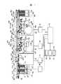
図1〜図4を参照して、本発明の一実施例である検体処理システムの構成を説明する。
【0013】
図1の一般検体投入部40には、2個のラックトレイ151、152が着脱可能に架設される。各ラックトレイには多数の検体ラック2を並べて収容できる。各ラックトレイ上の検体ラック2は、レバー駆動部41又は42により水平方向に運動する可動レバー351又は352によって、1個ずつ供給ライン47に押し出される。図1の例における検体ラック2は、箱型の容器ホルダーであって、5本の検体容器を保持しているが、検体ラック2の形態及び保持し得る検体容器数は本例のものに限られるものではなく、1個以上の検体容器を保持でき搬送ライン上を移動できるものであればよく、種々の変形例を採用できる。
【0014】
一般検体投入部40に投入される検体ラックは、特に緊急性を要しない通常の一般検体が入った検体容器を保持している。検体ラックが移動し得る供給ライン47の上流側には、緊急検体投入部45が配設される。この緊急検体投入部45には、緊急に処理結果(例えば分析結果)が必要な緊急検体が入った検体容器を保持した検体ラックが投入される。緊急検体投入部45の緊急検体受取り位置211にセットされた検体ラックは、一般検体投入部40からの検体ラックよりも優先して搬送ラインへの引渡し位置217へ移される。
【0015】
図1のシステムでは、一般検体投入部40とラック収納部60の間に、検体処理ユニットとして3種の分析ユニットが配置されている。分析ユニット10は、電解質成分をイオン選択電極を配置した測定部により分析測定する検体処理ユニットである。搬送ライン上の検体ラックから分析ユニット10内の検体希釈容器13へ検体分注装置181のピペットノズルにより検体が分取され、その検体が希釈液で希釈された後、測定部へ導入され、ナトリウム、カリウム、塩素などの各イオンが測定される。
【0016】
分析ユニット20及び分析ユニット30は、検体と試薬を混合して反応させ、反応によって生じた呈色液を吸光光度計のような光学測定装置により測定する検体処理ユニットである。
【0017】
ラック収納部60は、検体処理された搬送済みの検体ラック2をラックトレイ161又は162に収納する。ラック収納部60の収納ライン61に到達した検体ラックは、ベルト駆動によって動作されるラック移動器360によってラックトレイ161又は162の入口に位置づけられ、ラック押込み器361又は362により対応するラックトレイ内に押し込まれる。
【0018】
供給ライン47、第1搬送ライン51、第2搬送ライン52及び収納ライン61によりラック搬送手段が形成される。第1搬送ライン51は、供給ライン47から引き渡された検体ラックの第1番目の検体容器を検体分取位置221に位置づけ、検体分注装置181による分注動作の進行に伴って1容器分ずつ検体ラックを前進させ、最後の検体容器に対する分注動作の終了を分取完了位置222で確認し、中間位置223を経て分析ユニット20のバイパスライン21への引き渡し位置224に位置づける。第1搬送ライン51上の検体ラックの移動は、ベルト駆動によって動作されるラック移動器320が検体ラックの後端を押すことにより達成される。
【0019】
第2搬送ライン52は、第1搬送ライン51から検体ラック2を受け取るラック受取り位置251、分析ユニット20のバイパスライン21からの検体ラックを受け取るラック受取り位置252、分析ユニット30のバイパスライン31へ検体ラックを引き渡すためのラック引き渡し位置253、分析ユニット30のバイパスライン31からの検体ラックを受け取るラック受取り位置254などを経て検体ラック2を搬送することができる。第2搬送ライン上の検体ラックの移動は、ベルト駆動によって動作されるラック移動器350が検体ラックの後端を押すことにより達成される。
【0020】
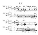
ここで、図1及び図2を参照して、ラック搬送手段の作用を説明する。図2は、供給ライン47における検体ラックの搬送状態を説明したものであるが、他の搬送ラインやバイパスラインでも基本的な搬送動作は同様である。
【0021】
供給ライン47に沿って複数のラック検知器291〜297が配置されており、これらのラック検知器のそれぞれは、供給ライン47上の211〜217の各位置に対応している。すなわち、緊急検体受取り位置211の検体ラックはラック検知器291により検知され、中間位置212に来た検体ラックはラック検知器292により検知され、ラックトレイ152から受取り位置213に押し出された検知ラックはラック検知器293により検知され、ラックトレイ151から受取り位置214に押し出された検体ラックはラック検知器294により検知され、識別情報読取り装置171の読取り位置215に来た検体ラックはラック検知器295により検知され、中間位置216にある検体ラックはラック検知器296により検知され、第1搬送ライン51への引渡し位置217に来た検体ラックはラック検知器297により検知される。
【0022】
ベルト駆動部48は、駆動源に接続された駆動プーリと他のプーリの間に張設された無端ベルトを有し、この無端ベルトにラック移動器310が固定される。ラック移動器310のアームは、所定角度だけ回転でき、図2(A)のように検体ラック2aの後端を押す場合には回転が阻止されるが、図2(C)のように緊急検体投入部のラック検知器291側から第1搬送ライン51への引渡し位置217のラック検知器297側の方へ進められる検体ラックに対してラック移動器310が逆方向に移動する(戻る)場合には、回転自在となり検体ラックに影響を与えずに戻ることができる。図1における他のラック移動器の構成も同様である。
【0023】
今、図2(A)に示すように、ラックトレイ152から受取り位置213に一般検体ラック2aが押し出されたものとすれば、これをラック検知器293で検知したことに伴い、ラック移動器310が一般検体ラック2aの後端を押してラック検知器297の位置まで移動する。これにより、図2(B)の状態になる。この後にラックトレイ352から供給ライン47上に一般検体ラック2bが押し出され、その直後に、緊急検体投入部45に緊急検体ラック2cが投入されたものとする。この場合、ラック検知器293により一般検体ラック2bが検知され、すぐにラック検知器291により緊急検体ラック2cが検知されるので、ラック移動器310は、図2(C)の状態から供給ライン47の始端側へ戻り、緊急検体ラック2cの後端を押して移動させる。さらに、図2(D)に示すように、ラック移動器310は、一般検体ラック2bと緊急検体ラック2cの両方を移動し、一般検体ラック2bがラック検知器294により検知された信号を受けてラック移動器310の押圧動作が停止する。
【0024】
第2の分析ユニット20は、ピペットノズルを有する検体分注装置182と、多数の反応容器が配列された反応ディスク184と、複数の分析項目に対応する試薬ボトルを収容した試薬保冷庫187と、選択した試薬ボトルから反応ディスク184上の反応容器23に試薬液を供給するディスペンシング方式の試薬供給機構185を備える。各反応容器23内で検体と試薬の化学反応又は免疫反応が進行され、反応液の光学的特性が測定される。
【0025】
第3の分析ユニット30は、第2の分析ユニット20とは試薬の供給方式が異なるが、反応液の測定方式は同じである。ピペットノズルを有する検体分注装置183は、バイパスライン31の検体分取位置244にある検体ラックからピペットノズル内に検体の一部を吸入保持し、反応ディスク189上に多数配列された反応容器33の1つにピペットノズル内の検体を吐出する。試薬ターンテーブル188には多数の試薬ボトルが配列されており、試薬ピペットノズルを有する試薬分注機構186により所望の試薬が吸入され、反応容器33内へ吐出される。反応容器内で検体と試薬の反応によって生じた反応液は、反応ディスク189に沿って配置されている光度計により光学的特性が測定され、検体に関連する分析項目の濃度が算出される。
【0026】
第2の分析ユニット20と第3の分析ユニット30は、同様構成のバイパスライン21、31を内蔵する。また、これらの分析ユニット20、30は、移載器371、372、381、382を有する。各分析ユニットへの引渡し位置224、253に来た検体ラックは、移載器371、381によりバイパスライン21、31上のラック受取り位置231、241に移される。また、分注処理後の検体ラックは、各バイパスライン21、31上の引渡し位置236、246から第2搬送ライン52上のラック受取り位置252、254へ移載器372、382により移される。
【0027】
各バイパスライン21、31は、第2搬送ライン52に沿って形成されており、検体ラックを停止させ得る複数の位置を有する。図1の例では、ラック受取り位置231、241識別情報読取り位置232、242、中間位置233、243、検体分取位置234、244、分取完了位置235、245、引渡し位置236、246に検体ラックが停止し得る。中間位置233、243を1つに限らず複数設けることにより検体ラックの収容数を増大できる。
【0028】
バイパスライン21上の検体ラックを移動するために、それぞれにベルト駆動される2つのラック移動器331及び332が配設されており、バイパスライン31上の検体ラックを移動するためには、それぞれにベルト駆動される2つのラック移動器341及び342が配設されている。ラック移動器331、341は、ラック受取り位置から検体分取位置234、244の前段の中間位置233、243までの検体ラックの移動を受け持ち、一方、ラック移動器332、342は、中間位置233、243から引渡し位置236、246までの検体ラックの移動を受け持つ。
【0029】
図1の例では、搬送ラインやバイパスライン上で検体ラックを移動させるための構成としてラック移動器により検体ラックの後端を押す方式を採用しているが、ラック搬送方式としては、これ以外に搬送ライン自体をベルトコンベアで構成するなどの公知の技術を用いることもできる。また、図1の例では、主たる搬送ラインとして第1と第2の搬送ラインを用いているが、主搬送ラインは1本だけにすることもでき、あるいは、各分析ユニット毎に対応する複数の搬送ライン区分により構成することもできる。
【0030】
図1の例では、検体処理ユニットとして3種類の分析ユニットを用いているが、他の検体処理ユニットとして比重差で含有成分を分離させる遠心分離ユニット、蓋が付けられている検体容器の蓋を開けるための開栓ユニット、親検体容器から子検体容器に検体の一部を移すための分注ユニットなどを、一般検体投入部40と第1の分析ユニット10の間に配置し、各ユニットに検体ラックを選択的に搬送する構成にすることもできる。
【0031】
図1において、分析ユニット制御部15は、第1の分析ユニット10の動作制御及び測定データの演算処理を行うコンピュータである。分析ユニット制御部25は、第2の分析ユニット20の動作制御及び測定データの演算処理を行うコンピュータである。分析ユニット制御部35は、第3の分析ユニット30の動作制御及び測定データの演算処理を行うコンピュータである。また、搬送ライン制御部55は、一般検体投入部40、緊急検体投入部45、供給ライン47、第1搬送ライン51、第2搬送ライン52、及びラック収納部60におけるラック検知信号の判断、各ラック移動器の動作、可動レバーの動作、ラック押込み器の動作などの制御により各検体ラックの搬送動作を制御するコンピュータである。さらに、統括制御部70は、3つの分析ユニット制御部及び搬送ライン制御部を統括し、システム全体が円滑に動作するように制御するコンピュータである。
【0032】
統括制御部70に接続された操作部80は、入力部81と操作制御部82と表示部83を有する。入力部81は、キーボードや、表示画面に対するポインティングデバイスとしてのマウスや、タッチパネルなどを包含する。表示部83は、CRTや液晶の画面表示装置の他にプリンタなどの印字装置を有する。
【0033】
容器ホルダーとしての検体ラックの所定部分には、ラック番号やラックの種別を示すラック識別情報(ラックID)が表示されている。また検体ラック2に保持される検体容器の外壁には、収容した検体の番号、処理内容、分析項目などを示す検体識別情報(検体ID)がバーコードの如きマークとして表示されている。図1の例では、ラック識別情報及び検体識別情報がバーコードで表示されているものとする。
【0034】
供給ライン47に沿って配置された識別情報読取装置としてのバーコードリーダ171は、読取り位置215における検体ラックに関しラックID及び/又は検体IDを読み取り、その読み取り結果を搬送ライン制御部55に伝達する。これに基づいて該当検体ラックの処理内容が決定され、検体ラックが立ち寄るように搬送すべき立寄り先の分析ユニット及び各検体に関し分注すべき分析項目名が制御部のメモリに登録される。
【0035】
第2の分析ユニット20のバイパスライン21に沿って識別情報読取装置としてのバーコードリーダ172が配置されており、搬送ラインから受け入れた検体ラックに関しラックID及び/又は検体IDを読み取って分析ユニット制御部25に伝達する。第3の分析ユニット30のバイパスライン31に沿って配置されたバーコードリーダ173は検体ラックに関するID読み取り結果を分析ユニット制御部35に伝達する。尚、統括制御部70、搬送ライン制御部55、分析ユニット制御部15、25、35の全体を包含して制御手段又は制御部と称することがある。
【0036】
次に、図1の実施例における分注処理待ちの検体ラックの停止位置及び待機数について図3及び図4を参照して説明する。
【0037】
一般検体投入部40又は緊急検体投入部45からの検体ラック2は、ラック収納部60に到達するまでの間に、第1の分析ユニット10、第2の分析ユニット20及び第3の分析ユニット30の全部又は選択された一部のユニットに立ち寄ることができる。第1の分析ユニット10では、検体ラック2が識別情報読取り位置215、中間位置216、及び検体分取位置221に停止可能である。第2の分析ユニット20では、検体ラックが引渡し位置224、受取り位置231、識別情報読取り位置232、中間位置233、検体分取位置234などで停止可能である。また、第3の分析ユニット30では、検体ラックが引渡し位置253、受取り位置241、識別情報読取り位置242、中間位置243、検体分取位置244などで停止可能である。
【0038】
各分析ユニットにおける中間位置216、233、243は1個所に限られず、複数箇所にすることができる。分注前の検体ラックを待機させる待機エリアは、第1の分析ユニット10では識別情報読取り位置215及び中間位置216を含み、第2の分析ユニット20ではバイパスライン21上の識別情報読取り位置232及び中間位置233を含み、第3の分析ユニット30ではバイパスライン31上の識別情報読取り位置242及び中間位置243を含む。
【0039】
一般処理対応モードのときは、供給ライン47上の受取り位置213及び214に一般検体投入部40からの検体ラックを押し出すことができ、供給ライン47は緊急検体投入部45からの検体ラックを受け入れることができる。一般処理対応モードでは、各分析ユニットにおける分注前の待機エリアに該当するラック停止可能位置の全位置が待機可能位置として、対応する各ラック検知器により監視され、ラック移動器320、331、341はそれら全位置に検体ラックを位置づけることができる。模式図である図3の例では、待機エリアにおける待機可能な検体ラック数が、第1の分析ユニット10では2個であり、第2の分析ユニット20では2個であり、第3の分析ユニットでは2個であるが、各中間位置の数を増やすことによりこのような待機エリアにおける所定数の収容可能な検体ラック数を大きく設定でき、分析ユニット同士の待機可能な所定数を互いに異なる数に設定することができる。
【0040】
緊急処理対応モードでは、上述した一般処理対応モードのときの待機エリアにおける所定数の収容可能な検体ラック数よりも少ない数となるように、各分析ユニット10、20、30の待機エリアにおける待機可能な検体ラック数が制限される。すなわち、第1の分析ユニット10における中間216(図4のマーク参照)には検体ラックが停止されないように、ラック移動器320の如きラック搬送手段の動作が制御部により制御される。具体的には、識別情報読取り位置215にてラックID及び検体IDを読み取られた検体ラック2が、中間位置216をスキップして検体分取位置221に停止するようにラック移動器320の動作が制御される。
【0041】
また、第2及び第3の分析ユニット20、30における中間位置233、243には検体ラックが停止されないように、各分析ユニットのラック移動器331、341の動作が制御部により制御される。具体的には、識別情報読取り位置232、242にて停止していた検体ラックが、中間位置233、243をスキップして検体分取位置234、244に位置づけられる。
【0042】
緊急処理対応モードのときは、各分析ユニットの待機エリアにおける待機可能な検体ラック数又は分析項目数の制限条件を、複数レベル(複数段階)が存在するように制御部に設定しておき、必要に応じて適正なレベルを選択するように構成できる。例えば、緊急処理対応モードにおける緩やかなレベルでは、上述したように、それぞれの分析ユニットにおける検体ラックの待機位置を、一般処理対応モードのときの所定数より1個所ずつ減少させる。中程度のレベルでは、該所定数より待機位置を2個所減少させる。最も厳しいレベルでは、各分析ユニットの待機エリアに一切の検体ラックを待機させず、一般検体投入部40から供給ライン47への一般検体ラックの送り出し動作を一時停止させ、緊急検体投入部45からの緊急検体ラックが一般検体ラックの存在によって進路が妨げられることなく検体分取位置に搬送されるように制御できる。
【0043】
例えば、第2の分析ユニット20において、バイパスライン21上の待機エリアに、一般処理対応モードのときは2個所の中間位置と1個所の識別情報読取り位置が存在すると想定すれば、一般処理対応モードのときの待機可能な所定数は、検体ラックとして3個である。これに対し、緊急処理対応モードでは、緩やかなレベルのときの待機可能な検体ラック数は1つの中間位置をスキップさせる2個となり、中程度のレベルのときの待機可能な検体ラック数は2つの中間位置をスキップさせる1個となり、厳しいレベルのときの待機可能な検体ラック数は、識別情報読取り位置をもスキップされるのでゼロとなる。
【0044】
検体処理システムを一般処理対応モードで稼動している途中で、緊急処理対応モードの処理動作に変更すること、及びその逆の変更を実行させることは、図1の操作部80から指示できる。この場合、操作部80は、各モードの適用を指示する指示装置として機能する。
【0045】
図5は、各分析ユニット毎に処理モードを選択的に指示する態様を説明するための図であって、表示部83の画面表示装置に処理モード設定画面の1つを表示させた例である。モード設定画面85には、レベル表示欄201及び分析ユニットを選択するための詳細設定欄が表示される。図5の例では、電解質分析ユニットと化学分析ユニット1のチェックボックスにユニット指示マークがなく、化学分析ユニット2のチェックボックスにはユニット指示マーク202が表示されている。これは、化学分析ユニット2(図1の例における第3の分析ユニット30に相当)だけに緊急処理対応モードを適用するように指示した結果であり、他の分析ユニットは一般処理対応モードを適用することを指示している。このように各分析ユニットは個別にモード選択できる。
【0046】
図5において、レベル表示欄201はレベル指示ボタン5a及び5bを有し、いずれの分析ユニットにもユニット指示マーク202による指示がない場合には、可動子5cはレベル指示ボタン5bに最も接近した側に位置する。つまり、全分析ユニットが一般処理対応モード状態で動作していることを示す。可動子5cの位置はレベル指示ボタン5a、5bの操作により複数段階に変えることができ、指示ボタン5aをクリックすれば左動し指示ボタン5bをクリックすれば右動する。可動子5cが指示ボタン5bに最接近した位置以外にあるときは、緊急処理対応モードが適用されおり、しかも、可動子5cの位置がレベル指示ボタン5aに近い状態になるにつれて、分析ユニットの待機エリアにおける待機可能な検体ラック数又は分析項目数を制限する程度が厳しいレベルであることを示す。
【0047】
可動子5cの位置情報は制御部によって認識され、指示に対応する分析ユニットの待機エリアにおける待機可能な検体ラック数又は分析項目数の制限条件が、可動子5cの位置に応じてレベル設定される。図5の例では、1つの分析ユニットだけに緊急処理対応モードを適用しているが、2つ以上の分析ユニットあるいは全部の分析ユニットに緊急処理対応モードを適用できる。また、モード設定画面85を多少変更して、分析ユニット毎に対応するレベル表示欄を設けることにより、分析ユニット同士をレベルの異なる緊急処理対応モードで動作するように構成することもできる。このように、図5におけるレベル表示欄201は、緊急処理対応モードの際の待機可能レベルを調整又は選択する手段として機能する。
【0048】
図6は、処理モード指示装置における処理モード設定画面の他の例を説明するための図である。モード設定画面86は、複数の時間帯を示す時間帯表示欄203a、203b、203c、203dと、各時間帯にそれぞれ対応するように形成された複数のレベル表示欄、201a、201b、201c、201dと、検体処理システムに配置されており分注前の検体ラックを待機させる待機エリアを備えた分析ユニットが示された詳細設定欄を表示する。各レベル表示欄は、レベル指示ボタンと可動子を有し、図5の場合と同様のレベル調整又は選択の機能を有する。各分析ユニットに対し緊急処理対応モードを適用するか又は一般処理対応モードを適用するかの指示方法は、図5の場合と同様である。
【0049】
図6の例では、1日を4つの時間帯に区分し、各時間帯に応じて分析ユニットの待機エリアにて待機可能な検体ラック数又は分析項目数に対応するレベルが調整又は選択される。図6では、時間帯別の処理モードの選択と緊急検体処理モードにおけるレベルを選択し得るように構成されているが、さらに一週間を曜日毎に区分して、各曜日のレベル調整を実行できるように構成してもよい。図6では、9時から12時までの時間帯が病院における外来患者に由来の多数の検体を処理する都合上、一般処理対応モードで稼動される。12時から16時までの時間帯は入院患者由来の検体が多いので、緊急処理対応モードの内のスキップ数の少ない緩やかなレベルで稼動される。16時から0時までの時間帯及び0時から9時までの時間帯は、緊急患者に由来の緊急検体の処理が主となるので、緊急処理対応モードのうちの厳しいレベルで稼動される。
【0050】
図1の操作部80からオペレータが処理モードを指示する代りに、モード切り替えを自動的に実行することも可能である。この場合、検体処理システムは、病院内の上位ホストコンピュータと通信接続されており、診療室などの検体検査依頼元の操作装置がホイストコンピュータに接続されている。図7は、診療室の操作装置における緊急検体の依頼予告の画面の例を示したものである。
【0051】
図7において、入力画面87は、検体の検査依頼をする部署の入力欄301a,患者IDの入力欄301b,患者氏名の入力欄301c,検体種別(材料)の入力欄301d,依頼項目の入力欄301e,依頼時刻入力欄301f,結果要求入力欄301g,報告希望の予定時刻の入力欄301hなどを有する。また、入力画面87は、検査依頼送信ボタン302,処理モードの詳細設定関連のボタン303,304,条件変更ボタン305,取消ボタン306などを有する。各入力欄に必要事項を入力した後、検査依頼送信ボタン302を操作すると、検体処理システムの統括制御部に対して緊急検体の処理の依頼予告がなされる。制御部は、このような依頼予告情報に基づいて、緊急検体を有する検体ラックが投入されることに備えて、各分析ユニットの処理モードを一般処理対応モードから緊急処理対応モードに変更する。
【0052】
次に、図8及び図9を参照して本発明の他の実施例を説明する。図8における複数の分析ユニットの内、第1の分析ユニット100aは電解質成分を分析測定し、第2の分析ユニット100b及び第3の分析ユニット100cは分析項目を化学分析する。図1の実施例と同じ符号を付してある部分は同じ機能を有する。また、図8では、制御系が図1の例と同じ構成であるので、表示を省略してある。図8の例が図1の場合と相違する点は、第2及び第3の分析ユニットがバイパスラインを具備していない点と、再検バッファ部90及び戻りライン95を有する点である。
【0053】
各分析ユニットは、主搬送ライン57上に分注前の検体ラックを待機させる待機エリアを有し、主搬送ライン57上の検体分取位置221a,221b,221c上の検体ラックから測定部の方へ、検体分注装置181,182,183により検体の一部が分取される。分注処理の終了した検体ラックは、測定データが得られるまで再検バッファ部90内に一時的に格納され、測定の結果が問題ないときはラック収納部60へ移されるが、測定結果に異常の可能性があるときはラック振分け機構92を介して戻りライン95に引渡される。戻りライン95を搬送されて供給ライン47に戻された検体ラックは、主搬送ライン57により所望の分析ユニットへ搬送され、再度の分注処理を受ける。
【0054】
図9に示すように、各分析ユニットは、検体分取位置221a,221b,221cの前段に、識別情報読取り位置215a,215b,215c及び中間位置216a,216b,216cなどを有しており、これらが分注前の検体ラックを待機させる待機エリアを形成している。この実施例においても、一般処理対応モードでは、待機エリア内の全部のラック停止位置が所定数の待機位置として機能する。しかしながら、緊急処理対応モードでは、それらの停止位置の内の一部又は全部が待機位置から除外され、検体ラックがスキップされることは、図1の実施例の場合と同様である。
【0055】
各分析ユニットの待機エリアにおける待機検体に関し制御部によって監視される対象は、図1及び図8の各実施例のような検体ラック数又は分析項目数だけに限られない。待機エリアにて待機可能の程度を制限する監視対象は、待機エリアにおける最後尾の検体までに要する最大分注予定回数であってもよく、あるいは、待機エリアにおける最後尾の検体までの最長の分注処理待ち時間であってもよい。いずれにしても、緊急処理対応モードのときは、最大分注予定回数又は最大分注処理待ち時間に関する許容値が、一般処理対応モードのときよりも小さい値であるように制御部によって設定され、新たに投入された緊急検体が検体処理ユニットにより分注処理を受けるまでの時間が、一般処理対応モードのときよりも短縮されるように構成される。
【0056】
【発明の効果】
本発明によれば、一般処理対応モードにて検体を処理することによって多数の検体を効率的に連続処理でき、緊急処理対応モードにて検体を処理することによって特に緊急な処理が必要とされる検体の処理待ち時間を少なくできる。
【図面の簡単な説明】
【図1】本発明の一実施例の構成を示す概略平面図である。
【図2】図1の実施例における検体ラックの搬送状態を説明するための図である。
【図3】一般処理対応モードにおける検体ラック停止位置の説明図である。
【図4】緊急処理対応モードにおける検体ラック待機位置の説明図である。
【図5】指示装置の処理モード設定画面の一例を示す図である。
【図6】指示装置の処理モード設定画面の他の例を示す図である。
【図7】検体検査依頼元の操作装置における緊急検体の依頼予告の画面例を示す図である。
【図8】本発明の他の実施例の構成を示す平面図である。
【図9】図8の実施例における各分析ユニットの検体ラック停止位置を説明するための図である。
【符号の説明】
2…検体ラック、10,20,30…分析ユニット、21,31…バイパスライン、40…一般検体投入部、45…緊急検体投入部、47…供給ライン、51…第1搬送ライン、52…第2搬送ライン、57…主搬送ライン、60…ラック収納部、61…収納ライン、70…統括制御部、80…操作部、100a,100b,100c…分析ユニット、181,182,183…検体分注装置、215,215a,215b,215c,232,242…識別情報読取り装置、216,216a,216b,233,243…中間位置、221,221a,221b,221c,234,244…検体分取位置。[0001]
TECHNICAL FIELD OF THE INVENTION
The present invention relates to a sample processing system, and more particularly to a sample processing system that performs physical processing or chemical processing using a biological sample such as blood or urine as a sample.
[0002]
[Prior art]
When analyzing a large number of specimens composed of biological samples such as blood and urine, specimen containers containing specimens are often handled in a state of being held by a holder called a specimen rack. There are roughly two types of methods for sorting the samples held in such a sample rack into an analysis unit having an analytical measurement function.
[0003]
For example, as disclosed in Japanese Patent Laid-Open No. 3-285175, the sample rack is stopped in the middle of transporting the sample rack from the rack supply unit to the rack storage unit, and the sample on the transport line is used. In this method, a sample is dispensed from a rack to a reaction container in an analysis unit using a pipettor.
[0004]
The other one is, for example, as shown in Japanese Patent Laid-Open No. 9-281113, in the analysis unit arranged along the main transport line, a bypass line for the main transport line is formed and transported by the main transport line The sample rack is transferred to the bypass line and then the sample is dispensed from the sample rack on the bypass line to the reaction container of the analysis unit using a dispenser.
[0005]
[Problems to be solved by the invention]
In order to efficiently process a large number of samples by a centrifuge unit, a sample processing unit such as a parent sample-to-child sample dispensing unit, an analysis unit, etc., by supplying a sample rack with samples to the processing position without interruption It is desirable that the sample processing unit is configured not to cause a sample waiting state. For this purpose, a standby area for waiting a plurality of sample racks in the vicinity of the dispensing position to the analysis unit is provided, and when dispensing of the sample on the preceding sample rack is completed at the dispensing position. A method of immediately positioning the next sample rack from the waiting area at the dispensing position is effective.
[0006]
However, with such a configuration in which a standby area is provided, even when a sample that must be analyzed urgently is requested, a large number of general samples waiting for a dispensing process on the standby area are processed. Otherwise, there arises a problem that the urgent sample cannot be processed. That is, in the case of the type as disclosed in Japanese Patent Laid-Open No. 3-285175, a number of sample racks are already waiting for processing on the transport line before the start of transport of the emergency sample. In the case of this type, a large number of sample racks are already waiting to be processed on the bypass line before the emergency sample transport starts, so that the result of processing the emergency sample can be obtained within a short time. I can't.
[0007]
An object of the present invention is to provide a sample processing system that can efficiently perform continuous processing on a large number of samples, and can reduce the processing waiting time especially when processing samples that require an emergency.
[0008]
[Means for Solving the Problems]
A sample processing unit in a sample processing system to which the present invention is applied includes a sample dispensing device for dispensing a sample from a sample rack. A sample rack from a general sample loading unit into which a sample rack having a general sample is loaded or an emergency sample loading unit into which a sample rack having an urgent sample is loaded is transported to a sample processing unit by a rack transporting unit. The waiting area for waiting for the sample rack before dispensing is formed between the general sample input unit and the sample processing unit, or formed in a bypass line in the sample processing unit.
[0009]
In the general processing support mode, the sample processing unit or the rack transport means is controlled so that the number of sample racks or analysis items that can be standby is a predetermined number in the standby area, and in the emergency processing support mode, The sample processing unit or the rack transport means is controlled so that the number of sample racks or analysis items that can be waited for is less than the predetermined number.
[0010]
In addition to the number of sample racks and the number of analysis items, the monitoring target in the waiting area may be the maximum scheduled dispensing number or the longest dispensing waiting time. When an emergency sample is scheduled to be processed, the mode is changed from the general processing support mode to the emergency processing support mode, and the emergency processing support mode is limited so that the number of standbys or the standby time becomes smaller.
[0011]
In a preferred embodiment according to the present invention, a plurality of sample processing units are arranged, and each of the sample processing units has an instruction device for instructing that an emergency processing support mode can be applied. In the emergency processing mode, the number of standbys (number of sample racks, number of analysis items, maximum number of scheduled dispenses, etc.) and standby time can be changed to multiple levels, and the desired level is selected or adjusted by the pointing device can do. Further, the day or operation time can be divided into a plurality of time zones, and the level of the emergency processing support mode can be selected or adjusted for each time zone. Such level selection or adjustment is preferably performed through a screen display device included in the pointing device.
[0012]
DETAILED DESCRIPTION OF THE INVENTION
A configuration of a sample processing system according to an embodiment of the present invention will be described with reference to FIGS.
[0013]
Two
[0014]
The sample rack loaded into the general
[0015]
In the system of FIG. 1, three types of analysis units are arranged as sample processing units between the general
[0016]
The
[0017]
The
[0018]
A rack transfer means is formed by the
[0019]
The second transport line 52 includes a rack receiving position 251 for receiving the
[0020]
Here, the operation of the rack transport means will be described with reference to FIGS. FIG. 2 illustrates the transport state of the sample rack in the
[0021]
A plurality of
[0022]
The
[0023]
As shown in FIG. 2A, if the
[0024]
The
[0025]
The
[0026]
The
[0027]
Each of the
[0028]
In order to move the sample rack on the
[0029]
In the example of FIG. 1, a method of pushing the rear end of the sample rack with a rack mover is adopted as a configuration for moving the sample rack on the transfer line or bypass line. It is also possible to use a known technique such as configuring the transport line itself with a belt conveyor. In addition, in the example of FIG. 1, the first and second transport lines are used as the main transport lines, but the main transport line can be only one, or a plurality of corresponding ones for each analysis unit. It can also be configured by a conveyance line section.
[0030]
In the example of FIG. 1, three types of analysis units are used as the sample processing unit, but as another sample processing unit, a centrifuge unit that separates components by specific gravity difference, and a sample container lid that is provided with a lid. An opening unit for opening, a dispensing unit for transferring a part of the sample from the parent sample container to the child sample container, and the like are arranged between the general
[0031]
In FIG. 1, an analysis
[0032]
The
[0033]
Rack identification information (rack ID) indicating a rack number and a rack type is displayed on a predetermined portion of the sample rack as the container holder. On the outer wall of the sample container held in the
[0034]
The
[0035]
A
[0036]
Next, the stop position and the waiting number of the sample rack waiting for the dispensing process in the embodiment of FIG. 1 will be described with reference to FIGS.
[0037]
The
[0038]
The
[0039]
In the general processing support mode, the sample rack from the general
[0040]
In the emergency processing response mode, standby is possible in the standby area of each
[0041]
The operation of the rack movers 331 and 341 of each analysis unit is controlled by the control unit so that the sample rack is not stopped at the
[0042]
In the emergency processing mode, the restriction conditions for the number of sample racks or analysis items that can be waited in the waiting area of each analysis unit are set in the control unit so that there are multiple levels (multiple stages). It is possible to configure so as to select an appropriate level according to the above. For example, at a moderate level in the emergency processing support mode, as described above, the standby position of the sample rack in each analysis unit is decreased by one from the predetermined number in the general processing support mode. At an intermediate level, the standby position is reduced by two places from the predetermined number. At the strictest level, no sample racks are kept waiting in the standby area of each analysis unit, the delivery operation of the general sample racks from the general
[0043]
For example, in the
[0044]
It can be instructed from the
[0045]
FIG. 5 is a diagram for explaining a mode for selectively instructing the processing mode for each analysis unit, and is an example in which one of the processing mode setting screens is displayed on the screen display device of the
[0046]
In FIG. 5, the
[0047]
The position information of the
[0048]
FIG. 6 is a diagram for explaining another example of the processing mode setting screen in the processing mode instruction apparatus. The
[0049]
In the example of FIG. 6, one day is divided into four time zones, and the level corresponding to the number of sample racks or analysis items that can be waited in the standby area of the analysis unit is adjusted or selected according to each time zone. . In FIG. 6, the processing mode is selected according to the time zone and the level in the emergency sample processing mode can be selected. However, the level can be adjusted for each day of the week by further dividing the week into days of the week. You may comprise as follows. In FIG. 6, the time zone from 9 o'clock to 12 o'clock is operated in the general processing support mode for the convenience of processing a large number of specimens derived from outpatients in the hospital. In the time period from 12:00 to 16:00, there are many inpatient-derived specimens, so the operation is performed at a moderate level with a small number of skips in the emergency processing support mode. In the time zone from 16:00 to 0 o'clock and the time zone from 0 o'clock to 9 o'clock, the emergency specimen derived from the emergency patient is mainly processed, so that the operation is performed at a severe level in the emergency processing support mode.
[0050]
Instead of the operator instructing the processing mode from the
[0051]
In FIG. 7, an
[0052]
Next, another embodiment of the present invention will be described with reference to FIGS. Of the plurality of analysis units in FIG. 8, the
[0053]
Each analysis unit has a standby area for waiting for a sample rack before dispensing on the
[0054]
As shown in FIG. 9, each analysis unit has identification
[0055]
The target monitored by the control unit regarding the standby sample in the standby area of each analysis unit is not limited to the number of sample racks or the number of analysis items as in the embodiments of FIGS. The monitoring target that limits the degree of waiting in the waiting area may be the maximum scheduled number of dispensings required until the last sample in the waiting area, or the longest minute until the last sample in the waiting area. It may be a note processing waiting time. In any case, when in the emergency processing support mode, the control unit sets the allowable value for the maximum number of scheduled dispensing times or the maximum dispensing processing waiting time to be a smaller value than in the general processing support mode, The time until the newly loaded emergency sample is subjected to the dispensing process by the sample processing unit is configured to be shorter than that in the general processing support mode.
[0056]
【The invention's effect】
According to the present invention, it is possible to efficiently and continuously process a large number of samples by processing samples in the general processing mode, and particularly urgent processing is required by processing samples in the emergency processing mode. The waiting time for sample processing can be reduced.
[Brief description of the drawings]
FIG. 1 is a schematic plan view showing the configuration of an embodiment of the present invention.
FIG. 2 is a diagram for explaining a transport state of a sample rack in the embodiment of FIG.
FIG. 3 is an explanatory diagram of a sample rack stop position in a general processing support mode.
FIG. 4 is an explanatory diagram of a sample rack standby position in an emergency processing response mode.
FIG. 5 is a diagram illustrating an example of a processing mode setting screen of the pointing device.
FIG. 6 is a diagram showing another example of the processing mode setting screen of the pointing device.
FIG. 7 is a diagram illustrating an example of a screen for requesting an emergency sample request on the operation device that is a sample test request source.
FIG. 8 is a plan view showing the configuration of another embodiment of the present invention.
FIG. 9 is a diagram for explaining a sample rack stop position of each analysis unit in the embodiment of FIG. 8;
[Explanation of symbols]
2 ... Sample rack, 10, 20, 30 ... Analysis unit, 21,31 ... Bypass line, 40 ... General sample input unit, 45 ... Emergency sample input unit, 47 ... Supply line, 51 ... First transport line, 52 ... No. 2 transport lines, 57 ... main transport line, 60 ... rack storage unit, 61 ... storage line, 70 ... overall control unit, 80 ... operating unit, 100a, 100b, 100c ... analysis unit, 181,182,183 ... sample dispensing Device, 215, 215a, 215b, 215c, 232, 242 ... identification information reading device, 216, 216a, 216b, 233, 243 ... intermediate position, 221, 221a, 221b, 221c, 234, 244 ... specimen collection position.
Claims (7)
Translated fromJapanese一般検体を有する検体ラックが投入される一般検体投入部と、
緊急検体を有する検体ラックが投入される緊急検体投入部と、
上記一般検体投入部又は上記緊急検体投入部からの検体ラックを上記検体処理ユニットへ搬送するラック搬送手段とを備えた検体処理システムにおいて、
一般処理対応モードでは、上記待機エリアにおける待機可能な検体ラック数又は分析項目数が所定数であるように上記検体処理ユニットを制御し、緊急処理対応モードでは、上記待機エリアにおける待機可能な検体ラック数又は分析項目数を上記所定数より少なくするように上記検体処理ユニットを制御する制御手段を備え、
かつ前記制御手段は、区分された時間帯毎に予め上記緊急処理対応モードを設定できることを特徴とする検体処理システム。A sample processing unit having a waiting area for waiting for a sample dispensing device and a sample rack before dispensing;
A general sample loading unit into which a sample rack having a general sample is loaded;
An emergency sample loading unit into which a sample rack having an emergency sample is loaded;
In a sample processing system comprising a rack transport means for transporting a sample rack from the general sample input unit or the emergency sample input unit to the sample processing unit,
In the general processing support mode, the sample processing unit is controlled so that the number of sample racks or analysis items that can be standby in the standby area is a predetermined number, and in the emergencyprocessing support mode, the sample racks that can be standby in the standby area. Control means for controlling the sample processing unit so that the number or the number of analysis items is less than the predetermined number,
The sample processing system is characterized in that thecontrol means can set the emergencyprocessing mode inadvance for eachdivided timezone .
一般検体を有する検体ラックが投入される一般検体投入部と、
緊急検体を有する検体ラックが投入される緊急検体投入部と、
上記一般検体投入部又は上記緊急検体投入部からの検体ラックを上記検体処理ユニットへ搬送するラック搬送手段とを備えた検体処理システムにおいて、
一般処理対応モードでは、上記待機エリアにおける待機可能な検体ラック数又は分析項目数が所定数であるように上記検体処理ユニットを制御し、緊急処理対応モードでは、上記待機エリアにおける待機可能な検体ラック数又は分析項目数を上記所定数より少なくするように上記検体処理ユニットを制御する制御手段を備え、
かつ前記制御手段は、緊急検体を有する検体ラックの、装置への投入に先立つ緊急検体の処理依頼予告情報に基づいて、予め上記緊急処理対応モードに切り換える機能を備えたことを特徴とする検体処理システム。A sample processing unit having a waiting area for waiting for a sample dispensing device and a sample rack before dispensing;
A general sample loading unit into which a sample rack having a general sample is loaded;
An emergency sample loading unit into which a sample rack having an emergency sample is loaded;
In a sample processing system comprising a rack transport means for transporting a sample rack from the general sample input unit or the emergency sample input unit to the sample processing unit,
In the general processing support mode, the sample processing unit is controlled so that the number of sample racks or analysis items that can be standby in the standby area is a predetermined number, and in the emergencyprocessing support mode, the sample racks that can be standby in the standby area. Control means for controlling the sample processing unit so that the number or the number of analysis items is less than the predetermined number,
In addition, thecontrol means includes a function of previously switching to the emergencyprocessing support mode based on the emergency sample processing request advance notice information prior to loading the sample rack havingthe emergency sample into the apparatus. system.
上記ラック搬送手段によって検体ラックが搬送される検体処理ユニットを複数設け、上記緊急処理対応モードをいずれの検体処理ユニットに適用するかを指示するための指示装置を設けたことを特徴とする検体処理システム。The sample processing system according to claim 1or 2 ,
A sample processing system comprising a plurality of sample processing units for transporting sample racks by the rack transport means, and an instruction device for instructing to which sample processing unit the emergency processing support mode is applied system.
上記指示装置は、上記緊急処理対応モードの際の待機可能な検体ラック数又は分析項目数に対応するレベルを調整するための調整手段を有することを特徴とする検体処理システム。The specimen processing system according to claim3 , wherein
The sample processing system, wherein the instruction device includes an adjusting unit for adjusting a level corresponding to the number of sample racks or analysis items that can be on standby in the emergency processing support mode.
上記指示装置は、上記レベルを表示するための画面表示装置を有することを特徴とする検体処理システム。The specimen processing system according to claim4 ,
The sample processing system, wherein the instruction device includes a screen display device for displaying the level.
一般処理対応モードでは、上記待機エリアにおける待機可能な検体ラック数又は分析項目数が所定数であるように上記検体処理ユニットを制御し、緊急処理対応モードでは、上記待機エリアにおける待機可能な検体ラック数又は分析項目数を上記所定数より少なくするように上記検体処理ユニットを制御する制御手段を備え、
上記ラック搬送手段によって検体ラックが搬送される検体処理ユニットを複数設け、上記緊急処理対応モードをいずれの検体処理ユニットに適用するかを指示するための指示装置を設け、かつ
上記指示装置は、複数の時間帯のそれぞれに対し待機可能な検体ラック数又は分析項目数に対応するレベルを調整するための調整手段を有することを特徴とする検体処理システム。A sample processing unit having a waiting area for waiting for a sample dispensing device and a sample rack before dispensing, a general sample loading unit for loading a sample rack having a general sample, and a sample rack having an urgent sample are loaded In a sample processing system comprising an emergency sample input unit, and a rack transport means for transporting a sample rack from the general sample input unit or the emergency sample input unit to the sample processing unit,
In the general processing support mode, the sample processing unit is controlled so that the number of sample racks or analysis items that can be standby in the standby area is a predetermined number, and in the emergency processing support mode, the sample racks that can be standby in the standby area. Control means for controlling the sample processing unit so that the number or the number of analysis items is less than the predetermined number,
There are provided a plurality of sample processing units for transporting the sample rack by the rack transport means, an instruction device for instructing to which sample processing unit the emergency processing response mode is applied, and the instruction device includes a plurality of sample processing units. A sample processing system comprising an adjusting means for adjusting a level corresponding to the number of sample racks or analysis items that can stand by for each of the time periods.
上記指示装置は、上記制御手段に対する検体検査要求元からの緊急検体の処理の依頼予告情報に基づいて上記一般処理対応モードを上記緊急処理対応モードに変更するものであることを特徴とする検体処理システム。The specimen processing system according to claim6 , wherein
The sample processing is characterized in that the instruction device changes the general processing support mode to the emergency processing support mode on the basis of request information for requesting an emergency sample processing from a sample test request source to the control means. system.
Priority Applications (2)
| Application Number | Priority Date | Filing Date | Title |
|---|---|---|---|
| JP21770498AJP3930977B2 (en) | 1998-07-31 | 1998-07-31 | Sample processing system |
| US09/364,061US6444171B1 (en) | 1998-07-31 | 1999-07-30 | Sample processing system |
Applications Claiming Priority (1)
| Application Number | Priority Date | Filing Date | Title |
|---|---|---|---|
| JP21770498AJP3930977B2 (en) | 1998-07-31 | 1998-07-31 | Sample processing system |
Publications (2)
| Publication Number | Publication Date |
|---|---|
| JP2000046842A JP2000046842A (en) | 2000-02-18 |
| JP3930977B2true JP3930977B2 (en) | 2007-06-13 |
Family
ID=16708437
Family Applications (1)
| Application Number | Title | Priority Date | Filing Date |
|---|---|---|---|
| JP21770498AExpired - LifetimeJP3930977B2 (en) | 1998-07-31 | 1998-07-31 | Sample processing system |
Country Status (2)
| Country | Link |
|---|---|
| US (1) | US6444171B1 (en) |
| JP (1) | JP3930977B2 (en) |
Cited By (2)
| Publication number | Priority date | Publication date | Assignee | Title |
|---|---|---|---|---|
| JP2012141149A (en)* | 2010-12-28 | 2012-07-26 | Sysmex Corp | Specimen processing system |
| WO2014203663A1 (en) | 2013-06-17 | 2014-12-24 | 株式会社 日立ハイテクノロジーズ | Automatic analysis device |
Families Citing this family (117)
| Publication number | Priority date | Publication date | Assignee | Title |
|---|---|---|---|---|
| JP2988362B2 (en)* | 1996-03-11 | 1999-12-13 | 株式会社日立製作所 | Multi-sample analysis system |
| US6899848B1 (en)* | 2001-02-27 | 2005-05-31 | Hamilton Company | Automated sample treatment system: apparatus and method |
| US7458483B2 (en) | 2001-04-24 | 2008-12-02 | Abbott Laboratories, Inc. | Assay testing diagnostic analyzer |
| US6588625B2 (en)* | 2001-04-24 | 2003-07-08 | Abbott Laboratories | Sample handling system |
| US6790413B2 (en)* | 2001-05-03 | 2004-09-14 | Beckman Coulter, Inc. | Sample presentation unit |
| US20020168292A1 (en)* | 2001-05-14 | 2002-11-14 | Whisenhunt Donald Wayne | Systems and methods for the high throughput preparation and analysis of chemical reactions |
| JP3829666B2 (en)* | 2001-08-21 | 2006-10-04 | 株式会社日立製作所 | Automated analysis system for biological samples |
| US7514270B2 (en) | 2002-04-12 | 2009-04-07 | Instrumentation Laboratory Company | Immunoassay probe |
| US7380654B2 (en)* | 2002-07-26 | 2008-06-03 | Abbott Laboratories | Conveyor track drive |
| JP2004061456A (en)* | 2002-07-31 | 2004-02-26 | Teruaki Ito | Specimen pretreatment carrying system |
| JP3765788B2 (en)* | 2002-11-29 | 2006-04-12 | 照明 伊藤 | Sample dispensing system |
| US7000785B2 (en)* | 2003-04-03 | 2006-02-21 | Bio-Rad Laboratories, Inc. | Tube rack accommodating a range of tube diameters |
| JP4355590B2 (en)* | 2004-02-23 | 2009-11-04 | シスメックス株式会社 | Analysis system |
| WO2005093434A1 (en)* | 2004-03-05 | 2005-10-06 | Beckman Coulter, Inc. | Magnetic specimen-transport system for automated clinical instrument |
| US7850914B2 (en)* | 2004-03-05 | 2010-12-14 | Beckman Coulter, Inc. | Specimen-transport module for a multi-instrument clinical workcell |
| US8211386B2 (en) | 2004-06-08 | 2012-07-03 | Biokit, S.A. | Tapered cuvette and method of collecting magnetic particles |
| ES2303014T3 (en) | 2004-11-25 | 2008-08-01 | F. Hoffmann-La Roche Ag | DEVICE FOR THE SAMPLE ANALYSIS. |
| JP4546863B2 (en)* | 2005-03-28 | 2010-09-22 | シスメックス株式会社 | Transport device |
| US7628954B2 (en) | 2005-05-04 | 2009-12-08 | Abbott Laboratories, Inc. | Reagent and sample handling device for automatic testing system |
| WO2007095366A2 (en)* | 2006-02-13 | 2007-08-23 | The Johns Hopkins University | System and methods for sampling materials |
| JP4740797B2 (en)* | 2006-05-31 | 2011-08-03 | ベックマン コールター, インコーポレイテッド | Analysis device, communication method, and communication program |
| JP2007322287A (en)* | 2006-06-01 | 2007-12-13 | Olympus Corp | Autoanalyer |
| JP5063999B2 (en)* | 2006-11-30 | 2012-10-31 | シスメックス株式会社 | Blood image analyzer |
| JP4500822B2 (en)* | 2007-02-19 | 2010-07-14 | 株式会社日立ハイテクノロジーズ | Automatic analyzer |
| EP2135141A4 (en)* | 2007-02-26 | 2011-12-28 | Groupe Gecko Alliance Inc | A method, device and system for use in configuring a bathing unit controller |
| JP2008209332A (en)* | 2007-02-28 | 2008-09-11 | Hitachi High-Technologies Corp | Automatic analyzer |
| JP4945342B2 (en)* | 2007-06-28 | 2012-06-06 | 株式会社日立ハイテクノロジーズ | Automatic analyzer and dispensing method of automatic analyzer |
| JP5479672B2 (en)* | 2007-09-27 | 2014-04-23 | シスメックス株式会社 | Blood or urine analyzer and data processor |
| EP2098869B1 (en) | 2008-03-07 | 2022-07-20 | Sysmex Corporation | Analyzer and sample transportation method for analyzer |
| JP5216408B2 (en)* | 2008-05-08 | 2013-06-19 | 株式会社日立ハイテクノロジーズ | Automatic analysis system |
| JP5530613B2 (en)* | 2008-10-06 | 2014-06-25 | シスメックス株式会社 | Sample processing system and sample transport system |
| JP5339853B2 (en)* | 2008-10-30 | 2013-11-13 | シスメックス株式会社 | Sample processing system |
| JP5513040B2 (en)* | 2009-08-28 | 2014-06-04 | シスメックス株式会社 | Automatic analyzer |
| JP5496581B2 (en)* | 2009-08-31 | 2014-05-21 | シスメックス株式会社 | Sample processing equipment |
| US9291633B2 (en)* | 2009-09-30 | 2016-03-22 | Hitachi High-Technologies Corporation | Automated sample processing system |
| DE102010028769A1 (en) | 2010-05-07 | 2011-11-10 | Pvt Probenverteiltechnik Gmbh | System for transporting containers between different stations and container carriers |
| CN103675303B (en) | 2010-07-23 | 2016-02-03 | 贝克曼考尔特公司 | Sensing system |
| CN103748472B (en)* | 2011-09-05 | 2016-08-17 | 株式会社日立高新技术 | Automatic analysis device |
| EP2589966A1 (en) | 2011-11-04 | 2013-05-08 | Roche Diagnostics GmbH | Laboratory sample distribution system and corresponding method of operation |
| EP2589967A1 (en) | 2011-11-04 | 2013-05-08 | Roche Diagnostics GmbH | Laboratory sample distribution system and corresponding method of operation |
| EP2589968A1 (en) | 2011-11-04 | 2013-05-08 | Roche Diagnostics GmbH | Laboratory sample distribution system, laboratory system and method of operating |
| KR20140091032A (en) | 2011-11-07 | 2014-07-18 | 베크만 컬터, 인코포레이티드 | Magnetic damping for specimen transport system |
| BR112014010955A2 (en)* | 2011-11-07 | 2017-06-06 | Beckman Coulter Inc | system and method for processing samples |
| WO2013070754A1 (en) | 2011-11-07 | 2013-05-16 | Beckman Coulter, Inc. | Robotic arm |
| BR112014011043A2 (en) | 2011-11-07 | 2017-06-13 | Beckman Coulter Inc | specimen container detection |
| CN104105969B (en) | 2011-11-07 | 2016-10-12 | 贝克曼考尔特公司 | Centrifuge system and workflow |
| CN104040357B (en) | 2011-11-07 | 2016-11-23 | 贝克曼考尔特公司 | Halver system and workflow |
| JP5972762B2 (en)* | 2012-11-14 | 2016-08-17 | 株式会社日立ハイテクノロジーズ | Automatic analyzer |
| CA2876445C (en) | 2012-12-09 | 2015-10-06 | James Samsoondar | Automated ultra-filtration system |
| JP6078355B2 (en)* | 2013-01-28 | 2017-02-08 | 株式会社日立ハイテクノロジーズ | Automatic analyzer and sample rack transport method |
| JP6165961B2 (en) | 2013-03-15 | 2017-07-19 | アボット・ラボラトリーズAbbott Laboratories | Diagnostic analyzer with pre-process carousel and associated method |
| CN107831324B (en)* | 2013-03-15 | 2021-11-19 | 雅培制药有限公司 | Automated diagnostic analyzer with rear accessible track system and related methods |
| WO2014144640A1 (en) | 2013-03-15 | 2014-09-18 | Abbott Laboratories | Automated diagnostic analyzers having vertically arranged carousels and related methods |
| CN104749386B (en)* | 2013-12-31 | 2017-04-05 | 深圳迈瑞生物医疗电子股份有限公司 | Streamline sample rack detection method, detecting system and dispatching method |
| DE102014202843B3 (en) | 2014-02-17 | 2014-11-06 | Roche Pvt Gmbh | Transport device, sample distribution system and laboratory automation system |
| DE102014202838B3 (en) | 2014-02-17 | 2014-11-06 | Roche Pvt Gmbh | Transport device, sample distribution system and laboratory automation system |
| EP2927168A1 (en) | 2014-03-31 | 2015-10-07 | Roche Diagniostics GmbH | Transport device, sample distribution system and laboratory automation system |
| EP2927163B1 (en) | 2014-03-31 | 2018-02-28 | Roche Diagnostics GmbH | Vertical conveyor, sample distribution system and laboratory automation system |
| EP2927625A1 (en) | 2014-03-31 | 2015-10-07 | Roche Diagniostics GmbH | Sample distribution system and laboratory automation system |
| EP2927695B1 (en) | 2014-03-31 | 2018-08-22 | Roche Diagniostics GmbH | Sample distribution system and laboratory automation system |
| EP2927167B1 (en) | 2014-03-31 | 2018-04-18 | F. Hoffmann-La Roche AG | Dispatch device, sample distribution system and laboratory automation system |
| US9445482B2 (en) | 2014-05-23 | 2016-09-13 | Gecko Alliance Group Inc. | Light bulb and method and system for use in configuring same |
| US9641959B2 (en) | 2014-05-23 | 2017-05-02 | Gecko Alliance Group Inc. | Household for industrial device including programmable controller and method device and system for use in configuring same |
| EP2957914B1 (en) | 2014-06-17 | 2018-01-03 | Roche Diagnostics GmbH | Laboratory sample distribution system and laboratory automation system |
| EP2977766A1 (en) | 2014-07-24 | 2016-01-27 | Roche Diagniostics GmbH | Laboratory sample distribution system and laboratory automation system |
| EP3176587B1 (en) | 2014-07-31 | 2020-11-04 | Hitachi High-Tech Corporation | Automated analyzer |
| EP2995960B1 (en) | 2014-09-09 | 2020-07-15 | Roche Diagniostics GmbH | Laboratory sample distribution system and method for calibrating magnetic sensors |
| EP2995580A1 (en) | 2014-09-09 | 2016-03-16 | Roche Diagniostics GmbH | Laboratory sample distribution system and laboratory automation system |
| JP5945573B2 (en)* | 2014-09-12 | 2016-07-05 | シスメックス株式会社 | Analysis apparatus and analysis method |
| US9952242B2 (en) | 2014-09-12 | 2018-04-24 | Roche Diagnostics Operations, Inc. | Laboratory sample distribution system and laboratory automation system |
| EP2995958A1 (en) | 2014-09-15 | 2016-03-16 | Roche Diagniostics GmbH | Method of operating a laboratory sample distribution system, laboratory sample distribution system and laboratory automation system |
| EP3006943B1 (en) | 2014-10-07 | 2020-04-22 | Roche Diagniostics GmbH | Module for a laboratory sample distribution system, laboratory sample distribution system and laboratory automation system |
| EP3016116A1 (en) | 2014-11-03 | 2016-05-04 | Roche Diagniostics GmbH | Printed circuit board arrangement, coil for a laboratory sample distribution system, laboratory sample distribution system and laboratory automation system |
| JP6651380B2 (en)* | 2015-02-27 | 2020-02-19 | キヤノンメディカルシステムズ株式会社 | Clinical test equipment |
| EP3070479B1 (en) | 2015-03-16 | 2019-07-03 | Roche Diagniostics GmbH | Transport carrier, laboratory cargo distribution system and laboratory automation system |
| EP3073270B1 (en) | 2015-03-23 | 2019-05-29 | Roche Diagniostics GmbH | Laboratory sample distribution system and laboratory automation system |
| EP3096146A1 (en) | 2015-05-22 | 2016-11-23 | Roche Diagniostics GmbH | Method of operating a laboratory sample distribution system, laboratory sample distribution system and laboratory automation system |
| EP3096145B1 (en)* | 2015-05-22 | 2019-09-04 | Roche Diagniostics GmbH | Method of operating a laboratory automation system and laboratory automation system |
| EP3095739A1 (en) | 2015-05-22 | 2016-11-23 | Roche Diagniostics GmbH | Method of operating a laboratory sample distribution system, laboratory sample distribution system and laboratory automation system |
| EP3112874A1 (en) | 2015-07-02 | 2017-01-04 | Roche Diagnostics GmbH | Storage module, method of operating a laboratory automation system and laboratory automation system |
| EP3121603A1 (en) | 2015-07-22 | 2017-01-25 | Roche Diagnostics GmbH | Sample container carrier, laboratory sample distribution system and laboratory automation system |
| EP3139175B1 (en) | 2015-09-01 | 2021-12-15 | Roche Diagnostics GmbH | Laboratory cargo distribution system, laboratory automation system and method of operating a laboratory cargo distribution system |
| EP3153867B1 (en) | 2015-10-06 | 2018-11-14 | Roche Diagniostics GmbH | Method of configuring a laboratory automation system, laboratory sample distribution system and laboratory automation system |
| EP3153866A1 (en) | 2015-10-06 | 2017-04-12 | Roche Diagnostics GmbH | Method of determining a handover position and laboratory automation system |
| EP3156352B1 (en) | 2015-10-13 | 2019-02-27 | Roche Diagniostics GmbH | Laboratory sample distribution system and laboratory automation system |
| EP3156353B1 (en) | 2015-10-14 | 2019-04-03 | Roche Diagniostics GmbH | Method of rotating a sample container carrier, laboratory sample distribution system and laboratory automation system |
| EP3211430A1 (en) | 2016-02-26 | 2017-08-30 | Roche Diagnostics GmbH | Transport device with base plate modules |
| EP3211428A1 (en) | 2016-02-26 | 2017-08-30 | Roche Diagnostics GmbH | Transport device unit for a laboratory sample distribution system |
| EP3211429A1 (en) | 2016-02-26 | 2017-08-30 | Roche Diagnostics GmbH | Transport device having a tiled driving surface |
| CN109196363A (en) | 2016-06-03 | 2019-01-11 | 豪夫迈·罗氏有限公司 | Laboratory sample distribution system and laboratory automation system |
| EP3255519B1 (en) | 2016-06-09 | 2019-02-20 | Roche Diagniostics GmbH | Laboratory sample distribution system and method of operating a laboratory sample distribution system |
| EP3260867A1 (en) | 2016-06-21 | 2017-12-27 | Roche Diagnostics GmbH | Method of setting a handover position and laboratory automation system |
| JP6752350B2 (en) | 2016-08-04 | 2020-09-09 | エフ.ホフマン−ラ ロシュ アーゲーF. Hoffmann−La Roche Aktiengesellschaft | Laboratory sample distribution system and laboratory automation system |
| EP3330717B1 (en) | 2016-12-01 | 2022-04-06 | Roche Diagnostics GmbH | Laboratory sample distribution system and laboratory automation system |
| US10427162B2 (en) | 2016-12-21 | 2019-10-01 | Quandx Inc. | Systems and methods for molecular diagnostics |
| EP3343232B1 (en) | 2016-12-29 | 2021-09-15 | Roche Diagnostics GmbH | Laboratory sample distribution system and laboratory automation system |
| EP3355065B1 (en) | 2017-01-31 | 2021-08-18 | Roche Diagnostics GmbH | Laboratory sample distribution system and laboratory automation system |
| EP3357842B1 (en) | 2017-02-03 | 2022-03-23 | Roche Diagnostics GmbH | Laboratory automation system |
| EP3410123B1 (en) | 2017-06-02 | 2023-09-20 | Roche Diagnostics GmbH | Method of operating a laboratory sample distribution system, laboratory sample distribution system and laboratory automation system |
| EP3428653B1 (en) | 2017-07-13 | 2021-09-15 | Roche Diagnostics GmbH | Method of operating a laboratory sample distribution system, laboratory sample distribution system and laboratory automation system |
| EP3457144B1 (en) | 2017-09-13 | 2021-10-20 | Roche Diagnostics GmbH | Sample container carrier, laboratory sample distribution system and laboratory automation system |
| EP3456415B1 (en) | 2017-09-13 | 2021-10-20 | Roche Diagnostics GmbH | Sample container carrier, laboratory sample distribution system and laboratory automation system |
| CN109580970B (en)* | 2017-09-29 | 2022-07-15 | 深圳市新产业生物医学工程股份有限公司 | Sample rack loading system, loading method and chemiluminescence detector |
| EP3537159B1 (en) | 2018-03-07 | 2022-08-31 | Roche Diagnostics GmbH | Method of operating a laboratory sample distribution system, laboratory sample distribution system and laboratory automation system |
| EP3540443B1 (en) | 2018-03-16 | 2023-08-30 | Roche Diagnostics GmbH | Laboratory system, laboratory sample distribution system and laboratory automation system |
| JP7010768B2 (en)* | 2018-06-06 | 2022-02-10 | 株式会社日立ハイテク | Automatic analyzer and sample transfer method |
| CN110967503B (en)* | 2018-09-30 | 2024-08-13 | 深圳迈瑞生物医疗电子股份有限公司 | Sample injection scheduling method and device, analysis and detection system and storage medium |
| CN113272653B (en)* | 2019-01-18 | 2023-09-15 | 株式会社日立高新技术 | Automatic analysis device, automatic analysis system, and automatic analysis method for sample |
| CN110208554B (en)* | 2019-06-06 | 2021-05-11 | 深圳传世生物医疗有限公司 | Sample analysis system, control method thereof and sample analysis method |
| CN112582037A (en)* | 2019-09-27 | 2021-03-30 | 深圳迈瑞生物医疗电子股份有限公司 | Method for temporarily calling out sample, pipeline system and computer readable storage medium |
| CN113109579B (en)* | 2020-01-10 | 2025-06-17 | 深圳迈瑞生物医疗电子股份有限公司 | A sample analysis system and sample scheduling method thereof |
| EP3925911B1 (en) | 2020-06-19 | 2023-05-24 | Roche Diagnostics GmbH | Laboratory sample distribution system and corresponding method of operation |
| EP3940388B1 (en) | 2020-07-15 | 2024-04-10 | Roche Diagnostics GmbH | Laboratory sample distribution system and method for operating the same |
| JP7348408B2 (en)* | 2020-09-29 | 2023-09-20 | 株式会社日立ハイテク | automatic analyzer |
| EP4001923B1 (en) | 2020-11-23 | 2024-06-05 | Roche Diagnostics GmbH | Laboratory sample distribution system and laboratory automation system |
| US11747356B2 (en) | 2020-12-21 | 2023-09-05 | Roche Diagnostics Operations, Inc. | Support element for a modular transport plane, modular transport plane, and laboratory distribution system |
| WO2025111444A1 (en)* | 2023-11-22 | 2025-05-30 | Abbott Laboratories | Sample processing scheduling in laboratory diagnostic automation systems |
Family Cites Families (17)
| Publication number | Priority date | Publication date | Assignee | Title |
|---|---|---|---|---|
| JPS63288394A (en)* | 1987-05-20 | 1988-11-25 | 株式会社東芝 | automatic transaction device |
| JPH02259574A (en)* | 1989-03-31 | 1990-10-22 | Sumitomo Metal Ind Ltd | Method for supplying sample to analyzer |
| JPH0627745B2 (en)* | 1990-03-30 | 1994-04-13 | 株式会社島津製作所 | Automatic analyzer |
| JPH05322906A (en)* | 1991-09-20 | 1993-12-07 | Hitachi Ltd | Emergency test item measurement method in clinical test system |
| US5350564A (en)* | 1993-06-28 | 1994-09-27 | Baxter Diagnostics Inc. | Automated chemical analyzer with apparatus and method for conveying and temporary storage of sample tubes |
| JP2994578B2 (en)* | 1995-07-20 | 1999-12-27 | 株式会社エイアンドティー | Sample transport system |
| JP3579517B2 (en)* | 1995-07-26 | 2004-10-20 | 株式会社エイアンドティー | Sample transport system |
| JPH0972917A (en)* | 1995-09-05 | 1997-03-18 | Hitachi Ltd | Emergency inspection method using automatic analyzer |
| JP3232973B2 (en)* | 1995-09-05 | 2001-11-26 | 株式会社日立製作所 | Automatic analyzer |
| JP2988362B2 (en)* | 1996-03-11 | 1999-12-13 | 株式会社日立製作所 | Multi-sample analysis system |
| JP3031237B2 (en)* | 1996-04-10 | 2000-04-10 | 株式会社日立製作所 | Method of transporting sample rack and automatic analyzer for transporting sample rack |
| JP3493910B2 (en)* | 1996-08-23 | 2004-02-03 | 株式会社日立製作所 | Automated processing system |
| JP3336894B2 (en)* | 1997-01-29 | 2002-10-21 | 株式会社日立製作所 | Automatic analyzer |
| DE69837230T2 (en)* | 1997-04-10 | 2007-12-20 | Hitachi, Ltd. | Automatic analyzer |
| JPH11304807A (en)* | 1998-04-16 | 1999-11-05 | Hitachi Ltd | Sample processing system |
| JPH11304806A (en)* | 1998-04-20 | 1999-11-05 | Hitachi Ltd | Sample test preprocessing automation system |
| JP3031335B2 (en)* | 1998-07-07 | 2000-04-10 | 株式会社日立製作所 | Sample rack transport method and automatic analyzer |
- 1998
- 1998-07-31JPJP21770498Apatent/JP3930977B2/ennot_activeExpired - Lifetime
- 1999
- 1999-07-30USUS09/364,061patent/US6444171B1/ennot_activeExpired - Lifetime
Cited By (6)
| Publication number | Priority date | Publication date | Assignee | Title |
|---|---|---|---|---|
| JP2012141149A (en)* | 2010-12-28 | 2012-07-26 | Sysmex Corp | Specimen processing system |
| WO2014203663A1 (en) | 2013-06-17 | 2014-12-24 | 株式会社 日立ハイテクノロジーズ | Automatic analysis device |
| US9709588B2 (en) | 2013-06-17 | 2017-07-18 | Hitachi High-Technologies Corporation | Automatic analyzer |
| US10495658B2 (en) | 2013-06-17 | 2019-12-03 | Hitachi High-Technologies Corporation | Automatic analyzer |
| EP3654040A1 (en) | 2013-06-17 | 2020-05-20 | Hitachi High-Technologies Corporation | Specimen conveying method and automatic analyser adapted to perform the method |
| US11199559B2 (en) | 2013-06-17 | 2021-12-14 | Hitachi High-Tech Corporation | Automatic analyzer |
Also Published As
| Publication number | Publication date |
|---|---|
| US6444171B1 (en) | 2002-09-03 |
| JP2000046842A (en) | 2000-02-18 |
Similar Documents
| Publication | Publication Date | Title |
|---|---|---|
| JP3930977B2 (en) | Sample processing system | |
| US6409968B1 (en) | Automatic analysis apparatus for biological fluid sample and automatic analysis method therefor | |
| US6579717B1 (en) | Specific solution handling method for calibration and quality control by automatic analytical apparatus | |
| US6261521B1 (en) | Sample analysis system and a method for operating the same | |
| US10732192B2 (en) | Automatic analyzer | |
| JP5530613B2 (en) | Sample processing system and sample transport system | |
| US9535079B2 (en) | Sample processing system and controlling method of the same | |
| JP3889877B2 (en) | Automatic analyzer and its support system | |
| JP6602873B2 (en) | Automatic analyzer | |
| JP5378859B2 (en) | Sample testing system | |
| JP5851659B2 (en) | Automatic analyzer | |
| WO2015093166A1 (en) | Automatic analysis device | |
| JP2011137680A (en) | Sample analyzer and sample rack transport method | |
| JPWO2018155190A1 (en) | Automatic analyzer | |
| EP0325101A1 (en) | Automatic chemical analytical apparatus | |
| JP3990945B2 (en) | Automatic analyzer | |
| JP3382153B2 (en) | Sample analysis system and handling method thereof | |
| JP2009036512A (en) | Automatic analyzer | |
| US12241905B2 (en) | Automatic analysis device and automatic analysis method | |
| CN114902053A (en) | Automatic analyzer, display system for automatic analyzer, and display method for automatic analyzer | |
| JP2000028622A (en) | Multi-sample analysis system | |
| JP3906781B2 (en) | Specimen analysis system and method of handling the same | |
| JP2025029511A (en) | Automatic analysis device and automatic analysis system | |
| JP2025144280A (en) | automatic analyzer | |
| WO2025009340A1 (en) | Automatic analysis device and analysis results display method |
Legal Events
| Date | Code | Title | Description |
|---|---|---|---|
| A02 | Decision of refusal | Free format text:JAPANESE INTERMEDIATE CODE: A02 Effective date:20040608 | |
| RD01 | Notification of change of attorney | Free format text:JAPANESE INTERMEDIATE CODE: A7421 Effective date:20040708 | |
| RD01 | Notification of change of attorney | Free format text:JAPANESE INTERMEDIATE CODE: A7421 Effective date:20060427 | |
| A521 | Request for written amendment filed | Free format text:JAPANESE INTERMEDIATE CODE: A523 Effective date:20070205 | |
| A61 | First payment of annual fees (during grant procedure) | Free format text:JAPANESE INTERMEDIATE CODE: A61 Effective date:20070312 | |
| FPAY | Renewal fee payment (event date is renewal date of database) | Free format text:PAYMENT UNTIL: 20110316 Year of fee payment:4 | |
| FPAY | Renewal fee payment (event date is renewal date of database) | Free format text:PAYMENT UNTIL: 20110316 Year of fee payment:4 | |
| FPAY | Renewal fee payment (event date is renewal date of database) | Free format text:PAYMENT UNTIL: 20120316 Year of fee payment:5 | |
| FPAY | Renewal fee payment (event date is renewal date of database) | Free format text:PAYMENT UNTIL: 20130316 Year of fee payment:6 | |
| FPAY | Renewal fee payment (event date is renewal date of database) | Free format text:PAYMENT UNTIL: 20130316 Year of fee payment:6 | |
| FPAY | Renewal fee payment (event date is renewal date of database) | Free format text:PAYMENT UNTIL: 20140316 Year of fee payment:7 | |
| EXPY | Cancellation because of completion of term |