JP3929538B2 - Spine correction device having a vertebral body fixing device - Google Patents
Spine correction device having a vertebral body fixing deviceDownload PDFInfo
- Publication number
- JP3929538B2 JP3929538B2JP05620497AJP5620497AJP3929538B2JP 3929538 B2JP3929538 B2JP 3929538B2JP 05620497 AJP05620497 AJP 05620497AJP 5620497 AJP5620497 AJP 5620497AJP 3929538 B2JP3929538 B2JP 3929538B2
- Authority
- JP
- Japan
- Prior art keywords
- vertebral body
- fixing device
- body fixing
- vertebral
- correction
- Prior art date
- Legal status (The legal status is an assumption and is not a legal conclusion. Google has not performed a legal analysis and makes no representation as to the accuracy of the status listed.)
- Expired - Lifetime
Links
- 230000000754repressing effectEffects0.000claimsdescription3
- 206010039722scoliosisDiseases0.000description26
- 230000006835compressionEffects0.000description13
- 238000007906compressionMethods0.000description13
- 238000005452bendingMethods0.000description4
- 238000000034methodMethods0.000description4
- 210000001015abdomenAnatomy0.000description3
- 238000010586diagramMethods0.000description1
- 239000003814drugSubstances0.000description1
- 230000002980postoperative effectEffects0.000description1
- 238000011084recoveryMethods0.000description1
- 238000001356surgical procedureMethods0.000description1
Images


Classifications
- A—HUMAN NECESSITIES
- A61—MEDICAL OR VETERINARY SCIENCE; HYGIENE
- A61B—DIAGNOSIS; SURGERY; IDENTIFICATION
- A61B17/00—Surgical instruments, devices or methods
- A61B17/56—Surgical instruments or methods for treatment of bones or joints; Devices specially adapted therefor
- A61B17/58—Surgical instruments or methods for treatment of bones or joints; Devices specially adapted therefor for osteosynthesis, e.g. bone plates, screws or setting implements
- A61B17/68—Internal fixation devices, including fasteners and spinal fixators, even if a part thereof projects from the skin
- A61B17/70—Spinal positioners or stabilisers, e.g. stabilisers comprising fluid filler in an implant
- A61B17/7074—Tools specially adapted for spinal fixation operations other than for bone removal or filler handling
- A61B17/7076—Tools specially adapted for spinal fixation operations other than for bone removal or filler handling for driving, positioning or assembling spinal clamps or bone anchors specially adapted for spinal fixation
- A61B17/7077—Tools specially adapted for spinal fixation operations other than for bone removal or filler handling for driving, positioning or assembling spinal clamps or bone anchors specially adapted for spinal fixation for moving bone anchors attached to vertebrae, thereby displacing the vertebrae
- A61B17/708—Tools specially adapted for spinal fixation operations other than for bone removal or filler handling for driving, positioning or assembling spinal clamps or bone anchors specially adapted for spinal fixation for moving bone anchors attached to vertebrae, thereby displacing the vertebrae with tubular extensions coaxially mounted on the bone anchors
- A—HUMAN NECESSITIES
- A61—MEDICAL OR VETERINARY SCIENCE; HYGIENE
- A61B—DIAGNOSIS; SURGERY; IDENTIFICATION
- A61B17/00—Surgical instruments, devices or methods
- A61B17/56—Surgical instruments or methods for treatment of bones or joints; Devices specially adapted therefor
- A61B17/58—Surgical instruments or methods for treatment of bones or joints; Devices specially adapted therefor for osteosynthesis, e.g. bone plates, screws or setting implements
- A61B17/68—Internal fixation devices, including fasteners and spinal fixators, even if a part thereof projects from the skin
- A61B17/70—Spinal positioners or stabilisers, e.g. stabilisers comprising fluid filler in an implant
- A61B17/7001—Screws or hooks combined with longitudinal elements which do not contact vertebrae
- A61B17/7032—Screws or hooks with U-shaped head or back through which longitudinal rods pass
- A61B17/7034—Screws or hooks with U-shaped head or back through which longitudinal rods pass characterised by a lateral opening
Landscapes
- Health & Medical Sciences (AREA)
- Neurology (AREA)
- Orthopedic Medicine & Surgery (AREA)
- Life Sciences & Earth Sciences (AREA)
- Surgery (AREA)
- Heart & Thoracic Surgery (AREA)
- Engineering & Computer Science (AREA)
- Biomedical Technology (AREA)
- Nuclear Medicine, Radiotherapy & Molecular Imaging (AREA)
- Medical Informatics (AREA)
- Molecular Biology (AREA)
- Animal Behavior & Ethology (AREA)
- General Health & Medical Sciences (AREA)
- Public Health (AREA)
- Veterinary Medicine (AREA)
- Surgical Instruments (AREA)
Description
Translated fromJapanese【0001】
【発明の属する技術分野】
本発明は、たとえば、側弯症患者の椎体のねじれや曲りを矯正するための椎体固定具を人体の外部から脊椎の椎体に固定する椎体固定具取付け装置を有する脊椎矯正装置に関する。
【0002】
【従来の技術】
たとえば、側弯症患者の背骨は、三次元のねじれとして突起して弓状に曲がっており、かかる側弯症患者の椎体のねじれや曲りを矯正するには、背骨を構成する椎体の前後方向の曲がりと左右方向の曲がりの両方を矯正することが必要である。
【0003】
側弯症患者の椎体のねじれや曲りを矯正する外科的治療方式には、椎体を横側(医学上では前方と称する)から矯正する前方治療方式と、椎体を後側から矯正する後方治療方式とがある。
【0004】
前方矯正装置として、複数の椎体プレートと、各椎体プレートの開口を通して椎体に螺入される椎体スクリューと、椎体に螺入された椎体スクリュー同士を連結するロッドと、椎体スクリューの頭部頂面に設けられた止めねじとから構成したものは、既に知られている。
【0005】
上記前方矯正装置を椎体に取付けるには、図6に示すように、側弯症患者の胸部または腹部を、メス等を用いて大きく開き、脊椎の椎体31を露出する状態とし、側弯症患者の椎体31の側面に椎体プレートを配置し、この椎体プレートを椎体スクリューを介して椎体に固定し、隣り合う椎体に螺入された椎体スクリュー同士をロッドで連結することにより行なわれる。
【0006】
【発明が解決しようとする課題】
上記前方矯正装置は、側弯症患者の胸部または腹部をメス等を用いて大きく開かないと、側弯症患者へ取付けることができないので、取付けに際して、側弯症患者への負担が大きく、術後に皮膚縫合等の処置を必要とするだけでなく、側弯症患者の術後の回復に相当の期間を必要とする。
【0007】
本発明は、上記した点を考慮してなされたもので、側弯症患者の脊椎の椎体に椎体固定具を体外で脊椎の椎体に固定できる椎体固定具取付け装置を用いて体外で脊椎の椎体の位置を矯正できる脊椎矯正装置を提供することを目的とする。
【0008】
【課題を解決するための手段】
本発明の体外で脊椎を矯正する脊椎矯正装置は、複数本の椎体固定具取付け装置であって、各椎体固定具取付け装置は、先端に椎体固定具保持部を有する内筒体と、この内筒体の椎体固定具保持部に半径方向に移動可能に設けられた椎体固定具係止手段と、先端に内筒体の椎体固定具保持部を囲む大径部を有し内筒体に摺動自在に外装された外筒体と、この外筒体を先端方向に弾圧する弾圧手段とを有する椎体固定具取付け装置と、各椎体固定具取付け装置の基端部に設けられた矯正手段受け部と、各椎体固定具取付け装置の内筒体の椎体固定具保持部に椎体固定具係止手段を介して保持された、方向を揃える手段を有する椎体固定具と、各椎体固定具取付け装置の矯正手段受け部に取付けられた矯正手段とを有し、上記椎体固定具係止手段は、内筒体の椎体固定具保持部に設けられた環状溝と、この環状溝に一部が内側に突出自在に配置された球状係止部と、外筒体の大径部内面およびこれに続く内面により形成される球状係止部の押圧部を有し、上記矯正手段は、椎体固定具取付け装置の配列方向を矯正して脊椎の前後方向を矯正する矯正第1手段と、椎体固定具取付け装置を脊椎の各椎体が接する方向に矯正して脊椎の左右方向の曲りを矯正する矯正第2手段とを有し、椎体固定具を人体に設けた開口を通して脊椎の椎体に固定し、椎体固定具を保持した椎体固定具取付け装置に矯正力を加えることで椎体固定具を介して脊椎の椎体の位置を矯正することができる。
【0009】
【発明の実施の形態】
以下本発明の実施の形態を図面を参照して説明する。
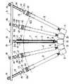
図1は本発明の体外で脊椎を矯正する脊椎矯正装置の使用状態を示す図である。この体外で脊椎を矯正する装置1は、5本の椎体固定具取付け装置2,2…と、各椎体固定具取付け装置2を互いに連結して各椎体固定具取付け装置2に矯正作用を加える矯正用プレート3とから構成されている。矯正用プレート3は、複数の椎体固定具取付け装置2の配列方向を矯正して脊椎の前後方向を矯正する作用をする。本発明の好ましい実施の形態では、側弯症患者の処置すべき椎体31を5つとし、これに対応して椎体固定具取付け装置を5本とした。
【0010】
各椎体固定具取付け装置2は、図3に示すように、先端に拡径部4を設けた外筒体5と、先端に椎体固定具保持部6を設け外筒体5が摺動自在に支持される内筒体7と、この内筒体7の椎体固定具保持部6に設けられた環状溝と、この環状溝に設けられた半径方向に移動可能な球状係止体8,8とを有する。球状係止体8は、環状溝に設けられた開口を通して一部が内側に突き出る。内筒体7に設けた椎体固定具保持部6に図4に示す椎体固定具9が装着される。椎体固定具9の外面形状に対応して内筒体7の椎体固定具保持部6の内面形状が決められる。
【0011】
上記外筒体5の基端部には、図3に示すように大径部10が形成されている。この大径部10にはコイルばね11が配置されている。コイルばね11は、一端を大径部10の座部に座し他端をカバー12を介して内筒体7に設けた止め輪13に当接し、外筒体5を先端方向に常時押圧している。
すなわち、外筒体5は、常時、拡径部4に続く内面で内筒体7の椎体固定具保持部6に設けた球状係止体8,8を半径方向内方に押圧し、球状係止体8の一部を椎体固定具保持部6の内面より内側に突出させ、椎体固定具保持部6の内面より内側に突出する球状係止体8が椎体固定具保持部6に装着された椎体固定具9を係合し、椎体固定具9を椎体固定具保持部6に固定している。椎体固定具9の椎体固定具保持部6への固定は、椎体固定具9の装着という一動作で行なうことができる。
【0012】
上記内筒体7の基端側は外筒体5の基端部に設けた大径部10より突出し、この突出部にねじ部14および6角ヘッド部15が形成されている。そして、ねじ部14にはナット16が螺合される。ねじ部14は、断面形状が両側部分を切り欠いた略長円形をなしている。図1に示すように、上記椎体固定具取付け装置2の内の両端に位置する椎体固定具取付け装置2の突出部には開口2aが形成されている。この開口2aには後述する圧縮矯正保持装置40が装着される。この圧縮矯正装置40は、複数の椎体固定具取付け装置2を脊椎の処置すべき各椎体31が接する方向に矯正して脊椎の左右方向の曲りを矯正する作用をする。
【0013】
上記各椎体固定具取付け装置2に上記矯正用プレート3が装着される。矯正用プレート3は、長手方向に延び、内面に内筒体7のねじ部14が摺接する細長い溝を有する。矯正用プレート3は、細長い溝の対向する内面に内筒体7のねじ部14の両側部分を切り欠いた小径部分が接することで各椎体固定具取付け装置2は配列方向が同一方向に整列され、これに伴って、各椎体固定具取付け装置2の椎体固定具保持部6に固定された椎体固定具9は開口部21(図4)が同一方向の向きに整列される。また、矯正用プレート3は、図2に示すように、下面に6角ヘッド部15の上端が当接することで、各椎体固定具取付け装置2の高さ位置を調節し、ねじ部14にナット16を螺合することで6角ヘッド部15とナット16により挟持される。矯正用プレート3を6角ヘッド部15とナット16により挟持すると、各椎体固定具取付け装置2に各椎体が接する方向の矯正力が作用する。
【0014】
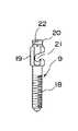
上記椎体固定具9は、図4に示すように、先端側から順にスクリュー部18とロッド取付け部19とヘッド部20とを有する。ロッド取付け部19は両側を略平面としこの側面に開口する孔21を有する。椎体固定具9は、両側を略平面としたことで、椎体固定具保持部6に位置決めされて保持される。ロッド取付け部19に設けた孔21に椎体固定具9同士を互いに連結するための図示しないロッドが装着される。ヘッド部20には環状溝22が形成され、この環状溝22に椎体固定具保持部6に設けた球状係止体8が係止される。
【0015】
複数本の椎体固定具取付け装置2は、図5に示す圧縮矯正装置40によって各椎体31が接する方向の矯正が作用しかつ各椎体31が接する位置に維持することができる。
上記圧縮矯正装置40は、図5に示すように、軸部41を有する固定保持具42と、この固定保持具42に固着されたラック43と、軸部44を有しラック43に摺動自在に配置された可動保持具45と、この可動保持具45をラック43に沿って動かすハンドル46と、可動保持具45を所定の位置に固定する固定手段とを有する。圧縮矯正装置40の固定保持具42の軸部41は、一端側に位置する椎体固定具取付け装置2の内筒体7の6角ヘッド部15より基端側に設けた開口2aに装着され、可動保持具45の軸部44は、他端側に位置する椎体固定具取付け装置2の内筒体7の6角ヘッド部15より基端側にに設けた開口2aに装着される。
【0016】
すなわち、上記圧縮矯正装置40は、一端側に位置する椎体固定具取付け装置2の内筒体7の開口2aに固定保持具42の軸部41を挿入し、可動保持具45をラック43に沿って移動させ、可動保持具45の軸部44を他端側に位置するシャフト2の椎体固定具取付け装置2の内筒体7の開口2aに挿入することで椎体固定具取付け装置2,2に取付けられる。
なお、図1および図2において符号50は体側方内外境界面を示す。
【0017】
椎体固定具取付け装置2の作用を説明する。
椎体固定具9は、椎体固定具取付け装置2の先端に設けた椎体固定具保持部6にヘッド部20を先にして挿入される。椎体固定具9のヘッド部20に続くロッド取付け部19は両側を略平面とした断面形状を略長円形とし、椎体固定具保持部6の内面形状もこの形状に対応しているので、椎体固定具9は、椎体固定具保持部6に方向を定めた状態で挿入される。椎体固定具9が椎体固定具保持部6に完全に挿入されると、ヘッド部20の環状溝22に外筒体5の拡径部4に続く内面で内方に押圧される球状係止部8が嵌入し、椎体固定具9が椎体固定具保持部6に固定保持される。この固定保持は一動作で行なわれる。
【0018】
椎体固定具9を固定保持した椎体固定具取付け装置2は、側弯症患者に設けた開口を通して挿入し、椎体固定具9を内視鏡により映し出される映像により対応する椎体31の所定位置に位置させる。
ついで、椎体固定具取付け装置2を椎体固定具9のスクリュー部18が椎体31に螺入する方向に回すと、椎体固定具9は椎体固定具保持部6に回らないように保持されているので、椎体固定具9は対応する椎体31に螺結される。
【0019】
椎体固定具9が椎体31に螺結されたら、椎体固定具取付け装置2の外筒体5の大径部10を持って、外筒体5を基端方向にコイルばね11の力に抗して摺動すると、外筒体5の拡径部4が球状係止部8に対応した位置に移動し、球状係止部8が半径方向外方に移動し、球状係止部8がヘッド部20に設けた環状溝22から外れる。この動作は一動作で行なわれる。
椎体固定具取付け装置2は、球状係止部8が環状溝22から外れると椎体固定具9と椎体固定具保持部6は係合状態から脱するので、椎体固定具取付け装置2は、椎体固定具9を椎体31に固定したまま体外に取り出される。この動作は人体外で一動作で行なうことができる。
【0020】
5本の椎体固定具取付け装置2を用いた脊椎矯正装置の作用を説明する。
5本の椎体固定具取付け装置2として、図1に示すように、2本の長い椎体固定具取付け装置2と、2本の中間の椎体固定具取付け装置2と、1本の短い椎体固定具取付け装置2が準備される。
まず、5本の椎体固定具取付け装置2の椎体固定具保持部6にそれぞれ椎体固定具9を固定保持させる。この操作は前述した方法で行なわれる。
つぎに、短い椎体固定具取付け装置2を側弯症患者に設けた開口を通して挿入し、短い椎体固定具取付け装置2に設けた椎体固定具9を内視鏡により映し出される映像により対応する椎体31の所定位置に位置させ、短い椎体固定具取付け装置2をスクリュー部18が椎体31に螺入する方向に回して、椎体固定具9をを対応する椎体31に螺結する。
【0021】
つぎに、2本の中間の椎体固定具取付け装置2を側弯症患者に設けた開口を通して挿入し、中間の椎体固定具取付け装置2に設けた椎体固定具9を内視鏡により映し出される映像により対応する椎体31の所定位置に位置させ、中間の椎体固定具取付け装置2をスクリュー部18が椎体31に螺入する方向に回して、椎体固定具9を対応する椎体31に螺結する。
【0022】
つぎに、2本の長い椎体固定具取付け装置2を側弯症患者に設けた開口を通して挿入し、長い椎体固定具取付け装置2に設けた椎体固定具9を内視鏡により映し出される映像により対応する椎体31の所定位置に位置させ、長い椎体固定具取付け装置2をスクリュー部18が椎体31に螺入する方向に回して、椎体固定具9を対応する椎体31に螺結する。
これにより、5本の椎体固定具取付け装置2に装着された椎体固定具9は対応する椎体31に螺結される。
【0023】
つぎに、矯正用プレート3の細長い溝に5本の椎体固定具取付け装置2のねじ部14を挿通する。各椎体固定具取付け装置2は、ねじ部14の両側を切り欠いた小径部分が細長い溝の内面に摺接するので、配列方向が同一方向に整列される。各椎体固定具取付け装置2の同一方向の整列により、椎体固定具取付け装置2の椎体固定具保持部6に固定保持された椎体固定具9も開口部21が同一の向きに整列される。
【0024】
つぎに、各椎体固定具取付け装置2のねじ部14にナット16をかるく螺合し、中央に位置する短い椎体固定具取付け装置2のねじ部14に設けたナット16を締める方向に回して、矯正用プレート3を6角ヘッド部15とナット16で挟持する。
つぎに、中間に位置する椎体固定具取付け装置2,2、すなわち図1において左から2番目と4番目の椎体固定具取付け装置2,2に、一方の椎体固定具取付け装置2の内筒体7の開口2aに固定保持具42の軸部41を挿入し、他方の椎体固定具取付け装置2の内筒体7の開口2aに可動保持具45の軸部44を挿入することで圧縮矯正装置40を取り付ける。そして、2番目と4番目の椎体固定具取付け装置2,2を圧縮矯正装置40により矯正用プレート3の細長い溝に沿って中央の方向に図2に示す位置まで動かし、2番目と4番目の椎体固定具取付け装置2のねじ部14に設けたナット16を締める方向に回して、矯正用プレート3を6角ヘッド部15とナット16で挟持する。
つぎに、端側に位置する椎体固定具取付け装置2,2、すなわち図1において左から1番目と5番目の椎体固定具取付け装置2,2に、圧縮矯正装置40を同様に取り付ける。そして、1番目と5番目の椎体固定具取付け装置2,2を圧縮矯正装置40により矯正用プレート3の細長い溝に沿って中央の方向に図2に示す位置まで動かし、1番目と5番目の椎体固定具取付け装置2のねじ部14に設けたナット16を締める方向に回して、矯正用プレート3を6角ヘッド部15とナット16で挟持する。
この一連の操作により、椎体固定具取付け装置2に各椎体が接する方向の矯正力が作用し、この矯正力は、椎体固定具取付け装置2および椎体固定具9を介して側弯症患者の椎体31に作用し、椎体31の位置が矯正される。この椎体31の位置矯正は、内視鏡により映し出される映像により確認される。
【0025】
椎体31の位置矯正が確認されたら、中間に位置する3本の椎体固定具取付け装置2を前述した方法により椎体固定具9から離脱し、各椎体固定具取付け装置2を側弯症患者から抜き取る。
ついで、図示しないロッドを、図示しない器具を用いて側弯症患者に設けた開口を通して挿入し、内視鏡により映し出される映像により、ロッドを椎体31に螺結された椎体固定具9のロッド取付け部19に設けた開口を通して孔に装着し、ロッドを椎体固定具9に固定する。
【0026】
つぎに、両端に位置する椎体固定具取付け装置2を前述した方法により椎体固定具9から離脱し、側弯症患者から抜き取る。
ついで、図示しないロッドを、図示しない器具を用いて側弯症患者に設けた開口を通して挿入し、内視鏡により映し出される映像により、ロッドを椎体31に螺結された椎体固定具9のロッド取付け部19に設けた開口を通して孔に装着し、ロッドを椎体固定具9に固定する。
これにより、側弯症患者の脊椎矯正が終了する。
【0027】
両端に位置する2本の椎体固定具取付け装置2に、図5に示す圧縮矯正装置40取り付けることで、側弯症患者の脊椎の椎体の位置を矯正することができる。 すなわち、圧縮矯正装置40の固定保持具42の軸部41を、一端側に位置する椎体固定具取付け装置2に設けた開口2aに挿入し、可動保持具45をラック43に沿って移動させて、可動保持具45の軸部44を他端側に位置する椎体固定具取付け装置2に設けた開口2aに挿入し、可動保持具45をラック43に固定し、この圧縮矯正装置40により矯正作用を行ないその矯正位置を維持する。
なお、上記実施の形態では、5本の椎体固定具取付け装置2を用いて説明したが、この椎体固定具取付け装置2の数は、処理すべき椎体31の数に対応して変動するものである。
【0028】
以上述べたように本発明によれば、側弯症患者に椎体固定具取付け装置の通る開口を設けるだけで、椎体固定具を人体の外部から椎体に固定でき、椎体固定具取付け装置に矯正手段を取り付け、矯正手段の矯正力を椎体固定具取付け装置を介して椎体固定具に伝えることで、側弯症患者の脊椎矯正を行なうことができる。
【図面の簡単な説明】
【図1】 本発明による椎体固定具を体外で脊椎に固定する椎体固定具取付け装置を用いた脊椎矯正装置を示す図。
【図2】 図1の脊椎矯正装置の使用状態を示す図。
【図3】 椎体固定具取付け装置の断面図。
【図4】 椎体固定具の側面図。
【図5】 矯正保持装置を示す図。
【図6】 側弯症患者の腹部を切開した状態を示す図。
【符号の説明】
2 椎体固定具取付け装置
3 矯正用プレート
4 拡径部
5 外筒体
6 椎体固定具保持部
7 内筒体アウトリガーシャフト
8 球状係止部
9 椎体固定具
18 スクリュー部
19 ロッド取付け部
20 ヘッド部
22 環状溝
31 椎体
40 圧縮矯正装置[0001]
BACKGROUND OF THE INVENTION
The present invention relatesto a spinal correction devicehaving a vertebral body fixing device for fixing , for example,a vertebral body fixing device for correcting torsion and bending of a vertebral body of a scoliosis patient to the vertebral body of the spine from the outside of a human body .
[0002]
[Prior art]
For example, the spine of a scoliosis patient protrudes as a three-dimensional twist and bends in an arc, and in order to correct the twist and curvature of the vertebral body of such a scoliosis patient, It is necessary to correct both the left and right side bends.
[0003]
Surgical treatment methods to correct vertebral body torsion and bending of scoliosis patients include an anterior treatment method in which the vertebral body is corrected from the lateral side (referred to as anterior in medicine) and a posterior direction in which the vertebral body is corrected from the rear side. There is a treatment system.
[0004]
As an anterior correction device, a plurality of vertebral body plates, a vertebral body screw that is screwed into the vertebral body through the opening of each vertebral body plate, a rod that connects the vertebral body screws threaded into the vertebral body, and a vertebral body The one constituted by a set screw provided on the top surface of the screw head is already known.
[0005]
To attach the anterior correction device to the vertebral body, as shown in FIG. 6, the chest or abdomen of the scoliosis patient is opened widely using a scalpel or the like to expose the
[0006]
[Problems to be solved by the invention]
Since the anterior correction device cannot be attached to a scoliosis patient unless the chest or abdomen of the scoliosis patient is opened widely with a scalpel or the like, the burden on the scoliosis patient is great at the time of attachment. In addition to requiring treatment such as suturing, a considerable period is required for postoperative recovery of patients with scoliosis.
[0007]
The present invention has been made in consideration of the above problems, outside the body usinga vertebral body fixing tool mountingequipment to the vertebral body fastener can be secured to vertebral bodies of the spine outside the body to vertebral body of a patient scoliosis spine An object of the present invention is to provide a spinal correction device that can correct the position of the vertebral body of the spine.
[0008]
[Means for Solving the Problems]
The spinal correction device for correcting the spine outside the body according to the present invention is aplurality of vertebral body fixing device attachment devices, each vertebral body fixing device attachment device including an inner cylinder body having a vertebral body fixation device holding part at a distal end. The vertebral body fixing device holding portion of the inner cylindrical body is provided with a vertebral body fixing device locking means provided so as to be movable in the radial direction, and a distal end has a large-diameter portion surrounding the vertebral body fixing device holding portion of the inner cylindrical body. A vertebral body fixing device having an outer cylinder slidably mounted on the inner cylindrical body, and a repression means for repressing the outer cylinder in the distal direction, and a base end of each vertebral body fixing device And a means for aligning the directions held by the vertebral body fixing device holding means on the vertebral body fixing device holding part of the inner cylindrical body of each vertebral body fixing device mounting apparatus. A vertebral body fixing device, and a correction means attached to a correction means receiving part of each vertebral body fixing device, and the vertebral body fixing device locking means. An annular groove provided in the vertebral body fixing tool holding part of the inner cylinder, a spherical locking part in which a part of the annular groove is protruded inwardly, an inner surface of the large diameter part of the outer cylinder, and this And a straightening first means for correcting the anteroposterior direction of the spine by correcting the arrangement direction of the vertebral body fixing device, and the correction means. And a second correcting means for correcting the bending of the spine in the left-right direction by correcting the vertebral body fixing device in a direction in which the vertebral bodies of the spine come into contact with each other. The position of the vertebral body of the spine can be corrected through the vertebral body fixing device by applying a correction force to the vertebral body fixing device that is fixed to the body and holding the vertebral body fixing device.
[0009]
DETAILED DESCRIPTION OF THE INVENTION
Embodiments of the present invention will be described below with reference to the drawings.
FIG. 1 is a view showing a use state of a spinal correction device for correcting a spine outside the body of the present invention. The device 1 for correcting the spine outside the body is connected to the five vertebral body fixing
[0010]
As shown in FIG. 3, each vertebral body fixing
[0011]
A large-
That is, the outer cylindrical body 5 always presses the spherical locking bodies 8, 8 provided on the vertebral body fixing
[0012]
The proximal end side of the inner cylindrical body 7 protrudes from a
[0013]
The
[0014]
As shown in FIG. 4, the vertebral
[0015]
The plurality of vertebral body fixing
As shown in FIG. 5, the
[0016]
That is, in the
In FIGS. 1 and 2,
[0017]
The operation of the vertebral body fixing
The vertebral
[0018]
The vertebral body fixing
Next, when the vertebral body fixing
[0019]
When the vertebral
In the vertebral body fixing
[0020]
The operation of the spinal correction device using the five vertebral body fixing
As shown in FIG. 1, the five vertebral
First, the vertebral
Next, the short vertebral
[0021]
Next, the two intermediate vertebral
[0022]
Next, two long vertebral body fixing
As a result, the vertebral
[0023]
Next, the
[0024]
Next, the
Next, the vertebral body fixing
Next, the
By this series of operations, a correction force in the direction in which each vertebral body comes into contact with the vertebral body fixing
[0025]
When the position correction of the
Next, a rod (not shown) is inserted through an opening provided in a scoliosis patient using a tool (not shown), and the rod of the vertebral
[0026]
Next, the vertebral body fixing
Next, a rod (not shown) is inserted through an opening provided in a scoliosis patient using a tool (not shown), and the rod of the vertebral
Thereby, the spinal correction of the scoliosis patient is completed.
[0027]
By attaching the
In the above embodiment, the five vertebral body fixing
[0028]
As described above, according to the present invention, the vertebral body fixing device can be fixed to the vertebral body from the outside of the human body simply by providing the scoliosis patient with an opening through which the vertebral body fixing device passes. By attaching the correction means to the vertebral body and transmitting the correction force of the correction means to the vertebral body fixing device via the vertebral body fixing device attachment apparatus, the spine correction of the scoliosis patient can be performed.
[Brief description of the drawings]
FIG. 1 is a view showing a spinal correction device using a vertebral body fixing device for fixing a vertebral body fixing device to a spine outside the body according to the present invention.
FIG. 2 is a diagram showing a use state of the spinal correction device of FIG. 1;
FIG. 3 is a cross-sectional view of the vertebral body fixing device.
FIG. 4 is a side view of a vertebral body fixing device.
FIG. 5 is a view showing a correction holding device.
FIG. 6 is a view showing a state in which the abdomen of a scoliosis patient is incised.
[Explanation of symbols]
2 vertebral
Claims (2)
Translated fromJapanesePriority Applications (1)
| Application Number | Priority Date | Filing Date | Title |
|---|---|---|---|
| JP05620497AJP3929538B2 (en) | 1997-03-11 | 1997-03-11 | Spine correction device having a vertebral body fixing device |
Applications Claiming Priority (1)
| Application Number | Priority Date | Filing Date | Title |
|---|---|---|---|
| JP05620497AJP3929538B2 (en) | 1997-03-11 | 1997-03-11 | Spine correction device having a vertebral body fixing device |
Publications (2)
| Publication Number | Publication Date |
|---|---|
| JPH10248855A JPH10248855A (en) | 1998-09-22 |
| JP3929538B2true JP3929538B2 (en) | 2007-06-13 |
Family
ID=13020597
Family Applications (1)
| Application Number | Title | Priority Date | Filing Date |
|---|---|---|---|
| JP05620497AExpired - LifetimeJP3929538B2 (en) | 1997-03-11 | 1997-03-11 | Spine correction device having a vertebral body fixing device |
Country Status (1)
| Country | Link |
|---|---|
| JP (1) | JP3929538B2 (en) |
Cited By (1)
| Publication number | Priority date | Publication date | Assignee | Title |
|---|---|---|---|---|
| KR20140037135A (en)* | 2011-06-23 | 2014-03-26 | 스파인웨이 | Surgical device for correcting deformations in the spinal column |
Families Citing this family (9)
| Publication number | Priority date | Publication date | Assignee | Title |
|---|---|---|---|---|
| US6530929B1 (en)* | 1999-10-20 | 2003-03-11 | Sdgi Holdings, Inc. | Instruments for stabilization of bony structures |
| US9539012B2 (en) | 2002-10-30 | 2017-01-10 | Zimmer Spine, Inc. | Spinal stabilization systems with quick-connect sleeve assemblies for use in surgical procedures |
| AU2003287273C1 (en) | 2002-10-30 | 2010-01-07 | Zimmer Spine, Inc. | Spinal stabilization system insertion and methods |
| ES2318917B1 (en)* | 2005-03-30 | 2010-02-04 | Sdgi Holdings Inc. | SYSTEM FOR THE THREE-DIMENSIONAL CORRECTION OF THE CURVATURE OF THE VERTEBRAL COLUMN IN PROBLEMS OF SCHOLIOSIS BY COPLANAR ALIGNMENT OF THE PEDICULAR SCREWS. |
| US8177817B2 (en)* | 2005-05-18 | 2012-05-15 | Stryker Spine | System and method for orthopedic implant configuration |
| US9907582B1 (en) | 2011-04-25 | 2018-03-06 | Nuvasive, Inc. | Minimally invasive spinal fixation system and related methods |
| US8936605B2 (en)* | 2011-12-30 | 2015-01-20 | Blackstone Medical, Inc. | Direct vertebral rotation tool and method of using same |
| US10098665B2 (en) | 2012-08-01 | 2018-10-16 | DePuy Synthes Products, Inc. | Spine derotation system |
| US9763702B2 (en) | 2012-11-16 | 2017-09-19 | DePuy Synthes Products, Inc. | Bone fixation assembly |
- 1997
- 1997-03-11JPJP05620497Apatent/JP3929538B2/ennot_activeExpired - Lifetime
Cited By (1)
| Publication number | Priority date | Publication date | Assignee | Title |
|---|---|---|---|---|
| KR20140037135A (en)* | 2011-06-23 | 2014-03-26 | 스파인웨이 | Surgical device for correcting deformations in the spinal column |
Also Published As
| Publication number | Publication date |
|---|---|
| JPH10248855A (en) | 1998-09-22 |
Similar Documents
| Publication | Publication Date | Title |
|---|---|---|
| US10292736B2 (en) | Rod reduction device and method of use | |
| US7799036B2 (en) | Method and apparatus for securing vertebrae | |
| US7942909B2 (en) | Thread-thru polyaxial pedicle screw system | |
| US20050085813A1 (en) | System and method for stabilizing of internal structures | |
| JP4965856B2 (en) | Variable offset connector and bone fixation method | |
| US9101353B2 (en) | Method of securing vertebrae | |
| JP3022404B2 (en) | A device that holds the vertebrae of the spine in a desired spatial relationship | |
| US5219349A (en) | Spinal fixator reduction frame | |
| JP4131612B2 (en) | Vertebral joint device | |
| US20080009863A1 (en) | Pedicle screw distractor and associated method of use | |
| US20060293678A1 (en) | Method and apparatus for securing vertebrae | |
| US20050192569A1 (en) | Apparatus for spinal stabilization | |
| JP2019523076A (en) | Restrained implants and systems for orthopedics | |
| JP5654614B2 (en) | Implant placement device | |
| WO2012006554A2 (en) | Locking polyaxial ball and socket fastener | |
| JP3929538B2 (en) | Spine correction device having a vertebral body fixing device | |
| US20120221059A1 (en) | Cervical spine clamp | |
| JP2019150562A (en) | Compressor/distractor | |
| EP2470095B1 (en) | Surgical clamping device | |
| CN116250944B (en) | Patient tracer fixing fixture | |
| US5203783A (en) | Osteosynthetic fixation and force transmitting apparatus | |
| CN108143450A (en) | One kind struts pressue device and its application method | |
| KR101709585B1 (en) | Orthopedic surgical clamping apparatus | |
| AU2024219848A1 (en) | Bone clamp | |
| US12048461B2 (en) | Medical transverse connector having a floating bearing |
Legal Events
| Date | Code | Title | Description |
|---|---|---|---|
| A621 | Written request for application examination | Free format text:JAPANESE INTERMEDIATE CODE: A621 Effective date:20040303 | |
| A977 | Report on retrieval | Free format text:JAPANESE INTERMEDIATE CODE: A971007 Effective date:20060403 | |
| A131 | Notification of reasons for refusal | Free format text:JAPANESE INTERMEDIATE CODE: A131 Effective date:20060602 | |
| A521 | Written amendment | Free format text:JAPANESE INTERMEDIATE CODE: A523 Effective date:20060731 | |
| A131 | Notification of reasons for refusal | Free format text:JAPANESE INTERMEDIATE CODE: A131 Effective date:20061024 | |
| A521 | Written amendment | Free format text:JAPANESE INTERMEDIATE CODE: A523 Effective date:20061221 | |
| TRDD | Decision of grant or rejection written | ||
| A01 | Written decision to grant a patent or to grant a registration (utility model) | Free format text:JAPANESE INTERMEDIATE CODE: A01 Effective date:20070209 | |
| A61 | First payment of annual fees (during grant procedure) | Free format text:JAPANESE INTERMEDIATE CODE: A61 Effective date:20070307 | |
| R150 | Certificate of patent or registration of utility model | Free format text:JAPANESE INTERMEDIATE CODE: R150 | |
| FPAY | Renewal fee payment (event date is renewal date of database) | Free format text:PAYMENT UNTIL: 20100316 Year of fee payment:3 | |
| FPAY | Renewal fee payment (event date is renewal date of database) | Free format text:PAYMENT UNTIL: 20110316 Year of fee payment:4 | |
| FPAY | Renewal fee payment (event date is renewal date of database) | Free format text:PAYMENT UNTIL: 20120316 Year of fee payment:5 | |
| FPAY | Renewal fee payment (event date is renewal date of database) | Free format text:PAYMENT UNTIL: 20120316 Year of fee payment:5 | |
| FPAY | Renewal fee payment (event date is renewal date of database) | Free format text:PAYMENT UNTIL: 20130316 Year of fee payment:6 | |
| FPAY | Renewal fee payment (event date is renewal date of database) | Free format text:PAYMENT UNTIL: 20130316 Year of fee payment:6 | |
| FPAY | Renewal fee payment (event date is renewal date of database) | Free format text:PAYMENT UNTIL: 20140316 Year of fee payment:7 | |
| R250 | Receipt of annual fees | Free format text:JAPANESE INTERMEDIATE CODE: R250 | |
| R250 | Receipt of annual fees | Free format text:JAPANESE INTERMEDIATE CODE: R250 | |
| R250 | Receipt of annual fees | Free format text:JAPANESE INTERMEDIATE CODE: R250 | |
| EXPY | Cancellation because of completion of term |