JP3929501B2 - Method and apparatus for embedding additional data in encoded signal - Google Patents
Method and apparatus for embedding additional data in encoded signalDownload PDFInfo
- Publication number
- JP3929501B2 JP3929501B2JP52918098AJP52918098AJP3929501B2JP 3929501 B2JP3929501 B2JP 3929501B2JP 52918098 AJP52918098 AJP 52918098AJP 52918098 AJP52918098 AJP 52918098AJP 3929501 B2JP3929501 B2JP 3929501B2
- Authority
- JP
- Japan
- Prior art keywords
- signal
- additional data
- encoded signal
- encoded
- encoder
- Prior art date
- Legal status (The legal status is an assumption and is not a legal conclusion. Google has not performed a legal analysis and makes no representation as to the accuracy of the status listed.)
- Expired - Lifetime
Links
Images


Classifications
- G—PHYSICS
- G06—COMPUTING OR CALCULATING; COUNTING
- G06T—IMAGE DATA PROCESSING OR GENERATION, IN GENERAL
- G06T1/00—General purpose image data processing
- G06T1/0021—Image watermarking
- G06T1/0028—Adaptive watermarking, e.g. Human Visual System [HVS]-based watermarking
- G06T1/0035—Output size adaptive watermarking
- H—ELECTRICITY
- H04—ELECTRIC COMMUNICATION TECHNIQUE
- H04N—PICTORIAL COMMUNICATION, e.g. TELEVISION
- H04N19/00—Methods or arrangements for coding, decoding, compressing or decompressing digital video signals
- H04N19/46—Embedding additional information in the video signal during the compression process
- H04N19/467—Embedding additional information in the video signal during the compression process characterised by the embedded information being invisible, e.g. watermarking
- G—PHYSICS
- G11—INFORMATION STORAGE
- G11B—INFORMATION STORAGE BASED ON RELATIVE MOVEMENT BETWEEN RECORD CARRIER AND TRANSDUCER
- G11B20/00—Signal processing not specific to the method of recording or reproducing; Circuits therefor
- G11B20/00086—Circuits for prevention of unauthorised reproduction or copying, e.g. piracy
- G11B20/00884—Circuits for prevention of unauthorised reproduction or copying, e.g. piracy involving a watermark, i.e. a barely perceptible transformation of the original data which can nevertheless be recognised by an algorithm
- G11B20/00891—Circuits for prevention of unauthorised reproduction or copying, e.g. piracy involving a watermark, i.e. a barely perceptible transformation of the original data which can nevertheless be recognised by an algorithm embedded in audio data
- H—ELECTRICITY
- H04—ELECTRIC COMMUNICATION TECHNIQUE
- H04N—PICTORIAL COMMUNICATION, e.g. TELEVISION
- H04N19/00—Methods or arrangements for coding, decoding, compressing or decompressing digital video signals
- H—ELECTRICITY
- H04—ELECTRIC COMMUNICATION TECHNIQUE
- H04N—PICTORIAL COMMUNICATION, e.g. TELEVISION
- H04N21/00—Selective content distribution, e.g. interactive television or video on demand [VOD]
- H04N21/20—Servers specifically adapted for the distribution of content, e.g. VOD servers; Operations thereof
- H04N21/23—Processing of content or additional data; Elementary server operations; Server middleware
- H04N21/238—Interfacing the downstream path of the transmission network, e.g. adapting the transmission rate of a video stream to network bandwidth; Processing of multiplex streams
- H04N21/2389—Multiplex stream processing, e.g. multiplex stream encrypting
- H04N21/23892—Multiplex stream processing, e.g. multiplex stream encrypting involving embedding information at multiplex stream level, e.g. embedding a watermark at packet level
- H—ELECTRICITY
- H04—ELECTRIC COMMUNICATION TECHNIQUE
- H04N—PICTORIAL COMMUNICATION, e.g. TELEVISION
- H04N21/00—Selective content distribution, e.g. interactive television or video on demand [VOD]
- H04N21/80—Generation or processing of content or additional data by content creator independently of the distribution process; Content per se
- H04N21/83—Generation or processing of protective or descriptive data associated with content; Content structuring
- H04N21/835—Generation of protective data, e.g. certificates
- H04N21/8358—Generation of protective data, e.g. certificates involving watermark
- G—PHYSICS
- G11—INFORMATION STORAGE
- G11B—INFORMATION STORAGE BASED ON RELATIVE MOVEMENT BETWEEN RECORD CARRIER AND TRANSDUCER
- G11B20/00—Signal processing not specific to the method of recording or reproducing; Circuits therefor
- G11B20/00007—Time or data compression or expansion
- G11B2020/00014—Time or data compression or expansion the compressed signal being an audio signal
- G11B2020/00065—Sigma-delta audio encoding
Landscapes
- Engineering & Computer Science (AREA)
- Signal Processing (AREA)
- Multimedia (AREA)
- Computer Security & Cryptography (AREA)
- Theoretical Computer Science (AREA)
- Physics & Mathematics (AREA)
- General Physics & Mathematics (AREA)
- Editing Of Facsimile Originals (AREA)
- Image Processing (AREA)
- Compression, Expansion, Code Conversion, And Decoders (AREA)
- Television Systems (AREA)
- Dc Digital Transmission (AREA)
- Signal Processing For Digital Recording And Reproducing (AREA)
Abstract
Description
Translated fromJapanese発明の技術分野
本発明は符号化された信号に付加データを埋込む方法および装置に関するものである。この方法は符号化信号をフィードバックして符号化を制御するステップを含む所定の符号化処理に従って信号を符号化するステップと、符号化された信号を修正して前記付加データを表わすステップとを具える。また、本発明はかかる符号化信号から付加データを抽出する方法および装置に関するものである。
発明の背景
オーディオおよびビデオ信号に電子透かしを埋込む必要性が増してきはじめた。この電子透かしとは、マルチメディア資産に、好適には不可視態様で埋込まれた付加データメッセージである。これら電子透かしは、例えば文書および視聴覚プログラムの出典または著作権の状態に関する情報である。これら電子透かしを用いて著作権者の法律的な防御を行い、著作権侵害の探索を行い、知的財産の保護を行うことができる。
上述したようにビデオ信号に電子透かしを付与する既知の方法はF.HartungおよびB.Giros著“生および圧縮ビデオのディジタル電子透かし”SPIE Vol. 2952,pp.205-212に記載されている。この著書では電子透かしは予測符号化(PまたはB)画像のDCT係数を含むMPEG2エンコーダの出力ビット流の選択されたDCT係数を修正することによって達成する。予測エンコーダは符号化処理を制御するフィードバックループを具える。入力信号自体ではなく予測エラー(入力信号と予測信号の差)を符号化する。予測信号は符号化信号を局部的に複号することによって得ることができる。
従来の方法では、電子透かしは慣例の符号化の後に挿入する。斯様にして符号化された信号に電子透かし処理を施し得る可能性は制限される。
発明の概要
本発明の目的は、知覚品質に悪影響を殆ど与えることなく符号化信号の多くのビットを変更し得る、符号化されたオーディオまたはビデオ信号に付加データを埋込む方法を提供せんとするにある。
この目的のため、本発明方法は、符号化された信号をフィードバックして符号化を制御するステップを含む所定の符号化処理に従って信号を符号化するステップと、符号化された信号を修正して付加データを表わすステップとを具える符号化された信号に付加データを埋込むに当たり、前記符号化された信号をフィードバックするステップを、前記符号化された信号を修正するステップの後に実行することを特徴とする。符号化された信号を修正するステップはエンコーダのフィードバックループ内で行う。従って、電子透かしを付与するための符号化された信号の修正がフィードバックされ、次の符号化処理で補償される。こうして埋込まれた電子透かしは、受信機において送信機における符号化処理で受けたのと同様に復号化処理を受ける。送信機における補償処理の結果として、受信機は入力信号の充分に良好なレプリカを再生する。信号対雑音比は著しく改善されるか、或は又、多くの電子透かしデータを所定の信号対雑音比で埋込むこができる。
本発明は、特に、単ビット符号化信号に付加データを埋込むために特に好適である。単ビット符号化信号は電子透かし処理の影響を特に受けやすい。エンコーダは各符号化ステップごとに1ビット出力サンプルを発生する。一般に、電子透かしを付与するための符号化信号の出力サンプルの修正は例えばマルチビットサンプルの値を単に変化させる場合よりも一層厳しい。
単ビット符号化の例はデルタ変調器、シグマ−デルタ変調器、およびノイズシェープエンコーダである。また、これらはフィードバックループを有するエンコーダのファミリーに属する。シグマ−デルタ変調は、2822400Hz(64*44100)のサンプリング周波数を用い、115dBの信号対雑音比を有するディジタルバーサタイルディスク(DVD)のオーディオバージョンに高品質オーディオを記録することを想定している。電子透かしは例えば出力ビット流の選択されたビットをディジタル電子透かしパターンのビットで置換えることによって挿入される。この挿入を従来既知のように、即ち、慣例の符号化後に行う場合には、電子透かしビットの挿入は大きな量子化雑音を発生する。例えば、1電子透かしビットによるシグマ−デルタ変調されたオーディオ信号の100ビットごとの1ビット置換によって−60dBまでの量子化雑音が発生する。これに対し、本発明によれば量子化雑音を1dB増大するだけで、シグマ−デルタ変調されたオーディオ信号を100ビット当たり1ビット変化させることができる。これはほぼ28000ビット/秒の電子透かしビットレートに相当する。
発明を実施するための最良の形態
図1は本発明による符号化オーディオまたはビデオ信号に付加データを埋込む装置のブロック回路図を示す。本例装置は予測エンコーダ1および修正回路2を具える。予測エンコーダ1は(アナログまたはディジタル)入力信号xを受けるとともに入力信号xから予測信号
修正回路2は符号化予測エラー信号yを受けるとともに所定の電子透かしwに従ってこの信号を修正するように配列する。この修正回路の例は既知である。前述したHartung等の文献では電子透かし信号wの8*8ブロックにDCTを施し、斯くして得たDCT係数を変換符号化予測エラー信号の選択されたDCT係数に加算する。他の例は、I.J.Cox, J.Kilian, T.LeightonおよびT.Shamoon著“ASecure Imperceptible yet Perceptually Salient, Spread Spectrum Watermark for Multimedia”Conference Record of Southcon 96,6月25−27日,1996年第192-197頁に記載されている。この文献では、一連の実数をDC係数を除く最高次数の変換係数に加算することによりビデオ信号に電子透かし処理を施すようにしている。
本発明によれば、この修正回路2を符号化段12および復号化段13間に、即ち、予測エンコーダのループ内に配置する。これがため、予測信号
図1に示すようなエンコーダから符号化された信号を復号化する受信機は一般にエンコーダの予測ループと同一であり、従って個別には示さない。
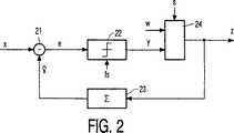
一層詳細な例を図2につき説明する。図2はアナログまたはPCM符号化オーディオ信号を符号化するデルタ変調器を示す。この回路配置は入力信号xから予測信号
本例では、修正回路はマルチプレクサとし、これによって、極性検出器の出力の選択されたビット(例えば、100番目のビット毎)を、選択信号sに応答して電子透かしビットパターンwに置換する。電子透かしを埋込む他の例では符号化信号の選択されたサンプルを反転し、電子透かしデータを順次の反転されたサンプル間のビット周期の数で表わすようにする必要がある。
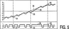
図3−5は図2に示す装置の作動を説明する種々の信号波形を示す。これらの図では記号30は入力信号xを示す。
例えば、図3は電子透かし機能のない従来のデルタ変調器の波形を示す。この図3では記号31は予測信号
図4は従来の技術により既知のように符号化信号を電子透かし処理する影響を説明する。記号34は、ビット流32の6番目、16番目および26番目のビット(図3)をディジタル電子透かしパターンw=“001”にそれぞれ相当する−1、−1および+1で置換して得られたビット流を示す。記号33はこのビット流を受信する受信機の出力信号を示す。この図から明らかなように信号対雑音比が著しく減少することを観察できる。
図5は本発明により電子透かしを埋込む効果を示す。記号35は予測信号
また、図5の記号35は受信機の出力信号を示す。波形33および35を比較することによって信号対雑音比が充分に改善されたことを示す。
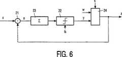
図6は本発明によるシグマ−デルタ変調器を示す。シグマ−デルタ変調はDVDのオーディオバージョンに高品質オーディオを記録するものである。このシグマ−デルタ変調は、デルタ変調器の予測ループのフィルタと同一のフィルタによって符号化前に、入力信号xをフィルタ処理する点でデルタ変調とは相違する。次いで、入力経路およびフィードバック経路のフィルタを符号化ループのフォワード経路の単一フィルタと置換する。従って、図6に示すシグマ−デルタ変調器は、フィルタ23がフィードバック経路からフォワード経路に移動した点で、図2に示すデルタ変調器とは相違する。
図7は電子透かし機能のない従来のシグマ−デルタ変調器の波形を示す。記号70は入力信号xを示し、記号71は符号化された出力信号を示す。シグマ−デルタ変調器によって、入力信号が大きくなるにつれてより多くの正のサンプルを発生する。記号70は入力信号xを示し、記号71は符号化された出力信号を示す。シグマ−デルタ変調器によって、入力信号が大きくなるにつれてより多くの正のサンプルを発生する。図7に示すように、−0.5Vの入力信号は3つの−1Vパルスと1つの+1Vパルスのシーケンスとして符号化され、0Vの入力信号は−1Vパルスおよび+1Vパルスの交互のシーケンスとして符号化され、+0.5Vの入力信号は3つの+1Vパルスと1つの−1Vパルスのシーケンスとして符号化される。この信号は、受信したパルスを再成形し低域通過フィルタを通過させることによって受信側で復号化される。図7では、ビット流の13サンプルを平均化することによって斯かる信号を復調する。記号72は、平均化処理によって生ずる遅延は別として、再構成された信号をも示す。斯くして再構成された信号は入力信号と時間的に整列される。
図8は従来技術に従って、即ち、慣例のシグマ−デルタ変調後に符号化信号を電子透かし処理する影響を示す。本例では、慣例のシグマ−デルタ変調器の−1サンプル73(図7)は、+1サンプル74と置換されている。この置換は符号化処理には影響を与えず、修正されていない符号化出力信号75の残部はそのままなる。記号76は受信側の再構成信号を示す。図7の再構成された信号72との差は記号77(図では信号の時間整列により時間的に早い時点)で著しくなり、復号化処理の残部中リップルを生ずるようになる。この場合にも信号対雑音比の大きな減少が観測される。
図9は本発明による同一の電子透かしサンプル74を埋込む処理の影響を示す。本発明によれば、この電子透かし処理の影響は入力側にフィードバックされ、電子透かしの挿入後に入力信号を個別に符号化することにより補償される。本例では再構成信号78は入力信号に著しく良好に類似している。2822400(64*44100)のサンプリング周波数fsで高品質オーディオ信号を符号化する図6に示すシグマ−デルタ変調器の特定の例は115dBの信号対雑音比を有する。この場合には、100サンプル当たり1サンプルの置換によって量子化雑音が1dB増大するだけであることが確かめられた。これは28000ビット/秒の電子透かしビットレートに相当する。
図10は図2に示すような装置によって発生するデルタ変調された信号から、または図6に示すような装置によって発生するシグマ−デルタ変調されたシグマ−デルタ変調器から埋込み電子透かしを抽出する装置を示す。修正された符号化信号zは選択信号sによってクロックされるレジスタ100のデルタ入力端子に供給する。レジスタ100の出力は電子透かしビットパターンwとなる。選択信号sによってビット流のどのビットが電子透かしビットであるかどうかを決める。この選択信号はサンプル周波数fsを所定数N,例えば、100で分周する分周段101によって発生させる。この信号は送信機における関連する選択信号sと同期するものとする。この同期化は電子透かし信号wに所定の同期化ビットパターンを組込むことによって達成する。かかる例では、同期検出器102によってこのパターンを検出し、同期パターンが検出されるまで駆動段101の位相を変化させるようにする。
図11は原入力信号xを受信側で使用可能である場合に使用することができる埋込み電子透かしを抽出する装置を示す。本例装置は図1に示す関連送信機と同一のエンコーダ1を具える。しかし、フィードバックループは電子透かしの付された信号zを受信する。従って、再構成された予測信号
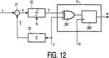
図12は(シグマ−)デルタ変調信号から電子透かしを抽出する特定の例を示す。図12において、記号21−23は図2に示す所と同一のデルタ変調器を構成する。抽出回路3は排他的ORゲート301を具え、これによって電子透かし信号zのビットまたは符号化信号yの関連するビットが等しいかどうかを決める。これらビットが等しくない場合には電子透かし信号zが反転ビットを桁上げするビット周期を検出する。検出された信号はカウンタ302に供給され、このカウンタはサンプル周波数fsでクロックされ、2つの連続する反転ビット間のビット周期の数が第1の所定数(例えば、75)である場合には2進数“0”を発生するとともにビット周期の数が第2の所定数(例えば、125)である場合には2進数“1”を発生する。
図13はこの例の動作を説明するための信号波形を示す。記号130は原入力信号xを示し、記号131は受信した電子透かし信号zを示し、記号132は電子透かし信号を復号化することにより得られる予測信号
要するに、フィードバックループを有するエンコーダ、例えば、シグマ−デルタ変調器(21、22、23)によって符号化された信号に電子透かしを埋込む方法を述べる。ディジタル電子透かしパターン(w)は、電子透かしパターンのサンプルにより符号化信号(y)の選択されたサンプルを修正(例えば、100番目のビット毎に置換)することによって信号(z)に埋込む。サンプルを修正する回路(24)はエンコーダのフィードバックループ内に位置させる。これがため、電子透かしの影響は次の符号化ステップで補償され、信号対雑音比はわずかに影響を受けるだけとなる。
【図面の簡単な説明】
図1は本発明による符号化オーディオまたはビデオ信号に付加データを埋込む装置を示すブロック回路図、
図2は本発明によるデルタ変調されたオーディオ信号に付加データを埋込む装置を示すブロック回路図、
図3−5は図2に示す本発明装置の作動を説明するための特性図、
図6は本発明によるシグマ−デルタ変調されたオーディオ信号に付加データを埋込む装置を示すブロック回路図、
図7−9は図6に示す本発明装置の作動を説明するための特性図、
図10は図2または図6に示す装置によって符号化された信号から埋込まれた電子透かしを抽出する装置を示すブロック回路図、
図11は図1に示す装置によって符号化された信号から埋込まれた電子透かしを抽出する装置を示すブロック回路図、
図12は(シグマ−)デルタ変調された信号電子透かしを抽出する他の例を示すブロック回路図、
図13は図6に示す例の作動を説明するための特性図である。TECHNICAL FIELD OF THE INVENTION The present invention relates to a method and apparatus for embedding additional data in an encoded signal. The method comprises the steps of encoding a signal according to a predetermined encoding process including the step of controlling the encoding by feeding back the encoded signal, and modifying the encoded signal to represent the additional data. Yeah. The present invention also relates to a method and apparatus for extracting additional data from such an encoded signal.
Background of the invention The need to embed digital watermarks in audio and video signals has begun to increase. This watermark is an additional data message embedded in a multimedia asset, preferably in an invisible manner. These digital watermarks are information about the source or copyright status of documents and audiovisual programs, for example. These digital watermarks can be used to protect the copyright holders legally, search for copyright infringement, and protect intellectual property.
As described above, a known method for adding a watermark to a video signal is described in "Digital watermarking of raw and compressed video" by F. Hartung and B. Giros, SPIE Vol. In this book, watermarking is achieved by modifying selected DCT coefficients of the output bitstream of the MPEG2 encoder, including the DCT coefficients of predictive encoded (P or B) images. The predictive encoder comprises a feedback loop that controls the encoding process. The prediction error (difference between the input signal and the prediction signal) is encoded instead of the input signal itself. The prediction signal can be obtained by locally decoding the encoded signal.
In the conventional method, the watermark is inserted after conventional encoding. The possibility that digital watermarking can be performed on a signal encoded in this way is limited.
SUMMARY OF THE INVENTION An object of the present invention is a method of embedding additional data in an encoded audio or video signal that can change many bits of the encoded signal with little adverse effect on perceived quality. There is to offer.
For this purpose, the method of the present invention includes a step of encoding a signal according to a predetermined encoding process including a step of controlling the encoding by feeding back the encoded signal, and modifying the encoded signal. Performing the step of feedback of the encoded signal after the step of modifying the encoded signal in embedding the additional data in the encoded signal comprising the step of representing the additional data. Features. The step of modifying the encoded signal is performed in the feedback loop of the encoder. Therefore, the modification of the encoded signal for adding the digital watermark is fed back and compensated for in the next encoding process. The digital watermark thus embedded is subjected to a decoding process at the receiver in the same manner as received by the encoding process at the transmitter. As a result of the compensation process at the transmitter, the receiver reproduces a sufficiently good replica of the input signal. The signal-to-noise ratio can be significantly improved, or a large amount of watermark data can be embedded with a predetermined signal-to-noise ratio.
The present invention is particularly suitable for embedding additional data in a single-bit encoded signal. Single-bit encoded signals are particularly susceptible to digital watermark processing. The encoder generates a 1-bit output sample for each encoding step. In general, correction of output samples of an encoded signal for adding a digital watermark is more severe than, for example, simply changing the value of a multi-bit sample.
Examples of single bit encoding are delta modulators, sigma-delta modulators, and noise shape encoders. They also belong to a family of encoders with feedback loops. Sigma-delta modulation assumes recording high quality audio on an audio version of a digital versatile disc (DVD) with a sampling frequency of 2822400 Hz (64 * 44100) and a signal to noise ratio of 115 dB. The watermark is inserted, for example, by replacing selected bits of the output bitstream with bits of the digital watermark pattern. When this insertion is performed as is known in the art, that is, after the conventional encoding, the insertion of a watermark bit generates a large quantization noise. For example, a 1-bit replacement for every 100 bits of a sigma-delta modulated audio signal with one watermark bit generates quantization noise up to -60 dB. On the other hand, according to the present invention, the sigma-delta modulated audio signal can be changed by 1 bit per 100 bits only by increasing the quantization noise by 1 dB. This corresponds to a watermark bit rate of approximately 28000 bits / second.
BEST MODE FORCARRYING OUT THE INVENTION FIG. 1 shows a block circuit diagram of an apparatus for embedding additional data in an encoded audio or video signal according to the present invention. The example apparatus comprises a
The
According to the invention, this
A receiver that decodes a signal encoded from an encoder as shown in FIG. 1 is generally identical to the prediction loop of the encoder and is therefore not shown separately.
A more detailed example will be described with reference to FIG. FIG. 2 shows a delta modulator that encodes an analog or PCM encoded audio signal. This circuit arrangement is based on the input signal x and the prediction signal.
In this example, the correction circuit is a multiplexer, whereby the selected bits (for example, every 100th bit) of the output of the polarity detector are replaced with the digital watermark bit pattern w in response to the selection signal s. Another example of embedding a watermark requires inverting selected samples of the encoded signal so that the watermark data is represented by the number of bit periods between successive inverted samples.
3-5 show various signal waveforms illustrating the operation of the apparatus shown in FIG. In these figures,
For example, FIG. 3 shows the waveform of a conventional delta modulator without a watermark function. In FIG. 3, symbol 31 is a prediction signal.
FIG. 4 illustrates the effect of watermarking an encoded signal as is known from the prior art. The
FIG. 5 illustrates the effect of embedding a digital watermark according to the present invention.
A
FIG. 6 shows a sigma-delta modulator according to the present invention. Sigma-delta modulation records high quality audio on an audio version of a DVD. This sigma-delta modulation differs from delta modulation in that the input signal x is filtered before being encoded by the same filter as that of the prediction loop of the delta modulator. The input path and feedback path filters are then replaced with a single filter in the forward path of the encoding loop. Therefore, the sigma-delta modulator shown in FIG. 6 is different from the delta modulator shown in FIG. 2 in that the
FIG. 7 shows a waveform of a conventional sigma-delta modulator without a digital watermark function.
FIG. 8 shows the effect of watermarking the encoded signal according to the prior art, ie after conventional sigma-delta modulation. In this example, the -1 sample 73 (FIG. 7) of the conventional sigma-delta modulator is replaced with the +1
FIG. 9 illustrates the effect of the process of embedding the
FIG. 10 shows an apparatus for extracting embedded watermarks from a delta modulated signal generated by an apparatus as shown in FIG. 2 or from a sigma-delta modulated sigma-delta modulator generated by an apparatus as shown in FIG. Indicates. The modified encoded signal z is supplied to the delta input terminal of the
FIG. 11 shows an apparatus for extracting an embedded watermark that can be used when the original input signal x is available on the receiving side. The example apparatus comprises the
FIG. 12 shows a specific example of extracting a watermark from a (sigma) delta modulated signal. In FIG. 12, symbols 21-23 constitute the same delta modulator as shown in FIG. The extraction circuit 3 comprises an exclusive OR
FIG. 13 shows signal waveforms for explaining the operation of this example.
In short, a method for embedding a digital watermark in a signal encoded by an encoder having a feedback loop, for example, a sigma-delta modulator (21, 22, 23) will be described. The digital watermark pattern (w) is embedded in the signal (z) by modifying (eg, replacing every 100th bit) a selected sample of the encoded signal (y) with a sample of the watermark pattern. A circuit (24) for modifying the sample is located in the feedback loop of the encoder. Thus, the effect of the watermark is compensated for in the next encoding step and the signal-to-noise ratio is only slightly affected.
[Brief description of the drawings]
FIG. 1 is a block circuit diagram showing an apparatus for embedding additional data in an encoded audio or video signal according to the present invention.
FIG. 2 is a block circuit diagram showing an apparatus for embedding additional data in a delta-modulated audio signal according to the present invention,
3-5 is a characteristic diagram for explaining the operation of the device of the present invention shown in FIG.
FIG. 6 is a block circuit diagram showing an apparatus for embedding additional data in a sigma-delta modulated audio signal according to the present invention.
FIG. 7-9 is a characteristic diagram for explaining the operation of the device of the present invention shown in FIG.
FIG. 10 is a block circuit diagram showing an apparatus for extracting an embedded watermark from a signal encoded by the apparatus shown in FIG. 2 or FIG.
FIG. 11 is a block circuit diagram showing an apparatus for extracting an embedded watermark from a signal encoded by the apparatus shown in FIG.
FIG. 12 is a block circuit diagram showing another example of extracting a (sigma) -delta modulated signal watermark;
FIG. 13 is a characteristic diagram for explaining the operation of the example shown in FIG.
Claims (8)
Translated fromJapanese符号化された信号を付加データに従って修正して前記符号化された信号に付加データを埋込むステップとを具える符号化信号に付加データを埋め込む方法において、
前記符号化された信号を修正するステップは、前記符号化された信号を前記エンコーダから前記帰還ループへ供給する前に実行し、
前記符号化された信号を修正するステップは、前記単ビット符号化信号の選択されたサンプルを反転し、埋込まれたデータが順次の反転サンプル間のサンプル周期の数により表わされることを特徴とする符号化信号に付加データを埋込む方法。An encoder and a feedback loop, and encoding the signal according to a predetermined predictive single bit encoding process;
In a method of embedding additional data in an encoded signal comprising the step of modifying the encoded signal according to additional data and embedding the additional data in the encoded signal,
The step of modifying the encoded signal is performed prior to supplying the encoded signal from the encoder to the feedback loop;
The step of modifying the encoded signal inverts selected samples of the single-bit encoded signal, and the embedded data is represented by the number of sample periods between successive inverted samples. A method of embedding additional data in an encoded signal .
エンコーダと帰還ループとを含み、前記受信符号化信号の原信号を該エンコーダに供給するとともに前記受信符号化信号を前記帰還ループに供給して前記原信号を前記所定の予測符号化処理に従って符号化するステップと、An encoder and a feedback loop, wherein the original signal of the received encoded signal is supplied to the encoder and the received encoded signal is supplied to the feedback loop to encode the original signal according to the predetermined predictive encoding process And steps to
符号化された原信号と前記受信符号化信号とを比較するステップとを具え、該符号化された原信号と前記受信符号化信号との差が前記付加データを表わすことを特徴とする受信符号化信号から付加データを抽出する方法。A received code comprising the step of comparing the encoded original signal and the received encoded signal, wherein a difference between the encoded original signal and the received encoded signal represents the additional data Method of extracting additional data from the digitized signal.
該エンコーダで符号化された信号を付加データに従って修正して前記符号化された信号に付加データを埋め込む手段と、
を具える符号化信号に付加データを埋め込む装置において、
前記修正された符号化信号を帰還するように前記帰還ループが前記埋込み手段に接続され、前記修正手段が前記単ビット符号化信号の選択されたサンプルを反転するインバータであり、前記埋込まれたデータが順次の反転サンプル間のサンプル周期の数により表わされることを特徴とする符号化信号に付加データを埋込む装置。A predictive single-bit encoding encoder having a feedback loop;
Means for modifying the signal encoded by the encoder according to the additional data and embedding the additional data in the encoded signal;
In an apparatus for embedding additional data in an encoded signal comprising:
The feedback loop is connected to the embedding means to feed back the modified encoded signal, and the correcting means is an inverter that inverts selected samples of the single-bit encoded signal, the embedded An apparatus for embedding additional data in an encoded signal, wherein the data isrepresented by the number of sample periods between successive inverted samples .
前記受信符号化信号の原信号を受信し、該原信号を前記所定の予測符号化処理に従って符号化する予測エンコーダを具え、該予測エンコーダの帰還ループには前記受信符号化信号が供給され、A prediction encoder that receives an original signal of the received encoded signal and encodes the original signal according to the predetermined predictive encoding process, and the received encoded signal is supplied to a feedback loop of the predictive encoder;
符号化された原信号と前記受信符号化信号とを比較する手段を具え、該符号化された原信号と前記受信符号化信号との差が前記付加データを表わすことを特徴とする受信符合化信号から付加データを抽出する装置。Means for comparing the encoded original signal and the received encoded signal, wherein the difference between the encoded original signal and the received encoded signal represents the additional data; A device that extracts additional data from a signal.
Applications Claiming Priority (3)
| Application Number | Priority Date | Filing Date | Title |
|---|---|---|---|
| EP97200197.8 | 1997-01-27 | ||
| EP97200197 | 1997-01-27 | ||
| PCT/IB1998/000040WO1998033324A2 (en) | 1997-01-27 | 1998-01-12 | Embedding supplemental data in an encoded signal |
Publications (3)
| Publication Number | Publication Date |
|---|---|
| JP2000509587A JP2000509587A (en) | 2000-07-25 |
| JP2000509587A5 JP2000509587A5 (en) | 2005-09-08 |
| JP3929501B2true JP3929501B2 (en) | 2007-06-13 |
Family
ID=8227952
Family Applications (1)
| Application Number | Title | Priority Date | Filing Date |
|---|---|---|---|
| JP52918098AExpired - LifetimeJP3929501B2 (en) | 1997-01-27 | 1998-01-12 | Method and apparatus for embedding additional data in encoded signal |
Country Status (15)
| Country | Link |
|---|---|
| US (1) | US6157330A (en) |
| EP (1) | EP0900500B1 (en) |
| JP (1) | JP3929501B2 (en) |
| KR (1) | KR100578952B1 (en) |
| CN (1) | CN1183771C (en) |
| AT (1) | ATE354916T1 (en) |
| CZ (1) | CZ306598A3 (en) |
| DE (1) | DE69837131T2 (en) |
| HU (1) | HUP0000832A3 (en) |
| ID (1) | ID20307A (en) |
| MY (1) | MY120224A (en) |
| PL (1) | PL329943A1 (en) |
| RU (1) | RU2201039C2 (en) |
| UA (1) | UA42863C2 (en) |
| WO (1) | WO1998033324A2 (en) |
Families Citing this family (64)
| Publication number | Priority date | Publication date | Assignee | Title |
|---|---|---|---|---|
| US7044395B1 (en) | 1993-11-18 | 2006-05-16 | Digimarc Corporation | Embedding and reading imperceptible codes on objects |
| US7039214B2 (en) | 1999-11-05 | 2006-05-02 | Digimarc Corporation | Embedding watermark components during separate printing stages |
| US6869023B2 (en) | 2002-02-12 | 2005-03-22 | Digimarc Corporation | Linking documents through digital watermarking |
| US6882738B2 (en) | 1994-03-17 | 2005-04-19 | Digimarc Corporation | Methods and tangible objects employing textured machine readable data |
| US20030133592A1 (en)* | 1996-05-07 | 2003-07-17 | Rhoads Geoffrey B. | Content objects with computer instructions steganographically encoded therein, and associated methods |
| US6738495B2 (en)* | 1995-05-08 | 2004-05-18 | Digimarc Corporation | Watermarking enhanced to withstand anticipated corruptions |
| IL125205A (en)* | 1996-11-07 | 2004-09-27 | Koninkl Philips Electronics Nv | Data processing of an audio signal |
| KR100594954B1 (en)* | 1997-08-26 | 2006-07-03 | 코닌클리케 필립스 일렉트로닉스 엔.브이. | System for transmitting content information and related additional information |
| ES2168778T3 (en)* | 1997-09-02 | 2002-06-16 | Koninkl Philips Electronics Nv | FORMATION OF AN INFORMATION SIGN IN THE FORM OF A FILIGRAN. |
| KR100589706B1 (en)* | 1997-12-22 | 2006-06-15 | 코닌클리케 필립스 일렉트로닉스 엔.브이. | Apparatus and method for inserting supplemental data into an encoded signal |
| US6965873B1 (en) | 1998-04-16 | 2005-11-15 | Digimarc Corporation | Electronic commerce using optical input device |
| US6608911B2 (en) | 2000-12-21 | 2003-08-19 | Digimarc Corporation | Digitally watermaking holograms for use with smart cards |
| US7602940B2 (en) | 1998-04-16 | 2009-10-13 | Digimarc Corporation | Steganographic data hiding using a device clock |
| US6782115B2 (en) | 1998-04-16 | 2004-08-24 | Digimarc Corporation | Watermark holograms |
| KR100389857B1 (en)* | 1998-07-01 | 2003-07-04 | 삼성전자주식회사 | Digital image coding/decoding apparatus and method for recording and restoring signature image using watermarking |
| JP4083302B2 (en)* | 1998-08-12 | 2008-04-30 | 株式会社東芝 | Video scrambling / descrambling device |
| ID25532A (en) | 1998-10-29 | 2000-10-12 | Koninkline Philips Electronics | ADDITIONAL DATA PLANTING IN THE INFORMATION SIGNAL |
| PL342033A1 (en)* | 1998-11-17 | 2001-05-21 | Koninkl Philips Electronics Nv | Inswertion and separation of additional data into and out of an information signal |
| JP3768705B2 (en)* | 1998-11-27 | 2006-04-19 | キヤノン株式会社 | Digital watermark embedding device, output control device, and computer-readable storage medium |
| JP2000350013A (en)* | 1999-03-31 | 2000-12-15 | Victor Co Of Japan Ltd | Device and method for embedding digital watermark data, transmitting method, recording medium and device and method for readin the watermark data |
| US7164413B2 (en) | 1999-05-19 | 2007-01-16 | Digimarc Corporation | Enhanced input peripheral |
| KR20010074868A (en)* | 1999-07-02 | 2001-08-09 | 요트.게.아. 롤페즈 | Addition of watermark keys according to a flexible format |
| US6823019B1 (en)* | 1999-07-30 | 2004-11-23 | Agere Systems Inc. | Reduced DC transients in a sigma delta filter |
| US7188186B1 (en)* | 1999-09-03 | 2007-03-06 | Meyer Thomas W | Process of and system for seamlessly embedding executable program code into media file formats such as MP3 and the like for execution by digital media player and viewing systems |
| WO2001026110A1 (en)* | 1999-10-06 | 2001-04-12 | Koninklijke Philips Electronics N.V. | Embedding and detecting watermarks in one-dimensional information signals |
| EA003213B1 (en)* | 1999-12-21 | 2003-02-27 | Конинклейке Филипс Электроникс Н.В. | Embedding a first digital information signal into a second digital information signal for transmission via a transmission medium |
| US6986048B1 (en)* | 2000-01-24 | 2006-01-10 | Koninklijke Philips Electronics N.V. | Protecting content from illicit reproduction by proof of existence of a complete data set using security identifiers |
| US6768709B2 (en) | 2000-02-23 | 2004-07-27 | Doug Carson & Associates, Inc. | Hiding digital data in a digital audio or video carrier signal |
| US6717899B1 (en) | 2000-02-23 | 2004-04-06 | Doug Carson & Associates, Inc. | Optical disc hidden data technique |
| JP2003534579A (en)* | 2000-05-22 | 2003-11-18 | コーニンクレッカ フィリップス エレクトロニクス エヌ ヴィ | Insert and extract watermark |
| US20020021808A1 (en)* | 2000-05-31 | 2002-02-21 | Keiichi Iwamura | Image processing apparatus, image processing method and storage medium |
| JP2002057997A (en)* | 2000-06-01 | 2002-02-22 | Sony Corp | Contents data, data recording medium, data recording method and device, data reproduction method and device, data transmission method and device, data reception method and device |
| JP2001357622A (en)* | 2000-06-13 | 2001-12-26 | Sony Corp | Contents data, data recording medium, data recording method/device and data reproducing method/device |
| BR0109448A (en)* | 2001-01-23 | 2003-06-03 | Koninkl Philips Electronics Nv | Process and arrangement for embedding a watermark in an information signal |
| CN1319027C (en)* | 2001-07-27 | 2007-05-30 | 皇家菲利浦电子有限公司 | Embedding auxiliary data in signal |
| US7095872B2 (en) | 2001-08-28 | 2006-08-22 | University Of North Carolina At Charlotte | Automated digital watermarking methods using neural networks |
| CN100380493C (en)* | 2001-09-05 | 2008-04-09 | 皇家飞利浦电子股份有限公司 | Robust watermarking for direct stream digital signals |
| CA2470094C (en) | 2001-12-18 | 2007-12-04 | Digimarc Id Systems, Llc | Multiple image security features for identification documents and methods of making same |
| US7694887B2 (en) | 2001-12-24 | 2010-04-13 | L-1 Secure Credentialing, Inc. | Optically variable personalized indicia for identification documents |
| WO2003056507A1 (en) | 2001-12-24 | 2003-07-10 | Digimarc Id Systems, Llc | Systems, compositions, and methods for full color laser engraving of id documents |
| US7728048B2 (en) | 2002-12-20 | 2010-06-01 | L-1 Secure Credentialing, Inc. | Increasing thermal conductivity of host polymer used with laser engraving methods and compositions |
| AU2002364255A1 (en) | 2001-12-24 | 2003-07-15 | Digimarc Id Systems, Llc | Covert variable information on id documents and methods of making same |
| US7231061B2 (en)* | 2002-01-22 | 2007-06-12 | Digimarc Corporation | Adaptive prediction filtering for digital watermarking |
| JP3554825B2 (en)* | 2002-03-11 | 2004-08-18 | 東北大学長 | Digital watermark system |
| US7824029B2 (en) | 2002-05-10 | 2010-11-02 | L-1 Secure Credentialing, Inc. | Identification card printer-assembler for over the counter card issuing |
| WO2004049242A2 (en) | 2002-11-26 | 2004-06-10 | Digimarc Id Systems | Systems and methods for managing and detecting fraud in image databases used with identification documents |
| US7712673B2 (en) | 2002-12-18 | 2010-05-11 | L-L Secure Credentialing, Inc. | Identification document with three dimensional image of bearer |
| DE602004030434D1 (en) | 2003-04-16 | 2011-01-20 | L 1 Secure Credentialing Inc | THREE-DIMENSIONAL DATA STORAGE |
| US7409002B2 (en)* | 2003-09-30 | 2008-08-05 | Intel Corporation | Signal modulation |
| US7744002B2 (en) | 2004-03-11 | 2010-06-29 | L-1 Secure Credentialing, Inc. | Tamper evident adhesive and identification document including same |
| WO2005088608A1 (en)* | 2004-03-12 | 2005-09-22 | Koninklijke Philips Electronics N.V. | Method of inserting digital watermarks in one-bit audio files |
| JP4937746B2 (en)* | 2004-07-20 | 2012-05-23 | パナソニック株式会社 | Speech coding apparatus and speech coding method |
| GB2409956B (en)* | 2004-09-01 | 2005-12-07 | Ace Records Ltd | Audio watermarking |
| CN100387062C (en)* | 2005-07-01 | 2008-05-07 | 中山大学 | A Method of Protecting MPEG-2 Video Data with Compensation |
| CN101379527A (en)* | 2006-01-30 | 2009-03-04 | 皇家飞利浦电子股份有限公司 | Search for a watermark in a data signal |
| JP2008131282A (en)* | 2006-11-20 | 2008-06-05 | Sony Corp | Video transmission method, video transmission system, and video processing apparatus |
| KR20100079121A (en)* | 2008-12-30 | 2010-07-08 | 주식회사 동부하이텍 | Image encoder and image encoding method |
| US8345569B2 (en)* | 2009-11-23 | 2013-01-01 | Dialogic Corporation | Multiple watermarks for fidelity assessment |
| US9183838B2 (en)* | 2013-10-09 | 2015-11-10 | Summit Semiconductor Llc | Digital audio transmitter and receiver |
| US9620133B2 (en)* | 2013-12-04 | 2017-04-11 | Vixs Systems Inc. | Watermark insertion in frequency domain for audio encoding/decoding/transcoding |
| US10573329B2 (en)* | 2017-05-31 | 2020-02-25 | Dell Products L.P. | High frequency injection for improved false acceptance reduction |
| US10798566B2 (en) | 2018-12-05 | 2020-10-06 | At&T Intellectual Property I, L.P. | Securely conveying location and other information in advanced networks |
| US11537690B2 (en) | 2019-05-07 | 2022-12-27 | The Nielsen Company (Us), Llc | End-point media watermarking |
| CN113727105B (en)* | 2021-09-08 | 2022-04-26 | 北京医百科技有限公司 | Depth map compression method, device, system and storage medium |
Family Cites Families (10)
| Publication number | Priority date | Publication date | Assignee | Title |
|---|---|---|---|---|
| US5321470A (en)* | 1988-05-13 | 1994-06-14 | Canon Kabushiki Kaisha | Apparatus with anti-forgery provision |
| YU123090A (en)* | 1989-07-03 | 1994-04-05 | N.V. Philips Gloelampenfabrieken | SYSTEM FOR RECORDING / REPRODUCTION OF SIGNALS ON / FROM MAGNETIC TAPE IN CASSETTE |
| JP2990306B2 (en)* | 1991-05-14 | 1999-12-13 | 富士ゼロックス株式会社 | Marker dot detection method for color image recording device |
| RU2025791C1 (en)* | 1992-08-19 | 1994-12-30 | Валентин Аркадьевич Васильев | Process of search for videoinformation recorded on magnetic medium and device for its implementation |
| US5757910A (en)* | 1993-04-06 | 1998-05-26 | Goldstar Co., Ltd. | Apparatus for preventing illegal copying of a digital broadcasting signal |
| US5365586A (en)* | 1993-04-09 | 1994-11-15 | Washington University | Method and apparatus for fingerprinting magnetic media |
| JP2837105B2 (en)* | 1994-01-05 | 1998-12-14 | 三星電子株式会社 | Receiver with sigma-delta analog-to-digital conversion for digital signals embedded in television signals |
| US5568570A (en)* | 1994-09-30 | 1996-10-22 | Eastman Kodak Company | Method and apparatus for reducing quantization artifacts in a hierarchical image storage and retrieval system |
| US5889868A (en)* | 1996-07-02 | 1999-03-30 | The Dice Company | Optimization methods for the insertion, protection, and detection of digital watermarks in digitized data |
| US5809139A (en)* | 1996-09-13 | 1998-09-15 | Vivo Software, Inc. | Watermarking method and apparatus for compressed digital video |
- 1998
- 1998-01-12PLPL98329943Apatent/PL329943A1/enunknown
- 1998-01-12JPJP52918098Apatent/JP3929501B2/ennot_activeExpired - Lifetime
- 1998-01-12UAUA98105632Apatent/UA42863C2/enunknown
- 1998-01-12ATAT98900036Tpatent/ATE354916T1/ennot_activeIP Right Cessation
- 1998-01-12EPEP98900036Apatent/EP0900500B1/ennot_activeExpired - Lifetime
- 1998-01-12HUHU0000832Apatent/HUP0000832A3/enunknown
- 1998-01-12IDIDW980087Apatent/ID20307A/enunknown
- 1998-01-12CZCZ983065Apatent/CZ306598A3/enunknown
- 1998-01-12KRKR1019980707630Apatent/KR100578952B1/ennot_activeExpired - Lifetime
- 1998-01-12DEDE69837131Tpatent/DE69837131T2/ennot_activeExpired - Lifetime
- 1998-01-12WOPCT/IB1998/000040patent/WO1998033324A2/ennot_activeApplication Discontinuation
- 1998-01-12RURU98119446/09Apatent/RU2201039C2/enactive
- 1998-01-12CNCNB988003406Apatent/CN1183771C/ennot_activeExpired - Lifetime
- 1998-01-26USUS09/013,540patent/US6157330A/ennot_activeExpired - Lifetime
- 1998-01-26MYMYPI98000355Apatent/MY120224A/enunknown
Also Published As
| Publication number | Publication date |
|---|---|
| US6157330A (en) | 2000-12-05 |
| JP2000509587A (en) | 2000-07-25 |
| CZ306598A3 (en) | 1999-02-17 |
| ATE354916T1 (en) | 2007-03-15 |
| DE69837131T2 (en) | 2007-11-08 |
| HUP0000832A2 (en) | 2000-07-28 |
| RU2201039C2 (en) | 2003-03-20 |
| KR100578952B1 (en) | 2006-10-24 |
| MY120224A (en) | 2005-09-30 |
| WO1998033324A3 (en) | 1998-11-12 |
| PL329943A1 (en) | 1999-04-26 |
| EP0900500A2 (en) | 1999-03-10 |
| CN1234944A (en) | 1999-11-10 |
| HUP0000832A3 (en) | 2002-09-30 |
| EP0900500B1 (en) | 2007-02-21 |
| WO1998033324A2 (en) | 1998-07-30 |
| KR20000064790A (en) | 2000-11-06 |
| ID20307A (en) | 1998-11-26 |
| DE69837131D1 (en) | 2007-04-05 |
| UA42863C2 (en) | 2001-11-15 |
| CN1183771C (en) | 2005-01-05 |
Similar Documents
| Publication | Publication Date | Title |
|---|---|---|
| JP3929501B2 (en) | Method and apparatus for embedding additional data in encoded signal | |
| US6507299B1 (en) | Embedding supplemental data in an information signal | |
| EP1451774A2 (en) | Watermark embedding | |
| US20070064937A1 (en) | Method and apparatus for encoding or decoding a bitstream | |
| HUP0101093A2 (en) | Method and device for embedding and extracting supplemental data in an information signal | |
| Janssen et al. | Super-audio CD: an introduction | |
| US20070071277A1 (en) | Apparatus and method for embedding a watermark using sub-band filtering | |
| KR100589706B1 (en) | Apparatus and method for inserting supplemental data into an encoded signal | |
| CN101151637A (en) | Methods for Quantizing Watermarks | |
| JPH10289522A (en) | Digital video equipment | |
| MXPA99007705A (en) | Embedding supplemental data in an encoded signal | |
| CZ296599A3 (en) | Process and apparatus for inserting additional data into a signal, the signal per se and memory medium | |
| CZ20002445A3 (en) | A method for inputting additional data into an information signal, a device for executing it, an information signal, and a data carrier | |
| WO2006030077A1 (en) | Method and computer program for watermarking data to be encoded, associated encoder, method and computer program for detecting watermarking and associated decoder |
Legal Events
| Date | Code | Title | Description |
|---|---|---|---|
| A521 | Request for written amendment filed | Free format text:JAPANESE INTERMEDIATE CODE: A523 Effective date:20050111 | |
| A621 | Written request for application examination | Free format text:JAPANESE INTERMEDIATE CODE: A621 Effective date:20050111 | |
| A131 | Notification of reasons for refusal | Free format text:JAPANESE INTERMEDIATE CODE: A131 Effective date:20060704 | |
| A601 | Written request for extension of time | Free format text:JAPANESE INTERMEDIATE CODE: A601 Effective date:20061004 | |
| A602 | Written permission of extension of time | Free format text:JAPANESE INTERMEDIATE CODE: A602 Effective date:20061120 | |
| A521 | Request for written amendment filed | Free format text:JAPANESE INTERMEDIATE CODE: A523 Effective date:20061228 | |
| TRDD | Decision of grant or rejection written | ||
| A01 | Written decision to grant a patent or to grant a registration (utility model) | Free format text:JAPANESE INTERMEDIATE CODE: A01 Effective date:20070227 | |
| A61 | First payment of annual fees (during grant procedure) | Free format text:JAPANESE INTERMEDIATE CODE: A61 Effective date:20070307 | |
| R150 | Certificate of patent or registration of utility model | Free format text:JAPANESE INTERMEDIATE CODE: R150 | |
| FPAY | Renewal fee payment (event date is renewal date of database) | Free format text:PAYMENT UNTIL: 20100316 Year of fee payment:3 | |
| FPAY | Renewal fee payment (event date is renewal date of database) | Free format text:PAYMENT UNTIL: 20110316 Year of fee payment:4 | |
| FPAY | Renewal fee payment (event date is renewal date of database) | Free format text:PAYMENT UNTIL: 20120316 Year of fee payment:5 | |
| FPAY | Renewal fee payment (event date is renewal date of database) | Free format text:PAYMENT UNTIL: 20130316 Year of fee payment:6 | |
| FPAY | Renewal fee payment (event date is renewal date of database) | Free format text:PAYMENT UNTIL: 20130316 Year of fee payment:6 | |
| FPAY | Renewal fee payment (event date is renewal date of database) | Free format text:PAYMENT UNTIL: 20140316 Year of fee payment:7 | |
| R250 | Receipt of annual fees | Free format text:JAPANESE INTERMEDIATE CODE: R250 | |
| R250 | Receipt of annual fees | Free format text:JAPANESE INTERMEDIATE CODE: R250 | |
| R250 | Receipt of annual fees | Free format text:JAPANESE INTERMEDIATE CODE: R250 | |
| R250 | Receipt of annual fees | Free format text:JAPANESE INTERMEDIATE CODE: R250 | |
| EXPY | Cancellation because of completion of term |