JP3928667B2 - dispenser - Google Patents
dispenserDownload PDFInfo
- Publication number
- JP3928667B2 JP3928667B2JP53989097AJP53989097AJP3928667B2JP 3928667 B2JP3928667 B2JP 3928667B2JP 53989097 AJP53989097 AJP 53989097AJP 53989097 AJP53989097 AJP 53989097AJP 3928667 B2JP3928667 B2JP 3928667B2
- Authority
- JP
- Japan
- Prior art keywords
- dispenser
- diluent
- chemical product
- bleach
- chemical
- Prior art date
- Legal status (The legal status is an assumption and is not a legal conclusion. Google has not performed a legal analysis and makes no representation as to the accuracy of the status listed.)
- Expired - Lifetime
Links
- 239000000126substanceSubstances0.000claimsdescription71
- 239000003085diluting agentSubstances0.000claimsdescription66
- 238000005406washingMethods0.000claimsdescription29
- 238000004891communicationMethods0.000claimsdescription13
- 239000012530fluidSubstances0.000claimsdescription13
- 238000009826distributionMethods0.000claimsdescription9
- 239000007787solidSubstances0.000claimsdescription9
- 230000008859changeEffects0.000claimsdescription6
- 239000012141concentrateSubstances0.000claimsdescription5
- 230000000737periodic effectEffects0.000claimsdescription4
- 238000010790dilutionMethods0.000claimsdescription3
- 239000012895dilutionSubstances0.000claimsdescription3
- 239000000463materialSubstances0.000claimsdescription3
- 239000011343solid materialSubstances0.000claimsdescription3
- 238000007599dischargingMethods0.000claimsdescription2
- 230000002093peripheral effectEffects0.000claimsdescription2
- 238000005507sprayingMethods0.000claimsdescription2
- 239000007844bleaching agentSubstances0.000description90
- 239000003599detergentSubstances0.000description65
- 239000000047productSubstances0.000description59
- XLYOFNOQVPJJNP-UHFFFAOYSA-NwaterSubstancesOXLYOFNOQVPJJNP-UHFFFAOYSA-N0.000description40
- 239000007788liquidSubstances0.000description17
- 238000003860storageMethods0.000description12
- 238000000034methodMethods0.000description11
- 238000002347injectionMethods0.000description8
- 239000007924injectionSubstances0.000description8
- 239000007921spraySubstances0.000description7
- 238000004061bleachingMethods0.000description4
- 238000005259measurementMethods0.000description4
- 235000008504concentrateNutrition0.000description3
- 238000012544monitoring processMethods0.000description3
- 230000008569processEffects0.000description3
- 230000004044responseEffects0.000description3
- 235000014676Phragmites communisNutrition0.000description2
- 238000009529body temperature measurementMethods0.000description2
- 238000005520cutting processMethods0.000description2
- 238000010586diagramMethods0.000description2
- 230000003760hair shineEffects0.000description2
- 238000012986modificationMethods0.000description2
- 230000004048modificationEffects0.000description2
- 230000005693optoelectronicsEffects0.000description2
- ZAMOUSCENKQFHK-UHFFFAOYSA-NChlorine atomChemical compound[Cl]ZAMOUSCENKQFHK-UHFFFAOYSA-N0.000description1
- MHAJPDPJQMAIIY-UHFFFAOYSA-NHydrogen peroxideChemical compoundOOMHAJPDPJQMAIIY-UHFFFAOYSA-N0.000description1
- QVGXLLKOCUKJST-UHFFFAOYSA-Natomic oxygenChemical compound[O]QVGXLLKOCUKJST-UHFFFAOYSA-N0.000description1
- 230000004397blinkingEffects0.000description1
- 239000000872bufferSubstances0.000description1
- 239000000460chlorineSubstances0.000description1
- 229910052801chlorineInorganic materials0.000description1
- 238000004140cleaningMethods0.000description1
- 230000007797corrosionEffects0.000description1
- 238000005260corrosionMethods0.000description1
- 230000008878couplingEffects0.000description1
- 238000010168coupling processMethods0.000description1
- 238000005859coupling reactionMethods0.000description1
- 238000013481data captureMethods0.000description1
- 230000007423decreaseEffects0.000description1
- 238000007865dilutingMethods0.000description1
- 238000005516engineering processMethods0.000description1
- 239000006260foamSubstances0.000description1
- 238000005187foamingMethods0.000description1
- 230000005484gravityEffects0.000description1
- 230000000977initiatory effectEffects0.000description1
- 238000003780insertionMethods0.000description1
- 230000037431insertionEffects0.000description1
- 238000009434installationMethods0.000description1
- 235000014666liquid concentrateNutrition0.000description1
- 230000007246mechanismEffects0.000description1
- 239000002184metalSubstances0.000description1
- -1metasilicate hydrateSubstances0.000description1
- 239000000203mixtureSubstances0.000description1
- 239000001301oxygenSubstances0.000description1
- 229910052760oxygenInorganic materials0.000description1
- 230000009467reductionEffects0.000description1
- 238000005070samplingMethods0.000description1
- 239000013042solid detergentSubstances0.000description1
- 239000012265solid productSubstances0.000description1
Images


Classifications
- A—HUMAN NECESSITIES
- A47—FURNITURE; DOMESTIC ARTICLES OR APPLIANCES; COFFEE MILLS; SPICE MILLS; SUCTION CLEANERS IN GENERAL
- A47L—DOMESTIC WASHING OR CLEANING; SUCTION CLEANERS IN GENERAL
- A47L15/00—Washing or rinsing machines for crockery or tableware
- A47L15/42—Details
- A47L15/44—Devices for adding cleaning agents; Devices for dispensing cleaning agents, rinsing aids or deodorants
- A47L15/4418—Devices for adding cleaning agents; Devices for dispensing cleaning agents, rinsing aids or deodorants in the form of liquids
- A—HUMAN NECESSITIES
- A47—FURNITURE; DOMESTIC ARTICLES OR APPLIANCES; COFFEE MILLS; SPICE MILLS; SUCTION CLEANERS IN GENERAL
- A47L—DOMESTIC WASHING OR CLEANING; SUCTION CLEANERS IN GENERAL
- A47L15/00—Washing or rinsing machines for crockery or tableware
- A47L15/42—Details
- A47L15/44—Devices for adding cleaning agents; Devices for dispensing cleaning agents, rinsing aids or deodorants
- A47L15/4436—Devices for adding cleaning agents; Devices for dispensing cleaning agents, rinsing aids or deodorants in the form of a detergent solution made by gradually dissolving a powder detergent cake or a solid detergent block
- D—TEXTILES; PAPER
- D06—TREATMENT OF TEXTILES OR THE LIKE; LAUNDERING; FLEXIBLE MATERIALS NOT OTHERWISE PROVIDED FOR
- D06F—LAUNDERING, DRYING, IRONING, PRESSING OR FOLDING TEXTILE ARTICLES
- D06F39/00—Details of washing machines not specific to a single type of machines covered by groups D06F9/00 - D06F27/00
- D06F39/02—Devices for adding soap or other washing agents
- D06F39/022—Devices for adding soap or other washing agents in a liquid state
- Y—GENERAL TAGGING OF NEW TECHNOLOGICAL DEVELOPMENTS; GENERAL TAGGING OF CROSS-SECTIONAL TECHNOLOGIES SPANNING OVER SEVERAL SECTIONS OF THE IPC; TECHNICAL SUBJECTS COVERED BY FORMER USPC CROSS-REFERENCE ART COLLECTIONS [XRACs] AND DIGESTS
- Y10—TECHNICAL SUBJECTS COVERED BY FORMER USPC
- Y10T—TECHNICAL SUBJECTS COVERED BY FORMER US CLASSIFICATION
- Y10T137/00—Fluid handling
- Y10T137/4891—With holder for solid, flaky or pulverized material to be dissolved or entrained
Landscapes
- Engineering & Computer Science (AREA)
- Textile Engineering (AREA)
- Devices For Dispensing Beverages (AREA)
- Washing And Drying Of Tableware (AREA)
- Feeding, Discharge, Calcimining, Fusing, And Gas-Generation Devices (AREA)
- Coating Apparatus (AREA)
- Spinning Methods And Devices For Manufacturing Artificial Fibers (AREA)
Description
Translated fromJapanese発明の背景
発明の分野
本発明は、一般には、洗濯操作における化学物質ディスペンサーに関し、特に、ポップアウト化学生成物パッケージ、低レベルインジケータ、希釈剤の温度に応じてディスペンサーの分配時間を変える温度補償コントローラを用いる化学物質ディスペンサーに関する。
従来の技術の説明
水または他の希釈剤の使用により固体生成物を分配するためのディスペンサーの使用は、当該分野において周知である。このようなディスペンサーは、多くの目的に用いられ得る。その1つは、洗濯操作において洗剤および/または漂白剤を提供することである。問題が起こるのは、オペレータが、漂白剤などの特定の化学物質を手で扱かったり、または触れなければならないときである。通常、漂白剤をディスペンサーに入れるために、漂白剤が含まれているパッケージを逆さにしなければならない。このような漂白剤の取り扱いでは、ディスペンサーにおける適切なリセプタクルの上にパッケージを位置付けしている間、漂白剤をパッケージの内側に保持しておくことが困難である。
本発明は、このような問題に取り組み、漂白剤または他の取り扱いが危険な類似の生成物を収めるためのポップアウト容器を提供し、漂白剤が取り外されディスペンサーに投入されることを可能にするディスペンサーの取外し機構を利用する。
ディスペンサーが作動し、使用希釈液が使用可能になると、使用希釈剤は、ディスペンサーから使用のための適切な場所に運ばれなければならない。このようなディスペンサーが、洗濯機とともに用いられる場合、排出管と洗濯機を接続する最も広く許容されている方法は、シートメタルハウジングまたは蝶番式カバーに穴を開けることである。それから、継ぎ手が設けられ管が継ぎ手に接続される。また、継ぎ手は、配管内への切断または分解および/または洗濯機の外槽内への切断により加えられ得る。これらの方法は、腐食、蝶番式カバーの動作に対する支障、洗濯物の破損および内部での液体漏れなどのマイナスの結果を有する。本発明は、従来の技術の問題に取り組み、洗濯機に簡単に固定され得る化学物質注入マニホルドを提供し、かつ洗濯機と蝶番式蓋との間に形成される空間を利用する。
さらに、再充填が必要なディスペンサーに伴う問題として、化学生成物レベルが低いので再充填が必要であるということをオペレータに知らせるという問題がある。この仕事を行うための複雑で高価なシステムは数多い。例えば、電気信号を制御する光電子センサに向けられる光源を用いる光電子装置などがあり、この装置では、電気信号が音声または映像アラームをオンにすることよってユーザに知らせる。単に光でディスペンサーの内部を照らし、それから、生成物レベルが低下すると、光の散乱した光線が視界窓を通して見えるなどの他のより単純な装置が使用されてきた。しかし、このようなシステムは、オペレータが視界口を通して光が輝くのを見るのが困難である場合、それほど有効ではない。出願人は、従来の装置に付随する問題に取り組み、高強度の集光ランプを利用することによって、ディスペンサーに化学物質を再充填することをオペレータに知らせる、簡単で低コストの手段を提供している。
固体状化学物質ディスペンサーおよび他のディスペンサー全体に見られるもう1つの問題は、分配された化学生成物の量を正確に制御するというものである。例えば、ある固体状化学物質ディスペンサーは、伝導センサを用いて、使用希釈液内の化学物質生成物の濃度をモニターすることによって分配された生成物の量を制御する。しかし、このようなセンサは、高価で複雑であるので、低コストの応用においての使用はコスト効果がないかもしれない。
一例として、あるランドリー応用において、伝導センサを用いることがコスト効果的でない場合がある。従って、これらの応用では、一定の配送速度を想定し、一定時間の間ディスペンサーを作動させることによって、化学生成物の所定の量を配送する低コストのディスペンサーがしばしば用いられる。しかし、当該分野において、ディスペンサーの実際の分配速度を変え得る多くの動作パラメータを制御することは、困難あるいは不可能であるということが知られている。ディスペンサーの実際の分配速度が動作中に変化すると、配送された化学生成物の総量がそれに従い変化する。特に、多くのランドリー応用において、もし、ディスペンサーによって配送された生成物の実際投与量が低ければ、クリーニングおよび全体的な性能が低下する。もし、生成物の実際投与量が高ければ、過度の泡立ちが起こり得、化学物質コストが増加し得る。
分配速度に影響し得る1つの特定の動作パラメータは、希釈剤の温度である。特に、希釈剤が固体状化学物質に接触し、化学物質を溶解して使用希釈液を形成する固体状化学物質ディスペンサーでは、希釈剤の温度が化学生成物の分配速度に大きな影響を与えることが知られている。当該分野において不可能でないにしても困難である、希釈剤の温度を正確に制御することなく、一定時間ディスペンサーで分配された生成物の総量を制御する信頼性の高い方法は存在しない。本発明は、従来の技術のこの問題に取り組み、ディスペンサーの分配時間が、ディスペンサーの動作中に、希釈剤の温度に応じて動的に変動するディスペンサー装置および方法を提供する。
発明の要旨
ある実施形態において、本発明は、上部の開口部および蓋を有するタイプの洗濯機とともに用いる化学生成物注入マニホルドである。蓋は、上部と蓋との間に空間を形成するように開口部より小さなサイズである。マニホルドは、化学物質ディスペンサーからホースを受け入れるように形成された継ぎ手を備える。内部空洞を有するハウジングは、継ぎ手と流体連通している。ハウジングはまた、底部を有する。また、マニホルドを洗濯機の上部と蓋との間の近傍に位置決めするための手段が設けられる。位置決め手段は、ハウジングと有効に接続する。アウトレットは、空洞と流体連通する。アウトレットは、ほぼ細長く、空間の幅より小さな幅を有する。
別の実施形態において、本発明は、化学生成物レベルインジケータを有するディスペンサーである。ディスペンサーは、分配される化学生成物を貯蔵するための内部空洞を有するハウジングを含む。集束光源が、ハウジングの壁の、検知される化学生成物のレベルに合った位置に配置される。視界口が、ハウジングの反対側の壁に集束光源とほぼ並んで配置され、集束光は視界口に向けられる。化学生成物レベルが、視界口と光源との間のラインより上であるとき、光は視界口から遮断され、生成物レベルが下がると、集束光源は視界口に輝き、オペレータによって容易に視認され得る。好適な実施形態において、光源は、6度未満、好適には4度の視野角および約10、000mcd以上の強度を有する高強度の発光ダイオードである。
別の実施形態において、本発明は、希釈剤により溶解された化学生成物を分配するディスペンサーである。ディスペンサーは、化学生成物を受け入れるためのハウジングを含む。ハウジングは、内部空洞、開口頂部およびアウトレットを有する。また、希釈剤を固体材料にスプレーし、化学生成物を溶解するための手段が設けられる。パッケージが、化学生成物をディスペンサーに供給する。パッケージは、容器の開口部を規定する周囲の壁を含む内部空洞および開口端部を有する容器を備える。ダイアフラムが、周囲の壁に装着され、開口部の一部を横切る。ダイアフラムは、内側に向かって延びる複数の可撓性部材を有する。可撓性部材は、半剛直材料からなり、第1の位置にあるとき、化学生成物の除去を阻止する大きさを有する。可撓性部材が、容器の中心から離れて第2の位置へと位置が変わると、可撓性部材はもはや化学生成物の除去を阻止しない。フランジ部材が、ハウジングの開口頂部近傍に装着される。フランジ部材は、パッケージがフランジの上に置かれると可撓性部材を第1の位置から第2の位置に移動させるような大きさおよび構成を有し、化学生成物は、容器からハウジングの空洞へと落下する。
別の実施形態において、本発明は、ディスペンサーの分配時間が、ディスペンサーの動作中に、希釈剤の温度に応じて動的に変化するディスペンサー装置および方法である。ディスペンサーが動作している間、温度を動的にモニターし、分配時間を更新することによって、分配サイクルと分配サイクルとの間および個々の分配サイクル内での希釈剤温度の変化が補償され得、これにより、分配精度が向上する。サーミスターなどの低コスト温度センサが、周期的な間隔で希釈剤温度をモニターするために用いられ得る。所与の生成物のディスペンサーの分配速度を希釈剤温度に関連付ける表または等式が、各間隔での瞬間分配速度、および瞬間分配速度でその間隔の間に配送された化学生成物の量または投与量を表す部分的な量または投与量を決定するためにアクセスされ得る。部分的な量は、これまでの部分的な量を走行総量に加えることによって、分配された生成物の全体の量または投与量が、走行総量に維持される。ディスペンサーは、走行総量が、配送生成物の所望の量または投与量に達すると閉じられ得る。
従って、本発明のある局面によると、希釈剤を受け入れ、希釈剤によって希釈される化学生成物を含む使用希釈液を排出し、化学生成物の分配速度が、希釈剤の温度によって変化するディスペンサーと、希釈剤の温度を検知し、それを表す温度信号を出力する温度センサと、ディスペンサーおよび温度センサーに連結され、ディスペンサーが所定の量の化学生成物を有する使用希釈液の量を分配するように作動させ、ディスペンサーが、温度信号に応じて使用希釈液を分配し、所定の量の化学生成物を配送している間、ディスペンサーの分配時間を動的に変化させるコントローラとを備えるディスペンサー装置を提供する。
本発明の別の局面によると、化学生成物を希釈剤で希釈し、それを使用希釈液として排出し、化学生成物の分配速度が希釈剤の温度によって変化するタイプのディスペンサーにおいて、所定の量の化学生成物を分配する方法が提供される。この方法は、ディスペンサーから使用希釈液の排出を開始する工程と、ディスペンサーが使用希釈液を排出するとき、希釈剤の温度をモニターする工程と、希釈剤の温度を用いてディスペンサーから分配された化学生成物の走行総量を計算する工程と、走行総量が所定の量に等しくなると、ディスペンサーからの使用希釈液の排出を停止する工程とを含む。
【図面の簡単な説明】
図1は、洗濯機とともに用いられる本発明のディスペンサーの斜視図である。
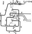
図2は、ディスペンサーの一部の動作の模式図である。
図3は、ディスペンサーの一部の分解斜視図である。
図4は、図1に示すディスペンサーの漂白剤のハウジングの斜視図である。
図5は、化学生成物を供給するのに用いられるパッケージの上面図である。
図6は、挿入直前のパッケージを有する漂白剤貯蔵部の断面図である。
図7は、漂白剤を供給するためのパッケージの分解斜視図である。
図8は、図1に示す注入マニホルドの斜視図である。
図9は、洗濯機上の注入マニホルドの断面図である。
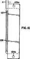
図10は、図8に示す注入マニホルドの底面図である。
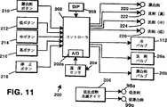
図11は、図2のディスペンサーに用いられる好適な制御システムのブロック図である。
図12は、図2のディスペンサーの好適なプログラムの流れを示すフローチャートである。
図13は、図12の生成物分配ルーチンの好適なプログラムを示すフローチャートである。
図14は、典型的な分配速度対希釈剤温度曲線のグラフである。
図15は、上方向に押された可撓性部材を示す、漂白剤貯蔵部の一部の部分拡大図である。
図16は、低レベル警報の図である。
好適な実施形態の詳細な説明
図面を参照すると、幾つかの図面において同様の番号は同様の部分を表し、ディスペンサーは、一般に100で表されている。電力が、適切な差込み口102に接続される電力コード101によってディスペンサー100に供給される。温水が、温水パイプ103を通してディスペンサー100に供給される。そして、温水パイプは、それに有効に取り付けられたT字形コネクタを有し、水インレット104が、ディスペンサー100に接続され、第2の水インレット105が、洗濯機106に接続されている。冷水は、冷水パイプ107を通して洗濯機106に供給される。使用希釈液アウトレットホース108が、ディスペンサー100と注入マニホルド109とを接続する。注入マニホルド109は、後に詳細に述べるように、洗濯機106に装着される。洗濯機106は、上面106aおよび蓋106bを有する。蓋106bは、典型的には、上面106aに対して蝶番式に動く。ほとんどの洗濯機には、後に詳細に述べるように、洗濯機の上面106aと蓋106bとの間には空間がある。
図2は、ディスペンサー100の動作の仕方の基本についての全体的なフローチャートを示す。ディスペンサーの一般的な動作については、ディスペンサー100の構造の詳細な説明の後に述べる。
温水インレット105は、調整器110および圧力ゲージ111を通して温水を供給する。メインソレノイド112が、ゲージ111に接続されている。さらに、サーミスター37が、ホース113を通り真空ブレーカー23へと流れる温水の流れと流体連通して設置されている。メインソレノイド弁112およびサーミスター37が、制御プロセッサ44と相互作用するときの動作については、後述する。真空ブレーカー23の他方の側において、ホース114がT字形部材30に接続されている。T字形部材30は、管115、116および117によってつながっている3つの排出口を有する。管115は、洗剤バルブ26aへの温水の流体連通を提供する。管117は、漂白剤バルブ26bへの温水の流体連通を提供する。管116は、フラッシュノズル40への温水の流体連通を提供する。洗剤ノズル10は、管115aによって洗剤バルブ26aと流体連通している。同様に、漂白剤ノズル9は、管117aによって漂白剤バルブ26bと流体連通している。液だめ33は、洗剤ノズル10、漂白剤ノズル9、またはフラッシュノズル40を通して与えられた使用希釈液または温水のいずれをも回収し、使用希釈液または温水は、重力によって液だめ33を出て使用希釈液アウトレットホース108へと運ばれる。
図8から図10を参照すると、洗濯機上面106aは、第1のほぼ平面の水平面120を有し、それは、第2のほぼ平面の水平面122と接続する下向きの面121に接続されている。これらの3面が組み合わさり、洗濯機の蓋106bがとどまるレッジが形成される。図示されるように、面121と蓋106bの端部との間に空間Gがある。さらに、面122と蓋106bの底部との間に少し小さな空間がある。
注入マニホルド109は、基部123および上面124を備えるハウジングを有する。基部123は、開口頂部を有する。上面124は、基部123の開口頂部に固定され、これにより、内部空洞125が形成される。基部および上面は、細長いマニホルドを形成し、一般に、直方体の箱を形成する。インレットコネクタ126が、上面124に接続され、内部空洞125と生成物アウトレットホース108との間の流体連通を可能にする。基部123は、アウトレット127を有する。アウトレット127は、長さが、好ましくは、少なくとも3インチの一般に細長いオリフィス128を有する。アウトレット127は、空間Gの幅より小さな幅Xを有する。典型的に、ほとんどの洗濯機におけるこの空間の幅は、少なくとも1インチの3/16または0.187インチである。0.18インチより小さな幅Xを有することによって、蓋106bがマニホルド109にぶつかることなく閉まる間隙ができる。オリフィス128の幅Oは、十分な使用希釈液がマニホルドを流れるように、0.05〜0.06インチであるのが好ましい。
基部123は、一般に細長い部材129が固定される底部123aを有する。マニホルド109は、洗濯機上に置かれ、定位置に保持される必要がある。図1は、洗濯機の上面106a上のマニホルド109を示す。洗濯機の上面にマニホルドを設置すると、蓋が開口位置に移動しても、マニホルドは移動しない。しかし、有利ではないとしても、マニホルドは蓋の上に設置され得ることが理解される。マニホルド109を洗濯機の上面106aに設置し固定するために、細長い部材129は、装着ネジが挿入され、洗濯機の上面106aにねじ込まれ得る2つの装着孔129aを備える。マニホルドを装着する他の適切な手段もまた利用され得ることが理解される。インレット126、基部123、上面124およびアウトレット127は、硬いプラスチックから構成され、一体化したユニットに組み立てるのが好ましい。細長い部材129は、装着孔129aが簡単に使用できるように基部123を超えて延びている。
図3は、ディスペンサーの分解斜視図を示す。図3の分解斜視図は、ホース接続を示していない。この接続に関しては、図2を参照するとよい。ホースアダプタかかり(barb)82が、温水インレット105を受け入れる。アダプタ82は、水圧調整器110に挿入され、水圧調整器は、套管93によってT字形部材90に接続される。圧力ゲージ111もまた、套管91によってT字形部材90に接続される。接管13もまた、T字形部材90に接続される、接管13は、シャーシー溶接部39上に装着されたコネクタ18に接続される。
ディスペンサーのハウジングは、上ハウジング1、下ハウジング2およびシャーシー溶接部39を含む。分解斜視図に見られるように、シャーシー溶接部39は、下ハウジング2の内側と嵌合する。次いで、上ハウジングが、シャーシー溶接部39の上に設置され、後に、ねじなどの適切な手段によって定位置に固定され得る。
接管20が、コネクタ18をメインソレノイド弁112に接続する。T字形部材36が、ソレノイド112に接続される。サーミスター37が、アダプタ95によりT字形部材36に接続される。T字形部材36の上部に、管コネクタ22が接続され、それに、エルボー24に接続されたホース113が接続される。エルボー24は、ナット35によって真空ブレーカー23に接続され、真空ブレーカー23は、真空ブレーカー23がシャーシー溶接部39に装着され得るようにブラケット23aを備える。別のエルボー24が、真空ブレーカー23に接続され、ホース114の一端が、エルボー24に接続し、ホース114のもう一端は、T字形部30に接続される。ホース114は、T字形部材30に対し温水インレットを提供し、T字形部材30は3つのアウトレットを有する。第1のアウトレットは、それに接続する減少連結部81を有する。そして、ホース115の一端が減少連結部81およびエルボー28aを介して洗剤バルブ26aに接続される。T字形部材30のもう1つの排出口は、ホース117の第1の端部が接続されるアダプタ29を有する。ホース117の第2の端部は、漂白剤バルブ26bに接続される。洗剤バルブ26aおよび漂白剤バルブ26bのいずれもブラケット26cおよび26dによってシャーシー溶接部に装着される。T字形部材30の第3の排出口には、コネクター81aが取り付けられている。ホース116の第1の端部は、コネクタ81aに接続され、ホース116の第2の端部はエルボー28bに接続され、エルボー28bは、スプレーノズル40に接続される。スプレーノズルは、液だめ33のインレット開口部に装着される。スプレーノズル40によって液だめ33の内部に入った水は、液だめアウトレット33aから出る。
上ハウジング1は、背面パネル1aおよびプラットフォーム1bを有する。プラットフォーム1bは、ほぼ平面であり、ほぼ水平である。しかし、プラットフォームには、ディスペンサーの前面の方向に向かってわずかのスロープがある。プラットフォーム1bに、2つの円形のリセプタクルが形成される。第1の円形リセプタクル140は、洗剤貯蔵部シリンダー74を受け入れるようなサイズになっている。洗剤貯蔵部74は、ほぼ円筒形である。洗剤貯蔵挿入部5もまた円筒形であり、洗剤貯蔵部74の内側に設置される。洗剤貯蔵挿入部5は、メッシュの底部5aを有する。洗剤カバー3が、蝶番4によって洗剤貯蔵挿入部5に接続される。第1の円形リセプタクル140は、井戸140bへの排出部として作用するための下方向のスロープ面140aを有する。井戸140bとメッシュ5aとの間に洗剤用ふるい94が設置される。井戸140bはアウトレット140cを有する。アウトレット140cは、管19aによって液だめ33に接続される。管締め具19bを用いて管19aをアウトレット140cおよび液だめ33に接続する。
上ハウジング1は、漂白剤貯蔵部6を受け入れるようなサイズの第2の円形リセプタクル150を有する。第2の円形リセプタクル150は、井戸150bへと下方向に排出するスロープ面150aを有する。井戸150bは、管19cによって液だめ33に接続されるアウトレット150cを有する。管19cは、両端に締め具19dを用いる。漂白剤用ふるい8が、スロープ面150aの上であって、スロープ面と漂白剤貯蔵部6との間に設置される。漂白剤貯蔵部6については後に詳細に述べる。近位リードスイッチ14aおよび14bが、それぞれ、装着ブラケット15aおよび15bによって、洗剤および漂白剤貯蔵部のカバーに隣接して装着される。ディスペンサーが動作する以前に、確実にカバーが下の位置にあるようにするために、近位リードスイッチが用いられる。
洗剤スプレーノズル10が、洗剤貯蔵部74に装着され、洗剤用ふるい94の中央の開口部を通って延びる。ノズルは、メッシュ5aの上の洗剤貯蔵挿入部5に貯蔵される洗剤に水をスプレーするように設置される。ノズル10は、ホース115aの一方の端部に接続するエルボー10aに接続される。ホース115aの他方の端部は、エルボー87に接続し、エルボー87は、洗剤バルブ26aと流体連通し接続される。同様に、漂白剤スプレーノズル9が、ふるい8の下に装着され、漂白剤貯蔵部6の漂白剤にスプレーするために設置される。これについては、後に詳細に述べる。漂白剤ノズル9は、エルボー9aに接続される。エルボー9aは、117aの一方の端部に接続される。ホース117aの他方の端部は、エルボー51に接続される。エルボー51は、漂白剤バルブ26bと流体連通し接続される。
図4〜図6および図15は、漂白剤貯蔵部およびパッケージをより詳細に示す。漂白剤貯蔵部6は、蝶番7aによってそれに装着されるカバー7を有する。漂白剤貯蔵部6は、ほぼ円形であり、円筒の形状を有する。漂白剤貯蔵部6の上部にはフランジ6aがある。フランジもまた円形であり、漂白剤貯蔵部6の一体化された部分として働くのが好ましい。フランジ部材6aは、開口頂部を形成する。漂白剤貯蔵部6自体が貯蔵部の内部空洞を形成する。漂白剤貯蔵部は、その開底端部に、スロープ面150aへと排出するアウトレットを有する。外側リング160は、その開口頂部近傍において漂白剤貯蔵部6と有効に接続される。リング160は、一般に、フランジ6aの一部を囲む。リングは、180度、好ましくは約270度より大きく延びることが好ましい。外側リング160のサイズは、フランジ6aより大きな直径である。
パッケージ170は、ほぼ円筒形の容器である。パッケージ170は、内側空洞170aおよび周囲の壁170bを有する。周囲の壁170bは、円形であり開口部を形成する。ダイアフラムまたは指状カラー部180が、周囲の壁170bに装着され、容器の開口部の一部を横切る。ダイアフラム180は、複数の可撓性部材または内側に延びる可撓性指状部185を有する。可撓性部材185は、適切なプラスチックなどの半剛直材料からなる。分配される漂白剤186が、パッケージ170の内側に入っている。漂白剤186もまた円筒形である。漂白剤の円周は、フランジ6aより小さいが、可撓性部材185の両端部の間の距離Dより大きい。これによって、可撓性部材185は、可撓性部材が通常の第1の位置にあるとき、漂白剤のタブレット186を支持する。しかし、先に述べたように、この部材は可撓性がある。すなわち、パッケージのねじトップ170cを取り外しパッケージを逆さにすると、可撓性部材185が漂白剤を容器内に保持する。そして、パッケージが漂白剤貯蔵部に置かれると、外側リング160の中心が、フランジ6aの上でパッケージ170の中心と一致する。パッケージが押し込まれると、フランジ6aが可撓性部材185の向きを上方向に変え、可撓性部材が第2の位置にあるときのより大きな直径にまで距離D’を増加させる。可撓性部材が上に押されると、漂白剤タブレット186もまた上に移動し、ついに、可撓性部材は、漂白剤186が貯蔵庫内に落下するのに十分なほどその向きを変える。その時、この増加した距離D’は、漂白剤タブレットの直径より大きいので、これにより、漂白剤貯蔵部6内に落下する。次いで、パッケージが取り外され、蓋7が閉じられる。図6は、パッケージ170の底部と漂白剤との間の空隙を示している。輸送中での漂白剤の破損を防止するために、発泡パッケージ挿入物を入れて空隙をなくすのが好ましい。あるいは、パッケージの高さを漂白剤の大きさとほぼ等しくするためにパッケージの底部を移動させ得る。
パッケージ170は、その円周のまわりに延びる複数のリブ170dを有する。リブは、長手方向にあり、これにより、パッケージをより容易に握ることができ、パッケージの取り扱いを容易にしている。
さらに、ディスペンサー100は、低生成物警報の特徴を備えている。この低生成物警報は漂白剤貯蔵部6および洗剤貯蔵部74に形成される視界口98および99からなる。同様に、発光ダイオード98aおよび99aが、上ハウジング1の後部に設置される。漂白剤および洗剤の警報システムは類似しているので、洗剤警報の動作の原理は類似していることが理解されることから、漂白剤警報について詳細に述べる。
図3および図16を参照すると、集束光源98aが、警報が現れることを望むレベルに装着されているのが見られる。光源の装着位置が高いほど、警報は早く作動する。好適な実施形態において、集束光源98aは、視野角が4度の発光ダイオード(LED)である。角度は、光の集束ビームが利用できるように少なくとも6度より小さいのが好ましい。さらに、LEDは、高強度LEDが好ましく、少なくとも10,000mcd、好ましくは13、000mcdの強度を有するのが好ましい。光の集束ビームは、透明な漂白剤貯蔵部の壁を通して輝く。光源は、漂白剤貯蔵部の反対側の壁に配置される視界口98とほぼ並んでいる。視界口は、1つの透明部または開口部のいずれかであるか、あるいは、光98aの様々な設置を可能にする複数の開口部であり得る。さらに、視界口98は、LED98aからの光の集束ビームが視界口に到達し、オペレータが、視界口を通して輝く光をより簡単に見ることができるように、ディフューザー98bを組み込んでもよい。すなわち、もし、視界口が、単に貯蔵部の透明な開口部である場合、オペレータは、光のビームを見るために、光のビームと並んで立つ傾向がある。しかし、ディフューザーが視界口に組み込まれていると、オペレータはある角度はずれて立つことができ、より簡単に光が見える。
光の色は、どんな色でもよいが、赤の光は、オペレータの注意力をより必要とすることが分かっている。さらに、後に詳細に述べるように、光はまた、低レベルを示す警告を高めるために点滅してもよい。
制御システム200の主要なハードウェア構成要素が、図11に示されている。制御システム200は、システムの主な動作を調整するコントローラ202を含む。コントローラ202は、マイクロプロセッサまたはマイクロコントローラ(例えば、Motorola MC68HC05マイクロコントローラまたはMicroChip PIC 16C7Xマイクロプロセッサ)などの、温度センサ204からアナログ温度信号を受信する内蔵アナログ−デジタルコンバータ202aを組み込んでいるものが好ましい。A/Dコンバータ202aは、所望であれば、分離した構成要素に実装してもよい。
温度センサ204は、サーミスター37(図2)などの低コスト装置を含み、電圧ディバイダ回路を介してA/Dコンバータ202aに連結され、希釈剤(水)温度を測定する。サーミスターを読む他の方法、例えば、感電圧タイミング回路を用いて可変幅のパルスをコントローラに与える方法を用いてもよい。
図2に示すように、希釈剤がディスペンサーに入ると、サーミスターが希釈剤温度を測定する。サーミスターは、ディスペンサー内の他の位置で希釈剤温度を測定してもよいし、希釈剤温度ではなく使用希釈液温度、またはディスペンサーの分配速度に影響を与える別の温度を測定しても構わない。
サーミスター以外の温度センサ装置もまた使用され得る。しかし、サーミスターは、一般に安価であり制御しやすく、従って、多くの低コスト応用での使用に適していると考えられている。
コントローラ202はまた、前面パネル199(図3)に配置された複数のボタンから幾つかの入力を受ける。漂白剤ボタン210により、オペレータは、洗剤とともに漂白剤を分配するかどうかを選択することができる。低洗剤ボタン212、中洗剤ボタン214および高洗剤ボタン216により、オペレータは、配送する生成物の3種類の投与量のうちの1つを選択することができる。停止ボタン218により、オペレータは、直ちにディスペンサーをリセットし、そのサイクルにおいてさらに分配するのを止めることができる。ボタン210〜218は、瞬時のプッシュボタンが好ましい。あるいは、ボタンの代わりに、他の入力装置、例えば、漂白剤または漂白剤なしを選択するスイッチ、あるいはアウトプット量を選択するための3方向スイッチまたはダイヤルおよび分配サイクルを開始するための別のボタンを用いてもよい。あるいは、他の入力構造を用いてもよい。
コントローラ202はまた、1組のDIPスイッチ203から構造情報を受信する。これらのスイッチは、非認可ユーザのアクセスを制限するためにハウジング内に配置するのが好ましい。
コントローラ202はまた、異なる装置を制御する。特定のサイクルが進行中のとき、一連の発光ダイオード(LED)、漂白剤LED220、洗剤(高)LED222、洗剤(中)LED224および洗剤(低)LED226が表示するように制御されてもよい。LEDは、ボタン210〜216と別個であってもよいし、そのボタン自体に組み込まれてもよい。コントローラ202はまた、水バルブ112、洗剤バルブ26aおよび漂白剤バルブ26b(図2)を、一連のリレー(図示せず)を用いて制御する。
図11はまた、前述のように、低洗剤アラームLED98aおよび低漂白剤アラームLED99aを点滅させるための点滅回路、低生成物点滅タイマ206を示す。タイマ206は、電力がディスペンサーに供給されている間、持続的に、1/2秒間隔でLED98aおよび99aを点滅させる555の直列タイマ回路を備えることが好ましい。LEDまたは他の発光装置を点滅させるタイマの使用は、当該技術分野で一般によく理解されているので、ここではこれ以上述べない。あるいは、コントローラ202は、LED98aおよび99aを制御する(例えば、所望であれば、生成物分配の間のみLEDを点滅させる)ために用いられ得る。
ディスペンサーを作動させるようにコントローラ202を構成するために、RAM、ROM、クロック発振器回路、電力供給回路、バッファ、ドライバなどを含む他の支持回路を必要とするかもしれない。しかし、典型的には、このような支持回路はプロセッサの種類によって様々であり、このような支持回路の使用について、当該分野においてよく理解されているので、ここではこれ以上述べない。
ディスペンサー100の好適な動作が、図12に主なルーチン250として示されている、コントローラ202によって実行される動作コードの好適なプログラムフローに示されている。ルーチン250は、ブロック252での開始から始まり、変数およびカウンタのリセット、定数の定義および他のハウスキーピング機能を含む幾つかの初期設定機能を行う。この時、幾つかのユーザが選択したオプション(好ましくは、ディスペンサー100のハウジング内に配置された一連のDIPスイッチ203(図11)を介して制御されたもの)もまた処理され得る。
好適な実施形態において、8個のDIPスイッチ(図11のブロック203に図示)が、異なる状況にあわせてディスペンサーをプログラムしたり、または適応させたりするのに用いられる。DIPスイッチの可能な設定を下の表Iに示す。
さらに、ブロック252において、閉鎖DIPスイッチもまたポーリングされ、閉鎖フラグを設定またはクリアする。閉鎖フラグは、洗剤および漂白剤の1回分の投与量が各サイクルで洗濯機に与えられるように、ディスペンサーの使用を5分に1回に制限したいときに設定される。
次いで、ルーチン250の主なプログラムループが、ブロック254から実行される。そこで、ボタンがオペレータによって押されるまでルーチンは待機する。ブロック254は、当該技術分野において公知のように、ボタン作動の有効性を確実にするために(例えば、オペレータに対し1秒間しっかりボタンを押すことを要求する)ディバウンス(debounce)ルーチンを含む。
一旦、ボタンが押されたことが検知されると、制御は、ブロック256に進み、どのボタンが押されたかを判断する。漂白剤ボタン210が押されたなら、制御は、ブロック258へ進み、漂白剤フラグを真(TRUE)に設定し、漂白剤LED220を作動させて漂白剤機能が選択されていることをオペレータに知らせる。ブロック258はまた、単に、各ボタンを押して漂白剤フラグおよびLEDを他方の状態に切り換え得る。これによって、漂白剤機能を選択した後、オペレータは考えを変えることができる。いずれにしても、次に、制御は、ブロック254に戻り、別のボタンが押されるのを待つ。
ブロック256に戻って、もし、低洗剤ボタン212、中洗剤ボタン214または高洗剤ボタン216が押されると、制御は、ブロック260に進み、サイクルを開始する。ブロック260は、押されたボタンに従って、上記のブロック252で得られた中洗剤投与量を、低、中または高スケーリングファクター(50%、100%または125%)によってスケーリングすることによって、分配する所望の投与量または量の洗剤(洗剤投与量)を設定する。次に、ブロック262において、もし、漂白剤フラグが設定されると、分配する所望の投与量または量の漂白剤(漂白剤投与量)が、上記のブロック252で概説したのと同じように、中漂白剤投与量をスケーリングすることによって、ブロック264で設定される。スケーリングファクターは、洗剤と漂白剤において同じであるのが好ましいが、異なっていてもよい。さらに、洗剤および漂白剤の1つまたは両方は、スケーリング可能でなくともよく、あるいは、各生成物ごとに別のレベルが選択されてもよい。
ブロック264の後、または、もし、漂白剤フラグが、設定されなかったら、制御は、ブロック266に進み、前フラッシュサイクルを開始する。このブロックでは、水バルブ112が開かれ、押されたボタンに対応するLED(すなわち、洗剤(低)LED226、洗剤(中)LED224または洗剤(高)LED222)が作動する。図2に示すように、バルブ26aおよび26bは閉じているので、バブル112を開くことにより、水はサーミスター37を通って、真空ブレーカー23およびライン113、114および116に進み、水はノズル28cを出て液だめ33に集まり、アウトレット108を通って洗濯機106へと排出される。
図12に戻って、次に、ブロック268は、前フラッシュ時間がくるまで(好ましくは約30秒間)待機する。前フラッシュの主要目的は、洗濯機内の衣類を湿らせ、高化学物質濃度による損傷を防ぐこと、および前フラッシュサイクルの終了時にディスペンサーが受ける水が、通常の動作温度になるように、水源から冷水を流し出すことである。
次に、生成物分配ルーチン270が、所望の投与量の洗剤(およびもし選択されれば)所望の投与量の漂白剤を分配するために実行される。ルーチン270が、図13に詳細に示されており、ブロック280において洗剤バルブ26aを開くこと、およびもし漂白剤フラグが設定さているなら、漂白剤バルブ26bを開くことから始まる。図2に示すように、バルブ26aを開くと、ライン114の水の一部は、ライン115に方向を換えノズル28aから出て、固体状の洗剤濃縮物にスプレーされ、そこから洗剤使用希釈液を形成する。それから、使用希釈液は、液だめ33に集まり、ノズル28cから出てくる水と混合され、アウトレット108を通って洗濯機106に通じる。同様に、バルブ26bを開くと、ライン114の水の一部は、ライン117に方向を換えノズル28bから出て、固体状の漂白剤濃縮物にスプレーされ、そこから漂白剤使用希釈液を形成する。これもまた、液だめ33に集まり、ノズル28cから出てくる水およびノズル28aからの洗剤使用希釈液と混合され、アウトレット108を通って洗濯機106に通じる。アウトレット108内へと通じる液体が、ノズル28a、28bおよび28cを出て液だめに集まる任意の液体からのディスペンサーのための最終使用希釈液を形成することを理解すべきである。
図13に戻ると、次に、ブロック282は、所定の期間(好ましくは、約2秒間)を待った後、分配された洗剤および漂白剤の走行総量の計算を開始する。その遅延は、バルブ26aおよび26bが開かれ、水がライン115および116を流れ、ノズル28aおよび28bを出て濃縮物にぶつかり、それらと使用希釈液を形成するまでの時間に伴う機械的遅延を表す。
次に、ブロック284において、洗剤および漂白剤の走行総量がリセットされる。次に、ブロック286において、水の現在の温度が、サーミスター37を用いて測定される。典型的に、サーミスターは、A/Dコンバータ202aでその出力電圧を捕らえ、それによって得られたデジタル値を読み出すことによって読み出される。
一旦、水の温度が得られると、洗剤および漂白剤の瞬間配送または分配速度は、特定の生成物の分配速度を温度に関連付けるコントローラ202に記憶された表から得られる。表は、所与のディスペンサーおよび生成物に対して実験に基づいて決定されるのが好ましい。一例として、図14は、約80〜140°Fの温度範囲での好適な洗剤ディスペンサーにおける、ある化学生成物、メタけい酸塩水化物、固体状のブロックランドリー洗剤の特徴的な分配速度曲線を示す。この表は、曲線を再現するのに必要な任意の数のデータ点を含み得るし、データ点の間の温度の分配速度を補間し得る。あるいは、最も近いデータ点が選択され得る。さらに、例えば、測定された温度を適切な等式に単に入れて瞬間分配速度を得るなどの、温度と分配速度を関連付ける曲線のあてはめまたは他の数学的分析などにより、等式が展開され得る。
図13に戻ると、瞬間配送速度の測定の後、ブロック290において、好適な実施形態では、好ましくは約0.25秒である、温度の測定時と測定時との間の時間(間隔時間)と瞬間配送速度とを掛けることによって、部分量または総量が計算される。それから部分量が走行総量(洗剤総量および漂白剤総量)に加算される。水の温度は短時間の間隔ではあまり変化しないことが知られており、従って、大変短い間隔時間は、応答における増分改良を提供するのみであり得る。他の応用において、異なる間隔時間が用いられ得る。
その結果、ブロック286〜290の動作は、一般に以下の等式に要約され得る。
DT=DT+IT*DetergentTable(Temp)
BT=BT+IT*BleachTable(Temp)
(ここで、DTおよびBTは、洗剤総量および漂白剤総量、ITは間隔時間、Tempは測定温度、DetergentTable(Temp)およびBleachTable(Temp)は、所与の測定温度の洗剤表および漂白剤表から取り出された瞬間配送速度である。)
次に、ブロック292において、漂白剤総量を漂白剤投与量と比較して、所望の量の漂白剤が分配されたかどうかを判断する。もし、分配されたのであれば、制御は、ブロック294に進み、漂白剤バルブ26bを閉じ、漂白剤LED220をオフにする。
次に、ブロック296において、洗剤総量を洗剤投与量と比較して、所望の量の洗剤が分配されたかどうかを判断する。もし、分配されたのであれば、ルーチンが完了し、制御は、図12のブロック272に戻る。もし、そうでなければ、制御は、ブロック298に進み、次の温度測定間隔がくるまで待機する。また、この間、押されたボタン(低、中または高)に対応する洗剤LED(222、224または226)および(選択されていれば)漂白剤LED220が明滅して、オペレータに生成物が分配されていることを知らせる。それから、制御は、ブロック286に戻り、次の温度測定を行う。
ブロック296もまた、最大分配時間(好ましくは、約120秒)が経過したかどうか調べる。もし、経過したのであれば、制御は、図12のブロック272に戻り、所定時間後、確実にディスペンサーは常に閉じる。好適な実施形態において、典型的に、洗剤投与量を分配するのに必要な時間は、漂白剤投与量を分配するのに必要な時間を超えることに注目すべきである。あるいは、もし、漂白剤または洗剤いずれかが分配に長い時間かかるなら、ブロック292および296は、どちらが先に分配されるかにかかわらず、適切な時間で確実に各バルブが閉まるように変更され得る。
図12のブロック272に戻って、生成物分配が完了すると、両方のバルブ26aおよび26bが閉じられ、それぞれのLEDがオフになる。次に、後フラッシュサイクルがブロック274において始まる。ここでは、水だけが(典型的には、約10秒間)ノズル28cからスプレーされ、液だめ33またはアウトレット108内のいかなる化学物質の残滓も洗い流される。
後フラッシュサイクルが完了すると、制御は、ブロック276に進み、水バルブ112を閉じ、分配サイクルを完了する。次に、制御は、ブロック278に進み、もし、このオプションがDIPスイッチ203に設定されているなら、システムを閉鎖する(好ましくは、約5分間)。もし、閉鎖期間が満了すると、または、このオプションが選択されないなら、制御は、ブロック254に戻り、新たにボタンが押されるのを待つ。
他の幾つかのプロセスが、コントローラ202において本発明に矛盾なく実行され得る。例えば、直ちにすべてのバルブを閉じシステムを停止させるために、中断駆動ルーチン(図示せず)によって停止ボタン218(図11)が押されるのが好ましい。また、専門家がコントローラをプログラムしたり更新できるように、別個のプログラムプロセスが実行されてもよい。さらに、コントローラは、データ収録および記録保存(例えば、各生成物に対して実行されたサイクルの数の記録)を行い得る。あるいは、他のプロセスが実行され得る。
本発明に矛盾することなく、好適なディスペンサーに対し様々な変更がなされ得る。例えば、希釈剤温度のサンプリングは、周期的間隔で行う必要はない。さらに、希釈剤温度以外の動作パラメータが、好適な実施形態によってモニターされ、補償され得る。他のタイプのディスペンサー、例えば、液体濃縮物と希釈剤とを混合するものもまた、本発明の原理を利用し得る。さらに、他の応用、例えば、化学生成物が希釈剤と混合されることなく配送される化学物質配送システム、ならびに化学生成物の粘度およびその配送速度がその温度によって変化するシステムも、本発明の原理を利用し得る。他の変更も当業者に明らかである。Background of the Invention
Field of Invention
The present invention relates generally to chemical dispensers in laundry operations, and more particularly, to chemical dispensers using pop-out chemical product packages, low level indicators, and temperature compensated controllers that vary dispenser dispense time in response to diluent temperature. .
Description of conventional technology
The use of dispensers to dispense solid products through the use of water or other diluents is well known in the art. Such a dispenser can be used for many purposes. One is to provide detergents and / or bleaches in the laundry operation. The problem arises when the operator has to handle or touch certain chemicals such as bleach. Usually, in order to put the bleach into the dispenser, the package containing the bleach must be inverted. In handling such bleach, it is difficult to keep the bleach inside the package while positioning the package over a suitable receptacle in the dispenser.
The present invention addresses such problems and provides a pop-out container for containing bleach or other similar products that are dangerous to handle, allowing the bleach to be removed and loaded into the dispenser. Use dispenser removal mechanism.
When the dispenser is activated and the use diluent is ready for use, the use diluent must be transported from the dispenser to the appropriate location for use. When such a dispenser is used with a washing machine, the most widely accepted method of connecting the drain tube and the washing machine is to perforate the sheet metal housing or hinged cover. A joint is then provided and the tube is connected to the joint. The joint can also be added by cutting or disassembling into the piping and / or cutting into the outer tub of the washing machine. These methods have negative consequences such as corrosion, hindrance to hinged cover operation, laundry breakage and internal liquid leakage. The present invention addresses the problems of the prior art, provides a chemical injection manifold that can be easily secured to the washing machine, and utilizes the space formed between the washing machine and the hinged lid.
Furthermore, a problem with dispensers that require refilling is the problem of notifying the operator that refilling is necessary because the chemical product level is low. There are many complex and expensive systems for performing this task. For example, an optoelectronic device that uses a light source directed at an optoelectronic sensor that controls an electrical signal, where the electrical signal informs the user by turning on an audio or video alarm. Other simpler devices have been used, such as simply illuminating the interior of the dispenser with light and then reducing the product level so that a scattered ray of light is visible through the viewing window. However, such a system is not very effective when it is difficult for the operator to see the light shining through the viewing port. Applicants have addressed the problems associated with conventional equipment and provided a simple and low-cost means to inform the operator that the dispenser will be refilled with chemicals by utilizing a high intensity condenser lamp. Yes.
Another problem seen throughout solid state chemical dispensers and other dispensers is precisely controlling the amount of chemical product dispensed. For example, some solid chemical dispensers use a conduction sensor to control the amount of product dispensed by monitoring the concentration of the chemical product in the working diluent. However, since such sensors are expensive and complex, their use in low cost applications may not be cost effective.
As an example, in some laundry applications, using a conduction sensor may not be cost effective. Thus, in these applications, low cost dispensers are often used that deliver a predetermined amount of a chemical product by assuming a constant delivery rate and operating the dispenser for a fixed period of time. However, it is known in the art that it is difficult or impossible to control many operating parameters that can change the actual dispensing speed of the dispenser. As the actual dispensing rate of the dispenser changes during operation, the total amount of chemical product delivered changes accordingly. In particular, in many laundry applications, if the actual dose of product delivered by the dispenser is low, cleaning and overall performance will be degraded. If the actual dosage of the product is high, excessive foaming can occur and chemical costs can increase.
One particular operating parameter that can affect the dispensing rate is the temperature of the diluent. In particular, in solid chemical dispensers where the diluent comes into contact with the solid chemical and dissolves the chemical to form a working diluent, the diluent temperature can have a significant impact on the distribution rate of the chemical product. Are known. There is no reliable way to control the total amount of product dispensed in a dispenser for a period of time without precisely controlling the diluent temperature, which is difficult if not impossible in the art. The present invention addresses this problem of the prior art and provides a dispenser device and method in which the dispenser dispensing time varies dynamically depending on the diluent temperature during dispenser operation.
Summary of the Invention
In one embodiment, the present invention is a chemical product injection manifold for use with a type of washing machine having an upper opening and a lid. The lid is smaller in size than the opening so as to form a space between the top and the lid. The manifold includes a fitting configured to receive a hose from a chemical dispenser. A housing having an internal cavity is in fluid communication with the joint. The housing also has a bottom. Means are also provided for positioning the manifold in the vicinity between the top of the washing machine and the lid. The positioning means is effectively connected to the housing. The outlet is in fluid communication with the cavity. The outlet is substantially elongated and has a width smaller than the width of the space.
In another embodiment, the present invention is a dispenser having a chemical product level indicator. The dispenser includes a housing having an internal cavity for storing the chemical product to be dispensed. A focused light source is placed at a location on the housing wall that matches the level of chemical product being detected. A viewing port is disposed on the opposite wall of the housing in substantial alignment with the focused light source, and the focused light is directed to the viewing port. When the chemical product level is above the line between the viewing port and the light source, the light is blocked from the viewing port, and when the product level decreases, the focused light source shines at the viewing port and is easily visible by the operator. obtain. In a preferred embodiment, the light source is a high intensity light emitting diode having a viewing angle of less than 6 degrees, preferably 4 degrees and an intensity of about 10,000 mcd or more.
In another embodiment, the present invention is a dispenser that dispenses a chemical product dissolved by a diluent. The dispenser includes a housing for receiving a chemical product. The housing has an internal cavity, an open top and an outlet. Means are also provided for spraying the diluent onto the solid material and dissolving the chemical product. A package supplies chemical products to the dispenser. The package comprises a container having an inner cavity including a peripheral wall defining an opening of the container and an open end. A diaphragm is attached to the surrounding wall and crosses a portion of the opening. The diaphragm has a plurality of flexible members extending inward. The flexible member is made of a semi-rigid material and has a size that prevents removal of chemical products when in the first position. When the flexible member is repositioned away from the center of the container to the second position, the flexible member no longer prevents removal of chemical products. A flange member is mounted near the top of the opening of the housing. The flange member is sized and configured to move the flexible member from the first position to the second position when the package is placed over the flange, and the chemical product is transferred from the container to the housing cavity. Fall into
In another embodiment, the present invention is a dispenser apparatus and method in which the dispense time of the dispenser dynamically changes depending on the temperature of the diluent during operation of the dispenser. By dynamically monitoring the temperature while the dispenser is operating and updating the dispensing time, changes in diluent temperature can be compensated between dispensing cycles and within individual dispensing cycles, This improves the distribution accuracy. A low cost temperature sensor such as a thermistor can be used to monitor the diluent temperature at periodic intervals. A table or equation relating dispenser dispense rate for a given product to diluent temperature is the instantaneous dispense rate at each interval, and the amount or dose of chemical product delivered during that interval at the instant dispense rate. It can be accessed to determine a partial amount or dose representing the amount. The partial amount is such that the total amount or dose of product dispensed is maintained at the total running amount by adding the previous partial amount to the total running amount. The dispenser can be closed when the total running amount reaches the desired amount or dose of delivery product.
Thus, according to one aspect of the present invention, a dispenser that accepts a diluent, discharges a use diluent containing a chemical product that is diluted by the diluent, and the dispensing rate of the chemical product varies with the temperature of the diluent; A temperature sensor that senses the temperature of the diluent and outputs a temperature signal representative of it, and is connected to the dispenser and the temperature sensor so that the dispenser dispenses an amount of working diluent having a predetermined amount of chemical product A dispenser device comprising a controller that is actuated to dynamically change a dispenser dispense time while the dispenser dispenses a working diluent in response to a temperature signal and delivers a predetermined amount of chemical product. To do.
According to another aspect of the present invention, in a dispenser of the type in which the chemical product is diluted with a diluent and discharged as a working diluent, the dispensing rate of the chemical product varies with the temperature of the diluent, a predetermined amount A method of dispensing the chemical product of is provided. The method includes the steps of initiating discharge of the use diluent from the dispenser, monitoring the diluent temperature when the dispenser discharges the use diluent, and the chemical dispensed from the dispenser using the diluent temperature. Calculating the total running amount of the product, and stopping discharging the used diluent from the dispenser when the total running amount is equal to a predetermined amount.
[Brief description of the drawings]
FIG. 1 is a perspective view of a dispenser of the present invention used with a washing machine.
FIG. 2 is a schematic view of part of the operation of the dispenser.
FIG. 3 is an exploded perspective view of a part of the dispenser.
FIG. 4 is a perspective view of the bleach housing of the dispenser shown in FIG.
FIG. 5 is a top view of a package used to supply chemical products.
FIG. 6 is a cross-sectional view of a bleach reservoir having a package just prior to insertion.
FIG. 7 is an exploded perspective view of a package for supplying bleach.
8 is a perspective view of the injection manifold shown in FIG.
FIG. 9 is a cross-sectional view of the injection manifold on the washing machine.
FIG. 10 is a bottom view of the injection manifold shown in FIG.
FIG. 11 is a block diagram of a preferred control system for use with the dispenser of FIG.
FIG. 12 is a flowchart showing a preferred program flow of the dispenser of FIG.
FIG. 13 is a flowchart illustrating a preferred program for the product distribution routine of FIG.
FIG. 14 is a graph of a typical dispensing rate versus diluent temperature curve.
FIG. 15 is a partial enlarged view of a portion of the bleach reservoir, showing the flexible member pushed upward.
FIG. 16 is a diagram of a low level alarm.
Detailed Description of the Preferred Embodiment
Referring to the drawings, like numerals represent like parts in the several views, and dispensers are generally designated 100. Power is supplied to the
FIG. 2 shows an overall flowchart for the basics of how the
The
Referring to FIGS. 8-10, the washing machine top surface 106a has a first generally planar
The
The base 123 generally has a bottom 123a to which an
FIG. 3 shows an exploded perspective view of the dispenser. The exploded perspective view of FIG. 3 does not show the hose connection. Refer to FIG. 2 for this connection. A hose adapter bar (barb) 82 receives the
The dispenser housing includes an
A connecting
The
The
A
FIGS. 4-6 and 15 show the bleach reservoir and package in more detail. The
The
Furthermore, the
Referring to FIGS. 3 and 16, it can be seen that the focused light source 98a is mounted at a level where an alarm is desired to appear. The higher the light source mounting position, the faster the alarm is activated. In a preferred embodiment, the focused light source 98a is a light emitting diode (LED) with a viewing angle of 4 degrees. The angle is preferably less than at least 6 degrees so that a focused beam of light is available. Further, the LED is preferably a high intensity LED, preferably having an intensity of at least 10,000 mcd, preferably 13,000 mcd. A focused beam of light shines through the walls of the clear bleach reservoir. The light source is generally aligned with a
The color of the light can be any color, but red light has been found to require more operator attention. Further, as will be described in detail later, the light may also flash to increase the warning indicating a low level.
The main hardware components of the
The
As shown in FIG. 2, when the diluent enters the dispenser, the thermistor measures the diluent temperature. The thermistor may measure the diluent temperature at other locations within the dispenser, or it may measure the diluent temperature used rather than the diluent temperature, or another temperature that affects the dispenser dispensing rate. Absent.
Temperature sensor devices other than thermistors can also be used. However, thermistors are generally inexpensive and easy to control and are therefore considered suitable for use in many low-cost applications.
The
The
The
FIG. 11 also shows a flash circuit, low
Other support circuitry including RAM, ROM, clock oscillator circuitry, power supply circuitry, buffers, drivers, etc. may be required to configure
The preferred operation of the
In a preferred embodiment, eight DIP switches (shown in
Further, at
The main program loop of routine 250 is then executed from
Once it is detected that a button has been pressed, control proceeds to block 256 to determine which button has been pressed. If the
Returning to block 256, if the
After
Returning to FIG. 12, block 268 then waits until the pre-flash time (preferably about 30 seconds). The main purpose of the pre-flush is to moisten the clothes in the washing machine, prevent damage from high chemical concentrations, and to ensure that the water received by the dispenser at the end of the pre-flush cycle is at a normal operating temperature from the water source. It is to flush out.
A product dispensing routine 270 is then performed to dispense the desired dosage of detergent (and if selected) the desired dosage of bleach.
Returning to FIG. 13, block 282 then waits for a predetermined period (preferably about 2 seconds) before starting to calculate the total amount of dispensed detergent and bleach run. The delay is a mechanical delay over time until
Next, at
Once the temperature of the water is obtained, the instantaneous delivery or dispensing rate of the detergent and bleach is obtained from a table stored in the
Returning to FIG. 13, after the instantaneous delivery rate measurement, at
As a result, the operation of blocks 286-290 can generally be summarized in the following equation:
DT = DT + IT*DetergentTable (Temp)
BT = BT + IT*BleachTable (Temp)
(Where DT and BT are the total amount of detergent and bleach, IT is the interval time, Temp is the measurement temperature, DetergentTable (Temp) and BleachTable (Temp) are from the detergent and bleach tables at a given measurement temperature. (Instant delivery speed when taken out.)
Next, at
Next, at
Block 296 also checks to see if the maximum dispensing time (preferably about 120 seconds) has elapsed. If so, control returns to block 272 of FIG. 12 to ensure that the dispenser always closes after a predetermined time. It should be noted that in a preferred embodiment, typically the time required to dispense a detergent dose exceeds the time required to dispense a bleach dose. Alternatively, if either bleach or detergent takes a long time to dispense,
Returning to block 272 of FIG. 12, when product dispensing is complete, both
When the post-flush cycle is complete, control proceeds to block 276 where the
Several other processes may be performed in the
Various modifications can be made to a suitable dispenser without departing from the present invention. For example, sampling of the diluent temperature need not occur at periodic intervals. Furthermore, operating parameters other than diluent temperature can be monitored and compensated for by the preferred embodiment. Other types of dispensers, such as those that mix liquid concentrates and diluents, may also utilize the principles of the present invention. In addition, other applications, such as a chemical delivery system in which the chemical product is delivered without being mixed with a diluent, and a system in which the viscosity of the chemical product and its delivery rate change with its temperature are also of the present invention. The principle can be used. Other modifications will be apparent to those skilled in the art.
Claims (9)
Translated fromJapanese(a)内部空洞、開口頂部およびアウトレットを有する、前記化学生成物を受け入れるためのハウジングと、
(b)前記化学生成物を溶解するために、前記化学生成物に前記希釈剤をスプレーする手段と、
(c)前記化学生成物を前記ディスペンサーへ供給するためのパッケージであって、前記パッケージは、
(i)容器の開口部を規定する周囲の壁を含む内部空洞および開口端部を有する容器と、
(ii)前記周囲の壁に装着され、前記開口部の一部を横切り、内側に向かって延びる複数の可撓性部材を有するダイアフラムとを備え、
(iii)前記可撓性部材は、半剛直材料からなり、第1の位置にあるとき、前記化学生成物の除去を阻止する大きさを有し、
(iv)前記可撓性部材は、前記容器の中心から離れて第2の位置へと位置を変えるように形成され、前記可撓性部材が前記第2の位置にあるとき、もはや前記化学生成物の除去を阻止しない、パッケージと、
(d)前記ハウジングの前記開口頂部近傍に装着されるフランジ部材であって、前記パッケージがフランジ部材の上に置かれると前記可撓性部材を前記第1の位置から前記第2の位置に移動させるような大きさおよび構成を有し、それから、前記化学生成物が、前記容器から前記ハウジングの前記内部空洞へと落下させるようなフランジ部材と、
(e)前記ハウジングの壁の、検知される固体材料としての前記化学生成物のレベルに合った位置に配置される集束光源と、
(f)前記ハウジングの反対側の壁に配置され、前記集束光源とほぼ並んでいる視界口と、
(g)前記視界口に組み込まれたディフューザーと
を備え、
前記集束光源からの光は前記視界口に向けられ、前記化学生成物のレベルが、前記視界口と前記集束光源との間のラインよりも上であるとき、前記集束光源からの前記光は前記視界口から遮断され、前記化学生成物のレベルが下がると、前記集束光源からの前記光は前記視界口に到達することを特徴とするディスペンサー。A dispenser for dispensing a chemical productas a solid material which is dissolved by the diluent,
(A) a housing for receivingsaid chemical product, having an internal cavity, an open top and an outlet;
(B) to dissolvethe chemical product, and means for sprayingsaid diluent tosaid chemical products,
(C) asaid chemical product a package to be supplied tothe dispenser, said package,
(I) a container having an internal cavity including a peripheral wall defining an opening of the container and an open end;
(Ii)the mounted around the wall, across a portion ofthe opening, and a diaphragm having a plurality of flexible members extending inwardly,
(Iii) wherein the flexible member is made of semi-rigid material, when in the first position, has a size which prevents the removal ofthe chemical product,
(Iv) wherein the flexible member is formed to change the position to the second position away from the center ofthe container,when said flexible memberis in the second position, no longerthe chemical product have preventedShinano the removal of objects, and the package,
And (d) a flange member mounted tothe vicinity of the opening top ofsaid housing, movingthe flexible member andthe package is placed on the flangemember tosaid second position fromsaid first position sized and configured to be, then,the chemical product, a flange member that so thatis dropped fromthe container tothe internal space sinus ofsaid housing,
(E) a focused light source disposed at a position on the wall of the housing that matches the level of the chemical product as the solid material to be detected;
(F) a viewing port disposed on the opposite wall of the housing and substantially aligned with the focused light source;
(G) a diffuser incorporated in the viewing port;
The light from the focused light source is directed to the viewing port, and when the chemical product level is above the line between the viewing port and the focused light source, the light from the focused light source is is blocked from view port, when the level of the chemical product falls, the light from the focused light source you characterized in that to reach it said viewing port dispenser.
(a)前記ディスペンサーからホースを受け入れるように形成された継ぎ手と、
(b)前記継ぎ手と流体連通している内部空洞を有し、底部を有するマニホルドハウジングと、
(c)前記マニホルドを前記洗濯機の前記上部と前記蓋との間の空間の近傍に位置決めする手段であって、前記マニホルドハウジングに有効に接続される位置決め手段と、
(d)前記内部空洞と流体連通し、ほぼ細長く、前記空間の幅よりも小さな幅を有するアウトレットと、
を備えた請求項1に記載のディスペンサー。Further comprising together using chemical product inlet manifold type washing machine having an opening and a lid at the top,the lid is smaller in sizethanthe opening so as to form a space betweenthe upper andthe lid And the manifold is
A joint formed to receive a hose from (a)the dispenser,
(B) amanifold housing having an inner cavity in fluid communication with the joint and having a bottom;
And means for positioning in the vicinity of the space between the (c) said manifold andsaid upper portion ofsaid washer andsaid lid, and positioning means operatively connected to saidmanifold housing,
(D) passing saidinternal cavity in fluid communication with an outlet having a substantially elongated, smaller widththan the width of the space,
Dispenser according to請 Motomeko 1having a.
(b)前記希釈剤の温度を検知し、それを表す温度信号を出力する温度センサーと、
(c)前記ディスペンサーおよび前記温度センサーに連結され、所定の量の前記化学生成物を有する前記使用希釈液の量を分配するように前記ディスペンサーを作動させ、前記ディスペンサーが、前記温度信号に応じて前記使用希釈液を分配し、前記化学生成物の所定の量を配送している間、前記ディスペンサーの分配時間を動的に変化させる、コントローラと、
をさらに備えた請求項1に記載のディスペンサー。(A) receivingthe diluent, a dispenser for discharging the used diluent containingthesaid chemical product dilutedI by the diluent dispensing rate ofthe chemical product dispenser ofthe diluent A dispenser that changes with temperature,
(B) detecting the temperature ofthe diluent, a temperature sensor for outputting a temperature signal representative thereof,
(C) is connected tothe dispenser andthe temperature sensor to actuatethe dispenser to dispense an amount ofthe used diluent havingthe chemical product of a predetermined amount,the dispenser, depending onthe temperature signalthe use distributes the diluent, while delivering a predetermined amount ofthe chemical products, dynamically changing the distribution time ofthe dispenser, and a controller,
A dispenser according to claim 1,further comprising a.
Applications Claiming Priority (3)
| Application Number | Priority Date | Filing Date | Title |
|---|---|---|---|
| US08/644,620 | 1996-05-06 | ||
| US08/644,620US5782109A (en) | 1996-05-06 | 1996-05-06 | Dispenser |
| PCT/US1996/019694WO1997042370A1 (en) | 1996-05-06 | 1996-12-13 | Dispenser |
Publications (2)
| Publication Number | Publication Date |
|---|---|
| JP2001519685A JP2001519685A (en) | 2001-10-23 |
| JP3928667B2true JP3928667B2 (en) | 2007-06-13 |
Family
ID=24585673
Family Applications (1)
| Application Number | Title | Priority Date | Filing Date |
|---|---|---|---|
| JP53989097AExpired - LifetimeJP3928667B2 (en) | 1996-05-06 | 1996-12-13 | dispenser |
Country Status (12)
| Country | Link |
|---|---|
| US (2) | US5782109A (en) |
| JP (1) | JP3928667B2 (en) |
| AU (1) | AU707267B2 (en) |
| BR (1) | BR9609385A (en) |
| CA (1) | CA2219227C (en) |
| DE (1) | DE19681479B4 (en) |
| FR (3) | FR2748280B1 (en) |
| GB (1) | GB2318129B (en) |
| IT (1) | IT1304966B1 (en) |
| MX (1) | MX9800224A (en) |
| WO (1) | WO1997042370A1 (en) |
| ZA (1) | ZA9610925B (en) |
Families Citing this family (76)
| Publication number | Priority date | Publication date | Assignee | Title |
|---|---|---|---|---|
| DE19654090C1 (en)* | 1996-12-23 | 1998-03-05 | Henkel Ecolab Gmbh & Co Ohg | Washing machine detergent feed |
| US5975352A (en)* | 1997-08-28 | 1999-11-02 | Ecolab Inc. | Dispenser |
| US6240953B1 (en) | 1998-04-13 | 2001-06-05 | Sunburst Chemicals, Inc. | Multiple cleaning chemical dispenser |
| US6006388A (en)* | 1998-04-14 | 1999-12-28 | Young; Cecil Blake | Dispenser for dispensing concentrated liquid soap to industrial cleaning apparatuses |
| US6213353B1 (en)* | 1998-10-05 | 2001-04-10 | Dema Engineering Company | Solid bowl feeder and equipment tray assembly |
| DE19852164A1 (en)* | 1998-11-12 | 2000-05-25 | Lang Apparatebau Gmbh | Method and device for detecting the quantity of a product dissolved in a solution stream |
| US6138693A (en)* | 1998-11-23 | 2000-10-31 | Matz; Warren W. | Automatic detergent dispenser |
| US6737028B1 (en) | 1999-06-02 | 2004-05-18 | Sunburst Chemicals, Inc. | Solid cast container |
| US6375041B1 (en)* | 1999-09-28 | 2002-04-23 | Sunpat L.L.C. | Rechargeable dispensing device |
| US6178987B1 (en)* | 1999-11-10 | 2001-01-30 | Eco-Safe, L.L.C. | Autonomous cleaning mechanism |
| US6403551B1 (en) | 1999-11-10 | 2002-06-11 | Eco-Safe, L.L.C. | Autonomous cleaning apparatus and method |
| US7053040B2 (en)* | 1999-11-10 | 2006-05-30 | Eco-Safe Technologies, L.L.C. | Autonomous cleaning composition and method |
| US20050130868A1 (en)* | 1999-11-10 | 2005-06-16 | Evans K D. | Multiuse, solid cleaning device and composition |
| US6773668B1 (en)* | 2000-04-17 | 2004-08-10 | Ecolab, Inc. | Detergent dispenser |
| AU2001258368A1 (en) | 2000-04-25 | 2001-11-07 | Shell Internationale Research Maatschappij B.V. | Process and machine for mixing liquids |
| EP1276683A1 (en)* | 2000-04-25 | 2003-01-22 | Shell Internationale Researchmaatschappij B.V. | Product delivery system |
| MXPA02010508A (en)* | 2000-04-25 | 2003-05-14 | Shell Int Research | Process for the customisation of consumer products. |
| IT1320212B1 (en)* | 2000-06-22 | 2003-11-26 | Eltek Spa | DEVICE DISPENSER OF WASHING AGENTS FOR A DOMESTIC WASHING MACHINE, IN PARTICULAR A DISHWASHER. |
| US6645924B2 (en) | 2001-04-09 | 2003-11-11 | Ecolab Inc. | Device and method for generating a liquid detergent concentrate from a solid detergent and a method for washing a vehicle |
| US6662600B1 (en) | 2002-08-07 | 2003-12-16 | Tennant Company | Foamed cleaning liquid dispensing system |
| US20030201282A1 (en)* | 2001-12-19 | 2003-10-30 | Floyd Timothy H. | Systems and methods for producing and dispensing automobile appearance care products |
| US20040065682A1 (en)* | 2001-12-19 | 2004-04-08 | Floyd Timothy H. | Apparatus for producing and dispensing selected amounts of automobile appearance care products |
| US20040060946A1 (en)* | 2001-12-19 | 2004-04-01 | Floyd Timothy H. | Apparatus with selected features for producing and dispensing automobile appearance care products |
| US20040065675A1 (en)* | 2001-12-19 | 2004-04-08 | Floyd Timothy H. | Apparatus for producing and dispensing automobile appearance care products |
| US20040065681A1 (en)* | 2001-12-19 | 2004-04-08 | Floyd Timothy H | Apparatus in selected housings for producing and dispensing automobile appearance care products |
| US6978911B2 (en)* | 2001-12-19 | 2005-12-27 | Auto Wax Company, Inc. | Apparatus and methods for producing and dispensing automobile appearance care products charged to a customer on a selected bases |
| US20040206778A1 (en)* | 2001-12-19 | 2004-10-21 | Floyd Timothy H | Apparatus for producing and dispensing selected automobile appearance care products |
| US6988637B2 (en)* | 2001-12-19 | 2006-01-24 | Auto Wax Company, Inc. | Apparatus and methods for a customer to produce and dispense automobile appearance care products |
| JP4017504B2 (en)* | 2002-11-19 | 2007-12-05 | シャープ株式会社 | Washing machine |
| US6994271B2 (en) | 2003-09-22 | 2006-02-07 | Ecolab, Inc. | Automated chemical application system and method |
| US20050072195A1 (en)* | 2003-10-02 | 2005-04-07 | Laundrox, Inc. | Chemical dispenser |
| US20050133622A1 (en)* | 2003-12-19 | 2005-06-23 | Johnsondiversey, Inc. | Support for dispensing device |
| US7090098B2 (en)* | 2004-05-06 | 2006-08-15 | Johnsondiversey, Inc. | Metering and dispensing closure |
| US7597861B2 (en)* | 2004-10-18 | 2009-10-06 | Ecolab Inc. | Method and apparatus to control dispensing rate of a solid product with changing temperature |
| PL2216089T3 (en)* | 2004-10-18 | 2013-03-29 | Ecolab Inc | Solid product dispenser |
| CA2785929C (en)* | 2004-10-18 | 2013-01-29 | Ecolab Inc. | Solid product dispenser and method and apparatus to control dispensing rate of a solid product with changing temperature |
| AU2004325528B2 (en)* | 2004-12-09 | 2009-07-23 | Ecolab Inc. | Detergent dispenser |
| US7658088B2 (en) | 2005-03-03 | 2010-02-09 | Knight, Llc | Modular dual-purpose chemical dispensing system for laundry or warewash |
| DE102005050083B4 (en)* | 2005-10-18 | 2011-11-03 | Miele & Cie. Kg | Dosing device for liquid additive for a household appliance |
| US20080028802A1 (en)* | 2006-08-01 | 2008-02-07 | Glenn Thomas Jordan | Receiving apparatus |
| DE102007028214A1 (en)* | 2007-06-20 | 2008-12-24 | BSH Bosch und Siemens Hausgeräte GmbH | Automatically controlled washing machine |
| ATE497046T1 (en)* | 2007-07-03 | 2011-02-15 | Electrolux Home Prod Corp | WASHING MACHINE |
| JP2010537787A (en) | 2007-09-07 | 2010-12-09 | ディバーシー・インコーポレーテッド | Material supply system and method |
| US7802335B2 (en) | 2007-10-12 | 2010-09-28 | General Electric Company | Bulk dispense user adjustable controls |
| US8056374B2 (en)* | 2007-10-12 | 2011-11-15 | General Electric Company | Multiple compartments wash additives auto-dispenser in washer or dryer pedestal |
| US8056747B2 (en)* | 2007-10-12 | 2011-11-15 | General Electric Company | Removable tank for laundry bulk dispenser system |
| US8002898B2 (en)* | 2007-12-19 | 2011-08-23 | Diversey, Inc. | Material delivery systems and methods |
| ITPD20080006U1 (en)* | 2008-02-05 | 2009-08-06 | Carel S P A | "BOILER DEVICE, PARTICULARLY FOR HUMIDIFIERS" |
| IT1390915B1 (en)* | 2008-07-24 | 2011-10-19 | Indesit Co Spa | WASHING MACHINE INCLUDING A DRAWER FOR WASHING AGENTS |
| DE102009028588A1 (en)* | 2009-08-17 | 2011-02-24 | BSH Bosch und Siemens Hausgeräte GmbH | Water-conducting household appliance |
| DE102009029441A1 (en)* | 2009-09-14 | 2011-03-24 | BSH Bosch und Siemens Hausgeräte GmbH | Water-bearing household appliance with several dosing tanks |
| KR101698310B1 (en)* | 2009-12-24 | 2017-01-20 | 삼성전자주식회사 | Detergent supply apparatus and washing machine having the same |
| USD658343S1 (en)* | 2010-09-16 | 2012-04-24 | Lg Electronics Inc. | Detergent box for washing machine |
| US8844156B2 (en) | 2010-12-14 | 2014-09-30 | Whirlpool Corporation | Laundry treating appliance with purged chemistry conduits |
| KR20120082989A (en) | 2011-01-17 | 2012-07-25 | 삼성전자주식회사 | Washing machine |
| US9364798B2 (en)* | 2013-08-15 | 2016-06-14 | Applied Silver, Inc. | Antimicrobial batch dilution system |
| US11618696B2 (en) | 2013-08-15 | 2023-04-04 | Applied Silver, Inc. | Antimicrobial batch dilution system |
| US10640403B2 (en) | 2013-08-15 | 2020-05-05 | Applied Silver, Inc. | Antimicrobial batch dilution system |
| US10000881B2 (en) | 2013-12-06 | 2018-06-19 | Applied Silver, Inc. | Method for antimicrobial fabric application |
| US9850060B2 (en)* | 2014-08-05 | 2017-12-26 | Ecolab Usa Inc. | Multiple solid products liquid solution dispenser |
| US10549245B2 (en) | 2014-08-05 | 2020-02-04 | Ecolab Usa Inc. | Apparatus and method for dispensing solutions from solid products |
| US20170050870A1 (en) | 2015-08-21 | 2017-02-23 | Applied Silver, Inc. | Systems And Processes For Treating Textiles With An Antimicrobial Agent |
| DE102015116919A1 (en)* | 2015-10-06 | 2017-04-06 | Miele & Cie. Kg | Washing machine with a device for the supply of liquid and dosing device for liquid |
| KR102450182B1 (en)* | 2016-01-05 | 2022-10-04 | 엘지전자 주식회사 | Laundry treating apparatus and mehtod for supplying washing agent thereof |
| US20200123700A1 (en) | 2017-03-01 | 2020-04-23 | Applied Silver, Inc. | Systems and processes for treating textiles with an antimicrobial agent |
| IT201700068560A1 (en)* | 2017-06-20 | 2018-12-20 | F Lab S R L | MIXING AND DOSING EQUIPMENT FOR DETERGENT PRODUCTS. |
| DE102017123519A1 (en)* | 2017-10-10 | 2019-04-11 | Miele & Cie. Kg | Washing machine and method for displaying a level of a detergent container in a washing machine |
| USD865306S1 (en) | 2017-12-21 | 2019-10-29 | Whirlpool Corporation | Laundry treating appliance door |
| USD848692S1 (en) | 2017-12-21 | 2019-05-14 | Whirlpool Corporation | Bulk dispensing drawer |
| USD877431S1 (en) | 2017-12-21 | 2020-03-03 | Whirlpool Corporation | User interface |
| USD874764S1 (en) | 2017-12-21 | 2020-02-04 | Whirlpool Corporation | User interface |
| USD866887S1 (en) | 2017-12-21 | 2019-11-12 | Whirlpool Corporation | Pedestal |
| USD899720S1 (en) | 2017-12-21 | 2020-10-20 | Whirlpool Corporation | Laundry treating appliance |
| CA3091132A1 (en) | 2018-02-13 | 2019-08-22 | Ecolab Usa Inc. | Portable solid product dispenser and use thereof, and method of dispensing a solution of a fluid and a solid product |
| EP4509648A3 (en)* | 2021-01-04 | 2025-05-14 | Miele & Cie. KG | Metering device |
| BE1028985B1 (en)* | 2021-01-04 | 2022-08-03 | Miele & Cie | dosing device |
Family Cites Families (43)
| Publication number | Priority date | Publication date | Assignee | Title |
|---|---|---|---|---|
| US2431121A (en)* | 1944-11-09 | 1947-11-18 | Melmoth W Hunter | Token or like dispensing device |
| GB603092A (en)* | 1945-04-17 | 1948-06-09 | John Gibbs Carline | Improvements in or relating to containers for use in delivering articles individually |
| US2957503A (en)* | 1958-10-21 | 1960-10-25 | John J Stifter | Pill dispenser |
| DE1403674A1 (en)* | 1961-02-22 | 1968-10-24 | Siemens Elektorgeraete Gmbh | Dosing device for dishwashers and washing machines |
| FR1324514A (en)* | 1962-04-27 | 1963-04-19 | Diamond Power Speciality | Observation device for association with a two-color multi-lumen liquid level gauge intended to indicate the water level in high pressure steam boilers |
| US3306493A (en)* | 1964-08-24 | 1967-02-28 | Continental Can Co | Dispensing container |
| US3637109A (en)* | 1969-11-12 | 1972-01-25 | John J Stifter | Dispensing devices |
| US4129230A (en)* | 1975-01-06 | 1978-12-12 | Fmc Corporation | Tablet dispenser |
| US3990272A (en)* | 1975-06-23 | 1976-11-09 | General Electric Company | Washing machine with improved additive dispensing means |
| US4063663A (en)* | 1975-12-15 | 1977-12-20 | Economics Laboratory, Inc. | Powdered detergent dispenser |
| US4250911A (en)* | 1979-09-28 | 1981-02-17 | Kratz David W | Chemical feeder with disposable chemical container |
| US4408700A (en)* | 1981-05-28 | 1983-10-11 | Owens-Illinois, Inc. | Multi-part dispensing closure having a frangible connecting web |
| DE3240047A1 (en)* | 1982-10-28 | 1984-05-03 | Bosch-Siemens Hausgeräte GmbH, 7000 Stuttgart | Device in washing machines or dishwashers |
| DE3240048A1 (en)* | 1982-10-28 | 1984-05-03 | Bosch-Siemens Hausgeräte GmbH, 7000 Stuttgart | Device in washing machines having detergent storage containers |
| US4528709A (en)* | 1983-12-07 | 1985-07-16 | Whirlpool Corporation | Automatic temperature control for automatic washers |
| DE3518645A1 (en)* | 1985-05-23 | 1986-11-27 | Knebel & Röttger GmbH & Co, 5860 Iserlohn | METHOD AND CIRCUIT ARRANGEMENT FOR CONTROLLING A SANITARY MIXER BATTERY FOR COLD AND HOT WATER |
| US4858449A (en)* | 1986-01-09 | 1989-08-22 | Ecolab Inc. | Chemical solution dispenser apparatus and method of using |
| US4687121A (en)* | 1986-01-09 | 1987-08-18 | Ecolab Inc. | Solid block chemical dispenser for cleaning systems |
| US5007559A (en)* | 1986-07-21 | 1991-04-16 | Young Cecil B | Method and apparatus for dispensing a particulate material |
| US4836229A (en)* | 1987-04-30 | 1989-06-06 | Ecolab Inc. | Dishwashing apparatus including a flip-top solid detergent dispenser |
| US4938240A (en)* | 1987-04-30 | 1990-07-03 | Ecolab Inc. | Dishwashing apparatus including a flip-flop solid detergent dispenser |
| JPH0755277B2 (en)* | 1989-03-14 | 1995-06-14 | 東京瓦斯株式会社 | Method of adjusting hot water temperature in hot water washing machine |
| US5007254A (en)* | 1989-12-28 | 1991-04-16 | Raytheon Company | Additive fluid viewing |
| US5092141A (en)* | 1989-12-28 | 1992-03-03 | Raytheon Company | Additive fluid dispenser nozzle |
| US5192000A (en)* | 1990-05-14 | 1993-03-09 | The Coca-Cola Company | Beverage dispenser with automatic ratio control |
| JP2861268B2 (en)* | 1990-05-29 | 1999-02-24 | 松下電器産業株式会社 | Hot water mixing control device of washing machine |
| JP2861271B2 (en)* | 1990-06-01 | 1999-02-24 | 松下電器産業株式会社 | Hot water mixing control device of washing machine |
| IT220074Z2 (en)* | 1990-07-30 | 1993-06-09 | Candy | "IMPROVEMENT OF WASHING MACHINES" |
| GB9104564D0 (en)* | 1991-03-05 | 1991-04-17 | Mcgill Shane R | Container |
| US5294357A (en)* | 1991-09-30 | 1994-03-15 | Martin Marietta Energy Systems, Inc. | Method for preparing salt solutions having desired properties |
| US5194230A (en)* | 1991-12-02 | 1993-03-16 | Ecolab Inc. | Solid product static brake for solid block chemical dispensers |
| US5199645A (en)* | 1992-02-14 | 1993-04-06 | Anderson Keith A | Sprinkler system conversion kit |
| US5267676A (en)* | 1992-04-06 | 1993-12-07 | Lord Anita C | Liquid dispenser for use with washing machine |
| KR940003818A (en)* | 1992-08-03 | 1994-03-12 | 배순훈 | Postage automatic printing device |
| US5279157A (en)* | 1992-08-03 | 1994-01-18 | Casco Products Corporation | Liquid level monitor |
| ES2089835T3 (en)* | 1992-08-03 | 1996-10-01 | Unilever Nv | DETERGENT SUPPLY SYSTEM. |
| JPH0672532A (en)* | 1992-08-24 | 1994-03-15 | Yoshida Kogyo Kk <Ykk> | Parts feeder control device |
| US5326481A (en)* | 1992-09-11 | 1994-07-05 | Alwerud S Tomas | Method for automatic dispensing of hydrochlorine in swimming pool water |
| NO176415C (en)* | 1992-10-16 | 1995-03-29 | Technor As | Level moldings |
| DE69405733T2 (en)* | 1993-05-28 | 1998-04-30 | Ecolab Inc., St. Paul, Minn. | LOW LEVEL WARNING FOR SOLIDS |
| JP2970980B2 (en)* | 1993-08-06 | 1999-11-02 | シャープ株式会社 | Washing machine |
| US5385044A (en)* | 1993-08-25 | 1995-01-31 | Ecolab Inc. | Method of using a thermo-chromatic detergent level indicator |
| US5577527A (en)* | 1995-04-10 | 1996-11-26 | Jacobs; David P. | Method and apparatus for dispensing detergent to a dishwashing machine |
- 1996
- 1996-05-06USUS08/644,620patent/US5782109A/ennot_activeExpired - Lifetime
- 1996-12-13GBGB9727336Apatent/GB2318129B/ennot_activeExpired - Fee Related
- 1996-12-13AUAU14144/97Apatent/AU707267B2/ennot_activeExpired
- 1996-12-13WOPCT/US1996/019694patent/WO1997042370A1/enactiveApplication Filing
- 1996-12-13BRBR9609385Apatent/BR9609385A/ennot_activeIP Right Cessation
- 1996-12-13CACA002219227Apatent/CA2219227C/ennot_activeExpired - Lifetime
- 1996-12-13DEDE19681479Tpatent/DE19681479B4/ennot_activeExpired - Lifetime
- 1996-12-13JPJP53989097Apatent/JP3928667B2/ennot_activeExpired - Lifetime
- 1996-12-30ZAZA9610925Apatent/ZA9610925B/enunknown
- 1997
- 1997-03-03FRFR9702707Apatent/FR2748280B1/ennot_activeExpired - Lifetime
- 1997-04-22ITIT1997TO000339Apatent/IT1304966B1/enactive
- 1997-08-28USUS08/919,851patent/US5873268A/ennot_activeExpired - Lifetime
- 1998
- 1998-01-07MXMX9800224Apatent/MX9800224A/enunknown
- 1998-12-04FRFR9815504Apatent/FR2769644B1/ennot_activeExpired - Fee Related
- 1998-12-04FRFR9815505Apatent/FR2769645B1/ennot_activeExpired - Fee Related
Also Published As
| Publication number | Publication date |
|---|---|
| WO1997042370A1 (en) | 1997-11-13 |
| US5873268A (en) | 1999-02-23 |
| CA2219227C (en) | 2006-05-02 |
| US5782109A (en) | 1998-07-21 |
| BR9609385A (en) | 1999-05-18 |
| FR2748280A1 (en) | 1997-11-07 |
| DE19681479T1 (en) | 1998-07-23 |
| DE19681479B4 (en) | 2008-11-27 |
| FR2769645A1 (en) | 1999-04-16 |
| GB9727336D0 (en) | 1998-02-25 |
| FR2769644B1 (en) | 2000-08-04 |
| ZA9610925B (en) | 1998-08-28 |
| FR2769644A1 (en) | 1999-04-16 |
| AU707267B2 (en) | 1999-07-08 |
| AU1414497A (en) | 1997-11-26 |
| FR2748280B1 (en) | 2000-08-04 |
| GB2318129A (en) | 1998-04-15 |
| MX9800224A (en) | 1998-07-31 |
| GB2318129B (en) | 2000-06-28 |
| CA2219227A1 (en) | 1997-11-06 |
| IT1304966B1 (en) | 2001-04-05 |
| ITTO970339A1 (en) | 1998-10-22 |
| ITTO970339A0 (en) | 1997-04-22 |
| JP2001519685A (en) | 2001-10-23 |
| FR2769645B1 (en) | 2000-09-22 |
Similar Documents
| Publication | Publication Date | Title |
|---|---|---|
| JP3928667B2 (en) | dispenser | |
| US5975352A (en) | Dispenser | |
| US5417233A (en) | Low product alarm for solid products | |
| EP1884584B1 (en) | A washing machine, in particular a laundry washer, comprising a large capacity washing agents dispenser | |
| US6138693A (en) | Automatic detergent dispenser | |
| US20100213279A1 (en) | Automatic Fluid Dispenser For Shower | |
| US8002898B2 (en) | Material delivery systems and methods | |
| US12163267B2 (en) | Washing machine including a metering apparatus for dispensing laundry fluids and methods for making and using same | |
| EP2141275A1 (en) | Method and apparatus for indicating operational information for a dispensing system having both single use and bulk dispensing | |
| EP2403652B1 (en) | Method and apparatus for dispensing solid product | |
| US4830509A (en) | Automatic system for dissolving dry detergent | |
| US20050144737A1 (en) | Clothes washer additive dispenser apparatus and method | |
| KR20100072233A (en) | Material delivery systems and methods | |
| US5100032A (en) | Reservoir for collecting dissolved solid detergent solution | |
| JP2005046309A (en) | Detergent feeder | |
| US5267676A (en) | Liquid dispenser for use with washing machine | |
| JP2002528254A (en) | Hydraulic control of detergent concentration in automatic commodity washing machines | |
| JP2011514958A (en) | Steam device with rinse function | |
| US3445038A (en) | Control unit for bulk tank washers and the like | |
| IT201800002678A1 (en) | Automatic dispenser of foodstuffs in the fluid state | |
| TH57899B (en) | Automatic dispensing equipment for garment care elements | |
| TH112998A (en) | Automatic dispensing equipment for garment care elements |
Legal Events
| Date | Code | Title | Description |
|---|---|---|---|
| A131 | Notification of reasons for refusal | Free format text:JAPANESE INTERMEDIATE CODE: A131 Effective date:20060926 | |
| A521 | Request for written amendment filed | Free format text:JAPANESE INTERMEDIATE CODE: A523 Effective date:20061221 | |
| TRDD | Decision of grant or rejection written | ||
| A01 | Written decision to grant a patent or to grant a registration (utility model) | Free format text:JAPANESE INTERMEDIATE CODE: A01 Effective date:20070220 | |
| A61 | First payment of annual fees (during grant procedure) | Free format text:JAPANESE INTERMEDIATE CODE: A61 Effective date:20070227 | |
| R150 | Certificate of patent or registration of utility model | Free format text:JAPANESE INTERMEDIATE CODE: R150 | |
| FPAY | Renewal fee payment (event date is renewal date of database) | Free format text:PAYMENT UNTIL: 20100316 Year of fee payment:3 | |
| FPAY | Renewal fee payment (event date is renewal date of database) | Free format text:PAYMENT UNTIL: 20110316 Year of fee payment:4 | |
| FPAY | Renewal fee payment (event date is renewal date of database) | Free format text:PAYMENT UNTIL: 20110316 Year of fee payment:4 | |
| FPAY | Renewal fee payment (event date is renewal date of database) | Free format text:PAYMENT UNTIL: 20130316 Year of fee payment:6 | |
| FPAY | Renewal fee payment (event date is renewal date of database) | Free format text:PAYMENT UNTIL: 20130316 Year of fee payment:6 | |
| FPAY | Renewal fee payment (event date is renewal date of database) | Free format text:PAYMENT UNTIL: 20140316 Year of fee payment:7 | |
| R250 | Receipt of annual fees | Free format text:JAPANESE INTERMEDIATE CODE: R250 | |
| R250 | Receipt of annual fees | Free format text:JAPANESE INTERMEDIATE CODE: R250 | |
| R250 | Receipt of annual fees | Free format text:JAPANESE INTERMEDIATE CODE: R250 | |
| EXPY | Cancellation because of completion of term |