JP3928035B2 - Turbocharger - Google Patents
TurbochargerDownload PDFInfo
- Publication number
- JP3928035B2 JP3928035B2JP2001398353AJP2001398353AJP3928035B2JP 3928035 B2JP3928035 B2JP 3928035B2JP 2001398353 AJP2001398353 AJP 2001398353AJP 2001398353 AJP2001398353 AJP 2001398353AJP 3928035 B2JP3928035 B2JP 3928035B2
- Authority
- JP
- Japan
- Prior art keywords
- roller
- output shaft
- outer ring
- speed increaser
- cylindrical surface
- Prior art date
- Legal status (The legal status is an assumption and is not a legal conclusion. Google has not performed a legal analysis and makes no representation as to the accuracy of the status listed.)
- Expired - Lifetime
Links
- 230000005540biological transmissionEffects0.000claimsdescription20
- 238000005461lubricationMethods0.000claimsdescription8
- 230000002093peripheral effectEffects0.000claimsdescription6
- 230000007246mechanismEffects0.000description12
- 230000009471actionEffects0.000description9
- 238000003825pressingMethods0.000description7
- 238000001816coolingMethods0.000description6
- 230000000694effectsEffects0.000description3
- 238000000034methodMethods0.000description3
- 230000008569processEffects0.000description3
- 230000004323axial lengthEffects0.000description2
- 230000005484gravityEffects0.000description2
- 230000001050lubricating effectEffects0.000description2
- 230000004048modificationEffects0.000description2
- 238000012986modificationMethods0.000description2
- 238000003754machiningMethods0.000description1
- 239000000843powderSubstances0.000description1
- 230000009467reductionEffects0.000description1
- 238000005096rolling processMethods0.000description1
Images


Classifications
- F—MECHANICAL ENGINEERING; LIGHTING; HEATING; WEAPONS; BLASTING
- F02—COMBUSTION ENGINES; HOT-GAS OR COMBUSTION-PRODUCT ENGINE PLANTS
- F02B—INTERNAL-COMBUSTION PISTON ENGINES; COMBUSTION ENGINES IN GENERAL
- F02B33/00—Engines characterised by provision of pumps for charging or scavenging
- F02B33/32—Engines with pumps other than of reciprocating-piston type
- F02B33/34—Engines with pumps other than of reciprocating-piston type with rotary pumps
- F—MECHANICAL ENGINEERING; LIGHTING; HEATING; WEAPONS; BLASTING
- F01—MACHINES OR ENGINES IN GENERAL; ENGINE PLANTS IN GENERAL; STEAM ENGINES
- F01D—NON-POSITIVE DISPLACEMENT MACHINES OR ENGINES, e.g. STEAM TURBINES
- F01D5/00—Blades; Blade-carrying members; Heating, heat-insulating, cooling or antivibration means on the blades or the members
- F01D5/02—Blade-carrying members, e.g. rotors
- F01D5/026—Shaft to shaft connections
- F—MECHANICAL ENGINEERING; LIGHTING; HEATING; WEAPONS; BLASTING
- F02—COMBUSTION ENGINES; HOT-GAS OR COMBUSTION-PRODUCT ENGINE PLANTS
- F02B—INTERNAL-COMBUSTION PISTON ENGINES; COMBUSTION ENGINES IN GENERAL
- F02B39/00—Component parts, details, or accessories relating to, driven charging or scavenging pumps, not provided for in groups F02B33/00 - F02B37/00
- F02B39/02—Drives of pumps; Varying pump drive gear ratio
- F02B39/04—Mechanical drives; Variable-gear-ratio drives
- F—MECHANICAL ENGINEERING; LIGHTING; HEATING; WEAPONS; BLASTING
- F02—COMBUSTION ENGINES; HOT-GAS OR COMBUSTION-PRODUCT ENGINE PLANTS
- F02C—GAS-TURBINE PLANTS; AIR INTAKES FOR JET-PROPULSION PLANTS; CONTROLLING FUEL SUPPLY IN AIR-BREATHING JET-PROPULSION PLANTS
- F02C6/00—Plural gas-turbine plants; Combinations of gas-turbine plants with other apparatus; Adaptations of gas-turbine plants for special use
- F02C6/04—Gas-turbine plants providing heated or pressurised working fluid for other apparatus, e.g. without mechanical power output
- F02C6/10—Gas-turbine plants providing heated or pressurised working fluid for other apparatus, e.g. without mechanical power output supplying working fluid to a user, e.g. a chemical process, which returns working fluid to a turbine of the plant
- F02C6/12—Turbochargers, i.e. plants for augmenting mechanical power output of internal-combustion piston engines by increase of charge pressure
- F—MECHANICAL ENGINEERING; LIGHTING; HEATING; WEAPONS; BLASTING
- F04—POSITIVE - DISPLACEMENT MACHINES FOR LIQUIDS; PUMPS FOR LIQUIDS OR ELASTIC FLUIDS
- F04D—NON-POSITIVE-DISPLACEMENT PUMPS
- F04D25/00—Pumping installations or systems
- F04D25/02—Units comprising pumps and their driving means
- F04D25/024—Units comprising pumps and their driving means the driving means being assisted by a power recovery turbine
- F—MECHANICAL ENGINEERING; LIGHTING; HEATING; WEAPONS; BLASTING
- F16—ENGINEERING ELEMENTS AND UNITS; GENERAL MEASURES FOR PRODUCING AND MAINTAINING EFFECTIVE FUNCTIONING OF MACHINES OR INSTALLATIONS; THERMAL INSULATION IN GENERAL
- F16H—GEARING
- F16H13/00—Gearing for conveying rotary motion with constant gear ratio by friction between rotary members
- F16H13/02—Gearing for conveying rotary motion with constant gear ratio by friction between rotary members without members having orbital motion
- F16H13/04—Gearing for conveying rotary motion with constant gear ratio by friction between rotary members without members having orbital motion with balls or with rollers acting in a similar manner
- F—MECHANICAL ENGINEERING; LIGHTING; HEATING; WEAPONS; BLASTING
- F05—INDEXING SCHEMES RELATING TO ENGINES OR PUMPS IN VARIOUS SUBCLASSES OF CLASSES F01-F04
- F05D—INDEXING SCHEME FOR ASPECTS RELATING TO NON-POSITIVE-DISPLACEMENT MACHINES OR ENGINES, GAS-TURBINES OR JET-PROPULSION PLANTS
- F05D2220/00—Application
- F05D2220/40—Application in turbochargers
- F—MECHANICAL ENGINEERING; LIGHTING; HEATING; WEAPONS; BLASTING
- F05—INDEXING SCHEMES RELATING TO ENGINES OR PUMPS IN VARIOUS SUBCLASSES OF CLASSES F01-F04
- F05D—INDEXING SCHEME FOR ASPECTS RELATING TO NON-POSITIVE-DISPLACEMENT MACHINES OR ENGINES, GAS-TURBINES OR JET-PROPULSION PLANTS
- F05D2260/00—Function
- F05D2260/40—Transmission of power
- F05D2260/403—Transmission of power through the shape of the drive components
- F05D2260/4031—Transmission of power through the shape of the drive components as in toothed gearing
- F05D2260/40311—Transmission of power through the shape of the drive components as in toothed gearing of the epicyclical, planetary or differential type
- F—MECHANICAL ENGINEERING; LIGHTING; HEATING; WEAPONS; BLASTING
- F16—ENGINEERING ELEMENTS AND UNITS; GENERAL MEASURES FOR PRODUCING AND MAINTAINING EFFECTIVE FUNCTIONING OF MACHINES OR INSTALLATIONS; THERMAL INSULATION IN GENERAL
- F16H—GEARING
- F16H13/00—Gearing for conveying rotary motion with constant gear ratio by friction between rotary members
- F16H13/10—Means for influencing the pressure between the members
- F16H13/14—Means for influencing the pressure between the members for automatically varying the pressure mechanically
Landscapes
- Engineering & Computer Science (AREA)
- General Engineering & Computer Science (AREA)
- Mechanical Engineering (AREA)
- Chemical & Material Sciences (AREA)
- Combustion & Propulsion (AREA)
- Chemical Kinetics & Catalysis (AREA)
- General Chemical & Material Sciences (AREA)
- Supercharger (AREA)
- Friction Gearing (AREA)
Description
Translated fromJapanese【0001】
【発明の属する技術分野】
本発明は過給機(スーパーチャージャー)に関する。
【0002】
【従来の技術】
従来、過給機として、入力軸の回転を増速機により増速して出力軸に伝え、該出力軸にインペラを設けてなるものがある。
【0003】
従来技術では、増速機に高い増速比を得るため、増速機として、遊星歯車機構を用いたもの(特開平4-203421)や、遊星摩擦ローラ機構を用いたもの(特表平11-502596)が提案されている。
【0004】
【発明が解決しようとする課題】
特開平4-203421に記載の遊星歯車機構を用いたものでは、高速回転による歯車の騒音や、振動による軸受の寿命低下の問題がある。この騒音、振動の問題を軽減するためには、歯車の加工精度や組立精度を向上させる必要があり、生産性が悪い。
【0005】
特表平11-502596に記載の遊星摩擦ローラ機構を用いたものでは、可撓性外側リングで遊星ホイール、太陽軸の如くの摩擦ローラを締め付ける構造上、下記a〜cの問題点がある。
【0006】
a.高回転(インペラ回転速度75,000rpm以上)になると、摩擦ローラの滑りが発生し、過給のための駆動力をインペラに伝達することができない。
【0007】
b.高回転時の滑りを防ぐためには、外側リングが摩擦ローラを締め付ける力を大きくする必要がある。このため、低回転時には不要な締め付け力が常に摩擦ローラにかかり、低回転時の駆動損失が大きい。
【0008】
c.高回転時の滑りを防ぎ、かつ低回転時に適度な締め付け力を確保するためには、外側リングと摩擦ローラに、高い加工精度、選択勘合、外側リングの適度な焼きばめを施す等の専用組立行程が必要となり、生産性が悪い。
【0009】
本発明の課題は、高回転時の滑り、低回転時の駆動損失を生ずることがなく、騒音、振動も小さく、軽量、コンパクトな過給機を高い生産性で生産することにある。
【0010】
本発明の他の課題は、出力軸の軸受部の潤滑、冷却性を向上するとともに、スラスト荷重を調整可能とし、耐久性を向上することにある。
【0011】
【課題を解決するための手段】
請求項1の発明は、入力軸の回転を増速機により増速して出力軸に伝え、該出力軸にインペラを設けてなる過給機において、前記増速機が、出力軸に結合される中心ローラと、中心ローラに対し偏心して配置される外輪と、中心ローラの外周面である被駆動側円筒面と、外輪の内周面である駆動側円筒面との間の、中心ローラの径方向に関する幅が該中心ローラの周方向に関して不同となる環状空間内に配置され、それぞれの外周面を動力伝達用円筒面とした複数の中間ローラとを有して構成され、少なくとも1個以上の中間ローラの枢軸が中心ローラの周方向及び半径方向に可動配置されてなるとともに、前記出力軸にバランスプレートを設け、バランスプレートの一方側に過給圧を印加し、バランスプレートの他方側に吸込圧又は大気圧を印加してなるようにしたものである。
【0012】
請求項2の発明は、請求項1の発明において更に、前記増速機の内部のトラクションオイルを、該増速機の回転により潤滑必要部に循環するための循環経路を設けたものである。
【0013】
請求項3の発明は、請求項1又は2の発明において更に、前記増速機の内部のトラクションオイルを循環させるオイルポンプを該増速機に内蔵したものである。
【0015】
請求項4の発明は、請求項1〜3のいずれかの発明において更に、前記入力軸に入力プーリを接続可能にし、入力プーリと入力軸の間に電磁クラッチを設けたものである。
【0016】
【作用】
請求項1の発明によれば下記(a)〜(e)の作用がある。
(a)入力軸の回転を増速してインペラが設けられている出力軸に伝える増速機として、くさび作用を利用した摩擦ローラ式増速機を用いたから、外輪、中間ローラ、中心ローラの互いの接触面間に伝達トルクに比例した押付力を得ることができ、高回転時の滑り、低回転時の駆動損失を生ずることがない。従って、低負荷、低回転時から高負荷、高回転時まで高い伝達効率を得ることができる。これにより、自動車用過給機で問題となるエンジンの過給機駆動損失を低く抑えることができる。
【0017】
(b)従来の摩擦ローラ機構品と比べ、高い加工精度、選択勘合、焼きばめ等の専用組立行程が不要となり生産性が向上する。
【0018】
(c)歯車を用いない摩擦ローラ機構であるため、騒音、振動を小さくできる。
(d)高い伝達効率で駆動力の伝達が可能であるため、中間ローラ、中心ローラの軸方向長さを短縮することができる。このため、既存の摩擦ローラ機構や、遊星歯車機構を用いたものに比して過給機の全長を短縮し、軽量、コンパクト化できる。
(e)出力軸にバランスプレートを設け、バランスプレートの一方側に過給圧を印加し、バランスプレートの他方側に吸込圧又は大気圧を印加するようにしたから、過給機の出力軸に作用するスラスト荷重の調整を行ない、出力軸の軸受部にかかるスラスト荷重を低減し、耐久性を向上できる。
【0019】
請求項2の発明によれば下記(f)の作用がある。
(f)出力軸の軸受部や外輪、中間ローラ、中心ローラの互いの接触面の潤滑、冷却を行なうためのトラクションオイルの油路、オイル溜まり部等の循環経路を過給機の内部に設けたので、増速機の回転による油の跳ね上げや遠心力による圧力差及び重力を利用し、トラクションオイルの循環性を向上させ、軸受部や接触面の潤滑状態を良好に保つことができる。
【0020】
請求項3の発明によれば下記(g)の作用がある。
(g)出力軸の軸受部や外輪、中間ローラ、中心ローラの互いの接触面の潤滑、冷却を良好に行なうためのオイルポンプを過給機の内部に備えたので、従来のように過給機の外部にオイルポンプを配設する必要がなく、コンパクトにできる。
【0022】
請求項4の発明によれば下記(h)の作用がある。
(h)増速機の内部の回転体の慣性力や駆動損失が小さいため、電磁クラッチも容量の小さいもので対応できる。このため、電磁クラッチを取付けた場合でもエンジンへの搭載が他の機械式過給機に比べて容易となる。
【0023】
【発明の実施の形態】
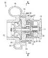
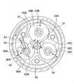
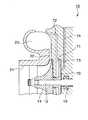
図1は第1実施形態の過給機を示す断面図、図2は図1のII−II線に沿う端面図、図3は増速機の変形例を示す端面図、図4はオイル循環経路を示す断面図、図5は第2実施形態の過給機を示す断面図、図6は図5のVI−VI線に沿う断面図、図7は軸受部を示す断面図、図8は第3実施形態の過給機を示す断面図、図9は第4実施形態の過給機を示す要部拡大断面図である。
【0024】
(第1実施形態)(図1〜図4)
図1の自動車用過給機10は、入力軸11の回転を増速機30により増速して出力軸12に伝えるものであり、入力軸11にはエンジン出力により駆動されるプーリ13が固定され、出力軸12にはインペラ14が設けられる。
【0025】
過給機10は、センタプレート15にコンプレッサハウジング16を固定してある。センタプレート15は軸受17により出力軸12を支持する。18はオイルシールである。コンプレッサハウジング16はインペラ14を収容し、吸込口21、過給通路22、スクロール23を備える。
【0026】
増速機30は、くさび作用を利用した摩擦ローラ式増速機であり、増速ハウジング31をセンタプレート15に固定して備え、増速ハウジング31は軸受32により入力軸11を支持する。33はオイルシールである。
【0027】
増速機30は、増速ハウジング31の内部で、出力軸12の端部に一体かつ同芯に設けた中心ローラ34を備える。
【0028】
増速機30は、増速ハウジング31の内部で、入力軸11の端部に円盤部35を介して一体かつ同芯に設けた外輪36を備える。このとき、外輪36は中心ローラ34に対し偏心して配置される。
【0029】
増速機30は、増速ハウジング31の内部で、中心ローラ34の外周面である被駆動側円筒面34Aと、外輪36の内周面である駆動側円筒面36Aとの間の、中心ローラ34の径方向に関する幅が上述の中心ローラ34と外輪36の偏心によって該中心ローラ34の周方向に関して不同となる環状空間37内に、3個の中間ローラ38A〜38Cを配置してある。このとき、センタプレート15と、該センタプレート15に連結ボルト41Aで固定化され(図4)、増速ハウジング31の内部で円盤部35に沿う位置に納められた連結板41に、3本の枢軸39A〜39Cの両端部を支持し、各枢軸39A〜39Cのそれぞれに中間ローラ38A〜38Cのそれぞれを回転自在に支持してある。各枢軸39A〜39Cは中心ローラ34、外輪36の中心軸と平行に配置される。各中間ローラ38A〜38Cは、それらの外周面を中心ローラ34の被駆動側円筒面34A、外輪36の駆動側円筒面36Aと転接する動力伝達用円筒面40A〜40Cとしている。
【0030】
3本の枢軸39A〜39Cのうち、2本の枢軸39B、39Cはそれらの両端部をセンタプレート15、連結板41に設けた支持孔に圧入又はガタなく挿入することにより固定される。これにより、枢軸39B、39Cは増速ハウジング31の内部で中心ローラ34の周方向及び半径方向に変位しない。
【0031】
他方、1本の枢軸39Aはその両端部をセンタプレート15、連結板41に設けた案内溝42の中で中心ローラ34の周方向及び半径方向に変位自在とし、中間ローラ38Aを可動ローラとしている。枢軸39Aはセンタプレート15又は連結板41に設けたバネ受43にバックアップされている押圧手段としてのバネ44により押圧され、中間ローラとしての可動ローラ38Aを前記環状空間37の幅が狭くなる方において中心ローラ34と外輪36に押付ける。
【0032】
従って、増速機30にあっては、センタプレート15に設けた取付ボス24を使用して過給機10をエンジンに取付け、入力用プーリ13にエンジンからの駆動力を入力すると、この駆動力が入力軸11から外輪36ヘ伝達される。このとき、外輪36と中心ローラ34は前述の如くに偏心していて前述の環状空間37が中心ローラ34の周方向に関して不同になっているため、外輪36がイの方向へ回転すると、可動ローラ38Aが外輪36と中心ローラ34との間でくさび作用を受けるロの方向に移動し、中心ローラ34の被駆動側円筒面34Aと外輪36の駆動側円筒面36Aと中間ローラ38A〜38Cの動力伝達用円筒面40A〜40Cの間に押付力ハを発生する。この押付力ハにより中心ローラ34の被駆動側円筒面34Aと外輪36の駆動側円筒面36Aと中間ローラ38A〜38Cの動力伝達用円筒面40A〜40Cの間に摩擦力を発生し、外輪36に伝えられた駆動力が中心ローラ34へ伝達され、中心ローラ34がニの方向へ回転する。中心ローラ34の回転は一体となった出力軸12の回転となり、出力軸に固定されたインペラ14が回転すると、吸込口21から空気を吸込み、この空気を過給してスクロール23に連通されたチャンバパイプからエンジンに供給する。
【0033】
ここで、中心ローラ34の周囲に3個の中間ローラ38A〜38Cがほぼ3等配されているので、中間ローラの1つである可動ローラ38Aで発生した押付力とほぼ同じ押付力が他の中間ローラとしてのガイドローラ38B、38Cでも発生し、3個の中間ローラ38A〜38Cで動力を伝達する。
【0034】
尚、エンジンの減速により、入力軸11から外輪36に伝えられる駆動力が回転方向イとは逆方向に変化した場合、可動ローラ38Aはロと反対方向に変位し、外輪36の駆動側円筒面36Aと可動ローラ38Aの動力伝達用円筒面40Aの接続が断たれ、外輪36と可動ローラ38Aとの間の動力伝達が断たれる。
【0035】
入力軸11から外輪36に入力される駆動力の向きにかかわらず動力の伝達を行なうためには、図3に示す如く、中間ローラ38Cも中間ローラ38Aと同様の可動ローラとし、可動ローラ38A、38Cをそれらに付帯のバネ44、44により環状空間37の幅の狭い部分に対し互いに向い合せてそれらの案内溝42の中で変位自在となるように押圧する構造にする。このとき、可動ローラ38A、38Cの枢軸39A、39Cには、くさび作用を発生する可動ローラ38A(又は38C)と反対側の可動ローラ38C(又は38A)がくさびから抜ける向きに逃げるのを防止するための不図示のストッパを付帯させる。
【0036】
入力軸11から出力軸12への最大伝達トルクを制限したい場合には、可動ローラ38Aがロの方向に変位可能な距離を案内溝42の長さによって規制する。これにより、外輪36がイの方向へ回転したときに、可動ローラ38Aが中心ローラ34との間で受けるくさび作用によって発生する押付力ハを制限できる。外輪36に入力される駆動力の向きにかかわらず動力の伝達を行なう図3の場合も同様に制限できる。これを利用して過給機10が供給可能な過給圧及び空気量を制限できる。
【0037】
以下、増速機30の潤滑、冷却構造について説明する。
増速機30の環状空間37にはトラクションオイルが封入され、中心ローラ34の被駆動側円筒面34A、外輪36の駆動側円筒面36A、中間ローラ38A〜38Cの動力伝達用円筒面40A〜40C、出力軸12の軸受17等の潤滑必要部を潤滑、冷却する。尚、トラクションオイルは、増速機30の内部又は外部に設けたオイルポンプにより、潤滑必要部に強制循環するものでも良い。
【0038】
増速機30にあっては、図4に示す如く、増速機30内の空間の外周部を、軸受17とオイルシール18に挟まれる空間45に連通する油路46をセンタプレート15に穿設し、増速機30の回転により跳ね上げられた増速ハウジング31の内壁付近たる外輪36の駆動側円筒面36Aまわりのトラクションオイルを油受け部36Bで受け、この油受け部36Bを通じて油路46から軸受17へ導き、それを中心ローラ34の被駆動側円筒面34Aへ流出させ、更に中間ローラ38A〜38Cの動力伝達用円筒面40A〜40Cへ案内し、トラクションオイルを中心ローラ34の被駆動側円筒面34A、外輪36の駆動側円筒面36A、中間ローラ38A〜38Cの動力伝達用円筒面40A〜40C、出力軸12の軸受17等の潤滑必要部に循環させることができる。
【0039】
尚、増速機30内にトラクションオイルが潤沢に存在するときは、回転の遠心力による圧力差によりトラクションオイルが循環することも期待できる。
【0040】
本実施形態によれば以下の作用がある。
▲1▼入力軸11の回転を増速してインペラ14が設けられている出力軸12に伝える増速機30として、くさび作用を利用した摩擦ローラ式増速機30を用いたから、外輪36、中間ローラ38A〜38C、中心ローラ34の互いの接触面間に伝達トルクに比例した押付力を得ることができ、高回転時の滑り、低回転時の駆動損失を生ずることがない。従って、低負荷、低回転時から高負荷、高回転時まで高い伝達効率を得ることができる。これにより、自動車用過給機10で問題となるエンジンの過給機駆動損失を低く抑えることができる。
【0041】
▲2▼従来の摩擦ローラ機構品と比べ、高い加工精度、選択勘合、焼きばめ等の専用組立行程が不要となり生産性が向上する。
【0042】
▲3▼歯車を用いない摩擦ローラ機構であるため、騒音、振動を小さくできる。
▲4▼高い伝達効率で駆動力の伝達が可能であるため、中間ローラ38A〜38C、中心ローラ34の軸方向長さを短縮することができる。このため、既存の摩擦ローラ機構や、遊星歯車機構を用いたものに比して過給機10の全長を短縮し、軽量、コンパクト化できる。
【0043】
▲5▼出力軸12の軸受17や外輪36、中間ローラ38A〜38C、中心ローラ34の互いの接触面の潤滑、冷却を行なうためのトラクションオイルの油路46、オイル溜まり部等の循環経路を過給機10の内部に設けたので、増速機30の回転による油の跳ね上げや遠心力による圧力差及び重力を利用し、トラクションオイルの循環性を向上させ、軸受17や接触面の潤滑状態を良好に保つことができる。
【0044】
(第2実施形態)(図5〜図7)
第2実施形態の過給機10が第1実施形態の過給機10と異なる点は、増速機30の内部のトラクションオイルを循環させるトロコイド式等のオイルポンプ50を増速機30に内蔵したことにある。
【0045】
オイルポンプ50は、図5、図6に示す如く、増速ハウジング31にアウタロータ51を組込み、入力軸11にインナロータ52をスプライン結合したものである。オイルポンプ50は増速ハウジング31に封入されたトラクションオイルを外部へ循環させて冷却し、再び増速ハウジング31の内部に導入し、中心ローラ34の被駆動側円筒面34A、外輪36の駆動側円筒面36A、中間ローラ38A〜38Cの動力伝達用円筒面40A〜40Cを潤滑、冷却することができる。
【0046】
また、オイルポンプ50が循環するトラクションオイルを送油管(不図示)を介してセンタプレート15に設けた油路53から油孔54を経て出力軸12の軸受17に供給し、このオイルを中心ローラ34の被駆動側円筒面34A、中間ローラ38A〜38Cの動力伝達用円筒面40A〜40Cに流出させることもできる。
【0047】
本実施形態によれば、出力軸12の軸受17や外輪36、中間ローラ38A〜38C、中心ローラ34の互いの接触面の潤滑、冷却を良好に行なうためのオイルポンプ50を過給機10の内部に備えたので、従来のように過給機10の外部にオイルポンプ50を配設する必要がなく、コンパクトにできる。
【0048】
(第3実施形態)(図8)
第3実施形態の過給機10が第1実施形態や第2実施形態の過給機10と異なる点は、入力軸11とプーリ13の間に電磁クラッチ60を設け、過給機10による過給の必要の有無に応じて電磁クラッチ60をオン/オフ制御可能としたことにある。電磁クラッチ60は、板式クラッチ、パウダークラッチ等を採用できる。
【0049】
本実施形態によれば、増速機30の内部の回転体の慣性力や駆動損失が小さいため、電磁クラッチ60も容量の小さいもので対応できる。このため、電磁クラッチ60を取付けた場合でもエンジンへの搭載が他の機械式過給機に比べて容易となる。
【0050】
(第4実施形態)(図9)
第4実施形態の過給機10が第1実施形態〜第3実施形態の過給機10と異なる点は、出力軸12にバランスプレート70を設けたことにある。バランスプレート70の一方側の空間71には、スクロール23から通路72を介して過給圧を導入する。バランスプレート70の他方側の空間73には、吸込口71から通路74を介して吸込圧(又は大気空間からの大気圧)を導入する。バランスプレート70に印加される両空間71、73の圧力がインペラ14に作用するスラスト荷重をバランスさせ、出力軸12の軸受17に作用するスラスト荷重を低減する。
【0051】
本実施形態によれば、出力軸12にバランスプレート70を設け、バランスプレート70の一方側に過給圧を印加し、バランスプレート70の他方側に吸込圧又は大気圧を印加するようにしたから、過給機10の出力軸12に作用するスラスト荷重の調整を行ない、出力軸12の軸受17にかかるスラスト荷重を低減し、耐久性を向上できる。
【0052】
以上、本発明の実施の形態を図面により詳述したが、本発明の具体的な構成はこの実施の形態に限られるものではなく、本発明の要旨を逸脱しない範囲の設計の変更等があっても本発明に含まれる。
【0053】
【発明の効果】
以上のように本発明によれば、高回転時の滑り、低回転時の駆動損失を生ずることがなく、騒音、振動も小さく、軽量、コンパクトな過給機を高い生産性で生産することができる。
【0054】
また、本発明によれば、出力軸の軸受部の潤滑、冷却性を向上するとともに、スラスト荷重を調整可能とし、耐久性を向上することができる。
【図面の簡単な説明】
【図1】図1は第1実施形態の過給機を示す断面図である。
【図2】図2は図1のII−II線に沿う端面図である。
【図3】図3は増速機の変形例を示す端面図である。
【図4】図4はオイル循環経路を示す断面図である。
【図5】図5は第2実施形態の過給機を示す断面図である。
【図6】図6は図5のVI−VI線に沿う断面図である。
【図7】図7は軸受部を示す断面図である。
【図8】図8は第3実施形態の過給機を示す断面図である。
【図9】図9は第4実施形態の過給機を示す要部拡大断面図である。
【符号の説明】
10 過給機
11 入力軸
12 出力軸
13 プーリ
14 インペラ
17 軸受
30 増速機
34 中心ローラ
34A 被駆動側円筒面
36 外輪
36A 駆動側円筒面
37 環状空間
38A 可動ローラ(中間ローラ)
38B、38C ガイドローラ(中間ローラ)
39A〜39C 枢軸
40A〜40C 動力伝達用円筒面
46 油路(循環経路)
50 オイルポンプ
60 電磁クラッチ
70 バランスプレート[0001]
BACKGROUND OF THE INVENTION
The present invention relates to a supercharger.
[0002]
[Prior art]
Conventionally, there is a turbocharger in which the rotation of an input shaft is accelerated by a speed increaser and transmitted to an output shaft, and an impeller is provided on the output shaft.
[0003]
In the prior art, in order to obtain a high speed increase ratio in the speed increaser, the speed increaser uses a planetary gear mechanism (Japanese Patent Laid-Open No. 4-203421) or uses a planetary friction roller mechanism (Special Table 11) -502596) has been proposed.
[0004]
[Problems to be solved by the invention]
In the case of using the planetary gear mechanism described in Japanese Patent Laid-Open No. 4-203421, there are problems of gear noise due to high-speed rotation and bearing life reduction due to vibration. In order to reduce the problem of noise and vibration, it is necessary to improve the processing accuracy and assembly accuracy of the gears, and productivity is poor.
[0005]
The one using the planetary friction roller mechanism described in JP-A-11-502596 has the following problems a to c because of the structure in which the planetary wheel and the friction roller such as the sun shaft are fastened by the flexible outer ring.
[0006]
a. When the rotation speed is high (impeller rotation speed: 75,000 rpm or more), the friction roller slips, and the driving force for supercharging cannot be transmitted to the impeller.
[0007]
b. In order to prevent slipping at high rotation, it is necessary to increase the force with which the outer ring tightens the friction roller. For this reason, an unnecessary tightening force is always applied to the friction roller at the time of low rotation, and the drive loss at the time of low rotation is large.
[0008]
c. In order to prevent slipping at high rotations and to secure an appropriate tightening force at low rotations, the outer ring and friction roller are dedicated to high processing accuracy, selective fitting, and appropriate shrink fitting of the outer ring. An assembly process is required and productivity is poor.
[0009]
SUMMARY OF THE INVENTION An object of the present invention is to produce a supercharger that is light and compact with low noise and vibration, without causing slippage at high rotation and drive loss at low rotation.
[0010]
Another object of the present invention is to improve the lubrication and cooling performance of the bearing portion of the output shaft, to adjust the thrust load, and to improve the durability.
[0011]
[Means for Solving the Problems]
According to a first aspect of the present invention, in the turbocharger in which the rotation of the input shaft is accelerated by the speed increaser and transmitted to the output shaft, and the impeller is provided on the output shaft, the speed increaser is coupled to the output shaft. A central roller, an outer ring arranged eccentrically with respect to the central roller, a driven side cylindrical surface that is an outer peripheral surface of the central roller, and a driving side cylindrical surface that is an inner peripheral surface of the outer ring. At least one or more rollers are arranged in an annular space in which the width in the radial direction is not the same in the circumferential direction of the central roller, and each of the intermediate rollers has a cylindrical surface for power transmission. The pivotshaft of the intermediate roller is movably arranged in the circumferential direction and the radial direction of the central roller, a balance plate is provided on the output shaft, a supercharging pressure is applied to one side of the balance plate, and the other side of the balance plate is applied. Suction pressure or atmospheric pressure It applied to is obtained ascomprising.
[0012]
According to a second aspect of the present invention, in the first aspect of the present invention, a circulation path is provided for circulating the traction oil inside the speed increaser to the lubrication required portion by the rotation of the speed increaser.
[0013]
According to a third aspect of the present invention, in the first or second aspect of the present invention, an oil pump for circulating the traction oil inside the speed increaser is incorporated in the speed increaser.
[0015]
The invention of claim4, further as in one of claims 1 to3, to be connected to the input pulley to said input shaft, is provided with a solenoid clutch between the input shaft and the input pulley.
[0016]
[Action]
According to the invention of claim 1, the following actions(a) to(e) are obtained.
(a) Since the friction roller type gearbox using the wedge action is used as a gearbox that accelerates the rotation of the input shaft and transmits it to the output shaft provided with the impeller, the outer ring, intermediate roller, center roller A pressing force proportional to the transmission torque can be obtained between the contact surfaces of each other, and slipping at high rotation and drive loss at low rotation do not occur. Therefore, a high transmission efficiency can be obtained from a low load and low rotation to a high load and high rotation. Thereby, the supercharger drive loss of the engine which becomes a problem in the supercharger for automobiles can be kept low.
[0017]
(b) Compared to conventional friction roller mechanism products, high assembly accuracy, selective fitting, shrink-fitting and other dedicated assembly processes are not required, and productivity is improved.
[0018]
(c) Since the friction roller mechanism does not use gears, noise and vibration can be reduced.
(d) Since the driving force can be transmitted with high transmission efficiency, the axial lengths of the intermediate roller and the central roller can be shortened. For this reason, compared with the thing using the existing friction roller mechanism and the planetary gear mechanism, the full length of a supercharger can be shortened, and it can be made lightweight and compact.
(e) Since abalance plate is provided on the output shaft, supercharging pressure is applied to one side of the balance plate, and suction pressure or atmospheric pressure is applied to the other side of the balance plate. It is possible to adjust the thrust load that acts, reduce the thrust load applied to the bearing portion of the output shaft, and improve the durability.
[0019]
The invention according to claim 2 has the following effect(f) .
(f) Circulation paths such as traction oil passages and oil reservoirs are provided inside the turbocharger to lubricate and cool the contact surfaces of the output shaft bearings, outer ring, intermediate roller, and center roller. Therefore, it is possible to improve the circulation performance of the traction oil by using the oil splash due to the rotation of the speed increaser and the pressure difference and gravity due to the centrifugal force, and to keep the lubrication state of the bearing portion and the contact surface in good condition.
[0020]
The invention according to claim 3 has the following effect(g) .
(g) The supercharger is equipped with an oil pump for good lubrication and cooling of the contact surfaces of the output shaft bearing, outer ring, intermediate roller, and center roller. There is no need to install an oil pump outside the machine, and it can be made compact.
[0022]
The invention according to claim4 has the following action(h) .
(h) Since the inertial force and driving loss of the rotating body inside the gearbox are small, the electromagnetic clutch can be handled with a small capacity. For this reason, even when an electromagnetic clutch is attached, mounting on the engine is easier than other mechanical superchargers.
[0023]
DETAILED DESCRIPTION OF THE INVENTION
1 is a cross-sectional view showing the turbocharger of the first embodiment, FIG. 2 is an end view taken along the line II-II in FIG. 1, FIG. 3 is an end view showing a modification of the speed increaser, and FIG. FIG. 5 is a sectional view showing the turbocharger of the second embodiment, FIG. 6 is a sectional view taken along the line VI-VI in FIG. 5, FIG. 7 is a sectional view showing the bearing portion, and FIG. Sectional drawing which shows the supercharger of 3rd Embodiment, FIG. 9 is a principal part expanded sectional view which shows the supercharger of 4th Embodiment.
[0024]
First Embodiment (FIGS. 1 to 4)
The
[0025]
The
[0026]
The
[0027]
The
[0028]
The
[0029]
The
[0030]
Of the three
[0031]
On the other hand, one
[0032]
Therefore, in the
[0033]
Here, since the three
[0034]
When the driving force transmitted from the
[0035]
In order to transmit power regardless of the direction of the driving force input from the
[0036]
When it is desired to limit the maximum transmission torque from the
[0037]
Hereinafter, the lubrication and cooling structure of the
Traction oil is enclosed in the
[0038]
In the
[0039]
In addition, when traction oil exists abundantly in the
[0040]
According to this embodiment, there are the following operations.
(1) Since the friction roller type
[0041]
(2) Compared with the conventional friction roller mechanism product, a dedicated assembly process such as high machining accuracy, selective fitting, shrink fitting and the like is unnecessary, and productivity is improved.
[0042]
(3) Since the friction roller mechanism does not use gears, noise and vibration can be reduced.
(4) Since the driving force can be transmitted with high transmission efficiency, the axial lengths of the
[0043]
(5) A circulation path such as a
[0044]
Second Embodiment (FIGS. 5 to 7)
The
[0045]
As shown in FIGS. 5 and 6, the
[0046]
Further, traction oil circulated by the
[0047]
According to the present embodiment, the
[0048]
(Third Embodiment) (FIG. 8)
The
[0049]
According to the present embodiment, since the inertial force and driving loss of the rotating body inside the
[0050]
(Fourth Embodiment) (FIG. 9)
The
[0051]
According to the present embodiment, the
[0052]
Although the embodiment of the present invention has been described in detail with reference to the drawings, the specific configuration of the present invention is not limited to this embodiment, and there are design changes and the like without departing from the gist of the present invention. Is included in the present invention.
[0053]
【The invention's effect】
As described above, according to the present invention, it is possible to produce a lightweight, compact supercharger with high productivity without causing slippage at high rotation and drive loss at low rotation, with low noise and vibration. it can.
[0054]
Further, according to the present invention, the lubrication and cooling performance of the bearing portion of the output shaft can be improved, the thrust load can be adjusted, and the durability can be improved.
[Brief description of the drawings]
FIG. 1 is a cross-sectional view showing a supercharger according to a first embodiment.
FIG. 2 is an end view taken along the line II-II in FIG.
FIG. 3 is an end view showing a modification of the speed increaser.
FIG. 4 is a cross-sectional view showing an oil circulation path.
FIG. 5 is a cross-sectional view showing a supercharger according to a second embodiment.
6 is a cross-sectional view taken along line VI-VI in FIG.
FIG. 7 is a cross-sectional view showing a bearing portion.
FIG. 8 is a cross-sectional view showing a supercharger according to a third embodiment.
FIG. 9 is an enlarged sectional view of an essential part showing a supercharger according to a fourth embodiment.
[Explanation of symbols]
DESCRIPTION OF
38B, 38C Guide roller (intermediate roller)
39A-
50
Claims (4)
Translated fromJapanese前記増速機が、
出力軸に結合される中心ローラと、
中心ローラに対し偏心して配置される外輪と、
中心ローラの外周面である被駆動側円筒面と、外輪の内周面である駆動側円筒面との間の、中心ローラの径方向に関する幅が該中心ローラの周方向に関して不同となる環状空間内に配置され、それぞれの外周面を動力伝達用円筒面とした複数の中間ローラとを有して構成され、
少なくとも1個以上の中間ローラの枢軸が中心ローラの周方向及び半径方向に可動配置されてなるとともに、
前記出力軸にバランスプレートを設け、バランスプレートの一方側に過給圧を印加し、バランスプレートの他方側に吸込圧又は大気圧を印加してなることを特徴とする過給機。In the turbocharger in which the rotation of the input shaft is accelerated by the gearbox and transmitted to the output shaft, and the impeller is provided on the output shaft.
The gearbox is
A central roller coupled to the output shaft;
An outer ring arranged eccentric with respect to the central roller;
An annular space between the driven cylindrical surface that is the outer peripheral surface of the central roller and the driving cylindrical surface that is the inner peripheral surface of the outer ring, in which the width in the radial direction of the central roller is not the same in the circumferential direction of the central roller And a plurality of intermediate rollers each having an outer circumferential surface as a cylindrical surface for power transmission,
The pivot shaft of at least one intermediate roller is movably arranged in the circumferential direction and the radial direction of the central roller, and
A turbocharger comprising a balance plate on the output shaft, a supercharging pressure applied to one side of the balance plate, and a suction pressure or atmospheric pressure applied to the other side of the balance plate .
Priority Applications (6)
| Application Number | Priority Date | Filing Date | Title |
|---|---|---|---|
| JP2001398353AJP3928035B2 (en) | 2001-12-27 | 2001-12-27 | Turbocharger |
| US10/320,131US6796126B2 (en) | 2001-12-27 | 2002-12-16 | Supercharger |
| CA002414744ACA2414744A1 (en) | 2001-12-27 | 2002-12-19 | Supercharger |
| EP02028489AEP1323909A3 (en) | 2001-12-27 | 2002-12-19 | Supercharger |
| TW091136883ATWI226415B (en) | 2001-12-27 | 2002-12-20 | Supercharger |
| CN02159619ACN1432721A (en) | 2001-12-27 | 2002-12-25 | Booster |
Applications Claiming Priority (1)
| Application Number | Priority Date | Filing Date | Title |
|---|---|---|---|
| JP2001398353AJP3928035B2 (en) | 2001-12-27 | 2001-12-27 | Turbocharger |
Publications (2)
| Publication Number | Publication Date |
|---|---|
| JP2003201850A JP2003201850A (en) | 2003-07-18 |
| JP3928035B2true JP3928035B2 (en) | 2007-06-13 |
Family
ID=19189338
Family Applications (1)
| Application Number | Title | Priority Date | Filing Date |
|---|---|---|---|
| JP2001398353AExpired - LifetimeJP3928035B2 (en) | 2001-12-27 | 2001-12-27 | Turbocharger |
Country Status (6)
| Country | Link |
|---|---|
| US (1) | US6796126B2 (en) |
| EP (1) | EP1323909A3 (en) |
| JP (1) | JP3928035B2 (en) |
| CN (1) | CN1432721A (en) |
| CA (1) | CA2414744A1 (en) |
| TW (1) | TWI226415B (en) |
Families Citing this family (27)
| Publication number | Priority date | Publication date | Assignee | Title |
|---|---|---|---|---|
| US6994531B2 (en)* | 2002-04-23 | 2006-02-07 | Nsk Ltd. | High-speed fluidic device |
| US7128061B2 (en)* | 2003-10-31 | 2006-10-31 | Vortech Engineering, Inc. | Supercharger |
| US7055507B2 (en)* | 2004-03-29 | 2006-06-06 | Borgwarner Inc. | Continuously variable drive for superchargers |
| JP2006002633A (en) | 2004-06-16 | 2006-01-05 | Yamaha Marine Co Ltd | Water jet propulsion boat |
| JP2006037730A (en) | 2004-07-22 | 2006-02-09 | Yamaha Marine Co Ltd | Intake device for supercharged engine |
| JP2006077699A (en)* | 2004-09-10 | 2006-03-23 | Yamaha Marine Co Ltd | Lubricating structure for supercharging device |
| JP2006083713A (en)* | 2004-09-14 | 2006-03-30 | Yamaha Marine Co Ltd | Lubricating structure of supercharger |
| US20060180130A1 (en)* | 2005-02-14 | 2006-08-17 | St James David | Motor assisted mechanical supercharging system |
| JP2007062432A (en) | 2005-08-29 | 2007-03-15 | Yamaha Marine Co Ltd | Small planing boat |
| JP4614853B2 (en) | 2005-09-26 | 2011-01-19 | ヤマハ発動機株式会社 | Turbocharger mounting structure |
| JP4668143B2 (en)* | 2006-07-31 | 2011-04-13 | 株式会社エッチ・ケー・エス | Gearbox and reducer |
| DE102007056391B4 (en)* | 2007-10-23 | 2011-02-03 | Keiper Gmbh & Co. Kg | gear stage |
| US9086012B2 (en)* | 2010-08-13 | 2015-07-21 | Eaton Corporation | Supercharger coupling |
| JP5665602B2 (en)* | 2011-02-25 | 2015-02-04 | 三菱重工業株式会社 | Multistage turbocharger structure |
| US8866687B2 (en) | 2011-11-16 | 2014-10-21 | Andrew Llc | Modular feed network |
| US8558746B2 (en) | 2011-11-16 | 2013-10-15 | Andrew Llc | Flat panel array antenna |
| US9160049B2 (en) | 2011-11-16 | 2015-10-13 | Commscope Technologies Llc | Antenna adapter |
| WO2014010652A1 (en) | 2012-07-11 | 2014-01-16 | 川崎重工業株式会社 | Supercharger mounting structure for engine |
| CN102817710B (en)* | 2012-09-04 | 2016-03-02 | 杭州闪鹿科技有限公司 | centrifugal mechanical supercharger |
| JP6225762B2 (en)* | 2014-03-12 | 2017-11-08 | 株式会社豊田自動織機 | Turbo compressor |
| US10808701B2 (en)* | 2016-02-04 | 2020-10-20 | Eaton Corporation | Cartridge style front cover and coupling cavity sleeve for automotive supercharger |
| DE102017106525A1 (en)* | 2016-03-28 | 2017-09-28 | Kabushiki Kaisha Toyota Jidoshokki | Speed increaser and centrifugal compressor |
| JP6740950B2 (en)* | 2017-03-31 | 2020-08-19 | 株式会社豊田自動織機 | Centrifugal compressor |
| CA3089155A1 (en) | 2018-06-06 | 2019-12-12 | Vectis Drive Inc. | Fixed ratio traction or friction drive |
| CN110630711A (en)* | 2019-09-03 | 2019-12-31 | 广东广顺新能源动力科技有限公司 | A multifunctional high speed air compressor |
| JP2021110386A (en)* | 2020-01-09 | 2021-08-02 | 三菱重工コンプレッサ株式会社 | Transmission and compressor system |
| CN111594461B (en)* | 2020-05-26 | 2024-11-15 | 烟台东德实业有限公司 | A heat exchange speed increasing air pump |
Family Cites Families (19)
| Publication number | Priority date | Publication date | Assignee | Title |
|---|---|---|---|---|
| US2344078A (en) | 1939-05-23 | 1944-03-14 | Brissonnet Pierre | Transmission |
| US3945270A (en)* | 1975-02-18 | 1976-03-23 | Wedgtrac Corporation | Friction drive transmission |
| US4249750A (en)* | 1979-02-22 | 1981-02-10 | Kantner Harold H | Fluid-power converter with paired rotators providing seals and displacement paths and pump-motor utilizing same |
| US4408503A (en)* | 1981-03-06 | 1983-10-11 | Excelermatic Inc. | Traction roller transmission |
| FR2563063B1 (en)* | 1984-04-12 | 1986-06-20 | Bech Jean | EPICYCLOIDAL INDUCTION COUPLER FOR REDUCED ROTATION SPEED MACHINES |
| EP0377643B1 (en)* | 1987-09-05 | 1991-10-23 | ZF FRIEDRICHSHAFEN Aktiengesellschaft | Mechanical drive for the charging blower of internal combustion engines |
| JP3060489B2 (en)* | 1990-06-15 | 2000-07-10 | アイシン精機株式会社 | Machine driven centrifugal turbocharger |
| JPH04203421A (en) | 1990-11-30 | 1992-07-24 | Tochigi Fuji Ind Co Ltd | Centrifugal supercharger |
| JP3281100B2 (en)* | 1993-03-29 | 2002-05-13 | 栃木富士産業株式会社 | Supercharger |
| DK171047B1 (en) | 1995-03-29 | 1996-04-29 | Anders Peter Kolstrup | Planetary gears for high rpm |
| US5716081A (en) | 1996-03-11 | 1998-02-10 | Automotive Products (Usa), Inc. | Spring clip for quick connect coupling |
| JPH10316081A (en) | 1997-01-29 | 1998-12-02 | Nippon Seiko Kk | Bicycle driving force assist device |
| JPH11294548A (en) | 1998-04-08 | 1999-10-29 | Ntn Corp | Supercharger and multi-stage roller accelerator used therefor |
| US6231302B1 (en)* | 1999-06-08 | 2001-05-15 | G. Fonda Bonardi | Thermal control system for gas-bearing turbocompressors |
| IT1308779B1 (en) | 1999-07-02 | 2002-01-10 | Elasis Sistema Ricerca Fiat | DEVICE FOR ADJUSTING THE DELIVERY PRESSURE OF A PUMP, SUITABLE FOR FUEL SUPPLY TO A COMBUSTION ENGINE |
| JP2001059469A (en) | 1999-08-18 | 2001-03-06 | Honda Motor Co Ltd | Starter device for starting the engine |
| JP4513158B2 (en) | 2000-03-28 | 2010-07-28 | 日本精工株式会社 | Friction roller type transmission |
| JP2002221263A (en) | 2000-11-27 | 2002-08-09 | Nsk Ltd | Wind power generator |
| JP4215508B2 (en) | 2001-02-14 | 2009-01-28 | ローランズ・ロトレックス・エイ/エス | Planetary wheel and its use |
- 2001
- 2001-12-27JPJP2001398353Apatent/JP3928035B2/ennot_activeExpired - Lifetime
- 2002
- 2002-12-16USUS10/320,131patent/US6796126B2/ennot_activeExpired - Lifetime
- 2002-12-19EPEP02028489Apatent/EP1323909A3/ennot_activeWithdrawn
- 2002-12-19CACA002414744Apatent/CA2414744A1/ennot_activeAbandoned
- 2002-12-20TWTW091136883Apatent/TWI226415B/enactive
- 2002-12-25CNCN02159619Apatent/CN1432721A/enactivePending
Also Published As
| Publication number | Publication date |
|---|---|
| CA2414744A1 (en) | 2003-06-27 |
| TW200301337A (en) | 2003-07-01 |
| US6796126B2 (en) | 2004-09-28 |
| EP1323909A3 (en) | 2009-05-27 |
| JP2003201850A (en) | 2003-07-18 |
| CN1432721A (en) | 2003-07-30 |
| TWI226415B (en) | 2005-01-11 |
| US20030121507A1 (en) | 2003-07-03 |
| EP1323909A2 (en) | 2003-07-02 |
Similar Documents
| Publication | Publication Date | Title |
|---|---|---|
| JP3928035B2 (en) | Turbocharger | |
| US6994531B2 (en) | High-speed fluidic device | |
| US4950213A (en) | Planetary gear transmission having an arrangement for efficient lubrication of planetary gears | |
| US4955852A (en) | Planetary gear mechanism having means for accurate alignment of sun gear | |
| US20050196295A1 (en) | Centrifugal air compressor | |
| JP3878796B2 (en) | Bearing structure | |
| CA2059756A1 (en) | Two-speed planetary friction accessory drive | |
| WO2004033911A1 (en) | Integrated speed reducer and pump assembly | |
| JP3748680B2 (en) | Lubricating structure of continuously variable transmission | |
| JP2004092414A (en) | High-speed fluid device | |
| US11624363B2 (en) | Dual drive gerotor pump | |
| JP2004308757A (en) | Friction roller type transmission and high speed fluid device | |
| USRE26978E (en) | Accessory drive mechanism | |
| JP2003314446A (en) | High-speed fluid device | |
| JP2004116415A (en) | High-speed fluid device | |
| JP2004132460A (en) | Drive device and high-speed fluid device | |
| JP2004156531A (en) | Friction roller type transmission integrated compressor | |
| JP2004308756A (en) | Friction roller type transmission | |
| JP2002039305A (en) | Friction roller type transmission | |
| JP2006307773A (en) | Speed increaser | |
| JP2900285B2 (en) | Supercharger with planetary speed-up mechanism | |
| JP2004239407A (en) | Friction roller type transmission and high speed fluid device | |
| JP2003343435A (en) | High-speed fluid device | |
| JP2004169858A (en) | Friction roller type transmission with built-in oil pump | |
| JP2004156743A (en) | Drive device and high-speed fluid device |
Legal Events
| Date | Code | Title | Description |
|---|---|---|---|
| A621 | Written request for application examination | Free format text:JAPANESE INTERMEDIATE CODE: A621 Effective date:20041214 | |
| A131 | Notification of reasons for refusal | Free format text:JAPANESE INTERMEDIATE CODE: A131 Effective date:20061030 | |
| A977 | Report on retrieval | Free format text:JAPANESE INTERMEDIATE CODE: A971007 Effective date:20061101 | |
| A521 | Request for written amendment filed | Free format text:JAPANESE INTERMEDIATE CODE: A523 Effective date:20061213 | |
| TRDD | Decision of grant or rejection written | ||
| A01 | Written decision to grant a patent or to grant a registration (utility model) | Free format text:JAPANESE INTERMEDIATE CODE: A01 Effective date:20070130 | |
| A711 | Notification of change in applicant | Free format text:JAPANESE INTERMEDIATE CODE: A711 Effective date:20070208 | |
| A61 | First payment of annual fees (during grant procedure) | Free format text:JAPANESE INTERMEDIATE CODE: A61 Effective date:20070208 | |
| A521 | Request for written amendment filed | Free format text:JAPANESE INTERMEDIATE CODE: A821 Effective date:20070209 | |
| R150 | Certificate of patent or registration of utility model | Ref document number:3928035 Country of ref document:JP Free format text:JAPANESE INTERMEDIATE CODE: R150 Free format text:JAPANESE INTERMEDIATE CODE: R150 | |
| FPAY | Renewal fee payment (event date is renewal date of database) | Free format text:PAYMENT UNTIL: 20110316 Year of fee payment:4 | |
| R250 | Receipt of annual fees | Free format text:JAPANESE INTERMEDIATE CODE: R250 | |
| FPAY | Renewal fee payment (event date is renewal date of database) | Free format text:PAYMENT UNTIL: 20110316 Year of fee payment:4 | |
| FPAY | Renewal fee payment (event date is renewal date of database) | Free format text:PAYMENT UNTIL: 20120316 Year of fee payment:5 | |
| R250 | Receipt of annual fees | Free format text:JAPANESE INTERMEDIATE CODE: R250 | |
| FPAY | Renewal fee payment (event date is renewal date of database) | Free format text:PAYMENT UNTIL: 20120316 Year of fee payment:5 | |
| FPAY | Renewal fee payment (event date is renewal date of database) | Free format text:PAYMENT UNTIL: 20130316 Year of fee payment:6 | |
| R250 | Receipt of annual fees | Free format text:JAPANESE INTERMEDIATE CODE: R250 | |
| FPAY | Renewal fee payment (event date is renewal date of database) | Free format text:PAYMENT UNTIL: 20130316 Year of fee payment:6 | |
| FPAY | Renewal fee payment (event date is renewal date of database) | Free format text:PAYMENT UNTIL: 20140316 Year of fee payment:7 | |
| R250 | Receipt of annual fees | Free format text:JAPANESE INTERMEDIATE CODE: R250 | |
| R250 | Receipt of annual fees | Free format text:JAPANESE INTERMEDIATE CODE: R250 | |
| R250 | Receipt of annual fees | Free format text:JAPANESE INTERMEDIATE CODE: R250 | |
| R250 | Receipt of annual fees | Free format text:JAPANESE INTERMEDIATE CODE: R250 | |
| R250 | Receipt of annual fees | Free format text:JAPANESE INTERMEDIATE CODE: R250 | |
| R250 | Receipt of annual fees | Free format text:JAPANESE INTERMEDIATE CODE: R250 | |
| R250 | Receipt of annual fees | Free format text:JAPANESE INTERMEDIATE CODE: R250 | |
| R250 | Receipt of annual fees | Free format text:JAPANESE INTERMEDIATE CODE: R250 | |
| R250 | Receipt of annual fees | Free format text:JAPANESE INTERMEDIATE CODE: R250 | |
| EXPY | Cancellation because of completion of term |