JP3925906B2 - Mobile map display device - Google Patents
Mobile map display deviceDownload PDFInfo
- Publication number
- JP3925906B2 JP3925906B2JP2002008085AJP2002008085AJP3925906B2JP 3925906 B2JP3925906 B2JP 3925906B2JP 2002008085 AJP2002008085 AJP 2002008085AJP 2002008085 AJP2002008085 AJP 2002008085AJP 3925906 B2JP3925906 B2JP 3925906B2
- Authority
- JP
- Japan
- Prior art keywords
- scroll
- scroll cursor
- current position
- map
- map image
- Prior art date
- Legal status (The legal status is an assumption and is not a legal conclusion. Google has not performed a legal analysis and makes no representation as to the accuracy of the status listed.)
- Expired - Lifetime
Links
- 238000004364calculation methodMethods0.000claimsdescription11
- 238000000034methodMethods0.000description17
- 230000006870functionEffects0.000description11
- 238000010586diagramMethods0.000description9
- 238000004891communicationMethods0.000description7
- 238000013500data storageMethods0.000description3
- 239000004973liquid crystal related substanceSubstances0.000description2
- 230000004048modificationEffects0.000description2
- 238000012986modificationMethods0.000description2
- 238000003825pressingMethods0.000description2
- 230000002194synthesizing effectEffects0.000description2
- 230000001413cellular effectEffects0.000description1
- 230000000694effectsEffects0.000description1
- 239000011159matrix materialSubstances0.000description1
Images


Landscapes
- Controls And Circuits For Display Device (AREA)
- Traffic Control Systems (AREA)
- Instructional Devices (AREA)
- Navigation (AREA)
Description
Translated fromJapanese【0001】
【発明の属する技術分野】
本発明は携帯地図表示装置に係り、とくに地図画像のスクロールが可能な携帯地図表示装置に関する。
【0002】
【従来の技術】
歩行者が携帯しながら現在位置を地図上で確認できるようにした携帯地図表示装置が有る。この携帯地図表示装置は、小型のGPS受信機により現在位置を検出し、ICメモリカードに記憶した地図データまたは通信によりネットワーク経由で外部の地図データ配信コンピュータシステムから入手した地図データを用いて、現在位置周辺の一定範囲の地図画像を現在位置マークとともに描画し、液晶ディスプレイに表示させるようになっている。
【0003】
ユーザが図11に示す道路地図上で見て点Pに居る場合、画面には例えば図12(1)の如く、現在位置マークMMを中心とした一定範囲(図11の枠線Aの範囲)の北を上向きにした地図画像MIが表示されるので、ユーザは現在位置がどこであり、周りに何があるか地図上で確認することができる。
【0004】
携帯地図表示装置にも車載用地図表示装置と同様に地図スクロール機能が有るので、画面に表示された地図画像の範囲より外側の地図を見たい場合、地図スクロール操作をすれば良い。
但し、車載用地図表示装置では地図の描画速度が十分速いのでスクロール操作に従い、地図画像を連続的にスクロールさせることができるが、携帯用地図表示装置では一般に地図描画速度が遅いため、地図画像を連続的にスクロールさせることはせず、飛び飛びに描画エリアを変えるようにしている。
【0005】
具体的には、図12(1)の表示状態で、図11の斜線Qの範囲の地図を見たい場合、まず、左スクロールキーを1回押す。すると、図11の枠線Aを、該枠線Aの東西方向の幅の4/5程度だけ西にずらした枠線Bの範囲の地図画像を描画して表示させる(図12(2)参照)。次に、下スクロールキーを1回押す。すると、図11の枠線Bを、該枠線Bの南北方向の幅の4/5程度だけ南にずらした枠線Cの範囲の地図画像を描画して表示させる(図12(3)参照)。更に、右スクロールキーを1回押す。すると、図11の枠線Cを、該枠線Bの東西方向の幅の4/5程度だけ東にずらした枠線Dの範囲の地図画像を描画して表示させる(図12(4)参照)。これにより、ユーザ所望の範囲Qの地図を見ることができる。
【0006】
【発明が解決しようとする課題】
しかしながら、上記した従来の携帯地図表示装置では、地図スクロールが東西方向または南北方向に飛び飛びになされるため、所望の範囲が図11のQであったとき、所望の範囲を一度に全部見ることができず、地図スクロール操作により、所望の範囲を一部分ずつしか見れないので(図12のq1〜q4参照)、所望の範囲の地理的状況がどのようになっているのか判りずらいという問題があった。
本発明は上記した従来技術の問題に鑑み、所望の範囲の地図を一目で見られる携帯地図表示装置を提供することを、その目的とする。
【0007】
【課題を解決するための手段】
請求項1記載の発明では、現在位置を検出する現在位置検出手段と、地図画像を現在位置マーク、スクロールカーソルとともに表示可能な表示手段と、スクロールカーソルの移動操作をするスクロール操作手段と、スクロールカーソル移動操作が開始されると、その時点の現在位置を初期値にしてスクロールカーソル移動操作に従い可変するスクロールカーソル位置座標を計算して表示画面上のスクロールカーソル位置を検出するスクロールカーソル位置座標計算手段と、スクロールカーソル移動操作が開始される前は、地図データを用いて現在位置周辺の一定範囲の地図画像を、該地図画像の該当する箇所に重ねた現在位置マークとともに表示手段に表示させ、スクロールカーソル移動操作が開始されると、スクロールカーソル位置が画面の地図画像の端に来るまでは、スクロールカーソル移動操作開始時点で表示された地図画像の該当する箇所にスクロールカーソルを重ねて表示手段に表示させ、スクロールカーソル位置が画面の地図画像の端に来ると、その時点のスクロールカーソル位置を中心とした周辺の一定範囲の地図画像を、スクロールカーソルを画面中心にして描画し直し、該地図画像の該当する箇所に重ねた現在位置マーク、スクロールカーソルとともに表示手段に表示させる地図表示制御手段と、を備えたことを特徴としている。
請求項3記載の発明では、現在位置を検出する現在位置検出手段と、地図画像を現在位置マーク、スクロールカーソルとともに表示可能な表示手段と、スクロールカーソルの移動操作をするスクロール操作手段と、スクロールカーソル移動操作が開始されると、その時点の現在位置を初期値にしてスクロールカーソル移動操作に従いスクロールカーソル位置座標を計算して表示画面上のスクロールカーソル位置を検出するスクロールカーソル位置座標計算手段と、スクロールカーソル移動操作が開始される前は、地図データを用いて現在位置周辺の一定範囲の地図画像を、該地図画像の該当する箇所に重ねた現在位置マークとともに表示手段に表示させ、スクロールカーソル移動操作が開始されると、スクロールカーソル位置が画面の地図画像の端に来るまでは、スクロールカーソル移動操作開始時点の地図画像の該当する箇所にスクロールカーソル、スクロールカーソル移動操作開始時点の現在位置とスクロールカーソル位置を結ぶ直線を重ねて表示手段に表示させ、スクロールカーソル位置が画面の地図画像の端に来ると、その時点のスクロールカーソル位置を中心とした周辺の一定範囲の地図画像を、スクロールカーソルを画面中心にして描画し直し、該地図画像の該当する箇所に重ねた現在位置マーク、スクロールカーソル、スクロールカーソル位置からスクロールカーソル移動操作開始時点の現在位置に向けた直線とともに表示手段に表示させる地図表示制御手段と、を備えたことを特徴としている。
請求項5記載の発明では、現在位置を検出する現在位置検出手段と、地図画像を現在位置マーク、スクロールカーソルとともに表示可能な表示手段と、スクロールカーソルの移動操作をするスクロール操作手段と、スクロールカーソル移動操作が開始されると、その時点の現在位置を初期値にしてスクロールカーソル移動操作に従いスクロールカーソル位置座標を計算して表示画面上のスクロールカーソル位置を検出するスクロールカーソル位置座標計算手段と、スクロールカーソル移動操作が開始される前は、地図データを用いて現在位置周辺の一定範囲の地図画像を、該地図画像の該当する箇所に重ねた現在位置マークとともに表示手段に表示させ、スクロールカーソル移動操作が開始されると、スクロールカーソル位置が画面の地図画像の端に来るまでは、現在位置周辺の一定範囲の地図画像の該当する箇所に現在位置マーク、スクロールカーソルを重ねた画像を表示手段に表示させ、スクロールカーソル位置が画面の地図画像の端に来ると、その時点のスクロールカーソル位置を中心とした周辺の一定範囲の地図画像を、スクロールカーソルを画面中心にして描画し直し、該地図画像の該当する箇所に重ねた現在位置マーク、スクロールカーソルとともに表示手段に表示させる地図表示制御手段と、を備えたことを特徴としている。
請求項7記載の発明では、現在位置を検出する現在位置検出手段と、地図画像を現在位置マーク、スクロールカーソルとともに表示可能な表示手段と、スクロールカーソルの移動操作をするスクロール操作手段と、スクロールカーソル移動操作が開始されると、その時点の現在位置を初期値にしてスクロールカーソル移動操作に従いスクロールカーソル位置座標を計算して表示画面上のスクロールカーソル位置を検出するスクロールカーソル位置座標計算手段と、スクロールカーソル移動操作が開始される前は、地図データを用いて現在位置周辺の一定範囲の地図画像を、該地図画像の該当する箇所に重ねた現在位置マークとともに表示手段に表示させ、スクロールカーソル移動操作が開始されると、スクロールカーソル位置が画面の地図画像の端に来るまでは、現在位置周辺の一定範囲の地図画像の該当する箇所に現在位置マーク、スクロールカーソル、現在位置とスクロールカーソルを結ぶ直線を重ねた画像を表示手段に表示させ、スクロールカーソル位置が画面の地図画像の端に来ると、その時点のスクロールカーソル位置を中心とした周辺の一定範囲の地図画像を、スクロールカーソルを画面中心にして描画し直し、該地図画像の該当する箇所に重ねた現在位置マーク、スクロールカーソル、スクロールカーソル位置から現在位置に向けた直線とともに表示手段に表示させる地図表示制御手段と、を備えたことを特徴としている。
請求項2、4では、スクロールカーソル移動操作開始時点での現在位置とスクロールカーソル位置間の地理的距離を計算する距離計算手段を設け、地図表示制御手段は、スクロールカーソル移動操作が開始されたあと、地図画像に距離計算手段で計算された距離を重ねて表示手段に表示させるようにしたこと、を特徴としている。
請求項6、8では、現在位置とスクロールカーソル位置間の地理的距離を計算する距離計算手段を設け、地図表示制御手段は、スクロールカーソル移動操作が開始されたあと、地図画像に距離計算手段で計算された距離を重ねて表示手段に表示させるようにしたこと、を特徴としている。
【0008】
【発明の実施の形態】
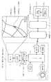
次に、本発明の一つの実施の形態を図1を参照して説明する。図1は本発明に係る地図表示機能付携帯電話端末の内、とくに地図表示機能に関係する部分の構成を示すブロック図である。
1は携帯地図表示装置の一例としての地図表示機能付携帯電話端末、20は地図表示機能付携帯電話端末とデータ通信可能な移動網、30は移動網と接続されたインターネット、40はインターネットと接続されたコンテンツ配信事業者の運営する情報配信装置(情報配信コンピュータシステム)であり、エリア別に分割された地図描画用の地図データを蓄積した地図データ蓄積部41と、外部からエリアを指定して地図データの要求が有ると、地図データ蓄積部41から該当するエリアの地図データを読み出し、要求元に返信する情報配信部42を含む。
【0009】
地図表示機能付携帯電話端末1の内、2は現在位置を衛星航法で検出するGPS受信部、3は地図スクロール操作(スクロールカーソル移動操作)等を行う操作部であり、上スクロールキー3a、下スクロールキー3b、左スクロールキー3c、右スクロールキー3d、クリアキー(図示せず)を含む。4は地図画像を現在位置マーク、スクロールカーソルとともに表示する液晶ドットマトリクス式の表示部、5は地図データを記憶可能な記憶部、6は画像メモリ部であり、各々1画面分の画像記憶領域を有する第1記憶領域6a及び第2記憶領域6bを有する。7は合成部であり、画像メモリ部6の第1記憶領域6aに記憶された画像の上に第2記憶領域6bに記憶された画像を合成しながら所定の映像信号に変換して表示部4へ出力し、画像を画面表示させる。8は地図データ要求信号を無線回線を介して移動網20の側に送信したり、移動網20の側から無線回線を介して返信された地図データを受信して出力したりする通信部、9はマイコン構成のコントロール部であり、地図表示制御処理を行う(コントロール部9は通話制御処理も行うがここでは説明を省略する)。
【0010】
コントロール部9はGPS受信部2で検出された現在位置周辺(現在位置を含むエリアと、当該エリアを取り囲むエリア)の地図データが全て記憶部5に揃っている状態でないとき、通信部8を制御して、情報配信装置40宛に不足分のエリア情報を含む地図データ要求信号を無線回線を介して移動網20の側に送信させ、移動網20の側から無線回線を介して返信された地図データが通信部8で受信されると記憶部5に追加して記憶させる。また、操作部3で地図スクロール操作(スクロールカーソル移動操作)が開始される前は、GPS受信部2で検出された現在位置に基づき、記憶部5に記憶された現在位置周辺の地図データを用いて、現在位置を中心とし、北を上に向けた地図画像を画像メモリ部6の第1記憶領域6aに描画し(図5の符号MI参照)、また第2記憶領域6bの内、第1記憶領域6aに描画された地図画像上の現在位置に対応する箇所(こでは、第2記憶領域6bの中心)に現在位置マークを描画する(図5の符号MM参照)。第1記憶領域6aの各ピクセル位置と第2記憶領域6bの各ピクセル位置は1対1に対応している(図5参照)。
【0011】
また、操作部3の上スクロールキー3a、下スクロールキー3b、左スクロールキー3c、右スクロールキー3dのいずれかが押されて地図スクロール操作(スクロールカーソル移動操作)が開始されると、地図スクロール操作が開始された時点での現在位置を初期値として地図スクロール操作に従い可変するスクロール位置座標を計算し、また、地図スクロール操作が開始された時点での現在位置とスクロールカーソル位置座標との間の地理的距離を計算する。そして、最初の内は第1記憶領域6aに描画した地図画像は変えず、第2記憶領域6bの内、第1記憶領域6aの地図画像上でのスクロールカーソル位置とスクロール操作開始時の現在位置に各々対応する2点間に所定の色(ここでは一例として赤色とする)の直線を描画し、第2記憶領域6bの内、第1記憶領域6aの地図画像上でのスクロール操作開始時の現在位置とスクロールカーソル位置に各々対応する位置に現在位置マークとスクロールカーソルを描画し、更に、第2記憶領域6bの右下隅にスクロール操作が開始時点での現在位置とスクロール位置との間の地理的距離を示す文字を描画する。
【0012】
その後、スクロールカーソル位置が第1記憶領域6aの地図画像の端に達すると、記憶部5に記憶されたスクロールカーソル位置周辺の地図データを用いてスクロールカーソル位置を中心とし、北を上に向けた地図画像を画像メモリ部6の第1記憶領域6aに描画し直す。そして、第2記憶領域6bの内、第1記憶領域6aの地図画像上でのスクロールカーソル位置とスクロール操作開始時の現在位置に各々対応する2点間を結ぶ所定の色の直線を描画し(第1記憶領域6aの地図画像上にスクロール操作開始時の現在位置が入っていないときは、第2記憶領域6bの内、第1記憶領域6aの地図画像上でのスクロールカーソル位置に対応する位置から、第1記憶領域6aの地図画像上でのスクロールカーソル位置からスクロール操作開始時の現在位置を見た方向へ、所定の色の直線を描画)、第2記憶領域6bの内、第1記憶領域6aの地図画像上でのスクロール操作開始時の現在位置とスクロールカーソル位置に各々対応する位置に現在位置マークとスクロールカーソルを描画し、更に、第2記憶領域6bの右下隅にスクロール操作が開始時点での現在位置とスクロール位置との間の地理的距離を示す文字を描画する。
【0013】
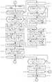
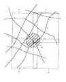
図2と図3はコントロール部9による地図表示制御処理を示すフローチャート、図4はユーザの現在位置周辺の道路を示す地図、図5は画像メモリ部6に記憶される画像の説明図、図6〜図8は表示部5の画面表示例の説明図であり、以下、これらの図を参照して上記した実施の形態の動作を説明する。
なお、最初、記憶部5には地図データが何も記憶されていないものとする。また、ユーザは図4のP点に居るものとする。
【0014】
(1)地図スクロール開始前(図6(1)参照)
地図表示機能付携帯電話端末1の電源をオンすると、GPS受信部2は衛星航法により定期的に現在位置を検出する。コントロール部9は初めに地図スクロールモードをオフし(ステップS10)、GPS受信部2から現在位置データを入力する(ステップS11)。そして、現在位置の初めての入力なので(ステップS12でYES)、ステップS14へ進み、現在位置周辺(現在位置を含むエリアと、当該エリアを取り囲むエリア)の地図データが全て記憶部6に揃っているかチェックする。NOであったとすると、通信部9を制御して、情報配信装置40宛に不足分のエリア情報を含む地図データ要求信号を無線回線を介して移動網20の側に送信させる。
【0015】
地図データ要求信号は移動網20とインターネット30を経由して情報配信装置40に送信され、情報配信部42は地図データ要求信号を受信すると、地図データ蓄積部41の中から要求された各エリアの地図データを読み出し、要求元に返信する。返信された地図データはインターネット30と移動網20を経由して最後に無線回線を介して通信部8で受信され、コントロール部9へ出力される。コントロール部9は返信された地図データを記憶部5に追加して記憶させる(ステップS15)。次に、コントロール部9は記憶部5に記憶された現在位置周辺の地図データを用いて、現在位置を中心とし、北を上向きにした地図画像を画像メモリ部6の第1記憶領域6aに描画し、第2記憶領域6bの内、第1記憶領域6aに描画された地図画像上の現在位置に対応する箇所(ここでは第2記憶領域6bの中心)に現在位置マークを描画する(ステップS16、S17)。合成部7は画像メモリ部6の第1記憶領域6aに記憶された地図画像の上に第2記憶領域6bに記憶された現在位置マークの画像を合成し、所定の映像信号に変換して表示部4へ出力して画面表示させる(ステップS18)。
【0016】
この結果、画面4Aには図6(1)に示す如く、図4の現在位置Pを中心とした1画面分の地図画像MI(図4の枠線Aの範囲)が現在位置マークMMとともに表示されるので、ユーザは現在位置がどこであるか地図上で簡単に確認できる。
【0017】
ステップS18のあと、コントロール部9は操作部3で上スクロールキー3a、下スクロールキー3b、左スクロールキー3c、右スクロールキー3dのいずれか1つが押されたかチェックし(ステップS19)、NOであればステップS11に戻ってGPS受信部2から次の現在位置データを入力する。そして、初めての入力でないので(ステップS12でNO)、前回入力した現在位置から一定距離(例えば5m)以上変化したかチェックし(ステップS13)、NOであればステップS19へ進み同様の処理を繰り返す。その後、若しステップS13でYESとなったときは現在位置を中心とし、北を上向きにした地図画像を画像メモリ部6の第1記憶領域6aに描画し直し(ステップS14〜16)、また第2記憶領域6bの中心に現在位置マークを描画し直す(ステップS17)。よって、画面4Aの地図画像はユーザが徒歩で移動した分だけ移動する。
【0018】
(2)地図スクロール操作開始(図6(2)〜図6(4)、図7(1)参照)
ユーザが図4のP点に居るとして、図6(1)の画面4Aの右下隅を中心とした図4の斜線Q1で示す範囲の地図を見たい場合、まず、左スクロールキー3aを押し続ける。コントロール部9は左スクロールキー3aが押されると、ステップS19でYESと判断し、地図スクロールモードをオンする(ステップS20)。そして、その時点の現在位置をスクロールカーソル位置座標の初期値SDK0として登録するとともに、現在のスクロールカーソル位置座標SKDをSDK0とする(ステップS21)。また、SDK0とSDKの間の地理的距離を計算してLとする(図3のステップS30)。
【0019】
次に、コントロール部9はSDKの示す位置(図4の点SK0参照)が第1記憶領域6aに描画された地図画像の端に来ているかチェックし(ステップS31)、最初はNOなので、第1記憶領域6aに描画された地図画像のエリアにSDK0の位置が入っているかチェックする(ステップS32)。YESなので、第2記憶領域6bの内、第1記憶領域6aの地図画像上でのSDKの示すスクロールカーソル位置とSDK0の示す地図スクロール操作開始時の現在位置に各々対応する2点間に所定の色(ここでは赤色)の直線を描画し(ステップS33)、第2記憶領域6bの内、第1記憶領域6aの地図画像上でのSDK0の示す地図スクロール操作開始時の現在位置とSDKの示すスクロールカーソル位置に各々対応する位置に現在位置マークとスクロールカーソル(ここでは星形とする)を描画し(ステップS34)、更に、第2記憶領域6bの右下隅にスクロール操作が開始時点での現在位置とスクロール位置との間の地理的距離を示す文字(最初は0m)を描画する(ステップS35)。
【0020】
合成部7が画像メモリ部6の第1記憶領域6aに記憶された地図画像の上に第2記憶領域6bに記憶された現在位置マーク、スクロールカーソル、文字等の画像を合成し、所定の映像信号に変換して表示部4へ出力して画面表示させる(ステップS36)。
この結果、画面4Aには図6(2)に示す如く、地図画像MIは変わらないが、現在位置マークMMの上にスクロールカーソルSKMが重ねて表示される。また、スクロールカーソル位置と地図スクロール開始操作時点での現在位置の間の地理的距離を示す文字DM(最初は0m)が画面4Aの右下隅に表示される。
【0021】
ステップS36のあと、コントロール部9は操作部3でクリアキーが押されたか(ステップS37)、または上スクロールキー3a、下スクロールキー3b、左スクロールキー3c、右スクロールキー3dのいずれか1つが押されているかチェックする(ステップS38)。左スクロールキー3cが押されていたとき、SDKの値を西の方向へ一定量分(ここでは一例として5m分とする)だけ変化させる。ステップS39)。そして、ステップS30に戻り、前述と同様の処理を行い、SDK0とSDKの間の地理的距離を計算してLとし、SDKの位置がまだ第1記憶領域6aの地図画像のエリアに入っており該地図画像の端に来ていないとき、第2記憶領域6bの内、第1記憶領域6aの地図画像上でのSDKの示すスクロールカーソル位置とSDK0の示す地図スクロール操作開始時の現在位置に各々対応する2点間に所定の色の直線を描画し(ステップS33。図5のLM参照)、第2記憶領域6bの内、第1記憶領域6aの地図画像上でのSDK0の示すスクロール操作開始時の現在位置とSDKの示すスクロールカーソル位置に各々対応する位置に現在位置マークとスクロールカーソルを描画し(ステップS34。図5のMM、SKM参照)、更に、第2記憶領域6bの右下隅にスクロール操作が開始時点での現在位置とスクロール位置との間の地理的距離を示す文字(5m)を描画する(ステップS35。図5のDM参照)。合成部7は画像メモリ部6の第1記憶領域6aに記憶された地図画像(図5のMI参照)の上に第2記憶領域6bに記憶された現在位置マークの画像を合成し、所定の映像信号に変換して表示部4へ出力して画面表示させる(ステップS36)。
【0022】
その後もユーザが左スクロールキー3cを押し続けると画面4Aの地図画像上でスクロールカーソルSKMが左方へ移動し、Lが50mになったとき(図4の点SK1参照)、画面4Aには図6(3)に示す如く、地図画像MIは変わらないが、現在位置マークMM(地図スクロール操作開始時点の現在位置を示す)の西方(画面上で左方)にスクロールカーソルSKMが表示され、かつ、現在位置マークMMとスクロールカーソルSKMを結ぶ直線LMも表示される。スクロールカーソル位置と地図スクロール開始操作時点での現在位置の間の地理的距離を示す文字DMが画面4Aの右下隅に表示される。
このあと、ユーザが左スクロールキー3cに代えて下スクロールキー3bを押し続けると、コントロール部9はステップS39の処理をする度にSDKの値を南の方向へ一定量分(ここでは一例として5m分)ずつ変化させるので、画面4Aの地図画像上でスクロールカーソルSKMが下方へ移動し、Lが200mになったとき(図4の点SK2参照)、画面4Aは図6(4)に示す如くなる。
【0023】
(3)地図スクロール(図7(1)、図7(2)参照)
このあと、ユーザが下スクロールキー3bに代えて左スクロールキー3cを押し続けると、コントロール部9はステップS39の処理をする度にSDKの値を西の方向へ一定量分(5m分)ずつ変化させるので、画面4Aの地図画像MIの上でスクロールカーソルSKMが左方へ移動する。スクロールカーソルSKDが地図画像MIの端に来ると(図7(1)参照)、SKDの位置が第1記憶領域6aに描画された地図画像のエリアの端に来るので(図4の点SK3参照)、コントロール部9は図3のステップS31でYESと判断する。このとき、スクロールカーソル位置の周辺(スクロールカーソル位置を含むエリアと、当該エリアを取り囲むエリア)の地図データが全て記憶部6に揃っているかチェックし(ステップS40)、若し不足分が有れば外部の情報配信装置40に要求して取得するが(ステップS41)、ここではステップS40でYESであったとすると、記憶部5に記憶されたスクロールカーソル位置周辺の地図データを用いて、スクロールカーソル位置を中心とし、北を上向きにした地図画像を画像メモリ部6の第1記憶領域6aに描画する(ステップS42。図4の枠線Eの範囲)。
【0024】
続いて、第1記憶領域6aに描画された地図画像のエリアにSDK0の位置が入っているかチェックする(ステップS32)。YESとすると、第2記憶領域6bの内、第1記憶領域6aの地図画像上でのSDKの示すスクロールカーソル位置とSDK0の示す地図スクロール操作開始時の現在位置に各々対応する2点間に所定の色の直線を描画し(ステップS33)、第2記憶領域6bの内、第1記憶領域6aの地図画像上でのSDK0の示す地図スクロール操作開始時の現在位置とSDKの示すスクロールカーソル位置に各々対応する位置に現在位置マークとスクロールカーソルを描画し(ステップS34)、更に、第2記憶領域6bの右下隅にスクロール操作が開始時点での現在位置とスクロール位置との間の地理的距離を示す文字を描画する(ステップS35)。
【0025】
合成部7が画像メモリ部6の第1記憶領域6aに記憶された地図画像の上に第2記憶領域6bに記憶された現在位置マーク、スクロールカーソル、直線、文字の画像を合成し、所定の映像信号に変換して表示部4へ出力して画面表示させる(ステップS36)。
この結果、画面4Aには図7(2)に示す如く、現在のスクロールカーソル位置(図4の点SK3参照)を中心とする地図画像MIが現在位置マークMM及びスクロールカーソルSKMとともに表示される。これにより、図4のQ1に示す所望の範囲の地図画像を一度に見ることができる。画面4Aにはスクロールカーソル位置と地図スクロール開始操作時点での現在位置の間の地理的距離を示す文字DM(250m)が表示されているので、現在位置からスクロールカーソルSKMの位置までの距離も判り、また、直線LMにより、スクロールカーソルSKMから見て地図スクロール操作開始時点での現在位置がどの方向であるかも簡単に判る。
【0026】
(4)地図スクロール操作の継続(図7(3)、図7(4)、図8(1)参照)
次に、ユーザが画面4Aの右下隅を中心とした図4の斜線Q2で示す範囲の地図を見たい場合、左スクロールキー3cと下スクロールキー3dを押して地図スクロール操作をすれば良い。ステップS36のあと、コントロール部9は操作部3でクリアキーが押されたか(ステップS37)、または上スクロールキー3a、下スクロールキー3b、左スクロールキー3c、右スクロールキー3dのいずれか1つが押されているかチェックする(ステップS38)。左スクロールキー3cが押されていたとき、SDKの値を西の方向へ一定量分(5m分)だけ変化させる(ステップS39)。そして、ステップS30に戻り、前述と同様の処理を行い、SDK0とSDKの間の地理的距離を計算してLとし、SDKの位置がまだ第1記憶領域6aの地図画像に入っており該地図画像の端に来ていないとき、第2記憶領域6bの内、第1記憶領域6aの地図画像上でのSDKの示すスクロールカーソル位置とSDK0の示す地図スクロール操作開始時の現在位置に各々対応する2点間に所定の色の直線を描画し(ステップS33)、第2記憶領域6bの内、第1記憶領域6aの地図画像上でのSDK0の示す地図スクロール操作開始時の現在位置とSDKの示すスクロールカーソル位置に各々対応する位置に現在位置マークとスクロールカーソルを描画し(ステップS34)、更に、第2記憶領域6bの右下隅に地図スクロール操作開始時点での現在位置とスクロールカーソル位置との間の地理的距離を示す文字を描画する(ステップS35)。合成部7は画像メモリ部6の第1記憶領域6aに記憶された地図画像の上に第2記憶領域6bに記憶された現在位置マーク、スクロールカーソル、直線、文字の画像を合成し、所定の映像信号に変換して表示部4へ出力して画面表示させる(ステップS36)。
【0027】
その後もユーザが左スクロールキー3cを押し続けると画面4Aの地図画像上でスクロールカーソルSKMが左方へ移動し、Lが300mになったとき、画面4Aには図7(3)に示す如く、地図画像MIは変わらないが、画面中心から少し西方(画面上で左方)にスクロールカーソルSKMが表示される(図4の点SK4参照)。
このあと、ユーザが左スクロールキー3cに代えて下スクロールキー3bを押し続けると、コントロール部9はステップS39の処理をする度にSDKの値を南の方向へ一定量分(例えば、5m分)ずつ変化させるので、画面4Aの地図画像上でスクロールカーソルSKMが下方へ移動し、Lが450mになったとき、画面4Aは図7(4)に示す如くなる(図4の点SK5参照)。
【0028】
(5)地図スクロール(図8(1)、図8(2)参照)
このあと、ユーザが下スクロールキー3bに代えて左スクロールキー3cを押し続けると、コントロール部9はステップS39の処理をする度にSDKの値を西の方向へ一定量分(5m分)ずつ変化させるので、画面4Aの地図画像MIの上でスクロールカーソルSKMが左方へ移動する。スクロールカーソルSKDが地図画像MIの端に来ると(図8(1)参照)、SKDの位置が第1記憶領域6aに描画された地図画像の端に来るので(図4の点SK6参照)、コントロール部9は図3のステップS31でYESと判断する。このとき、コントロール部9はスクロールカーソル位置の周辺(スクロールカーソルを含むエリアと、当該エリアを取り囲むエリア)の地図データが全て記憶部6に揃っているかチェックし(ステップS40)、若し不足分が有れば外部の情報配信装置40に要求して取得するが(ステップS41)、ここではステップS40でYESであったとすると、記憶部5に記憶されたSKD位置周辺の地図データを用いて、スクロールカーソル位置を中心とし、北を上向きにした地図画像を画像メモリ部6の第1記憶領域6aに描画する(ステップS42。図4の枠線Fの範囲)。
【0029】
続いて、第1記憶領域6aに描画された地図画像のエリアにSDK0の位置が入っているかチェックする(ステップS32)。今度はNOなので、第2記憶領域6bの内、第1記憶領域6aの地図画像上でのSDKの示すスクロールカーソル位置に対応する位置から、第1記憶領域6aの地図画像上でのSDKの示すスクロールカーソル位置からSDK0の位置を見た方向へ、所定の色の直線を描画し(ステップS43)、第2記憶領域6bの内、第1記憶領域6aの地図画像上でのSDKの示すスクロールカーソル位置に対応する位置にスクロールカーソルを描画し(ステップS44)、更に、第2記憶領域6bの右下隅にスクロール操作が開始時点での現在位置とスクロール位置との間の地理的距離を示す文字を描画する(ステップS35)。
【0030】
合成部7が画像メモリ部6の第1記憶領域6aに記憶された地図画像の上に第2記憶領域6bに記憶されたスクロールカーソル、直線、文字の画像を合成し、所定の映像信号に変換して表示部4へ出力して画面表示させる(ステップS36)。
この結果、画面4Aには図8(2)に示す如く、現在のスクロールカーソル位置を中心とする地図画像MIがスクロールカーソルSKMとともに表示される。これにより、図4のQ2に示す所望の範囲の地図画像を一度に見ることができる。画面4Aにはスクロールカーソル位置と地図スクロール開始操作時点での現在位置の間の地理的距離を示す文字DM(550m)が表示されているので、現在位置からスクロールカーソルSKMの位置までの距離も判り、また、直線LMにより、スクロールカーソルSKMから見て地図スクロール開始操作時点での現在位置がどの方向であるかも簡単に判る。
【0031】
以上の如く所望範囲の地図を確認後、地図スクロールモードをオフしたい場合、操作部3で図示しないクリアキーを押す。すると、コントロール部9はステップS37でYESと判断し、図2のステップS10へ進んで地図スクロールモードをオフしたのち、前述した(1)と同様にして現在位置周辺の地図画像の表示を行う。
【0032】
この実施の形態によれば、予め、現在位置周辺の地図画像が表示されている状態で地図スクロール操作を開始すると、地図画像は変わらずに該地図画像に重ねたスクロールカーソルが移動し、地図を見たい所望の範囲内でかつ地図画像の端までスクロールカーソルが移動すると、スクロールカーソルを中心とした地図画像に切り替わる。これより、ユーザは所望の範囲の地図を一度に見ることができる。また、スクロールカーソルの位置からスクロール操作開始時点の現在位置に向けた直線が地図画像に重ねて表示されるので、スクロールカーソルの位置から見たスクロール操作開始時点の現在位置の方向が一目で判る。更に、スクロールカーソルの位置からスクロール操作開始時点の現在位置の間の地理的距離が表示されるので、スクロール操作開始時点の現在位置からスクロールカーソルまでどれくらい離れているかも簡単に知ることができる。
【0033】
なお、上記した実施の形態では、地図スクロール操作中、スクロールカーソルが地図画像の端に来るまでは地図画像及び現在位置マークは変化しないようにしたが、地図スクロール操作中にユーザが移動している場合に、現在位置の変化に応じて地図画像を移動し、現在位置がどこか地図上で正確に確認できるようにしても良い。
具体的には、コントロール部9による図2と図3の表示制御処理を図9、図10のように変更すれば良い(なお、図2、図3と同じ処理には同一のステップ番号が付してある)。最初のステップS10´では地図スクロールモードをオフするとともに、地図スクロール操作開始後、まだスクロールカーソルが地図画像の端に来る前であることを示すためのフラグF(0;スクロールカーソルが地図画像の端に来る前、1;スクロールカーソルが地図画像の端に来たあと)を0としておく。そして、地図スクロール操作開始後、ステップS21´では、現在位置をSKDとし、図10のステップS30´ではSDKと現在位置間の地理的距離を計算してLとする。また、ステップS32´では第1記憶領域6aに描画された地図画像のエリアに現在位置が入っているかチェックし、ステップS33´では第2記憶領域6bの内、第1記憶領域6aの地図画像上のスクロールカーソル位置と現在位置に各々対応する2点間に所定の色の直線を描画し、ステップS34´では、第2記憶領域6bの内、第1記憶領域6aの地図画像上での現在位置とスクロールカーソル位置に各々対応する位置に現在位置マークとスクロールカーソルを描画するようにする。更に、ステップS43´では第2記憶領域6bの内、第1記憶領域6aの地図画像上でのSDKの示すスクロールカーソル位置に対応する位置から、第1記憶領域6aの地図画像上でのSDKの示すスクロールカーソル位置から現在位置を見た方向へ、所定の色の直線を描画するようにする。
【0034】
そして、図10のステップS39の処理のあとFをチェックし(ステップS45)、0であれば図9のステップS11に戻って現在位置を入力し、前回入力した現在位置から一定距離以上変化していれば(ステップS13でYES)、第1記憶領域6aに現在位置を中心とする地図画像を描画し直す(ステップS16)。そして、地図スクロールモードがオン中かチェックし(ステップS22)、NOであればステップS17へ進むが、YESであれば図10のステップS30´の側に進むようにして、地図スクロール操作中であっても現在位置の変化に応じて地図画像が移動するようにする。例えば、ユーザが西に向かって移動しているとき、画面4Aの中央に現在位置マークが表示されたまま地図画像はスクロールカーソルとともに右に移動することになり、移動中も現在位置がどこであるか地図上で正確に確認できる。この場合、地図画像はユーザが一定距離移動する毎に描画し直されるだけであり、連続的に再描画する訳ではないので、コントロール部9の処理負担は少ない(ステップS13でNOのとき、地図スクロールモードがオフしていればステップS23でYESと判断してステップS19へ進み、ステップS23でNOであれば図10のステップS30´へ進む)。画面4Aには移動中の現在位置とスクロールカーソルを結ぶ直線及び移動中の現在位置とスクロールカーソル間の距離が表示されるので、スクロールカーソル位置から見た現在位置の方向と現在位置までの距離も正確に判る。
【0035】
そして、地図スクロール操作により、スクロールカーソルが画面4Aの地図画像の端に来たときはFを1としたあと(図10のステップS31でYES、ステップS47)、ステップS40へ進み、スクロールカーソル位置を中心とする北を上向きとした1画面分の地図画像を第1記憶領域6aに描画する(ステップS42)。そして、その後はステップS45でFが1と判断されるので、コントロール部9はGPS受信部2から現在位置を入力したあと(ステップS46)、ステップS30´へ進み、スクロールカーソル位置と現在位置間の地理的距離Lを計算したのち、第2記憶領域6bに現在位置マーク、スクロールカーソル、スクロールカーソル位置から現在位置に向けた直線、スクロールカーソル位置と現在位置間の地理的距離を描画し(ステップS31〜35、またはステップS31、S32´、S43´、S44、S35)、第1記憶領域6aの地図画像の上に現在位置マーク、スクロールカーソル、スクロールカーソル位置から現在位置に向けた直線、スクロールカーソル位置と現在位置間の距離を重ねた画像を表示させる(ステップS36)。
【0036】
図9、図10の変形例によれば、地図スクロール操作中にユーザが移動している場合に、現在位置の変化に応じて地図画像が移動するので、現在位置がどこか地図上で正確に確認できるようになり、またスクロールカーソル位置から見た現在位置の方向と、スクロールカーソル位置と現在位置間の距離も正確に判る。
【0037】
なお、上記した実施の形態では、地図表示機能付携帯電話端末を例に挙げて説明したが、本発明は何らこれに限定されず、地図表示機能付携帯情報端末(PDA)などにも同様に適用できる。また、地図データは外部から取得するようにしたが、記憶部をICメモリカードで構成し、初めから記憶部に記憶させておくようにしても良い。
【0038】
【発明の効果】
本発明によれば、スクロールカーソル移動操作を開始して地図画像上でスクロールカーソルをユーザ所望の範囲の方向に移動させていくと、スクロールカーソルが地図画像の内、ユーザ所望の範囲に入っている端まで来たところで、スクロールカーソル周辺の一定範囲の地図画像に切り替わって表示されるので、所望の範囲の地図を一目で視認できる。
【図面の簡単な説明】
【図1】本発明の一つの実施の形態に係る地図表示機能付携帯電話端末の地図表示系の構成を示すブロック図である。
【図2】図1中のコントロール部の地図表示制御処理を示すフローチャートである。
【図3】図1中のコントロール部の地図表示制御処理を示すフローチャートである。
【図4】ユーザの現在位置周辺の道路を示す地図である。
【図5】図1中の画像メモリ部に描画される画像の説明図である。
【図6】図1中の表示部の表示例の説明図である。
【図7】図1中の表示部の表示例の説明図である。
【図8】図1中の表示部の表示例の説明図である。
【図9】図1の変形例に係る地図表示制御処理を示すフローチャートである。
【図10】図1の変形例に係る地図表示制御処理を示すフローチャートである。
【図11】ユーザの現在位置周辺の道路地図である。
【図12】従来の地図スクロール方法の問題点の説明図である。
【符号の説明】
1 地図表示機能付携帯電話端末 2 GPS受信部
3 操作部 4 表示部
5 記憶部 6 画像メモリ部
9 コントロール部[0001]
BACKGROUND OF THE INVENTION
The present invention relates to a portable map display device, and more particularly to a portable map display device capable of scrolling a map image.
[0002]
[Prior art]
There is a portable map display device that allows a pedestrian to check the current position on a map while carrying it. This portable map display device detects a current position by a small GPS receiver, and uses map data stored in an IC memory card or map data obtained from an external map data distribution computer system via a network by communication, A map image of a certain range around the position is drawn together with the current position mark and displayed on the liquid crystal display.
[0003]
When the user is at the point P as viewed on the road map shown in FIG. 11, for example, as shown in FIG. 12 (1), the screen has a certain range centered on the current position mark MM (the range of the frame A in FIG. 11). Since the map image MI with the north facing upward is displayed, the user can confirm on the map where the current position is and what is around it.
[0004]
Since the portable map display device has a map scroll function as in the case of the on-vehicle map display device, a map scroll operation may be performed to view a map outside the range of the map image displayed on the screen.
However, since the map drawing speed is sufficiently fast in the in-vehicle map display device, the map image can be continuously scrolled according to the scrolling operation, but the map drawing speed is generally slow in the portable map display device, Instead of scrolling continuously, the drawing area is changed rapidly.
[0005]
Specifically, in the display state of FIG. 12A, when the user wants to see the map in the hatched area Q of FIG. 11, first, the left scroll key is pressed once. Then, the map image of the range of the frame line B shifted from the frame line A in FIG. 11 to the west by about 4/5 of the width in the east-west direction of the frame line A is drawn and displayed (see FIG. 12B). ). Next, press the down scroll key once. Then, a map image in a range of the frame line C shifted from the frame line B of FIG. 11 by about 4/5 of the width in the north-south direction of the frame line B is drawn and displayed (see FIG. 12 (3)). ). Then press the right scroll key once. Then, a map image in the range of the frame line D shifted from the frame line C in FIG. 11 to the east by about 4/5 of the width in the east-west direction of the frame line B is drawn and displayed (see FIG. 12 (4)). ). Thereby, the map of the range Q desired by the user can be viewed.
[0006]
[Problems to be solved by the invention]
However, in the above-described conventional portable map display device, since the map scroll is skipped in the east-west direction or the north-south direction, when the desired range is Q in FIG. 11, the desired range can be viewed all at once. This is not possible, and the desired range can be seen only partly by the map scrolling operation (q in FIG. 12).1 ~ QFour There was a problem that it was difficult to understand the geographical situation of the desired range.
An object of the present invention is to provide a portable map display device that allows a user to see a map of a desired range at a glance in view of the above-described problems of the prior art.
[0007]
[Means for Solving the Problems]
According to the first aspect of the present invention, current position detecting means for detecting the current position, display means for displaying a map image together with the current position mark and the scroll cursor, scroll operating means for moving the scroll cursor, scroll cursor When the move operation starts, the current position at that time is set as the initial value, and the scroll cursor position coordinates that change according to the scroll cursor move operation are calculated.To detect the scroll cursor position on the display screen. Before the scroll cursor position coordinate calculating means is started and the scroll cursor moving operation is started, together with a current position mark obtained by superimposing a map image of a certain range around the current position on the corresponding position of the map image using map data. When the scroll cursor movement operation is started and displayed on the display means, the scroll cursor is moved to the corresponding location on the map image displayed at the start of the scroll cursor movement operation until the scroll cursor position reaches the end of the map image on the screen. When the scroll cursor position comes to the edge of the map image on the screen, the map image in a certain range around the scroll cursor position at that time is displayed., With the scroll cursor at the center of the screen The present invention is characterized by comprising a map display control means for redrawing and displaying on the display means together with a current position mark and a scroll cursor superimposed on the corresponding part of the map image.
According to a third aspect of the present invention, current position detecting means for detecting the current position, display means capable of displaying a map image together with the current position mark and the scroll cursor, scroll operating means for moving the scroll cursor, and scroll cursor When the move operation starts, the current position at that time is set as the initial value and the scroll cursor position coordinates are calculated according to the scroll cursor move operation.To detect the scroll cursor position on the display screen. Before the scroll cursor position coordinate calculating means is started and the scroll cursor moving operation is started, together with a current position mark obtained by superimposing a map image of a certain range around the current position on the corresponding position of the map image using map data. When the scroll cursor movement operation is started and displayed on the display means, the scroll cursor and scroll cursor are moved to the corresponding part of the map image at the start of the scroll cursor movement operation until the scroll cursor position reaches the end of the map image on the screen. When a line connecting the current position at the start of the move operation and the scroll cursor position is superimposed and displayed on the display means, when the scroll cursor position comes to the edge of the map image on the screen, the surrounding area around the scroll cursor position at that time is constant. Map image of range, Redraw with the scroll cursor at the center of the screen A map display control means for displaying on the display means together with a current position mark, a scroll cursor, and a straight line from the scroll cursor position to the current position at the start of the scroll cursor moving operation. It is characterized by that.
In the present invention, the current position detecting means for detecting the current position, the display means capable of displaying the map image together with the current position mark and the scroll cursor, the scroll operation means for moving the scroll cursor, and the scroll cursor When the move operation starts, the current position at that time is set as the initial value and the scroll cursor position coordinates are calculated according to the scroll cursor move operation.To detect the scroll cursor position on the display screen. Before the scroll cursor position coordinate calculating means is started and the scroll cursor moving operation is started, together with a current position mark obtained by superimposing a map image of a certain range around the current position on the corresponding position of the map image using map data. When the scroll cursor movement operation is started by displaying on the display means, the current position mark and the scroll are scrolled to the corresponding part of the map image in a certain range around the current position until the scroll cursor position comes to the end of the map image on the screen. When the image where the cursor is superimposed is displayed on the display means and the scroll cursor position comes to the edge of the map image on the screen, a map image of a certain range around the scroll cursor position at that time is displayed., With the scroll cursor at the center of the screen The present invention is characterized by comprising a map display control means for redrawing and displaying on the display means together with a current position mark and a scroll cursor superimposed on the corresponding part of the map image.
In the present invention, the present position detecting means for detecting the present position, the display means capable of displaying the map image together with the present position mark and the scroll cursor, the scroll operation means for moving the scroll cursor, and the scroll cursor When the move operation starts, the current position at that time is set as the initial value and the scroll cursor position coordinates are calculated according to the scroll cursor move operation.To detect the scroll cursor position on the display screen. Before the scroll cursor position coordinate calculating means is started and the scroll cursor moving operation is started, together with a current position mark obtained by superimposing a map image of a certain range around the current position on the corresponding position of the map image using map data. When the scroll cursor movement operation is started by displaying on the display means, the current position mark and the scroll are scrolled to the corresponding part of the map image in a certain range around the current position until the scroll cursor position comes to the end of the map image on the screen. When the image that overlaps the cursor and the straight line connecting the current position and the scroll cursor is displayed on the display means and the scroll cursor position comes to the end of the map image on the screen, a certain range around the scroll cursor position at that time Map image, With the scroll cursor at the center of the screen A map display control means for redrawing and displaying on the display means together with a current position mark, a scroll cursor, and a straight line from the scroll cursor position to the current position, which are superimposed on a corresponding portion of the map image. Yes.
In
In
[0008]
DETAILED DESCRIPTION OF THE INVENTION
Next, one embodiment of the present invention will be described with reference to FIG. FIG. 1 is a block diagram showing a configuration of a part related to a map display function, among the mobile phone terminals with a map display function according to the present invention.
1 is a mobile phone terminal with a map display function as an example of a mobile map display device, 20 is a mobile network capable of data communication with a mobile phone terminal with a map display function, 30 is the Internet connected to the mobile network, and 40 is connected to the Internet. An information distribution apparatus (information distribution computer system) operated by a content distribution company, a map
[0009]
Of the
[0010]
The control unit 9 controls the
[0011]
Further, when one of the up scroll key 3a, down scroll key 3b, left scroll key 3c, and right scroll key 3d of the
[0012]
Thereafter, when the scroll cursor position reaches the end of the map image in the first storage area 6a, the map data around the scroll cursor position stored in the
[0013]
2 and 3 are flowcharts showing map display control processing by the control unit 9, FIG. 4 is a map showing roads around the current position of the user, FIG. 5 is an explanatory diagram of images stored in the
First, it is assumed that no map data is stored in the
[0014]
(1) Before starting map scrolling (see Fig. 6 (1))
When the
[0015]
The map data request signal is transmitted to the
[0016]
As a result, as shown in FIG. 6A, the screen image 4A displays a map image MI (range of the frame A in FIG. 4) centered on the current position P in FIG. 4 together with the current position mark MM. Therefore, the user can easily confirm on the map where the current position is.
[0017]
After step S18, the control unit 9 checks whether any one of the up scroll key 3a, the down scroll key 3b, the left scroll key 3c, and the
[0018]
(2) Start of map scroll operation (see FIGS. 6 (2) to 6 (4), FIG. 7 (1))
Assuming that the user is at point P in FIG. 4, the slanted line Q in FIG. 4 centering on the lower right corner of the screen 4A in FIG.1 When the user wants to see the map in the range indicated by (1), first, the user keeps pressing the left scroll key 3a. When the left scroll key 3a is pressed, the control unit 9 determines YES in step S19 and turns on the map scroll mode (step S20). Then, the current position at that time is set to the initial value SDK of the scroll cursor position coordinates.0 And register the current scroll cursor position coordinates SKD as SDK0 (Step S21). SDK0 The geographical distance between the CPU and the SDK is calculated as L (step S30 in FIG. 3).
[0019]
Next, the control unit 9 moves the position indicated by the SDK (point SK in FIG. 4).0 Check) is at the end of the map image drawn in the first storage area 6a (step S31). Since NO is initially determined, the SDK is placed in the area of the map image drawn in the first storage area 6a.0 Is checked (step S32). Since the answer is YES, the scroll cursor position and the SDK indicated by the SDK on the map image in the first storage area 6a in the second storage area 6b0 A straight line of a predetermined color (here, red) is drawn between the two points corresponding to the current position at the start of the map scroll operation indicated by (step S33), and the first storage area 6a in the second storage area 6b is drawn. SDK on the map image0 A current position mark and a scroll cursor (here, a star shape) are drawn at positions corresponding to the current position at the start of the map scroll operation indicated by and the scroll cursor position indicated by the SDK (step S34), and further stored in the second memory. A character (initially 0 m) indicating the geographical distance between the current position and the scroll position at the start of the scroll operation is drawn in the lower right corner of the area 6b (step S35).
[0020]
The combining
As a result, as shown in FIG. 6B, the map image MI is not changed on the screen 4A, but the scroll cursor SKM is displayed over the current position mark MM. In addition, a character DM (initially 0 m) indicating the geographical distance between the scroll cursor position and the current position at the time of the map scroll start operation is displayed in the lower right corner of the screen 4A.
[0021]
After step S36, the control unit 9 has pressed the clear key on the operation unit 3 (step S37), or pressed any one of the up scroll key 3a, the down scroll key 3b, the left scroll key 3c, and the
[0022]
Thereafter, when the user continues to press the left scroll key 3c, the scroll cursor SKM moves to the left on the map image on the screen 4A, and when L becomes 50 m (point SK in FIG. 4).1 As shown in FIG. 6 (3), the map image MI does not change on the screen 4A, but to the west of the current position mark MM (indicating the current position at the start of the map scroll operation) (to the left on the screen). A scroll cursor SKM is displayed, and a straight line LM connecting the current position mark MM and the scroll cursor SKM is also displayed. A character DM indicating the geographical distance between the scroll cursor position and the current position at the time of the map scroll start operation is displayed in the lower right corner of the screen 4A.
Thereafter, when the user continues to press the down scroll key 3b instead of the left scroll key 3c, the control unit 9 increases the value of SDK by a certain amount in the south direction every time the process of step S39 is performed (here, 5 m as an example). Since the scroll cursor SKM moves downward on the map image on the screen 4A and L becomes 200 m (point SK in FIG. 4).2 The screen 4A is as shown in FIG. 6 (4).
[0023]
(3) Map scroll (see Fig. 7 (1), Fig. 7 (2))
Thereafter, when the user continues to press the left scroll key 3c instead of the down scroll key 3b, the control unit 9 changes the value of SDK by a certain amount (5 m) in the west direction every time the process of step S39 is performed. Therefore, the scroll cursor SKM moves to the left on the map image MI on the screen 4A. When the scroll cursor SKD comes to the end of the map image MI (see FIG. 7 (1)), the position of the SKD comes to the end of the area of the map image drawn in the first storage area 6a (point SK in FIG. 4).Three The control unit 9 determines YES in step S31 of FIG. At this time, it is checked whether all the map data around the scroll cursor position (the area including the scroll cursor position and the area surrounding the area) are stored in the storage unit 6 (step S40). Although it requests and acquires from the external information delivery apparatus 40 (step S41), if it is YES here in step S40, the scroll cursor position will be obtained using the map data around the scroll cursor position stored in the
[0024]
Subsequently, the area of the map image drawn in the first storage area 6a is SDK0 Is checked (step S32). If YES, the scroll cursor position and the SDK indicated by the SDK on the map image of the first storage area 6a in the second storage area 6b0 A straight line of a predetermined color is drawn between two points respectively corresponding to the current position at the start of the map scroll operation indicated by (step S33), and the map image in the first storage area 6a in the second storage area 6b is drawn. SDK0 A current position mark and a scroll cursor are drawn at positions corresponding to the current position at the start of the map scroll operation indicated by and the scroll cursor position indicated by the SDK (step S34), and the scroll operation is further performed at the lower right corner of the second storage area 6b. The character which shows the geographical distance between the present position and scroll position at the time of starting is drawn (step S35).
[0025]
The combining
As a result, as shown in FIG. 7 (2), the current scroll cursor position (point SK in FIG. 4) is displayed on the screen 4A.Three A map image MI centered on (see) is displayed together with a current position mark MM and a scroll cursor SKM. As a result, Q in FIG.1 It is possible to view a map image of a desired range shown in FIG. Since the character DM (250 m) indicating the geographical distance between the scroll cursor position and the current position at the time of the map scroll start operation is displayed on the screen 4A, the distance from the current position to the position of the scroll cursor SKM is also known. In addition, the direction of the current position at the start of the map scroll operation as seen from the scroll cursor SKM can be easily determined by the straight line LM.
[0026]
(4) Continuation of map scrolling operation (see FIGS. 7 (3), 7 (4), and 8 (1))
Next, the user sees the diagonal line Q in FIG. 4 centered on the lower right corner of the screen 4A.2 When the user wishes to view the map in the range indicated by, the map scroll operation may be performed by pressing the left scroll key 3c and the down scroll key 3d. After step S36, the control unit 9 has pressed the clear key on the operation unit 3 (step S37), or pressed any one of the up scroll key 3a, the down scroll key 3b, the left scroll key 3c, and the
[0027]
Thereafter, when the user continues to press the left scroll key 3c, the scroll cursor SKM moves to the left on the map image on the screen 4A. When L becomes 300 m, the screen 4A has a screen as shown in FIG. Although the map image MI does not change, the scroll cursor SKM is displayed slightly westward (leftward on the screen) from the center of the screen (point SK in FIG. 4).Four reference).
Thereafter, when the user continues to press the down scroll key 3b instead of the left scroll key 3c, the control unit 9 increases the value of SDK by a certain amount (for example, 5 m) in the south direction every time the process of step S39 is performed. Since the scroll cursor SKM moves downward on the map image on the screen 4A and L becomes 450 m, the screen 4A becomes as shown in FIG. 7 (4) (point SK in FIG. 4).Five reference).
[0028]
(5) Map scroll (see Fig. 8 (1), Fig. 8 (2))
Thereafter, when the user continues to press the left scroll key 3c instead of the down scroll key 3b, the control unit 9 changes the value of SDK by a certain amount (5 m) in the west direction every time the process of step S39 is performed. Therefore, the scroll cursor SKM moves to the left on the map image MI on the screen 4A. When the scroll cursor SKD comes to the end of the map image MI (see FIG. 8 (1)), the position of the SKD comes to the end of the map image drawn in the first storage area 6a (point SK in FIG. 4).6 The control unit 9 determines YES in step S31 of FIG. At this time, the control unit 9 checks whether the map data around the scroll cursor position (the area including the scroll cursor and the area surrounding the area) are all stored in the storage unit 6 (step S40). If there is, the request is obtained from the external information distribution device 40 (step S41). Here, if YES in step S40, scrolling is performed using the map data around the SKD position stored in the
[0029]
Subsequently, the area of the map image drawn in the first storage area 6a is SDK0 Is checked (step S32). Since this time is NO, from the position corresponding to the scroll cursor position indicated by the SDK on the map image in the first storage area 6a in the second storage area 6b, the SDK is indicated on the map image in the first storage area 6a. SDK from scroll cursor position0 A straight line of a predetermined color is drawn in the direction of viewing the position (step S43), and the position corresponding to the scroll cursor position indicated by the SDK on the map image of the first storage area 6a in the second storage area 6b. A scroll cursor is drawn (step S44), and a character indicating the geographical distance between the current position and the scroll position at the start of the scroll operation is drawn in the lower right corner of the second storage area 6b (step S35). ).
[0030]
The combining
As a result, as shown in FIG. 8 (2), the map image MI centered on the current scroll cursor position is displayed on the screen 4A together with the scroll cursor SKM. As a result, Q in FIG.2 It is possible to view a map image of a desired range shown in FIG. Since the character DM (550 m) indicating the geographical distance between the scroll cursor position and the current position at the time of the map scroll start operation is displayed on the screen 4A, the distance from the current position to the position of the scroll cursor SKM is also known. In addition, the direction of the current position at the time of the map scroll start operation when viewed from the scroll cursor SKM can be easily determined by the straight line LM.
[0031]
When the map scroll mode is to be turned off after confirming the map in the desired range as described above, a clear key (not shown) is pressed on the
[0032]
According to this embodiment, when the map scroll operation is started in a state where the map image around the current position is displayed in advance, the scroll cursor superimposed on the map image is moved without changing the map image, and the map is moved. When the scroll cursor moves to the end of the map image within the desired range to be viewed, the map image is switched to the center of the scroll cursor. Thereby, the user can see a map of a desired range at a time. In addition, since a straight line from the position of the scroll cursor toward the current position at the start of the scroll operation is displayed superimposed on the map image, the direction of the current position at the start of the scroll operation as seen from the position of the scroll cursor can be seen at a glance. Further, since the geographical distance between the position of the scroll cursor and the current position at the start of the scroll operation is displayed, it is possible to easily know how far away from the current position at the start of the scroll operation to the scroll cursor.
[0033]
In the above-described embodiment, the map image and the current position mark are not changed until the scroll cursor comes to the end of the map image during the map scroll operation, but the user is moving during the map scroll operation. In this case, the map image may be moved in accordance with the change in the current position so that the current position can be accurately confirmed on the map.
Specifically, the display control processing of FIG. 2 and FIG. 3 by the control unit 9 may be changed as shown in FIG. 9 and FIG. 10 (note that the same step number is assigned to the same processing as FIG. 2 and FIG. 3). ) In the first step S10 ', the map scroll mode is turned off, and after starting the map scroll operation, a flag F (0; indicating that the scroll cursor is not yet at the end of the map image and the scroll cursor is at the end of the map image). 1 before moving to 1; after the scroll cursor has come to the end of the map image. Then, after starting the map scroll operation, the current position is set to SKD in step S21 ′, and the geographical distance between the SDK and the current position is calculated to be L in step S30 ′ of FIG. In step S32 ′, it is checked whether the current position is in the area of the map image drawn in the first storage area 6a. In step S33 ′, the map image in the first storage area 6a in the second storage area 6b is checked. A straight line of a predetermined color is drawn between two points respectively corresponding to the scroll cursor position and the current position, and in step S34 ', the current position on the map image of the first storage area 6a in the second storage area 6b. The current position mark and the scroll cursor are drawn at positions corresponding to the scroll cursor position. Further, in step S43 ′, the SDK on the map image in the first storage area 6a is selected from the position corresponding to the scroll cursor position indicated by the SDK on the map image in the first storage area 6a in the second storage area 6b. A straight line of a predetermined color is drawn in the direction in which the current position is viewed from the scroll cursor position shown.
[0034]
Then, F is checked after the process of step S39 in FIG. 10 (step S45). If it is 0, the process returns to step S11 in FIG. 9 to input the current position, and the current position input last time has changed by a certain distance or more. If so (YES in step S13), the map image centered on the current position is redrawn in the first storage area 6a (step S16). Then, it is checked whether the map scroll mode is on (step S22). If NO, the process proceeds to step S17. If YES, the process proceeds to step S30 'in FIG. The map image is moved according to the change of the current position. For example, when the user is moving toward the west, the map image moves to the right together with the scroll cursor while the current position mark is displayed at the center of the screen 4A, and where the current position is during the movement. It can be confirmed accurately on the map. In this case, the map image is only redrawn every time the user moves a certain distance, and is not continuously redrawn, so the processing load on the control unit 9 is small (when NO in step S13, the map If the scroll mode is off, YES is determined in step S23 and the process proceeds to step S19. If NO in step S23, the process proceeds to step S30 ′ in FIG. Since the screen 4A displays the straight line connecting the current position being moved and the scroll cursor and the distance between the current position being moved and the scroll cursor, the direction of the current position viewed from the scroll cursor position and the distance to the current position are also displayed. Know exactly.
[0035]
When the scroll cursor comes to the end of the map image on the screen 4A by the map scroll operation, F is set to 1 (YES in step S31 in FIG. 10, step S47), and then the process proceeds to step S40, where the scroll cursor position is set. A map image for one screen with the north at the center facing upward is drawn in the first storage area 6a (step S42). After that, since F is determined to be 1 in step S45, the control unit 9 inputs the current position from the GPS receiving unit 2 (step S46), and then proceeds to step S30 ′, between the scroll cursor position and the current position. After calculating the geographical distance L, the current position mark, scroll cursor, straight line from the scroll cursor position to the current position, and the geographical distance between the scroll cursor position and the current position are drawn in the second storage area 6b (step S31). 35 or steps S31, S32 ', S43', S44, S35), a current position mark, a scroll cursor, a straight line from the scroll cursor position to the current position, the scroll cursor position on the map image in the first storage area 6a. And an image in which the distances between the current positions are overlapped are displayed (step S36).
[0036]
According to the modified examples of FIGS. 9 and 10, when the user is moving during the map scroll operation, the map image moves in accordance with the change in the current position. It can be confirmed, and the direction of the current position viewed from the scroll cursor position and the distance between the scroll cursor position and the current position can be accurately determined.
[0037]
In the above-described embodiment, the cellular phone terminal with a map display function has been described as an example. However, the present invention is not limited to this and is similarly applied to a portable information terminal (PDA) with a map display function. Applicable. Further, the map data is acquired from the outside, but the storage unit may be configured by an IC memory card and stored in the storage unit from the beginning.
[0038]
【The invention's effect】
According to the present invention, when the scroll cursor moving operation is started and the scroll cursor is moved in the direction of the user desired range on the map image, the scroll cursor is in the user desired range of the map image. When it reaches the end, it is displayed by switching to a certain range of map images around the scroll cursor, so that a map of the desired range can be seen at a glance.
[Brief description of the drawings]
FIG. 1 is a block diagram showing a configuration of a map display system of a mobile phone terminal with a map display function according to an embodiment of the present invention.
FIG. 2 is a flowchart showing map display control processing of a control unit in FIG.
FIG. 3 is a flowchart showing map display control processing of a control unit in FIG. 1;
FIG. 4 is a map showing roads around the current position of the user.
FIG. 5 is an explanatory diagram of an image drawn in the image memory unit in FIG. 1;
6 is an explanatory diagram of a display example of the display unit in FIG. 1. FIG.
7 is an explanatory diagram of a display example of the display unit in FIG. 1. FIG.
8 is an explanatory diagram of a display example of the display unit in FIG. 1. FIG.
FIG. 9 is a flowchart showing map display control processing according to a modification of FIG. 1;
FIG. 10 is a flowchart showing map display control processing according to a modification of FIG. 1;
FIG. 11 is a road map around the current position of the user.
FIG. 12 is an explanatory diagram of problems of a conventional map scroll method.
[Explanation of symbols]
1 Mobile phone terminal with
3
5
9 Control part
Claims (8)
Translated fromJapanese地図画像を現在位置マーク、スクロールカーソルとともに表示可能な表示手段と、
スクロールカーソルの移動操作をするスクロール操作手段と、
スクロールカーソル移動操作が開始されると、その時点の現在位置を初期値にしてスクロールカーソル移動操作に従い可変するスクロールカーソル位置座標を計算して表示画面上のスクロールカーソル位置を検出するスクロールカーソル位置座標計算手段と、
スクロールカーソル移動操作が開始される前は、地図データを用いて現在位置周辺の一定範囲の地図画像を、該地図画像の該当する箇所に重ねた現在位置マークとともに表示手段に表示させ、
スクロールカーソル移動操作が開始されると、スクロールカーソル位置が画面の地図画像の端に来るまでは、スクロールカーソル移動操作開始時点で表示された地図画像の該当する箇所にスクロールカーソルを重ねて表示手段に表示させ、スクロールカーソル位置が画面の地図画像の端に来ると、その時点のスクロールカーソル位置を中心とした周辺の一定範囲の地図画像を、スクロールカーソルを画面中心にして描画し直し、該地図画像の該当する箇所に重ねた現在位置マーク、スクロールカーソルとともに表示手段に表示させる地図表示制御手段と、を備えたことを特徴とする携帯地図表示装置。Current position detecting means for detecting the current position;
Display means capable of displaying a map image together with a current position mark and a scroll cursor;
Scroll operation means for moving the scroll cursor;
When the scroll cursor movement operation is started, the current position at that time is set as the initial value, and the scroll cursor position coordinate that changes according to the scroll cursor movement operationand detects the scroll cursor positionon the display screen is calculated. Means,
Before the scroll cursor movement operation is started, a map image of a certain range around the current position using map data is displayed on the display means together with a current position mark superimposed on a corresponding portion of the map image,
When the scroll cursor movement operation is started, the scroll cursor is overlapped on the corresponding part of the map image displayed at the start of the scroll cursor movement operation until the scroll cursor position reaches the end of the map image on the screen. When the scroll cursor position comes to the edge of the map image on the screen, the map image in a certain range around the scroll cursor position at that time is redrawn withthe scroll cursor at the center of the screen, and the map image A map display control means for displaying on a display means together with a current position mark and a scroll cursor superimposed on a corresponding part of the mobile map display device.
地図表示制御手段は、スクロールカーソル移動操作が開始されたあと、地図画像に距離計算手段で計算された距離を重ねて表示手段に表示させるようにしたこと、を特徴とする請求項1記載の携帯地図表示装置。A distance calculation means for calculating the geographical distance between the current position and the scroll cursor position at the start of the scroll cursor movement operation is provided.
2. The mobile phone according to claim 1, wherein the map display control means displays the distance calculated by the distance calculation means on the map image after the scroll cursor movement operation is started and displays the map on the display means. Map display device.
地図画像を現在位置マーク、スクロールカーソルとともに表示する表示手段と、
スクロールカーソルの移動操作をするスクロール操作手段と、
スクロールカーソル移動操作が開始されると、その時点の現在位置を初期値にしてスクロールカーソル移動操作に従いスクロールカーソル位置座標を計算して表示画面上のスクロールカーソル位置を検出するスクロールカーソル位置座標計算手段と、
スクロールカーソル移動操作が開始される前は、地図データを用いて現在位置周辺の一定範囲の地図画像を、該地図画像の該当する箇所に重ねた現在位置マークとともに表示手段に表示させ、
スクロールカーソル移動操作が開始されると、スクロールカーソル位置座標が画面の地図画像の端に来るまでは、スクロールカーソル移動操作開始時点の地図画像の該当する箇所にスクロールカーソル、スクロールカーソル移動操作開始時点の現在位置とスクロールカーソル位置を結ぶ直線を重ねて表示手段に表示させ、スクロールカーソル位置が画面の地図画像の端に来ると、その時点のスクロールカーソル位置を中心とした周辺の一定範囲の地図画像を、スクロールカーソルを画面中心にして描画し直し、該地図画像の該当する箇所に重ねた現在位置マーク、スクロールカーソル、スクロールカーソル位置からスクロールカーソル移動操作開始時点の現在位置に向けた直線とともに表示手段に表示させる地図表示制御手段と、を備えたことを特徴とする携帯地図表示装置。Current position detecting means for detecting the current position;
Display means for displaying a map image together with a current position mark and a scroll cursor;
Scroll operation means for moving the scroll cursor;
The scroll cursor moving operation is started, and the scroll cursor position coordinate calculating means fordetecting the scrolling cursor position on the display screen by calculating the scroll cursor position coordinates in accordance with the scroll cursor moving operation by the initial value of the current position of the point ,
Before the scroll cursor movement operation is started, a map image of a certain range around the current position using map data is displayed on the display means together with a current position mark superimposed on a corresponding portion of the map image,
When the scroll cursor movement operation is started, the scroll cursor and the scroll cursor movement operation start point are displayed at the corresponding position of the map image at the start point of the scroll cursor movement operation until the scroll cursor position coordinate comes to the end of the map image on the screen. A straight line connecting the current position and the scroll cursor position is superimposed and displayed on the display means, and when the scroll cursor position comes to the end of the map image on the screen, a map image of a certain range around the scroll cursor position at that time is displayed., Redraw withthe scroll cursor at the center of the screen, and display the current position mark, scroll cursor, and straight line from the scroll cursor position to the current position at the start of the scroll cursor movement operation. Map display control means for displaying Portable map display apparatus according to claim.
地図表示制御手段は、スクロールカーソル移動操作が開始されたあと、地図画像に距離計算手段で計算された距離を重ねて表示手段に表示させるようにしたこと、を特徴とする請求項3記載の携帯地図表示装置。A distance calculation means for calculating the geographical distance between the current position at the start of the scroll cursor movement operation and the scroll cursor position is provided,
4. The mobile phone according to claim 3, wherein the map display control means displays the distance calculated by the distance calculation means on the map image after the scroll cursor movement operation is started, and displays it on the display means. Map display device.
地図画像を現在位置マーク、スクロールカーソルとともに表示可能な表示手段と、
スクロールカーソルの移動操作をするスクロール操作手段と、
スクロールカーソル移動操作が開始されると、その時点の現在位置を初期値にしてスクロールカーソル移動操作に従いスクロールカーソル位置座標を計算して表示画面上のスクロールカーソル位置を検出するスクロールカーソル位置座標計算手段と、
スクロールカーソル移動操作が開始される前は、地図データを用いて現在位置周辺の一定範囲の地図画像を、該地図画像の該当する箇所に重ねた現在位置マークとともに表示手段に表示させ、
スクロールカーソル移動操作が開始されると、スクロールカーソル位置が画面の地図画像の端に来るまでは、現在位置周辺の一定範囲の地図画像の該当する箇所に現在位置マーク、スクロールカーソルを重ねた画像を表示手段に表示させ、スクロールカーソル位置が画面の地図画像の端に来ると、その時点のスクロールカーソル位置を中心とした周辺の一定範囲の地図画像を、スクロールカーソルを画面中心にして描画し直し、該地図画像の該当する箇所に重ねた現在位置マーク、スクロールカーソルとともに表示手段に表示させる地図表示制御手段と、を備えたことを特徴とする携帯地図表示装置。Current position detecting means for detecting the current position;
Display means capable of displaying a map image together with a current position mark and a scroll cursor;
Scroll operation means for moving the scroll cursor;
The scroll cursor moving operation is started, and the scroll cursor position coordinate calculating means fordetecting the scrolling cursor position on the display screen by calculating the scroll cursor position coordinates in accordance with the scroll cursor moving operation by the initial value of the current position of the point ,
Before the scroll cursor movement operation is started, a map image of a certain range around the current position using map data is displayed on the display means together with a current position mark superimposed on a corresponding portion of the map image,
When the scroll cursor movement operation is started, the image where the current position mark and scroll cursor are superimposed on the corresponding part of the map image in a certain range around the current position until the scroll cursor position reaches the end of the map image on the screen. When the scroll cursor position comes to the edge of the map image on the screen, it is displayed on the display means, and a map image of a certain range around the scroll cursor position at that time is redrawn withthe scroll cursor as the center of the screen . A portable map display device comprising: a map display control means for displaying on a display means together with a current position mark and a scroll cursor superimposed on a corresponding portion of the map image.
地図表示制御手段は、スクロールカーソル移動操作が開始されたあと、地図画像に距離計算手段で計算された距離情報を重ねて表示手段に表示させるようにしたこと、を特徴とする請求項5記載の携帯地図表示装置。Provide a distance calculation means to calculate the geographical distance between the current position and the scroll cursor position,
6. The map display control means according to claim 5, wherein after the scroll cursor movement operation is started, the distance information calculated by the distance calculation means is superimposed on the map image and displayed on the display means. Mobile map display device.
地図画像を現在位置マーク、スクロールカーソルとともに表示可能な表示手段と、
スクロールカーソルの移動操作をするスクロール操作手段と、
スクロールカーソル移動操作が開始されると、その時点の現在位置を初期値にしてスクロールカーソル移動操作に従いスクロールカーソル位置座標を計算して表示画面上のスクロールカーソル位置を検出するスクロールカーソル位置座標計算手段と、
スクロールカーソル移動操作が開始される前は、地図データを用いて現在位置周辺の一定範囲の地図画像を、該地図画像の該当する箇所に重ねた現在位置マークとともに表示手段に表示させ、
スクロールカーソル移動操作が開始されると、スクロールカーソル位置が画面の地図画像の端に来るまでは、現在位置周辺の一定範囲の地図画像の該当する箇所に現在位置マーク、スクロールカーソル、現在位置とスクロールカーソルを結ぶ直線を重ねた画像を表示手段に表示させ、スクロールカーソル位置が画面の地図画像の端に来ると、その時点のスクロールカーソル位置を中心とした周辺の一定範囲の地図画像を、スクロールカーソルを画面中心にして描画し直し、該地図画像の該当する箇所に重ねた現在位置マーク、スクロールカーソル、スクロールカーソル位置から現在位置に向けた直線とともに表示手段に表示させる地図表示制御手段と、を備えたことを特徴とする携帯地図表示装置。Current position detecting means for detecting the current position;
Display means capable of displaying a map image together with a current position mark and a scroll cursor;
Scroll operation means for moving the scroll cursor;
The scroll cursor moving operation is started, and the scroll cursor position coordinate calculating means fordetecting the scrolling cursor position on the display screen by calculating the scroll cursor position coordinates in accordance with the scroll cursor moving operation by the initial value of the current position of the point ,
Before the scroll cursor movement operation is started, a map image of a certain range around the current position using map data is displayed on the display means together with a current position mark superimposed on a corresponding portion of the map image,
When the scroll cursor movement operation is started, the current position mark, scroll cursor, and current position are scrolled to the corresponding part of the map image around the current position until the scroll cursor position reaches the edge of the map image on the screen. to display the image of extensive line connecting the cursor on the display means, the scroll cursor comes to the edge of the map image on the screen, the map image of a predetermined range around aroundthe scroll cursor position at that timepoint, the scroll cursor A map display control means for redrawing the image at thecenter of the screen and displaying it on the display means together with a current position mark, a scroll cursor, and a straight line from the scroll cursor position to the current position. A portable map display device characterized by that.
地図表示制御手段は、スクロールカーソル移動操作が開始されたあと、地図画像に距離計算手段で計算された距離を重ねて表示手段に表示させるようにしたこと、を特徴とする請求項7記載の携帯地図表示装置。Provide a distance calculation means to calculate the geographical distance between the current position and the scroll cursor position,
8. The mobile phone according to claim 7, wherein the map display control means displays the distance calculated by the distance calculation means on the map image on the display means after the scroll cursor movement operation is started. Map display device.
Priority Applications (1)
| Application Number | Priority Date | Filing Date | Title |
|---|---|---|---|
| JP2002008085AJP3925906B2 (en) | 2002-01-16 | 2002-01-16 | Mobile map display device |
Applications Claiming Priority (1)
| Application Number | Priority Date | Filing Date | Title |
|---|---|---|---|
| JP2002008085AJP3925906B2 (en) | 2002-01-16 | 2002-01-16 | Mobile map display device |
Publications (2)
| Publication Number | Publication Date |
|---|---|
| JP2003208095A JP2003208095A (en) | 2003-07-25 |
| JP3925906B2true JP3925906B2 (en) | 2007-06-06 |
Family
ID=27646438
Family Applications (1)
| Application Number | Title | Priority Date | Filing Date |
|---|---|---|---|
| JP2002008085AExpired - LifetimeJP3925906B2 (en) | 2002-01-16 | 2002-01-16 | Mobile map display device |
Country Status (1)
| Country | Link |
|---|---|
| JP (1) | JP3925906B2 (en) |
Families Citing this family (3)
| Publication number | Priority date | Publication date | Assignee | Title |
|---|---|---|---|---|
| EP1835259A4 (en) | 2005-01-07 | 2011-07-27 | Navitime Japan Co Ltd | Navigation system and portable terminal |
| US20090271745A1 (en) | 2006-07-20 | 2009-10-29 | Navitime Japan Co., Ltd. | Map display system, map display device, map display method, and map distribution server |
| JPWO2008038499A1 (en)* | 2006-09-26 | 2010-01-28 | パイオニア株式会社 | Display control apparatus, display control method, display control program, and recording medium |
- 2002
- 2002-01-16JPJP2002008085Apatent/JP3925906B2/ennot_activeExpired - Lifetime
Also Published As
| Publication number | Publication date |
|---|---|
| JP2003208095A (en) | 2003-07-25 |
Similar Documents
| Publication | Publication Date | Title |
|---|---|---|
| US10564838B2 (en) | Method and apparatus for providing POI information in portable terminal | |
| US12106409B2 (en) | Server, user terminal, and service providing method, and control method thereof | |
| US11073395B2 (en) | Method and apparatus for setting destination in navigation terminal | |
| CN104380290B (en) | Information processing device, information processing method | |
| US20140111454A1 (en) | Display apparatus for vehicle and information display device | |
| JP4308245B2 (en) | Mobile information communication device and Web server for exchanging information with the mobile information communication device | |
| CN108196755B (en) | Background picture display method and device | |
| JP6557457B2 (en) | Image display system, image display method, and display device | |
| JP2009010948A (en) | Mobile information communication device and Web server for exchanging information with the mobile information communication device | |
| EP1803312B1 (en) | Interactive imaging for cellular phones | |
| JP3925906B2 (en) | Mobile map display device | |
| JPH10161534A (en) | Information acquisition device for in-vehicle navigation system | |
| JP2010103741A (en) | Image display system | |
| JPH08145705A (en) | On-vehicle navigation system | |
| US11021112B2 (en) | Display control device and computer-readable storage medium | |
| KR101440518B1 (en) | mobile communication device and method for controlling thereof | |
| US20110115706A1 (en) | Apparatus and method for providing pointer controlfunction in portable terminal | |
| US9977640B2 (en) | Image display device, image transmission device, and image display system using these devices | |
| KR100672390B1 (en) | Mobile communication terminal having a map creation function and a map creation method using the map | |
| JPH09322095A (en) | Display device, display method | |
| JP2002039778A (en) | Navigation system | |
| JP2000250505A (en) | Image data transmission system and image data supply device | |
| JP5362204B2 (en) | Map display system, map display server, map display method, and computer program | |
| US20070093957A1 (en) | Image data transmitting/receiving system, server, mobile phone terminal,program and recording medium | |
| JP2024048523A (en) | Image display device |
Legal Events
| Date | Code | Title | Description |
|---|---|---|---|
| RD01 | Notification of change of attorney | Free format text:JAPANESE INTERMEDIATE CODE: A7421 Effective date:20040921 | |
| A621 | Written request for application examination | Free format text:JAPANESE INTERMEDIATE CODE: A621 Effective date:20041116 | |
| A977 | Report on retrieval | Free format text:JAPANESE INTERMEDIATE CODE: A971007 Effective date:20060120 | |
| A131 | Notification of reasons for refusal | Free format text:JAPANESE INTERMEDIATE CODE: A131 Effective date:20060203 | |
| A521 | Written amendment | Free format text:JAPANESE INTERMEDIATE CODE: A523 Effective date:20060403 | |
| A131 | Notification of reasons for refusal | Free format text:JAPANESE INTERMEDIATE CODE: A131 Effective date:20060728 | |
| A521 | Written amendment | Free format text:JAPANESE INTERMEDIATE CODE: A523 Effective date:20060914 | |
| TRDD | Decision of grant or rejection written | ||
| A01 | Written decision to grant a patent or to grant a registration (utility model) | Free format text:JAPANESE INTERMEDIATE CODE: A01 Effective date:20070222 | |
| A61 | First payment of annual fees (during grant procedure) | Free format text:JAPANESE INTERMEDIATE CODE: A61 Effective date:20070226 | |
| R150 | Certificate of patent or registration of utility model | Free format text:JAPANESE INTERMEDIATE CODE: R150 | |
| S531 | Written request for registration of change of domicile | Free format text:JAPANESE INTERMEDIATE CODE: R313531 | |
| R370 | Written measure of declining of transfer procedure | Free format text:JAPANESE INTERMEDIATE CODE: R370 | |
| FPAY | Renewal fee payment (event date is renewal date of database) | Free format text:PAYMENT UNTIL: 20100309 Year of fee payment:3 | |
| FPAY | Renewal fee payment (event date is renewal date of database) | Free format text:PAYMENT UNTIL: 20110309 Year of fee payment:4 | |
| FPAY | Renewal fee payment (event date is renewal date of database) | Free format text:PAYMENT UNTIL: 20110309 Year of fee payment:4 | |
| FPAY | Renewal fee payment (event date is renewal date of database) | Free format text:PAYMENT UNTIL: 20120309 Year of fee payment:5 | |
| FPAY | Renewal fee payment (event date is renewal date of database) | Free format text:PAYMENT UNTIL: 20130309 Year of fee payment:6 | |
| S531 | Written request for registration of change of domicile | Free format text:JAPANESE INTERMEDIATE CODE: R313531 | |
| FPAY | Renewal fee payment (event date is renewal date of database) | Free format text:PAYMENT UNTIL: 20130309 Year of fee payment:6 | |
| R350 | Written notification of registration of transfer | Free format text:JAPANESE INTERMEDIATE CODE: R350 | |
| FPAY | Renewal fee payment (event date is renewal date of database) | Free format text:PAYMENT UNTIL: 20130309 Year of fee payment:6 | |
| FPAY | Renewal fee payment (event date is renewal date of database) | Free format text:PAYMENT UNTIL: 20130309 Year of fee payment:6 |