JP3925729B2 - Image forming apparatus - Google Patents
Image forming apparatusDownload PDFInfo
- Publication number
- JP3925729B2 JP3925729B2JP2004368229AJP2004368229AJP3925729B2JP 3925729 B2JP3925729 B2JP 3925729B2JP 2004368229 AJP2004368229 AJP 2004368229AJP 2004368229 AJP2004368229 AJP 2004368229AJP 3925729 B2JP3925729 B2JP 3925729B2
- Authority
- JP
- Japan
- Prior art keywords
- nozzle
- ink
- recording
- recording head
- recording medium
- Prior art date
- Legal status (The legal status is an assumption and is not a legal conclusion. Google has not performed a legal analysis and makes no representation as to the accuracy of the status listed.)
- Expired - Fee Related
Links
Images


Classifications
- B—PERFORMING OPERATIONS; TRANSPORTING
- B41—PRINTING; LINING MACHINES; TYPEWRITERS; STAMPS
- B41J—TYPEWRITERS; SELECTIVE PRINTING MECHANISMS, i.e. MECHANISMS PRINTING OTHERWISE THAN FROM A FORME; CORRECTION OF TYPOGRAPHICAL ERRORS
- B41J2/00—Typewriters or selective printing mechanisms characterised by the printing or marking process for which they are designed
- B41J2/005—Typewriters or selective printing mechanisms characterised by the printing or marking process for which they are designed characterised by bringing liquid or particles selectively into contact with a printing material
- B41J2/01—Ink jet
- B41J2/135—Nozzles
- B41J2/165—Prevention or detection of nozzle clogging, e.g. cleaning, capping or moistening for nozzles
- B41J2/16585—Prevention or detection of nozzle clogging, e.g. cleaning, capping or moistening for nozzles for paper-width or non-reciprocating print heads
- B—PERFORMING OPERATIONS; TRANSPORTING
- B41—PRINTING; LINING MACHINES; TYPEWRITERS; STAMPS
- B41J—TYPEWRITERS; SELECTIVE PRINTING MECHANISMS, i.e. MECHANISMS PRINTING OTHERWISE THAN FROM A FORME; CORRECTION OF TYPOGRAPHICAL ERRORS
- B41J11/00—Devices or arrangements of selective printing mechanisms, e.g. ink-jet printers or thermal printers, for supporting or handling copy material in sheet or web form
- B41J11/0085—Using suction for maintaining printing material flat
- B—PERFORMING OPERATIONS; TRANSPORTING
- B41—PRINTING; LINING MACHINES; TYPEWRITERS; STAMPS
- B41J—TYPEWRITERS; SELECTIVE PRINTING MECHANISMS, i.e. MECHANISMS PRINTING OTHERWISE THAN FROM A FORME; CORRECTION OF TYPOGRAPHICAL ERRORS
- B41J2/00—Typewriters or selective printing mechanisms characterised by the printing or marking process for which they are designed
- B41J2/005—Typewriters or selective printing mechanisms characterised by the printing or marking process for which they are designed characterised by bringing liquid or particles selectively into contact with a printing material
- B41J2/01—Ink jet
- B41J2/135—Nozzles
- B41J2/165—Prevention or detection of nozzle clogging, e.g. cleaning, capping or moistening for nozzles
- B41J2/16517—Cleaning of print head nozzles
- B41J2/1652—Cleaning of print head nozzles by driving a fluid through the nozzles to the outside thereof, e.g. by applying pressure to the inside or vacuum at the outside of the print head
- B41J2/16526—Cleaning of print head nozzles by driving a fluid through the nozzles to the outside thereof, e.g. by applying pressure to the inside or vacuum at the outside of the print head by applying pressure only
- B—PERFORMING OPERATIONS; TRANSPORTING
- B41—PRINTING; LINING MACHINES; TYPEWRITERS; STAMPS
- B41J—TYPEWRITERS; SELECTIVE PRINTING MECHANISMS, i.e. MECHANISMS PRINTING OTHERWISE THAN FROM A FORME; CORRECTION OF TYPOGRAPHICAL ERRORS
- B41J2/00—Typewriters or selective printing mechanisms characterised by the printing or marking process for which they are designed
- B41J2/005—Typewriters or selective printing mechanisms characterised by the printing or marking process for which they are designed characterised by bringing liquid or particles selectively into contact with a printing material
- B41J2/01—Ink jet
- B41J2/135—Nozzles
- B41J2/165—Prevention or detection of nozzle clogging, e.g. cleaning, capping or moistening for nozzles
- B41J2/16585—Prevention or detection of nozzle clogging, e.g. cleaning, capping or moistening for nozzles for paper-width or non-reciprocating print heads
- B41J2002/16591—Prevention or detection of nozzle clogging, e.g. cleaning, capping or moistening for nozzles for paper-width or non-reciprocating print heads for line print heads above an endless belt
Landscapes
- Ink Jet (AREA)
Description
Translated fromJapanese本発明は画像形成装置に係り、特に記録ヘッドのノズルの回復手段を備えた画像形成装置に関する。 The present invention relates to an image forming apparatus, and more particularly to an image forming apparatus provided with a nozzle recovery means for a recording head.
インクジェットプリンタなどの画像形成装置は、多数のノズルを備えた記録ヘッドを有し、この記録ヘッドのノズルから記録紙にインクを吐出することにより記録紙上に画像を形成する。多数のノズルのうち一部のノズルについて、インクの乾燥、異物の付着などによってインク詰まりやインクの吐出量(記録紙上に打滴されるドットサイズ)または飛翔方向(打滴位置)が不適切になるなどの吐出不良が発生する場合がある。かかる吐出不良ノズルは、記録画像の品質を低下させる原因となるため、必要に応じて記録ヘッドの回復処理が行なわれる。 An image forming apparatus such as an ink jet printer has a recording head having a large number of nozzles, and forms an image on the recording paper by discharging ink from the nozzles of the recording head onto the recording paper. For some of the many nozzles, ink clogging, ink ejection amount (dot size to be ejected onto recording paper) or flight direction (droplet ejection position) is inappropriate due to ink drying, foreign matter adhesion, etc. There may be a case where a discharge failure occurs. Such defective ejection nozzles cause a deterioration in the quality of the recorded image, and thus a recording head recovery process is performed as necessary.
従来、記録ヘッドのノズルのフラッシング(ノズルからのインクの予備吐出)、ワイピング(ノズルの拭取り)、ノズル吸引(ノズルからの不良インクの吸引)などの回復手段を記録紙の搬送ベルトに形成された開口部を介して相対的に移動近接させて、当該回復処理を行なう技術が知られている(特許文献1参照)。また、搬送ベルトの記録紙の搬送方向に対し、所定間隔で複数のノズル保守用の開口部を備え、この開口部にインクを吐出させる予備吐出に関する技術が知られている(特許文献2参照)。
しかし、ノズルが記録紙の全幅に対応する長さにわたって配列されたライン型の記録ヘッドでは、開口部の開口寸法を記録紙以上の大きさとする必要があり、特許文献1に記載された画像形成装置では大きな開口部によって搬送ベルトの剛性が低下する欠点があった。また、ベルト上の特定の開口領域のみでしか予備吐出が行なえず、生産性が低下する問題があった。 However, in the line-type recording head in which the nozzles are arranged over the length corresponding to the entire width of the recording paper, the opening size of the opening needs to be larger than that of the recording paper. The apparatus has a drawback that the rigidity of the conveyor belt is lowered due to the large opening. In addition, preliminary ejection can be performed only in a specific opening area on the belt, and there is a problem that productivity is lowered.
また、特許文献2に記載された画像形成装置では、ワイピングやノズル吸引を行なうことができない不具合があった。また、搬送ベルトに記録紙を単に載置して搬送するため、記録紙を安定して搬送できない欠点があった。 Further, the image forming apparatus described in
本発明はこのような事情に鑑みてなされたもので、媒体支持部(搬送ベルト)の剛性を維持しつつ、ノズルのフラッシング(予備吐出)、ワイピング(払拭)、ノズル吸引などの回復処理や、キャッピングなどのノズル乾燥防止処理を行なえ、小型化による省スペース化にも寄与しうる画像形成装置を提供することを目的とする。 The present invention has been made in view of such circumstances, while maintaining the rigidity of the medium support portion (conveyor belt), recovery processing such as nozzle flushing (preliminary ejection), wiping (wiping), nozzle suction, and the like, An object of the present invention is to provide an image forming apparatus capable of performing nozzle drying prevention processing such as capping and contributing to space saving by downsizing.
本発明は前記目的を達成するために、インクを吐出する複数のノズルが記録媒体の全幅に対応する長さに渡って配列された各色インクに対応した複数のライン型の記録ヘッドと、前記記録媒体を支持しつつ搬送して、前記記録ヘッドと前記記録媒体とを相対移動させる記録媒体搬送手段であって、前記記録媒体を支持する媒体支持部の全面には、負圧発生手段による負圧を利用して前記記録媒体を吸着支持する複数の開口部が前記記録媒体の搬送方向に沿って一定の配列パターンで形成され、該複数の開口部を前記記録媒体の搬送方向と略直交する方向に並ぶように投影した際に、前記記録ヘッドのノズル全幅領域に渡って少なくともいずれかの開口部が存在するように、前記複数の開口部が千鳥状に配置された記録媒体搬送手段と、前記開口部の位置を検出する位相検出手段と、前記位相検出手段の検出結果に基づき、前記開口部の位置と同期して開口部に向けて前記記録ヘッドからインクを予備吐出させる吐出制御手段と、当該予備吐出されたインクを、前記開口部を介して回収するためのインク受け部材と前記開口部を介して前記記録ヘッドのノズル面を払拭するワイプ部材と前記ワイプ部材を、前記開口部を通して前記ノズル面に対して進出または退出させる進退移動手段とを備えてなる1ユニットのみのノズル回復装置と、前記記録ヘッドのノズル面に対して前記ノズル回復装置のワイプ部材を前記搬送方向に摺動させるワイプ部材の摺動手段と、前記記録ヘッドのノズル面と対向する位置と前記ノズル面と対向しない待機位置とで、前記ノズル回復装置を前記搬送方向および該搬送方向と直交する前記記録媒体の幅方向に移動させる移動手段と、前記位相検出手段の検出結果に基づき、前記開口部の位置と同期して前記ノズル回復装置のワイプ部材によるワイプ動作を制御するワイプ制御手段と、を備え、前記記録媒体搬送手段によって前記記録媒体を搬送しつつ前記記録ヘッドからインクの吐出を行う画像形成時には、前記ノズル回復装置を前記待機位置に退避させ、前記記録ヘッドの回復処理時には、前記ノズル回復装置を前記移動手段によって前記複数の開口部のうちいずれかの開口部の位置で前記ノズル面と対向する位置に移動させ、当該開口部を介して回復処理を実施することを特徴とする。In order to achieve the above object, the present invention provides a plurality of line-type recording heads corresponding to each color ink in which a plurality of nozzles for ejecting ink are arranged over a length corresponding to the entire width of the recording medium, and the recording A recording medium conveying unit that conveys the medium while supporting it, and moves the recording head and the recording medium relative to each other, and a negative pressure generated by a negative pressure generating unit is provided over the entire surface of the medium supporting unit that supports the recording medium. A plurality of openings for adsorbing and supporting the recording medium using the recording medium are formed in a fixed arrangement pattern along the conveyance direction of the recording medium, and the plurality of openings are substantially perpendicular to the conveyance direction of the recording medium A plurality of openings arranged in a staggered manner so that at least one of the openings exists across the entire nozzle width region of the recording head when projected in a line Open A phase detection means for detecting the position of the portion, a discharge control means for pre-discharging ink from the recording head toward the opening in synchronization with the position of the opening based on the detection result of the phase detection means, preliminary dischargeink, an ink receiving said wiping member and the wiping member that wipes the nozzle surface of the recording head through the opening and the member for collecting through theopening, the nozzle through the opening A single unit nozzle recovery device comprising an advancing / retreating means for advancing or retreating from the surface, and a wipe for sliding the wipe member of the nozzle recovery device in the transport direction relative to the nozzle surface of the recording head and sliding means member, in a standby position where the nozzle surface and an opposed positionnot opposed to the nozzle surface of the recording head, the conveying direction of the nozzle recovery device Moving means for moving in thewidth directionof the recording medium orthogonal to the conveying direction and, based on the detection result of said phase detecting means, the wiping operation by the wiping member in synchronism with the position of the opening the nozzle recovery device Wipe control means for controlling, andat the time of image formation in which ink is ejected from the recording head while transporting the recording medium by the recording medium transporting means, the nozzle recovery device is retracted to the standby position, and the recording During the head recovery process, the nozzle recovery device is moved by the moving means to a position facing the nozzle surface at any one of the plurality of openings, and the recovery process is performed via the openings. It is characterized by carrying out.
本発明によれば、媒体支持部に対し、記録ヘッドのノズル全幅領域に渡って開口部が存在するように開口部を千鳥状に配置したので、ノズル全てに対して予備吐出による回復処理を行なえる。また、千鳥状に配置された開口部によって1開口部あたりの開口面積を小さくできるので、媒体支持部の剛性低下を防止できる。さらに、開口部の位置と同期して予備吐出を行なえるので、記録媒体の搬送を行いつつ予備吐出を行なう構成とすれば画像形成を中断せずに回復処理が行なえる。なお、この場合には記録媒体搬送手段の上流側に記録媒体の搬送を検出する記録媒体検出手段を設けるとともに、開口部の位置を検出する位相検出手段を設ける。これら記録媒体検出手段と位相検出手段とによって搬送中の記録媒体および開口部のそれぞれの位置を検出すれば、記録媒体の搬送を行いつつ予備吐出を行なえる。また、インク受け部材を記録媒体搬送手段内部に設ければ、回復処理のための機器の設置スペースを削減でき、画像形成装置を小型化して設置場所を省スペース化できる。なお、本発明によれば、媒体支持部に予備吐出用のインク受け部などを形成する必要が無く、媒体支持部に対する撥液処理などの特殊な表面処理を不要にできる。ここで、インク受け部材によって回収されるインクは、再利用するインクや、廃棄するインクの両方を含むものとする。 According to the present invention, since the openings are arranged in a staggered manner so that the openings exist over the entire nozzle width region of the recording head with respect to the medium support portion, the recovery process by the preliminary discharge can be performed on all the nozzles. The In addition, since the opening area per opening can be reduced by the openings arranged in a staggered pattern, it is possible to prevent a decrease in the rigidity of the medium support portion. Further, since the preliminary ejection can be performed in synchronization with the position of the opening, the recovery process can be performed without interrupting image formation if the preliminary ejection is performed while transporting the recording medium. In this case, recording medium detection means for detecting conveyance of the recording medium is provided upstream of the recording medium conveyance means, and phase detection means for detecting the position of the opening is provided. If the recording medium detection means and the phase detection means detect the respective positions of the recording medium being conveyed and the opening, the preliminary ejection can be performed while the recording medium is being conveyed. Further, if the ink receiving member is provided inside the recording medium conveying means, the installation space for equipment for recovery processing can be reduced, and the image forming apparatus can be miniaturized to save the installation space. According to the present invention, it is not necessary to form an ink receiving portion for preliminary ejection on the medium support portion, and a special surface treatment such as a liquid repellent treatment for the medium support portion can be eliminated. Here, the ink collected by the ink receiving member includes both ink to be reused and ink to be discarded.
本発明の画像形成装置には、開口部の位置を検出する位相検出手段が備えられるとともに、吐出制御手段は、この位相検出手段の検出結果に基づき、開口部の位置と同期して開口部に向けて記録ヘッドからインクを予備吐出させるので、開口部の位置を検出してインクの予備吐出を確実に行える。Theimages forming apparatusof thepresent invention, together with a phase detector means for detecting the position of the opening provided, the discharge control means, based on the detection result of the phase detecting means, the opening in synchronization with the position of the opening Since the ink is preliminarily ejected from the recording head, the position of the opening can be detected and the ink preliminarily ejected.
本発明によれば、媒体支持部に対し、記録ヘッドのノズル全幅領域に渡って開口部が存在するように開口部を千鳥状に配置したので、記録ヘッドのノズル全てに対してワイプ部材による回復処理を行なえる。また、千鳥状に配置された開口部によって1開口部あたりの開口面積を小さくできるので、媒体支持部の剛性低下を防止できる。さらに、開口部の位置と同期してワイピングを行なえるので、記録媒体の搬送を行いつつワイピングを行なう構成とすれば画像形成を中断せずに回復処理が行なえる。なお、この場合には記録媒体搬送手段の上流側に記録媒体の搬送を検出する記録媒体検出手段を設けるとともに、開口部の位置を検出する位相検出手段を設ける。これら記録媒体検出手段と位相検出手段とによって、搬送中の記録媒体および開口部のそれぞれの位置を検出すれば、記録媒体の搬送を行いつつワイピングを実施できる。また、ワイプ部材を記録媒体搬送手段内部に設ければ、回復処理のための機器の設置スペースを削減でき、画像形成装置を小型化できる。なお、ワイプ動作とは、ワイプ部材の進退移動動作および摺動動作を含むものとする。このワイプ部材の進退移動手段の具体的な態様として、たとえば画像形成時に記録媒体を横置き配置とする画像形成装置に本発明を適用する場合には、ワイプ部材を昇降させてノズル面に対して進出または退出させる昇降装置を用いることが好ましい。また、ワイプ部材の摺動手段としては、ワイプ部材単体をノズル面に沿って摺動させるものが挙げられる。According to thepresent invention, since the openings are arranged in a staggered manner so that the openings exist over the entire nozzle width region of the recording head with respect to the medium support portion, the recovery by the wipe member is performed for all the nozzles of the recording head. Can be processed. In addition, since the opening area per opening can be reduced by the openings arranged in a staggered pattern, it is possible to prevent a decrease in the rigidity of the medium support portion. Further, since the wiping can be performed in synchronization with the position of the opening, the recovery process can be performed without interrupting image formation if the wiping is performed while the recording medium is conveyed. In this case, recording medium detection means for detecting conveyance of the recording medium is provided upstream of the recording medium conveyance means, and phase detection means for detecting the position of the opening is provided. If the recording medium detection unit and the phase detection unit detect the respective positions of the recording medium being conveyed and the opening, wiping can be performed while the recording medium is being conveyed. Further, if the wipe member is provided inside the recording medium conveying means, the installation space for the recovery processing device can be reduced, and the image forming apparatus can be miniaturized. The wipe operation includes an advance / retreat movement operation and a sliding operation of the wipe member. As a specific mode of the advancing / retreating means of the wipe member, for example, when the present invention is applied to an image forming apparatus in which a recording medium is placed horizontally during image formation, the wipe member is moved up and down with respect to the nozzle surface. It is preferable to use an elevating device that advances or exits. As the sliding means wipingmember, can be citedfor the slidingof thewipe member singlebody along the nozzle surface.
本発明の画像形成装置には、開口部の位置を検出する位相検出手段が備えられるとともに、ワイプ制御手段は、この位相検出手段の検出結果に基づき、開口部の位置と同期して、ワイプ部材によるワイプ動作を制御するので、開口部の位置を検出してワイプ動作を確実に行える。Theimages forming apparatusof the present invention, together with a phase detector means for detecting the position of the opening provided, the wipe control means based on the detection result of the phase detection means, in synchronism with the position of the opening, wipes Since the wiping operation by the member is controlled, the position of the opening can be detected to reliably perform the wiping operation.
本発明によれば、この開口部は、記録媒体を支持する媒体支持部の全面に、記録媒体の搬送方向に沿って一定の配列パターンで複数形成されているので、連続して搬送される記録媒体間すなわち記録媒体の紙間を利用して、画像形成を中断せずに記録ヘッドの回復処理が行なえ、画像形成の生産性を向上できる。また、従来までのように媒体支持部上の記録媒体の載置位置を位置決めする必要がなく、記録媒体の載置位置を限定せずに画像形成を行なえる。According to thepresent invention, a plurality of the openings are formed in aconstant array pattern alongthe recording medium conveyance direction onthe entire surface of the medium support unit that supports the recording medium. By utilizing the space between the media, that is, the space between the recording media, the recording head can be recovered without interrupting the image formation, and the productivity of image formation can be improved. Further, it is not necessary to position the mounting position of the recording medium on the medium support portion as in the prior art, and image formation can be performed without limiting the mounting position of the recording medium.
本発明によれば、記録媒体を支持する媒体支持部は、負圧発生手段による負圧を利用して前記記録媒体を吸着支持する減圧吸着ベルトであるので、たとえば吸引チャンバによって減圧吸着ベルトに形成された吸引孔を介して記録媒体を減圧吸着ベルトに吸着させる構成とすれば、記録媒体を確実に搬送できる。また、前述したインク受け部材、ワイプ部材、吸引キャップなどを吸引チャンバ内に設ければ、回復処理のための機器の設置スペースを削減でき、画像形成装置を小型化できる。とくに、前記開口部を当該吸引孔として兼用させれば、開口部の周囲でエア流を発生させて記録ヘッドから予備吐出されたインクを吸引できるので、インク回収をスムーズに行なえ、画像形成装置外部へのインクの飛散を防止できる。According to thepresent invention, the medium support portion that supports the recording medium is a vacuum suction belt that sucks and supports the recording medium using the negative pressure generated by the negative pressure generating means. If the recording medium is adsorbed to the reduced-pressure adsorbing belt through the suction holes, the recording medium can be reliably conveyed. Further, if the ink receiving member, the wipe member, the suction cap, and the like described above are provided in the suction chamber, the installation space for the apparatus for recovery processing can be reduced, and the image forming apparatus can be downsized. In particular, if the opening is also used as the suction hole, the ink preliminarily ejected from the recording head can be sucked by generating an air flow around the opening, so that the ink can be collected smoothly and the outside of the image forming apparatus Ink can be prevented from splashing.
本発明によれば、回復処理に用いる1ユニットのノズル回復装置を記録ヘッドのノズル面と対向する位置と待機位置との間で移動させるので、インク受け部材及びワイプ部材を含むノズル回復装置を開口部から退避できる。これにより、記録媒体を減圧吸着ベルトに吸着させる画像形成装置において、画像形成時には開口部からノズル回復装置を退避させて開口部の開口スペースを大きくできるので、記録媒体の吸着力を高めることができる。According to the present invention, sinceone unit of the nozzle recovery device used for the recovery process is moved between the position facing the nozzle surfaceof the recording head and the standby position, thenozzle recovery device including the ink receiving member and the wipe member is opened. You can evacuate from the department. As a result, in an image forming apparatus that adsorbs the recording medium to the reduced-pressure adsorbing belt, thenozzle recovery device can be retracted from the opening to increase the opening space of the opening at the time of image formation.The
本発明の他の態様によれば、前記インク受け部材は、前記開口部を介して前記記録ヘッドのノズル面に当接して前記ノズルを覆い、前記ノズルからインクを吸引する吸引キャップとしたことを特徴とする。
前記インク受け部材を吸引手段(吸引ポンプなどが用いられる)と接続し、このインク受け部材をノズルからインクを吸引する吸引キャップとしたので、吸引キャップを新たに設ける必要がない。According to another aspect of the present invention, the ink receiving member is a suction cap that abuts the nozzle surface of the recording head through the opening to cover the nozzle and sucks ink from the nozzle. Features.
Wherein the ink receiving member connected to suction means(such as a suction pump is used), since the suction cap for sucking the inkof the ink receiving member this from the nozzle, there is no need to provide a suctioncap.
なお、「フルライン型の記録ヘッド」は通常、記録媒体の相対的な送り方向(搬送方向)と直交する方向に沿って配置されるが、搬送方向と直交する方向に対して、ある所定の角度を持たせた斜め方向に沿って記録ヘッドを配置する態様もあり得る。また、記録ヘッドにおけるノズルの配列形態は、1列のライン状配列に限定されず、複数列からなるマトリックス配列でもよい。さらに、記録媒体の全幅に対応する長さに満たないノズル列を有する短尺記録ヘッドユニットを複数個組み合わせることによって、これらユニット全体として記録媒体の全幅に対応するノズル列を構成する形態もあり得る。 The “full-line type recording head” is usually arranged along a direction perpendicular to the relative feeding direction (conveying direction) of the recording medium. There may be a mode in which the recording head is disposed along an oblique direction with an angle. Further, the arrangement form of the nozzles in the recording head is not limited to a single line arrangement, and may be a matrix arrangement composed of a plurality of columns. Furthermore, a combination of a plurality of short recording head units having nozzle rows that are less than the length corresponding to the full width of the recording medium may constitute a nozzle row corresponding to the full width of the recording medium as a whole.
また、本明細書において「記録」とは、文字形成、画像形成を含む広い意味での概念を表すものとする。「記録媒体」は、記録ヘッドによって画像形成される媒体(被画像形成媒体、被記録媒体、受像媒体、記録紙など呼ばれるもの)であり、連続用紙、カット紙、シール用紙、OHPシート等の樹脂シート、フイルム、布、その他材質や形状を問わず、様々な媒体を含むものとする。 Further, in this specification, “recording” represents a concept in a broad sense including character formation and image formation. “Recording medium” is a medium on which an image is formed by a recording head (called an image forming medium, a recording medium, an image receiving medium, recording paper, etc.), and is a resin such as continuous paper, cut paper, sticker paper, OHP sheet, etc. Regardless of sheet, film, cloth, and other materials and shapes, various media are included.
さらに、ある時間以上記録ヘッドのノズルからインクを吐出しない状態が続くと、記録ヘッドのノズル近傍のインク溶媒が蒸発してノズル近傍のインクの粘度が増し、インクを吐出するアクチュエータを動作させてもインクがノズルから吐出できなくなってしまう。本明細書において「予備吐出」(「空吐出」、「パージ」、「唾吐き」なども呼ばれる)とは、この様な状態になる手前、すなわちアクチュエータで吐出が可能な粘度の範囲内で、インク受けに向かってアクチュエータを動作させてインクを吐出させ、ノズル内部の粘度が増したインクを吐出することを意味することとする。なお、ブレードなどのワイプ部材で記録ヘッドのノズル表面の汚れを清掃した後に、ブレードによる異物のノズル内混入を防止するためにも当該予備吐出は行なわれる。 Furthermore, if the state in which ink is not ejected from the nozzles of the recording head continues for a certain period of time, the ink solvent near the nozzles of the recording head evaporates and the viscosity of the ink in the vicinity of the nozzles increases. Ink cannot be ejected from the nozzles. In this specification, “preliminary discharge” (also referred to as “empty discharge”, “purge”, “spitting”, etc.) refers to the state before such a state, that is, within the range of viscosity that can be discharged by an actuator, It means that the ink is ejected by operating the actuator toward the ink receiver, and the ink having increased viscosity inside the nozzle is ejected. In addition, after cleaning the nozzle surface of the recording head with a wiping member such as a blade, the preliminary ejection is performed in order to prevent foreign matter from entering the nozzle by the blade.
また、ノズル内のインクの粘度上昇があるレベルを超えると、上記予備吐出ではインクを吐出できなくなるため、以下に述べる吸引動作を行う。 Further, if the increase in the viscosity of the ink in the nozzle exceeds a certain level, ink cannot be ejected by the preliminary ejection, and the suction operation described below is performed.
すなわち、ノズル内のインク粘度があるレベル以上に上昇すると、アクチュエータを動作させてもノズルからインクを吐出できなくなる。また、ノズル内や圧力室のインク内に気泡が混入すると、アクチュエータを動作させてもノズルからインクが吐出できなくなる。このような場合、記録ヘッドのノズル面に吸引手段を当接させて圧力室内のインクをポンプ等で吸い込み、気泡が混入したインク又は増粘インクを吸引除去する動作が行われる。 That is, when the ink viscosity in the nozzle rises above a certain level, ink cannot be ejected from the nozzle even if the actuator is operated. If air bubbles are mixed in the ink in the nozzle or the pressure chamber, ink cannot be ejected from the nozzle even if the actuator is operated. In such a case, the suction means is brought into contact with the nozzle surface of the recording head, the ink in the pressure chamber is sucked with a pump or the like, and the operation of sucking and removing the ink mixed with bubbles or the thickened ink is performed.
ただし、上記吸引動作は、圧力室内のインク全体に対して行われるためインク消費量が大きい。したがって、粘度上昇が少ない場合はなるべく予備吐出を行うことが好ましい。 However, since the suction operation is performed on the entire ink in the pressure chamber, the ink consumption is large. Therefore, when the increase in viscosity is small, it is preferable to perform preliminary discharge as much as possible.
本発明によれば、媒体支持部(搬送ベルト)の剛性を維持しつつ、ノズルのフラッシング(予備吐出)、ワイピング(払拭)、ノズル吸引などの回復処理や、キャッピングなどのノズル乾燥防止処理を行なえ、小型化による省スペース化にも寄与できる。 According to the present invention, recovery processing such as nozzle flushing (preliminary ejection), wiping (wiping), nozzle suction, and nozzle drying prevention processing such as capping can be performed while maintaining the rigidity of the medium support portion (conveyor belt). Also, it can contribute to space saving by downsizing.
以下、添付図面に従って本発明に係る画像形成装置の第1の実施の形態について詳説する。 Hereinafter, a first embodiment of an image forming apparatus according to the present invention will be described in detail with reference to the accompanying drawings.
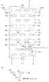
図1は本発明の実施の形態に係るインクジェット方式の画像形成装置の全体構成図である。画像形成装置10は、インクの色(ブラック(K)、シアン(C)、マゼンタ(M)、イエロー(Y))ごとの記録ヘッド12K,12C,12M,12Y(以下、単に記録ヘッド12と記載する場合もある)と、この記録ヘッド12のノズル面14に対向して配置され、記録紙16の平面性を保持しながら記録紙16をベルト17にて搬送するベルト搬送部18と、記録紙16を供給する給紙部20と、画像形成済みの記録紙を外部に排出する排紙部22と、を備えている。排紙部22には画像形成済みの記録紙16を集積する排出トレー23などが設けられている。 FIG. 1 is an overall configuration diagram of an ink jet image forming apparatus according to an embodiment of the present invention. The
記録ヘッド12は、記録紙16の紙幅に対応する長さを有するライン型ヘッドを紙送り方向と直交方向に固定配置した、いわゆるフルライン型ヘッドで構成されている。記録紙16の搬送方向(矢印A)に沿って上流側からブラック(K)、シアン(C)、マゼンタ(M)、イエロー(Y)の順に各色インクに対応した記録ヘッド12が配置されている。 The
なお、本例では、KCMYの標準色(4色)の構成を例示したが、インク色や色数の組み合わせについては本実施形態に限定されず、必要に応じて淡インク、濃インク、特別色インクを追加してもよい。例えば、ライトシアン、ライトマゼンタなどのライト系インクを吐出する印字ヘッドを追加する構成も可能である。また、各色ヘッドの配置順序も特に限定はない。 In this example, the configuration of KCMY standard colors (four colors) is illustrated, but the combination of ink colors and the number of colors is not limited to this embodiment, and light ink, dark ink, and special colors are used as necessary. Ink may be added. For example, it is possible to add a print head that discharges light ink such as light cyan and light magenta. Also, the arrangement order of the color heads is not particularly limited.
各記録ヘッド12の下部にはノズル面14が備えられ、記録紙16を搬送しつつノズル面14に配置されたノズルから各色インクを記録紙16に吐出することにより記録紙16上にカラー画像などを形成する。 A
給紙部20にはロール紙(連続用紙)26が着脱自在にセットされている。給紙部20の一例としてロール紙26が用いられているが、紙幅や紙質等が異なる複数のロール紙をロール紙26と併設した構成としてもよい。また、ロール紙26に代えて、又はこれと併用して、カット紙が積層装填されたカセット26Aによって用紙を供給してもよい。この場合にはカセット26Aからカット紙を搬送供給させる供給ローラ27が設けられる。 Roll paper (continuous paper) 26 is detachably set in the
給紙部20近傍には、ロール紙26から記録紙16を引き出す引き出しローラ21が設けられている。引き出しローラ21の少なくとも一つには後述するモータ25の動力が伝達され、引き出された記録紙16は図1上の右から左へと搬送される。ここで、符号24はローラ21間に設置された裁断用のカッターであり、このカッター24によってロール紙26から引き出された記録紙16は所望のサイズにカットされる。なお、ロール紙26に装填されていたことによる記録紙16の巻きぐせを除去する不図示のデカール処理部をカッター24近傍に配置した構成としてもよい。 In the vicinity of the
ベルト搬送部18は、ローラ30,32,34,36間に無端状のベルト17が巻き掛けられた構造をなし、少なくとも記録ヘッド12のノズル面14に対向する部分が水平面(フラット面)をなすように構成されている。ベルト17が巻かれているローラ30,32,34,36の少なくとも一つには後述するモータ37の動力が伝達され、ベルト17は図1上の反時計回り方向に駆動されて、ベルト17上に吸着された記録紙16は図1の右から左へと搬送される。 The
ローラ30,32,34,36間に掛け渡されたベルト17の内側において、記録ヘッド12に対向する位置には吸引チャンバ40が設けられている。 A
また、符号42は記録紙16の位置および大きさを読み取る記録紙検出部、符号44は記録紙16へのインク吐出タイミング決定用の記録位置検出部、符号46はベルト17の位相を検出する位相検出部、符号48は記録紙16の紙詰まりや次紙の供給タイミング決定用の記録紙終端検出部である。
図2に示すように、記録ヘッド12下部のノズル面14にはノズル群50(50A,50B)が千鳥状に複数配置されている。それぞれのノズル群50は、搬送方向と直交する方向(主走査方向)に一定のピッチ(△t)で直線状に配列されたノズル52からなる。さらに、搬送方向下流側のノズル群50Aと搬送方向上流側のノズル群50Bとでは、搬送方向と直交する方向に対してハーフピッチ(△t/2)だけその位置をずらして配置されている。かかる構造を有する記録ヘッド12によって、ノズル52が全幅領域L1に渡って単一直線状に配列されたものと等価的に取り扱うことができ、高密度のノズル配列を実現できる。なお、記録ヘッド12の別の態様として、図3に示すようにその下部にノズル群50を備えた分割型記録ヘッド53を複数、千鳥状に配置した構成としてもよい。そのような形態とすることによって高密度、高精度のラインヘッドを構成しやすくなる。なお、それぞれの分割型記録ヘッド53は図示しない支持構造にて支持されているものとする。 As shown in FIG. 2, a plurality of nozzle groups 50 (50 </ b> A, 50 </ b> B) are arranged in a staggered manner on the
ここで、用紙(記録紙16)の全幅に対応したノズル列を有するフルラインヘッドで、ノズルを駆動する時には、(1)全ノズルを同時に駆動する、(2)ノズルを片方から他方に向かって順次駆動する、(3)ノズルをブロックに分割して、ブロックごとに片方から他方に向かって順次駆動する、などが行われるが、用紙の幅方向(用紙の搬送方向と直交する方向)に1ライン(1列のドットによるライン又は複数列のドットから成るライン)の画像を形成するようなノズルの駆動を主走査と定義する。 Here, when the nozzles are driven by a full line head having a nozzle row corresponding to the entire width of the paper (recording paper 16), (1) all the nozzles are driven simultaneously, (2) the nozzles are directed from one side to the other. (3) The nozzles are divided into blocks, and the nozzles are sequentially driven from one side to the other for each block, etc., but 1 in the paper width direction (direction perpendicular to the paper conveyance direction). Driving a nozzle that forms an image of a line (a line composed of a single line of dots or a line composed of a plurality of lines of dots) is defined as main scanning.
一方、上述したフルラインヘッドと用紙とを相対移動することによって、上述した主走査で形成された1ライン(1列のドットによるライン又は複数列のドットから成るライン)の印字を繰り返し行うことを副走査と定義する。 On the other hand, by relatively moving the above-mentioned full line head and the paper, printing of one line (a line formed by one line of dots or a line composed of a plurality of lines) formed by the above-described main scanning is repeatedly performed. This is defined as sub-scanning.
そして、上述の主走査によって記録される1ライン(或いは帯状領域の長手方向)の示す方向を主走査方向といい、上述の副走査を行う方向を副走査方向という。すなわち、本実施形態では、記録紙16の搬送方向が副走査方向であり、それに直交する方向が主走査方向ということになる。 The direction indicated by one line (or the longitudinal direction of the belt-like region) recorded by the main scanning is referred to as a main scanning direction, and the direction in which the sub scanning is performed is referred to as a sub scanning direction. In other words, in the present embodiment, the conveyance direction of the
図4(a)に示すようにベルト17は、記録紙16の幅よりも広い幅寸法を有し、ベルト17のベルト面全面には複数の吸引孔56が記録紙16の搬送方向に沿って千鳥状に複数形成されている。それぞれの吸引孔56は記録ヘッド12のノズル群50(図2、図3参照)の配置位置と対向するように配置され、とくに吸引孔56の搬送方向と直交方向の端部58と、これと隣接する吸引孔56の搬送方向と直交方向の端部59とで、それぞれの端部位置が搬送方向に沿ってΔdだけオーバーラップするように形成される。これによって、搬送方向と略直交する方向に吸引孔56を並ぶように投影した際に、記録ヘッド12のノズル全幅領域(図2、図3のL1)に渡って少なくともいずれかの吸引孔56が存在することとなる。なお、吸引孔56の有効幅L2と全幅領域L1とは、L2≧L1の関係を有するが、記録ヘッド12のノズル群50全てに対して回復処理を行なうため、図4(b)に示すようにオーバーラップ部分Δd≧0とすることが必要である。また、吸引孔56の搬送方向における形成間隔は特に限定しないが、記録紙16の搬送方向に沿って配列パターンを一定とするように形成間隔を設定することが好ましい。とくに、後述する記録ヘッドの回復処理時において、搬送される記録紙16の後端と次に搬送される記録紙16の先端との紙間にいずれかの吸引孔56が位置されるよう、図4(a)に示したように吸引孔56をベルト17全面に所定の間隔で形成することが望ましい。 As shown in FIG. 4A, the
図4(a)において、位相検出部46はベルト17両側端部に配置され、ベルト17両側端部に形成されたベルト位相検出用のマーク17A,17Bを検出して吸引孔56の位置を検出する。位相検出部46による吸引孔56の位置検出については後述する。 In FIG. 4A, the
図5において、吸引チャンバ40にはファン60、ノズル回復装置62などが設けられている。ファン60は吸引チャンバ40の床面に取り付けられ、ファン60によって吸引チャンバ40内のエアは吸引チャンバ40外部に排気される。 In FIG. 5, the
ノズル回復装置62は、記録ヘッド12に対向するように配置されたインク受け66および拭取りブレード68と、これらインク受け66および拭取りブレード68を記録ヘッド12に対して進退移動させる昇降装置70、さらにそれぞれの昇降装置70を記録紙16の搬送方向に沿って独立して移動させる移動装置71などから構成される。 The
図6において、インク受け66はその上縁がゴムなどの弾性部材で構成され、前記各ノズル群50を覆うように上部が開放された密着パッド部からなる。インク受け66内部には、多孔質部材からなるインク吸収部材72が設けられている。インク吸収部材72はインク受け66に取り付けられた吸引チューブを介してポンプPと接続されており、ポンプPを駆動させてインク吸収部材72にて吸収されたインクを回収容器74(図5参照)に吸引回収する。なお、ポンプPと回収容器74はインク色毎の記録ヘッド12にそれぞれに設けられているので、回収された色毎のインクを再利用できるほか、吸引を行なわないポンプPの駆動を停止させてポンプの無駄な駆動を防止できる。 In FIG. 6, the
一方、拭取りブレード68はゴムなどの弾性部材にて形成され、昇降軸73を介して昇降装置70に支持されている。昇降装置70は、昇降軸73を上下に移動させて拭取りブレード68を昇降でき、これによって記録ヘッド12下面に接する位置まで拭取りブレード68を進出できる。拭取りブレード68を記録ヘッド12下面に接触させつつ、移動装置71を駆動させて昇降装置70を搬送方向に沿って移動させれば、ノズル52やノズル面14に付着したインク液滴又は異物を拭取りブレード68先端で拭き取り除去できる。なお、この移動に伴って、インク受け66も拭取りブレード68とともに搬送方向に沿って移動される。 On the other hand, the
このような構成の吸引チャンバ40によって、ファン60で吸引して吸引チャンバ40内部を負圧にしつつ、ベルト17を吸引チャンバ40上で駆動させると、ベルト17の吸引孔56を介してエアを吸引チャンバ40内部に吸引できる。したがって、記録紙16が吸引孔56を塞ぐようにベルト17上に配置されると、記録紙16はベルト17に吸着される。なお、これと同時にベルト17における吸引孔56の非形成部分が吸引チャンバ40方向(図5における下方向)に吸引され、ベルト17の記録ヘッド12方向への浮きを防止できるので、記録紙16とノズル52とのクリアランスが一定に維持される。 When the
図7は本発明の画像形成装置10のシステム構成を示す要部ブロック図である。画像形成装置10は通信インターフェース100、システムコントローラ102、プリント制御部110、ヘッドドライバ112、センサ部114、カッター24、ノズル回復装置62などを備えている。 FIG. 7 is a principal block diagram showing the system configuration of the
通信インターフェース100は、ホストコンピュータ120から送られてくる画像データを受信するインターフェース部である。通信インターフェース100にはUSB、IEEE1394、イーサネット(登録商標)、無線ネットワークなどのシリアルインターフェースやセントロニクスなどのパラレルインターフェースを適用できる。ホストコンピュータ120から送出された画像データは通信インターフェース100を介して画像形成装置10に取り込まれ、一旦画像メモリ104に記憶される。画像メモリ104は入力された画像データを一旦格納する記憶手段であり、システムコントローラ102を通じて画像データの読み書きが行われる。The
システムコントローラ102は所定のプログラムに従ってインクジェット記録装置10の全体を制御する制御装置として機能するとともに、各種演算を行う演算装置として機能する。すなわち、システムコントローラ102は、中央演算処理装置(CPU)及びその周辺回路等から構成され、通信インターフェース100、画像メモリ104、モータドライバ106、ファン60等の各部を制御し、ホストコンピュータ86との間の通信制御、画像メモリ74の読み書き制御等を行うとともに、モータ25(37)による記録紙16の搬送や、吸引チャンバ内のファン60などを制御する制御信号を生成する。 The
ROM105には、システムコントローラ102のCPUが実行するプログラム及び制御に必要な各種データなどが格納されている。ROM105は、書換不能な記憶手段であってもよいし、EEPROMのような書換可能な記憶手段であってもよい。画像メモリ104は、画像データの一時記憶領域として利用されるとともに、プログラムの展開領域及びCPUの演算作業領域としても利用される。 The
モータドライバ106は、システムコントローラ102からの指示にしたがってモータ25,37を駆動するドライバ(駆動回路)である。 The
プリント制御部110は、吐出制御部110A、ワイプ制御部110B、キャップ制御部110Cを含んで構成される。吐出制御部110Aは、記録ヘッド12からの吐出動作(予備吐出の動作も含む)を制御するための制御部であり、「吐出制御手段」として機能する。ワイプ制御部110Bは、ノズル回復装置62における拭取りブレード68の動作を制御するための制御部であり、「ワイプ制御手段」として機能する。キャップ制御部110Cは、ノズル回復装置62におけるインク受け66(キャップ部材に相当)の動作(ノズル面に対する進退)を制御するための制御部であり、「キャップ制御手段」として機能する。 The
すなわち、プリント制御部110は、センサ部114からの検出結果をもとに、ヘッドドライバ112、カッター24、ノズル回復装置62などの各部を制御する制御部である。プリント制御部110は、システムコントローラ102の制御に従い、画像メモリ104内の画像データから記録制御用の信号を生成するための各種加工などの処理を行い、生成した記録制御信号(画像形成データ)をヘッドドライバ112に供給する。 That is, the
ヘッドドライバ112はプリント制御部110から与えられる画像形成データに基づいて、記録ヘッド12の各色(K、C、M、Y)の記録ヘッドを駆動する。 The
プリント制御部110に備えられたセンサ部114は、前述した記録紙検出部42、記録位置検出部44、位相検出部46、記録紙終端検出部48(図1参照)を含むブロックであり、これら各検出部によって検出された検出結果はプリント制御部110に提供される。プリント制御部110では、各検出部によって検出された検出結果をもとにプリント制御部110にて所定の演算処理が行なわれ、これら処理結果をシステムコントローラ102に提供する。すなわち、記録紙検出部42における検出結果をもとに、カッター24による記録紙16のカットタイミングなどが決定される。また、記録位置検出部44の検出結果をもとに、インク吐出タイミングなどが決定され、位相検出部46の検出結果をもとに、ベルト17の吸引孔56の位置の検出や、ベルト17への記録紙16の載置位置の決定がなされる。さらに、記録紙終端検出部48による検出結果をもとに、記録紙16の紙詰まり判定や、次紙の供給タイミングなどが決定される。 The sensor unit 114 provided in the
ここで、位相検出部46は図4に示したベルト17両側端部に形成されたベルト位相検出用のマーク17A,17Bを検出する。マーク17Aは吸引孔56の形成位置と同期する位置に位置決めされ、これにより位相検出部46Aによって吸引孔56の位置検出がなされる。また、マーク17Bは、ベルトに対してたとえば1箇所に形成され、位相検出部46Bによってベルト17の一周毎の周期検出がなされる。この位相検出部46と前記記録紙検出部42とによって、搬送される記録紙16および吸引孔56の位置が検出され、後述するノズル回復装置62による記録ヘッド12の回復処理が行なわれる。 Here, the
次に、上記の如く構成された画像形成装置10の作用について説明する。 Next, the operation of the
図7において、印刷すべき画像のデータがホストコンピュータ120から通信インターフェース100を介して入力され、画像メモリ104に蓄えられる。システムコントローラ102はモータドライバ106を介してモータ25(37)を駆動し、図1に示したロール紙26から記録紙16を引き出し、カッター24まで搬送する。システムコントローラ102は、プリント制御部110を介してカッター24に画像データによって予め定められた用紙サイズに記録紙16をカットさせ、カットされた記録紙16はベルト搬送部18へと送られる。次いで、システムコントローラ102は、センサ部114からの検出結果をもとにカットされた記録紙16をベルト17上に載置させるようにモータドライバ106に制御信号を出力する。すなわち、記録紙検出部42および位相検出部46によって記録紙16の位置とベルト17の吸引孔56の位置とがそれぞれ検出され、システムコントローラ102はこの検出結果をもとに、吸引孔56が記録紙16によって覆われる位置となるようにモータドライバ106に指示信号を出力する。モータ25はこれを受けてローラ21を回転制御し、モータ37はローラ30,32,34,36を回転制御する。 In FIG. 7, image data to be printed is input from the
さらに、システムコントローラ102によってファン60が駆動され、ベルト17の吸引孔56からエアが吸引される。ベルト17上の記録紙16は吸引孔56のエア吸引によってベルト17上で吸着されて搬送される。 Further, the fan 60 is driven by the
記録紙16がベルト17によって搬送されて記録ヘッド12に到達すると、記録紙16への画像形成が行われる。すなわち、図7における画像メモリ104に蓄えられた画像データはプリント制御部110に送られ、ヘッドドライバ112を介してインク色ごとのドットのデータに変換される。ヘッドドライバ112はこのドットデータを取り込み、記録ヘッド12の駆動制御信号を生成する。ヘッドドライバ112で生成された駆動制御信号が記録ヘッド12に加えられることによって、ノズル52からインクが記録紙16の記録面に吐出される。なお、記録ヘッド12は、センサ部114の記録位置検出部44からの検出結果をもとに記録紙16の搬送速度に同期して記録ヘッドからのインク吐出タイミングが制御され、記録紙16の搬送を停止させることなく記録紙16上に画像を形成できる。画像記録済みの記録紙16は引き続きベルト17によって搬送され、排紙部22から排出される。 When the
次に、ノズル回復装置62による記録ヘッド12の回復処理について説明する。印字が連続的に行なわれた場合に、使用されないノズルにおける不良インク(未使用による乾燥したインクや粘性が変化したインク)を除去するため、あらかじめ定められた時間または印字回数経過後、以下に示す記録ヘッドの回復処理を行う。 Next, the recovery process of the
所定時間または所定回数に達するまで記録動作が連続的に行われた場合にはプリント制御部110は、搬送される記録紙16の先端を記録紙検出部42によって検知するとともに、吸引孔56の位置を位相検出部46によって検知し、現在搬送中の記録紙16の後端が記録ヘッド12Kを通過した後で、かつ吸引孔56が記録ヘッド12Kと対向する位置となった際に、ヘッドドライバ112を介して記録ヘッド12Kにおけるノズル(吸引孔56の位置と対向するノズル)からインクを予備吐出させる。つまり、記録ヘッド12Kとの対向位置に記録紙16の相互間の隙間(紙間)が位置され、かつ吸引孔56が記録ヘッド12Kと対向した位置となったときに、その紙間の吸引孔56に向けて記録ヘッド12Kのノズルからインクを予備吐出させる。吐出されたインクは、吸引孔56の下方に位置するインク受け66に打滴されて、インク吸収部材72によって吸収される。 When the recording operation is continuously performed until the predetermined time or the predetermined number of times is reached, the
このようにして記録ヘッド12Kの吐出不良回復処理をした後は、同様にして、紙間の吸引孔56が他の記録ヘッド12(12C,12M,12Y)の対向位置に順次ずれることにともない、その紙間の吸引孔56に向ってプリントに寄与しないインクを吐出し、各色の記録ヘッドにて回復処理を行う。したがって、紙間の吸引孔56の位置と同期して予備吐出を行なえるので、画像形成を中断せずに記録ヘッド12の回復処理が行なえる。 After the ejection failure recovery process of the
拭取りブレード68による回復処理は、前述したインク受け66による回復処理と同様に、現在搬送中の記録紙16の後端と、次に搬送される記録紙16の先端との紙間を利用して、吸引孔56が記録ヘッド12と対向する位置となった際に行なわれる。プリント制御部110は昇降装置70を駆動して、吸引孔56を介して拭取りブレード68を記録ヘッド12に対して進出させるとともに、移動装置71を駆動して拭取りブレード68を吸引孔56の搬送速度と同じ速度で移動させて、拭取りブレード68先端をノズル面14に対して摺動させる。これによってノズル52まわりやノズル面14に付着した不良インクなどを除去できる。ノズル52の清掃終了後、昇降装置70の昇降軸73を下降させて記録ヘッド12から拭取りブレード68を退出させる。この後、吸引孔56が他の記録ヘッド12の対向位置に順次ずれることにともない、同様にその吸引孔56を介して、記録ヘッド12の対向位置に配置されたそれぞれの拭取りブレード68によりノズル52を清掃する。なお、各拭取りブレード68は、ノズル52の清掃後には移動装置71によって搬送方向と逆方向に移動されて元の位置(イニシャル位置)まで戻る。このように、紙間の吸引孔56の位置と同期して拭取りブレード68によるノズル52まわりやノズル面14に付着した不良インクなどを除去できるので、画像形成を中断せずに記録ヘッド12の回復処理が行なえる。 The recovery process by the
ノズル52における不良インクの吸引も予備吐出、拭取りと同様にベルト17の吸引孔56を介して同様になされる。昇降装置70を駆動して記録ヘッド12下面と接する位置までインク受け66(インク受け66が吸引キャップとして機能)を進出させ、記録ヘッド12下面にインク受け66を密着させつつポンプPを駆動させてインク受け66内部のエアを吸引すれば、ノズル52内のインク(不良インク)をインク受け66によって吸引除去できる。このとき、位相検出部46でマーク17A,17Bを検出し、吸引孔56がインク受け66と対向する位置となるようにベルト17の駆動を停止させておく。除去されたインクはインク吸収部材72に打滴されて吸収され、吸引チューブを介して回収容器74にて回収される。 The suction of the defective ink at the
なお、インク乾燥防止としての作用を説明すると、非印刷時においては、昇降装置70によってインク受け66を記録ヘッド12の下面に常時密着させて、記録ヘッド12のノズル52(ノズル群50)をインク受け66にて覆う。これによりノズル52の乾燥を防止できるので、ノズル52のインク劣化を防止できるほか、ノズル52へのゴミなどの付着も防止できる。 The operation for preventing ink drying will be described. During non-printing, the
このように、本発明の実施の形態にかかる画像形成装置10によれば、ノズル全てに対して記録ヘッド12を退避させることなく回復処理を行なえる。また、ベルト17に千鳥状に配置された吸引孔56によって、ベルト17の剛性低下を防止できる。さらに、ベルト搬送部18の吸引チャンバ40内部に回復処理のための機器を設置したので、画像形成装置を小型化して設置場所を省スペース化できる。 As described above, according to the
ここで、ノズル回復装置62を搬送方向に沿って独立して移動させる構成としているが、ノズル52と吸引孔56との搬送方向に対するそれぞれの位置を対向させて、ノズル回復装置62を搬送方向に沿って一括駆動する構成としてもよい。また、ノズル回復装置62を移動させる構成としているが、ベルト搬送部18の移動手段を設けて、ベルト搬送部18全体をノズル回復装置62とともに搬送方向に沿って移動させる構成としてもよく、このような構成においても本発明と同様の効果が得られる。 Here, the
さらに、本実施の形態の画像形成装置では、あらかじめ定められた時間または記録回数経過後に記録ヘッドの回復処理を行う構成としたが、これに限ることなく、たとえばインク吐出不良を検出する既存のラインセンサを記録ヘッド12近傍に設け、このラインセンサによって吐出不良が検出された場合に上述した記録ヘッドの回復処理を行う構成としてもよい。この場合には、吸引孔56それぞれにノズル回復装置62を設ける必要は無く、たとえばノズル回復装置62を1ユニットだけ吸引チャンバ40内で搬送方向およびこれと直交する方向に移動可能に設け、吐出不良が検出された記録ヘッドまでノズル回復装置62を移動させて、当該記録ヘッドのみ回復処理を行なう構成としても構わない。とくに、ノズル回復装置62を、記録ヘッド12の対向する位置と待機位置間とで移動可能とすれば、通常の画像形成時にはノズル回復装置62を吸引孔56から退避できる。これにより、画像形成時には吸引孔56の開口スペースを大きく確保できるので、記録紙16の吸着搬送の吸引力を高めて記録紙16の搬送安定性が向上できる。なお、当該退避位置は吸引チャンバ40内部または外部を問わないが、吸引孔56の開口スペースを大きく確保できる位置であればよい。Furthermore, in the image forming apparatus according to the present embodiment, the recording head recovery process is performed after a predetermined time or the number of times of recording. However, the present invention is not limited to this. For example, an existing line for detecting an ink ejection defect is used. A sensor may be provided in the vicinity of the
つぎに、本発明に係る画像形成装置の第2の実施の形態を、図8に示す画像形成装置150を用いて説明する。画像形成装置150は、前述した画像形成装置10のベルト搬送部18とノズル回復装置62の構成を変更したものであり、同一、類似の部材には同一の番号を付してその説明を省略する。 Next, a second embodiment of the image forming apparatus according to the present invention will be described using an
画像形成装置150は、記録ヘッド12と、記録ヘッド12に対向して配置されたベルト搬送部154と、ベルト搬送部154内部に配置されたノズル回復装置156などから構成される。 The
ベルト搬送部154は、ローラ158,160間に静電吸着ベルト162が巻き掛けられた構造をなす。静電吸着ベルト162は、吸着面において静電効果による記録紙16の静電吸着を可能としたものである。また、静電吸着ベルト162には、前記吸引孔56と同構成の開口部163が形成されている。ローラ158,160にはモータ37(図7参照)の動力が伝達され、静電吸着ベルト162は図1上の反時計回り方向に駆動されて、静電吸着ベルト162上に吸着された記録紙16は図8の右から左へと搬送される。 The
ノズル回復装置156は、記録ヘッド12に対向配置されたインク受け66および拭取りブレード68と、これらインク受け66および拭取りブレード68を記録ヘッド12に対して進退移動させる昇降装置70、さらに昇降装置70を記録紙16の搬送方向に沿って移動させる移動装置71などから構成される。 The
昇降装置70を駆動して拭取りブレード68を記録ヘッド12のノズル面14に接触させつつ、移動装置71を吸引孔56と同期して駆動させて昇降装置70を搬送方向に沿って移動させれば、ノズル52や記録ヘッド12下面に付着したインク液滴又は異物を拭取りブレード68先端で拭き取り除去できる。清掃終了後、昇降装置70にて記録ヘッド12から拭取りブレード68を退出させた後、移動装置71によって昇降装置70を搬送方向と逆方向に移動させてイニシャル位置まで戻す。 While the lifting
予備吐出時には、現在搬送中の記録紙16の後端が記録ヘッド12を通過した後で、かつ吸引孔56が記録ヘッド12Kと対向する位置となった際に、ヘッドドライバ112を介して記録ヘッド12における吸引孔56の位置と対向するノズルからインクを吐出させる。 At the time of preliminary ejection, after the rear end of the
さらに、ノズルの吸引も予備吐出、拭取りと同様に静電吸着ベルト162の吸引孔56を介して同様になされ、昇降装置70を駆動して記録ヘッド12下面と接する位置までインク受け66を進出させ、記録ヘッド12下面にインク受け66を密着させつつポンプを駆動させて、ノズル52内の不良インクをによって吸引除去できる。 Further, the suction of the nozzle is similarly performed through the
なお、符号151は静電吸着ベルト162に記録紙16を吸着させるための押圧ローラである。
このように、本発明の実施の形態にかかる画像形成装置150によれば、画像形成を中断することなく回復処理を行なえ、生産性を向上できる。また、ベルトに静電吸着ベルトを用いたので、前記実施の形態で示した吸引チャンバ40を省略できる。 As described above, according to the
なお、同図においては記録ヘッド12は1ユニットのみ記載されているが、インクの色ごとの記録ヘッド12を搬送方向に沿って複数配置してもよい。また、各色インク毎の記録ヘッドを備えた当該画像形成装置150を直列配置して、記録紙16をそれぞれの画像形成装置150に直列搬送させて記録紙16上にカラー画像などを形成させてもよい。 In the figure, only one unit of the
また、前述した画像形成装置10,150では、記録紙16の搬送をベルトにて行う構成としたが、これに限らず、開口部が外周部に形成され、記録紙16を外周面にて搬送可能な回転ドラムを用いてもよい。この場合には、回転ドラム内にノズル回復装置が取り付けられ、回転ドラム外周部に形成された開口部を介してノズル回復装置による記録ヘッドの回復処理が行なわれる。 In the
上述したような実施の形態に示した画像形成装置の構成は、前記実施の形態に限定されるものではない。たとえば、拭取りブレード68はゴムなどの弾性部材にて形成したが、これに限ることなくブラシなどを用いてもよい。また、スポンジなどで構成される多孔質部材を拭取りブレードとして用い、インク液滴又は異物を拭き取り回収する構成としてもよい。 The configuration of the image forming apparatus shown in the embodiment as described above is not limited to the above embodiment. For example, the
また、図2および図3では、記録ヘッド12のノズル群50を千鳥配置した構成としたが、1列にノズルが配列されたラインヘッドであっても、位相検出部46Aでマーク17Aを検出することで、吸引孔56の位置に同期して予備吐出できる。 2 and 3, the
さらに、拭取りブレード68による清掃終了後にノズル52から予備吐出を行なう構成とすれば、拭取りブレード68の清掃によるノズル52の目詰まりを除去できる。 Further, if the preliminary ejection is performed from the
10、150…画像形成装置、12…記録ヘッド、16…記録紙、17…ベルト、17A、17B…マーク、18,154…ベルト搬送部、40…吸引チャンバ、42…記録紙検出部、44…記録位置検出部、46…位相検出部、48…記録紙終端検出部、56…吸引孔、60…ファン、66…インク受け(キャップ)、68…拭取りブレード、70…昇降装置、71…移動装置、102…システムコントローラ、110…プリント制御部、162…静電吸着ベルト、163…開口部 DESCRIPTION OF
Claims (2)
Translated fromJapanese前記記録媒体を支持しつつ搬送して、前記記録ヘッドと前記記録媒体とを相対移動させる記録媒体搬送手段であって、前記記録媒体を支持する媒体支持部の全面には、負圧発生手段による負圧を利用して前記記録媒体を吸着支持する複数の開口部が前記記録媒体の搬送方向に沿って一定の配列パターンで形成され、該複数の開口部を前記記録媒体の搬送方向と略直交する方向に並ぶように投影した際に、前記記録ヘッドのノズル全幅領域に渡って少なくともいずれかの開口部が存在するように、前記複数の開口部が千鳥状に配置された記録媒体搬送手段と、
前記開口部の位置を検出する位相検出手段と、
前記位相検出手段の検出結果に基づき、前記開口部の位置と同期して開口部に向けて前記記録ヘッドからインクを予備吐出させる吐出制御手段と、
当該予備吐出されたインクを、前記開口部を介して回収するためのインク受け部材と前記開口部を介して前記記録ヘッドのノズル面を払拭するワイプ部材と前記ワイプ部材を、前記開口部を通して前記ノズル面に対して進出または退出させる進退移動手段とを備えてなる1ユニットのみのノズル回復装置と、
前記記録ヘッドのノズル面に対して前記ノズル回復装置のワイプ部材を前記搬送方向に摺動させるワイプ部材の摺動手段と、
前記記録ヘッドのノズル面と対向する位置と前記ノズル面と対向しない待機位置とで、前記ノズル回復装置を前記搬送方向および該搬送方向と直交する前記記録媒体の幅方向に移動させる移動手段と、
前記位相検出手段の検出結果に基づき、前記開口部の位置と同期して前記ノズル回復装置のワイプ部材によるワイプ動作を制御するワイプ制御手段と、
を備え、
前記記録媒体搬送手段によって前記記録媒体を搬送しつつ前記記録ヘッドからインクの吐出を行う画像形成時には、前記ノズル回復装置を前記待機位置に退避させ、前記記録ヘッドの回復処理時には、前記ノズル回復装置を前記移動手段によって前記複数の開口部のうちいずれかの開口部の位置で前記ノズル面と対向する位置に移動させ、当該開口部を介して回復処理を実施することを特徴とする画像形成装置。A plurality of line-type recording heads corresponding to each color ink in which a plurality of nozzles for ejecting ink are arranged over a length corresponding to the entire width of the recording medium;
A recording medium conveying unit that conveys the recording medium while supporting the recording medium and relatively moves the recording head and the recording medium. The entire surface of the medium supporting unit that supports the recording medium is provided with a negative pressure generating unit. A plurality of openings for adsorbing and supporting the recording medium using negative pressure are formed in a fixed arrangement pattern along the conveyance direction of the recording medium, and the plurality of openings are substantially orthogonal to the conveyance direction of the recording medium. Recording medium conveying means in which the plurality of openings are arranged in a staggered manner so that at least one of the openings exists across the entire nozzle width region of the recording head when projected so as to line up ,
Phase detection means for detecting the position of the opening;
Discharge control means for preliminarily discharging ink from the recording head toward the opening in synchronization with the position of the opening based on the detection result of the phase detection means;
The preliminary dischargeink, the wiping member and the wiping member that wipes the nozzle surface of the recording head through the opening and the ink receiving member for collecting through theopening, the through the opening A one-unit nozzle recovery device comprising an advancing / retreating means for advancing or retracting the nozzle surface;
A wipe member sliding means for sliding the wipe member of the nozzle recovery device in the transport direction with respect to the nozzle surface of the recording head;
Moving means for moving the nozzle recovery device in the transport direction andthe width direction of therecording medium perpendicular to the transport direction at a position facing the nozzle surface of the recording head and a standby positionnot facing the nozzle surface ;
A wipe control means for controlling a wipe operation by the wipe member of the nozzle recovery device in synchronization with the position of the opening based on the detection result of the phase detection means;
Equipped witha,
The nozzle recovery device is retracted to the standby position at the time of image formation in which ink is ejected from the recording head while the recording medium is conveyed by the recording medium conveying means, and the nozzle recovery device is at the time of recovery processing of the recording head Is moved to a position facing the nozzle surface at the position of any one of the plurality of openings by the moving means, and a recovery process is performed through the opening. .
Priority Applications (1)
| Application Number | Priority Date | Filing Date | Title |
|---|---|---|---|
| JP2004368229AJP3925729B2 (en) | 2003-12-25 | 2004-12-20 | Image forming apparatus |
Applications Claiming Priority (2)
| Application Number | Priority Date | Filing Date | Title |
|---|---|---|---|
| JP2003430547 | 2003-12-25 | ||
| JP2004368229AJP3925729B2 (en) | 2003-12-25 | 2004-12-20 | Image forming apparatus |
Publications (2)
| Publication Number | Publication Date |
|---|---|
| JP2005205901A JP2005205901A (en) | 2005-08-04 |
| JP3925729B2true JP3925729B2 (en) | 2007-06-06 |
Family
ID=34914150
Family Applications (1)
| Application Number | Title | Priority Date | Filing Date |
|---|---|---|---|
| JP2004368229AExpired - Fee RelatedJP3925729B2 (en) | 2003-12-25 | 2004-12-20 | Image forming apparatus |
Country Status (1)
| Country | Link |
|---|---|
| JP (1) | JP3925729B2 (en) |
Families Citing this family (16)
| Publication number | Priority date | Publication date | Assignee | Title |
|---|---|---|---|---|
| JP4951911B2 (en)* | 2005-09-26 | 2012-06-13 | ブラザー工業株式会社 | Transportation method of image recording apparatus |
| JP2007203557A (en)* | 2006-01-31 | 2007-08-16 | Ricoh Co Ltd | Droplet discharge device |
| JP5277853B2 (en)* | 2008-10-14 | 2013-08-28 | 株式会社リコー | Image forming apparatus |
| JP5262635B2 (en)* | 2008-12-01 | 2013-08-14 | セイコーエプソン株式会社 | Fluid ejection device |
| JP5212817B2 (en)* | 2008-12-12 | 2013-06-19 | 株式会社リコー | Image forming apparatus |
| JP5310306B2 (en)* | 2009-06-26 | 2013-10-09 | 株式会社リコー | Image forming apparatus |
| JP5482252B2 (en)* | 2009-09-14 | 2014-05-07 | 株式会社リコー | Image forming apparatus |
| JP5353593B2 (en)* | 2009-09-16 | 2013-11-27 | セイコーエプソン株式会社 | Image forming apparatus and double-sided image forming apparatus |
| JP5459492B2 (en)* | 2010-03-17 | 2014-04-02 | 株式会社リコー | Image forming apparatus |
| JP2013103428A (en)* | 2011-11-15 | 2013-05-30 | Seiko Epson Corp | Continuous sheet for inkjet, and inkjet printer, and preliminary ejection method for inkjet printer |
| US9211736B2 (en)* | 2012-07-25 | 2015-12-15 | Xerox Corporation | System and method for reducing electrostatic fields underneath print heads in an electrostatic media transport |
| FR3044259B1 (en)* | 2015-11-30 | 2018-05-04 | Toutin Service | INK JET PRINTING METHOD, INK JET PRINTING MACHINE, AND ANTI-DRYING DEVICE |
| JP6711019B2 (en)* | 2016-02-29 | 2020-06-17 | セイコーエプソン株式会社 | Conveying device and printing device |
| WO2021246174A1 (en)* | 2020-06-03 | 2021-12-09 | 京セラドキュメントソリューションズ株式会社 | Inkjet recording device |
| JP7543736B2 (en)* | 2020-07-07 | 2024-09-03 | 京セラドキュメントソリューションズ株式会社 | Inkjet recording device |
| JP7677400B2 (en)* | 2021-03-15 | 2025-05-15 | 京セラドキュメントソリューションズ株式会社 | Inkjet recording device |
Family Cites Families (6)
| Publication number | Priority date | Publication date | Assignee | Title |
|---|---|---|---|---|
| US5040000A (en)* | 1988-05-12 | 1991-08-13 | Canon Kabushiki Kaisha | Ink jet recording apparatus having a space saving ink recovery system |
| JP2817964B2 (en)* | 1989-09-05 | 1998-10-30 | キヤノン株式会社 | Liquid jet recording device |
| JPH04197766A (en)* | 1990-11-29 | 1992-07-17 | Canon Inc | inkjet recording device |
| US5717446A (en)* | 1994-12-12 | 1998-02-10 | Xerox Corporation | Liquid ink printer including a vacuum transport system and method of purging ink in the printer |
| JPH10175292A (en)* | 1996-12-19 | 1998-06-30 | Tec Corp | Ink jet printer |
| JP2003341106A (en)* | 2002-05-30 | 2003-12-03 | Konica Minolta Holdings Inc | Image recorder |
- 2004
- 2004-12-20JPJP2004368229Apatent/JP3925729B2/ennot_activeExpired - Fee Related
Also Published As
| Publication number | Publication date |
|---|---|
| JP2005205901A (en) | 2005-08-04 |
Similar Documents
| Publication | Publication Date | Title |
|---|---|---|
| JP3925729B2 (en) | Image forming apparatus | |
| JP4989361B2 (en) | Maintenance device, liquid ejection device, and nozzle surface maintenance method | |
| JP3801604B2 (en) | Droplet discharge apparatus, image forming apparatus, and preliminary discharge method | |
| CN1295081C (en) | Image forming device and recovery jet method for printing head | |
| JP5004280B2 (en) | Cleaning device, liquid ejection device, and liquid ejection surface cleaning method | |
| JP4508131B2 (en) | Inkjet printer | |
| US7334862B2 (en) | Image forming apparatus for performing restoration process | |
| US7467845B2 (en) | Image forming apparatus | |
| US20050052513A1 (en) | Inkjet recording head assembly and inkjet recording apparatus | |
| JP3752692B2 (en) | Image forming apparatus | |
| JP2003127429A (en) | Inkjet printer | |
| JP3909714B2 (en) | Ink jet recording apparatus and preliminary discharge control method | |
| JP3826943B2 (en) | Ink jet head and cleaning method thereof | |
| JP3801603B2 (en) | Image forming apparatus | |
| JP3823991B2 (en) | Ink jet recording apparatus and preliminary discharge control method | |
| JP2006175883A (en) | Image forming apparatus | |
| JP3835468B2 (en) | Image forming apparatus | |
| JP5153024B2 (en) | Liquid ejection device | |
| JP2006123203A (en) | Inkjet recorder | |
| JP2005349798A (en) | Liquid discharging device and image forming device with liquid discharging device | |
| JP3864421B2 (en) | Image forming apparatus | |
| EP3056346B1 (en) | Printing apparatus and method of cleaning printing apparatus | |
| US11945237B2 (en) | Inkjet recording device | |
| JP2006103275A (en) | Ink-jet recording head and recording device | |
| JP2010069837A (en) | Droplet jetting device, image formation device, and method of cleaning droplet jetting head |
Legal Events
| Date | Code | Title | Description |
|---|---|---|---|
| A621 | Written request for application examination | Free format text:JAPANESE INTERMEDIATE CODE: A621 Effective date:20051121 | |
| A871 | Explanation of circumstances concerning accelerated examination | Free format text:JAPANESE INTERMEDIATE CODE: A871 Effective date:20060228 | |
| A975 | Report on accelerated examination | Free format text:JAPANESE INTERMEDIATE CODE: A971005 Effective date:20060316 | |
| A977 | Report on retrieval | Free format text:JAPANESE INTERMEDIATE CODE: A971007 Effective date:20060411 | |
| A131 | Notification of reasons for refusal | Free format text:JAPANESE INTERMEDIATE CODE: A131 Effective date:20060620 | |
| A521 | Written amendment | Free format text:JAPANESE INTERMEDIATE CODE: A523 Effective date:20060815 | |
| A131 | Notification of reasons for refusal | Free format text:JAPANESE INTERMEDIATE CODE: A131 Effective date:20061120 | |
| A521 | Written amendment | Free format text:JAPANESE INTERMEDIATE CODE: A523 Effective date:20070116 | |
| A711 | Notification of change in applicant | Free format text:JAPANESE INTERMEDIATE CODE: A712 Effective date:20070116 | |
| TRDD | Decision of grant or rejection written | ||
| A01 | Written decision to grant a patent or to grant a registration (utility model) | Free format text:JAPANESE INTERMEDIATE CODE: A01 Effective date:20070208 | |
| A61 | First payment of annual fees (during grant procedure) | Free format text:JAPANESE INTERMEDIATE CODE: A61 Effective date:20070221 | |
| R150 | Certificate of patent or registration of utility model | Free format text:JAPANESE INTERMEDIATE CODE: R150 | |
| FPAY | Renewal fee payment (event date is renewal date of database) | Free format text:PAYMENT UNTIL: 20100309 Year of fee payment:3 | |
| FPAY | Renewal fee payment (event date is renewal date of database) | Free format text:PAYMENT UNTIL: 20110309 Year of fee payment:4 | |
| FPAY | Renewal fee payment (event date is renewal date of database) | Free format text:PAYMENT UNTIL: 20110309 Year of fee payment:4 | |
| FPAY | Renewal fee payment (event date is renewal date of database) | Free format text:PAYMENT UNTIL: 20120309 Year of fee payment:5 | |
| FPAY | Renewal fee payment (event date is renewal date of database) | Free format text:PAYMENT UNTIL: 20120309 Year of fee payment:5 | |
| FPAY | Renewal fee payment (event date is renewal date of database) | Free format text:PAYMENT UNTIL: 20130309 Year of fee payment:6 | |
| FPAY | Renewal fee payment (event date is renewal date of database) | Free format text:PAYMENT UNTIL: 20130309 Year of fee payment:6 | |
| FPAY | Renewal fee payment (event date is renewal date of database) | Free format text:PAYMENT UNTIL: 20140309 Year of fee payment:7 | |
| LAPS | Cancellation because of no payment of annual fees |