JP3925485B2 - NOx emission estimation method for internal combustion engine - Google Patents
NOx emission estimation method for internal combustion engineDownload PDFInfo
- Publication number
- JP3925485B2 JP3925485B2JP2003376456AJP2003376456AJP3925485B2JP 3925485 B2JP3925485 B2JP 3925485B2JP 2003376456 AJP2003376456 AJP 2003376456AJP 2003376456 AJP2003376456 AJP 2003376456AJP 3925485 B2JP3925485 B2JP 3925485B2
- Authority
- JP
- Japan
- Prior art keywords
- nox
- amount
- combustion
- region
- internal combustion
- Prior art date
- Legal status (The legal status is an assumption and is not a legal conclusion. Google has not performed a legal analysis and makes no representation as to the accuracy of the status listed.)
- Expired - Fee Related
Links
Images


Classifications
- F—MECHANICAL ENGINEERING; LIGHTING; HEATING; WEAPONS; BLASTING
- F02—COMBUSTION ENGINES; HOT-GAS OR COMBUSTION-PRODUCT ENGINE PLANTS
- F02D—CONTROLLING COMBUSTION ENGINES
- F02D41/00—Electrical control of supply of combustible mixture or its constituents
- F02D41/0025—Controlling engines characterised by use of non-liquid fuels, pluralities of fuels, or non-fuel substances added to the combustible mixtures
- F02D41/0047—Controlling exhaust gas recirculation [EGR]
- F02D41/005—Controlling exhaust gas recirculation [EGR] according to engine operating conditions
- F02D41/0052—Feedback control of engine parameters, e.g. for control of air/fuel ratio or intake air amount
- F—MECHANICAL ENGINEERING; LIGHTING; HEATING; WEAPONS; BLASTING
- F02—COMBUSTION ENGINES; HOT-GAS OR COMBUSTION-PRODUCT ENGINE PLANTS
- F02D—CONTROLLING COMBUSTION ENGINES
- F02D41/00—Electrical control of supply of combustible mixture or its constituents
- F02D41/02—Circuit arrangements for generating control signals
- F02D41/14—Introducing closed-loop corrections
- F02D41/1438—Introducing closed-loop corrections using means for determining characteristics of the combustion gases; Sensors therefor
- F02D41/1444—Introducing closed-loop corrections using means for determining characteristics of the combustion gases; Sensors therefor characterised by the characteristics of the combustion gases
- F02D41/146—Introducing closed-loop corrections using means for determining characteristics of the combustion gases; Sensors therefor characterised by the characteristics of the combustion gases the characteristics being an NOx content or concentration
- F02D41/1461—Introducing closed-loop corrections using means for determining characteristics of the combustion gases; Sensors therefor characterised by the characteristics of the combustion gases the characteristics being an NOx content or concentration of the exhaust gases emitted by the engine
- F02D41/1462—Introducing closed-loop corrections using means for determining characteristics of the combustion gases; Sensors therefor characterised by the characteristics of the combustion gases the characteristics being an NOx content or concentration of the exhaust gases emitted by the engine with determination means using an estimation
- F—MECHANICAL ENGINEERING; LIGHTING; HEATING; WEAPONS; BLASTING
- F02—COMBUSTION ENGINES; HOT-GAS OR COMBUSTION-PRODUCT ENGINE PLANTS
- F02D—CONTROLLING COMBUSTION ENGINES
- F02D41/00—Electrical control of supply of combustible mixture or its constituents
- F02D41/02—Circuit arrangements for generating control signals
- F02D41/14—Introducing closed-loop corrections
- F02D41/1438—Introducing closed-loop corrections using means for determining characteristics of the combustion gases; Sensors therefor
- F02D41/1444—Introducing closed-loop corrections using means for determining characteristics of the combustion gases; Sensors therefor characterised by the characteristics of the combustion gases
- F02D41/146—Introducing closed-loop corrections using means for determining characteristics of the combustion gases; Sensors therefor characterised by the characteristics of the combustion gases the characteristics being an NOx content or concentration
- F02D41/1463—Introducing closed-loop corrections using means for determining characteristics of the combustion gases; Sensors therefor characterised by the characteristics of the combustion gases the characteristics being an NOx content or concentration of the exhaust gases downstream of exhaust gas treatment apparatus
- F02D41/1465—Introducing closed-loop corrections using means for determining characteristics of the combustion gases; Sensors therefor characterised by the characteristics of the combustion gases the characteristics being an NOx content or concentration of the exhaust gases downstream of exhaust gas treatment apparatus with determination means using an estimation
- F—MECHANICAL ENGINEERING; LIGHTING; HEATING; WEAPONS; BLASTING
- F02—COMBUSTION ENGINES; HOT-GAS OR COMBUSTION-PRODUCT ENGINE PLANTS
- F02M—SUPPLYING COMBUSTION ENGINES IN GENERAL WITH COMBUSTIBLE MIXTURES OR CONSTITUENTS THEREOF
- F02M26/00—Engine-pertinent apparatus for adding exhaust gases to combustion-air, main fuel or fuel-air mixture, e.g. by exhaust gas recirculation [EGR] systems
- F02M26/13—Arrangement or layout of EGR passages, e.g. in relation to specific engine parts or for incorporation of accessories
- F02M26/17—Arrangement or layout of EGR passages, e.g. in relation to specific engine parts or for incorporation of accessories in relation to the intake system
- F02M26/21—Arrangement or layout of EGR passages, e.g. in relation to specific engine parts or for incorporation of accessories in relation to the intake system with EGR valves located at or near the connection to the intake system
- F—MECHANICAL ENGINEERING; LIGHTING; HEATING; WEAPONS; BLASTING
- F02—COMBUSTION ENGINES; HOT-GAS OR COMBUSTION-PRODUCT ENGINE PLANTS
- F02M—SUPPLYING COMBUSTION ENGINES IN GENERAL WITH COMBUSTIBLE MIXTURES OR CONSTITUENTS THEREOF
- F02M26/00—Engine-pertinent apparatus for adding exhaust gases to combustion-air, main fuel or fuel-air mixture, e.g. by exhaust gas recirculation [EGR] systems
- F02M26/45—Sensors specially adapted for EGR systems
- F02M26/46—Sensors specially adapted for EGR systems for determining the characteristics of gases, e.g. composition
- F02M26/47—Sensors specially adapted for EGR systems for determining the characteristics of gases, e.g. composition the characteristics being temperatures, pressures or flow rates
- F—MECHANICAL ENGINEERING; LIGHTING; HEATING; WEAPONS; BLASTING
- F02—COMBUSTION ENGINES; HOT-GAS OR COMBUSTION-PRODUCT ENGINE PLANTS
- F02B—INTERNAL-COMBUSTION PISTON ENGINES; COMBUSTION ENGINES IN GENERAL
- F02B2275/00—Other engines, components or details, not provided for in other groups of this subclass
- F02B2275/14—Direct injection into combustion chamber
- F—MECHANICAL ENGINEERING; LIGHTING; HEATING; WEAPONS; BLASTING
- F02—COMBUSTION ENGINES; HOT-GAS OR COMBUSTION-PRODUCT ENGINE PLANTS
- F02B—INTERNAL-COMBUSTION PISTON ENGINES; COMBUSTION ENGINES IN GENERAL
- F02B3/00—Engines characterised by air compression and subsequent fuel addition
- F02B3/06—Engines characterised by air compression and subsequent fuel addition with compression ignition
- F—MECHANICAL ENGINEERING; LIGHTING; HEATING; WEAPONS; BLASTING
- F02—COMBUSTION ENGINES; HOT-GAS OR COMBUSTION-PRODUCT ENGINE PLANTS
- F02D—CONTROLLING COMBUSTION ENGINES
- F02D41/00—Electrical control of supply of combustible mixture or its constituents
- F02D41/02—Circuit arrangements for generating control signals
- F02D41/14—Introducing closed-loop corrections
- F02D41/1438—Introducing closed-loop corrections using means for determining characteristics of the combustion gases; Sensors therefor
- F02D41/1444—Introducing closed-loop corrections using means for determining characteristics of the combustion gases; Sensors therefor characterised by the characteristics of the combustion gases
- F02D41/1454—Introducing closed-loop corrections using means for determining characteristics of the combustion gases; Sensors therefor characterised by the characteristics of the combustion gases the characteristics being an oxygen content or concentration or the air-fuel ratio
- F—MECHANICAL ENGINEERING; LIGHTING; HEATING; WEAPONS; BLASTING
- F02—COMBUSTION ENGINES; HOT-GAS OR COMBUSTION-PRODUCT ENGINE PLANTS
- F02M—SUPPLYING COMBUSTION ENGINES IN GENERAL WITH COMBUSTIBLE MIXTURES OR CONSTITUENTS THEREOF
- F02M26/00—Engine-pertinent apparatus for adding exhaust gases to combustion-air, main fuel or fuel-air mixture, e.g. by exhaust gas recirculation [EGR] systems
- F02M26/02—EGR systems specially adapted for supercharged engines
- F02M26/04—EGR systems specially adapted for supercharged engines with a single turbocharger
- F02M26/05—High pressure loops, i.e. wherein recirculated exhaust gas is taken out from the exhaust system upstream of the turbine and reintroduced into the intake system downstream of the compressor
- F—MECHANICAL ENGINEERING; LIGHTING; HEATING; WEAPONS; BLASTING
- F02—COMBUSTION ENGINES; HOT-GAS OR COMBUSTION-PRODUCT ENGINE PLANTS
- F02M—SUPPLYING COMBUSTION ENGINES IN GENERAL WITH COMBUSTIBLE MIXTURES OR CONSTITUENTS THEREOF
- F02M26/00—Engine-pertinent apparatus for adding exhaust gases to combustion-air, main fuel or fuel-air mixture, e.g. by exhaust gas recirculation [EGR] systems
- F02M26/13—Arrangement or layout of EGR passages, e.g. in relation to specific engine parts or for incorporation of accessories
- F02M26/22—Arrangement or layout of EGR passages, e.g. in relation to specific engine parts or for incorporation of accessories with coolers in the recirculation passage
- F02M26/23—Layout, e.g. schematics
- Y—GENERAL TAGGING OF NEW TECHNOLOGICAL DEVELOPMENTS; GENERAL TAGGING OF CROSS-SECTIONAL TECHNOLOGIES SPANNING OVER SEVERAL SECTIONS OF THE IPC; TECHNICAL SUBJECTS COVERED BY FORMER USPC CROSS-REFERENCE ART COLLECTIONS [XRACs] AND DIGESTS
- Y02—TECHNOLOGIES OR APPLICATIONS FOR MITIGATION OR ADAPTATION AGAINST CLIMATE CHANGE
- Y02T—CLIMATE CHANGE MITIGATION TECHNOLOGIES RELATED TO TRANSPORTATION
- Y02T10/00—Road transport of goods or passengers
- Y02T10/10—Internal combustion engine [ICE] based vehicles
- Y02T10/12—Improving ICE efficiencies
- Y—GENERAL TAGGING OF NEW TECHNOLOGICAL DEVELOPMENTS; GENERAL TAGGING OF CROSS-SECTIONAL TECHNOLOGIES SPANNING OVER SEVERAL SECTIONS OF THE IPC; TECHNICAL SUBJECTS COVERED BY FORMER USPC CROSS-REFERENCE ART COLLECTIONS [XRACs] AND DIGESTS
- Y02—TECHNOLOGIES OR APPLICATIONS FOR MITIGATION OR ADAPTATION AGAINST CLIMATE CHANGE
- Y02T—CLIMATE CHANGE MITIGATION TECHNOLOGIES RELATED TO TRANSPORTATION
- Y02T10/00—Road transport of goods or passengers
- Y02T10/10—Internal combustion engine [ICE] based vehicles
- Y02T10/40—Engine management systems
Landscapes
- Engineering & Computer Science (AREA)
- Chemical & Material Sciences (AREA)
- Combustion & Propulsion (AREA)
- Mechanical Engineering (AREA)
- General Engineering & Computer Science (AREA)
- Analytical Chemistry (AREA)
- Physics & Mathematics (AREA)
- Fluid Mechanics (AREA)
- Combined Controls Of Internal Combustion Engines (AREA)
- Exhaust Gas After Treatment (AREA)
- Electrical Control Of Air Or Fuel Supplied To Internal-Combustion Engine (AREA)
- Exhaust-Gas Circulating Devices (AREA)
Description
Translated fromJapanese本発明は、排気通路を流れる排ガスの一部を吸気通路へ還流せしめるEGR装置を備えた内燃機関に適用され、同排気通路から外部へ排出される排ガス中のNOx量を推定するNOx排出量推定方法に関する。 The present invention is applied to an internal combustion engine including an EGR device that recirculates a part of exhaust gas flowing through an exhaust passage to an intake passage, and estimates NOx emission amount for estimating NOx amount in exhaust gas discharged from the exhaust passage to the outside. Regarding the method.
火花点火式内燃機関、ディーゼル機関等の内燃機関においては、排気通路から外部へ排出される排ガス中のNOx量(以下、「NOx排出量」と云うこともある。)を低減する必要がある。NOx排出量を低減するためには、例えば、EGR装置により還流されるEGRガス量を増大させること、或いは、燃料噴射時期を遅らせること等により最高火炎温度(最高燃焼温度)を低下させることが有効である。 In an internal combustion engine such as a spark ignition internal combustion engine or a diesel engine, it is necessary to reduce the amount of NOx in exhaust gas discharged from the exhaust passage to the outside (hereinafter also referred to as “NOx emission amount”). In order to reduce the NOx emission amount, for example, it is effective to decrease the maximum flame temperature (maximum combustion temperature) by increasing the amount of EGR gas recirculated by the EGR device or delaying the fuel injection timing. It is.
しかしながら、一方では、NOx排出量を低減するためにEGRガス量を増大させていくと(ディーゼル機関において)微粒子状物質(パティキュレート・マター、PM)の排出量が増大していくというトレードオフがあり、また、NOx排出量を低減するために燃料噴射時期を遅らせていくと燃費が悪化していくというトレードオフがあることが知られている。 However, on the other hand, there is a trade-off that if the amount of EGR gas is increased in order to reduce NOx emissions (in diesel engines), the emission of particulate matter (particulate matter, PM) increases. In addition, it is known that there is a trade-off that if the fuel injection timing is delayed in order to reduce the NOx emission amount, the fuel consumption deteriorates.
従って、PM排出量の増大の抑制、燃費の悪化の抑制等を考慮した上でNOx排出量を出来る限り低減するためには、同NOx排出量を機関の運転状態に応じた所定の目標値に制御することが好ましい。NOx排出量を所定の目標値に精度良く制御するためには同NOx排出量を精度良く推定する必要がある。 Therefore, in order to reduce the NOx emission amount as much as possible in consideration of the suppression of the increase in PM emission amount and the deterioration of fuel consumption, the NOx emission amount is set to a predetermined target value corresponding to the operating state of the engine. It is preferable to control. In order to accurately control the NOx emission amount to a predetermined target value, it is necessary to accurately estimate the NOx emission amount.
このため、下記特許文献1に記載の内燃機関の制御装置は、燃焼圧力、及び吸気酸素濃度を、筒内圧力センサ、及び吸気酸素濃度センサによりそれぞれ検出するとともに、これらに基づいて算出した燃焼温度、及び混合気濃度とに基づいて、代表的な公知の燃焼モデルの一つである拡大ゼルドビッチ(ZELDOVICH)機構を用いて燃焼により発生するNOx量(以下、「燃焼発生NOx量」と称呼する。)を推定する。そして、推定された燃焼発生NOx量が所定の燃焼発生NOx量目標値になるようにEGRガス量、或いは燃料噴射時期等を制御することで、NOx排出量を所定の目標値に制御するようになっている。
ところで、EGR装置を備えた内燃機関においては、EGR装置を介してEGRガス中のNOxが燃焼室内に還流してくる。加えて、上記燃焼発生NOx量は、燃焼室の一部であって燃焼が発生する領域(以下、「燃焼領域」と称呼する。)内において発生するNOxの量である。従って、燃焼室内における燃焼領域を除いた領域(以下、「非燃焼領域」と称呼する。)においては燃焼後においても前記還流されてきたNOxが残存しているから、NOx排出量を精度良く推定するためには、上記燃焼発生NOx量のみならず、前記「非燃焼領域内に残存しているNOx量」をも考慮することが必要である。 By the way, in the internal combustion engine provided with the EGR device, NOx in the EGR gas returns to the combustion chamber via the EGR device. In addition, the combustion-generated NOx amount is the amount of NOx generated within a combustion chamber that is a part of the combustion chamber (hereinafter referred to as “combustion region”). Accordingly, in the region excluding the combustion region in the combustion chamber (hereinafter referred to as “non-combustion region”), the NOx that has been recirculated remains after the combustion, and therefore the NOx emission amount can be accurately estimated. In order to achieve this, it is necessary to consider not only the combustion-generated NOx amount but also the “NOx amount remaining in the non-combustion region”.
これに対して、上記従来の装置においては、「非燃焼領域内に残存しているNOx」に対する考慮が全くなされていない。従って、かかる従来の装置をEGR装置を備えた内燃機関に適用した場合、NOx排出量を精度良く推定することができず、この結果、同NOx排出量を所定の目標値に精度良く制御することができないという問題があった。 On the other hand, in the conventional apparatus, no consideration is given to “NOx remaining in the non-combustion region”. Therefore, when such a conventional device is applied to an internal combustion engine equipped with an EGR device, the NOx emission amount cannot be accurately estimated, and as a result, the NOx emission amount is accurately controlled to a predetermined target value. There was a problem that could not.
本発明は、かかる課題に対処するためになされたものであって、その目的は、EGR装置を備えた内燃機関に適用されるNOx排出量推定方法であって、非燃焼領域内に残存しているNOx量を考慮して排気通路から外部へ排出されるNOx排出量を精度良く推定することができるものを提供することにある。 The present invention has been made to cope with such a problem, and an object of the present invention is a NOx emission estimation method applied to an internal combustion engine equipped with an EGR device, which remains in a non-combustion region. An object of the present invention is to provide a device that can accurately estimate the amount of NOx discharged from the exhaust passage to the outside in consideration of the amount of NOx that is present.
本発明による内燃機関のNOx排出量推定方法は、EGR装置を備えた内燃機関に適用され、燃焼室内における燃焼により発生するNOx量(即ち、上記燃焼発生NOx量)と、前記EGR装置を介して前記燃焼室内に還流してきたNOx量とを利用して、機関の排気通路から外部へ排出される排ガス中のNOx量(即ち、上記NOx排出量)を推定する方法である。 The internal combustion engine NOx emission amount estimation method according to the present invention is applied to an internal combustion engine equipped with an EGR device. The NOx amount generated by combustion in the combustion chamber (that is, the combustion-generated NOx amount) and the EGR device are used. This is a method for estimating the amount of NOx in exhaust gas discharged from the exhaust passage of the engine to the outside (that is, the amount of NOx discharged) using the amount of NOx that has recirculated into the combustion chamber.
本発明によるより具体的なNOx排出量推定方法は、EGR装置を備えた内燃機関に適用され、燃焼室内において燃焼が発生する領域である燃焼領域を推定するとともに、前記燃焼領域内にて燃焼により発生する燃焼発生NOx量と、前記燃焼室内における前記燃焼領域を除いた領域である非燃焼領域内におけるNOx量とを推定し、前記燃焼発生NOx量と、前記非燃焼領域内におけるNOx量とに基づいて、前記排気通路から外部へ排出される排ガス中のNOx量を推定する方法である。A more specific NOx emission estimation method according to the present invention is applied to an internal combustion engine equipped with an EGR device, estimates a combustion region in which combustion occurs in a combustion chamber, and performs combustion in the combustion region. The amount of combustion generated NOx and the amount of NOx in the non-combustion region that is the region excluding the combustion region in the combustion chamber are estimated, and the amount of combustion generated NOx and the amount of NOx in the non-combustion region are estimated. Based on this, the amount of NOx in the exhaust gas discharged from the exhaust passage to the outside is estimated.
EGR装置を介して燃焼室内に還流してきたNOx量(の一部)は、燃焼後において上述した「非燃焼領域内に残存しているNOx量」となり得る。従って、これによれば、上記燃焼発生NOx量のみならず、「非燃焼領域内に残存しているNOx量」が考慮されてNOx排出量が推定され得る。The (a part of) NOx amount returned to the combustion chamber via the EGR device can be the “NOx amount remaining in the non-combustion region” described above after combustion. Therefore, according to this, not only the combustion-generated NOx amount but also the “NOx amount remaining in the non-combustion region” can be considered and the NOx emission amount can be estimated.
即ち、推定された燃焼領域内にて燃焼により発生する上記燃焼発生NOx量のみならず、(燃焼後における)非燃焼領域内におけるNOx量、従って、上述した「非燃焼領域内に残存しているNOx量」が考慮されてNOx排出量が推定され得る。従って、NOx排出量を精度良く推定することができる。That is, not only the above-mentioned combustion-generated NOx amount generated by combustion in the estimated combustion region, but also the NOx amount in the non-combustion region (after combustion), and thus the “remaining in the non-combustion region” described above. The NOx emission amount can be estimated in consideration of the “NOx amount”. Therefore, the NOx emission amount can be estimated with high accuracy.
この場合、前記非燃焼領域内におけるNOx量を推定するにあたり、前記EGR装置を介して燃焼室内に還流してきたNOx量のうち燃焼前に前記非燃焼領域内に存在する非燃焼領域還流NOx量を、同非燃焼領域内におけるNOx量として推定することが好適である。 In this case, in estimating the amount of NOx in the non-combustion region, the amount of non-combustion region recirculation NOx existing in the non-combustion region before combustion out of the amount of NOx recirculated into the combustion chamber via the EGR device is calculated. It is preferable to estimate the amount of NOx in the non-combustion region.
燃焼室内における燃焼は燃焼領域内でのみ発生し、非燃焼領域では燃焼が発生しないことから、EGR装置を介して燃焼室内に還流してきたNOx量のうち燃焼前(燃焼開始前)に同非燃焼領域内に存在する非燃焼領域還流NOx量は、燃焼後においてもそのまま保存(保持)され得ると考えることができる。換言すれば、非燃焼領域還流NOx量は、そのまま上述した「非燃焼領域内に残存しているNOx量」となり得る。従って、上記のように構成すれば、簡易な構成(燃焼モデル)で、且つ精度良く「非燃焼領域内に残存しているNOx量」を推定することができ、この結果、簡易な計算でNOx排出量を正確に推定することができる。 Combustion in the combustion chamber occurs only in the combustion region and does not occur in the non-combustion region. Therefore, the non-combustion before the combustion (before the start of combustion) of the NOx amount recirculated into the combustion chamber through the EGR device. It can be considered that the non-combustion region reflux NOx amount existing in the region can be stored (held) as it is even after the combustion. In other words, the non-combustion region recirculation NOx amount can be the “NOx amount remaining in the non-combustion region” as it is. Therefore, if configured as described above, the “NOx amount remaining in the non-combustion region” can be accurately estimated with a simple configuration (combustion model), and as a result, NOx can be calculated by simple calculation. Emissions can be estimated accurately.
更には、前記燃焼発生NOx量を推定するにあたり、前記EGR装置を介して前記燃焼室内に還流してきたNOx量のうち燃焼前に前記燃焼領域内に存在する燃焼領域還流NOx量と、(燃焼後に発生する)前記燃焼発生NOx量のうち大きい方を(燃焼後に燃焼領域内に残存しているNOx量としての)同燃焼発生NOx量として推定することが好適である。 Further, in estimating the combustion-generated NOx amount, among the NOx amount recirculated into the combustion chamber via the EGR device, the combustion region recirculation NOx amount existing in the combustion region before combustion (after combustion) It is preferable to estimate the larger one of the combustion-generated NOx amounts (as generated) as the amount of NOx generated (as the amount of NOx remaining in the combustion region after combustion).
燃焼領域では、燃焼開始前においてはEGR装置を介して前記燃焼室内に還流してきたNOx(従って、前記燃焼領域還流NOx量)が存在する一方で、燃焼後においては燃焼により燃焼発生NOx量が発生する。ここで、一般に、窒素分子N2とNOx(特に、一酸化炭素NO)とは可逆反応により互いに生成され合う物質であって、化学反応後のガス中のNOx量(NOx濃度)は、同化学反応前のNOx量(NOx濃度)にかかわらず、同化学反応後のガスの温度に応じて(ガス温度が高くなるほど大きくなるように)、化学平衡により逐次決定されていく値である。In the combustion region, NOx that has recirculated into the combustion chamber via the EGR device before the start of combustion (and therefore the combustion region recirculation NOx amount) exists, and after combustion, a combustion-generated NOx amount is generated by combustion. To do. Here, in general, nitrogen molecules N2 and NOx (particularly, carbon monoxide) are substances that are mutually generated by a reversible reaction, and the amount of NOx (NOx concentration) in the gas after the chemical reaction is Regardless of the amount of NOx (NOx concentration) before the reaction, the value is sequentially determined by the chemical equilibrium according to the temperature of the gas after the chemical reaction (so that it increases as the gas temperature increases).
また、通常の機関の運転状態では、燃焼により高温となったガス中で発生する上記燃焼発生NOx量の方が上記燃焼領域還流NOx量よりも著しく大きくなる場合が多い。従って、原則的には、燃焼により発生した燃焼発生NOx量が、そのまま(燃焼後に燃焼領域内に残存しているNOx量としての)燃焼発生NOx量に略一致し得ると考えることができる。 Further, in a normal engine operation state, the combustion-generated NOx amount generated in the gas heated to high temperature is often significantly larger than the combustion region recirculation NOx amount. Therefore, in principle, it can be considered that the amount of combustion-generated NOx generated by combustion can substantially match the amount of combustion-generated NOx as it is (as the amount of NOx remaining in the combustion region after combustion).
しかしながら、例えば、EGRガス中のNOx濃度が非常に高く、且つ、アクセル開度が非常に小さくて燃料噴射量が非常に少ないような場合、上記燃焼領域還流NOx量が大きくなる一方で、燃焼によるガス温度の上昇が小さいことに起因して上記燃焼発生NOx量が小さくなる。この結果、燃焼領域還流NOx量の方が燃焼発生NOx量よりも大きくなることがある。このような場合、燃焼発生NOx量よりも燃焼領域還流NOx量の方が、(燃焼後に燃焼領域内に残存しているNOx量としての)燃焼発生NOx量をより正確に表す値になり得ると考えられる。 However, for example, when the NOx concentration in the EGR gas is very high, the accelerator opening is very small, and the fuel injection amount is very small, the combustion region recirculation NOx amount becomes large, but due to combustion The combustion-generated NOx amount is reduced due to the small increase in gas temperature. As a result, the combustion region recirculation NOx amount may be larger than the combustion generated NOx amount. In such a case, the combustion region recirculation NOx amount can be a value that more accurately represents the combustion generation NOx amount (as the NOx amount remaining in the combustion region after combustion) than the combustion generation NOx amount. Conceivable.
換言すれば、上記燃焼領域還流NOx量と、(燃焼後に発生する)前記燃焼発生NOx量のうち大きい方を(燃焼後に燃焼領域内に残存しているNOx量としての)燃焼発生NOx量として推定することが好ましい。従って、上記のように構成すれば、簡易な構成(燃焼モデル)で、且つ精度良く、(燃焼後に燃焼領域内に残存しているNOx量としての)燃焼発生NOx量を推定することができ、この結果、簡易な計算でNOx排出量を正確に推定することができる。 In other words, the larger one of the combustion region recirculation NOx amount and the combustion generation NOx amount (generated after combustion) is estimated as the combustion generation NOx amount (as the NOx amount remaining in the combustion region after combustion). It is preferable to do. Therefore, if configured as described above, the amount of combustion-generated NOx (as the amount of NOx remaining in the combustion region after combustion) can be estimated with a simple configuration (combustion model) and with high accuracy, As a result, the NOx emission amount can be accurately estimated by simple calculation.
上記本発明による何れかのNOx排出量推定方法においては、前記NOx排出量を推定するにあたり、前記燃焼発生NOx量と前記非燃焼領域内におけるNOx量とに基づいて排ガス中のNOx濃度を推定するとともに、同NOx濃度に前記排気通路から外部へ排出される排ガス量を乗じた値を同NOx排出量として推定することが好適である。 In any of the NOx emission amount estimation methods according to the present invention, the NOx concentration in the exhaust gas is estimated based on the combustion-generated NOx amount and the NOx amount in the non-combustion region in estimating the NOx emission amount. At the same time, it is preferable to estimate a value obtained by multiplying the NOx concentration by the amount of exhaust gas discharged from the exhaust passage to the outside as the NOx emission amount.
機関の排気弁から排気通路に排出される際の排ガス中のNOx濃度は、燃焼室内の総ガス量に対する、「上記燃焼発生NOx量と上記非燃焼領域内におけるNOx量の和」の割合として容易に計算することができる。また、排気通路を流れる排ガス中のNOx濃度は同排気通路全域に渡って一定であると仮定すると、機関の排気弁から排気通路に排出される際の排ガス中のNOx濃度は、同排気通路から外部に排出される際の排ガス中のNOx濃度と等しくなる。 The NOx concentration in the exhaust gas when exhausted from the engine exhaust valve to the exhaust passage is easy as the ratio of “the sum of the NOx amount generated in the combustion and the NOx amount in the non-combustion region” to the total gas amount in the combustion chamber. Can be calculated. Assuming that the NOx concentration in the exhaust gas flowing through the exhaust passage is constant over the entire exhaust passage, the NOx concentration in the exhaust gas when exhausted from the engine exhaust valve to the exhaust passage is from the exhaust passage. It becomes equal to the NOx concentration in the exhaust gas when discharged to the outside.
従って、上記のように、燃焼発生NOx量と非燃焼領域内におけるNOx量とに基づいて計算され得る(機関の排気弁から排気通路に排出される際の)排ガス中のNOx濃度に排気通路から外部へ排出される排ガス量を乗じることで、同排気通路から外部へ排出されるNOx量であるNOx排出量を簡易、且つ精度良く推定することができる。 Therefore, as described above, the NOx concentration in the exhaust gas (when exhausted from the engine exhaust valve to the exhaust passage) can be calculated based on the amount of combustion generated NOx and the NOx amount in the non-combustion region. By multiplying the amount of exhaust gas discharged to the outside, it is possible to easily and accurately estimate the NOx emission amount that is the NOx amount discharged to the outside from the exhaust passage.
この場合、前記吸気通路に吸入される新気量(以下、「吸入新気量」と云うこともある。)を前記排気通路から外部へ排出される排ガス量として推定することが好適である。一般に、内燃機関の吸気通路には同吸気通路に吸入される新気量を計測するためのエアフローメータ等の吸入新気量計測装置が備えられている。また、通常の機関の運転状態(特に、定常運転状態)においては、排気通路から外部へ排出される排ガス量は吸入新気量と略等しくなる。 In this case, it is preferable to estimate the amount of fresh air sucked into the intake passage (hereinafter also referred to as “intake fresh air amount”) as the amount of exhaust gas discharged from the exhaust passage to the outside. In general, an intake passage of an internal combustion engine is provided with an intake fresh air amount measuring device such as an air flow meter for measuring the amount of fresh air taken into the intake passage. Further, in the normal engine operation state (particularly in the steady operation state), the amount of exhaust gas discharged from the exhaust passage to the outside is substantially equal to the amount of fresh intake air.
従って、これによれば、排気通路から外部へ排出される排ガス量を計測するための新たな装置を設けることなく、簡易な構成で、且つ正確に、排気通路から外部へ排出される排ガス量を推定することができ、この結果、NOx排出量を簡易な構成で、且つ正確に推定することができる。 Therefore, according to this, the amount of exhaust gas discharged from the exhaust passage to the outside can be accurately measured with a simple configuration without providing a new device for measuring the amount of exhaust gas discharged from the exhaust passage to the outside. As a result, it is possible to accurately estimate the NOx emission amount with a simple configuration.
また、上記本発明による何れかのNOx排出量推定方法においては、前記燃焼領域を推定するにあたり、前記燃焼室内に吸入された酸素量と、燃焼により消費される酸素量とを推定するとともに、前記燃焼室内に吸入された酸素量に対する前記燃焼により消費される酸素量の割合を利用して前記燃焼領域を推定することが好適である。 Further, in any of the NOx emission estimation methods according to the present invention, in estimating the combustion region, the amount of oxygen sucked into the combustion chamber and the amount of oxygen consumed by combustion are estimated, and It is preferable to estimate the combustion region using the ratio of the amount of oxygen consumed by the combustion to the amount of oxygen sucked into the combustion chamber.
ここにおいて、燃焼室内に吸入された酸素量は、例えば、吸気弁から燃焼室に吸入されてくるガス(以下、「吸気」と云うこともある。)中の酸素濃度(吸気酸素濃度)を計測する吸気酸素濃度センサにより計測される同吸気酸素濃度に、吸入された燃焼室内の総ガス量(以下、「筒内総ガス量」と云うこともある。)を乗じた値として求めることができる。また、燃焼により消費される酸素量は、例えば、噴射された燃料の総てが理論空燃比をもって完全燃焼すると仮定することで求めることができる。 Here, the amount of oxygen sucked into the combustion chamber is measured, for example, by measuring the oxygen concentration (intake oxygen concentration) in the gas sucked into the combustion chamber from the intake valve (hereinafter also referred to as “intake”). It can be obtained as a value obtained by multiplying the intake oxygen concentration measured by the intake oxygen concentration sensor to be multiplied by the total amount of gas in the intake combustion chamber (hereinafter sometimes referred to as “in-cylinder total gas amount”). . Further, the amount of oxygen consumed by combustion can be determined, for example, by assuming that all of the injected fuel is completely burned with the stoichiometric air-fuel ratio.
燃焼室内に吸入された吸気中の酸素分子、NOxを含む各ガスの成分は同燃焼室内全域に渡ってそれぞれ均一に分布すると仮定すると、「燃焼室内に吸入された酸素量」に対する「燃焼により消費される酸素量」の割合(以下、「酸素量割合」と称呼する。)は、燃焼室の体積に対する燃焼領域の体積の割合、従って、燃焼室内に吸入された(EGR装置を介して還流してきた)全NOx量に対する、燃焼前に燃焼領域に存在するNOx量の割合を精度良く表す値となり得る。 Assuming that the components of each gas including oxygen molecules and NOx in the intake air sucked into the combustion chamber are uniformly distributed over the entire combustion chamber, the “consumption by combustion” against the “amount of oxygen sucked into the combustion chamber” The ratio of the "amount of oxygen" (hereinafter referred to as the "oxygen amount ratio") is the ratio of the volume of the combustion area to the volume of the combustion chamber, and thus is sucked into the combustion chamber (recirculated through the EGR device). It can be a value that accurately represents the ratio of the NOx amount existing in the combustion region before combustion to the total NOx amount.
従って、上記酸素量割合を利用して前記燃焼領域を推定するように構成すれば、前記燃焼室内に還流してきたNOx量のうち燃焼前に燃焼領域内に存在する燃焼領域還流NOx量、及び、燃焼前に非燃焼領域内に存在する非燃焼領域還流NOx量をより一層精度良く求めることができる。 Therefore, if the combustion region is estimated using the oxygen amount ratio, the combustion region recirculation NOx amount existing in the combustion region before combustion out of the NOx amount recirculated into the combustion chamber, and The amount of non-combustion region recirculation NOx existing in the non-combustion region before combustion can be determined with higher accuracy.
また、上記本発明による何れかのNOx排出量推定方法において、前記内燃機関が一作動サイクル中において少なくとも1回燃料をパイロット噴射した後に同燃料をメイン噴射するように構成されている場合、(メイン噴射による燃料の燃焼終了後において発生している)前記燃焼発生NOx量を推定するにあたり、前記パイロット噴射により発生する不活性ガスの影響を更に考慮して同燃焼発生NOx量を推定することが好適である。 Further, in any one of the NOx emission estimation methods according to the present invention, when the internal combustion engine is configured to perform main injection of the fuel after pilot injection of the fuel at least once in one operation cycle, (main In estimating the combustion-generated NOx amount (generated after completion of fuel combustion by injection), it is preferable to further estimate the combustion-generated NOx amount in consideration of the influence of the inert gas generated by the pilot injection. It is.
1回、或いは複数回のパイロット噴射を行った後にメイン噴射を行う場合、メイン噴射による燃料が燃焼領域において燃焼を開始する時点において、パイロット噴射による燃料の燃焼により発生した不活性ガスが同燃焼領域内に残存していて、この結果、同燃焼領域内の酸素濃度が低下する。また、上記燃焼領域内に残存している不活性ガスの熱容量によりメイン噴射による燃料の最高燃焼温度が低下する。 When the main injection is performed after one or a plurality of pilot injections, the inert gas generated by the combustion of the fuel by the pilot injection is in the same combustion region when the fuel by the main injection starts to burn in the combustion region. As a result, the oxygen concentration in the combustion region decreases. Moreover, the maximum combustion temperature of the fuel by main injection falls with the heat capacity of the inert gas which remains in the said combustion area.
以上のことから、燃焼領域内において燃焼により発生する燃焼発生NOx量は、内燃機関が一作動サイクル中において、1回で必要な量の燃料を噴射するように構成されている場合よりも、パイロット噴射とメイン噴射とに分けて同量の燃料を噴射する場合の方が小さくなる。 From the above, the amount of combustion-generated NOx generated by combustion in the combustion region is more pilot than in the case where the internal combustion engine is configured to inject a necessary amount of fuel at one time in one operation cycle. The case where the same amount of fuel is injected separately into the injection and the main injection is smaller.
従って、上記のように、少なくとも1回のパイロット噴射を行った後にメイン噴射を行う場合、パイロット噴射により発生する不活性ガスの影響を更に考慮して燃焼発生NOx量を推定するように構成すれば、同不活性ガスの影響による燃焼発生NOx量の低下を考慮することで同燃焼発生NOx量をより一層精度良く推定することができる。ここで、不活性ガスの影響による燃焼発生NOx量の低下量は、例えば、パイロット噴射による燃料噴射量、或いは、同パイロット噴射の時期等の関数として計算することができる。 Accordingly, as described above, when the main injection is performed after at least one pilot injection, the combustion generated NOx amount is estimated by further considering the influence of the inert gas generated by the pilot injection. Considering the decrease in the amount of combustion-generated NOx due to the influence of the inert gas, the amount of combustion-generated NOx can be estimated with higher accuracy. Here, the amount of decrease in the combustion-generated NOx amount due to the influence of the inert gas can be calculated, for example, as a function of the fuel injection amount by pilot injection or the timing of the pilot injection.
以下、本発明の実施形態に係る内燃機関のNOx排出量推定方法を実施する内燃機関(ディーゼル機関)の制御装置について図面を参照しつつ説明する。 A control device for an internal combustion engine (diesel engine) that implements the NOx emission estimation method for an internal combustion engine according to an embodiment of the present invention will be described below with reference to the drawings.
図1は、係る内燃機関の制御装置を4気筒内燃機関(ディーゼル機関)10に適用したシステム全体の概略構成を示している。このシステムは、燃料供給系統を含むエンジン本体20、エンジン本体20の各気筒の燃焼室(筒内)にガスを導入するための吸気系統30、エンジン本体20からの排ガスを放出するための排気系統40、排気還流を行うためのEGR装置50、及び電気制御装置60を含んでいる。 FIG. 1 shows a schematic configuration of a whole system in which the control device for an internal combustion engine is applied to a four-cylinder internal combustion engine (diesel engine) 10. This system includes an engine
エンジン本体20の各気筒の上部には燃料噴射弁(噴射弁、インジェクタ)21が配設されている。各燃料噴射弁21は、図示しない燃料タンクと接続された燃料噴射用ポンプ22に燃料配管23を介して接続されている。燃料噴射用ポンプ22は、電気制御装置60と電気的に接続されていて、同電気制御装置60からの駆動信号(後述する基本燃料噴射圧力Pcrbaseに応じた指令信号)により燃料の実際の噴射圧力(吐出圧力)が同基本燃料噴射圧力Pcrbaseになるように同燃料を昇圧するようになっている。 A fuel injection valve (injection valve, injector) 21 is disposed above each cylinder of the
これにより、燃料噴射弁21には、燃料噴射用ポンプ22から前記基本燃料噴射圧力Pcrbaseまで昇圧された燃料が供給されるようになっている。また、燃料噴射弁21は、電気制御装置60と電気的に接続されていて、同電気制御装置60からの駆動信号(後述する燃料噴射量qfinに応じた指令信号)により所定時間だけ開弁し、これにより各気筒の燃焼室内に前記基本燃料噴射圧力Pcrbaseにまで昇圧された燃料を前記燃料噴射量qfinだけ直接噴射するようになっている。 Thereby, the
吸気系統30は、エンジン本体20の各気筒の燃焼室にそれぞれ接続された吸気マニホールド31、吸気マニホールド31の上流側集合部に接続され同吸気マニホールド31とともに吸気通路を構成する吸気管32、吸気管32内に回動可能に保持されたスロットル弁33、電気制御装置60からの駆動信号に応答してスロットル弁33を回転駆動するスロットル弁アクチュエータ33a、スロットル弁33の上流において吸気管32に順に介装されたインタクーラー34と過給機35のコンプレッサ35a、及び吸気管32の先端部に配設されたエアクリーナ36とを含んでいる。 The
排気系統40は、エンジン本体20の各気筒にそれぞれ接続された排気マニホールド41、排気マニホールド41の下流側集合部に接続された排気管42、排気管42に配設された過給機35のタービン35b、及び排気管42に介装されたディーゼルパティキュレートフィルタ(以下、「DPNR」と称呼する。)43を含んでいる。排気マニホールド41及び排気管42は排気通路を構成している。 The
DPNR43は、コージライト等の多孔質材料から形成されたフィルタ43aを備え、通過する排気ガス中のパティキュレートを細孔表面にて捕集するフィルタである。DPNR43は、担体としてのアルミナに、カリウムK,ナトリウムNa,リチウムLi,セシウムCsのようなアルカリ金属、バリウムBa,カルシウムCaのようなアルカリ土類金属、及びランタンLa、イットリウムYのような希土類金属から選ばれた少なくとも一つを白金とともに担持し、NOxを吸収した後に同吸収したNOxを放出して還元する吸蔵還元型NOx触媒としても機能するようになっている。 The
EGR装置50は、排気ガスを還流させる通路(EGR通路)を構成する排気還流管51と、排気還流管51に介装されたEGR制御弁52と、EGRクーラー53とを備えている。排気還流管51はタービン35bの上流側排気通路(排気マニホールド41)とスロットル弁33の下流側吸気通路(吸気マニホールド31)を連通している。EGR制御弁52は電気制御装置60からの駆動信号に応答し、再循環される排気ガス量(排気還流量、EGRガス流量)を変更し得るようになっている。 The
電気制御装置60は、互いにバスで接続されたCPU61、CPU61が実行するプログラム、テーブル(ルックアップテーブル、マップ)、及び定数等を予め記憶したROM62、CPU61が必要に応じてデータを一時的に格納するRAM63、電源が投入された状態でデータを格納するとともに同格納したデータを電源が遮断されている間も保持するバックアップRAM64、並びにADコンバータを含むインターフェース65等からなるマイクロコンピュータである。 The
インターフェース65は、空気流量(新気流量)計測手段であって吸気管32に配置された熱線式エアフローメータ71、スロットル弁33の下流であって排気還流管51が接続された部位よりも下流の吸気通路に設けられた吸気温センサ72、スロットル弁33の下流であって排気還流管51が接続された部位よりも下流の吸気通路に配設された吸気管圧力センサ73、クランクポジションセンサ74、アクセル開度センサ75、及び、スロットル弁33の下流であって排気還流管51が接続された部位よりも下流の吸気通路に設けられた吸気酸素濃度センサ76と接続されていて、これらのセンサからの信号をCPU61に供給するようになっている。また、インターフェース65は、燃料噴射弁21、燃料噴射用ポンプ22、スロットル弁アクチュエータ33a、及びEGR制御弁52と接続されていて、CPU61の指示に応じてこれらに駆動信号を送出するようになっている。 The
熱線式エアフローメータ71は、吸気通路内を通過する吸入空気(新気)の質量流量(単位時間あたりの吸入新気量)を計測し、同質量流量Ga(吸入新気流量Ga)を表す信号を発生するようになっている。吸気温センサ72は、前述した吸気の温度を検出し、同吸気温度Tbを表す信号を発生するようになっている。吸気管圧力センサ73は、吸気の圧力(即ち、吸気管圧力)を検出し、同吸気管圧力Pbを表す信号を発生するようになっている。 The hot-wire
クランクポジションセンサ74は、各気筒の絶対クランク角度を検出し、クランク角度CAを表すとともにエンジン10の回転速度であるエンジン回転速度NEをも表す信号を発生するようになっている。アクセル開度センサ75は、アクセルペダルAPの操作量を検出し、アクセル操作量Accpを表す信号を発生するようになっている。吸気酸素濃度センサ76は、吸気中の酸素濃度(即ち、吸気酸素濃度)を検出し、同吸気酸素濃度RO2_inを表す信号を発生するようになっている。 The crank position sensor 74 detects the absolute crank angle of each cylinder and generates a signal that represents the crank angle CA and also represents the engine rotation speed NE that is the rotation speed of the
(NOx排出量推定方法の概要)
次に、上記のように構成された内燃機関の制御装置(以下、「本装置」と云うこともある。)による本発明の実施形態に係るNOx排出量推定方法の概要について説明する。図2は、機関10の或る一つの気筒のシリンダ内(筒内)に吸気マニホールド31からガス(即ち、吸気)が吸入され、筒内に吸入されたガス(筒内ガス)が排気マニホールド41へ排出される様子を模式的に示した図である。(Outline of NOx emission estimation method)
Next, an outline of the NOx emission amount estimation method according to the embodiment of the present invention by the internal combustion engine control apparatus configured as described above (hereinafter also referred to as “the present apparatus”) will be described. In FIG. 2, gas (that is, intake air) is sucked into the cylinder (cylinder) of one cylinder of the
図2に示したように、吸気(従って、筒内ガス)には、吸気管32の先端部からスロットル弁33を介して吸入された新気と、排気還流管51からEGR制御弁52を介して吸入されたNOxを含むEGRガスが含まれる。吸入される新気量(新気質量)と吸入されるEGRガス量(EGRガス質量)の和に対するEGRガス質量の割合(即ち、EGR率)は、運転状態に応じて電気制御装置60(CPU61)により適宜制御されるスロットル弁33の開度、及びEGR制御弁52の開度に応じて変化する。 As shown in FIG. 2, fresh air sucked from the front end portion of the
吸気(即ち、新気、及びNOxを含むEGRガスから構成されるガス)は、吸気行程において開弁している吸気弁Vinを介してピストンの下降に伴って筒内に吸入されて筒内ガスとなる。筒内ガスは、ピストンが下死点に達した時点(以下、「ATDC-180°」と称呼する。)で吸気弁Vinが閉弁することにより筒内に密閉され、その後の圧縮行程においてピストンの上昇に伴って圧縮される。そして、ピストンが上死点近傍に達っすると(具体的には、後述する最終燃料噴射時期finjfinが到来すると)、本装置は、前記燃料噴射量qfinに応じた所定時間だけ燃料噴射弁21を開弁することで燃料を筒内に直接噴射する。この結果、噴射された燃料は、時間の経過に伴って同筒内ガスと混ざり合いながら混合気となって筒内において拡散していき、所定のタイミングにて自己着火が発生することに起因して燃焼する。 Intake (that is, gas composed of fresh air and EGR gas containing NOx) is sucked into the cylinder as the piston descends via the intake valve Vin opened in the intake stroke, and the cylinder gas It becomes. The in-cylinder gas is sealed in the cylinder by closing the intake valve Vin when the piston reaches bottom dead center (hereinafter referred to as “ATDC-180 °”). Compressed as the rise of. When the piston reaches the vicinity of the top dead center (specifically, when a final fuel injection timing finjfin, which will be described later, arrives), the present apparatus opens the
係る燃焼は、本実施例では、後述するように推定される燃焼領域(以下、「B領域」と云うこともある。図2を参照。)においてのみ発生し、燃焼室内におけるB領域を除いた領域である非燃焼領域(以下、「A領域」と云うこともある。図2を参照。)では発生しないと仮定する。そして、燃焼後に燃焼室内に存在する筒内ガスは、排ガスとなって、排気行程において開弁している排気弁Voutを介してピストンの上昇に伴って排気マニホールド41へ排出され、係る排ガスは、排気管42を介して外部へと排出されていく。 In this embodiment, such combustion occurs only in a combustion region estimated as described later (hereinafter also referred to as “B region”, see FIG. 2), and excludes the B region in the combustion chamber. It is assumed that it does not occur in the non-combustion region (hereinafter also referred to as “A region”, see FIG. 2). The in-cylinder gas existing in the combustion chamber after combustion becomes exhaust gas, and is discharged to the
以下、このようなEGR装置50を備えた内燃機関10に適用される、本装置が実施する具体的なNOx排出量推定方法について説明していく。このNOx排出量推定方法では、燃料が噴射される対象となる気筒(以下、「燃料噴射気筒」と称呼する。)について上記最終燃料噴射時期finjfinが到来する毎に、その直後の排気行程において同燃料噴射気筒の排気弁Voutから排気通路を介して外部へ排出されることになる排ガス中のNOxの質量(即ち、NOx排出量。実NOx排出量NOxact。)が推定されていく。 Hereinafter, a specific NOx emission amount estimation method implemented by the present apparatus, which is applied to the
この方法では、実NOx排出量NOxactを推定するにあたり、燃焼室内に吸入されたNOxの全質量に対する上記燃焼前に上記B領域に存在するNOxの質量の割合(以下、「NOx量割合RatioNOx」と称呼する。)、上記燃焼後に上記A領域内に残存するNOx質量、及び、上記燃焼後に上記B領域内に残存するNOx質量をそれぞれ推定する必要がある。従って、先ず、これらの求め方について図2を参照しながら説明する。 In this method, in estimating the actual NOx emission amount NOxact, the ratio of the mass of NOx existing in the region B before the combustion to the total mass of NOx sucked into the combustion chamber (hereinafter referred to as “NOx amount ratio RatioNOx”). It is necessary to estimate the NOx mass remaining in the A region after the combustion and the NOx mass remaining in the B region after the combustion. Therefore, first, how to obtain these will be described with reference to FIG.
<NOx量割合RatioNOxの求め方>
燃焼室内に吸入された吸気(筒内ガス)中の酸素分子、NOxを含む各ガスの成分は同燃焼室内全域に渡ってそれぞれ均一に分布するものと仮定する。また、この状態においてB領域内に存在する酸素は総て燃焼により消費されると仮定する。そうすると、「燃焼室内に吸入された酸素の全質量」に対する「燃焼により消費される酸素の質量」の割合(即ち、前記酸素量割合)は、燃焼室の体積に対するB領域の体積の割合を表すとともに、燃焼室内に吸入されたNOxの全質量に対する、燃焼前にB領域に存在するNOxの質量の割合(従って、上記NOx量割合RatioNOx)をも表すことになる。換言すれば、上記酸素量割合を利用してB領域が推定され得る。<How to find the NOx amount ratio RatioNOx>
It is assumed that the components of each gas including oxygen molecules and NOx in the intake air (cylinder gas) sucked into the combustion chamber are uniformly distributed over the entire combustion chamber. In this state, it is assumed that all the oxygen present in the region B is consumed by combustion. Then, the ratio of the “mass of oxygen consumed by combustion” to the “total mass of oxygen sucked into the combustion chamber” (that is, the oxygen amount ratio) represents the ratio of the volume of the region B to the volume of the combustion chamber. In addition, the ratio of the mass of NOx existing in the B region before combustion to the total mass of NOx sucked into the combustion chamber (accordingly, the above-mentioned NOx amount ratio RatioNOx) is also expressed. In other words, the region B can be estimated using the oxygen amount ratio.
従って、NOx量割合RatioNOxを求めるためには上記酸素量割合を求めればよく、このためには、「燃焼室内に吸入された酸素の全質量」と「燃焼により消費される酸素の質量」とを求める必要がある。 Therefore, in order to obtain the NOx amount ratio RatioNOx, the oxygen amount ratio may be obtained. For this purpose, the “total mass of oxygen sucked into the combustion chamber” and “the mass of oxygen consumed by combustion” are determined. Need to ask.
ここで、「燃焼室内に吸入された酸素の全質量」は、吸入された燃焼室内の総ガス質量(以下、「筒内総ガス量Gcyl」と称呼する。)に、燃焼前の筒内ガスの酸素濃度を乗じることで求めることができる。筒内総ガス量Gcylは、ATDC-180°における気体の状態方程式に基づく下記(1)式に従って求めることができる。 Here, the “total mass of oxygen sucked into the combustion chamber” is the total gas mass in the sucked combustion chamber (hereinafter referred to as “total in-cylinder gas amount Gcyl”). It can be obtained by multiplying the oxygen concentration. The in-cylinder total gas amount Gcyl can be obtained according to the following equation (1) based on the equation of state of gas at ATDC-180 °.
Gcyl=(Pa0・Va0)/(R・Ta0) ・・・(1)Gcyl = (Pa0 ・ Va0) / (R ・ Ta0) (1)
上記(1)式において、Pa0は、ATDC-180°における下死点時筒内ガス圧力である。ATDC-180°において筒内ガス圧力は吸気管圧力Pbと略等しいと考えられるから、下死点時筒内ガス圧力Pa0は、ATDC-180°において吸気管圧力センサ73により検出される吸気管圧力Pbとして取得することができる。Va0は、ATDC-180°における下死点時燃焼室内容積である。燃焼室内容積Vaは機関10の設計諸元に基づいてクランク角度CAの関数として表すことができるから、この関数に基づいて下死点時燃焼室内容積Va0も求めることができる。Ta0は、ATDC-180°における下死点時筒内ガス温度である。ATDC-180°において筒内ガス温度は吸気温度Tbと略等しいと考えられるから、下死点時筒内ガス温度Ta0は、ATDC-180°において吸気温センサ72により検出される吸気温度Tbとして取得することができる。Rは筒内ガスのガス定数である。 In the above equation (1), Pa0 is the in-cylinder gas pressure at the bottom dead center at ATDC-180 °. Since the cylinder gas pressure is considered to be substantially equal to the intake pipe pressure Pb at ATDC-180 °, the cylinder gas pressure Pa0 at the bottom dead center is the intake pipe pressure detected by the intake
また、燃焼前の筒内ガスの酸素濃度はATDC-180°における吸気酸素濃度RO2_inと略等しいと考えられるから、燃焼前の筒内ガスの酸素濃度は、ATDC-180°において吸気酸素濃度センサ76により検出される下死点時吸気酸素濃度RO20_inとして取得することができる。以上より、「燃焼室内に吸入された酸素の全質量」は「Gcyl・RO20_in」と表すことができる。 Further, since the oxygen concentration of the in-cylinder gas before combustion is considered to be substantially equal to the intake oxygen concentration RO2_in at ATDC-180 °, the oxygen concentration of the in-cylinder gas before combustion is the intake
一方、「燃焼により消費される酸素の質量」は、噴射された燃料の総て(即ち、前記燃料噴射量qfinの燃料)が理論空燃比stoichをもって完全燃焼するとの仮定のもと、「K・Qfuel」と表すことができる。ここで、Kは所定の係数であって、例えば、大気中に含まれる酸素の質量割合0.23に理論空燃比stoich(例えば、14.6)を乗じた値「0.23・stoich」である。Qfuelは前記燃料噴射量qfinと等しい値である。以上のことから、NOx量割合RatioNOxは、下記(2)式に従って求めることができる。 On the other hand, “the mass of oxygen consumed by combustion” is calculated based on the assumption that all of the injected fuel (that is, the fuel having the fuel injection amount qfin) is completely burned with the stoichiometric air-fuel ratio stoich. Qfuel ”. Here, K is a predetermined coefficient, for example, a value “0.23 · stoich” obtained by multiplying the mass ratio 0.23 of oxygen contained in the atmosphere by the stoichiometric air-fuel ratio stoich (for example, 14.6). is there. Qfuel is a value equal to the fuel injection amount qfin. From the above, the NOx amount ratio RatioNOx can be obtained according to the following equation (2).
RatioNOx=(K・Qfuel)/(Gcyl・RO20_in) ・・・(2)RatioNOx = (K ・ Qfuel) / (Gcyl ・ RO20_in) (2)
<燃焼後にA領域内に残存するNOx質量の求め方>
上述のごとく、本実施例では燃焼室内における燃焼はB領域内でのみ発生し、A領域では燃焼が発生しないと仮定するから、EGR装置50を介して燃焼室内に還流してきたNOx量のうち燃焼前にA領域内に存在するNOxの質量(以下、「A領域還流NOx量NOxA」と称呼する。)は、燃焼後においてもそのままA領域内に保存(保持)されると考えることができる。換言すれば、A領域還流NOx量NOxAは、そのまま「燃焼後にA領域内に残存するNOx質量」となる。<How to determine the NOx mass remaining in the A region after combustion>
As described above, in this embodiment, it is assumed that the combustion in the combustion chamber occurs only in the B region and no combustion occurs in the A region, so the combustion out of the NOx amount returned to the combustion chamber via the
ここで、燃焼室内に吸入されたNOxの全質量に対する上記燃焼前に上記A領域に存在するNOxの質量の割合は、上記NOx量割合RatioNOxを用いて「1-RatioNOx」と表すことができるから、A領域還流NOx量NOxAは、上記筒内総ガス量Gcylに、燃焼前の筒内ガスのNOx濃度と(1-RatioNOx)とを乗じることで求めることができる。燃焼前の筒内ガスのNOx濃度は吸気中のNOx濃度(吸気NOx濃度RNOx_in)と略等しいと考えられるから、A領域還流NOx量NOxAは、下記(3)式にて表すことができる。 Here, the ratio of the mass of NOx existing in the A region before the combustion to the total mass of NOx sucked into the combustion chamber can be expressed as “1-RatioNOx” using the NOx amount ratio RatioNOx. The A region reflux NOx amount NOxA can be obtained by multiplying the in-cylinder total gas amount Gcyl by the NOx concentration of the in-cylinder gas before combustion and (1-RatioNOx). Since the NOx concentration of the in-cylinder gas before combustion is considered to be substantially equal to the NOx concentration in the intake air (intake NOx concentration RNOx_in), the A-region recirculation NOx amount NOxA can be expressed by the following equation (3).
NOxA=RNOx_in・(1-RatioNOx)・Gcyl ・・・(3)NOxA = RNOx_in ・ (1-RatioNOx) ・ Gcyl (3)
上記(3)式において、吸気NOx濃度RNOx_inは、上記筒内総ガス量Gcylに対する、EGR装置50から還流されてきたEGRガス中のNOx質量の質量割合である。EGRガス中のNOx濃度は前回(の燃料噴射時期に)演算された後述する排気NOx濃度RNOx_exと等しいと仮定すると、吸気NOx濃度RNOx_inは下記(4)式に従って求めることができる。 In the above equation (3), the intake NOx concentration RNOx_in is the mass ratio of the NOx mass in the EGR gas recirculated from the
RNOx_in=(RNOx_ex・Gegr)/Gcyl ・・・(4)RNOx_in = (RNOx_ex · Gegr) / Gcyl (4)
上記(4)式において、Gegrは今回の吸気行程で吸気の一部としてEGR装置50から燃焼室内に吸入されてきたEGRガスの質量であって、下記(5)式に従って取得され得る。 In the above equation (4), Gegr is the mass of the EGR gas that has been sucked into the combustion chamber from the
Gegr=Gcyl-Gm ・・・(5)Gegr = Gcyl-Gm (5)
上記(5)式において、Gmは今回の吸気行程で吸気管32の先端部から吸気の一部として燃焼室内に吸入された新気の質量(吸入新気量)であって、エアフローメータ71により計測される単位時間あたりの吸入新気量(吸入新気流量Ga)と、クランクポジションセンサ74の出力に基づくエンジン回転速度NEと、吸入新気流量Ga及びエンジン回転速度NEを引数とする一吸気行程あたりの吸入新気量を求めるための関数f(Ga,NE)とに基づいて計算される。吸入新気流量Ga及びエンジン回転速度NEとしては、ATDC-180°において各センサにより取得される下死点時吸入新気流量Ga0、及び下死点時エンジン回転速度NE0がそれぞれ使用される。以上のように、A領域還流NOx量NOxA、従って、「燃焼後にA領域内に残存するNOx質量」は上記(3)式に従って求めることができる。 In the above equation (5), Gm is the mass of fresh air (amount of fresh intake air) sucked into the combustion chamber as a part of the intake air from the tip of the
<燃焼後にB領域内に残存するNOx質量の求め方>
EGR装置50を介して燃焼室内に還流してきたNOx量のうち燃焼前にB領域内に存在するNOxの質量(以下、「B領域還流NOx量NOxB2」と称呼する。)は、上記(3)式にて表されるA領域還流NOx量NOxAと同様にして、下記(6)式にて表すことができる。<How to determine the NOx mass remaining in the B region after combustion>
Of the amount of NOx recirculated into the combustion chamber via the
NOxB2=RNOx_in・RatioNOx・Gcyl ・・・(6)NOxB2 = RNOx_in ・ RatioNOx ・ Gcyl (6)
一方、燃焼後においてはB領域において燃焼により燃焼発生NOx量(以下、「B領域燃焼発生NOx量NOxB1」と称呼する。)が発生する。B領域燃焼発生NOx量NOxB1は、例えば、単位燃料量あたりの燃焼発生NOx量(以下、「燃焼発生NOx率RNOx_burn」と称呼する。)に上記燃料噴射量Qfuelを乗じた値として、下記(7)式に従って求めることができる。燃焼発生NOx率RNOx_burnは、例えば、上記燃料噴射量Qfuelと、エンジン回転速度NEと、燃料噴射量Qfuel及びエンジン回転速度NEを引数とする燃焼発生NOx率を求めるための関数g(Qfuel,NE)とに基づいて計算される。 On the other hand, after combustion, a combustion-generated NOx amount (hereinafter referred to as “B-region combustion generated NOx amount NOxB1”) is generated by combustion in the B region. The B region combustion generated NOx amount NOxB1 is, for example, a value obtained by multiplying the fuel injection amount Qfuel by the combustion generated NOx amount per unit fuel amount (hereinafter referred to as “combustion generated NOx rate RNOx_burn”) (7 ) Can be obtained according to the equation. The combustion generation NOx rate RNOx_burn is, for example, a function g (Qfuel, NE) for obtaining the combustion injection NOx rate with the fuel injection amount Qfuel, the engine rotation speed NE, and the fuel injection amount Qfuel and the engine rotation speed NE as arguments. And calculated based on
NOxB1=RNOx_burn・Qfuel ・・・(7)NOxB1 = RNOx_burn ・ Qfuel (7)
ここで、先に説明したように、燃焼後のガス中のNOx量(NOx濃度)は、同燃焼前のNOx量(NOx濃度)にかかわらず、同燃焼後のガスの温度に応じて(ガス温度が高くなるほど大きくなるように)、化学平衡により逐次決定されていく値である。 Here, as explained above, the NOx amount (NOx concentration) in the gas after combustion depends on the temperature of the gas after combustion (gas concentration) regardless of the NOx amount (NOx concentration) before combustion. It is a value that is sequentially determined by chemical equilibrium so that it increases as the temperature increases.
従って、通常の機関の運転状態では、燃焼により高温となったガス中で発生する上記B領域燃焼発生NOx量NOxB1の方が上記B領域還流NOx量NOxB2よりも著しく大きくなる場合が多い。よって、原則的に、上記B領域燃焼発生NOx量NOxB1がそのまま「燃焼後にB領域内に残存するNOx質量」に略一致し得ると考えることができる。 Therefore, in the normal engine operating state, the B region combustion generated NOx amount NOxB1 generated in the gas heated to a high temperature by combustion often becomes significantly larger than the B region reflux NOx amount NOxB2. Therefore, in principle, it can be considered that the above-mentioned B region combustion generated NOx amount NOxB1 can substantially match the “NOx mass remaining in the B region after combustion” as it is.
しかしながら、例えば、EGRガス中のNOx濃度(従って、前回の燃料噴射時期に演算された後述する排気NOx濃度RNOx_ex)が非常に高く、且つ、アクセル操作量Accpが非常に小さくて燃料噴射量qfin(=Qfuel)が非常に少ないような場合、上記B領域還流NOx量NOxB2が大きくなる一方で、燃焼によるガス温度の上昇が小さいことに起因して上記B領域燃焼発生NOx量NOxB1が小さくなる。この結果、B領域還流NOx量NOxB2の方がB領域燃焼発生NOx量NOxB1よりも大きくなることがある。このような場合、B領域還流NOx量NOxB2の方がB領域燃焼発生NOx量NOxB1よりも「燃焼後にB領域内に残存するNOx質量」をより正確に表す値になり得ると考えられる。 However, for example, the NOx concentration in the EGR gas (accordingly, the exhaust NOx concentration RNOx_ex described later calculated at the previous fuel injection timing) is very high, the accelerator operation amount Accp is very small, and the fuel injection amount qfin ( = Qfuel) is very small, the B region recirculation NOx amount NOxB2 is increased, while the B region combustion generated NOx amount NOxB1 is decreased due to a small increase in gas temperature due to combustion. As a result, the B region recirculation NOx amount NOxB2 may be larger than the B region combustion generated NOx amount NOxB1. In such a case, it is considered that the B region recirculation NOx amount NOxB2 can be a value that more accurately represents the “NOx mass remaining in the B region after combustion” than the B region combustion generated NOx amount NOxB1.
以上のことから、「燃焼後にB領域内に残存するNOx質量」は、上記(7)式に従って求められるB領域燃焼発生NOx量NOxB1と、上記(6)式に従って求められるB領域還流NOx量NOxB2のうち大きい方の値(B領域最終NOx量NOxB)として求めることができる。 From the above, the “NOx mass remaining in the B region after combustion” is the B region combustion generated NOx amount NOxB1 obtained according to the above equation (7) and the B region reflux NOx amount NOxB2 obtained according to the above equation (6). Can be obtained as the larger value (B region final NOx amount NOxB).
このようにして、「燃焼後にA領域内に残存するNOx質量」であるA領域還流NOx量NOxA、及び、「燃焼後にB領域内に残存するNOx質量」であるB領域最終NOx量NOxBが求められると、燃焼後に燃焼室内に残存するNOxの全質量は「NOxA+NOxB」として求めることができる。また、燃焼後に燃焼室内に残存するガスの全質量は、「Gcyl+Qfuel」と表すことができる。 In this way, the A region recirculation NOx amount NOxA that is “NOx mass remaining in the A region after combustion” and the B region final NOx amount NOxB that is “NOx mass remaining in the B region after combustion” are obtained. Then, the total mass of NOx remaining in the combustion chamber after combustion can be obtained as “NOxA + NOxB”. The total mass of the gas remaining in the combustion chamber after combustion can be expressed as “Gcyl + Qfuel”.
従って、排気行程において燃焼室から排気弁Voutを介して排気通路(排気マニホールド41)に排出される排ガス中のNOx濃度(排気NOx濃度RNOx_ex)は、「燃焼後に燃焼室内に残存するガスの全質量」に対する、「燃焼後に燃焼室内に残存するNOxの全質量」の質量割合であって、下記(8)式に従って求めることができる。 Therefore, the NOx concentration (exhaust NOx concentration RNOx_ex) in the exhaust gas discharged from the combustion chamber to the exhaust passage (exhaust manifold 41) through the exhaust valve Vout in the exhaust stroke is “total mass of gas remaining in the combustion chamber after combustion”. The mass ratio of “the total mass of NOx remaining in the combustion chamber after combustion” can be calculated according to the following equation (8).
RNOx_ex=(NOxA+NOxB)/(Gcyl+Qfuel) ・・・(8)RNOx_ex = (NOxA + NOxB) / (Gcyl + Qfuel) (8)
上記(8)式に従って求められる排気NOx濃度RNOx_exの前回値は、排気通路(排気マニホールド41)を流れる排ガス中のNOx濃度が排気還流管51内を流れるEGRガス中のNOx濃度に等しいとの仮定のもと、前述のごとく、上記吸気NOx濃度RNOx_in(の
今回値)を求める際に上記(4)式にて使用される。The previous value of the exhaust NOx concentration RNOx_ex obtained in accordance with the above equation (8) is assumed that the NOx concentration in the exhaust gas flowing through the exhaust passage (exhaust manifold 41) is equal to the NOx concentration in the EGR gas flowing through the exhaust
また、排気通路(排気マニホールド41、及び排気管42)を流れる排ガス中のNOx濃度は同排気通路全域に渡って一定であると仮定すると、上記排気NOx濃度RNOx_exの値は、排気通路(具体的には、排気管42の端部)から外部に排出される際の排ガス中のNOx濃度と等しくなる。 Further, assuming that the NOx concentration in the exhaust gas flowing through the exhaust passage (the
更には、通常の機関10の運転状態(特に、定常運転状態)においては、排気通路(排気管42)から外部へ排出される一作動サイクル(一排気行程)あたりの排ガスの質量は上記吸入新気量Gmと略等しくなる。以上のことから、排気通路を介して外部へ排出される排ガス中の一作動サイクルあたりのNOxの質量(上記実NOx排出量NOxact)は、下記(9)式に従って求めることができる。これにより、EGRガス量Gegrが増加すると吸入新気量Gmが減少することで実NOx排出量NOxactが低下することになる。従って、EGRガス量Gegrが増加すると実NOx排出量NOxactが低下するという現象が的確に表され得る。 Furthermore, in the normal operating state of the engine 10 (particularly in the steady operating state), the mass of exhaust gas per one operating cycle (one exhaust stroke) discharged from the exhaust passage (exhaust pipe 42) to the outside is the above-described intake new value. It becomes almost equal to the volume Gm. From the above, the mass of NOx (the actual NOx emission amount NOxact) per operating cycle in the exhaust gas discharged to the outside through the exhaust passage can be obtained according to the following equation (9). As a result, when the EGR gas amount Gegr increases, the intake fresh air amount Gm decreases, so that the actual NOx emission amount NOxact decreases. Therefore, the phenomenon that the actual NOx emission amount NOxact decreases as the EGR gas amount Gegr increases can be accurately represented.
NOxact=RNOx_ex・Gm ・・・(9)NOxact = RNOx_ex · Gm (9)
以上、(1)〜(9)式を利用して、本装置は、燃料噴射気筒についての上記最終燃料噴射時期finjfinが到来する毎に、その直後の排気行程において同燃料噴射気筒の排気弁Voutから排出されることになるNOxの質量、即ち実NOx排出量NOxactを推定する。以上が、NOx排出量推定方法の概要である。 As described above, using the formulas (1) to (9), the present device is configured so that every time the final fuel injection timing finjfin for the fuel injection cylinder arrives, the exhaust valve Vout of the fuel injection cylinder in the immediately following exhaust stroke The mass of NOx to be discharged from the fuel, that is, the actual NOx emission amount NOxact is estimated. The above is the outline of the NOx emission estimation method.
(燃料噴射制御の概要)
上記NOx排出量推定方法を実施する本装置は、一作動サイクルあたりの目標NOx排出量NOxtを、上記燃料噴射量qfinとエンジン回転速度NEとに基づいて逐次計算する。そして、本装置は、前回推定された実NOx排出量NOxactが目標NOx排出量NOxtに一致するように、最終燃料噴射開始時期finjfin、及びEGR制御弁52の開度をフィードバック制御する。(Overview of fuel injection control)
The present apparatus that performs the NOx emission amount estimation method sequentially calculates the target NOx emission amount NOxt per operation cycle based on the fuel injection amount qfin and the engine rotational speed NE. Then, this apparatus performs feedback control on the final fuel injection start timing finjfin and the opening degree of the
具体的には、前回推定された上記実NOx排出量NOxactの値が上記目標NOx排出量NOxtよりも大きいとき、今回の燃料噴射気筒についての最終燃料噴射開始時期finjfinを基本燃料噴射時期finjbaseよりも所定量だけ遅らせ、且つ、EGR制御弁52の開度を現時点での値から所定開度だけ大きくする。これにより、今回の燃料噴射気筒についての最高火炎温度が低くなるように制御され、この結果、今回の燃料噴射気筒から外部へ排出される実NOx排出量NOxactが上記目標NOx排出量NOxtに一致せしめられる。 Specifically, when the value of the actual NOx emission amount NOxact estimated previously is larger than the target NOx emission amount NOxt, the final fuel injection start timing finjfin for the current fuel injection cylinder is set to be greater than the basic fuel injection timing finjbase. The opening of the
一方、前回推定された上記実NOx排出量NOxactの値が上記目標NOx排出量NOxtよりも小さいとき、今回の燃料噴射気筒についての最終燃料噴射開始時期finjfinを基本燃料噴射時期finjbaseよりも所定量だけ早め、且つ、EGR制御弁52の開度を現時点での値から所定開度だけ小さくする。これにより、今回の燃料噴射気筒についての最高火炎温度が高くなるように制御され、この結果、今回の燃料噴射気筒から外部へ排出される実NOx排出量NOxactが上記目標NOx排出量NOxtに一致せしめられる。以上が、燃料噴射制御の概要である。 On the other hand, when the value of the actual NOx emission amount NOxact estimated previously is smaller than the target NOx emission amount NOxt, the final fuel injection start timing finjfin for the current fuel injection cylinder is set by a predetermined amount from the basic fuel injection timing finjbase. The opening degree of the
(実際の作動)
次に、上記のように構成された内燃機関の制御装置の実際の作動について説明する。
<燃料噴射量等の制御>
CPU61は、図3にフローチャートにより示した燃料噴射量等の制御を行うためのルーチンを所定時間の経過毎に繰り返し実行するようになっている。従って、所定のタイミングになると、CPU61はステップ300から処理を開始し、ステップ305に進んでアクセル開度Accp、エンジン回転速度NE、及び図4に示したテーブル(マップ)Mapqfinから燃料噴射量qfinを求める。テーブルMapqfinは、アクセル開度Accp及びエンジン回転速度NEと燃料噴射量qfinとの関係を規定するテーブルであり、ROM62内に格納されている。(Actual operation)
Next, actual operation of the control apparatus for an internal combustion engine configured as described above will be described.
<Control of fuel injection amount, etc.>
The
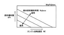
次いで、CPU61はステップ310に進み、燃料噴射量qfin、エンジン回転速度NE、及び図5に示したテーブルMapfinjbaseから基本燃料噴射時期finjbaseを決定する。テーブルMapfinjbaseは、燃料噴射量qfin及びエンジン回転速度NEと基本燃料噴射時期finjbaseとの関係を規定するテーブルであり、ROM62内に格納されている。 Next, the
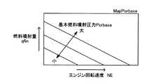
その後、CPU61はステップ315に進んで、燃料噴射量qfin、エンジン回転速度NE、及び図6に示したテーブルMapPcrbaseから基本燃料噴射圧力Pcrbaseを決定する。テーブルMapPcrbaseは、燃料噴射量qfin及びエンジン回転速度NEと基本燃料噴射圧力Pcrbaseとの関係を規定するテーブルであり、ROM62内に格納されている。 Thereafter, the
次に、CPU61はステップ320に進み、燃料噴射量qfin、エンジン回転速度NE、及び図7に示したテーブルMapNOxtから目標NOx排出量NOxtを決定する。テーブルMapNOxtは、燃料噴射量qfin及びエンジン回転速度NEと目標NOx排出量NOxtとの関係を規定するテーブルであり、ROM62内に格納されている。 Next, the
次いで、CPU61はステップ325に進んで、前記決定した目標NOx排出量NOxtから後述するルーチンにより求められている最新の(具体的には、前回の燃料噴射時期に演算された)実NOx排出量NOxactを減じた値をNOx排出量偏差ΔNOxとして格納する。 Next, the
続いて、CPU61はステップ330に進んで、噴射時期補正値Δθを、前記NOx排出量偏差ΔNOxと図8に示したテーブルMapΔθとから決定する。テーブルMapΔθは、NOx排出量偏差ΔNOxと噴射時期補正値Δθとの関係を規定するテーブルであり、ROM62内に格納されている。 Subsequently, the
次いで、CPU61はステップ335に進み、基本噴射時期finjbaseを噴射時期補正値Δθで補正して最終燃料噴射時期finjfinを決定する。これにより、NOx排出量偏差ΔNOxに応じて噴射時期が補正されることになる。この場合、図8から明らかなように、NOx排出量偏差ΔNOxが正の大きい値になるほど噴射時期補正値Δθが正の大きな値となって最終燃料噴射時期finjfinが進角側となり、同NOx排出量偏差ΔNOxが負の大きい値(絶対値が大きい値)になるほど噴射時期補正値Δθは負の大きな値となって最終燃料噴射時期finjfinが遅角側に移行される。 Next, the
続いて、CPU61はステップ340に進み、燃料噴射気筒についての噴射開始時期(即ち、上記決定された最終燃料噴射時期finjfin)が到来したか否かを判定し、「No」と判定する場合はステップ395に直ちに進んで本ルーチンを一旦終了する。 Subsequently, the
一方、ステップ340の判定において「Yes」と判定する場合、CPU61はステップ345に進んで上記決定された燃料噴射量qfinの燃料を燃料噴射気筒についての燃料噴射弁21から上記決定された基本燃料噴射圧力Pcrbaseをもって噴射するとともに、続くステップ350にて上記NOx排出量偏差ΔNOxが正の値であるか否かを判定し、「Yes」と判定する場合、ステップ355に進んでEGR制御弁52の開度を現時点での値よりも所定開度だけ小さくした後、ステップ370に進む。 On the other hand, if “Yes” is determined in the determination in
ステップ350の判定において「No」と判定する場合、CPU61はステップ360に進み、上記NOx排出量偏差ΔNOxが負の値であるか否かを判定する。ステップ360の判定において、CPU61は「Yes」と判定する場合、EGR制御弁52の開度を現時点での値よりも所定開度だけ大きくした後にステップ370に進む一方、「No」と判定する場合(即ち、NOx排出量偏差ΔNOxの値が「0」のとき)、EGR制御弁52の開度を変更することなくステップ370に進む。 If the determination in
このようにして、NOx排出量偏差ΔNOxに応じてEGR制御弁52の開度が変更される。そして、ステップ370に進むと、CPU61は実際に噴射した上記燃料噴射量qfinの値を値Qfuelとして格納した後、ステップ395に進んで本ルーチンを一旦終了する。以上により、燃料噴射量、燃料噴射時期、燃料噴射圧力、及びEGR制御弁52の開度の制御が達成される。 In this way, the opening degree of the
<NOx排出量の計算>
また、CPU61は、図9にフローチャートにより示した実NOx排出量NOxactの計算を行うためのルーチンを所定時間の経過毎に繰り返し実行するようになっている。従って、所定のタイミングになると、CPU61はステップ900から処理を開始し、ステップ905に進んで現時点がATDC-180°に一致しているか否かを判定する。<Calculation of NOx emissions>
In addition, the
いま、現時点がATDC-180°より前であるものとして説明を続けると、CPU61はステップ905にて「No」と判定してステップ935に直ちに進み、燃料噴射気筒についての燃料噴射開始時期(即ち、上記最終燃料噴射時期finjfin)が到来したか否かを判定する。現時点はATDC-180°よりも前であるから、CPU61はステップ935にて「No」と判定し、ステップ995に直ちに進んで本ルーチンを一旦終了する。 Now, assuming that the current time is before ATDC-180 °, the
以降、CPU61はATDC-180°が到来するまでの間、ステップ900、905、935、995の処理を繰り返し実行する。そして、ATDC-180°が到来すると、CPU61はステップ905に進んだとき「Yes」と判定してステップ910に進むようになり、ステップ910にて、吸気温センサ72、吸気管圧力センサ73、エアフローメータ71、及びクランクポジションセンサ74によりそれぞれ検出される現時点(即ち、ATDC-180°)での吸気温度Tb、吸気管圧力Pb、吸入新気流量Ga、及びエンジン回転速度NEを、それぞれ、下死点時筒内ガス温度Ta0、下死点時筒内ガス圧力Pa0、下死点時吸入新気流量Ga0、及び下死点時エンジン回転速度NE0として格納する。 Thereafter, the
次いで、CPU61はステップ915に進み、吸気酸素濃度センサ76により検出される現時点(即ち、ATDC-180°)での吸気酸素濃度RO2_inを下死点時吸気酸素濃度RO20_inとして格納し、続くステップ920にて、上記(1)式に従って筒内総ガス量Gcylを求める。ここで、下死点時筒内ガス圧力Pa0、及び下死点時筒内ガス温度Ta0としては、ステップ910にて格納されている値が用いられる。 Next, the
続いて、CPU61はステップ925に進んで、上記下死点時吸入新気流量Ga0と、上記下死点時エンジン回転速度NE0と、上記関数fとに基づいて吸入新気量Gmを求め、続くステップ930にて、ステップ920にて求めた筒内総ガス量Gcylと、前記吸入新気量Gmと、上記(5)式とに基づいてEGRガス量Gegrを求める。そして、CPU61はステップ935に進んで「No」と判定してステップ995に直ちに進んで本ルーチンを一旦終了する。 Subsequently, the
以降、CPU61は燃料噴射時期(即ち、上記最終燃料噴射時期finjfin)が到来するまでの間、ステップ900、905、935、995の処理を再び繰り返し実行する。そして、上記最終燃料噴射時期finjfinが到来すると、CPU61はステップ935にて「Yes」と判定してステップ940に進むようになり、ステップ940にて上記(4)式に従って吸気NOx濃度RNOx_inを求める。ここで、EGRガス量Gegr、及び筒内総ガス量Gcylとして、ステップ930、及びステップ920にて求められた値がそれぞれ使用される。排気NOx濃度RNOx_exとしては、前回の燃料噴射開始時期において後述するステップ975にて求められている値が使用される。 Thereafter, the
続いて、CPU61はステップ945に進んで、上記(2)式、及び上記(3)式に相当するステップ945内に記載の式に基づいてA領域還流NOx量NOxAを求める。ここで、値Qfuelとしては、図3のステップ370にて格納されている最新の値が使用される。次に、CPU61はステップ950に進み、前記値Qfuelと、現時点でのエンジン回転速度NEと、上記関数gとに基づいて燃焼発生NOx率RNOx_burnを求め、続くステップ955にて上記(7)式に従ってB領域燃焼発生NOx量NOxB1を求める。 Subsequently, the
次いで、CPU61はステップ960に進んで、上記(2)式、及び上記(6)式に相当するステップ960内に記載の式に基づいてB領域還流NOx量NOxB2を求め、続くステップ965にて上記B領域燃焼発生NOx量NOxB1と、上記B領域還流NOx量NOxB2の大きい方の値をB領域最終NOx量NOxBとして格納する。 Next, the
次に、CPU61はステップ970に進み、上記(8)式に従って排気NOx濃度RNOx_exを求めるとともに、続くステップ975にて上記(9)式に従って実NOx排出量NOxactを求め、ステップ995に進んで本ルーチンを一旦終了する。以降、CPU61は次の燃料噴射気筒についてのATDC-180°が到来するまでの間、ステップ900、905、935、995の処理を繰り返し実行する。 Next, the
以上のようにして、新たな実NOx排出量NOxactが燃料噴射開始時期が到来する毎に求められていく。そして、この新たな実NOx排出量NOxactは、前述のごとく、図3のステップ325にて使用され、この結果、次の燃料噴射気筒についての最終燃料噴射開始時期finjfin、及びEGR制御弁52の開度が同新たな実NOx排出量NOxactに基づいてフィードバック制御されていく。 As described above, a new actual NOx emission amount NOxact is obtained every time the fuel injection start timing comes. This new actual NOx emission amount NOxact is used in
以上、説明したように、本発明の実施形態に係る内燃機関のNOx排出量推定方法によれば、燃焼室内に吸入された吸気中の各ガス成分(酸素分子、NOx等)は同燃焼室内全域に渡ってそれぞれ均一に分布するとの仮定のもと、「燃焼室内に吸入された酸素の全質量」に対する「燃焼により消費される酸素の質量」の割合を利用して、同燃焼室が、燃焼領域(B領域)と非燃焼領域(A領域)とに区別される。そして、燃焼後において、B領域には燃焼により発生した燃焼発生NOx量(実際には、上記B領域最終NOx量NOxB)が残存するともに、A領域では燃焼前に存在していたA領域還流NOx量NOxAがそのまま燃焼後も保存される(残存する)との仮定のもと、B領域にて発生する燃料発生NOx量のみならずA領域還流NOx量NOxAをも考慮して、排気通路から外部へ排出される排ガス中の実NOx排出量NOxactが計算される。従って、実NOx排出量NOxactが精度良く推定された。 As described above, according to the NOx emission estimation method for the internal combustion engine according to the embodiment of the present invention, each gas component (oxygen molecules, NOx, etc.) in the intake air sucked into the combustion chamber is distributed over the entire combustion chamber. Using the ratio of “mass of oxygen consumed by combustion” to “total mass of oxygen sucked into the combustion chamber”, assuming that the combustion chamber A distinction is made between regions (B regions) and non-combustion regions (A regions). After combustion, the amount of combustion-generated NOx generated by combustion (actually, the above-mentioned B region final NOx amount NOxB) remains in the B region, and the A region reflux NOx that existed before the combustion in the A region. Under the assumption that the amount of NOxA is preserved (remains) after combustion, the exhaust passage is externally taken into account not only the amount of fuel-generated NOx generated in region B but also the amount of NOxA recirculating NOxA. The actual NOx emission amount NOxact in the exhaust gas discharged to is calculated. Therefore, the actual NOx emission amount NOxact was accurately estimated.
本発明は上記実施形態に限定されることはなく、本発明の範囲内において種々の変形例を採用することができる。例えば、上記実施形態においては、機関10の運転状態にかかわらず燃料噴射開始時期が到来する毎にNOx排出量(実NOx排出量NOxact)を計算しているが、機関10が所定の定常運転状態にある場合に限りNOx排出量を計算するように構成してもよい。 The present invention is not limited to the above embodiment, and various modifications can be employed within the scope of the present invention. For example, in the above embodiment, the NOx emission amount (actual NOx emission amount NOxact) is calculated every time the fuel injection start timing comes regardless of the operation state of the
また、上記実施形態においては、「燃焼後にB領域内に残存するNOx質量」として、上記(7)式に従って求められるB領域燃焼発生NOx量NOxB1と、上記(6)式に従って求められるB領域還流NOx量NOxB2のうち大きい方の値(B領域最終NOx量NOxB)を採用しているが、「燃焼後にB領域内に残存するNOx質量」として、常に上記B領域燃焼発生NOx量NOxB1を採用してもよい。 Further, in the above embodiment, as “NOx mass remaining in the B region after combustion”, the B region combustion generated NOx amount NOxB1 obtained according to the above equation (7) and the B region reflux obtained according to the above equation (6) The larger value of the NOx amount NOxB2 (B region final NOx amount NOxB) is adopted, but the above-mentioned B region combustion generated NOx amount NOxB1 is always adopted as the “NOx mass remaining in the B region after combustion”. May be.
また、上記実施形態においては、機関10が、一作動サイクル中において1回で必要な量(燃料噴射量qfin)の燃料を噴射するように構成されているが、一作動サイクル中においてパイロット噴射とメイン噴射とに分けて同量の燃料を噴射するように構成されている場合、パイロット噴射により発生する不活性ガスの影響を考慮して、例えば、パイロット噴射による燃料噴射量、或いは、同パイロット噴射の時期等に基づいて上記燃焼発生NOx率RNOx_burnの値を所定量だけ小さくなる方向に補正するように構成してもよい。 In the above-described embodiment, the
21…燃料噴射弁、22…燃料噴射用ポンプ、31…吸気マニホールド、32…吸気管、41…排気マニホールド、42…排気管、50…EGR装置、52…EGR制御弁、60…電気制御装置、61…CPU、71…エアフローメータ、72…吸気温センサ、73…吸気管圧力センサ、74…クランクポジションセンサ、76…吸気酸素濃度センサ
DESCRIPTION OF
Claims (7)
Translated fromJapanese燃焼室内において燃焼が発生する領域である燃焼領域を推定するとともに、
前記燃焼領域内にて燃焼により発生する燃焼発生NOx量と、前記燃焼室内における前記燃焼領域を除いた領域である非燃焼領域内におけるNOx量とを推定し、
前記燃焼発生NOx量と、前記非燃焼領域内におけるNOx量とに基づいて、前記排気通路から外部へ排出される排ガス中のNOx量を推定する内燃機関のNOx排出量推定方法。A NOx emission amount estimation method applied to an internal combustion engine provided with an EGR device that recirculates a part of exhaust gas flowing through an exhaust passage of the internal combustion engine to an intake passage of the internal combustion engine,
Estimating the combustion region, where combustion occurs in the combustion chamber,
Estimating the amount of combustion-generated NOx generated by combustion in the combustion region and the amount of NOx in a non-combustion region that is a region excluding the combustion region in the combustion chamber;
An internal combustion engine NOx emission amount estimation method for estimating an NOx amount in exhaust gas discharged from the exhaust passage to the outside based on the combustion-generated NOx amount and the NOx amount in the non-combustion region.
前記非燃焼領域内におけるNOx量を推定するにあたり、
前記EGR装置を介して前記燃焼室内に還流してきたNOx量のうち燃焼前に前記非燃焼領域内に存在する非燃焼領域還流NOx量を、同非燃焼領域内におけるNOx量として推定することを特徴とする内燃機関のNOx排出量推定方法。In the internal combustion engine NOx emission amount estimation method according to claim1 ,
In estimating the amount of NOx in the non-combustion region,
Of the NOx amount recirculated into the combustion chamber via the EGR device, the non-combustion region recirculation NOx amount existing in the non-combustion region before combustion is estimated as the NOx amount in the non-combustion region. A NOx emission amount estimation method for an internal combustion engine.
前記燃焼発生NOx量を推定するにあたり、
前記EGR装置を介して前記燃焼室内に還流してきたNOx量のうち燃焼前に前記燃焼領域内に存在する燃焼領域還流NOx量と、前記燃焼発生NOx量のうち大きい方を同燃焼発生NOx量として推定することを特徴とする内燃機関のNOx排出量推定方法。In the internal combustion engine NOx emission amount estimation method according to claim1 or2 ,
In estimating the combustion generated NOx amount,
Of the NOx amount recirculated into the combustion chamber via the EGR device, the larger one of the combustion region recirculation NOx amount existing in the combustion region before combustion and the combustion generated NOx amount is defined as the combustion generated NOx amount. An NOx emission amount estimation method for an internal combustion engine, characterized by estimating.
前記排気通路から外部へ排出されるNOx量を推定するにあたり、
前記燃焼発生NOx量と前記非燃焼領域内におけるNOx量とに基づいて排ガス中のNOx濃度を推定するとともに、同NOx濃度に前記排気通路から外部へ排出される排ガス量を乗じた値を前記排気通路から外部へ排出されるNOx量として推定することを特徴とする内燃機関のNOx排出量推定方法。In NOx emissions estimation method for an internal combustion engine according to any one of claims1 to3,
In estimating the amount of NOx discharged from the exhaust passage to the outside,
A NOx concentration in the exhaust gas is estimated based on the NOx amount generated in the combustion and the NOx amount in the non-combustion region, and a value obtained by multiplying the NOx concentration by the amount of exhaust gas discharged from the exhaust passage to the outside is used. A NOx emission amount estimation method for an internal combustion engine, characterized by estimating the amount of NOx emitted from a passage to the outside.
前記吸気通路に吸入される新気量を前記排気通路から外部へ排出される排ガス量として推定することを特徴とする内燃機関のNOx排出量推定方法。In the internal combustion engine NOx emission estimation method according to claim4 ,
A method for estimating a NOx emission amount of an internal combustion engine, wherein the amount of fresh air taken into the intake passage is estimated as an amount of exhaust gas discharged from the exhaust passage to the outside.
前記燃焼領域を推定するにあたり、
前記燃焼室内に吸入された酸素量と、燃焼により消費される酸素量とを推定するとともに、前記燃焼室内に吸入された酸素量に対する前記燃焼により消費される酸素量の割合を利用して前記燃焼領域を推定することを特徴とする内燃機関のNOx排出量推定方法。In the NOx emission amount estimation method for an internal combustion engine according to any one of claims1 to5,
In estimating the combustion region,
Estimating the amount of oxygen sucked into the combustion chamber and the amount of oxygen consumed by combustion, and utilizing the ratio of the amount of oxygen consumed by the combustion to the amount of oxygen sucked into the combustion chamber An NOx emission amount estimation method for an internal combustion engine characterized by estimating a region.
前記内燃機関が一作動サイクル中において少なくとも1回燃料をパイロット噴射した後に同燃料をメイン噴射するように構成されている場合、
前記燃焼発生NOx量を推定するにあたり、前記パイロット噴射により発生する不活性ガスの影響を更に考慮して同燃焼発生NOx量を推定することを特徴とする内燃機関のNOx排出量推定方法。In NOx emissions estimation method for an internal combustion engine according to any one of claims1 to6,
When the internal combustion engine is configured to perform main injection of the fuel after pilot injection of the fuel at least once during one operation cycle,
A method for estimating the NOx emission amount of an internal combustion engine, wherein the NOx amount of combustion generated is estimated in consideration of the influence of an inert gas generated by the pilot injection in estimating the NOx amount of combustion generated.
Priority Applications (6)
| Application Number | Priority Date | Filing Date | Title |
|---|---|---|---|
| JP2003376456AJP3925485B2 (en) | 2003-11-06 | 2003-11-06 | NOx emission estimation method for internal combustion engine |
| EP04773805AEP1682759B1 (en) | 2003-11-06 | 2004-10-14 | NOx DISCHARGE QUANTITY ESTIMATION METHOD FOR INTERNAL COMBUSTION ENGINE |
| US10/540,012US7281368B2 (en) | 2003-11-06 | 2004-10-14 | Nox discharge quantity estimation method for internal combustion engine |
| CNB2004800033993ACN100381690C (en) | 2003-11-06 | 2004-10-14 | Nox discharge quantity estimation method for internal combustion engine |
| DE602004020650TDE602004020650D1 (en) | 2003-11-06 | 2004-10-14 | METHOD FOR ESTIMATING A NOX DELIVERY QUANTITY FOR A COMBUSTION ENGINE |
| PCT/JP2004/015545WO2005045219A1 (en) | 2003-11-06 | 2004-10-14 | Nox discharge quantity estimation method for internal combustion engine |
Applications Claiming Priority (1)
| Application Number | Priority Date | Filing Date | Title |
|---|---|---|---|
| JP2003376456AJP3925485B2 (en) | 2003-11-06 | 2003-11-06 | NOx emission estimation method for internal combustion engine |
Publications (2)
| Publication Number | Publication Date |
|---|---|
| JP2005139983A JP2005139983A (en) | 2005-06-02 |
| JP3925485B2true JP3925485B2 (en) | 2007-06-06 |
Family
ID=34567111
Family Applications (1)
| Application Number | Title | Priority Date | Filing Date |
|---|---|---|---|
| JP2003376456AExpired - Fee RelatedJP3925485B2 (en) | 2003-11-06 | 2003-11-06 | NOx emission estimation method for internal combustion engine |
Country Status (6)
| Country | Link |
|---|---|
| US (1) | US7281368B2 (en) |
| EP (1) | EP1682759B1 (en) |
| JP (1) | JP3925485B2 (en) |
| CN (1) | CN100381690C (en) |
| DE (1) | DE602004020650D1 (en) |
| WO (1) | WO2005045219A1 (en) |
Families Citing this family (39)
| Publication number | Priority date | Publication date | Assignee | Title |
|---|---|---|---|---|
| JP4735519B2 (en)* | 2006-11-17 | 2011-07-27 | トヨタ自動車株式会社 | Exhaust gas recirculation device for internal combustion engine |
| JP4776566B2 (en)* | 2007-02-28 | 2011-09-21 | 本田技研工業株式会社 | Fuel control device for internal combustion engine |
| WO2008131789A1 (en)* | 2007-04-26 | 2008-11-06 | Fev Motorentechnik Gmbh | System for controlling the exhaust gas return rate by means of virtual nox sensors with adaptation via a nox sensor |
| US7831378B2 (en)* | 2007-10-30 | 2010-11-09 | Cummins Inc. | System and method for estimating NOx produced by an internal combustion engine |
| GB2461301B (en)* | 2008-06-27 | 2012-08-22 | Gm Global Tech Operations Inc | A method for detecting faults in the air system of internal combustion engines |
| JP2011021595A (en)* | 2009-06-15 | 2011-02-03 | Ngk Spark Plug Co Ltd | Intake system for internal combustion engine |
| US8010276B2 (en)* | 2009-08-31 | 2011-08-30 | International Engine Intellectual Property Company, Llc | Intake manifold oxygen control |
| EP2474731B1 (en)* | 2009-09-03 | 2020-08-19 | Toyota Jidosha Kabushiki Kaisha | Exhaust recirculation device for internal combustion engine |
| US8117906B2 (en)* | 2010-05-05 | 2012-02-21 | Ford Global Technologies, Llc | Gas sensor shield without perforations |
| DE102010030404A1 (en)* | 2010-06-23 | 2011-12-29 | Robert Bosch Gmbh | Method for operating an internal combustion engine |
| US9181904B2 (en)* | 2010-08-10 | 2015-11-10 | Ford Global Technologies, Llc | Method and system for exhaust gas recirculation control |
| DE102010056514A1 (en) | 2010-12-31 | 2012-07-05 | Fev Gmbh | Method for reduction of nitrogen oxide emission in diesel engine of motor car, involves providing parts of exhaust gas to form residue exhaust gas in chamber, and adjusting residue gas and/or ratio between parts of gas in chamber |
| DE102011017036B4 (en)* | 2011-04-14 | 2015-02-19 | Mtu Friedrichshafen Gmbh | Method for controlling the NOx concentration in the exhaust gas of an internal combustion engine |
| US9677493B2 (en) | 2011-09-19 | 2017-06-13 | Honeywell Spol, S.R.O. | Coordinated engine and emissions control system |
| US20130111905A1 (en) | 2011-11-04 | 2013-05-09 | Honeywell Spol. S.R.O. | Integrated optimization and control of an engine and aftertreatment system |
| US9650934B2 (en) | 2011-11-04 | 2017-05-16 | Honeywell spol.s.r.o. | Engine and aftertreatment optimization system |
| JP5831162B2 (en)* | 2011-11-18 | 2015-12-09 | いすゞ自動車株式会社 | NOx sensor abnormality diagnosis method, NOx sensor abnormality diagnosis system, and internal combustion engine |
| KR101317413B1 (en)* | 2011-11-22 | 2013-10-10 | 서울대학교산학협력단 | System and method for controlling nox |
| JP5269174B2 (en) | 2011-11-28 | 2013-08-21 | 株式会社豊田自動織機 | Exhaust gas purification device in internal combustion engine |
| DE102013212217A1 (en)* | 2012-07-12 | 2014-05-15 | Ford Global Technologies, Llc | Indirect measurement of relative humidity |
| CN104797801B (en)* | 2012-11-19 | 2017-05-10 | 丰田自动车株式会社 | Control devices for internal combustion engines |
| US20160032802A1 (en)* | 2013-03-18 | 2016-02-04 | Yanmar Co., Ltd. | Exhaust purification system and ship comprising same |
| US9328679B2 (en)* | 2013-10-11 | 2016-05-03 | Ford Global Technologies, Llc | Methods and systems for an oxygen sensor |
| EP3051367B1 (en) | 2015-01-28 | 2020-11-25 | Honeywell spol s.r.o. | An approach and system for handling constraints for measured disturbances with uncertain preview |
| WO2016130517A1 (en)* | 2015-02-10 | 2016-08-18 | Cummins, Inc. | SYSTEM AND METHOD FOR DETERMINING ENGINE OUT NOx BASED ON IN-CYLINDER CONTENTS |
| EP3056706A1 (en) | 2015-02-16 | 2016-08-17 | Honeywell International Inc. | An approach for aftertreatment system modeling and model identification |
| EP3091212A1 (en) | 2015-05-06 | 2016-11-09 | Honeywell International Inc. | An identification approach for internal combustion engine mean value models |
| EP3734375B1 (en) | 2015-07-31 | 2023-04-05 | Garrett Transportation I Inc. | Quadratic program solver for mpc using variable ordering |
| WO2017023758A1 (en)* | 2015-08-05 | 2017-02-09 | Cummins Emission Solutions Inc. | Oxygen correction for engine-out nox estimates using a nox sensor of an aftertreatment system |
| US10272779B2 (en) | 2015-08-05 | 2019-04-30 | Garrett Transportation I Inc. | System and approach for dynamic vehicle speed optimization |
| DE102015216303B3 (en)* | 2015-08-26 | 2016-09-29 | Ford Global Technologies, Llc | Correction of an injected fuel quantity |
| JP6477435B2 (en)* | 2015-11-12 | 2019-03-06 | 株式会社デンソー | Combustion system estimation device |
| US10415492B2 (en) | 2016-01-29 | 2019-09-17 | Garrett Transportation I Inc. | Engine system with inferential sensor |
| US10124750B2 (en) | 2016-04-26 | 2018-11-13 | Honeywell International Inc. | Vehicle security module system |
| US10036338B2 (en) | 2016-04-26 | 2018-07-31 | Honeywell International Inc. | Condition-based powertrain control system |
| US11199120B2 (en) | 2016-11-29 | 2021-12-14 | Garrett Transportation I, Inc. | Inferential flow sensor |
| US11057213B2 (en) | 2017-10-13 | 2021-07-06 | Garrett Transportation I, Inc. | Authentication system for electronic control unit on a bus |
| KR102506940B1 (en)* | 2018-09-28 | 2023-03-07 | 현대자동차 주식회사 | METHOD OF PREDICTING AND CONTROLLING NOx GENERATION AMOUNT |
| DK180561B1 (en)* | 2020-03-06 | 2021-06-24 | Man Energy Solutions Filial Af Man Energy Solutions Se Tyskland | An internal combustion engine configured for determining specific emissions and a method for determining specific emissions of an internal combustion engine |
Family Cites Families (14)
| Publication number | Priority date | Publication date | Assignee | Title |
|---|---|---|---|---|
| US5775099A (en)* | 1994-04-12 | 1998-07-07 | Toyota Jidosha Kabushiki Kaisha | Method of purifying the exhaust of an internal combustion engine |
| JPH0988691A (en)* | 1995-09-20 | 1997-03-31 | Toyota Motor Corp | Compression ignition internal combustion engine |
| JP3465490B2 (en)* | 1996-09-09 | 2003-11-10 | トヨタ自動車株式会社 | Exhaust gas purification device for internal combustion engine |
| DE19851319C2 (en)* | 1998-11-06 | 2003-03-20 | Siemens Ag | Method for determining the raw NOx emission of an internal combustion engine that can be operated with excess air |
| JP3632483B2 (en)* | 1999-02-05 | 2005-03-23 | マツダ株式会社 | Engine control device |
| JP3693855B2 (en) | 1999-06-07 | 2005-09-14 | 三菱電機株式会社 | Air-fuel ratio control device for internal combustion engine |
| JP4491932B2 (en) | 2000-08-07 | 2010-06-30 | マツダ株式会社 | Engine exhaust purification system |
| EP1182340B1 (en)* | 2000-08-22 | 2005-06-08 | Mazda Motor Corporation | Exhaust gas purifying system for engine |
| DE10043383C2 (en)* | 2000-09-02 | 2002-06-20 | Daimler Chrysler Ag | Method for determining the nitrogen oxide content in oxygen-containing exhaust gases from internal combustion engines |
| JP2002195071A (en) | 2000-12-25 | 2002-07-10 | Mitsubishi Electric Corp | Internal combustion engine control device |
| JP4393726B2 (en)* | 2001-04-09 | 2010-01-06 | 本田技研工業株式会社 | Exhaust gas recirculation control device for internal combustion engine |
| JP4706134B2 (en)* | 2001-06-15 | 2011-06-22 | トヨタ自動車株式会社 | Control device for internal combustion engine |
| US6697729B2 (en) | 2002-04-08 | 2004-02-24 | Cummins, Inc. | System for estimating NOx content of exhaust gas produced by an internal combustion engine |
| US6775623B2 (en) | 2002-10-11 | 2004-08-10 | General Motors Corporation | Real-time nitrogen oxides (NOx) estimation process |
- 2003
- 2003-11-06JPJP2003376456Apatent/JP3925485B2/ennot_activeExpired - Fee Related
- 2004
- 2004-10-14EPEP04773805Apatent/EP1682759B1/ennot_activeExpired - Lifetime
- 2004-10-14DEDE602004020650Tpatent/DE602004020650D1/ennot_activeExpired - Lifetime
- 2004-10-14WOPCT/JP2004/015545patent/WO2005045219A1/enactiveApplication Filing
- 2004-10-14CNCNB2004800033993Apatent/CN100381690C/ennot_activeExpired - Fee Related
- 2004-10-14USUS10/540,012patent/US7281368B2/ennot_activeExpired - Fee Related
Also Published As
| Publication number | Publication date |
|---|---|
| CN100381690C (en) | 2008-04-16 |
| DE602004020650D1 (en) | 2009-05-28 |
| US20060107651A1 (en) | 2006-05-25 |
| EP1682759A1 (en) | 2006-07-26 |
| WO2005045219A1 (en) | 2005-05-19 |
| CN1745236A (en) | 2006-03-08 |
| EP1682759B1 (en) | 2009-04-15 |
| US7281368B2 (en) | 2007-10-16 |
| JP2005139983A (en) | 2005-06-02 |
Similar Documents
| Publication | Publication Date | Title |
|---|---|---|
| JP3925485B2 (en) | NOx emission estimation method for internal combustion engine | |
| JP3861869B2 (en) | NOx generation amount estimation method for internal combustion engine | |
| CN100360780C (en) | EGR control device and method for internal combustion engine | |
| JP4126560B2 (en) | Control device for internal combustion engine | |
| JP3861046B2 (en) | EGR gas flow rate estimation device for internal combustion engine | |
| JP3751930B2 (en) | EGR gas temperature estimation device for internal combustion engine | |
| RU2616727C2 (en) | Engine operating process (versions) and system | |
| US8875488B2 (en) | Internal combustion engine | |
| CN101743392A (en) | Internal combustion engine control device and method | |
| JP3965584B2 (en) | Method for estimating combustion temperature of internal combustion engine | |
| JP4232524B2 (en) | Engine control device | |
| CN111315976B (en) | Control system for a vehicle powertrain and method of operating a vehicle powertrain | |
| JP4862735B2 (en) | Fuel injection amount control device for internal combustion engine | |
| JP5240417B2 (en) | Diffusion combustion start timing estimation device and diffusion combustion start timing control device for internal combustion engine | |
| JP2005226460A (en) | Method for estimating mixture concentration in internal combustion engine | |
| JP4196798B2 (en) | In-cylinder gas temperature estimation method and cylinder gas pressure estimation method for internal combustion engine | |
| JP7323416B2 (en) | Estimation method for determining the concentration of recirculated exhaust gas present in the cylinder of an internal combustion engine | |
| JP2005180219A (en) | Method for learning NOx generation amount estimation model of internal combustion engine | |
| JP5695878B2 (en) | Combustion control apparatus and method for internal combustion engine | |
| JP4175743B2 (en) | Exhaust gas recirculation device and oxygen excess rate calculation method | |
| JP2004346917A (en) | Internal combustion engine control device | |
| CN112654777A (en) | Method for controlling an air-gasoline injector of an internal combustion engine | |
| KR102460277B1 (en) | Eexhaust gas recirculation control method and system during high load operation and combustion engine vehicle including the same system | |
| JP2005023819A (en) | Air-fuel ratio control device for internal combustion engine |
Legal Events
| Date | Code | Title | Description |
|---|---|---|---|
| A131 | Notification of reasons for refusal | Free format text:JAPANESE INTERMEDIATE CODE: A131 Effective date:20061107 | |
| A521 | Written amendment | Free format text:JAPANESE INTERMEDIATE CODE: A523 Effective date:20061226 | |
| TRDD | Decision of grant or rejection written | ||
| A01 | Written decision to grant a patent or to grant a registration (utility model) | Free format text:JAPANESE INTERMEDIATE CODE: A01 Effective date:20070206 | |
| A61 | First payment of annual fees (during grant procedure) | Free format text:JAPANESE INTERMEDIATE CODE: A61 Effective date:20070219 | |
| FPAY | Renewal fee payment (event date is renewal date of database) | Free format text:PAYMENT UNTIL: 20110309 Year of fee payment:4 | |
| FPAY | Renewal fee payment (event date is renewal date of database) | Free format text:PAYMENT UNTIL: 20110309 Year of fee payment:4 | |
| FPAY | Renewal fee payment (event date is renewal date of database) | Free format text:PAYMENT UNTIL: 20120309 Year of fee payment:5 | |
| FPAY | Renewal fee payment (event date is renewal date of database) | Free format text:PAYMENT UNTIL: 20120309 Year of fee payment:5 | |
| FPAY | Renewal fee payment (event date is renewal date of database) | Free format text:PAYMENT UNTIL: 20130309 Year of fee payment:6 | |
| FPAY | Renewal fee payment (event date is renewal date of database) | Free format text:PAYMENT UNTIL: 20130309 Year of fee payment:6 | |
| FPAY | Renewal fee payment (event date is renewal date of database) | Free format text:PAYMENT UNTIL: 20140309 Year of fee payment:7 | |
| LAPS | Cancellation because of no payment of annual fees |