JP3925407B2 - Charger - Google Patents
ChargerDownload PDFInfo
- Publication number
- JP3925407B2 JP3925407B2JP2002379012AJP2002379012AJP3925407B2JP 3925407 B2JP3925407 B2JP 3925407B2JP 2002379012 AJP2002379012 AJP 2002379012AJP 2002379012 AJP2002379012 AJP 2002379012AJP 3925407 B2JP3925407 B2JP 3925407B2
- Authority
- JP
- Japan
- Prior art keywords
- lid
- charged
- main body
- charging device
- guide hole
- Prior art date
- Legal status (The legal status is an assumption and is not a legal conclusion. Google has not performed a legal analysis and makes no representation as to the accuracy of the status listed.)
- Expired - Fee Related
Links
- 230000015572biosynthetic processEffects0.000claimsdescription2
- 230000000694effectsEffects0.000description7
- 230000006835compressionEffects0.000description3
- 238000007906compressionMethods0.000description3
- 239000004973liquid crystal related substanceSubstances0.000description3
- 238000007639printingMethods0.000description3
- 238000011109contaminationMethods0.000description2
- 229920000742CottonPolymers0.000description1
- 238000005452bendingMethods0.000description1
- 238000010586diagramMethods0.000description1
- 238000007641inkjet printingMethods0.000description1
- 239000000463materialSubstances0.000description1
- 230000000452restraining effectEffects0.000description1
Images


Classifications
- Y—GENERAL TAGGING OF NEW TECHNOLOGICAL DEVELOPMENTS; GENERAL TAGGING OF CROSS-SECTIONAL TECHNOLOGIES SPANNING OVER SEVERAL SECTIONS OF THE IPC; TECHNICAL SUBJECTS COVERED BY FORMER USPC CROSS-REFERENCE ART COLLECTIONS [XRACs] AND DIGESTS
- Y02—TECHNOLOGIES OR APPLICATIONS FOR MITIGATION OR ADAPTATION AGAINST CLIMATE CHANGE
- Y02E—REDUCTION OF GREENHOUSE GAS [GHG] EMISSIONS, RELATED TO ENERGY GENERATION, TRANSMISSION OR DISTRIBUTION
- Y02E60/00—Enabling technologies; Technologies with a potential or indirect contribution to GHG emissions mitigation
- Y02E60/10—Energy storage using batteries
Landscapes
- Charge And Discharge Circuits For Batteries Or The Like (AREA)
- Secondary Cells (AREA)
- Telephone Set Structure (AREA)
Description
Translated fromJapanese【0001】
【発明の属する技術分野】
本発明は、充電されることにより動作可能な、たとえば携帯電話またはコードレス子機などの被充電機器を充電するための充電装置に関する。
【0002】
【従来の技術】
従来より、一般家庭などで用いられている電話機には、携帯可能なコードレス子機などの被充電機器が付属されていることが多い。このような被充電機器は、携帯可能であるが、ユーザが未使用の場合には、電話機本体と別体に設けられた載置台に、あるいは電話機本体に一体的に設けられた載置台に載置される。また、被充電機器は、通常、その内部に備えられたバッテリが充電されることによって動作することから、上記載置台が被充電機器に対して充電を行うための充電器としての機能を兼ね備えている場合が多い。すなわち、被充電機器を上記載置台に載置すると、必要に応じて充電が行われる(たとえば、特許文献1参照)。
【0003】
【特許文献1】
特開2000−14022号公報
【0004】
このような載置台を有する充電装置においては、被充電機器の電極部と接触するための端子部材が設けられている。この充電装置では、端子部材を外部に露出させていると、端子部材におけるたとえば接触面の汚れや酸化皮膜の形成などにより被充電機器の電極部との間で接触不良を生じることがある。このような不具合を抑制するために、たとえば、被充電機器の非載置状態のときには、端子部材を外部に露出させないようにした蓋体が設けられた構成の充電装置が提案されている。
【0005】
図8は、このような充電装置がファクシミリ装置と一体的に設けられる場合の外観図である。この充電装置1によれば、充電装置1の本体3上面に、端子部材(図示略)を覆う蓋体4が設けられ、被充電機器Pが蓋体4を上部から押圧することにより、蓋体4が開放され、被充電機器Pが端子部材と接触して被充電機器Pの充電が行われる。
【0006】
【発明が解決しようとする課題】
この充電装置1では、被充電機器Pを立たせたまま載置させるが、このようなタイプの充電装置1にあっては、装置高さをできるだけ低くしたいといったデザイン上の要請がある場合がある。たとえば、図8に示す充電装置1の場合、充電装置1をファクシミリ装置2の手前側の側方に配置させておくと、ユーザが被充電機器Pを着脱する上で望ましい。しかしながら、充電装置1をファクシミリ装置2の手前側に配置させたとき、充電装置1の上面がファクシミリ装置2の上面から出っ張るようになり、ファクシミリ装置2の全体の見栄えを悪化させる。
【0007】
そのため、充電装置1の装置高さをできる限り、低くすることが望まれる。しかしながら、装置高さを低くすると、図9および図10に示すように、蓋体4が被充電機器Pに押圧されて軸91周りに回転したとき、蓋体4の先端が端子部材92に衝突してしまい、端子部材92に損傷を与えるといった不都合が生じる。
【0008】
この場合、蓋体4の前後方向における寸法を短くすることも考えられるが、蓋体4の前後方向における寸法を短くすると、被充電機器Pを充電装置1に載置させるとき、被充電機器Pを収容させるための十分な開口スペースを確保することが困難になるといった弊害が生じる。
【0009】
本発明は、上記の点に鑑みて提案されたものであって、装置高さを低く抑えつつ、蓋体を良好に開閉することのできる充電装置を提供することを目的とする。
【0010】
【課題を解決するための手段】
上記目的を達成するために、請求項1に記載した発明の充電装置は、本体と、この本体内に設けられ、充電されることにより動作可能な被充電機器を収容する収容部と、この収容部に設けられ、収容される前記被充電機器に対向するように突出した端子部材と、前記本体の内側に向けて退入するように支持され、前記本体の上面を覆う蓋体とを備え、前記蓋体を外部から押圧することにより前記蓋体を開放状態にするとともに、前記収容部に収容される前記被充電機器を、前記端子部材を介して充電するための充電装置であって、前記蓋体の両側端部から直交方向に延びた支持部材に形成された第1の案内部材と、前記本体の両側面に沿って設けられ、前記第1の案内部材と係合して相対移動する第2の案内部材を有する側板部材と、前記蓋体に対する前記被充電機器の押圧力に抗して前記蓋体を閉塞状態に付勢する弾性部材と、を備え、前記被充電機器によって前記蓋体が前記本体の内側に向けて押圧されるとき、一方の案内部材が前記蓋体の退入動作の軸とされつつ、他方の案内部材と係合して相対移動されることにより、前記蓋体の先端が前記端子部材を回避するようにして前記蓋体が移動するように構成されたことを特徴としている。ここで、第1の案内部材として突起部材が適用されたときは、第2の案内部材として案内孔が適用され、逆に第1の案内部材として案内孔が適用されたときは、第2の案内部材として突起部材が適用される。
【0011】
このような充電装置によれば、被充電機器によって蓋体が押圧されるとき、一方の案内部材が蓋体の退入動作の軸とされつつ、他方の案内部材と係合して相対移動される。そのため、たとえば固定された軸周りに蓋体が開放動作する場合に比べ、蓋体の先端がなだらかな曲線を描くようにして蓋体が開放動作することになるので、蓋体の先端が端子部材を回避するようにして蓋体が開放動作する。したがって、装置高さを抑えつつ、蓋体が良好に開閉する充電装置を提供することができる。
【0012】
また、請求項2に記載した発明の充電装置は、本体と、この本体内に設けられ、充電されることにより動作可能な被充電機器を収容する収容部と、この収容部に設けられ、収容される前記被充電機器に対向するように突出した端子部材と、前記本体の内側に向けて退入するように支持され、前記本体の上面を覆う蓋体とを備え、前記蓋体を外部から押圧することにより前記蓋体を開放状態にするとともに、前記収容部に収容される前記被充電機器を、前記端子部材を介して充電するための充電装置であって、前記蓋体の両側端部から直交方向に延びた支持部材に形成された第1の突起部材と、前記本体の両側面に沿って設けられ、前記第1の突起部材を案内するための略水平方向に延びた第1の案内孔を有する側板部材と、前記蓋体に対する前記被充電機器の押圧力に抗して前記蓋体を閉塞状態に付勢する弾性部材と、を備え、前記被充電機器によって前記蓋体が前記本体の内側に向けて押圧されるとき、前記第1の突起部材が前記蓋体の退入動作の軸とされつつ、前記第1の案内孔に沿ってスライド移動されることにより、前記蓋体の先端が前記端子部材を回避するようにして前記蓋体が移動するように構成されたことを特徴としている。
【0013】
このような充電装置によれば、被充電機器によって蓋体が押圧されるとき、第1の突起部材が蓋体の退入動作の軸とされつつ、第1の案内孔に沿ってスライド移動される。そのため、たとえば固定された軸周りに蓋体が開放動作する場合に比べ、蓋体の先端がなだらかな曲線を描くようにして蓋体が開放動作することになるので、蓋体の先端が端子部材を回避するようにして蓋体が開放動作する。したがって、装置高さを抑えつつ、蓋体が良好に開閉する充電装置を提供することができる。
【0014】
また、請求項3に記載した発明の充電装置は、請求項2に記載の充電装置であって、前記支持部材には、前記第1の突起部材の形成位置から前記支持部材の延出方向に所定間隔を隔てて第2の突起部材が形成されており、前記側板部材には、前記第1の突起部材を案内するための略湾曲状に延びた第2の案内孔が形成されており、前記被充電機器によって前記蓋体が前記本体の内側に向けて押圧される際、前記第2の突起部材が前記第2の案内孔に沿って案内されることにより、前記第1の突起部材の前記第1の案内孔におけるスライド移動の開始を補助する。
【0015】
このような充電装置によれば、請求項2に記載の充電装置による効果に加え、被充電機器によって蓋体が押圧されるとき、第2の突起部材が第2の案内孔に沿って案内されることにより、第1の突起部材が第1の案内孔に沿ってスライド移動するときのその移動の開始を補助する。そのため、第1の突起部材をよりスムーズかつ確実にスライド移動させることができる。
【0016】
また、請求項4に記載した発明の充電装置は、請求項3に記載の充電装置であって、前記第2の案内孔は、前記被充電機器によって前記蓋体が押圧されるとき、前記第2の突起部材が移動する第1の円弧部と、この第1の円弧部とは異なる曲率半径を有し、かつ前記第1の突起部材が前記第1の案内孔の終端部に到達したとき、その第1の突起部材を軸にしてこの軸周りに前記第2の突起部材が回転移動する第2の円弧部とを有する。
【0017】
このような充電装置によれば、請求項3に記載の充電装置による効果に加え、第2の突起部材が第1の円弧部を移動するとき、第2の突起部材によって第1の突起部材の第1の案内孔内におけるスライド移動の開始を補助することができる。また、第1の突起部材が第1の案内孔の終端部に到達したとき、すなわち、蓋体の先端が端子部材を回避するようにして蓋体が開放移動した後、第2の突起部材が第2の円弧部を移動するとき、第1の突起部材を軸にしてこの軸周りに第2の突起部材が回転移動する。これにより、第2の突起部材は、比較的小さな回転半径で回転することができ、本体内の蓋体による開放容積を小さくすることができる。そのため、被充電機器の載置スペースを十分に確保しながら、蓋体を回転動作させることができる。
【0018】
また、請求項5に記載した発明の充電装置は、請求項1ないし4のいずれかに記載の充電装置であって、前記蓋体の先端には、前記端子部材の汚れを除去するための除去部材が設けられている。
【0019】
このような充電装置によれば、請求項1ないし4のいずれかに記載の充電装置による効果に加え、蓋体の先端に端子部材の汚れを除去するための除去部材が設けられているため、蓋体が開閉動作するたびに除去部材が端子部材に触れることにより、端子部材の汚れを除去することができる。
【0020】
【発明の実施の形態】
以下、本発明の好ましい実施の形態について添付図面を参照して説明する。
【0021】
図1は、本発明に係る充電装置の要部側面透視図である。図2は、図1に示す充電装置をA−A方向に見た要部断面透視図である。なお、以下の説明では、従来の技術の欄で示した図8も再び参照する。
【0022】
この充電装置1は、図8に示すように、ファクシミリ装置2の装置本体2aに一体的に設けられている。すなわち、充電装置1は、装置本体2aの左側面の適所に固着されている。この充電装置1は、充電されることによって動作可能な、たとえば携帯電話やコードレス子機などの被充電機器Pに対して充電を行うための装置である。
【0023】
この充電装置1は、被充電機器Pを収容するための本体3を有している。本体3は、被充電機器Pが携帯可能であることから、それを載置させるための載置台としての機能を備えるとともに、被充電機器Pに対して充電を行うための充電器としての機能を兼ね備えている。すなわち、ユーザが被充電機器Pをこの本体3に載置させると、必要に応じて充電が行われる。
【0024】
なお、被充電機器Pは、たとえば内部に機器全体の制御を司るマイクロコンピュータ(図示せず)を備えており、被充電機器Pの表面には、図2に示すように、数字キー、セレクトキー、およびその他の操作キーなどからなる操作部Paと、動作状態や操作ガイダンスなどを表示するための、たとえば液晶ディスプレイパネルからなる表示部Pbとが設けられている。また、充電装置1に充電される被充電機器としては、携帯電話などに代えて、MDプレイヤやビデオカメラなどのバッテリーなどが適用されてもよい。
【0025】
ファクシミリ装置2は、たとえばインクジェット方式の印刷機能、画像読取機能(スキャナ機能)、および画像の通信機能などの各機能を複合的に備えたものである。ファクシミリ装置2は、たとえばファクシミリデータを送信するときには、画像読取機能を用いて原稿を読み取り、読み取った原稿データを通信機能によって送り先に送信する。また、通信機能によってファクシミリデータを受信したときには、印刷機能を用いてファクシミリデータの内容を所定の記録用紙に印字する。なお、このファクシミリ装置2は、たとえばパーソナルコンピュータに接続された状態で独立した形で印刷装置やスキャナとして利用することもできる。また、印刷機能と画像読取機能とを連動させることで、コピー機として利用することもできる。
【0026】
ファクシミリ装置2は、図8に示したように、数字キー、ジョグダイヤルキー、およびその他の操作キーなどを備え、ユーザのキー操作による入力信号をCPUに伝える操作部2bが設けられている。また、ファクシミリ装置2は、たとえば液晶ディスプレイパネルを備え、この液晶ディスプレイパネルに動作状態や操作ガイダンスなどを表示する表示部2cが設けられている。
【0027】
また、ファクシミリ装置2は、たとえばファクシミリ装置2の全体動作を制御するCPUを主として、RAM、ROM、およびNVRAM(不揮発性RAM:Non-Volatile RAM)などが1チップで構成されたマイクロコンピュータ(いずれも図示略)を有している。
【0028】
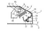
充電装置1の本体3は、側面視略三角形状の箱体からなり、その上部に開閉自在に支持された蓋体4が設けられている。蓋体4は、図1に示すように、手前側に向かって下側に傾斜した傾斜面に沿って形成された平面部4aと、その上端から所定長さだけ延出された延出部4bとを有している。被充電機器Pが載置されない状態のときには、本体3の上面は、蓋体4によって覆われることになり、異物などの本体3内への侵入を防止することができる。
【0029】
蓋体4の平面部4aの両側端には、平面部4aに対して直交方向に延びた支持片5がそれぞれ設けられている(図1では一方の支持片5のみを示す)。支持片5には、それに直交方向に立設した第1のボス6(第1の突起部材)、および第1のボス6から支持片5の延出方向に所定距離を隔てて立設した第2のボス7(第2の突起部材)が設けられている。また、蓋体4の平面部4aの表面には、被充電機器Pが載置されたときのその表面に対する衝撃を和らげるための緩衝部材8が設けられている。
【0030】
本体3の傾斜面下部には、蓋体4の先端が係止されるストッパ3aが形成されている。また、本体3内には、図3に示すように、蓋体4に対する被充電機器Pの押圧力に抗して蓋体4を閉塞状態に付勢する弾性部材としての圧縮ばね9が設けられている。なお、上記弾性部材としては、圧縮ばねに代えて板ばねなどでもよい。
【0031】
本体3の両側面の内側には、それらの両側面に沿ってそれぞれ配された側板部材10が設けられている。側板部材10には、その手前側の一側端から略水平方向に切り込まれつつ所定長さに形成された、上記第1のボス6を案内するための第1の案内孔11と、第1の案内孔11を囲むように略湾曲状に形成された、上記第2のボス7を案内するための第2の案内孔12とが設けられている。蓋体4は、第1および第2のボス6,7が第1および第2の案内孔11,12に支持されることにより、側板部材10によって支持されている。
【0032】
第2の案内孔12は、曲率半径が互いに異なる2つの円弧が連結された形状とされている。すなわち、第2の案内孔12は、空間上に設けられる仮想点Q(図4参照)を軸にしてその軸周りに第2のボス7が回転するように第2のボス7を案内する第1の円弧部13と、第1の案内孔11の終端位置に到達した第1のボス6(図5参照)を軸にしてその軸周りに第2のボス7が回転するように第2のボス7を案内する第2の円弧部14とを有している。別言すれば、第1の円弧部13は、図4に示す円弧R1に沿って形成されており、第2の円弧部14は、図5に示す円弧R2に沿って形成されている。
【0033】
図1に戻り、本体3には、被充電機器Pを収容するための収容部16が設けられている。収容部16には、載置板17が取り付けられている。載置板17は、被充電機器Pの底部と一部が当接される底板部18と、被充電機器Pが載置されたとき、被充電機器Pの背面が蓋体4を介して間接的に当接される背もたれ部19とを有している。底板部18は、奥行き方向に進むほど下側に傾斜しており、中央部分から若干屈曲されて傾斜が大となっている。すなわち、底板部18の中央部分から奥行方向に進む部分には、回転動作された蓋体4が底板部18に衝突しないように逃げ部としての空間スペースが形成されている。背もたれ部19は、底板部18に対して略直交方向に延びている。
【0034】
また、収容部16の底板部18には、複数の開口(図示せず)が形成されており、本体3には、この開口から出没可能な2つの端子部材21a,21b(以下、総称するときは「端子部材21」という)が設けられている。この端子部材21は、本体3に被充電機器Pが載置されたとき、被充電機器Pの底部に設けられた電極部Pc(図2参照)に接触するものである。たとえば、図2における左側の端子部材21aは、プラス側の端子部材とされ、図2における右側の端子部材21bは、マイナス側の端子部材とされている。
【0035】
端子部材21は、本体3に内装された、充電機能を実現するための種々の回路素子(図示略)が実装された回路基板22に接続されている。この回路基板22は、ファクシミリ装置2の内部に設けられたレギュレータ(図示略)に接続されている。レギュレータは、商用電源(交流電圧)を直流電圧に変換して上記回路基板22に供給するものである。すなわち、被充電機器Pがこの本体3に載置されたとき、上記端子部材21が被充電機器Pの電極部Pcに接触されることにより、レギュレータによって変換された直流電圧が回路基板22、端子部材21および電極部Pcを介して被充電機器Pに供給され、充電が行われる。
【0036】
端子部材21は、たとえば線細工ばねによって構成されており、回路基板22に当接支持されている。端子部材21は、一部が上方に突出した凸状に形成され、凸状部分の先端が被充電機器Pの電極部Pcと接触される。端子部材21は、通常状態で(本体3に被充電機器Pが載置されていない状態で)、収容部16の底板部18から上方に向けて突出しているが、本体3に被充電機器Pが載置されたとき、被充電機器Pの電極部Pcによって押圧され、本体3の内側に後退するようになっている。なお、端子部材21は、板ばねによって構成されていてもよい。
【0037】
次に、上記構成における作用について説明する。
【0038】
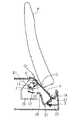
この充電装置1では、被充電機器Pが上方から蓋体4を押圧することにより、蓋体4を開放させ、その後、被充電機器Pが本体3に収容されるようになっている。まず、図1における被充電機器Pが載置されていない状態において、図4に示すように、被充電機器Pが蓋体4を上方から押圧すると、第2のボス7は、その押圧力に応じて第2の案内孔12の第1の円弧部13内を移動する。第2のボス7の移動によって、第1のボス6は、第1の案内孔11内における移動を開始する。すなわち、第2のボス7は、第1のボス6の移動開始を補助するように機能し、第1のボス6をよりスムーズかつ確実にスライド移動させることができる。
【0039】
次いで、第2のボス7が第1の円弧部13に沿って移動するとともに、第1のボス6が第1の案内孔11に沿って移動し、第1の案内孔11の終端部に到達する(図4参照)。このとき、第1のボス6は、蓋体4の退入動作の軸とされつつ、第1の案内孔11に沿ってスライド移動される。また、蓋体4は被充電機器Pによって上方から押圧されるため、蓋体4は、その先端が、図6に示すように、なだらかな曲線軌跡S1を描くように移動する。
【0040】
すなわち、従来の構成では、蓋体の回転軸が固定されていたために、蓋体が回転軸周りに回転すると、蓋体の先端が端子部材に衝突し、装置高さを長くせざるを得なかったが(図9,図10参照)、上記のように、蓋体4の回転軸に相当する第1のボス6を第1の案内孔11に沿ってスライド移動させながら、蓋体4を開放させることにより、蓋体4の先端が、図6に示すように、なだらかな曲線軌跡S1上を進行することになるため、蓋体4の先端が端子部材21に衝突するのを回避することができる。
【0041】
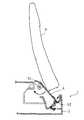
次いで、さらに被充電機器Pが蓋体4を押圧すると、図5に示すように、第2のボス7は、第1の案内孔11の終端部に到達した第1のボス6を軸としてその軸周りに第2の円弧部14内を移動する。そのため、蓋体4の先端は、図6に示すように、屈曲点Sを越えると、曲線軌跡S1とは異なる、なだらかな曲線軌跡S2上を進行することになる。
【0042】
そして、第2のボス7が第2の円弧部14の終端部に到達すると、蓋体4は、背もたれ部19に当接され、蓋体4の開放状態を維持する。また、被充電機器Pは、その底部が底板部18に接するとともに、その背面の一部が蓋体4と当接する。また、底部の電極部Pcが端子部材21と接触する。
【0043】
ここで、第2のボス7は、第1の案内孔11の終端に到達した第1のボス6を軸としてその軸周りに回転することにより、比較的小さな回転半径で回転することができる。すなわち、本体3の蓋体4による開放容積を小さくすることができ、つまり、被充電機器Pの載置スペースが必要以上に大きくならないようにすることができる。
【0044】
このように、被充電機器Pによって蓋体4が押圧されるとき、第1のボス6が蓋体4の退入動作の軸とされつつ、第1の案内孔11に沿ってスライド移動されることにより、蓋体4の先端がなだらかな曲線を描くようにして、すなわち、蓋体4の先端が端子部材21を回避するようにして蓋体4が開放動作する。したがって、装置高さを抑えながら、すなわち装置の小型化を図りながら、蓋体4を良好に開放させることができる。
【0045】
なお、被充電機器Pが載置された状態から再度、充電装置1から脱離したとき、圧縮ばね9(図3参照)の付勢力により、蓋体4は、本体3の上面を閉塞状態にさせる。
【0046】
図7は、蓋体4の変形例を示す図であるが、蓋体4の先端には、蓋体4の延出方向に延びるように端子部材21の汚れを除去するための除去部材としてのブラシ25が設けられていてもよい。このように、蓋体4の先端にブラシ25が設けられることにより、蓋体4が開閉動作するたびにブラシ25が端子部材21に触れることになり、端子部材21の汚れを除去することができるといった利点を有する。なお、除去部材としては、上記ブラシに限らず、たとえば綿製のものが適用されてもよい。
【0047】
なお、本願発明は、上記実施形態に限定されるものではない。たとえば、第1および第2のボス6,7、並びに第1および第2の案内孔11,12の配置位置は、本体3内における端子部材21の配置位置によって種々の位置に設計変更可能である。また、上記実施形態では、第1のボス6および第2のボス7は蓋体4側に、第1の案内孔11および第2の案内孔12は本体3側に、それぞれ設けられていたが、これに代えて、第1のボス6および第2のボス7は本体3側に、第1の案内孔11および第2の案内孔12は蓋体4側に、それぞれ設けられていてもよい。
【0048】
【発明の効果】
以上説明したように、請求項1に記載した発明の充電装置によれば、被充電機器によって蓋体が押圧されるとき、一方の案内部材が蓋体の退入動作の軸とされつつ、他方の案内部材と係合して相対移動される。そのため、たとえば固定された軸周りに蓋体が開放動作する場合に比べ、蓋体の先端がなだらかな曲線を描くようにして蓋体が開放動作することになるので、蓋体の先端が端子部材を回避するようにして蓋体が開放動作する。したがって、装置高さを抑えつつ、蓋体が良好に開閉する充電装置を提供することができる。
【0049】
また、請求項2に記載した発明の充電装置によれば、被充電機器によって蓋体が押圧されるとき、第1の突起部材が蓋体の退入動作の軸とされつつ、第1の案内孔に沿ってスライド移動される。そのため、たとえば固定された軸周りに蓋体が開放動作する場合に比べ、蓋体の先端がなだらかな曲線を描くようにして蓋体が開放動作することになるので、蓋体の先端が端子部材を回避するようにして蓋体が開放動作する。したがって、装置高さを抑えつつ、蓋体が良好に開閉する充電装置を提供することができる。
【0050】
また、請求項3に記載した発明の充電装置によれば、請求項2に記載の充電装置による効果に加え、被充電機器によって蓋体が押圧されるとき、第2の突起部材が第2の案内孔に沿って案内されることにより、第1の突起部材が第1の案内孔に沿ってスライド移動するときのその移動の開始を補助する。そのため、第1の突起部材をよりスムーズかつ確実にスライド移動させることができる。
【0051】
さらに、請求項4に記載した発明の充電装置によれば、請求項3に記載の充電装置による効果に加え、第2の突起部材が第1の円弧部を移動するとき、第2の突起部材によって第1の突起部材の第1の案内孔内におけるスライド移動の開始を補助することができる。また、第1の突起部材が第1の案内孔の終端部に到達したとき、すなわち、蓋体の先端が端子部材を回避するようにして蓋体が開放移動した後、第2の突起部材が第2の円弧部を移動するとき、第1の突起部材を軸にしてこの軸周りに第2の突起部材が回転移動する。これにより、第2の突起部材は、比較的小さな回転半径で回転することができ、本体内の蓋体による開放容積を小さくすることができる。そのため、被充電機器の載置スペースを十分に確保しながら、蓋体を回転動作させることができる。
【0052】
さらに、請求項5に記載した発明の充電装置によれば、請求項1ないし4のいずれかに記載の充電装置による効果に加え、蓋体の先端に端子部材の汚れを除去するための除去部材が設けられているため、蓋体が開閉動作するたびに除去部材が端子部材に触れることにより、端子部材の汚れを除去することができる。
【図面の簡単な説明】
【図1】本願発明に係る充電装置の側面透視図である。
【図2】図1の充電装置のA−A方向に見た要部断面透視図である。
【図3】充電装置の内部構成を示す側面透視図である。
【図4】被充電機器が蓋体を押圧するときの状態を示す充電装置の側面透視図である。
【図5】被充電機器が載置された後の状態を示す充電装置の側面透視図である。
【図6】充電装置の先端の移動軌跡を示す図である。
【図7】蓋体の変形例を示す図である。
【図8】従来の充電装置が適用されるファクシミリ装置の外観図である。
【図9】従来の、被充電機器が載置される前の状態を示す充電装置の側面透視図である。
【図10】従来の、被充電機器が蓋体を押圧するときの状態を示す充電装置の側面透視図である。
【符号の説明】
1 充電装置
2 ファクシミリ装置
3 本体
4 蓋体
6 第1のボス(第1の突起部材)
7 第2のボス(第2の突起部材)
11 第1の案内孔
12 第2の案内孔
21 端子部材
P 被充電機器[0001]
BACKGROUND OF THE INVENTION
The present invention relates to a charging device for charging a device to be charged, such as a mobile phone or a cordless child device, which can be operated by being charged.
[0002]
[Prior art]
2. Description of the Related Art Conventionally, telephones used in ordinary homes are often accompanied by a charged device such as a portable cordless handset. Such a device to be charged is portable, but when the user is not using it, it is mounted on a mounting table provided separately from the telephone main body or on a mounting base provided integrally with the telephone main body. Placed. In addition, since the device to be charged usually operates when the battery provided therein is charged, the above-mentioned mounting table also has a function as a charger for charging the device to be charged. There are many cases. That is, when the device to be charged is placed on the mounting table, charging is performed as necessary (see, for example, Patent Document 1).
[0003]
[Patent Document 1]
Japanese Unexamined Patent Publication No. 2000-14022
[0004]
In the charging device having such a mounting table, a terminal member for contacting the electrode portion of the device to be charged is provided. In this charging apparatus, if the terminal member is exposed to the outside, contact failure may occur between the terminal member and the electrode portion of the device to be charged due to, for example, contamination of the contact surface or formation of an oxide film. In order to suppress such inconveniences, for example, a charging device having a configuration in which a lid is provided so that the terminal member is not exposed to the outside when the device to be charged is not placed has been proposed.
[0005]
FIG. 8 is an external view when such a charging device is provided integrally with a facsimile machine. According to this
[0006]
[Problems to be solved by the invention]
In this
[0007]
For this reason, it is desirable to reduce the height of the
[0008]
In this case, it is conceivable to shorten the dimension of the
[0009]
This invention is proposed in view of said point, Comprising: It aims at providing the charging device which can open and close a cover body favorably, restraining apparatus height low.
[0010]
[Means for Solving the Problems]
In order to achieve the above object, a charging device according to a first aspect of the present invention includes a main body, a housing portion that is provided in the main body and houses a device to be charged that is operable by being charged, and the housing. Provided with a terminal member that protrudes so as to face the charged device to be accommodated, and a lid that is supported so as to retreat toward the inside of the main body and covers the upper surface of the main body, A charging device for opening the lid by pressing the lid from outside and charging the device to be charged accommodated in the accommodating portion via the terminal member, A first guide member formed on a support member extending in an orthogonal direction from both side ends of the lid, and provided along both side surfaces of the main body, engages with the first guide member and relatively moves. A side plate member having a second guide member and the lid; An elastic member that urges the lid in a closed state against the pressing force of the device to be charged against, when the lid is pressed toward the inside of the main body by the device to be charged, One guide member is used as an axis for the retracting operation of the lid, and is engaged with the other guide member and relatively moved so that the tip of the lid avoids the terminal member. The lid is configured to move. Here, when the projection member is applied as the first guide member, the guide hole is applied as the second guide member, and conversely, when the guide hole is applied as the first guide member, the second guide member is applied. A protruding member is applied as the guide member.
[0011]
According to such a charging apparatus, when the lid is pressed by the device to be charged, one guide member is engaged with the other guide member and is relatively moved while being used as the axis of the retracting operation of the lid. The For this reason, for example, compared to a case where the lid body opens around a fixed axis, the lid body performs an opening operation so that the tip of the lid body draws a gentle curve. Thus, the lid opens. Therefore, it is possible to provide a charging device in which the lid can be opened and closed satisfactorily while suppressing the device height.
[0012]
Further, the charging device of the invention described in claim 2 is provided with a main body, a housing portion that is provided in the main body and houses a device to be charged that is operable by being charged, and is provided in the housing portion. A terminal member protruding so as to face the device to be charged, and a lid body that is supported so as to retreat toward the inside of the main body and covers the upper surface of the main body, and the lid body from the outside The charging device for opening the lid by pressing and charging the device to be charged accommodated in the accommodating portion via the terminal member, the both ends of the lid A first projecting member formed on a support member extending in an orthogonal direction from the first and a first projecting member provided along both side surfaces of the main body and extending in a substantially horizontal direction for guiding the first projecting member. A side plate member having a guide hole and the lid An elastic member that urges the lid in a closed state against a pressing force of the device to be charged, and when the lid is pressed toward the inside of the main body by the device to be charged, The first projecting member is slid along the first guide hole while the first projecting member is used as the axis of the retracting operation of the lid so that the tip of the lid avoids the terminal member. The lid is configured to move.
[0013]
According to such a charging apparatus, when the lid is pressed by the device to be charged, the first projecting member is slid along the first guide hole while being used as the axis of the retracting operation of the lid. The For this reason, for example, compared to a case where the lid body opens around a fixed axis, the lid body performs an opening operation so that the tip of the lid body draws a gentle curve. Thus, the lid opens. Therefore, it is possible to provide a charging device in which the lid can be opened and closed satisfactorily while suppressing the height of the device.
[0014]
The charging device according to a third aspect of the present invention is the charging device according to the second aspect, wherein the support member is extended in a direction in which the support member extends from a position where the first protruding member is formed. A second projecting member is formed at a predetermined interval, and the side plate member is formed with a second guide hole extending in a substantially curved shape for guiding the first projecting member, When the lid is pressed toward the inside of the main body by the device to be charged, the second projecting member is guided along the second guide hole, whereby the first projecting member Assisting the start of sliding movement in the first guide hole.
[0015]
According to such a charging device, in addition to the effect of the charging device according to claim 2, when the lid is pressed by the device to be charged, the second projecting member is guided along the second guide hole. This assists the start of the movement when the first projecting member slides along the first guide hole. Therefore, the first projecting member can be slid and moved more smoothly and reliably.
[0016]
The charging device according to a fourth aspect of the present invention is the charging device according to the third aspect, wherein the second guide hole is formed when the lid body is pressed by the device to be charged. A first arc portion in which the two projecting members move, and a radius of curvature different from that of the first arc portion, and the first projecting member reaches the end portion of the first guide hole. And a second arc portion around which the second projecting member rotates about the first projecting member as an axis.
[0017]
According to such a charging device, in addition to the effect of the charging device according to
[0018]
A charging device according to a fifth aspect of the present invention is the charging device according to any one of the first to fourth aspects, wherein the end of the lid is removed to remove dirt on the terminal member. A member is provided.
[0019]
According to such a charging device, in addition to the effect of the charging device according to any one of
[0020]
DETAILED DESCRIPTION OF THE INVENTION
Hereinafter, preferred embodiments of the present invention will be described with reference to the accompanying drawings.
[0021]
FIG. 1 is a side perspective view of a main part of a charging device according to the present invention. 2 is a cross-sectional perspective view of a main part when the charging device shown in FIG. 1 is viewed in the AA direction. In the following description, FIG. 8 shown in the column of the prior art will be referred to again.
[0022]
As shown in FIG. 8, the charging
[0023]
The charging
[0024]
The charged device P includes, for example, a microcomputer (not shown) that controls the entire device, and a number key and a select key are provided on the surface of the charged device P as shown in FIG. , And other operation keys, and a display unit Pb made of, for example, a liquid crystal display panel for displaying an operation state, operation guidance, and the like. Moreover, as a to-be-charged apparatus charged with the charging
[0025]
The facsimile apparatus 2 is provided with a plurality of functions such as an inkjet printing function, an image reading function (scanner function), and an image communication function. For example, when transmitting facsimile data, the facsimile apparatus 2 reads an original using an image reading function, and transmits the read original data to a destination using a communication function. When the facsimile data is received by the communication function, the contents of the facsimile data are printed on a predetermined recording sheet using the printing function. The facsimile apparatus 2 can also be used as a printing apparatus or a scanner in an independent form connected to a personal computer, for example. Further, the printing function and the image reading function can be linked to use as a copier.
[0026]
As shown in FIG. 8, the facsimile apparatus 2 includes numeric keys, jog dial keys, and other operation keys, and is provided with an
[0027]
The facsimile apparatus 2 is a microcomputer in which RAM, ROM, NVRAM (Non-Volatile RAM) and the like are configured on a single chip mainly for a CPU that controls the overall operation of the facsimile apparatus 2, for example. (Not shown).
[0028]
The
[0029]
[0030]
At the lower part of the inclined surface of the
[0031]
Inside the both side surfaces of the
[0032]
The
[0033]
Returning to FIG. 1, the
[0034]
In addition, a plurality of openings (not shown) are formed in the
[0035]
The
[0036]
The
[0037]
Next, the operation of the above configuration will be described.
[0038]
In the
[0039]
Next, the
[0040]
That is, in the conventional configuration, since the rotation axis of the lid is fixed, when the lid rotates around the rotation axis, the tip of the lid collides with the terminal member, and the height of the device must be increased. However, as described above, the
[0041]
Next, when the to-be-charged device P further presses the
[0042]
When the
[0043]
Here, the
[0044]
As described above, when the
[0045]
Note that when the device to be charged P is detached from the charging
[0046]
FIG. 7 is a view showing a modified example of the
[0047]
In addition, this invention is not limited to the said embodiment. For example, the arrangement positions of the first and
[0048]
【The invention's effect】
As described above, according to the charging device of the first aspect of the present invention, when the lid is pressed by the device to be charged, the one guide member serves as the axis of the retracting operation of the lid, while the other It is engaged with the guide member and is relatively moved. For this reason, for example, compared to a case where the lid body opens around a fixed axis, the lid body performs an opening operation so that the tip of the lid body draws a gentle curve. Thus, the lid opens. Therefore, it is possible to provide a charging device in which the lid can be opened and closed satisfactorily while suppressing the height of the device.
[0049]
According to the charging device of the second aspect of the present invention, when the lid is pressed by the device to be charged, the first guide member is used as the axis of the retreat operation of the lid, while the first guide It is slid along the hole. For this reason, for example, compared to a case where the lid body opens around a fixed axis, the lid body performs an opening operation so that the tip of the lid body draws a gentle curve. Thus, the lid opens. Therefore, it is possible to provide a charging device in which the lid can be opened and closed satisfactorily while suppressing the height of the device.
[0050]
According to the charging device of the invention described in
[0051]
Furthermore, according to the charging device of the invention described in
[0052]
Furthermore, according to the charging device of the invention described in
[Brief description of the drawings]
FIG. 1 is a side perspective view of a charging device according to the present invention.
2 is a cross-sectional perspective view of a main part of the charging device of FIG. 1 as viewed in the AA direction.
FIG. 3 is a side perspective view showing the internal configuration of the charging device.
FIG. 4 is a side perspective view of the charging device showing a state when the device to be charged presses the lid.
FIG. 5 is a side perspective view of the charging device showing a state after the device to be charged is placed.
FIG. 6 is a diagram showing a movement trajectory of the tip of the charging device.
FIG. 7 is a view showing a modified example of the lid.
FIG. 8 is an external view of a facsimile machine to which a conventional charging device is applied.
FIG. 9 is a side perspective view of a conventional charging device showing a state before a device to be charged is placed.
FIG. 10 is a side perspective view of a conventional charging apparatus showing a state when a device to be charged presses a lid.
[Explanation of symbols]
1 Charging device
2 facsimile machines
3 Body
4 lid
6 First boss (first projecting member)
7 Second boss (second projecting member)
11 First guide hole
12 Second guide hole
21 Terminal material
P Charged equipment
Claims (5)
Translated fromJapanese前記本体の両側面に沿って設けられ、前記第1の案内部材と係合して相対移動する第2の案内部材を有する側板部材と、
前記蓋体に対する前記被充電機器の押圧力に抗して前記蓋体を閉塞状態に付勢する弾性部材と、を備え、
前記被充電機器によって前記蓋体が前記本体の内側に向けて押圧されるとき、一方の案内部材が前記蓋体の退入動作の軸とされつつ、他方の案内部材と係合して相対移動されることにより、前記蓋体の先端が前記端子部材を回避するようにして前記蓋体が移動するように構成されたことを特徴とする、充電装置。A main body, a housing portion that is provided in the main body and houses a charged device operable by being charged, and a terminal that is provided in the housing portion and protrudes so as to face the charged device to be housed A member and a lid that is supported so as to be retracted toward the inside of the main body and covers the upper surface of the main body, and by pressing the lid from outside, the lid is opened. A charging device for charging the device to be charged housed in the housing portion via the terminal member, wherein the first device is formed on a support member extending in an orthogonal direction from both side end portions of the lid body. A guide member,
A side plate member provided along both side surfaces of the main body and having a second guide member that engages with the first guide member and relatively moves;
An elastic member that urges the lid body in a closed state against a pressing force of the device to be charged against the lid body,
When the lid is pressed toward the inside of the main body by the device to be charged, one guide member is engaged with the other guide member while being used as a shaft for the retreat operation of the lid. Thus, the charging device is configured such that the lid moves so that the tip of the lid avoids the terminal member.
前記本体の両側面に沿って設けられ、前記第1の突起部材を案内するための略水平方向に延びた第1の案内孔を有する側板部材と、
前記蓋体に対する前記被充電機器の押圧力に抗して前記蓋体を閉塞状態に付勢する弾性部材と、を備え、
前記被充電機器によって前記蓋体が前記本体の内側に向けて押圧されるとき、前記第1の突起部材が前記蓋体の退入動作の軸とされつつ、前記第1の案内孔に沿ってスライド移動されることにより、前記蓋体の先端が前記端子部材を回避するようにして前記蓋体が移動するように構成されたことを特徴とする、充電装置。A main body, a housing portion that is provided in the main body and houses a charged device operable by being charged, and a terminal that is provided in the housing portion and protrudes so as to face the charged device to be housed A member and a lid that is supported so as to be retracted toward the inside of the main body and covers the upper surface of the main body, and by pressing the lid from outside, the lid is opened. A charging device for charging the device to be charged housed in the housing portion via the terminal member, wherein the first device is formed on a support member extending in an orthogonal direction from both side end portions of the lid body. A protruding member of
A side plate member provided along both side surfaces of the main body and having a first guide hole extending in a substantially horizontal direction for guiding the first projecting member;
An elastic member that urges the lid body in a closed state against a pressing force of the device to be charged against the lid body,
When the lid is pressed toward the inside of the main body by the device to be charged, the first projecting member is used as an axis for the retreating operation of the lid, and along the first guide hole. A charging device, wherein the lid is moved by sliding so that a tip of the lid avoids the terminal member.
前記側板部材には、前記第1の突起部材を案内するための略湾曲状に延びた第2の案内孔が形成されており、
前記被充電機器によって前記蓋体が前記本体の内側に向けて押圧される際、前記第2の突起部材が前記第2の案内孔に沿って案内されることにより、前記第1の突起部材の前記第1の案内孔におけるスライド移動の開始を補助する、請求項2に記載の充電装置。A second protrusion member is formed on the support member at a predetermined interval from the formation position of the first protrusion member in the extending direction of the support member.
The side plate member has a second guide hole extending in a substantially curved shape for guiding the first projecting member,
When the lid is pressed toward the inside of the main body by the device to be charged, the second projecting member is guided along the second guide hole, whereby the first projecting member The charging device according to claim 2, wherein the charging device assists the start of sliding movement in the first guide hole.
この第1の円弧部とは異なる曲率半径を有し、かつ前記第1の突起部材が前記第1の案内孔の終端部に到達したとき、その第1の突起部材を軸にしてこの軸周りに前記第2の突起部材が回転移動する第2の円弧部とを有する、請求項3に記載の充電装置。The second guide hole includes a first arc portion in which the second projecting member moves when the lid is pressed by the device to be charged;
When the first projecting member reaches the terminal end of the first guide hole when the first projecting member has a radius of curvature different from that of the first arc portion, the first projecting member is used as an axis around the axis. The charging device according to claim 3, further comprising: a second arc portion in which the second projecting member rotates.
Priority Applications (1)
| Application Number | Priority Date | Filing Date | Title |
|---|---|---|---|
| JP2002379012AJP3925407B2 (en) | 2002-12-27 | 2002-12-27 | Charger |
Applications Claiming Priority (1)
| Application Number | Priority Date | Filing Date | Title |
|---|---|---|---|
| JP2002379012AJP3925407B2 (en) | 2002-12-27 | 2002-12-27 | Charger |
Publications (2)
| Publication Number | Publication Date |
|---|---|
| JP2004215330A JP2004215330A (en) | 2004-07-29 |
| JP3925407B2true JP3925407B2 (en) | 2007-06-06 |
Family
ID=32815639
Family Applications (1)
| Application Number | Title | Priority Date | Filing Date |
|---|---|---|---|
| JP2002379012AExpired - Fee RelatedJP3925407B2 (en) | 2002-12-27 | 2002-12-27 | Charger |
Country Status (1)
| Country | Link |
|---|---|
| JP (1) | JP3925407B2 (en) |
Cited By (1)
| Publication number | Priority date | Publication date | Assignee | Title |
|---|---|---|---|---|
| US10772589B2 (en) | 2014-09-23 | 2020-09-15 | Samsung Electronics Co., Ltd. | Receiving device and X-ray imaging apparatus having the same |
Families Citing this family (7)
| Publication number | Priority date | Publication date | Assignee | Title |
|---|---|---|---|---|
| JP4842858B2 (en)* | 2007-03-01 | 2011-12-21 | パナソニック株式会社 | Electrical equipment connection device with dustproof function |
| JP5072690B2 (en)* | 2008-04-04 | 2012-11-14 | シャープ株式会社 | Contactless charger |
| US8541974B2 (en)* | 2009-09-17 | 2013-09-24 | Qualcomm Incorporated | Movable magnetically resonant antenna for wireless charging |
| JP5557046B2 (en)* | 2011-04-27 | 2014-07-23 | 株式会社Gsユアサ | Charger |
| KR101891043B1 (en)* | 2014-12-27 | 2018-08-22 | 후지츠 프론테크 가부시키가이샤 | Cradle and portable electronic apparatus set |
| JP7077977B2 (en)* | 2019-01-23 | 2022-05-31 | トヨタ自動車株式会社 | How to disconnect the charger, charging system and charging terminal |
| JPWO2022075427A1 (en)* | 2020-10-07 | 2022-04-14 |
- 2002
- 2002-12-27JPJP2002379012Apatent/JP3925407B2/ennot_activeExpired - Fee Related
Cited By (1)
| Publication number | Priority date | Publication date | Assignee | Title |
|---|---|---|---|---|
| US10772589B2 (en) | 2014-09-23 | 2020-09-15 | Samsung Electronics Co., Ltd. | Receiving device and X-ray imaging apparatus having the same |
Also Published As
| Publication number | Publication date |
|---|---|
| JP2004215330A (en) | 2004-07-29 |
Similar Documents
| Publication | Publication Date | Title |
|---|---|---|
| KR101006646B1 (en) | Portable terminal device | |
| EP1395030A1 (en) | Portable type information terminal device | |
| JP3925407B2 (en) | Charger | |
| JP2001007904A (en) | Electronic equipment with sliding lid | |
| US20080100262A1 (en) | Mobile terminal device | |
| JP4129003B2 (en) | Electronics | |
| KR20060003093A (en) | Electronics | |
| US8041408B2 (en) | Battery fastening apparatus and portable terminal using the same | |
| JP5414441B2 (en) | Information processing device | |
| US6203363B1 (en) | Electronic equipment with removable battery terminal | |
| JP3910507B2 (en) | Electronics | |
| JP4340088B2 (en) | Mobile device | |
| JP2010080209A (en) | Small-sized electronic device | |
| JPH08274678A (en) | Folding portable radio machine | |
| JP3223868B2 (en) | External connection structure of mobile phone | |
| JP4642005B2 (en) | Mobile terminal device | |
| JPH11112629A (en) | Portable information terminal | |
| JP4322356B2 (en) | Small electronic equipment | |
| JPH11111346A (en) | Charging device for portable electronic apparatus | |
| JPH09284368A (en) | Portable telephone set | |
| JPH01106658A (en) | electrical equipment | |
| JP2001242957A (en) | Mobile information processing system | |
| KR100617738B1 (en) | Wireless terminal device with charger | |
| JP4134970B2 (en) | Electronic device charger | |
| JPH08154342A (en) | Electric equipment charger |
Legal Events
| Date | Code | Title | Description |
|---|---|---|---|
| A621 | Written request for application examination | Free format text:JAPANESE INTERMEDIATE CODE: A621 Effective date:20051024 | |
| A977 | Report on retrieval | Free format text:JAPANESE INTERMEDIATE CODE: A971007 Effective date:20070126 | |
| TRDD | Decision of grant or rejection written | ||
| A01 | Written decision to grant a patent or to grant a registration (utility model) | Free format text:JAPANESE INTERMEDIATE CODE: A01 Effective date:20070206 | |
| A61 | First payment of annual fees (during grant procedure) | Free format text:JAPANESE INTERMEDIATE CODE: A61 Effective date:20070219 | |
| R150 | Certificate of patent or registration of utility model | Free format text:JAPANESE INTERMEDIATE CODE: R150 Ref document number:3925407 Country of ref document:JP Free format text:JAPANESE INTERMEDIATE CODE: R150 | |
| FPAY | Renewal fee payment (event date is renewal date of database) | Free format text:PAYMENT UNTIL: 20100309 Year of fee payment:3 | |
| FPAY | Renewal fee payment (event date is renewal date of database) | Free format text:PAYMENT UNTIL: 20110309 Year of fee payment:4 | |
| FPAY | Renewal fee payment (event date is renewal date of database) | Free format text:PAYMENT UNTIL: 20120309 Year of fee payment:5 | |
| FPAY | Renewal fee payment (event date is renewal date of database) | Free format text:PAYMENT UNTIL: 20120309 Year of fee payment:5 | |
| FPAY | Renewal fee payment (event date is renewal date of database) | Free format text:PAYMENT UNTIL: 20130309 Year of fee payment:6 | |
| FPAY | Renewal fee payment (event date is renewal date of database) | Free format text:PAYMENT UNTIL: 20130309 Year of fee payment:6 | |
| FPAY | Renewal fee payment (event date is renewal date of database) | Free format text:PAYMENT UNTIL: 20140309 Year of fee payment:7 | |
| LAPS | Cancellation because of no payment of annual fees |