JP3925071B2 - Hair removal equipment - Google Patents
Hair removal equipmentDownload PDFInfo
- Publication number
- JP3925071B2 JP3925071B2JP2000326976AJP2000326976AJP3925071B2JP 3925071 B2JP3925071 B2JP 3925071B2JP 2000326976 AJP2000326976 AJP 2000326976AJP 2000326976 AJP2000326976 AJP 2000326976AJP 3925071 B2JP3925071 B2JP 3925071B2
- Authority
- JP
- Japan
- Prior art keywords
- rotating cylinder
- hair removal
- cylinder
- spring
- rotary cylinder
- Prior art date
- Legal status (The legal status is an assumption and is not a legal conclusion. Google has not performed a legal analysis and makes no representation as to the accuracy of the status listed.)
- Expired - Fee Related
Links
- 210000004209hairAnatomy0.000titleclaimsabstractdescription77
- 210000000078clawAnatomy0.000claimsdescription71
- 230000002093peripheral effectEffects0.000claimsdescription11
- 238000003780insertionMethods0.000description6
- 230000037431insertionEffects0.000description6
- 230000035617depilationEffects0.000description4
- 230000005540biological transmissionEffects0.000description1
- 238000010276constructionMethods0.000description1
- 239000002537cosmeticSubstances0.000description1
- 230000000694effectsEffects0.000description1
- 239000002184metalSubstances0.000description1
- 230000000149penetrating effectEffects0.000description1
- 230000000630rising effectEffects0.000description1
Images


Classifications
- A—HUMAN NECESSITIES
- A45—HAND OR TRAVELLING ARTICLES
- A45D—HAIRDRESSING OR SHAVING EQUIPMENT; EQUIPMENT FOR COSMETICS OR COSMETIC TREATMENTS, e.g. FOR MANICURING OR PEDICURING
- A45D26/00—Hair-singeing apparatus; Apparatus for removing superfluous hair, e.g. tweezers
- A—HUMAN NECESSITIES
- A45—HAND OR TRAVELLING ARTICLES
- A45D—HAIRDRESSING OR SHAVING EQUIPMENT; EQUIPMENT FOR COSMETICS OR COSMETIC TREATMENTS, e.g. FOR MANICURING OR PEDICURING
- A45D26/00—Hair-singeing apparatus; Apparatus for removing superfluous hair, e.g. tweezers
- A45D26/0023—Hair-singeing apparatus; Apparatus for removing superfluous hair, e.g. tweezers with rotating clamping elements
- A45D26/0028—Hair-singeing apparatus; Apparatus for removing superfluous hair, e.g. tweezers with rotating clamping elements with rotating discs or blades
- A—HUMAN NECESSITIES
- A45—HAND OR TRAVELLING ARTICLES
- A45D—HAIRDRESSING OR SHAVING EQUIPMENT; EQUIPMENT FOR COSMETICS OR COSMETIC TREATMENTS, e.g. FOR MANICURING OR PEDICURING
- A45D26/00—Hair-singeing apparatus; Apparatus for removing superfluous hair, e.g. tweezers
- A45D2026/008—Details of apparatus for removing superfluous hair
- A45D2026/0085—Details of apparatus for removing superfluous hair with means for reducing noise
Landscapes
- Dry Shavers And Clippers (AREA)
- Hair Curling (AREA)
- Nitrogen Condensed Heterocyclic Rings (AREA)
- Nitrogen And Oxygen Or Sulfur-Condensed Heterocyclic Ring Systems (AREA)
- Saccharide Compounds (AREA)
Abstract
Description
Translated fromJapanese【0001】
【発明の属する技術分野】
本発明は、美容などの目的のために体毛を除去するのに使用される脱毛装置に関するものである。
【0002】
【従来の技術】
従来から、回転シリンダーの回転駆動に伴って毛を挟持するとともに引き抜く脱毛装置が特開平6−121708号公報や特開2000−125925号公報により知られている。
【0003】
特開平6−121708号公報には回転して毛を引き抜く回転シリンダーに相対移動可能な締め付け要素を設けるとともに、移動可能な締め付け要素を作動するための作動要素は押し付け力から開放された時、ばねにより回転軸の中央に対して反対する方向へと移動し、締め付け要素を移動させる。
【0004】
また特開2000−125925号公報には開閉板の中央の凸部を支点とする揺動で開閉レバーを軸方向に摺動させて脱毛用の爪を開閉するものが示されている。このものでは、開閉レバーを摺動させる部材である開閉板が回転シリンダーの両側面部に取り付けられ、その開閉板は回転シリンダーの各片側で夫々一体の部品となっている。
【0005】
【発明が解決しようとする課題】
前者の公報に示されたものでは、組み立てに際して、一対の相対する作動要素間にばねを設置しなければならないために組立が困難であるという問題を有している。また脱毛効率を良くするため回転シリンダー表面に複数の爪列を配置する時、配置する爪列の数だけのばねを必要とするため、多くのばねが必要となり高価になってしまうという問題を有している。
【0006】
後者の公報に示されたものでは、脱毛効率を高めるために回転シリンダーの円周表面上に多くの脱毛爪列を設けようとしても、回転シリンダーの表面に3列以上の脱毛爪列を配置することができないという問題を有している。
【0007】
本発明は上記の点に鑑みてなされたものであり、その目的とするところは組立性が良く安価な脱毛装置を提供することにあり、また回転シリンダーの円周表面上に多数列の脱毛爪列を設けることにも容易に対応することができる脱毛装置を提供することにある。
【0008】
【課題を解決するための手段】
上記課題を解決するために本発明に係る脱毛装置は、軸回りに回転駆動される回転シリンダーと、この回転シリンダーの外周面に配されているとともに回転シリンダーの上記回転に伴って開閉されて閉時に毛を挟持し且つ回転シリンダーの回転で挟持した毛を引き抜く脱毛手段とを備えている脱毛装置において、上記脱毛手段は上記回転シリンダーに固定された複数の固定爪と、回転シリンダーの軸方向に可動で各固定爪に対して開閉動作を行う複数の可動爪とからなる脱毛爪で形成されており、上記回転シリンダー内にはその軸方向動作で上記可動爪を駆動する複数個の開閉レバーが配されており、回転シリンダーの周方向において並んでいる上記複数個の開閉レバーは、回転シリンダーの軸方向端部に配された復帰ばねが備える複数のばね片で夫々回転シリンダーの軸方向に付勢されていることに特徴を有している。
【0009】
このために一つ、または開閉レバーの数より少ないばねで複数の開閉レバーの復帰を行わせることができる。
【0010】
上記複数個の開閉レバーは、その一端が回転シリンダーの軸方向端面に位置しているとともに回転シリンダーの内周側と外周側とに交互に配された上記開閉レバーの上記一端は、内周側の開閉レバーと隣接する外周側の開閉レバーとが周方向において重なって配置されており、上記復帰ばねにおける各ばね片は隣接する複数の開閉レバーに接して付勢しているものであることが望ましい。
【0011】
また開閉レバーを付勢する復帰ばねは板ばねより形成することが、ばね形状の自由度の点で好ましい。
【0012】
この場合、復帰ばねは回転シリンダーの周方向に等間隔で配置された複数のばね片を備えたものを用いるのが好ましく、また、ばね片は略コ字状の形状をしていると、単純に半径方向へ伸びるばね片よりもばねの有効長さを長く取ることができる。さらにばね片は根元から先端へ螺旋状に曲げられているものとすれば、さらにばねの有効長さを長くとることができる。
【0013】
そして、この復帰ばねは中央に孔を備えて、この孔で回転シリンダーに取り付け位置決めされるものとすることで、組立性を高めることができる。
【0014】
【発明の実施の形態】
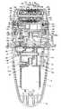
以下、図に示す実施形態の一例に基づいて説明すると、図示例の脱毛装置は手で把持することができるサイズに形成しているとともに駆動源であるモータ3を内蔵している本体ハウジング1上に回転シリンダー4を備えた脱毛ヘッド2を設けたもので、回転シリンダー4には開閉して毛を挟持する脱毛爪で構成した脱毛手段を設けており、回転シリンダー4の軸回り回転に伴って脱毛手段が毛を挟持して引き抜くものとなっている。
【0015】
前面にスイッチSが配されている本体ハウジング1は図7及び図8に示すように前後に2つ割りした半割ケーシング7,7をビス7nにより接合したもので、上端開口部はモータ3や駆動伝達手段を保持して本体ハウジング1内に納められた基台8の上面部で閉じられており、本体ハウジング1の下端には給電用のプラグ9を備えている。なお、本体ハウジング1に電源である電池を内蔵したものであってもよい。
【0016】
上面部にフック連結部10を備えている上記基台8は、モータ内装用基台12とこれの側方開口部にビス131nで固定されるカバー13とからなるもので、モータ内装用基台12の下部のモータ内装部12aに下方からモータ3が嵌め込まれている。そして、カバー13で側方開口部が覆われたモータ内装用基台12の上部内の空間16には過負荷クラッチ18及びギア19が納められており、半割ケーシング7,7内の突起7d,7e間にモータ内装用基台12の支持枠25が嵌め込まれることで本体ハウジング1の内部に配されている。
【0017】
基台8に軸18jで取り付けられた過負荷クラッチ18は、図13に示すように、フェース歯車181と小歯車180とクラッチばね182とからなるもので、小歯車180はその一端部に、嵌め込み部180aと鍔部180bとを備えているとともに、嵌め込み部180aの端面に位置決め突起180cとねじ螺合孔180dとを備えている。フェース歯車181は小歯車180の嵌め込み部180aが回転自在にはめ込まれる孔181aを備えたもので、孔181aの周囲には溝型の係止部181bを放射状に複数個形成してある。
【0018】
クラッチばね182は、周囲の複数箇所からばねアーム片182aを回転方向と反対方向に連出した板ばねであり、中央部には位置決め孔182cとねじ挿入孔182dを備えており、各ばねアーム片182aの先端部には係合突起182bを備えている。
【0019】
小歯車180の嵌め込み部180aをフェース歯車181の孔181aに回転自在にはめ込むとともに鍔部180bを孔181aの外方においてフェース歯車181の外面に当接させ、この状態で、嵌め込み部180aの端面の位置決め突起180cに板ばね182の位置決め孔182cを嵌め込んで位置決めし、ねじ挿入孔182dからねじ183を挿入して小歯車180のねじ螺合孔180dに螺合することでクラッチばね182を小歯車180に取り付けて、クラッチばね182の係合突起182bを係止部181bに弾性的に係止すれば、フェース歯車181に伝達された回転は、クラッチばね182を介して小歯車180に伝達される。そして、ある設定されたトルク以上の動力が伝達されたときには、クラッチばね182に設けた係合突起182dが係止部181bから外れて、小歯車180に対してフェース歯車181が空回りするものであり、このために、ギアに毛を挟んだり、異物をかみ込んでロックしたときにモータ3のトルクを途中で遮断することができて、駆動伝達部の損傷を防止できるものである。
【0020】
モータ内装部12aに装着されたモータ3の出力軸3aは、モータ内装用基台12の孔12bを通じて空間16内に位置し、この部分にピニオン17が固着され、該ピニオン17が上記フェース歯車181に噛み合っている。また、軸19jにより軸支されて基台8の上面部に臨んでいるギア19は、上記小歯車180と噛み合っている。従ってモータ3の回転は、ピニオン17及び過負荷クラッチ18を介してギア19に伝達され、このギア19を通じて後述の脱毛ヘッド2の回転シリンダー4の駆動などが行われる。
【0021】
基台8の上面のフック連結部10は、モータ内装用基台12の上面部中央部に設けたトンネル用突部10aと、一対のスライド枠26,26とからなるもので、トンネル通路を有しているトンネル用突部10aの上面部には孔15bを設けてある。
【0022】
平面視略矩形をした各スライド枠26は、その外側片部から外側方に向けて操作部26aを突設し、内側片部の内面に支持フック261bを突設し、内側片部の上方にストッパ用突部26bを上方に向けて突出したもので、トンネル用突部10aのトンネル通路内にスライド自在にはめ込むとともにストッパ用突部26bを孔15b内にスライド自在に係合させることで、トンネル用突部10aに装着される。ストッパ用突部26bが孔15bの縁に当たることで抜け止めされた一対のスライド枠26,26間には、トンネル通路内においてスプリング26dを介装してあり、該スプリング26dによって両スライド枠26,26は外側に向けて弾性付勢される。そして両スライド枠26の操作部26aは本体ハウジング1に設けた孔7fを通じて本体ハウジング1の外側方に突出する。
【0023】
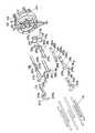
次に基台ブロック15と脱毛ブロック24とからなる脱毛ヘッド2について説明すると、脱毛ブロック24は、図10及び図11に示すように、脱毛手段を備えた回転シリンダー4と、この回転シリンダー4を支持するシリンダー取り付け基台27及びシリンダーカバー28と、カム29、保持ばね30、ヘッドフレーム31、そして図9に示すベース300とからなる。
【0024】
シリンダー取り付け基台27とその一端部に取り付けられるシリンダーカバー28とは、それぞれから上方に向けて突出させた突出支持部27a,28aに設けている軸孔部28bによって、回転シリンダー4に挿通されている軸4bの両端部を支持することで、回転シリンダー4をその軸回りに回転自在に保持しているもので、上記突出支持部27a,28aにはそれぞれ角孔状をしたカム挿入孔27c,28cと、カム挿入孔27c,28cの上下縁部に位置する軸支持溝27d,28dとを形成してある。そして、ローラ型のカム29をそれぞれカム挿入孔27c,28cに嵌め込むとともに、各カム29に挿入したローラ軸29aの上下両端部を軸支持溝27d,28dに嵌め込んで、カム29を水平回転自在に支持している。なお、カム29の一部はカム挿入孔27c,28cから内側に突出している。
【0025】
また、突出支持部27a,28aの外側には保持ばね30を取り付けてある。保持ばね30は、基部の孔30aに挿通するビス301でシリンダー取り付け基台27とシリンダーカバー28に固定したもので、その上部には孔部30bを備えており、この孔部30bの上下縁部で上記ローラ軸29aの上下両端を弾性的に押圧している。孔部30bはカム29に対応させたもので、カム29が保持ばね30に接触することがないようにしている。
【0026】
ベース300の上面にビス301で固定されているシリンダー取り付け基台27とシリンダーカバー28の両端外面には、ばね280によって外側へ付勢された釦281を配設してある。この釦281は、フレーム31を着脱するためのフック281aを備えたものであり、釦281を押し込めばフック281aがフレーム31のフック掛かリ部31aから外れて、フレーム31を取り外すことができる。
【0027】
また、シリンダー取り付け基台27のシリンダーカバー28側には凹欠部27iを設けて、ここに駆動用歯車40を配置してある。両端部がシリンダー取り付け基台27とシリンダーカバー28とで軸支される軸40jで支持された該駆動用歯車40は、回転シリンダー4が備えるギア41gと噛合するとともに、基台ブロック15が備えるギア15cと噛合する。
【0028】
基台ブロック15は図9及び図12に示すように、基台ブロックカバー155に内装された基台本体15aと、基台本体15aの外周を囲む基台カバー155と、基台本体15aの上方に開口した凹所15h内に配したギア15c及び歯車15eとからなるもので、上下方向の軸15fによって支持された歯車15eは、水平方向の軸105jによって支持されたギア15cが備えているフェースギア部に噛み合うもので、偏芯カム15gを一体に備えている。
【0029】
脱毛ブロック24は、この基台ブロック15上に配設されるものであり、脱毛ブロック24のベース300の下面に設けられて上記凹所15h内に位置するリブ27Aが備える孔27Abに基台本体15aを貫通するスライドガイド軸15jを挿通することで、ベース300を、つまりは脱毛ブロック24をスライドガイド軸15jの軸方向にスライド自在に装着している。
【0030】
また、各リブ27Aに設けたばね受け27Aaと凹所15hの両端部内面との間にばね15k,15kを夫々介装してあり、このために脱毛ブロック24は基台ブロック15に対して回転シリンダー4の軸方向に往復移動自在となっているとともに、両方のばね15kによるばね付勢で脱毛ブロック24は基台ブロック15の中央に位置するようにしてある。
【0031】
また、ベース300の下面の中央には凹部27Bを設けているが、この凹部27Bに偏芯カム15gが係合する。偏芯カム15gが偏芯回転する時、偏芯カム15gは凹部27Bの内側面を押してばね15kのばね力に抗して基台ブロック15を往復動させるものであり、このために凹部27Bの回転シリンダー4の回転軸と直交する方向の巾は偏芯カム15gの偏芯量の倍以上として回転軸と直交する方向には移動しないようにしてある。
【0032】
ここで、偏芯カム15gの回転により周期的に往復動する脱毛ブロック24を付勢している両側のばね15k,15kは、往復運動の端点での慣性力を吸収するものであり、衝突を防いで衝突音等の騒音を小さくする。
【0033】
このように、基台ブロック15に対して回転シリンダー4の軸方向に脱毛ブロック24を往復移動自在に取り付けている脱毛ヘッド2は、基台ブロック15の基台本体15aの下面に設けたフック11,11を本体ハウジング1のフック連結部10に連結することで本体ハウジング1に取り付けられる。この取り付けは、操作部26aを押した状態で脱毛ヘッド2の下面の一対のフック11をそれぞれ両スライド枠26の矩形状をした開口内に嵌め込み,この状態で操作部26aの押圧を解除することでスプリング26dのばね力により両スライド枠26が外側に移動して支持フック261bを上記フック11に係止することでなされるものであり、このように脱毛ヘッド2を本体ハウジング1に対して取り付けた状態では歯車19がギア15cに噛み合うことになる。脱毛ヘッド2を取り外すに当たっては、上記と逆に操作部26aを押すことで支持フック261bをフック11から外すことができるので、この状態で脱毛ヘッド2を引き離せばよい。
【0034】
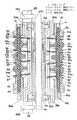
次に脱毛ブロック24における回転シリンダー4について説明すると、この回転シリンダー4は図15及び図16に示すように、一対の略円筒部材41a,41bを軸方向に連結することで形成されたもので、その外周面には周方向に複数箇所(図示例では45°の間隔を置いて8箇所)の凹部4aを備えて、各凹部4a内に脱毛用主体ユニット32が嵌め込まれている。
【0035】
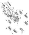
ここにおける脱毛用主体ユニット32は、図17に示すように、支点板33と、複数(図示例では4枚)の可動爪5a,6aと、支点止め部材34,35と、固定爪36,37とからなるもので、この固定爪36,37は、それぞれ2枚を一組として一体に形成したものとなっている。
【0036】
支点板33は支点止め部材34,35の嵌め込み用の角孔33a,33bと、可動爪嵌め込み用の角孔33cとを備えており、支点止め部材34,35の下面に設けた突起34a,35aを固定爪36,37に設けた孔36a,37aを通じて、支点板33の角孔33a,33bに圧入固定することで、固定爪36,37の固定も同時に行う。固定爪36,37を2つ1組とすることで組立を簡単にしているものであり、特に回転シリンダー4の周方向に脱毛用主体ユニット32を複数配置する場合、回転軸と直交する長さを小さくすることができるために、回転シリンダー4の外径も小さくすることができる。
【0037】
可動爪5a,6aは両端の突起5b,6bを支点止め部材34,35の両端に設けたリブ34c,35cにフック係合することで固定爪36,37の脇に組み付けられる。この時、2枚1組が一体に形成された固定爪36,37に対して、可動爪5a,6aは1枚ずつ独立したものを用いるとともに、一体となっている2枚の固定爪36,37に対しては、同じ側に可動爪5a,6aが位置するように、1枚の可動爪5a,6aは固定爪36,37の孔36a,37a内に位置させる。
【0038】
上記のように一つのユニットとして組み立てられた脱毛用主体ユニット32は、回転シリンダー4の各凹部4aに嵌め込むとともに、凹部4aの一方の端に設けた孔4bから挿入した軸41を,支点止め部材34,35の孔34d,35dと4枚の可動爪5a,6aの各孔5a1,6a1とに挿通して、該軸41の先端部を他端の回転シリンダー41bの孔4b1に嵌め込むことで、凹部4aに装着される。
【0039】
また、回転シリンダー4における一方の回転シリンダー41aの軸方向の端面には図15に示すように周方向に複数の孔4cを形成して、これらに開閉レバー38a,38b,38c,38dと開閉レバー39a,39b,39c,39dとを周方向において交互に挿入してある。なお、開閉レバー38a,38b,38c,38dの端部の押圧部381a,381b,381c,381dは、開閉レバー39a,39b,39c,39dの端部の押圧部391a,391b,391c,391dよりも回転シリンダー4の内周側に位置している上に、周方向において両端部がそれぞれ押圧部391a,391b,391c,391dの端部と重なるようにしてある。また、他端の回転シリンダー41bにも図16に示すように複数の孔4cを周方向に設けて、開閉レバー39a,39b,39c,39dと開閉レバー38a,38b,38c,38dとを前述と同様に交互に挿入してある。
【0040】
そして、各開閉レバー38a,38b,38c,38d,39a,39b,39c,39dには、回転シリンダー4の各凹部4aに脱毛用主体ユニット32を装着した時、可動爪5a,6aの突片5c,6cが係合することになる溝382a,382b,382c,382d,392a,392b,392c,392dを設けてある。このとき、回転シリンダー41a側から挿入した開閉レバーは可動爪6aの突片6cと係合し、回転シリンダー41b側から挿入した開閉レバーは可動爪5aの突片5cと係合する。
【0041】
また、回転シリンダー4の軸方向の両端面と開閉レバー38a,38b,38c,38d,39a,39b,39c,39dの押圧部との間には、板ばねで形成した復帰ばね370を配置してある。回転シリンダー41a,41bの中心部に設けた突起4dと係合する位置決め用の孔を中心部に備えた上記復帰ばね370は、図15,16及び図18に示すように、略コ字状をした4本のばね片370aを一体に備えて、これらばね片370aが開閉レバー38a,38b,38c,38d,39a,39b,39c,39dを回転シリンダー4の軸方向外側に向けて付勢している。
【0042】
ばね片380aを略コ字状とすることでばねの有効長さを大きくしているために、開閉レバーを前記カム29で押圧する際のばね反力を小さくすることができて低負荷で効率の良い回転シリンダー4とすることができるものであり、またばね片370aは根元から先端にかけて開閉レバー側に螺旋状に曲げており、このために開閉レバーの移動量を大きくとることができて、可動爪5a,6aの固定爪36,37に対しての開き量も大きくすることができる。
【0043】
ここで、一つのばね片370aは、隣り合う2つの開閉レバー38b,39dを外側に押し、またばね片370aは開閉レバー38c,39aを押すものであり、このために4本のばね片370aを一体に有している復帰ばね370で、組み込まれた全ての開閉レバー38a,38b,38c,38d,39a,39b,39c,39dを外側へ付勢している。
【0044】
そして、開閉レバーを外側から押す力が作用しないとき、可動爪5a,6aはその突片5c,6cが外側に押されることで支点板33の角孔33cの孔縁を支点として回動して支点止め部材34に位置決めされた固定爪37,36から離れ、また、開閉レバーの押圧部381a,381b,381c,381d,391a,391b,391c,391dに外側から外力が加わると、可動爪5a,6aはその突片5c,6cが内側に押されることで支点板33の角孔33cの孔縁を支点として回動して固定爪36,37に押し当てられる。このように、回転シリンダー4の軸方向端面に板ばねからなる復帰ばね370を配置して、全ての開閉レバーを復帰ばね370で外側へ付勢しているために、組立易く且つ安価な回転シリンダー4を得ることができるものとなっている。
【0045】
ここにおいて、脱毛用主体ユニット32は、2組4枚の固定爪36,37と4枚の可動爪5a,6aとによって、毛を挟持(把持)して引き抜くための脱毛爪を都合4個備えたものとなっているのであるが、2組4枚の固定爪36,37は図1及び図19から明らかなように回転シリンダー4の軸方向において等間隔となるようにしていることから、毛を挟持する際の位置のバランスが良くて脱毛効率が高くなっており、また回転シリンダー4の周方向に設けた各爪列の脱毛爪の毛の把持位置が等間隔になっているので、狙った毛が抜き易くて脱毛効率の良い回転シリンダー4とすることができる。
【0046】
また、ここで示した構成のものは、開閉レバーの移動で総計4個の可動爪5a,6aを固定爪36,37に対して同時に接近・離間させることができるものの、部品構成が簡単であり、組み立て性も良好である。
【0047】
さらに、2枚で一組となっている各固定爪36,37はそれぞれ同じ開閉レバーに係合する可動爪5a,6aとの間で開閉動作を行うが、各固定爪36,37は弾性部36b,37b(図17参照)をそれぞれ備えており、このために可動爪5a,6aが固定爪36,37に押圧される際の毛の把持強度の部品精度によるばらつきが少なくなっている。すなわち、可動爪6aの一方の把持強度が強くても、固定爪36が押圧方向において弾性変形することで、他方の可動爪6aの把持強度と釣り合わせるものであり、この結果、毛の抜き残しが無くて脱毛効率が良いものとなっている。このとき、2個一組の固定爪36,37をばね性のある金属部品で形成すると、安価である上に毛の把持も確実なものとすることができる。
【0048】
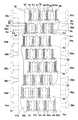
加えるに、回転シリンダー4に設けた各凹部4aは、軸方向において全てずれた位置に設けているために、凸部4aに嵌め込んだ脱毛用主体ユニット32も軸方向において全てずれた位置に配設されており、このために図20に示すように脱毛爪(開閉される固定爪36,37と可動爪5a,6aとの対)も、周方向において一直線上に並ぶのではなく、軸方向にずれた位置にある。この状態で、前述のごとく1回転での把持位置が等間隔となっているため、抜き残しのない脱毛効率の良い回転シリンダー4とすることができる。
【0049】
なお、上記支点止め部材34,35は皮膚保護部材としての役割を持たせるためにその上面部に、可動爪5a,6a及び固定爪36,37が直接肌に当たることを防ぐ半円形状の円弧部34b,35bを備えている。可動爪5a,6a及び固定爪36,37が直接肌に当たって生じる肌の削れ等を防止しているものである。
【0050】
以上のように構成された図示例の脱毛装置においては、脱毛ヘッド2を本体ハウジング1に取り付けた状態でモータ3を駆動すれば、前述のように過負荷クラッチ18と歯車19とを介してギア15cに回転が伝達され、さらにギア15cの回転が駆動用歯車40を介してギア41gに伝達されて回転シリンダー4が回転する。
【0051】
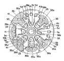
回転シリンダー4が回転して、図1に示すようにカム29の位置にきた開閉レバー38a,38b,38c,38d,39a,39b,39c,39dは、カム29に押されて復帰ばね370aに抗して内側に押され、開閉レバーが可動爪5a,6aの下部の突片5c,6cを内側に押す。
【0052】
下端部が内側に押されて回転する4枚の可動爪5a,6aは、それぞれ固定爪36,37に押し当たるものであり、可動爪5a,6aと固定爪36,37との間に導入された毛は挟持される。そして、この毛を挟持した状態で回転シリンダー4がさらに回転することで毛が引き抜かれる。また、回転シリンダー4の回転により次の開閉レバーがカム29の所に至ってカム29により押圧され、上記と同様に毛を挟持して引き抜く。
【0053】
ここで、図14と図17と図20に示すように、固定爪36,37の回転方向先端部36c,37cは軸方向で外側に曲げられており、可動爪5a,6aの回転方向先端部5d,6dは固定爪36,37の先端部36c,37cとは対称に曲げられているため、特に長い毛を挟持部へと導入しやすくなっており、導入効率が高く、毛の抜き残しが少なくなっている。
【0054】
また、図23に示すように、可動爪5a,6aの先端部5d,6dと固定爪36,37の先端部36c,37cはその外周縁の曲率半径を回転シリンダー4の回転半径Raよりも小さくしてあり、押し付け過ぎたりした場合においても、可動爪5a,6aの先端部5d,6dと固定爪36,37の先端部36c,37cによる肌の削れ等を防止することができ、このため肌当たりが良く安全性の高いものとなっている。
【0055】
また、図22に示すように、支点止め部材34,35の皮膚保護部材としての役割を果たしている円弧部34b,35bの曲率半径も、回転シリンダー4の回転半径Raよりも小さい径Rbとしてその中心を回転シリンダー4の中心より外周側にずらすことで、肌面に対し点又は線接触となるようにしており、これにより肌と回転シリンダー4との摩擦抵抗を小さくして、押し付け過ぎでトルクが上がることによる回転数の低下や、肌との接触摩擦による肌のめくれ等を防止している。
【0056】
さらに、図14に示すように,周方向に1つ置きに設けた開閉レバー38a,38b,38c,38dの押圧部381a,381b,381c,381dの両端部が開閉レバー39a,39b,39c,39dの押圧部391a,391b,391c,391dの端部と周方向において重なっていることから、毛を挟持するのに寄与した開閉レバーの押圧部の回転方向の後端部をカム29が押圧しているとき、次の開閉レバーの押圧部の前端部もカム29で同時に押圧するものであり、このため、爪5a,6a,36,37を回転シリンダー4の周方向に複数配置しているにもかかわらず、毛を挟時して引き抜く距離が長くなっている。
【0057】
また、開閉レバー38a,38b,38c,38dの押圧部381a,381b,381c,381dと開閉レバー39a,39b,39c,39dの押圧部391a,391b,391c,391dの回転方向の両端には、斜面388a,399aを設けて、隣り合う開閉レバーの斜面388a,399aを交差させているために、負荷変動を抑えることができ、回転シリンダー4の回転による騒音も抑えることができるものとなっている。
【0058】
加えるに、回転シリンダー4が回転して脱毛を行っている時、ギア15cから歯車15eにも回転が伝達されて偏心カム15gが回転し、この回転で前述のように脱毛ブロック24が基台ブロック15に対して回転シリンダー4の軸方向に周期的に往復移動する。
【0059】
この往復移動により、脱毛ブロック24の回転シリンダー4に設けた固定爪36,37と可動爪5a,6aとによる毛の挟持位置が変化するために、肌の全面の毛を抜くことができるものである。
【0060】
この時、偏芯カム15gと一体の歯車15eの減速比を回転シリンダー4に至る減速比よりも小さくして、回転シリンダー4の回転周期よりも移動周期を大きくすることにより、挟持位置を増やすことができて、更に脱毛効率を上げることができる。
【0061】
【発明の効果】
上記のように請求項1記載の発明にあっては、一つ、または開閉レバーの数より少ないばねで複数の開閉レバーの復帰を行わせることができるものであり、多数の復帰ばねを組み込む場合に比して、はるかに組立性が良いく、安価な脱毛装置とすることができる。
【0062】
また、請求項2記載の発明にあっては、開閉レバーの数だけばね部を必要としない上に、組み立てやすくなるものであり、しかも内周側の開閉レバーと隣接する外周側の開閉レバーとが周方向において重なって配置されて、上記復帰ばねにおける各ばね片は隣接する複数の開閉レバーに接して付勢しているために、複数の開閉レバーを付勢するとはいえ、復帰ばねの形状は簡単なものでよく、復帰ばねの数が少なくてすむこともあって、安価な脱毛装置とすることができる。
【0063】
また開閉レバーを付勢する復帰ばねは板ばねで形成することで、ばね形状の自由度が高いために、複数の開閉レバーを一体で付勢することが容易であり、安価で組立性も容易な脱毛装置とすることができる。
【0064】
特に板ばねである復帰ばねは回転シリンダーの周方向に等間隔で配置された複数のばね片を備えたものを用いることで、開閉レバーへ加える力は全ての開閉レバーに対してほぼ均等に与えることができて、脱毛用の爪の開き量を等しくすることができる。
【0065】
また、ばね片は略コ字状の形状をしていると、単純に半径方向へ伸びるばね片よりもばねの有効長さを長く取ることができることから、ばね負荷に抗して開閉レバーを駆動して脱毛用の爪を開閉する際の荷重を小さくすることができ、低定負荷で効率の良い脱毛装置とすることができる。
【0066】
さらにばね片は根元から先端へ螺旋状に曲げられているものとすれば、さらにばねの有効長さを長くとることができ、必要なばねの振幅量を有しつつ、荷重を小さくすることができ、低負荷で効率の良い脱毛装置とすることができる。
【0067】
そして、この復帰ばねは中央に孔を備えて、この孔で回転シリンダーに取り付け位置決めされるものとすることで、組立性をさらに高めることができる。
【図面の簡単な説明】
【図1】本発明の実施の形態の一例における回転シリンダーの断面図である。
【図2】同上の全体構成を示す正面図である。
【図3】同上の平面図である。
【図4】同上の縦断面図である。
【図5】同上の横断面図である。
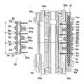
【図6】同上の脱毛ヘッドの縦断面図である。
【図7】同上の本体ハウジングの分解斜視図である。
【図8】同上の本体ハウジング内の部品の分解斜視図である。
【図9】同上の基台ブロック及びベースの分解斜視図である。
【図10】同上の脱毛ブロックの分解斜視図である。
【図11】同上の脱毛ブロックの他の部品の分解斜視図である。
【図12】同上の基台ブロックの基台本体の斜視図である。
【図13】同上の過負荷クラッチの分解斜視図である。
【図14】同上の回転シリンダーの斜視図である。
【図15】同上の回転シリンダーの分解斜視図である。
【図16】同上の回転シリンダーの分解斜視図である。
【図17】同上の脱毛主体ユニットの分解斜視図である。
【図18】同上の開閉レバーと復帰ばねの組立状態を示す斜視図である。
【図19】同上の回転シリンダーの分解縦断面図である。
【図20】同上の回転シリンダー表面の展開図である。
【図21】同上の回転シリンダーの横断面図である。
【図22】同上の回転シリンダーの部分拡大図である。
【図23】同上の回転シリンダーの部分拡大図である。
【符号の説明】
4 回転シリンダー
38a〜38d 開閉レバー
39a〜39d 開閉レバー
370 復帰ばね[0001]
BACKGROUND OF THE INVENTION
The present invention relates to a hair removal device used for removing body hair for cosmetic purposes and the like.
[0002]
[Prior art]
2. Description of the Related Art Conventionally, a hair removal device that holds and pulls out hair as the rotary cylinder rotates is known from Japanese Patent Laid-Open Nos. 6-121708 and 2000-125925.
[0003]
Japanese Patent Laid-Open No. 6-121708 provides a relatively movable clamping element in a rotating cylinder that rotates and pulls out hairs, and when the actuating element for operating the movable clamping element is released from the pressing force, To move in the opposite direction relative to the center of the axis of rotation and move the clamping element.
[0004]
Japanese Patent Application Laid-Open No.2000-125925 discloses a mechanism that opens and closes a hair removal claw by sliding an open / close lever in an axial direction by swinging with a central convex portion of the open / close plate as a fulcrum. In this construction, the shutter plate is a member for sliding the opening lever is mounted on both side surfaces of the rotating cylinder, the closing plate has arespective integral part ofeach sideof the rotating cylinder.
[0005]
[Problems to be solved by the invention]
In the former publication, there is a problem that assembly is difficult because a spring has to be installed between a pair of opposing actuating elements during assembly. In addition, when a plurality of claw rows are arranged on the surface of the rotating cylinder in order to improve the hair removal efficiency, as many springs as the number of claw rows to be arranged are required. is doing.
[0006]
In the latter publication, three or more epilation claw rows are arranged on the surface of the rotary cylinder even if many epilation claw rows are provided on the circumferential surface of the rotary cylinder in order to increase the epilation efficiency. Have the problem of not being able to.
[0007]
The present invention has been made in view of the above points, and an object of the present invention is to provide a hair removal device that is easy to assemble and is inexpensive, and a plurality of rows of hair removal nails on the circumferential surface of a rotating cylinder. An object of the present invention is to provide a hair removal device that can easily cope with provision of rows.
[0008]
[Means for Solving the Problems]
In order to solve the above problems, a hair removal apparatus according to the present invention is provided with a rotary cylinder that is driven to rotateabout anaxis,and is disposed on the outer peripheral surface of the rotary cylinder and is opened and closed with the rotation of the rotary cylinder. A depilation device comprising a depilation means for pinching the hair and pulling out the bristles pinched by the rotation of the rotary cylinder .The depilation means comprises a plurality of fixed claws fixed to the rotary cylinder and an axial direction of the rotary cylinder. It is formed of a hair removal claw that is movable and is configured with a plurality of movable claws that open / close with respect to each fixed claw, and a plurality of opening / closing levers that drive the movable claws by its axial movement are provided in the rotating cylinder. The plurality of open / close levers arranged in the circumferential direction of the rotating cylinder are provided with a plurality of springs provided in a return spring disposed at an axial end of the rotating cylinder. It is characterizedin that it is biased in the axial direction of the respective rotating cylindersin pieces.
[0009]
For this reason , a plurality of the opening / closing levers can be returned with one or fewer springs than the number of the opening / closing levers.
[0010]
One end of each of the plurality of opening / closing levers is located on the axial end surface of the rotating cylinder, and the one end of the opening / closing lever arranged alternately on the inner peripheral side and the outer peripheral side of the rotating cylinder has an inner peripheral side The opening / closing lever and the adjacent opening / closing lever on the outer circumferential side are arranged to overlap each other in the circumferential direction, and each spring piece of the return spring is in contact with a plurality of adjacent opening / closing levers and is biased. desirable.
[0011]
In addition, it is preferable that thereturn spring for urging the open / close lever is formed of a leaf spring in terms of the degree of freedom of the spring shape.
[0012]
In this case, it is preferable to use areturn spring having a plurality of spring pieces arranged at equal intervals in the circumferential direction of the rotating cylinder. Also, if the spring piece has a substantially U-shaped shape, The effective length of the spring can be made longer than that of the spring piece extending in the radial direction. Further, if the spring piece is bent spirally from the root to the tip, the effective length of the spring can be further increased.
[0013]
Thereturn spring is provided with a hole in the center, and the hole is positioned and positioned on the rotary cylinder through this hole, so that the assemblability can be improved.
[0014]
DETAILED DESCRIPTION OF THE INVENTION
The hair removal apparatus of the illustrated example will be described below based on an example of the embodiment shown in the drawings. The hair removal apparatus of the illustrated example is formed on a size that can be grasped by a hand, and on the
[0015]
As shown in FIGS. 7 and 8, the
[0016]
The
[0017]
As shown in FIG. 13, the
[0018]
The
[0019]
The fitting portion 180a of the
[0020]
The
[0021]
The
[0022]
Each
[0023]
Next, the
[0024]
The
[0025]
A holding
[0026]
[0027]
Further, a recess 27 i is provided on the
[0028]
As shown in FIGS. 9 and 12, the
[0029]
The hair removal block 24 is disposed on the
[0030]
Further, springs 15k and 15k are respectively interposed between spring receivers 27Aa provided on the
[0031]
Moreover, although the recessed part 27B is provided in the center of the lower surface of the
[0032]
Here, the
[0033]
As described above, the
[0034]
Next, the
[0035]
As shown in FIG. 17, the hair removal
[0036]
The
[0037]
The
[0038]
The
[0039]
Further, as shown in FIG. 15, a plurality of holes 4c are formed in the circumferential direction on the end surface in the axial direction of one
[0040]
Each of the open /
[0041]
Further, a
[0042]
Since the effective length of the spring is increased by making the spring piece 380a substantially U-shaped, the spring reaction force when pressing the open / close lever with the
[0043]
Here, one
[0044]
And when the force which pushes an opening-and-closing lever from the outside does not act,
[0045]
Here, the hair removal
[0046]
Further, in those configurations shown here,four
[0047]
Further, each of the fixed
[0048]
In addition, since each recess 4a provided in the
[0049]
The
[0050]
In the epilation apparatus of the illustrated example configured as described above, if the
[0051]
As shown in FIG. 1, the open /
[0052]
The four
[0053]
Here, as shown in FIGS. 14, 17, and 20, the rotation
[0054]
Further, as shown in FIG. 23, the distal ends 5d, 6d of the
[0055]
Further, as shown in FIG. 22, theradius of curvature of the
[0056]
Furthermore, as shown in FIG. 14, both end portions of the
[0057]
In addition, there are inclined surfaces at both ends in the rotational direction of the
[0058]
In addition, when the
[0059]
By this reciprocation, the hair clamping position between the fixed
[0060]
At this time, the pinching position is increased by making the speed reduction ratio of the
[0061]
【The invention's effect】
As described above, in the first aspect of the present invention, a plurality of opening / closing levers can be returned withone or fewer springs than the number of opening / closing levers , and a plurality ofreturn springs are incorporated. Compared to the above, it is much easier to assemble, and an inexpensive hair removal apparatus can be obtained.
[0062]
According to the invention of
[0063]
Also, thereturn spring that biases the open / close lever is formed of a leaf spring, and since the degree of freedom of the spring shape is high, it is easy to bias multiple open / close levers together, and it is inexpensive and easy to assemble A depilation device.
[0064]
In particular , thereturn spring, which is a leaf spring, is provided with a plurality of spring pieces arranged at equal intervals in the circumferential direction of the rotary cylinder, so that the force applied to the open / close levers is given almost evenly to all open / close levers. And the opening amount of the nail for hair removal can be made equal.
[0065]
Also, if the spring piece has a substantially U-shape, the effective length of the spring can be made longer than the spring piece that simply extends in the radial direction, so the open / close lever is driven against the spring load. Thus, the load when opening and closing the hair removal nail can be reduced, and an efficient hair removal device can be obtained with a low constant load.
[0066]
Furthermore, if the spring piece is bent spirally from the root to the tip, the effective length of the spring can be further increased, and the load can be reduced while having the necessary amount of spring amplitude. It is possible to provide a hair removal device that is low in load and efficient.
[0067]
And thisreturn spring is provided with a hole in the center, and it is assumed that it is mounted and positioned on the rotary cylinder through this hole, so that the assemblability can be further improved.
[Brief description of the drawings]
FIG. 1 is a cross-sectional view of a rotating cylinder in an example of an embodiment of the present invention.
FIG. 2 is a front view showing the overall configuration of the above.
FIG. 3 is a plan view of the same.
FIG. 4 is a longitudinal sectional view of the same.
FIG. 5 is a transverse sectional view of the above.
FIG. 6 is a longitudinal sectional view of the same epilation head.
FIG. 7 is an exploded perspective view of the main bodyhousing .
FIG. 8 is an exploded perspective view of components in the main bodyhousing .
FIG. 9 is an exploded perspective view of the base block and the base.
FIG. 10 is an exploded perspective view of the same epilation block.
FIG. 11 is an exploded perspective view of another part of the epilation block of the above.
FIG. 12 is a perspective view of a base body of the base block of the above.
FIG. 13 is an exploded perspective view of the above-described overload clutch.
FIG. 14 is a perspective view of the same rotating cylinder.
FIG. 15 is an exploded perspective view of the same rotating cylinder.
FIG. 16 is an exploded perspective view of the same rotating cylinder.
FIG. 17 is an exploded perspective view of the hair removal main unit.
FIG. 18 is a perspective view showing an assembled state of the above open / close lever and return spring.
FIG. 19 is an exploded vertical sectional view of the same rotating cylinder.
FIG. 20 is a development view of the surface of the rotating cylinder.
FIG. 21 is a cross-sectional view of the above rotating cylinder.
FIG. 22 is a partially enlarged view of the above rotating cylinder.
FIG. 23 is a partially enlarged view of the same rotating cylinder.
[Explanation of symbols]
4 Rotating
Claims (7)
Translated fromJapanesePriority Applications (9)
| Application Number | Priority Date | Filing Date | Title |
|---|---|---|---|
| JP2000326976AJP3925071B2 (en) | 2000-10-26 | 2000-10-26 | Hair removal equipment |
| TW090125367ATWI252748B (en) | 2000-10-26 | 2001-10-15 | A hand-held epilating device |
| US09/978,098US6669704B2 (en) | 2000-10-26 | 2001-10-17 | Hand-held epilating device |
| ES01125549TES2215833T3 (en) | 2000-10-26 | 2001-10-25 | PORTABLE DEPILATION DEVICE. |
| AT01125549TATE262809T1 (en) | 2000-10-26 | 2001-10-25 | PORTABLE EPILATOR |
| DE60102545TDE60102545T2 (en) | 2000-10-26 | 2001-10-25 | Portable epilator |
| EP01125549AEP1203544B1 (en) | 2000-10-26 | 2001-10-25 | Hand-held epilating device |
| KR10-2001-0066025AKR100445263B1 (en) | 2000-10-26 | 2001-10-25 | A hand-held epilating device |
| CNB011342196ACN1160007C (en) | 2000-10-26 | 2001-10-26 | Hand hair drawing device |
Applications Claiming Priority (1)
| Application Number | Priority Date | Filing Date | Title |
|---|---|---|---|
| JP2000326976AJP3925071B2 (en) | 2000-10-26 | 2000-10-26 | Hair removal equipment |
Publications (2)
| Publication Number | Publication Date |
|---|---|
| JP2002125747A JP2002125747A (en) | 2002-05-08 |
| JP3925071B2true JP3925071B2 (en) | 2007-06-06 |
Family
ID=18804083
Family Applications (1)
| Application Number | Title | Priority Date | Filing Date |
|---|---|---|---|
| JP2000326976AExpired - Fee RelatedJP3925071B2 (en) | 2000-10-26 | 2000-10-26 | Hair removal equipment |
Country Status (9)
| Country | Link |
|---|---|
| US (1) | US6669704B2 (en) |
| EP (1) | EP1203544B1 (en) |
| JP (1) | JP3925071B2 (en) |
| KR (1) | KR100445263B1 (en) |
| CN (1) | CN1160007C (en) |
| AT (1) | ATE262809T1 (en) |
| DE (1) | DE60102545T2 (en) |
| ES (1) | ES2215833T3 (en) |
| TW (1) | TWI252748B (en) |
Families Citing this family (50)
| Publication number | Priority date | Publication date | Assignee | Title |
|---|---|---|---|---|
| TW557208B (en)* | 2001-05-28 | 2003-10-11 | Matsushita Electric Works Ltd | Molting apparatus |
| AT7332U1 (en)* | 2002-07-11 | 2005-02-25 | Payer Int Technologies Gmbh | epilation device |
| USD499842S1 (en) | 2002-12-23 | 2004-12-14 | Soft Lines Limited | Depilatory device |
| FR2858527B1 (en)* | 2003-08-08 | 2005-09-23 | Seb Sa | APPARATUS FOR STRIPPING WITH STRIPPING CLAMPS |
| FR2858528B1 (en)* | 2003-08-08 | 2005-09-09 | Seb Sa | APPARATUS FOR STRIPPING WITH STRIPPING CLAMPS |
| USD506033S1 (en)* | 2003-11-05 | 2005-06-07 | Koninklijke Philips Electronics, N.V. | Epilator |
| USD506032S1 (en)* | 2003-11-05 | 2005-06-07 | Koninklijke Philips Electronics, N.V. | Epilator |
| US7300443B2 (en)* | 2003-11-10 | 2007-11-27 | Specialife Industries Ltd. | Epilating appliance |
| JP4206920B2 (en)* | 2003-12-19 | 2009-01-14 | 株式会社デンソー | Actuator holding device |
| CN100372487C (en)* | 2004-09-25 | 2008-03-05 | 超人集团有限公司 | Electric hair-pulling out device |
| DE102004047874A1 (en)* | 2004-10-01 | 2006-04-06 | Braun Gmbh | Epilation head and epilation device |
| DK1702543T3 (en) | 2004-10-25 | 2008-01-07 | Nestec Sa | Capsule with sealants |
| USD530449S1 (en)* | 2004-12-29 | 2006-10-17 | Braun Gmbh | Depilator |
| TWD111133S1 (en)* | 2005-01-27 | 2006-05-21 | 松下電工股份有限公司 | Hair removal device |
| TWD111134S1 (en)* | 2005-01-27 | 2006-05-21 | 松下電工股份有限公司 | Hair removal device |
| EP1839543B1 (en) | 2006-03-31 | 2008-06-25 | Nestec S.A. | Capsule with outer sealing material pressurized by a fluid |
| JP4285564B2 (en)* | 2007-06-27 | 2009-06-24 | パナソニック電工株式会社 | Hair removal equipment |
| CN101513303B (en)* | 2008-02-21 | 2011-03-09 | 燕建斌 | Floating clip type electric hair remover |
| JP5411168B2 (en)* | 2008-02-22 | 2014-02-12 | コーニンクレッカ フィリップス エヌ ヴェ | Epilator with replaceable cap |
| ES2643313T3 (en)* | 2008-05-27 | 2017-11-22 | Braun Gmbh | Device for hair removal |
| JP4720886B2 (en)* | 2008-09-22 | 2011-07-13 | パナソニック電工株式会社 | Hair removal equipment |
| JP4720887B2 (en)* | 2008-09-22 | 2011-07-13 | パナソニック電工株式会社 | Hair removal equipment |
| EP2471403B1 (en) | 2010-12-28 | 2018-07-04 | Braun GmbH | Novel tweezer head for epilation |
| EP2471405B1 (en) | 2010-12-28 | 2016-05-18 | Braun GmbH | Novel tweezer arrangement for an epilation head |
| EP2471404B1 (en) | 2010-12-28 | 2018-06-27 | Braun GmbH | Novel tweezer arrangement for an epilation head |
| CN102342651B (en)* | 2011-11-11 | 2013-07-03 | 超人集团有限公司 | Electric dehairing device |
| JP6444306B2 (en)* | 2012-09-17 | 2018-12-26 | コーニンクレッカ フィリップス エヌ ヴェKoninklijke Philips N.V. | Epilator with exposed tweezers |
| FR2996428B1 (en)* | 2012-10-05 | 2016-01-08 | Seb Sa | ISOSTATIC EPILATOR WITH PIVOTTING CLAMPS |
| CN104703503B (en)* | 2012-10-12 | 2018-02-23 | 博朗有限公司 | Grainer |
| USD763505S1 (en)* | 2013-09-19 | 2016-08-09 | Braun Gmbh | Epilator |
| WO2015200520A1 (en)* | 2014-06-24 | 2015-12-30 | Spectrum Brands, Inc. | Electric grooming appliance |
| USD779123S1 (en) | 2014-11-12 | 2017-02-14 | Medline Industries, Inc. | Clipper head |
| US9713877B2 (en) | 2014-11-12 | 2017-07-25 | Medline Industries, Inc. | Clipper head with drag reduction |
| USD795497S1 (en) | 2016-01-15 | 2017-08-22 | Medline Industries, Inc. | Clipper |
| USD794871S1 (en) | 2016-01-15 | 2017-08-15 | Medline Industries, Inc. | Clipper |
| USD802214S1 (en) | 2016-06-10 | 2017-11-07 | Medline Industries, Inc. | Clipper head |
| USD802217S1 (en) | 2016-06-10 | 2017-11-07 | Medline Industries, Inc. | Clipper head |
| USD802216S1 (en) | 2016-06-10 | 2017-11-07 | Medline Industries, Inc. | Clipper head |
| USD802215S1 (en) | 2016-06-10 | 2017-11-07 | Medline Industries, Inc. | Clipper head |
| EP3417738B1 (en)* | 2017-06-23 | 2020-03-04 | Braun GmbH | Epilator |
| USD912898S1 (en)* | 2017-12-08 | 2021-03-09 | Braun Gmbh | Epilator |
| USD885671S1 (en)* | 2018-01-23 | 2020-05-26 | Koninklijke Philips N.V. | Handle with attachment for body trimmer |
| USD896443S1 (en)* | 2018-01-23 | 2020-09-15 | Koninklijke Philips N.V. | Handle with attachment for body trimmer |
| USD886383S1 (en)* | 2018-01-23 | 2020-06-02 | Koninklijke Philips N.V. | Body trimmer |
| USD912322S1 (en)* | 2018-01-23 | 2021-03-02 | Koninklijke Philips N.V. | Body trimmer |
| USD886378S1 (en)* | 2018-01-23 | 2020-06-02 | Koninklijke Philips N.V. | Handle for body trimmer |
| USD886381S1 (en)* | 2018-01-23 | 2020-06-02 | Koninklijke Philips N.V. | Handle with attachment for body trimmer |
| EP3552513B1 (en)* | 2018-04-12 | 2020-12-16 | Braun GmbH | Compact tweezer head for epilation |
| CN110200391B (en)* | 2019-06-18 | 2025-02-25 | 金炳杰 | Hair removal device |
| CN115581339A (en)* | 2022-10-31 | 2023-01-10 | 温州实力科技有限公司 | Hair plucking device |
Family Cites Families (13)
| Publication number | Priority date | Publication date | Assignee | Title |
|---|---|---|---|---|
| US5207689A (en) | 1988-02-09 | 1993-05-04 | Braun Aktiengesellschaft | Depilating appliance |
| FR2648332B1 (en) | 1989-06-16 | 1991-11-29 | Seb Sa | HAIR REMOVAL APPARATUS |
| DE69229072T2 (en)* | 1991-02-20 | 1999-08-26 | Matsushita Electric Works | Depilatory device |
| FR2675671B1 (en) | 1991-04-25 | 1993-12-17 | Braun Ag | HAIR REMOVAL APPARATUS. |
| FR2680651B1 (en)* | 1991-08-28 | 1994-04-29 | Braun Ag | HAIR REMOVAL APPARATUS. |
| DE59205606D1 (en) | 1992-05-15 | 1996-04-11 | Braun Ag | Hair plucking device |
| DE59609351D1 (en) | 1996-08-06 | 2002-07-18 | Braun Gmbh | TURNING CYLINDER FOR AN EPILATION DEVICE |
| JP3120221B2 (en)* | 1997-02-12 | 2000-12-25 | 株式会社ルーセント | Hair removal device |
| JP3410645B2 (en)* | 1997-02-25 | 2003-05-26 | 松下電工株式会社 | Hair removal device |
| TW443921B (en) | 1998-04-15 | 2001-07-01 | Matsushita Electric Works Ltd | Depilator |
| JP3849345B2 (en) | 1999-04-23 | 2006-11-22 | 松下電工株式会社 | Hair removal equipment |
| TWM243083U (en)* | 1999-07-27 | 2004-09-11 | Matsushita Electric Works Ltd | Hand-held epilating device |
| US6585743B2 (en)* | 2000-06-09 | 2003-07-01 | Moshe Dolev | Hair depilating device utilizing mechanism to spirally align coupled-tweezer elements |
- 2000
- 2000-10-26JPJP2000326976Apatent/JP3925071B2/ennot_activeExpired - Fee Related
- 2001
- 2001-10-15TWTW090125367Apatent/TWI252748B/ennot_activeIP Right Cessation
- 2001-10-17USUS09/978,098patent/US6669704B2/ennot_activeExpired - Lifetime
- 2001-10-25ATAT01125549Tpatent/ATE262809T1/ennot_activeIP Right Cessation
- 2001-10-25DEDE60102545Tpatent/DE60102545T2/ennot_activeExpired - Lifetime
- 2001-10-25KRKR10-2001-0066025Apatent/KR100445263B1/ennot_activeExpired - Fee Related
- 2001-10-25EPEP01125549Apatent/EP1203544B1/ennot_activeExpired - Lifetime
- 2001-10-25ESES01125549Tpatent/ES2215833T3/ennot_activeExpired - Lifetime
- 2001-10-26CNCNB011342196Apatent/CN1160007C/ennot_activeExpired - Fee Related
Also Published As
| Publication number | Publication date |
|---|---|
| ATE262809T1 (en) | 2004-04-15 |
| DE60102545T2 (en) | 2005-04-14 |
| US6669704B2 (en) | 2003-12-30 |
| DE60102545D1 (en) | 2004-05-06 |
| CN1350822A (en) | 2002-05-29 |
| TWI252748B (en) | 2006-04-11 |
| KR20020063487A (en) | 2002-08-03 |
| US20020052611A1 (en) | 2002-05-02 |
| JP2002125747A (en) | 2002-05-08 |
| CN1160007C (en) | 2004-08-04 |
| KR100445263B1 (en) | 2004-08-21 |
| EP1203544B1 (en) | 2004-03-31 |
| EP1203544A1 (en) | 2002-05-08 |
| ES2215833T3 (en) | 2004-10-16 |
Similar Documents
| Publication | Publication Date | Title |
|---|---|---|
| JP3925071B2 (en) | Hair removal equipment | |
| KR100452584B1 (en) | Epilating Device | |
| JP2992356B2 (en) | Hair removal device | |
| EP2792269B1 (en) | Attachment for epilator and epilator | |
| KR100486752B1 (en) | Epilating device | |
| JP3925072B2 (en) | Hair removal equipment | |
| JP3885481B2 (en) | Hair removal equipment | |
| JP3885488B2 (en) | Hair removal equipment | |
| JP3931621B2 (en) | Hair removal equipment | |
| JP4026413B2 (en) | Hair removal equipment | |
| JP2006175072A (en) | Depilation device | |
| JP3925034B2 (en) | Hair removal equipment | |
| JP3925131B2 (en) | Hair removal equipment | |
| JP3885443B2 (en) | Hair removal equipment | |
| JP2001204540A (en) | Depilator | |
| JP4026564B2 (en) | Hair removal equipment | |
| JP2000125922A (en) | Depilator | |
| JP3480287B2 (en) | Beauty equipment | |
| JP2005046331A (en) | Depilator | |
| EP1156726B1 (en) | Depilator | |
| JP2000125925A (en) | Depilator | |
| JPH0556812A (en) | Depilator | |
| JP2001037532A (en) | Hair removing device |
Legal Events
| Date | Code | Title | Description |
|---|---|---|---|
| A977 | Report on retrieval | Free format text:JAPANESE INTERMEDIATE CODE: A971007 Effective date:20060721 | |
| A131 | Notification of reasons for refusal | Free format text:JAPANESE INTERMEDIATE CODE: A131 Effective date:20060919 | |
| A521 | Request for written amendment filed | Free format text:JAPANESE INTERMEDIATE CODE: A523 Effective date:20061120 | |
| TRDD | Decision of grant or rejection written | ||
| A01 | Written decision to grant a patent or to grant a registration (utility model) | Free format text:JAPANESE INTERMEDIATE CODE: A01 Effective date:20070206 | |
| A61 | First payment of annual fees (during grant procedure) | Free format text:JAPANESE INTERMEDIATE CODE: A61 Effective date:20070219 | |
| FPAY | Renewal fee payment (event date is renewal date of database) | Free format text:PAYMENT UNTIL: 20100309 Year of fee payment:3 | |
| S533 | Written request for registration of change of name | Free format text:JAPANESE INTERMEDIATE CODE: R313533 | |
| FPAY | Renewal fee payment (event date is renewal date of database) | Free format text:PAYMENT UNTIL: 20100309 Year of fee payment:3 | |
| R350 | Written notification of registration of transfer | Free format text:JAPANESE INTERMEDIATE CODE: R350 | |
| FPAY | Renewal fee payment (event date is renewal date of database) | Free format text:PAYMENT UNTIL: 20100309 Year of fee payment:3 | |
| FPAY | Renewal fee payment (event date is renewal date of database) | Free format text:PAYMENT UNTIL: 20110309 Year of fee payment:4 | |
| FPAY | Renewal fee payment (event date is renewal date of database) | Free format text:PAYMENT UNTIL: 20120309 Year of fee payment:5 | |
| FPAY | Renewal fee payment (event date is renewal date of database) | Free format text:PAYMENT UNTIL: 20120309 Year of fee payment:5 | |
| FPAY | Renewal fee payment (event date is renewal date of database) | Free format text:PAYMENT UNTIL: 20130309 Year of fee payment:6 | |
| FPAY | Renewal fee payment (event date is renewal date of database) | Free format text:PAYMENT UNTIL: 20130309 Year of fee payment:6 | |
| FPAY | Renewal fee payment (event date is renewal date of database) | Free format text:PAYMENT UNTIL: 20140309 Year of fee payment:7 | |
| LAPS | Cancellation because of no payment of annual fees |