JP3924926B2 - Hollow fiber membrane filtration membrane module - Google Patents
Hollow fiber membrane filtration membrane moduleDownload PDFInfo
- Publication number
- JP3924926B2 JP3924926B2JP16706598AJP16706598AJP3924926B2JP 3924926 B2JP3924926 B2JP 3924926B2JP 16706598 AJP16706598 AJP 16706598AJP 16706598 AJP16706598 AJP 16706598AJP 3924926 B2JP3924926 B2JP 3924926B2
- Authority
- JP
- Japan
- Prior art keywords
- membrane
- hollow fiber
- fiber membrane
- water
- filtration
- Prior art date
- Legal status (The legal status is an assumption and is not a legal conclusion. Google has not performed a legal analysis and makes no representation as to the accuracy of the status listed.)
- Expired - Fee Related
Links
- 239000012528membraneSubstances0.000titleclaimsdescription224
- 239000012510hollow fiberSubstances0.000titleclaimsdescription124
- 238000005374membrane filtrationMethods0.000titleclaimsdescription22
- XLYOFNOQVPJJNP-UHFFFAOYSA-NwaterSubstancesOXLYOFNOQVPJJNP-UHFFFAOYSA-N0.000claimsdescription68
- 238000001914filtrationMethods0.000claimsdescription59
- 238000004382pottingMethods0.000claimsdescription26
- 239000000706filtrateSubstances0.000claimsdescription23
- 238000001471micro-filtrationMethods0.000claimsdescription23
- 239000011148porous materialSubstances0.000claimsdescription18
- 238000000034methodMethods0.000claimsdescription8
- 238000003825pressingMethods0.000claimsdescription8
- 238000000746purificationMethods0.000claimsdescription8
- 239000000835fiberSubstances0.000claimsdescription7
- 239000008399tap waterSubstances0.000claimsdescription7
- 235000020679tap waterNutrition0.000claimsdescription7
- 239000002184metalSubstances0.000claimsdescription5
- 239000008235industrial waterSubstances0.000claimsdescription4
- 230000008520organizationEffects0.000claimsdescription4
- 239000007788liquidSubstances0.000claimsdescription3
- 229920000642polymerPolymers0.000claimsdescription3
- 238000002360preparation methodMethods0.000claimsdescription2
- 239000000463materialSubstances0.000description27
- 239000002245particleSubstances0.000description18
- 238000012856packingMethods0.000description11
- 239000000853adhesiveSubstances0.000description10
- 230000001070adhesive effectEffects0.000description10
- 230000000052comparative effectEffects0.000description10
- 241000223935CryptosporidiumSpecies0.000description7
- 238000004140cleaningMethods0.000description6
- 229910001220stainless steelInorganic materials0.000description6
- 239000010935stainless steelSubstances0.000description6
- 238000000926separation methodMethods0.000description5
- 230000001717pathogenic effectEffects0.000description4
- 239000012466permeateSubstances0.000description4
- 238000000108ultra-filtrationMethods0.000description4
- 230000000694effectsEffects0.000description3
- 238000005516engineering processMethods0.000description3
- 239000010419fine particleSubstances0.000description3
- 238000004519manufacturing processMethods0.000description3
- 229920002239polyacrylonitrilePolymers0.000description3
- -1polyethylene, ethylene-tetrafluoroethylene copolymerPolymers0.000description3
- 238000012360testing methodMethods0.000description3
- 239000004793PolystyreneSubstances0.000description2
- BZHJMEDXRYGGRV-UHFFFAOYSA-NVinyl chlorideChemical compoundClC=CBZHJMEDXRYGGRV-UHFFFAOYSA-N0.000description2
- 239000011324beadSubstances0.000description2
- 239000000919ceramicSubstances0.000description2
- 238000005660chlorination reactionMethods0.000description2
- 229920001577copolymerPolymers0.000description2
- 238000005520cutting processMethods0.000description2
- 239000011521glassSubstances0.000description2
- 244000005700microbiomeSpecies0.000description2
- 230000035699permeabilityEffects0.000description2
- 229920002223polystyrenePolymers0.000description2
- 239000000047productSubstances0.000description2
- 238000009287sand filtrationMethods0.000description2
- 238000004062sedimentationMethods0.000description2
- 239000007787solidSubstances0.000description2
- 125000006850spacer groupChemical group0.000description2
- ZAMOUSCENKQFHK-UHFFFAOYSA-NChlorine atomChemical compound[Cl]ZAMOUSCENKQFHK-UHFFFAOYSA-N0.000description1
- 229920001780ECTFEPolymers0.000description1
- 241001331845Equus asinus x caballusSpecies0.000description1
- 241000238631HexapodaSpecies0.000description1
- 239000002033PVDF binderSubstances0.000description1
- 239000004695Polyether sulfoneSubstances0.000description1
- 239000007864aqueous solutionSubstances0.000description1
- 230000005540biological transmissionEffects0.000description1
- 239000008280bloodSubstances0.000description1
- 210000004369bloodAnatomy0.000description1
- 238000007664blowingMethods0.000description1
- 229910052801chlorineInorganic materials0.000description1
- 239000000460chlorineSubstances0.000description1
- 238000005345coagulationMethods0.000description1
- 230000015271coagulationEffects0.000description1
- 238000010276constructionMethods0.000description1
- 239000000356contaminantSubstances0.000description1
- 238000010586diagramMethods0.000description1
- 238000011156evaluationMethods0.000description1
- 238000002474experimental methodMethods0.000description1
- 238000000605extractionMethods0.000description1
- 239000003673groundwaterSubstances0.000description1
- JEGUKCSWCFPDGT-UHFFFAOYSA-Nh2o hydrateChemical compoundO.OJEGUKCSWCFPDGT-UHFFFAOYSA-N0.000description1
- 108010036050human cationic antimicrobial protein 57Proteins0.000description1
- 230000006872improvementEffects0.000description1
- 208000015181infectious diseaseDiseases0.000description1
- 230000007246mechanismEffects0.000description1
- 230000000149penetrating effectEffects0.000description1
- 238000005373pervaporationMethods0.000description1
- 229920002493poly(chlorotrifluoroethylene)Polymers0.000description1
- 229920002492poly(sulfone)Polymers0.000description1
- 239000005023polychlorotrifluoroethylene (PCTFE) polymerSubstances0.000description1
- 229920006393polyether sulfonePolymers0.000description1
- 239000002861polymer materialSubstances0.000description1
- 229920001343polytetrafluoroethylenePolymers0.000description1
- 239000004810polytetrafluoroethyleneSubstances0.000description1
- 229920000915polyvinyl chloridePolymers0.000description1
- 239000004800polyvinyl chlorideSubstances0.000description1
- 229920002620polyvinyl fluoridePolymers0.000description1
- 229920002981polyvinylidene fluoridePolymers0.000description1
- 230000008569processEffects0.000description1
- 238000012545processingMethods0.000description1
- 238000013441quality evaluationMethods0.000description1
- 238000011160researchMethods0.000description1
- 238000001223reverse osmosisMethods0.000description1
- 238000007789sealingMethods0.000description1
- 235000014214soft drinkNutrition0.000description1
- 239000000243solutionSubstances0.000description1
- 230000001954sterilising effectEffects0.000description1
- 238000004659sterilization and disinfectionMethods0.000description1
- 239000000126substanceSubstances0.000description1
- 229910021642ultra pure waterInorganic materials0.000description1
- 239000012498ultrapure waterSubstances0.000description1
- 238000005406washingMethods0.000description1
Images


Landscapes
- Separation Using Semi-Permeable Membranes (AREA)
Description
Translated fromJapanese【0001】
【発明の属する技術分野】
本発明は水浄化用中空糸膜モジュールに関するものである。さらに詳しくは、工業用水や水道水の浄水処理に使用する中空糸膜モジュールに関し、特に水道水用の浄水処理に使用する中空糸膜モジュールに関するものである。
【0002】
【従来の技術】
膜分離法は、省エネルギー、省スペース、省力化および製品の品質向上等の特徴を有するため、適用分野を拡大しながら普及している技術である。膜分離法には、逆浸透、限外ろ過、精密ろ過、ガス分離、血液浄化、およびパーベーパレーション等の方法がある。また、分離膜の形態には、中空糸膜、平膜、および管状膜等があり、上記の各分離対象物の性質や特徴に応じて使い分けられている。
【0003】
従来、精密ろ過の分野では、小型のディスクフィルターや平膜プリーツ型カートリッジフィルターとして比較的小容量の処理の、かつ比較的清澄な水溶液を分離・ろ過する目的のものが使用されてきている。また、限外ろ過の分野では、超純水の製造や食品製造および清涼飲料の製造等に平膜ろ過装置や中空糸型膜モジュールが使用されてきた。
【0004】
近年、このような精密ろ過や限外ろ過の中空糸膜を、河川水や地下水から工業用水や水道水を製造する浄水処理プロセスに適用しようとする研究が進められ、比較的濁質分の多い原水に対して長期間使用するこのような分野に精密ろ過や限外ろ過の技術が適用されはじめている。
【0005】
多孔質の中空糸膜を使用した中空糸膜モジュールは、単位体積当りのろ過面積を非常に大きくとれること、膜処理すべき原液と膜透過液とを隔てるシール機構が単純であること、水質が優れていること、運転管理が容易であることなどの種々の利点を有している。
【0006】
特に水道浄水処理プロセスの分野では、水質が従来の凝集沈殿・砂ろ過法より優れていて、自動化が容易で省力化を図ることができるところが注目され、積極的に導入がすすめられつつある。さらに、クリプトスポリジウムのような塩素殺菌に対して強い耐性を持つ病原性原虫に汚染された水道原水に対しても、病原性原虫を確実に除去できる技術として注目され、このような原水に対する処理方法として推奨されている。
【0007】
しかし、このような目的で使用される場合、中空糸膜モジュールには中空糸膜が破断して原水が膜ろ過水に混入する可能性が存在する。通常の水質の評価項目、例えば、濁度に対しては多少の中空糸膜が破断してもほとんど問題になる恐れはないが、クリプトスポリジウムの場合には、その強い感染力のために極く少数の中空糸膜が破断しても問題となることがある。
【0008】
【発明が解決しようとする課題】
本発明の目的は、このような従来の中空糸膜型モジュールのもつ欠点を解決した、中空糸膜が破断してもクリプトスポリジウムに代表される病原性原虫などの微生物がもれ込むことのない中空糸膜型ろ過膜モジュールおよび工業用または水道水用の水の製造方法を提供することにある。
【0009】
【課題を解決するための手段】
本発明は上記の目的を達成するために、以下に述べる構成からなる。
すなわち、外圧式中空糸膜型ろ過膜モジュールにおいて、膜ろ過水を取り出す中空糸膜ポッティング部中空糸膜開口端面に、中空糸膜の細孔径より孔径の大きい精密ろ過膜からなるフィルター部材を装着し、中空糸膜ろ過液が該フィルター部材で濾過されるように構成したことを特徴とするものであり、次の好ましい実施態様を有している。
(1)精密ろ過膜からなるフィルター部材が、ポッティング部中空糸膜開口端面と精密ろ過膜とを液密に密接させる機構、精密ろ過膜および該精密ろ過膜の変形を防止する押さえ部材、および、フィルター部材と膜ろ過液集水用モジュールキャップとを液密に密接させる機構からなること。
(2)フィルター部材が高分子製精密ろ過膜からなること。
(3)フィルター部材が、焼結金属製精密ろ過膜からなること。
【0010】
また、本発明においては、工業用水又は水道水を製造するための浄水方法において、前記いずれかの中空糸膜型モジュールに原水を供給し、中空糸膜を透過し、さらにフィルター部材を透過した水を取り出すことを特徴とする浄水方法を提供するものである。
【0011】
【発明の実施の形態】
図1〜3は本発明の中空糸膜モジュールの一例を示すものである。図4〜6は精密ろ過膜からなるフィルター部材を装着した本発明の中空糸膜型ろ過膜モジュールのポッティング部の断面を模式的に示した図で、膜ろ過水を取り出す中空糸膜ポッティング部中空糸膜開口端面に、中空糸膜の細孔径より孔径の大きい精密ろ過膜からなるフィルター部材を装着し、中空糸膜ろ過液を該フィルター部材で濾過するように構成されていることを示している。
【0012】
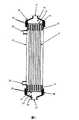
図1は、U字型に束ねた中空糸膜2を、膜モジュールの外筒1内に挿入し、外筒の上端部で中空糸膜束をポッティング材3で接着・固定し、中空糸膜の開口部端面4に接して、フィルター部材5を組み入れて膜ろ過水の集水用のモジュールキャップ8を取り付けた構造をした中空糸膜型ろ過膜モジュールの例を示している。図1に示した中空糸膜型ろ過膜モジュールの使用方法の一例は、次の通りである。すなわち、濁質分を含む原水は、原水供給ノズル10Bから膜モジュール内に導入され、中空糸膜の外側から内側に膜を透過してろ過される。ろ過された膜ろ過水は中空糸膜の中空部内を流れて開口部端面4から集水部7を通って膜モジュールの膜ろ過水出口ノズル6から取り出される。原水中の濁質は中空糸膜の外表面上に捕捉され堆積する。
中空糸膜の外表面上に堆積した濁質のケーク層が厚くなってろ過抵抗が増大し、ろ過に要する差圧が所定の値に達したならば、原水の供給を停止して、必要に応じて、一定量のろ過水をノズル6から逆流させて逆圧洗浄し、さらにノズル11から空気を導入して空気の泡と泡の上昇に伴なって発生する水の上昇流で中空糸膜を揺動させて濁質分からなるケーク層を物理的に除去する。
膜ろ過水は、中空糸膜の開口部から集水部に出た所に置かれた中空糸膜の細孔径より孔径の大きい精密ろ過膜からなるフィルター部材5を通過して膜モジュールの透過水出口ノズル6から、膜モジュールの外部に取り出される。
【0013】
図2は、中空糸膜束12を膜モジュールの外筒21内に挿入し、外筒の両端部で中空糸膜束をポッティング材13および13’で接着・固定し、中空糸膜の開口部端面14および14’に接して、フィルター部材15および15’を組み入れて膜ろ過水の集水用のモジュールキャップ18および18’を取り付けた構造をした中空糸膜型ろ過膜モジュールの例を示している。図2に示した中空糸膜型ろ過膜モジュールの使用方法の一例は、次の通りである。すなわち、濁質分を含む原水は、原水供給ノズル20および/または20’から膜モジュール内に導入され、中空糸膜の外側から内側に膜を透過してろ過される。ろ過された膜透過水は中空糸膜の中空部内を流れて開口部端面14および/または14’から集水部16および/または16’を通って膜モジュールの透過水出口ノズル17および/または17’から取り出される。原水の供給は、中空糸膜型ろ過膜モジュールの下方に位置する中空糸膜束を接着・固定したポッティング部に複数の通路をポッティング部に貫通させて設けて、この原水通路から中空糸膜束内に可及的に均一化して供給する構造としてもよい。原水中の濁質は中空糸膜の外表面上に捕捉され堆積する。
中空糸膜の外表面上に堆積した濁質のケーク層が厚くなってろ過抵抗が増大し、ろ過に要する差圧が所定の値に達したらば、原水の供給を停止して、必要に応じて、一定量のろ過水をノズル17および/または17’から逆流させて逆圧洗浄し、さらにノズル20’から空気を導入して空気の泡と泡の上昇流で中空糸膜を揺動させて濁質分からなるケーク層を物理的に除去する。ポッティング部に貫通させて設けた複数の原水供給通路がある構造の中空糸膜型ろ過膜モジュールの場合には、この原水供給通路から加圧した空気を出して泡および泡の上昇に伴なって発生する水の上昇流で中空糸膜を揺動させて濁質分からなるケーク層を物理的に除去する。
膜ろ過水は、中空糸膜の開口部から集水部に出た所に置かれた中空糸膜の細孔径より孔径の大きい精密ろ過膜からなるフィルター部材15および/または15’を通過して膜モジュールの透過水出口ノズル17および/または17’から、膜モジュールの外部に取り出される。
図3は図2と同様の構成の膜モジュールであるが、膜モジュールの一端部の中空糸膜の全てが封止された閉塞端部からなる例を示している。32は閉塞端部を示し、33は物理洗浄の空気を放散する小孔を複数設けた中心パイプを示している。34は物理洗浄空気の導入孔である。
【0014】
フィルター部材を構成するろ過材料には、精密ろ過膜が使用される。フィルター部材の構成は、図4に示す構成のもの、あるいは図5、またさらに、図6に示すリーフディスクフィルターを複数組み合わせたフィルター部材等のいずれでもよい。
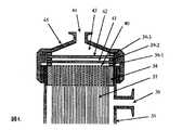
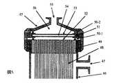
図4は、中空糸膜束37の開口部端面40にパッキン39−1を置いてろ過材料41と密接させ、該ろ過材料とろ過圧による該ろ過材料の変形を防止する押さえ部材42とパッキン39−2で密接させ、膜モジュールの集水用キャップを押さえ部材42とパッキン39−3を介して密接させた構造をしている。図5に示す構成は、フィルター部材がろ過材料54と押さえ部材53とが一体に成形加工された構造のフィルター部材を組み込んだ例を示している。51はろ過材料54と押さえ部材53とを一体に固着しているフランジであり、ろ過材料54と押さえ部材53とを液密に密接させ、中空糸膜束48の開口部端面52の外縁部および膜モジュールキャップ57とフィルター部材とを液密に密接させている。ろ過材料41または54がプリーツ型に加工されていてもよく、液密にシールされていれば有効膜面積を大きくとれるのでむしろ好ましい。
図6はろ過材料がリーフディスクフィルター状に加工されているフィルター部材を中心パイプに複数枚固定したフィルター部材を示している。64がリーフディスクフィルターを示し、65はリーフディスクフィルター間のスペーサーであり、66はフィルター部材と膜モジュールキャップとを液密に固定するO-リングである。フィルターろ過水は中心の集水パイプ67から取り出される。
【0015】
フィルター部材を構成する精密ろ過膜は、中空糸膜の細孔径より孔径の大きい精密ろ過膜であり、高分子材料、金属製膜材料、セラミックス膜材料、ガラス膜材料など、ろ過材料として所定のろ過精度と透過速度および耐久性を持つものであれば、いずれの素材の精密ろ過膜でも使用することができる。
【0016】
精密ろ過膜を構成する高分子材料としては、ポリエチレン、エチレン-テトラフルオロエチレン共重合体、ポリクロロトリフルオロエチレン、ポリテトラフルオロエチレン、ポリビニルフルオライド、テトラフルオロエチレン-ヘキサフルオロプロピレン共重合体、テトラフルオロエチレン-パーフルオロアルキルビニルエーテル共重合体、およびクロロトリフルオロエチレン-エチレン共重合体、ポリフッ化ビニリデン、ポリスルホンおよびポリエーテルスルホン等が使用できる。さらに、これらの高分子の焼結体からなるろ材も使用することができる。
【0017】
金属製の精密ろ過膜としては焼結金属製精密ろ過膜が好ましく使用できる。例えば、SUS304またはSUS316等の微粒子を焼結した焼結金属繊維製精密ろ過膜が特に好ましく使用できる。
【0018】
セラミックスおよびガラス製ろ過材料としては、それらの焼結多孔質体が使用できる。
【0019】
このようなろ過材料の孔径としては0.03μm以上4.0μm以下、好ましくは0.05μm以上2.0μm以下、さらに好ましくは0.1μm以上1.0μm以下の範囲の孔径を有するろ過材料が使用される。孔径を決める条件の一つは、万一中空糸膜が破断した時に混入する濁質分または微生物等のなかで塩素殺菌等で消毒ないし殺滅できない特定のものを除去して、膜モジュールの信頼性を確実にすることができることである。他はフィルター部材の装着によって膜モジュールによるろ過差圧が長期にわたって著しく増加せずに使用できることである。すなわち、ろ過材料の透水性能が1000L/(m2・h)/(100kPa)以上、好ましくは10000L/(m2・h)/(100kPa)以上であるろ過材料からなるフィルター部材が使用される。透水性能の上限は高いほどフィルター部材による圧力損失が小さくて済むが、実際にはろ過材料のろ過精度とトレードオフの関係にあり、ろ過精度を小さくとれば透水性能も小さくなるので、およそ100000L/(m2・h)/(100kPa)以下、より好ましいろ過精度に対しては約10000L/(m2・h)/(100kPa)程度となる。以上のような観点からろ過材料とろ過精度とを検討した結果、上記の孔径範囲が好ましく使用できる。
【0020】
【実施例】
以下、本発明の構成、効果を実施例を用いてさらに詳細に説明する。
【0021】
本発明の効果の確認は次の方法で行なった。クリプトスポリジウムを使った実験は非常に困難なので、通常、所定の粒子の除去性で評価すればよいと言われている。通常、人への感染で問題になるクリプトスポリジウムには2種類あって、楕円体状をしている。小型のもので、(4.5〜5.4)〜(4.2〜5.0)μm、大型の種類で(6.6〜7.9)〜(5.3〜6.5)μmと報告されており、4〜6μmのポリスチレンビーズの除去性で評価することができるとされている。しかし、10−6〜10−7の除去率を実用規模の膜モジュールについてポリスチレンビーズで評価するのも、極めて大量の試験水を必要とするので、実際的ではないため、ここでは原水中に存在する微粒子を計測して評価した。また、従来の凝集沈殿砂ろ過法に対しては、濁度0.1以下に管理することがクリプトスポリジウムに対する暫定指針とされているので、参考に濁度の比較も行なった。
【0022】
実施例1及び比較例1
外径680μm、内径400μm、平均細孔径0.01μmのポリアクリロニトリル多孔質中空糸膜3500本からなる中空糸膜束をU字状に束ね、その両端部を外径110mm、内径104mmの硬質塩化ビニルパイプのハウジング内に挿入して、片端部を接着剤で固定した後、その接着固定部の一部を切断して中空糸膜の内部を開口させた。そして、図5に示すような構造に、SUS304焼結ステンレス鋼繊維からなるろ過精度1.0μmのプリーツ加工をしたろ過材料と押さえ部材と一体に成形された構造のディスクフィルター部材を使用して、中空糸膜型ろ過膜モジュールを製作した。
【0023】
この中空糸型ろ過膜モジュールの中空糸膜をポッティング部近傍で300本切断して本発明の試験用膜モジュールとした(実施例1)。他の1本は、フィルター部材を装着せずに同様に中空糸膜を300本切断して比較対象試験用とした(比較例1)。
【0024】
これらの中空糸膜モジュールを使用して、濁度6.9、直径4μm以上の粒子を8.2×10⁸個/ml含有する原水を8.3l/分の流量で全量ろ過させて、透過水中の濁度と微粒子を測定した。その結果、フィルター部材を装着せずに中空糸膜を300本切断した膜モジュールでは、透過水の濁度が1.4で直径4μm以上の粒子が1.6×108個/ml検出された(比較例1)。これに対して焼結ステンレス鋼繊維製フィルター部材を装着した膜モジュールでは、濁度が0.02で、直径4μm以上の粒子は10個/ml以下で、中空糸膜を切断していない膜モジュールと同等の値を示し、中空糸切断部から漏れ込んだ粒子はフィルター部材で実質的に除去されていた(実施例1)。
【0025】
なお、膜モジュールのろ過差圧はフィルター部材を装着した膜モジュールが50kPaで、フィルター部材を装着していない膜モジュールは25kPaで、差圧の上昇率には差異はなく、問題無く運転することができた。
【0026】
実施例2及び比較例2
外径680μm、内径400μm、平均細孔径0.01μmのポリアクリロニトリル多孔質中空糸膜7400本からなる長さ約1000mmの中空糸膜束を塩ビ製の外筒に挿入してその両端部を接着固定し、端部を切断して中空糸膜の内部を両端部で開口させた形状の図2に示したような中空糸型ろ過膜モジュールを製作した。1本の膜モジュールはノズル20の近傍で中空糸膜を10本切断し、膜モジュールの両開口部端面には、ろ過精度0.6μmの焼結ステンレス鋼繊維をプリーツ加工したディスクフィルター部材を装着した(実施例2)。他の膜モジュールではノズル20の近傍で中空糸膜を10本切断し、焼結ステンレス鋼繊維からなるフィルター部材を装着しなかった(比較例2)。
【0027】
実施例1と同様に、濁度5.2、4μm以上の粒子6.2×10⁸個/mlを含む原水を使用して上記両膜モジュールの透過水の濁度および粒子数を比較した。その結果、フィルター部材を装着しなかった膜モジュールでは、透過水の濁度が0.035、直径4μm以上の粒子が4.0×106個/ml検出された(比較例2)。これに対して焼結ステンレス鋼繊維からなるフィルター部材を装着した膜モジュールでは濁度は0.01以下で、4μm以上の粒子数は10個/ml以下で、中空糸膜を切断していない膜モジュールと差のない結果であった。両者のろ過差圧の差は27kPa以下で、差圧の上昇率には差異はなく、運転上の問題は認められなかった(実施例2)。
【0028】
実施例3及び比較例3
実施例1と同様に、ポリアクリロニトリル多孔質中空糸膜3500本からなる中空糸膜束をU字状に束ね、硬質塩化ビニルパイプのハウジング内に挿入して、片端部を接着剤で固定し、その接着固定部の一部を切断して中空糸膜の内部を開口させた形状の膜モジュールを製作した。膜モジュールの1本は、中空糸膜のポッティング部近傍で約10本切断して、図6に示したような焼結ステンレス鋼繊維の3枚のリーフディスクフィルターからなるフィルター部材を装着した(実施例3)。フィルターのろ過精度は0.3μmであった。他の膜モジュールは中空糸膜10本を切断して、フィルター部材を装着せずに作製した(比較例3)。
【0029】
実施例2と同様に濁度5.2の原水を使って4.2ml/分で供給し全量ろ過して、透過水の濁度と粒子数を測定した。フィルター部材を装着していない膜モジュールの透過水の濁度が0.035、直径4μm以上の粒子が4.0×106個/ml検出された(比較例3)。これに対してフィルター部材を装着した膜モジュールでは濁度は0.01以下で、4μm以上の粒子数は数個/ml以下で、中空糸膜を切断していない膜モジュールと差のない結果であった(実施例3)。なお、両者のろ過差圧は60kPaで、差圧の上昇率には差異はなく、問題なく運転することができた。
【0030】
【発明の効果】
上述したように本発明によれば、水道浄水処理プロセス等の分野で使用する中空糸膜型ろ過膜モジュールにおいて、万一中空糸膜が破断しても、クリプトスポリジウムのような塩素殺菌に対して耐性のある病原性原虫類をはじめとする異物を確実に除去することができる。
【図面の簡単な説明】
【図1】中空糸型ろ過膜モジュールの1例の全体構造の断面図
【図2】中空糸型ろ過膜モジュールの1例の全体構造の断面図
【図3】中空糸型ろ過膜モジュールの1例の全体構造の断面図
【図4】中空糸型ろ過膜モジュールのフィルター部材装着部の断面図
【図5】中空糸型ろ過膜モジュールのフィルター部材装着部の断面図
【図6】中空糸型ろ過膜モジュールのフィルター部材装着部の断面図
【符号の説明】
1:中空糸型ろ過膜モジュール外筒
2:中空糸膜
3:接着固定部(ポッティング部)
4:中空糸膜ポッティング部中空糸膜開口端面
5:フィルター部材
6:膜ろ過水取り出し口
7:膜ろ過水集水部
8:膜ろ過水集水用モジュールキャップ
9:パッキン
10A:物理洗浄空気放出ノズル
10B:原水供給ノズル
11:物理洗浄空気導入口
12:中空糸膜
13:接着固定部(ポッティング部)
14:中空糸膜ポッティング部中空糸膜開口端面
15:フィルター部材
16:膜ろ過水集水部
17:膜ろ過水取り出し口
18:膜ろ過水集水用モジュールキャップ
19:パッキン
20:ノズル
21:中空糸型ろ過膜モジュール外筒
22:中空糸膜
23:接着固定部(ポッティング部)
24:中空糸膜ポッティング部中空糸膜開口端面
25:フィルター部材
26:膜ろ過水集水部
27:膜ろ過水取り出し口
28:膜ろ過水集水用モジュールキャップ
29:パッキン
30および30’:ノズル
31:中空糸型ろ過膜モジュール外筒
32:閉塞端部
33:物理洗浄用エアー吹出し孔付き中心パイプ
34:物理洗浄用エアー導入孔
35:中空糸型ろ過膜モジュール外筒
36ノズル
37:中空糸膜
38:接着固定部(ポッティング部)
39−1:パッキン
39−2:パッキン
39−3:パッキン
40:中空糸膜ポッティング部中空糸膜開口端面
41:ろ過材料
42:押さえ部材
43:膜ろ過水集水部
44:膜ろ過水取り出し口
45:膜ろ過水集水用モジュールキャップ
46:中空糸型ろ過膜モジュール外筒
47:ノズル
48:中空糸膜
49:接着固定部(ポッティング部)
50−1:パッキン
50−2:パッキン
51:フランジ
52:中空糸膜ポッティング部中空糸膜開口端面
53:押さえ部材
54:ろ過材料
55:膜ろ過水取り出し口
56:膜ろ過水集水部
57:膜ろ過水集水用モジュールキャップ
58:中空糸型ろ過膜モジュール外筒
59:ノズル
60:中空糸膜
61:接着固定部(ポッティング部)
62:O―リング
63:中空糸膜ポッティング部中空糸膜開口端面
64:リーフディスクフィルター
65:リーフディスクフィルター用スペーサー
66:O―リング
67:リーフディスクフィルター固定・集水用中心パイプ
68:膜ろ過水集水用モジュールキャップ[0001]
BACKGROUND OF THE INVENTION
The present invention relates to a hollow fiber membrane module forwater purification . More particularly, it relates to a hollow fiber membrane module to be used for water treatment of industrial water or tap water, and in particular to Soraitomaku modulein use in water treatmentfor tapwater.
[0002]
[Prior art]
The membrane separation method is a technology that is widely used while expanding its application field because it has features such as energy saving, space saving, labor saving, and product quality improvement. Examples of membrane separation methods include reverse osmosis, ultrafiltration, microfiltration, gas separation, blood purification, and pervaporation. Moreover, there are hollow fiber membranes, flat membranes, tubular membranes, and the like in the form of separation membranes, which are properly used according to the properties and characteristics of each of the above separation objects.
[0003]
Conventionally, in the field of microfiltration, small disk filters and flat membrane pleated cartridge filters have been used for the purpose of separating and filtering relatively clear aqueous solutions with a relatively small volume of processing. In the field of ultrafiltration, flat membrane filtration devices and hollow fiber membrane modules have been used for the production of ultrapure water, food production, soft drinks, and the like.
[0004]
In recent years, research has been conducted to apply such microfiltration and ultrafiltration hollow fiber membranes to water purification processes that produce industrial water and tap water from river water and groundwater. Microfiltration and ultrafiltration technologies are beginning to be applied to such fields where raw water is used for a long time.
[0005]
A hollow fiber membrane module using a porous hollow fiber membrane can take a very large filtration area per unit volume, has a simple sealing mechanism that separates the undiluted solution to be membrane-treated from the membrane permeate, and has a high water quality. It has various advantages such as superiority and easy operation management.
[0006]
In particular, in the field of water purification process, attention has been focused on the fact that the water quality is superior to the conventional coagulation sedimentation / sand filtration method, and it is easy to automate and save labor, and is being actively introduced. Furthermore, even for tap water contaminated with pathogenic protozoa with strong resistance to chlorine sterilization such as Cryptosporidium, it has been attracting attention as a technology that can reliably remove pathogenic protozoa, and a treatment method for such raw water Recommended as.
[0007]
However, when used for such a purpose, the hollow fiber membrane module has a possibility that the hollow fiber membrane isbroken and rawwater is mixed into the membrane filtrate. For normal water quality evaluation items, such as turbidity, even if some hollow fiber membranes break, there is almost no risk of problems, but in the case of Cryptosporidium, it is extremely strong because of its strong infectivity. Even if a small number of hollow fiber membranes break, it may cause a problem.
[0008]
[Problems to be solved by the invention]
The object of the present invention is to solve the drawbacks of the conventional hollow fiber membrane type module, and even if the hollow fiber membrane breaks, microorganisms such as pathogenic protozoa represented by Cryptosporidium do not leak. An object of the present invention is to provide a hollow fiber membrane filtration membrane module and a method for producing water for industrial use or tap water.
[0009]
[Means for Solving the Problems]
In order to achieve the above object, the present invention comprises the following configurations.
That is, in theexternal pressure type hollow fiber membrane type filtration membrane module, a filter member made of aprecision filtration membrane having a pore diameter larger than the pore diameter of the hollow fiber membrane isattached to thehollow fiber membrane opening end surface of the hollow fiber membranepotting portion for taking out membrane filtrate water.The hollow fiber membrane filtrateis configured to be filtered by the filter member, andhas the following preferred embodiment.
(1)Precision filtration consisting membrane filter memberOrganization for close contact with the potting portion hollow fiber membranes open end face and a precision filtration membrane in a liquid tightmanner, the pressing member to prevent deformation of the microfiltration membrane and the microfiltration membrane,and, the filter member and the membrane filtrate water collecting module cap and liquid-tight in close contact toOrganization or Ranaru a.
(2 ) The filter member ismade of a polymermicrofiltration membrane .
(3) filtermember, RaNarukoandorsinteredmetal microfiltrationmembranes.
[0010]
Inthe presentinvention, the water purification process for the preparation of industrial water or tap water, thesupplied raw water to one of the hollow fiber membrane typemodules,passes through the hollow fiber membranewas further transmitted throughthefull Iruta member The present invention provides awater purification method characterized by taking out water.
[0011]
DETAILED DESCRIPTION OF THE INVENTION
1 to 3 show an example of the hollow fiber membrane module of the present invention. Figure 4-6 is a diagram of the potting portion of a cross section of the hollow fiber membrane filtration membrane module schematically showing the present invention fitted with a filter member made of amicrofiltrationmembrane,a hollow fiber membrane potting portion hollow to take out the membrane filtration water A filter member made of amicrofiltration membrane having a pore size larger than the pore size ofthe hollow fiber membrane isattached to theend surface of the yarn membraneopening, and it is configured to filter the hollow fiber membrane filtrate with the filter member. .
[0012]
1, a
Filtration resistance increases cake layer of suspended substances deposited on the outer surface of the hollow fiber membrane becomes thick,Do differential pressure required for filtration reaches a predetermined value mules, by stopping the supply of raw water, required Accordingly, a certain amount of filtered water is caused to flow backward from the nozzle 6 for back pressure washing, and air is introduced from the
The membrane filtrate passes through the filter member 5 made of aprecision filtrationmembrane having a pore diameter larger than the pore diameter of the hollow fiber membrane placed at the water collection portion from the opening of the hollow fiber membrane and passes through the membrane module. It is taken out from the outlet nozzle 6 to the outside of the membrane module.
[0013]
FIG. 2 shows that the hollow
When the turbid cake layer deposited on the outer surface of the hollow fiber membrane becomes thicker and the filtration resistance increases, and the differential pressure required for filtration reaches a predetermined value, the supply of raw water is stopped, and if necessary Then, a certain amount of filtered water is reversely flown from the
Membrane filtration water passes through the
FIG. 3 shows a membrane module having the same configuration as that of FIG. 2, but shows an example of a closed end portion in which all of the hollow fiber membranes at one end portion of the membrane module are sealed.
[0014]
The filtering material constituting the filtermember, precision filtrationmembraneRu isused. Construction offull Iruta member is of a configuration shown in FIG. 4, or 5, or even may be either a filter member such as a combination of a plurality of leaf disc filter shown in FIG.
FIG. 4 shows a pressing
FIG. 6 shows a filter member in which a plurality of filter members in which a filtering material is processed into a leaf disk filter shape are fixed to a central pipe.
[0015]
Microfiltration membrane constituting the filter memberis a great microfiltration membrane having a pore size than the pore size of the hollow fiber membranes, polymeric materials, metallic film material, a ceramic membrane material, such as glass film material, a predetermined filtering as filtering material as long as it has the accuracy and transmission speed and durability, it can be used evenmicrofiltrationmembrane of any material.
[0016]
The polymer materialsconstituting the microfiltration membrane include polyethylene, ethylene-tetrafluoroethylene copolymer, polychlorotrifluoroethylene, polytetrafluoroethylene, polyvinyl fluoride, tetrafluoroethylene-hexafluoropropylene copolymer, tetra Fluoroethylene-perfluoroalkyl vinyl ether copolymer, chlorotrifluoroethylene-ethylene copolymer, polyvinylidene fluoride, polysulfone, polyethersulfone and thelike can be used. Furthermore, itis also possible touse filter media made of a sintered product of these polymers.
[0017]
Sintered metal microfiltration membranes witha metalmicrofiltration membranesgood Mashiku be used.For example,a sintered metal fiber-made microfiltrationmembrane sintered fine particles, such as SUS304 or SUS316 are particularly preferably used.
[0018]
As ceramic and glass filter materials, those sintered porous bodies can be used.
[0019]
As the pore size of such a filtration material, a filtration material having a pore size in the range of 0.03 μm to 4.0 μm, preferably 0.05 μm to 2.0 μm, more preferably 0.1 μm to 1.0 μm is used. Is done. One of the conditions for determining the pore size is to remove the turbid matter mixed in when the hollow fiber membrane breaks or the specific microorganisms that cannot be disinfected or disinfected by chlorination etc. It is possible to ensure sex. The other is that the filtration differential pressure due to the membrane module can be used without significantly increasing over a long period by mounting the filter member. That is, a filter member made of a filtration material having a water permeability of 1000 L / (m2 · h) / (100 kPa) or more, preferably 10,000 L / (m2 · h) / (100 kPa) or more is used. The higher the upper limit of the water permeability, the smaller the pressure loss due to the filter member, but in reality there is a trade-off relationship with the filtration accuracy of the filtration material. (M2 · h) / (100 kPa) or less, about 10000 L / (m2 · h) / (100 kPa) for more preferable filtration accuracy. As a result of examining the filtration material and filtration accuracy from the above viewpoint, the above pore diameter range can be preferably used.
[0020]
【Example】
Hereinafter, the configuration and effects of the present invention will be described in more detail with reference to examples.
[0021]
The effect of the present invention was confirmed by the following method. Since experiments using Cryptosporidium are very difficult, it is usually said that the evaluation should be based on the removability of predetermined particles. There are two types of Cryptosporidium, which usually cause problems with human infection, and have an ellipsoidal shape. Small (4.5-5.4)-(4.2-5.0) μm, and large types (6.6-7.9)-(5.3-6.5) μm are reported, with 4-6 μm removal of polystyrene beads. It can be evaluated. However, it is impractical to evaluate the removal rate of 10−6 to 10−7 with a polystyrene bead for a practical scale membrane module because it requires a very large amount of test water. The fine particles to be measured were measured and evaluated. In addition, for the conventional agglomerated sedimentation sand filtration method, the turbidity is controlled by reference to Cryptosporidium because the turbidity is controlled to 0.1 or less.
[0022]
Example 1and Comparative Example 1
A bundle of hollow fiber membranes composed of 3,500 polyacrylonitrile porous hollow fiber membranes having an outer diameter of 680 μm, an inner diameter of 400 μm, and an average pore diameter of 0.01 μm is bundled in a U shape, and both ends thereof are hard vinyl chloride having an outer diameter of 110 mm and an inner diameter of 104 mm. After inserting into the pipe housing and fixing one end portion with an adhesive, a part of the adhesive fixing portion was cut to open the inside of the hollow fiber membrane. And, in the structure as shown in FIG. 5, using a filter material made of SUS304 sintered stainless steel fiber and pleated with a filtration accuracy of 1.0 μm and a disk filter member formed integrally with a pressing member, A hollow fiber membrane filtration membrane module was manufactured.
[0023]
The hollow fiber filtration membrane modules hollow fibermembrane Le cut 300 present in the potting portion near to the test membrane module of the present invention(Example 1). For the other one, 300 hollow fiber membranes weresimilarly cut without attaching a filter member and used for a comparative test(Comparative Example 1) .
[0024]
Using these hollow fiber membrane modules, raw water containing 8.2 ×10⁸ particles / ml of turbidity of 6.9 and diameter of 4 μm or more was filtered at a flow rate of 8.3 l / min. Turbidity and fine particles in water were measured. As a result, in the membrane module in which 300 hollow fiber membranes were cut without attaching the filter member, particles having a turbidity of permeated water of 1.4 and a diameter of 4 μm or more were detected at 1.6 ×10⁸ particles / ml.(Comparative Example 1) On the other hand, in a membrane module equipped with a sintered stainless steel fiber filter member, the membrane module has a turbidity of 0.02 and particles having a diameter of 4 μm or more are 10 particles / ml or less, and the hollow fiber membrane is not cut. The particle which leaked from the hollow fiber cutting part was substantially removed with the filter member(Example 1) .
[0025]
The filtration differential pressure of the membrane module is 50 kPa for the membrane module equipped with the filter member, and 25 kPa for the membrane module not equipped with the filter member. did it.
[0026]
Example 2and Comparative Example 2
A hollow fiber membrane bundle of about 1000 mm in length composed of 7400 polyacrylonitrile porous hollow fiber membranes having an outer diameter of 680 μm, an inner diameter of 400 μm, and an average pore diameter of 0.01 μm is inserted into an outer tube made of polyvinyl chloride, and both ends thereof are bonded and fixed. Then, a hollow fiber type filtration membrane module as shown in FIG. 2 having a shape in which the end portion was cut and the inside of the hollow fiber membrane was opened at both end portions was manufactured. One membrane module cuts 10 hollow fiber membranes in the vicinity of the
[0027]
In the same manner as in Example 1, the turbidity and the number of particles of the permeated water of the above two membrane modules were compared using raw water containing 6.2 ×10⁸ particles / ml having a turbidity of 5.2, 4 μm or more. As a result, in the membrane module not equipped with the filter member, the turbidity of the permeated water was 0.035, and particles having a diameter of 4 μm or more were detected at 4.0 ×10⁶ particles / ml(Comparative Example 2) . In contrast, in a membrane module equipped with a filter member made of sintered stainless steel fiber, the turbidity is 0.01 or less, the number of particles of 4 μm or more is 10 particles / ml or less, and the membrane does not cut the hollow fiber membrane. The result was no different from the module. The difference in filtration differential pressure between them was 27 kPa or less, and there was no difference in the rate of increase in differential pressure, and no operational problems were observed(Example 2) .
[0028]
Example 3 and Comparative Example 3
In the same manner as in Example 1, a hollow fiber membrane bundle composed of 3500 polyacrylonitrile porous hollow fiber membranes was bundled in a U shape, inserted into a housing of a hard vinyl chloride pipe, and one end portion was fixed with an adhesive, A membrane module having a shape in which a part of the adhesive fixing portion was cut to open the hollow fiber membrane was manufactured. One membrane module was cut about 10 near the potting portion of the hollow fiber membrane, and a filter member composed of three leaf disk filters of sintered stainless steel fibers as shown in FIG. 6 was mounted(implementation). Example 3) . The filtration accuracy of the filter was 0.3 μm. Other membrane modules were prepared by cutting 10 hollow fiber membranes and not attaching a filter member(Comparative Example 3 ).
[0029]
In the same manner as in Example 2, the raw water having a turbidity of 5.2 was supplied at 4.2 ml / min and the whole amount was filtered, and the turbidity and the number of particles of the permeated water were measured. The turbidity of the permeated water of the membrane module not equipped with a filter member was 0.035, and particles having a diameter of 4 μm or more were detected at 4.0 ×10⁶ particles / ml(Comparative Example 3) . On the other hand, the membrane module equipped with the filter member has a turbidity of 0.01 or less, and the number of particles of 4 μm or more is several particles / ml or less, which is not different from the membrane module that does not cut the hollow fiber membrane.(Example 3) . In addition, both filtration differential pressure | voltages were 60 kPa, there was no difference in the increase rate of differential pressure | voltage, and it was able to drive | operate without a problem.
[0030]
【The invention's effect】
According to the present invention as described above, in the hollow fiber membrane filtration membrane module used in the fields such as water water treatment processes, even broken by any chance hollow fiber membrane, to chlorination, such asCryptosporidium Porijiumu resistant Te contaminants, including pathogenicoriginal insects can be reliably removed.
[Brief description of the drawings]
FIG. 1 is a cross-sectional view of the entire structure of an example of a hollow fiber type filtration membrane module. FIG. 2 is a cross-sectional view of the entire structure of an example of a hollow fiber type filtration membrane module. Cross-sectional view of the overall structure of the example [Fig. 4] Cross-sectional view of the filter member mounting portion of the hollow fiber type filtration membrane module [Fig. 5] Cross-sectional view of the filter member mounting portion of the hollow fiber type filtration membrane module [Fig. Cross-sectional view of the filter member mounting part of the filtration membrane module [Explanation of symbols]
1: Hollow fiber filtration membrane module outer cylinder 2: Hollow fiber membrane 3: Adhesive fixing part (potting part)
4: Hollow fiber membrane potting part Hollow fiber membrane opening end face 5: Filter member 6: Membrane filtrate outlet 7: Membrane filtrate collection part 8: Membrane filtrate collection module cap 9:
14: Hollow fiber membrane potting part Hollow fiber membrane opening end face 15: Filter member 16: Membrane filtrate collecting part 17: Membrane filtrate outlet 18: Membrane filtrate collection module cap 19: Packing 20: Nozzle 21: Hollow Thread-type filtration membrane module outer cylinder 22: hollow fiber membrane 23: adhesive fixing part (potting part)
24: Hollow fiber membrane potting part Hollow fiber membrane opening end face 25: Filter member 26: Membrane filtrate collection part 27: Membrane filtrate collection port 28: Membrane filtrate collection module cap 29:
39-1: Packing 39-2: Packing 39-3: Packing 40: Hollow fiber membrane potting part Hollow fiber membrane opening end face 41: Filtration material 42: Holding member 43: Membrane filtrate collecting part 44: Membrane filtrate extraction port 45: Module cap for membrane filtration water collection 46: Hollow fiber filtration membrane module outer cylinder 47: Nozzle 48: Hollow fiber membrane 49: Adhesive fixing part (potting part)
50-1: Packing 50-2: Packing 51: Flange 52: Hollow fiber membrane potting part Hollow fiber membrane opening end face 53: Holding member 54: Filtration material 55: Membrane filtrate outlet 56: Membrane filtrate collection part 57: Membrane filtration water collection module cap 58: hollow fiber type filtration membrane module outer cylinder 59: nozzle 60: hollow fiber membrane 61: adhesive fixing part (potting part)
62: O-ring 63: Hollow fiber membrane potting part hollow fiber membrane opening end face 64: Leaf disk filter 65: Leaf disk filter spacer 66: O-ring 67: Leaf disk filter fixing / water collecting center pipe 68: Membrane filtration Water cap module cap
Claims (5)
Translated fromJapanesePriority Applications (1)
| Application Number | Priority Date | Filing Date | Title |
|---|---|---|---|
| JP16706598AJP3924926B2 (en) | 1998-06-15 | 1998-06-15 | Hollow fiber membrane filtration membrane module |
Applications Claiming Priority (1)
| Application Number | Priority Date | Filing Date | Title |
|---|---|---|---|
| JP16706598AJP3924926B2 (en) | 1998-06-15 | 1998-06-15 | Hollow fiber membrane filtration membrane module |
Publications (3)
| Publication Number | Publication Date |
|---|---|
| JP2000000439A JP2000000439A (en) | 2000-01-07 |
| JP2000000439A5 JP2000000439A5 (en) | 2004-08-19 |
| JP3924926B2true JP3924926B2 (en) | 2007-06-06 |
Family
ID=15842762
Family Applications (1)
| Application Number | Title | Priority Date | Filing Date |
|---|---|---|---|
| JP16706598AExpired - Fee RelatedJP3924926B2 (en) | 1998-06-15 | 1998-06-15 | Hollow fiber membrane filtration membrane module |
Country Status (1)
| Country | Link |
|---|---|
| JP (1) | JP3924926B2 (en) |
Families Citing this family (36)
| Publication number | Priority date | Publication date | Assignee | Title |
|---|---|---|---|---|
| ES2353254T3 (en) | 1996-12-20 | 2011-02-28 | Siemens Water Technologies Corp. | WASHING PROCEDURE |
| AUPR421501A0 (en) | 2001-04-04 | 2001-05-03 | U.S. Filter Wastewater Group, Inc. | Potting method |
| AUPR692401A0 (en) | 2001-08-09 | 2001-08-30 | U.S. Filter Wastewater Group, Inc. | Method of cleaning membrane modules |
| US7247238B2 (en) | 2002-02-12 | 2007-07-24 | Siemens Water Technologies Corp. | Poly(ethylene chlorotrifluoroethylene) membranes |
| AUPS300602A0 (en) | 2002-06-18 | 2002-07-11 | U.S. Filter Wastewater Group, Inc. | Methods of minimising the effect of integrity loss in hollow fibre membrane modules |
| KR101002466B1 (en) | 2002-10-10 | 2010-12-17 | 지멘스 워터 테크놀로지스 코포레이션 | Back wash method |
| CN101058446A (en)* | 2003-07-08 | 2007-10-24 | 三菱丽阳株式会社 | Method of cleaning water purifier |
| NZ545206A (en) | 2003-08-29 | 2009-03-31 | Siemens Water Tech Corp | Backwash |
| CA2544626C (en) | 2003-11-14 | 2016-01-26 | U.S. Filter Wastewater Group, Inc. | Closed aeration and backwash device for use with membrane filtration module |
| US8758621B2 (en) | 2004-03-26 | 2014-06-24 | Evoqua Water Technologies Llc | Process and apparatus for purifying impure water using microfiltration or ultrafiltration in combination with reverse osmosis |
| CN101043933B (en) | 2004-09-07 | 2012-09-05 | 西门子工业公司 | Reduction of backwash liquid waste |
| AU2005284677B2 (en) | 2004-09-14 | 2010-12-23 | Evoqua Water Technologies Llc | Methods and apparatus for removing solids from a membrane module |
| NZ553771A (en) | 2004-09-15 | 2010-11-26 | Siemens Water Tech Corp | Continuously variable aeration of membrane filtration system and flow control device when used in such application |
| WO2006066350A1 (en) | 2004-12-24 | 2006-06-29 | Siemens Water Technologies Corp. | Simple gas scouring method and apparatus |
| WO2006066319A1 (en) | 2004-12-24 | 2006-06-29 | Siemens Water Technologies Corp. | Cleaning in membrane filtration systems |
| JP2008539054A (en) | 2005-04-29 | 2008-11-13 | シーメンス・ウォーター・テクノロジーズ・コーポレイション | Chemical cleaning for membrane filters |
| US8858796B2 (en) | 2005-08-22 | 2014-10-14 | Evoqua Water Technologies Llc | Assembly for water filtration using a tube manifold to minimise backwash |
| US8293098B2 (en) | 2006-10-24 | 2012-10-23 | Siemens Industry, Inc. | Infiltration/inflow control for membrane bioreactor |
| US8318028B2 (en) | 2007-04-02 | 2012-11-27 | Siemens Industry, Inc. | Infiltration/inflow control for membrane bioreactor |
| US9764288B2 (en) | 2007-04-04 | 2017-09-19 | Evoqua Water Technologies Llc | Membrane module protection |
| CA2688455C (en) | 2007-05-29 | 2019-12-03 | Siemens Water Technologies Corp. | Pulsed random two phase gas/liquid flow for cleaning membrane surfaces |
| WO2010009518A1 (en) | 2008-07-24 | 2010-01-28 | Siemens Water Technologies Corp. | Frame system for membrane filtration modules |
| AU2010101488B4 (en) | 2009-06-11 | 2013-05-02 | Evoqua Water Technologies Llc | Methods for cleaning a porous polymeric membrane and a kit for cleaning a porous polymeric membrane |
| WO2011136888A1 (en) | 2010-04-30 | 2011-11-03 | Siemens Industry, Inc | Fluid flow distribution device |
| WO2012040412A1 (en) | 2010-09-24 | 2012-03-29 | Siemens Industry, Inc. | Fluid control manifold for membrane filtration system |
| WO2013048801A1 (en) | 2011-09-30 | 2013-04-04 | Siemens Industry, Inc. | Improved manifold arrangement |
| KR102177864B1 (en) | 2011-09-30 | 2020-11-13 | 에보쿠아 워터 테크놀로지스 엘엘씨 | Isolation valve |
| WO2014004645A1 (en) | 2012-06-28 | 2014-01-03 | Siemens Industry, Inc. | A potting method |
| DE112013004713T5 (en) | 2012-09-26 | 2015-07-23 | Evoqua Water Technologies Llc | Membrane safety device |
| AU2013231145B2 (en) | 2012-09-26 | 2017-08-17 | Evoqua Water Technologies Llc | Membrane potting methods |
| AU2013323934A1 (en) | 2012-09-27 | 2015-02-26 | Evoqua Water Technologies Llc | Gas scouring apparatus for immersed membranes |
| KR101303993B1 (en) | 2013-06-14 | 2013-09-10 | 한국정수공업 주식회사 | Hollow fiber membrane filter with screen |
| EP3052221B1 (en) | 2013-10-02 | 2022-12-14 | Rohm & Haas Electronic Materials Singapore Pte. Ltd | Device for repairing a membrane filtration module |
| US10322375B2 (en) | 2015-07-14 | 2019-06-18 | Evoqua Water Technologies Llc | Aeration device for filtration system |
| KR102283852B1 (en) | 2016-08-29 | 2021-08-02 | 이엠디 밀리포어 코포레이션 | Fixed rigid wall device for compressed pleat configuration filters |
| CN113694734A (en)* | 2021-09-09 | 2021-11-26 | 河北森斯环保科技有限公司 | Device for extracting gluconic acid by membrane method |
- 1998
- 1998-06-15JPJP16706598Apatent/JP3924926B2/ennot_activeExpired - Fee Related
Also Published As
| Publication number | Publication date |
|---|---|
| JP2000000439A (en) | 2000-01-07 |
Similar Documents
| Publication | Publication Date | Title |
|---|---|---|
| JP3924926B2 (en) | Hollow fiber membrane filtration membrane module | |
| US4547289A (en) | Filtration apparatus using hollow fiber membrane | |
| JPH03504820A (en) | Spiral-wound reverse osmosis membrane cell | |
| JP3253961B2 (en) | Inorganic filtration unit | |
| JP2000157846A (en) | Hollow fiber membrane cartridge | |
| CN101541406A (en) | Flat-membrane element for filtration and flat-membrane filtration module | |
| JPH07275665A (en) | Hollow fiber membrane module | |
| CA2000055A1 (en) | Microfilter device | |
| GB2573352A (en) | Hollow fiber membrane for filtration of liquids | |
| JPH0365222A (en) | Tubular filter element | |
| GB2211757A (en) | Microporous filter and method | |
| JP3131092B2 (en) | Hollow fiber membrane module assembly | |
| JPH0212130B2 (en) | ||
| JP3381990B2 (en) | Hollow fiber membrane module | |
| JPS6397203A (en) | Filtration cartridge | |
| JPH08332483A (en) | Wastewater treatment method | |
| JP2000015062A (en) | Membrane filter | |
| JP2000070683A (en) | Hollow fiber membrane type permeation membrane module | |
| JP2000079329A (en) | Filter membrane module | |
| JPH11137974A (en) | Spiral type membrane element | |
| JP3694536B2 (en) | Membrane module | |
| JP2001321645A (en) | Filter membrane element and method for manufacturing permeated water | |
| US5110476A (en) | Hollow fiber membrane system for removal of viruses and bacteria | |
| JPH0679147A (en) | Filtration method | |
| JPH04190834A (en) | Cross-flow type filter |
Legal Events
| Date | Code | Title | Description |
|---|---|---|---|
| A977 | Report on retrieval | Free format text:JAPANESE INTERMEDIATE CODE: A971007 Effective date:20040928 | |
| A131 | Notification of reasons for refusal | Free format text:JAPANESE INTERMEDIATE CODE: A131 Effective date:20061114 | |
| A521 | Written amendment | Free format text:JAPANESE INTERMEDIATE CODE: A523 Effective date:20070115 | |
| TRDD | Decision of grant or rejection written | ||
| A01 | Written decision to grant a patent or to grant a registration (utility model) | Free format text:JAPANESE INTERMEDIATE CODE: A01 Effective date:20070206 | |
| A61 | First payment of annual fees (during grant procedure) | Free format text:JAPANESE INTERMEDIATE CODE: A61 Effective date:20070219 | |
| LAPS | Cancellation because of no payment of annual fees |