JP3923746B2 - Keyboard switch device - Google Patents
Keyboard switch deviceDownload PDFInfo
- Publication number
- JP3923746B2 JP3923746B2JP2001078454AJP2001078454AJP3923746B2JP 3923746 B2JP3923746 B2JP 3923746B2JP 2001078454 AJP2001078454 AJP 2001078454AJP 2001078454 AJP2001078454 AJP 2001078454AJP 3923746 B2JP3923746 B2JP 3923746B2
- Authority
- JP
- Japan
- Prior art keywords
- rubber cap
- air
- sheet
- switch device
- cap
- Prior art date
- Legal status (The legal status is an assumption and is not a legal conclusion. Google has not performed a legal analysis and makes no representation as to the accuracy of the status listed.)
- Expired - Fee Related
Links
- 125000006850spacer groupChemical group0.000claimsdescription16
- 238000009423ventilationMethods0.000claimsdescription5
- 229920001971elastomerPolymers0.000description55
- 239000000428dustSubstances0.000description10
- 239000010408filmSubstances0.000description10
- 239000012528membraneSubstances0.000description10
- 229910052751metalInorganic materials0.000description8
- 239000002184metalSubstances0.000description8
- 239000000853adhesiveSubstances0.000description3
- 230000001070adhesive effectEffects0.000description3
- 229920000139polyethylene terephthalatePolymers0.000description3
- 239000005020polyethylene terephthalateSubstances0.000description3
- 238000007639printingMethods0.000description3
- 229910052782aluminiumInorganic materials0.000description2
- XAGFODPZIPBFFR-UHFFFAOYSA-NaluminiumChemical compound[Al]XAGFODPZIPBFFR-UHFFFAOYSA-N0.000description2
- 230000007423decreaseEffects0.000description2
- 230000000694effectsEffects0.000description2
- 229920005989resinPolymers0.000description2
- 239000011347resinSubstances0.000description2
- 229920000122acrylonitrile butadiene styrenePolymers0.000description1
- 230000001174ascending effectEffects0.000description1
- 239000000470constituentSubstances0.000description1
- 230000000994depressogenic effectEffects0.000description1
- 238000010586diagramMethods0.000description1
- 239000000463materialSubstances0.000description1
- 230000002093peripheral effectEffects0.000description1
- 229920000728polyesterPolymers0.000description1
- -1polyethylene terephthalatePolymers0.000description1
- 238000007650screen-printingMethods0.000description1
- 229920002379silicone rubberPolymers0.000description1
- 239000004945silicone rubberSubstances0.000description1
- 229920003002synthetic resinPolymers0.000description1
- 239000000057synthetic resinSubstances0.000description1
- 239000010409thin filmSubstances0.000description1
Images


Landscapes
- Input From Keyboards Or The Like (AREA)
- Push-Button Switches (AREA)
Description
Translated fromJapanese【0001】
【発明の属する技術分野】
本発明は、キーボード用スイッチ装置に関し、特にノート型のパーソナルコンピュータやノート型ワードプロセッサなどに搭載される薄型のキーボードに使用して好適なキーボード用スイッチ装置に関する。
【0002】
【従来の技術】
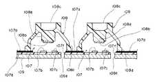
従来のキーボード用スイッチ装置100は、図8に示すように、ラバーキャップ108を有するメンブレンスイッチ107を有している。
このメンブレンスイッチ107は、絶縁性のフィルムシート107a上にスイッチ素子である、互いに対向する第1と第2の電極107b、107cが印刷等により形成されている。
この第1、第2電極107b、107cは、後述するラバーキャップ108の導電部108bが接触することにより、電気的に導通してスイッチON状態になるようになっている。
【0003】
また、第1、第2電極107b、107cの周辺には、第1、第2電極107b、107cを露出させた状態で、所定の厚さのレジスト膜107dが形成され、このレジスト膜107dにより、第1、第2電極107b、107cから引き出された配線パターン(図示せず)の上面が覆われて絶縁されている。
また、第1あるいは第2電極107b、107c近傍のフィルムシート107aには、空気孔107fが打ち抜き形成されている。
【0004】
また、第1、第2電極107b、107c上には、内部がドーム状に形成されたラバーキャップ108が配設されている。このラバーキャップ108は、内部のドーム状の天井部から下方に突出して押圧突起108aが形成され、この押圧突起108aの下端部には、導電性の膜からなる導電部108bが印刷等により形成されている。
また、ラバーキャップ108には、ドーム状の天井部から上方に突出する円形状の頂部108cが形成されている。また、ドーム状の下部にはスカート部108dが形成され、このスカート部108dが、接着剤等でメンブレンスイッチ107のレジスト膜107d上に固着されて、メンブレンスイッチ107とラバーキャップ108とが一体化されている。
【0005】
また、メンブレンスイッチ107の下部には、アルミニウム等の金属板からなる平坦状のメタルプレート109が配設されている。このメタルプレート109には、メンブレンスイッチ107の空気孔107fが位置する部分に、同じ大きさの空気孔109fが打ち抜き形成されており、ラバーキャップ108が押圧されて変形したときに、ラバーキャップ108内部の空気が空気孔107f、109fを通じて外部に逃げて、ラバーキャップ108が変形容易になっている。
ところで、ラバーキャップ108を下方に押し下げると、ラバーキャップ108内部の容積が一旦減少し、その後、ラバーキャップ108の復帰と共に、その容積内に空気孔107f、109fを通じて外部から空気が流入する。
【0006】
【発明が解決しようとする課題】
このようなメンブレンスイッチ107のスイッチング動作が行われると、空気とともにごみや埃などがラバーキャップ108内部に侵入して、第1、第2電極107b、107cおよび導電部108bに付着するおそれがある。
そして、ラバーキャップ108を押し下げて、スイッチング動作(スイッチオン動作)するにも、これらごみや埃により、第1、第2電極107b、107cと導電部108bとの接触が妨げられ、導通しないおそれがある。
【0007】
そこで、これらごみや埃がラバーキャップ108の内部に侵入しにくくするために、空気孔107f、109fの径を小さくすることが考えられるが、キーボードとして配列された多数のラバーキャップ108が同時に複数個押し下げられられると、その作動に要する押圧力を増大させなければならないので、空気孔107f、109fの径を小さくすることができない。
【0008】
近年、ノート型パーソナルコンピュータは、その普及に伴って、益々薄型化が要求されてきている。
したがって、キーボードでは、上記キーボード用スイッチ装置100の下部、すなわちメタルプレート109と図示しない構成ユニットのケース部材の間の隙間が十分に取れなくなってきている。
そして、メタルプレート109とケース部材と密着した場合には、スイッチング動作のため、ラバーキャップ108を押し下げようとしたときに、ラバーキャップ108内部の空気が空気孔107f、109fを通じて外部に逃げることができず、ラバーキャップ108を十分に押し下げることができないことがある。
そのため、ラバーキャップ108への押圧力(操作圧)が変動してしまい、そのメンブレンスイッチ107のクリック感などのフィーリングも悪くなる。
【0009】
本発明の目的は、耐塵性に優れ、ラバーキャップ108への押圧力(操作圧)の変動を少なくして、信頼性のあるキーボード用スイッチ装置を簡単な構成で提供することにある。
【0010】
【課題を解決するための手段】
上記課題の少なくとも1つを解決するための第1の解決手段として、昇降可能な複数のキートップと、該各キートップを上方にそれぞれ弾性付勢する弾性キャップと、前記各弾性キャップが上面に設けられ、前記キートップの昇降動作に伴って変形する前記弾性キャップを介して、スイッチングを行う前記弾性キャップの内部に配置された第1の通気孔を有するシートスイッチと、該シートスイッチを上方に積層したベースプレートと、前記シートスイッチと前記ベースプレート間に積層され、前記第1の通気孔と通ずる空気逃げ部を有するスペーサシートとを備え、前記シートスイッチには、前記弾性キャップの外方で、前記空気逃げ部に通ずる第2の通気孔が形成されたものである。
【0011】
また、第2の解決手段として、空気逃げ部はキートップの配列方向に対応した長孔部である。
【0013】
【発明の実施の形態】
本発明の一実施形態であるキーボード用スイッチ装置を図1乃至図7に基づいて以下に説明する。
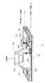
図1乃至図3に示すように、キーボード用スイッチ装置は、アルミニウム等の金属からなる平板状のベースプレート10と、該ベースプレート10上に積層して配設されたスペーサシート20と、このスペーサシート20上に積層して配設された絶縁性シート30と、絶縁性シート30上に取付けられたラバーキャップ(弾性キャップ)40と、ラバーキャップ40を押し下げるキートップ50と、ラバーキャップ40を配置するための矩形状をした複数の開口部60aを有する保持プレート60とから主に構成されている。
【0014】
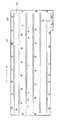
図4に示すように、略長方形状をした上記スペーサシート20は、PET(ポリエチレンテレフタレート)、ポリエステルなどの樹脂フィルムからなり、その長手方向に沿って、幅寸法を同じにした6本の帯状をした空気逃げ部としての長孔部22が互いに平行に打ち抜き形成されている。
また、スペーサシート20には、その周辺部分、さらに長孔部22を除いた中央部分に、位置決め用の複数の位置決め穴24が所定の間隔で形成されている。
なお、この長孔部22は、後述するキートップ50の配列方向と一致している
。
【0015】
上記絶縁性シート30は、シートスイッチとして、図1乃至図3に示すように、PETなどの樹脂フィルムからなる透明な絶縁性のベースシートと、導電性ペーストからなる導電パターン部とをスクリーン印刷にて一体成形した、一種のフレキシブル回路基板(FPC)とを備えている。また、導電パターン部にはレジスト膜が一体形成されている。
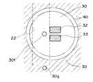
そして、図5に示すように、絶縁性シート30の上面には、導電パターン部に接続する第1、第2固定電極32、33が、一組ずつ所定の間隔に並設して配置されるとともに、レジスト膜から露出して形成されている。さらに、絶縁性シート30には、1組の第1、第2固定電極32,33近傍に1つの小さな穴部(第1の通気孔)30fがそれぞれ形成されている。
また、絶縁性シート30には、ラバーキャップ40の外方で、各長孔部22に通ずる複数の通気孔(第2の通気孔)30gがそれぞれ導電パターン部を避けて貫通形成されている。すなわち、長孔部22を介して穴部30fに通じる通気孔30gが形成されている。
【0016】
上記ラバーキャップ(弾性キャップ)40は、図3、図5および図6に示すように、絶縁性のあるシリコーンゴムなどでドーム状に形成され、ドーム状の天井部分から上方に突出する筒状の頂部40cと、頂部40cの周囲から下向きに延びるスカート部40dと、スカート部40dの下端部分に延設された厚肉の鍔部40fとからなる下向き開放のキャップ状に一体成形されている。
このラバーキャップ40には、ドーム状の内部の天井部(頂部40c)に下方側に向けて一体に突出形成した押圧突起と、この押圧突起の先端(下端部)に印刷形成された導電性の膜を有する可動電極42とを備えている。
【0017】
さらに、ラバーキャップ40は、可動電極42と第1、第2固定電極32,33とが対向するように、接着剤などを塗布した鍔部40fの下面を絶縁性シート30の上面に貼り付け固定している。
そして、ラバーキャップ40の押し下げにより、可動電極42が第1、第2固定電極32,33と接離して、シートスイッチである絶縁性シート30はスイッチング動作をするようになっている。
【0018】
なお、可動電極42は、押圧突起の代わりに、ドーム状の内部の天井部(頂部40c)に下方側に向けて突出した、導電性を有する導電ゴム等からなる円柱状の可動電極42が固着した構造にしてもよい。
また、ラバーキャップ40は、ゴム製に限定されず、弾性を有する素材であれば良い。
【0019】
上記キートップ50は、図1に示すように、ABS樹脂等の合成樹脂からなり、その上面に文字などが刻印または印刷などにより付されている。
そして、キートップ50の下面には図示しないアクチュエータが配置され、このキートップ50を押し下げることにより、アクチュエータを介してラバーキャップ40を昇降方向(垂直方向)に均一に押圧できるようになっている。
なお、保持シート60の開口部60aには、図示しないアクチュエータが取り付けられている。
【0020】
このように、キーボード用スイッチ装置は、ベースプレート10にスペーサシート20を、スペーサシート20にラバーキャップ40を貼り付けた絶縁性シート30を、絶縁性シート30に保持プレート60を順に積層して一体に組み立てる。あらかじめ保持シート60の開口部60aには図示しないアクチュエータ(押圧部材)を取付けし、このアクチュエータにキートップ50を取付けする。
なお、絶縁性シート30には、ラバーキャップ40の鍔部40fを図示しない接着剤にて貼り付けておく。
そして、各長孔部22の真上には、各穴部30fおよび各通気孔30gをそれぞれ配置して、穴部30f、長孔部22および通気孔30gがともに空気逃げ用の1つの導通路Sを形成している。
【0021】
次に、このキーボード用スイッチ装置の動作を図6および図7に基づいて説明すると、先ず、キートップ50を下方に押し下げていくと、図示しないアクチュエータを介してラバーキャップ40の頂部40cが下方に押圧される。すると、ラバーキャップ40のスカート部40dが変形して座屈し、この座屈によってラバーキャップ40にクリック感が生じる。それとともに、可動電極42が第1、第2固定電極32,33に接触して、第1、第2固定電極32,33間が電気的に導通し、スイッチオン状態となる。
このとき、ラバーキャップ40の内部の空気は、穴部30fを通じて長孔部22内に放出され、その長孔部22の空間内で吸収される。
【0022】
また、複数のキートップ50を同時に押圧される場合には、複数のラバーキャップ40の内部の空気が各穴部30fを通じて長孔部22に放出され、その長孔部22の空間内で一部吸収される。そして、吸収されない空気は、長孔部22から各通気孔30gを通じて外部に放出される。
このように、キートップ50の1個または複数個を押圧したとき、ラバーキャップ40の内部の空気が穴部30fを通じて長孔部22に十分に放出されるので、ラバーキャップ40のクリック感などが快適な状態で一定に維持される。
【0023】
次に、スイッチオン状態から、キートップ50に加えていた押圧力を解除すると、座屈していたラバーキャップ40が、自身の弾性力で元のドーム状の形状に復帰し、キートップ50を上方に押し上げ元の位置に戻す。このように、ラバーキャップ40の復帰により、第1、第2固定電極32,33に接触して導通していた可動電極42が離間して上昇し、スイッチオフ状態に戻る。
このとき、それまで座屈変形により、その容積が小さく、空気が少なくなっていたラバーキャップ40の内部は、元のドーム状の形状に同時に復帰するとともに、穴部30fを通じて長孔部22から空気を取り込む。
【0024】
また、複数のキートップ50への押圧力が同時に解除されるときには、長孔部22からの空気では足りずに、通気孔30gを介して外部から空気が入り込む。
よって、ラバーキャップ40の内部に、空気が穴部30fを通じて長孔部22から十分に入り込むので、ラバーキャップ40のクリック感などのフィーリングが常に一定となる。
また、ベースプレート10と絶縁性シート30間にスペーサシート20が挟まれていて、スペーサシート20の長孔部22は外部に直接露出していないので、長孔部22にごみや埃による付着の影響が防止されている。
【0025】
以上のような一実施形態であるキーボード用スイッチ装置は、以下に示す効果を奏する。
1)昇降可能な複数のキートップ50と、各キートップ50を上方にそれぞれ弾性付勢し、ドーム状の内部の天井部に可動電極を有するラバーキャップ40と、各ラバーキャップ40が上面に貼付けられ、キートップ50の昇降動作に伴って変形するラバーキャップ40を介して、可動電極42と接離可能な第1、第2固定電極32,33を有する絶縁性シート30と、絶縁性シート30を上方に積層したベースプレート10とを備え、絶縁性シート30は、ラバーキャップ40のドーム状内部で、第1、第2固定電極32,33の近傍に穴部30fを有し、絶縁性シート30とベースプレート10間には、キートップ50の配列方向に対応した複数の長孔部22を有するスペーサシート30が積層されて配設され、長孔部22と穴部30fとを通ずるようにしたことにより、十分な耐塵性を有するとともに、固定電極と可動電極とが当接してスイッチング動作しても長孔部22を通じて放出する構造とすることができる。
また、第1、第2固定電極32,33と可動電極42とが離間してスイッチング動作しても外部から直接空気が入り込まず、長孔部22から入り込む構造となっているので、十分な耐塵性に優れたものにすることができる。
【0026】
また、メタルプレート10とその下方部分の他の構成部材とが密着して構成した場合でも、スイッチング動作のため、ラバーキャップ40が押し下げられて、ラバーキャップ40内部の空気を薄いフィルムからなるスペーサシート30の長孔部22を通じて排出することができるので、キートップ50の操作性を維持した状態で、キーボード全体の薄型化、さらにはパーソナルコンピュータそのものの薄型化を図ることができる。
【0027】
2)また、絶縁性シート30には、ラバーキャップ40の外方で、長孔部22に通ずる通気孔30gが形成されたことにより、複数のキートップ50が押圧されたときでも、ラバーキャップ40の内部の空気圧の急激な上昇や減少が生じても、通気孔30gを通じて外部から空気が入り込み、直ちに緩和され、作動力の変動は実質的に抑えられ、常に押圧時のクリック感を一定とすることができる。
【0028】
以上、本発明の実施形態について説明したが、本発明は上記実施形態に限定されることはなく、その主旨を逸脱しない範囲内において変更して実施することができる。
例えば、空気逃げ部としての長孔部22は、スペーサシート20の長手方向だけでなく、その長手方向に対して直交する方向、または斜め方向に形成したものであってもよい。
また、シートスイッチとして、ラバーキャップ40などを備えたメンブレンスイッチの他に単なるシート状のみのメンブレンスイッチとした構造であってもよい。
【0029】
【発明の効果】
以上のように説明してきた本発明のキーボード用スイッチ装置においては、シートスイッチは、弾性キャップの内部に配置された第1の通気孔を有し、シートスイッチとベースプレート間には、空気逃げ部を有するスペーサシートが積層されて配設され、空気逃げ部と第1の通気孔とを通ずるようにしたことにより、弾性キャップを押圧してスイッチング動作しても空気が空気逃げ部を通じて簡単に放出することができる。
【0030】
また、空気逃げ部は、キートップの配列方向に対応した長孔部であることにより、この長孔部をキートップの配列方向である、横方向または縦方向に合わせてスペーサシートに簡単に形成することができるので、信頼性のあるものにすることができる。
【0031】
また、シートスイッチには弾性キャップの外方で、空気逃げ部に通ずる第2の通気孔が形成されたことにより、複数のキートップが押圧されたときでも、弾性キャップの内部の空気圧の急激な上昇や減少が生じても、第2の通気孔を通じて外部から空気が入り込み、直ちに緩和され、作動力の変動は実質的に抑えられ、常に押圧時のクリック感を一定とすることができる。
【図面の簡単な説明】
【図1】本発明の一実施形態であるキーボード用スイッチ装置の分解斜視図である。
【図2】本発明の一実施形態であるキーボード用スイッチ装置の一部断面図である。
【図3】図2に示すキーボード用スイッチ装置において、囲み線Aにて囲んだ部分内の拡大図である。
【図4】本発明の一実施形態であるキーボード用スイッチ装置において、スペーサシートの平面図である。
【図5】本発明の一実施形態であるキーボード用スイッチ装置の接点部分の平面図である。
【図6】本発明の一実施形態であるキーボード用スイッチ装置の接点部分の断面図である。
【図7】本発明の一実施形態であるキーボード用スイッチ装置の空気逃げを説明するための説明図である。
【図8】従来のキーボード用スイッチ装置の一部断面図である。
【符号の説明】
10 ベースプレート
20 スペーサシート
22 長孔部(空気逃げ部)
30 絶縁性シート(シートスイッチ)
30f 穴部(第1の通気孔)
30g 通気孔(第2の通気孔)
32、33 固定電極
40 ラバーキャップ(弾性キャップ)
42 可動電極
50 キートップ[0001]
BACKGROUND OF THE INVENTION
The present invention relates to a keyboard switch device, and more particularly to a keyboard switch device suitable for use in a thin keyboard mounted on a notebook personal computer, a notebook word processor, or the like.
[0002]
[Prior art]
A conventional keyboard switch device 100 includes a
In the
The first and
[0003]
In addition, a
In addition, air holes 107f are punched and formed in the film sheet 107a in the vicinity of the first or
[0004]
Further, on the first and
Further, the
[0005]
A
By the way, when the
[0006]
[Problems to be solved by the invention]
When such a switching operation of the
Even when the
[0007]
In order to make it difficult for dust and dirt to enter the
[0008]
In recent years, with the spread of notebook personal computers, there is an increasing demand for thinner computers.
Therefore, in the keyboard, it is difficult to make a sufficient gap between the lower part of the keyboard switch device 100, that is, the
When the
Therefore, the pressing force (operating pressure) to the
[0009]
An object of the present invention is to provide a reliable keyboard switch device with a simple configuration, which has excellent dust resistance and reduces fluctuations in pressing force (operation pressure) to the
[0010]
[Means for Solving the Problems]
As a first solving means for solving at least one of the above problems, a plurality of key tops that can be moved up and down, an elastic cap that elastically urges each key top upward, and each elastic cap on the upper surfaceA seat switchhaving a first air hole disposed inside the elastic cap that is provided and is configured to be switched through the elastic cap that is deformed as the key top moves up and down;a laminated base plateis laminated between said seat switch and the base plate, and aspacer sheet having an air escape portion communicating with the first vent hole,the sheet switch, a person outside of the elastic cap, the A second ventilation hole that leads to the air escape portion is formed .
[0011]
As a second solution, the air escape portion is a long hole portion corresponding to the arrangement direction of the key tops.
[0013]
DETAILED DESCRIPTION OF THE INVENTION
A keyboard switch device according to an embodiment of the present invention will be described below with reference to FIGS.
As shown in FIGS. 1 to 3, the keyboard switch device includes a
[0014]
As shown in FIG. 4, the substantially
In the
In addition, this
[0015]
As shown in FIGS. 1 to 3, the
As shown in FIG. 5, the first and second
In addition, a plurality of vent holes (second vent holes) 30g communicating with the respective
[0016]
As shown in FIGS. 3, 5 and 6, the rubber cap (elastic cap) 40 is formed in a dome shape with an insulating silicone rubber or the like, and has a cylindrical shape protruding upward from the dome-shaped ceiling portion. The cap is integrally formed in a downwardly-opening cap shape including a
The
[0017]
Further, the
When the
[0018]
In addition, the
Further, the
[0019]
As shown in FIG. 1, the key top 50 is made of a synthetic resin such as an ABS resin, and characters and the like are attached to the upper surface thereof by stamping or printing.
An actuator (not shown) is disposed on the lower surface of the
Note that an actuator (not shown) is attached to the
[0020]
As described above, the keyboard switch device is integrally formed by sequentially stacking the
It should be noted that the flange portion 40f of the
Each
[0021]
Next, the operation of the keyboard switch device will be described with reference to FIGS. 6 and 7. First, when the key top 50 is pushed down, the top 40c of the
At this time, the air inside the
[0022]
Further, when the plurality of key tops 50 are pressed simultaneously, the air inside the plurality of rubber caps 40 is discharged to the
As described above, when one or more of the key tops 50 are pressed, the air inside the
[0023]
Next, when the pressing force applied to the key top 50 is released from the switch-on state, the buckled
At this time, the inside of the
[0024]
Further, when the pressing forces to the plurality of key tops 50 are released at the same time, the air from the
Therefore, air sufficiently enters the inside of the
Further, since the
[0025]
The keyboard switch device according to the embodiment as described above has the following effects.
1) A plurality of key tops 50 that can be raised and lowered, a
In addition, even if the first and second
[0026]
Further, even when the
[0027]
2) Further, since the insulating
[0028]
Although the embodiments of the present invention have been described above, the present invention is not limited to the above-described embodiments, and can be modified and implemented without departing from the spirit of the present invention.
For example, the
Further, the sheet switch may be a structure having a simple sheet-like membrane switch in addition to the membrane switch including the
[0029]
【The invention's effect】
In the keyboard switch device of the present invention described above, the seat switch has the first vent hole disposed inside the elastic cap, and an air escape portion is provided between the seat switch and the base plate. Since the spacer sheets are laminated and disposed so as to pass through the air escape portion and the first vent hole, air can be easily released through the air escape portion even if the elastic cap is pressed to perform a switching operation. be able to.
[0030]
In addition, since the air escape portion is a long hole portion corresponding to the key top arrangement direction, the long hole portion can be easily formed in the spacer sheet in the horizontal direction or the vertical direction, which is the key top arrangement direction. Can be made reliable.
[0031]
In addition, the seat switch is provided with a second ventilation hole that communicates with the air escape portion outside the elastic cap, so that even when a plurality of key tops are pressed, the air pressure inside the elastic cap is rapidly increased. Even if an increase or decrease occurs, air enters from the outside through the second ventilation hole and is immediately relieved, and the fluctuation of the operating force is substantially suppressed, and the click feeling at the time of pressing can always be made constant.
[Brief description of the drawings]
FIG. 1 is an exploded perspective view of a keyboard switch device according to an embodiment of the present invention.
FIG. 2 is a partial cross-sectional view of a keyboard switch device according to an embodiment of the present invention.
3 is an enlarged view of a portion surrounded by a surrounding line A in the keyboard switch device shown in FIG. 2. FIG.
FIG. 4 is a plan view of a spacer sheet in the keyboard switch device according to the embodiment of the present invention.
FIG. 5 is a plan view of a contact portion of a keyboard switch device according to an embodiment of the present invention.
FIG. 6 is a cross-sectional view of a contact portion of a keyboard switch device according to an embodiment of the present invention.
FIG. 7 is an explanatory diagram for explaining air escape of the keyboard switch device according to the embodiment of the present invention.
FIG. 8 is a partial cross-sectional view of a conventional keyboard switch device.
[Explanation of symbols]
10
30 Insulating sheet (sheet switch)
30f hole (first vent)
30g Vent (second vent)
32, 33
42
Claims (2)
Translated fromJapanesePriority Applications (1)
| Application Number | Priority Date | Filing Date | Title |
|---|---|---|---|
| JP2001078454AJP3923746B2 (en) | 2001-03-19 | 2001-03-19 | Keyboard switch device |
Applications Claiming Priority (1)
| Application Number | Priority Date | Filing Date | Title |
|---|---|---|---|
| JP2001078454AJP3923746B2 (en) | 2001-03-19 | 2001-03-19 | Keyboard switch device |
Publications (2)
| Publication Number | Publication Date |
|---|---|
| JP2002279854A JP2002279854A (en) | 2002-09-27 |
| JP3923746B2true JP3923746B2 (en) | 2007-06-06 |
Family
ID=18935067
Family Applications (1)
| Application Number | Title | Priority Date | Filing Date |
|---|---|---|---|
| JP2001078454AExpired - Fee RelatedJP3923746B2 (en) | 2001-03-19 | 2001-03-19 | Keyboard switch device |
Country Status (1)
| Country | Link |
|---|---|
| JP (1) | JP3923746B2 (en) |
Cited By (1)
| Publication number | Priority date | Publication date | Assignee | Title |
|---|---|---|---|---|
| KR101276287B1 (en) | 2011-12-26 | 2013-06-21 | 주식회사 두성테크 | Flexible printed circuit board |
Families Citing this family (4)
| Publication number | Priority date | Publication date | Assignee | Title |
|---|---|---|---|---|
| JP4108548B2 (en) | 2003-06-19 | 2008-06-25 | ミネベア株式会社 | Keyboard switch |
| JP2007066809A (en)* | 2005-09-01 | 2007-03-15 | Seiko Epson Corp | Button, operation unit including the button, and electronic device including the operation unit |
| US10784062B2 (en)* | 2016-09-08 | 2020-09-22 | Apple Inc. | Ingress prevention for keyboards |
| JP7361918B2 (en)* | 2020-06-09 | 2023-10-16 | 三菱電機株式会社 | Button switch devices and electronic equipment |
- 2001
- 2001-03-19JPJP2001078454Apatent/JP3923746B2/ennot_activeExpired - Fee Related
Cited By (1)
| Publication number | Priority date | Publication date | Assignee | Title |
|---|---|---|---|---|
| KR101276287B1 (en) | 2011-12-26 | 2013-06-21 | 주식회사 두성테크 | Flexible printed circuit board |
Also Published As
| Publication number | Publication date |
|---|---|
| JP2002279854A (en) | 2002-09-27 |
Similar Documents
| Publication | Publication Date | Title |
|---|---|---|
| US8403576B2 (en) | Keyboard for hand held computing device | |
| US4598181A (en) | Laminate switch assembly having improved tactile feel and improved reliability of operation | |
| US5149923A (en) | Backlit tactile keyboard with improved tactile and electrical characteristics | |
| US5138119A (en) | Backlit tactile keyboard with improved tactile and electrical characteristics | |
| US4190748A (en) | Keyboard switch assembly | |
| US4564079A (en) | Digitizer pad | |
| US20140001021A1 (en) | Press key | |
| US6946611B2 (en) | Keyboard switch with internal fluid containment network | |
| US6672781B1 (en) | Reduced noise key unit | |
| JP3923746B2 (en) | Keyboard switch device | |
| CN112335010A (en) | Keyboard key, keyboard and electronic equipment | |
| US7329823B2 (en) | Movable contact element and panel switch formed using the same | |
| US20100224473A1 (en) | Multi-function switch structure | |
| US7238896B2 (en) | Switch device | |
| JP4187717B2 (en) | Seat with click spring and switch device using the same | |
| KR20060049558A (en) | Seat with leaf spring, and switch device using sheet with leaf spring | |
| JP2009193905A (en) | Panel switch | |
| CN222813451U (en) | A key module and keyboard with touch function | |
| JPH0533427U (en) | Thin structure of key panel with back light | |
| JP3060095U (en) | Keyboard film switch | |
| TW480505B (en) | Push button switch | |
| JP2001176353A (en) | Key switch | |
| JP4486012B2 (en) | Switch device | |
| JP3860410B2 (en) | Rubber switch | |
| JPH01255119A (en) | Push-button switch |
Legal Events
| Date | Code | Title | Description |
|---|---|---|---|
| A621 | Written request for application examination | Free format text:JAPANESE INTERMEDIATE CODE: A621 Effective date:20040514 | |
| A977 | Report on retrieval | Free format text:JAPANESE INTERMEDIATE CODE: A971007 Effective date:20061208 | |
| A131 | Notification of reasons for refusal | Free format text:JAPANESE INTERMEDIATE CODE: A131 Effective date:20061219 | |
| A521 | Written amendment | Free format text:JAPANESE INTERMEDIATE CODE: A523 Effective date:20070115 | |
| TRDD | Decision of grant or rejection written | ||
| A01 | Written decision to grant a patent or to grant a registration (utility model) | Free format text:JAPANESE INTERMEDIATE CODE: A01 Effective date:20070206 | |
| A61 | First payment of annual fees (during grant procedure) | Free format text:JAPANESE INTERMEDIATE CODE: A61 Effective date:20070222 | |
| FPAY | Renewal fee payment (event date is renewal date of database) | Free format text:PAYMENT UNTIL: 20100302 Year of fee payment:3 | |
| FPAY | Renewal fee payment (event date is renewal date of database) | Free format text:PAYMENT UNTIL: 20110302 Year of fee payment:4 | |
| FPAY | Renewal fee payment (event date is renewal date of database) | Free format text:PAYMENT UNTIL: 20120302 Year of fee payment:5 | |
| FPAY | Renewal fee payment (event date is renewal date of database) | Free format text:PAYMENT UNTIL: 20120302 Year of fee payment:5 | |
| FPAY | Renewal fee payment (event date is renewal date of database) | Free format text:PAYMENT UNTIL: 20130302 Year of fee payment:6 | |
| FPAY | Renewal fee payment (event date is renewal date of database) | Free format text:PAYMENT UNTIL: 20140302 Year of fee payment:7 | |
| LAPS | Cancellation because of no payment of annual fees |