JP3923619B2 - Model airplane engine - Google Patents
Model airplane engineDownload PDFInfo
- Publication number
- JP3923619B2 JP3923619B2JP28275197AJP28275197AJP3923619B2JP 3923619 B2JP3923619 B2JP 3923619B2JP 28275197 AJP28275197 AJP 28275197AJP 28275197 AJP28275197 AJP 28275197AJP 3923619 B2JP3923619 B2JP 3923619B2
- Authority
- JP
- Japan
- Prior art keywords
- engine
- vibration
- outer ring
- vibration absorbing
- elastic device
- Prior art date
- Legal status (The legal status is an assumption and is not a legal conclusion. Google has not performed a legal analysis and makes no representation as to the accuracy of the status listed.)
- Expired - Fee Related
Links
- 238000010521absorption reactionMethods0.000claimsdescription23
- 230000035939shockEffects0.000claimsdescription12
- 238000009434installationMethods0.000claimsdescription11
- 239000006096absorbing agentSubstances0.000claimsdescription9
- 229920001971elastomerPolymers0.000description25
- 239000005060rubberSubstances0.000description25
- 239000002184metalSubstances0.000description6
- 230000005856abnormalityEffects0.000description4
- 230000007257malfunctionEffects0.000description4
- 230000000694effectsEffects0.000description2
- 239000013013elastic materialSubstances0.000description2
- 239000000446fuelSubstances0.000description2
- 230000002093peripheral effectEffects0.000description2
- 230000002195synergetic effectEffects0.000description2
- 239000000853adhesiveSubstances0.000description1
- 230000001070adhesive effectEffects0.000description1
- 238000002485combustion reactionMethods0.000description1
- 230000008878couplingEffects0.000description1
- 238000010168coupling processMethods0.000description1
- 238000005859coupling reactionMethods0.000description1
- 238000013016dampingMethods0.000description1
- 238000010438heat treatmentMethods0.000description1
- 239000000463materialSubstances0.000description1
- 230000000116mitigating effectEffects0.000description1
- 239000000203mixtureSubstances0.000description1
Images


Classifications
- F—MECHANICAL ENGINEERING; LIGHTING; HEATING; WEAPONS; BLASTING
- F02—COMBUSTION ENGINES; HOT-GAS OR COMBUSTION-PRODUCT ENGINE PLANTS
- F02B—INTERNAL-COMBUSTION PISTON ENGINES; COMBUSTION ENGINES IN GENERAL
- F02B75/00—Other engines
- F02B75/34—Ultra-small engines, e.g. for driving models
- B—PERFORMING OPERATIONS; TRANSPORTING
- B64—AIRCRAFT; AVIATION; COSMONAUTICS
- B64D—EQUIPMENT FOR FITTING IN OR TO AIRCRAFT; FLIGHT SUITS; PARACHUTES; ARRANGEMENT OR MOUNTING OF POWER PLANTS OR PROPULSION TRANSMISSIONS IN AIRCRAFT
- B64D27/00—Arrangement or mounting of power plants in aircraft; Aircraft characterised by the type or position of power plants
- F—MECHANICAL ENGINEERING; LIGHTING; HEATING; WEAPONS; BLASTING
- F16—ENGINEERING ELEMENTS AND UNITS; GENERAL MEASURES FOR PRODUCING AND MAINTAINING EFFECTIVE FUNCTIONING OF MACHINES OR INSTALLATIONS; THERMAL INSULATION IN GENERAL
- F16F—SPRINGS; SHOCK-ABSORBERS; MEANS FOR DAMPING VIBRATION
- F16F15/00—Suppression of vibrations in systems; Means or arrangements for avoiding or reducing out-of-balance forces, e.g. due to motion
- F16F15/02—Suppression of vibrations of non-rotating, e.g. reciprocating systems; Suppression of vibrations of rotating systems by use of members not moving with the rotating systems
- F16F15/04—Suppression of vibrations of non-rotating, e.g. reciprocating systems; Suppression of vibrations of rotating systems by use of members not moving with the rotating systems using elastic means
- F—MECHANICAL ENGINEERING; LIGHTING; HEATING; WEAPONS; BLASTING
- F02—COMBUSTION ENGINES; HOT-GAS OR COMBUSTION-PRODUCT ENGINE PLANTS
- F02B—INTERNAL-COMBUSTION PISTON ENGINES; COMBUSTION ENGINES IN GENERAL
- F02B75/00—Other engines
- F02B75/02—Engines characterised by their cycles, e.g. six-stroke
- F02B2075/022—Engines characterised by their cycles, e.g. six-stroke having less than six strokes per cycle
- F02B2075/027—Engines characterised by their cycles, e.g. six-stroke having less than six strokes per cycle four
Landscapes
- Engineering & Computer Science (AREA)
- General Engineering & Computer Science (AREA)
- Aviation & Aerospace Engineering (AREA)
- Mechanical Engineering (AREA)
- Physics & Mathematics (AREA)
- Acoustics & Sound (AREA)
- Chemical & Material Sciences (AREA)
- Combustion & Propulsion (AREA)
- Toys (AREA)
- Vibration Prevention Devices (AREA)
Description
Translated fromJapanese【0001】
【発明の属する技術分野】
この発明は模型飛行機等のエンジンに生ずる振動を吸収緩和して、機体に伝わる振動を緩和するようにした防振装置を備えた模型飛行機用エンジン。
【0002】
【従来の技術】
従来の模型飛行機において、模型用エンジンは単気筒で回転の2回に一度点火爆発させるので、常にエンジンのピストンの上下動等にむらが生じ、そのむらによりエンジンの上下方向、回転方向に常時振動を生ずる。従来、この単気筒エンジンを飛行機の機体に据付ける場合、エンジン本体の据付け部を取付け金具で機体に直接、或いはゴム等の弾性材、バネ材等を挟んで設置されている。
【0003】
【発明が解決しようとする課題】
従来このエンジンの振動の低減のために、エンジン本体を固定する際に、取付け部にラバー等弾性材が用いられたものがある。その際に柔らかいラバーを用いると高回転では効果が高いが、トルク変動の大きい低速回転ではエンジン本体が大きく揺れてしまう、例えば、アイドリング時にエンジンが大きく振れるのを止めることはできず、逆効果となる。又ゴムが固すぎるとエンジンの回転時に振動の吸収ができず、従ってアイドリング時等のエンジンの激しい振動により飛行機の機体や各種装置に異常や故障が生じやすく、また飛行中にもエンジンの振動を吸収できないと飛行バランスがそこなわれるので、問題となっている。
【0004】
この発明はこのような問題を解決するもので、エンジン本体の支持部と機体の設置部との間にラバー等弾性体を内蔵した振動吸収弾性装置と、エンジン本体の支承部のアームと機体側の固定手段のアームとの間に振動吸収緩衝装置とからなる防振装置を備え、エンジンの振動を振動吸収弾性装置の弾性体と振動吸収緩衝装置の緩衝ダンパーとで吸収緩和し、低速回転、高速回転時の機体の振動を緩和することができ、安定した飛行を保つことができ、故障等を防止できる模型飛行機用エンジンを提供することを目的とする。又ラバーを内蔵した振動吸収弾性装置をエンジン本体の軸方向の前後2ヵ所に設けることと、その後部の振動吸収弾性装置に関連して振動吸収緩衝装置を備えることにより、より効果的に振動を吸収緩和できる模型飛行機用エンジンを提供することを目的とする。
【0005】
【課題を解決する手段】
この発明の請求項1の模型飛行機用エンジンは、模型飛行機の機体に取り付けられる模型飛行機用エンジンであって、
該エンジンは、エンジン本体と、該エンジン本体の前部および後部のそれぞれに支承部を備え、
該前部の支承部は、前記エンジン本体の前部であり前記エンジン本体の出力軸と同一軸線上に設けられた環状支承部と、前記環状支承部の外周に位置し、前記機体の設置部への固定のための固定外輪と、前記環状支承部と前記固定外輪との間に介在する環状の弾性体とにより構成される前部側振動吸収弾性装置を備え、
前記後部の支承部は、前記エンジン本体の後部であり該エンジン本体の出力軸と同一軸線上に設けられた支承軸と、前記支承軸の外周に位置し、前記機体の設置部への固定のための固定外輪と、前記支承軸と前記固定外輪との間に介在し、前記エンジンの振動を吸収しうる環状の弾性体とにより構成される後部側振動吸収弾性装置を備え、
さらに、前記エンジンは、前記後部側振動吸収弾性装置の前記固定外輪のアームと前記エンジン本体の後部のアームとを前記エンジンの前記出力軸の軸線とは直交する方向に接離可能に相対向させて備え、かつ、該両アーム間にエンジンの振動と弾性体に生ずる反発力を吸収する緩衝手段を備えてなる振動吸収緩衝装置を備え、前記エンジンの振動を前記前部側振動吸収弾性装置、前記後部側振動吸収弾性装置および前記振動吸収緩衝装置により吸収するようにしたこと特徴とするものである。
【0006】
この発明の構成による作用は、振動吸収弾性装置をエンジン本体の出力軸方向の前部側と後部側の2ヵ所設けることと、後部側振動吸収弾性装置には振動吸収緩衝装置を併用することにより、前部側と後部側の振動吸収弾性装置により低速回転時等のエンジンの上下方向、回転方向の振動を吸収できるとともに機体に固定した振動吸収弾性装置の固定手段のアームとエンジン本体に取付けたアームとの間の油圧ダンパー、エアーダンパー等緩衝手段からなる振動吸収緩衝装置により回転方向の振動と弾性体に生ずる反発力を吸収緩和できるので、機体に振動が伝わるのを防ぐことができ、安定した飛行を保つことができ、飛行機の各種装置の故障や、異常の発生を防ぐことができる。
【0007】
請求項2の発明は、前記緩衝手段は、緩衝ダンパーである請求項1に記載の模型飛行機用エンジンである。
【0008】
この発明は、前記振動吸収弾性装置として、エンジン本体の支承部と機体へ固定する固定外輪との間にラバー等弾性体を介在して固着し、前記振動吸収緩衝装置として、エンジン本体の支承部に固定したアームと、振動吸収弾性装置の外周の固定外輪に設けたアームとをオイルシリンダ、エアーシリンダ等緩衝ダンパーで連結したものである。
【0009】
この発明の構成による作用は、低速回転時のエンジンに生ずる上下方向、回転方向の振動をラバー等弾性体で吸収するとともに回転方向の振動と弾性材に生ずる反発力を緩衝ダンパーで吸収緩和できる。従って、エンジンの振動を完全に吸収緩和することができる。
【0010】
請求項3の発明は、前記緩衝手段は、前記後部側振動吸収弾性装置の前記固定外輪の上方に位置している請求項1に記載の模型飛行機用エンジンである。
請求項4の発明は、前記振動吸収緩衝装置は、前記後部側振動吸収弾性装置の前記固定外輪に設けられたアームと前記エンジン本体の前記支承部に固定されたアームとを前記エンジンの前記出力軸の軸線を支点として軸線とは直交する方向に接離可能に相対向させて備えるものである請求項1に記載の模型飛行機用エンジンである。
【0011】
【発明の実施の形態】
この発明の実施形態を図面に基づいて説明する。図1はこの発明の防振装置付き模型飛行機用エンジンを示す一部破断正面図、図2は同平面図、図3は同右側面図、図4は後部の振動吸収弾性装置を備えた支承部を取外した状態の右側面図、図5は同一部破断左側面図、図6は油圧ダンパーの断面図である。
【0012】
図1乃至図5において、1は単気筒の模型飛行機用エンジン本体で、シリンダヘッド2、出力軸3、プーリ4、燃料供給口5、キャブレータ6、クランク室からシリンダの燃焼室へ連結した混合気圧送管7、混合気調整弁8、据付け部9等を備えている。エンジン本体は上記の構成に限られるものではなく、2サイクル、4サイクル等のエンジンを含むものである。Aは模型飛行機の機体にエンジン本体1を取付ける設置部である。
【0013】
該エンジンは、エンジン本体1と、該エンジン本体1の前部および後部のそれぞれに支承部を備えている。該エンジン本体1の軸方向前部の支承部は、出力軸側の前部外周に軸方向に対して直角方向に環状支承部10を設ける。この環状支承部10に備える前部側振動吸収弾性装置20は環状支承部10の外周と機体の設置部Aに固定する取付け部22を有する金属製固定外輪21との間にエンジンの上下方向、回転方向の振動を吸収する弾性手段として環状ラバー23を介在した構成としてある。又、エンジン本体1の後部の支承部は、混合気圧送管7側の本体後部に軸方向に4本の支持棒11を一体に設け、下部を本体とほぼ同じ巾とし、上部を片側寄りに先細とした金属製アーム12を出力軸の軸線と直交する方向に位置指定して配置してねじ13で固定し、かつそのアーム12の下部後面に出力軸の軸線と同一軸線上に支承軸14を当ててその支承軸の中心とアーム12に螺杆15を挿通してナット16で固定して構成してある。この後部の支承軸14に備える後部側振動吸収弾性装置24は支承軸14の外周と機体の設置部Aに固定する取付け部26を有する金属製固定外輪25との間にエンジンの上下方向、回転方向の振動を吸収する弾性手段として環状ラバー27を介在して固着した構成としてある。図において、エンジン本体の中央下部は取付けず、エンジン本体1は軸方向の前後部の支承部だけで支承してあり、上記振動吸収弾性装置20、24を介して機体の設置部Aに支持されるので、エンジンの作動中に生ずる上下方向、回転方向の振動を前後で均等に吸収緩和することができる。
【0014】
固定外輪21、25は巾広の金属製環状体として、その内面と支承部10,14の外周面との間に所定厚さのラバー23,27が固着されている。この固定外輪21,25にはラバーを位置決めする覆い部21a、25aが形成され、かつ、中央両側に機体の設置部Aに取付ける取付け部22、26が設けられている。又、環状ラバー23、27は、上下方向、回転方向の振動を吸収できる柔軟性を有する厚みを持たせ、該ラバーを支承部10、14の外周と固定外輪21、25に加熱により焼き付けて固着するか、ラバーの内外周にぎざぎざを形成して支承部10、14と固定外輪21、25と摩擦力を大きくして結合するか、或いは接着材で固着する等して固定外輪と支承部、支承軸との間に介在したラバーが回らないように固着する。又、支承軸14は外周面に環状の凹部を設け、ラバー27をその凹部に嵌め固着してある。
【0015】
前記エンジン本体1の後部には、支承部に設けた金属製アーム12と機体側固定手段に設けた金属製アーム29とを出力軸の軸線と同一軸線を支点として軸線と直交する方向に接離可能に相対向させて備える。アーム12は前記のように下部を巾広い板状とし、上部を片側寄りに先細の支持部12aが形成され、下部がエンジン本体1の四個所の支持棒11にねじ13で固定され、かつその後面に支承軸14が当てられ螺杆15を支承軸の中心とアーム12の透孔17に挿通してナット16で固定されている。アーム29は下部をほぼ外輪24の巾に合わせ、かつ上部に片側寄りに先細の支持部29aが形成され、その下部が外輪24の上部の取付け段部36にねじ37で固定され、前記アーム12と29の高さは同じとして、相対向する位置に接離可能に設けられる。
【0016】
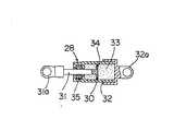
図6において、前記両アーム12、29との間に振動吸収緩衝装置28として、緩衝ダンパーが設けられ、エンジンの回転方向の振動と、前記弾性装置の弾性体に回転方向の振れがかかることにより生ずる弾性体の反発力を抑えて緩和できる。該緩衝ダンパー28として、オイルダンパーが装着されている。エンジン側の取付けたアーム12の先端支持部12aの支軸にオイルダンパー28のピストン30のロッド31の基端部31aを回動自由に軸支し、かつ機体に取付ける側のアーム29の先端支持部29aの支軸にオイルダンパー28のシリンダ32の基端32aを回動自由に軸支し、シリンダ32に所定容量のオイル室33を構成し、そのピストン30にオリフィス34が設けられ、エンジンの回転方向の振動、或いは弾性体に生ずる反発力がピストン30にかかることにより、オイル室33のオイルがオリフィス34を通じてピストンの左側又は右側に移行して、エンジンの振動を吸収緩和できるようにしてある。なお、ピストンロッド31とシリンダ32との間にオイルシール35が設けられ、シリンダ32のオイルが洩れないよいうにしてある。上記実施形態で、緩衝ダンパー28として、オイルダンパーの場合を説明したが、これに限られるものではなく、緩衝手段として例えばエアーダンパー、ばね等を用いることもできる。緩衝手段である緩衝ダンパー28は、図1ないし図6に示すように、後部側振動吸収弾性装置の固定外輪25の上方に位置している。
【0017】
エンジンの振動を前記環状ラバー27と緩衝ダンパー28で吸収緩和する作用について説明する。単気筒のエンジンでは、エンジンのアイドリング時等の低速回転時、高速回転時等において、振動が生ずるが、その振動をエンジン本体1の両端の支持部に備えた環状ラバー23、27の弾性で吸収させ、かつ回転方向の振動と、ラバー23、27に生ずる反発力がアーム29とアーム12間の油圧ダンパー28に作用してピストン30をシリンダ32に進退させ、ピストン30のオリフィス34を通じてオイル室3のオイルが左右に移行されオイルにより吸収し、エンジンの振動を吸収緩和することができる。
【0018】
以上の実施形態では、エンジン本体の軸方向の前後部の支承部に振動吸収弾性装置を備え、その後部の支承部に関連して振動吸収緩衝装置を設けた場合を示したが、これに限られるものではなく、エンジン本体の軸方向の前部は支承部が可動自由な支承構造として後部のみに振動吸収弾性装置を設け、その支承部に関連して振動吸収緩衝装置を設けて振動吸収緩和を図ることができる。この発明はこの形態に限られるものではなく、この発明の要旨を逸脱しない範囲で、様々な形態を実施しうるものである。
【0019】
【発明の効果】
この発明の模型飛行機用エンジンによれば、低速回転時等のエンジンの振動をラバー等弾性体を介在した振動吸収弾性装置で振動を吸収するとともにエンジンの振動と、弾性体の反発力を振動吸収緩衝装置で吸収緩和できる。従って、振動吸収弾性装置と振動吸収緩衝装置との相乗効果により低速回転のみならず高速回転時のエンジンの振動を吸収することができるので、機体に振動が伝わるのを防ぐことができ、安定した飛行を保つことができ、かつ飛行機の各種装置の故障や、異常の発生を防ぐことができる。
【0020】
この発明によれば、エンジン本体の出力軸方向の前後2ヵ所に設けた支承部の前部側と後部側の振動吸収弾性装置で上下方向、回転方向の振動を吸収でき、かつエンジン本体後部の支承部に備えた振動吸収緩衝装置によりエンジンの振動と弾性体に生ずる反発力を吸収緩和しうるようにしたので、低速回転時、高速回転時のエンジンの振動を振動吸収弾性装置と振動吸収緩衝装置との相乗効果で完全に吸収緩和することができ、機体に振動が伝わるのを防ぎ、安定した飛行を保つことができ、飛行機の各種装置の故障や、異常の発生を防ぐことができる。
【0021】
この発明によれば、低速回転時等のエンジンに生ずる上下方向、回転方向の振動をラバー等弾性体で吸収するとともに回転方向の振動と弾性体に生ずる反発力を油圧ダンパー等緩衝ダンパーで吸収緩和できる。従って、低速回転のみならず高速回転時のエンジンの振動をラバー等弾性体と油圧ダンパー等緩衝ダンパーで完全に吸収緩和することができる。
【図面の簡単な説明】
【図1】この発明の防振装置付き模型飛行機用エンジンを示す一部破断正面図である。
【図2】同平面図である。
【図3】同右側面図である。
【図4】後部の振動吸収弾性装置を備えた支承部を取外した状態の右側面図である。
【図5】同一部破断左側面図である。
【図6】油圧ダンパーの断面図である。
【符号の説明】
1…エンジン本体、10…環状支持部、12…アーム、14…支承軸、20…振動吸収弾性装置、21…固定外輪、22…取付け部、23…環状ラバー、24…振動吸収弾性装置、25…固定外輪、26…取付け部、27…環状ラバー、28…振動吸収緩衝装置、29…アーム、30…ピストン、31…ロッド、32…シリンダ、33…オイル室、34…オリフィス、A…機体の設置部。[0001]
BACKGROUND OF THE INVENTION
The present invention relatesto a model airplane engine equipped with avibration isolator that absorbs and reduces vibrations generated in an engine of a model airplane or the like to reduce vibrations transmitted to the airframe.
[0002]
[Prior art]
In the conventional model airplane, the model engine is ignited and exploded once every two rotations with a single cylinder, so there is always unevenness in the vertical movement of the piston of the engine, and the unevenness constantly vibrates in the vertical and rotational directions of the engine. Is produced. Conventionally, when installing this single-cylinder engine on an airplane body, the installation part of the engine body is installed directly on the body with a mounting bracket, or an elastic material such as rubber, a spring material or the like is sandwiched between them.
[0003]
[Problems to be solved by the invention]
Conventionally, in order to reduce the vibration of the engine, there is a type in which an elastic material such as a rubber is used for the mounting portion when the engine body is fixed. If soft rubber is used at that time, the effect is high at high speeds, but the engine body shakes greatly at low speeds with large torque fluctuations.For example, it is not possible to stop the engine from shaking greatly during idling. Become. If the rubber is too hard, vibrations cannot be absorbed when the engine rotates, and therefore abnormalities and malfunctions are likely to occur in the aircraft body and various devices due to severe engine vibrations such as when idling. If it cannot be absorbed, the flight balance will be lost, which is a problem.
[0004]
The present invention solves such problems, and includes a vibration-absorbing elastic device incorporating an elastic body such as a rubber between a support portion of the engine main body and an installation portion of the airframe, an arm of the support portion of the engine main body, and the airframe side. of comprising avibration damping device comprising a vibration absorbing buffer apparatus between the arms of the fixing means to absorb alleviate vibration of the engine in the buffer damper elastic body and the vibration absorbing buffer apparatus for the vibration absorbing elastic device, low-speed rotation, An object of the present invention is to provide amodel airplane engine that can alleviate vibrations of the airframe during high-speed rotation, maintain stable flight, and prevent failure and the like. In addition, the vibration absorption elastic device with a built-in rubber is provided at two positions in the front and rear in the axial direction of the engine body, and the vibration absorption buffer device is provided in relation to the vibration absorption elastic device at the rear part thereof, so that the vibration can be effectively applied. An object of the present invention is to provide amodel airplane engine that can absorb and relax.
[0005]
[Means for solving the problems]
Theengine for amodel airplane according to claim 1 of the present invention is amodel airplaneengineattached to a model airplane body,
The engine includes an engine body, and a support portion at each of a front portion and a rear portion of the engine body,
The front support portion is a front portion of the engine main body and is provided on the same axis as the output shaft of the engine main body, and is located on the outer periphery of the annular support portion. A front-side vibration absorbing elastic device comprising a fixed outer ring for fixing to the ring, and an annular elastic body interposed between the annular support portion and the fixed outer ring,
The rear support portion is a rear portion of the engine main body, is provided on the same axis as the output shaft of the engine main body, is located on the outer periphery of the support shaft, and is fixed to the installation portion of the airframe. A rear-side vibration absorbing elastic device that is configured by a fixed outer ring and an annular elastic body that is interposed between the bearing shaft and the fixed outer ring and can absorb vibrations of the engine,
Further, the engine causes the arm of the fixed outer ring of the rear side vibration absorbing and elastic device and the arm of the rear part of the engine body to face each other in a direction perpendicular to the axis of the output shaft of the engine. And a vibration absorbing shock absorber provided with a shock absorbing means for absorbing the engine vibration and the repulsive force generated in the elastic body between the arms, and the front vibration absorbing elastic device for the engine vibration, Absorption is performed by the rear side vibration absorption elastic device and the vibration absorption buffer device .
[0006]
The operationof the structure of thepresent invention is achieved by providing two vibration absorption elastic devices on thefront side and the rear side in the output shaft direction of the engine body, and using a vibration absorption buffer device in combination with therear side vibration absorption elastic device.The vibration absorbing elastic deviceon the front side and the rear side can absorb vibrations in the vertical and rotational directions of the engine during low speed rotation and the like, and the arm of the vibration absorbing elastic device fixed to the fuselage and attached to the engine body Vibration absorption shock absorbers consisting of shock absorbers such as hydraulic dampers and air dampers between arms can absorb and mitigate vibrations in the rotating direction and repulsive forces generated in elastic bodies, preventing vibrations from being transmitted to the aircraft Flight can be maintained, and it is possible to prevent malfunctions and abnormalities of various aircraft devices.
[0007]
The invention according to
[0008]
According to the present invention, as the vibration absorbing elastic device, an elastic body such as a rubber is interposed between the bearing portion of the engine body and a fixed outer ring fixed to the fuselage, and the bearing portion of the engine body is used as the vibration absorbing buffer device. And an arm provided on a fixed outer ring on the outer periphery of the vibration-absorbing elastic device are connected by a buffer damper such as an oil cylinder or an air cylinder.
[0009]
Action byinventions of the structureof this is the vertical direction occurring in the engine during low-speed rotation, absorption relaxation in buffer damper vibration and repulsive force generated in the elastic member in the rotational direction as well as absorbing the vibration in the rotating direction with a rubber or the like elastic body it can. Therefore, the vibration of the engine can be completely absorbed and relaxed.
[0010]
A third aspect of the present invention is the model airplane engine according to the first aspect, wherein the buffer means is located above the fixed outer ring of the rear vibration absorbing elastic device.
According to a fourth aspect of the present invention, the vibration absorbing buffer device includesan arm provided on thefixedouter ring of therear vibration absorbing elastic deviceand an arm fixed to the support portion of the engine body. 2. The model airplane engine according to claim 1, wherein the engine is provided so as to be opposed to each other in a direction perpendicular to the axis with the axis of the shaft as a fulcrum .
[0011]
DETAILED DESCRIPTION OF THE INVENTION
An embodiment of the present invention will be described with reference to the drawings. 1 is a partially cutaway front view showing amodel airplane engine with a vibration isolator of the present invention, FIG. 2 is a plan view thereof, FIG. 3 is a right side view thereof, and FIG. 4 is a support equipped with a vibration absorbing elastic device at the rear. FIG. 5 is a left side view with the same part broken, and FIG. 6 is a cross-sectional view of the hydraulic damper.
[0012]
1 to 5, reference numeral 1 denotes a single-cylinder model airplane engine body, which is a
[0013]
The engine includes an engine main body 1 and support portions on each of a front portion and a rear portion of the engine main body 1. The bearing portion at the front portion in the axial direction of the engine body 1 is provided with an annular bearing
[0014]
The fixed
[0015]
At the rear part of the engine body 1, a
[0016]
In FIG. 6, a
[0017]
The action of absorbing and mitigating engine vibration by the
[0018]
In the above embodiment, the case where the vibration absorption elastic device is provided in the front and rear support portions in the axial direction of the engine body and the vibration absorption buffer device is provided in relation to the rear support portion is shown. The front part of the engine body in the axial direction is not supported, and the vibration absorption elastic device is provided only in the rear part as a support structure in which the support part is movable, and the vibration absorption buffer device is provided in relation to the support part to reduce vibration absorption. Can be achieved. The present invention is not limited to this embodiment, and various embodiments can be implemented without departing from the gist of the present invention.
[0019]
【The invention's effect】
According tothe model airplane engine of the present invention, the vibration of the engine during low-speed rotation or the like is absorbed by the vibration-absorbing elastic device having an elastic body such as rubber, and the vibration of the engine and the repulsive force of the elastic body are absorbed. Absorption can be reduced with a shock absorber. Therefore, the vibration of the engine can be absorbed not only at low speed but also at high speed by the synergistic effect of the vibration absorbing elastic device and the vibration absorbing buffer device, so that the vibration can be prevented from being transmitted to the airframe and stable. It is possible to keep the flight, and it is possible to prevent malfunctions and abnormalities of various aircraft devices.
[0020]
According to thepresent invention, vibrations in the vertical and rotational directions can be absorbed bythe vibration absorbing elastic deviceson the front side and the rear side of thesupport portion provided at twofront and rear positions in the output shaft direction of the engine main body, and the rear of the engine main body can be absorbed. The vibration absorption shock absorber provided in the support part can absorb and mitigate engine vibration and the repulsive force generated in the elastic body. Therefore, the vibration absorption elastic device and vibration absorption buffer absorb the vibration of the engine at low speed and high speed. A synergistic effect with the device can completely absorb and relieve vibration, prevent vibrations from being transmitted to the aircraft, maintain stable flight, and prevent malfunctions and abnormalities of various aircraft devices.
[0021]
According to thepresent invention, vibrations in the vertical and rotational directions generated in the engine during low speed rotation and the like are absorbed by the elastic body such as rubber, and the vibrations in the rotational direction and the repulsive force generated in the elastic body are absorbed and reduced by the buffer damper such as the hydraulic damper. it can. Therefore, the vibration of the engine not only at low speed but also at high speed can be completely absorbed and relaxed by an elastic body such as rubber and a buffer damper such as a hydraulic damper.
[Brief description of the drawings]
1 is a partially cutaway front view showing the vibration isolating device withmodel-type airplane engine of the present invention.
FIG. 2 is a plan view of the same.
FIG. 3 is a right side view of the same.
FIG. 4 is a right side view of a state in which a support portion having a rear vibration absorbing elastic device is removed.
FIG. 5 is a left side view of the same part broken away.
FIG. 6 is a cross-sectional view of a hydraulic damper.
[Explanation of symbols]
DESCRIPTION OF SYMBOLS 1 ... Engine main body, 10 ... Ring support part, 12 ... Arm,14 ... Bearing shaft, 20 ... Vibration absorption elastic device, 21 ...Fixed outer ring, 22 ... Mounting part, 23 ... Ring rubber, 24 ... Vibration absorption elastic device, 25 ...fixed outer ring, 26 ... mounting portion, 27 ... annular rubber, 28 ... vibration absorbing shock absorber, 29 ... arm, 30 ... piston, 31 ... rod, 32 ... cylinder, 33 ... oil chamber, 34 ... orifice, A ... of the fuselage Installation department.
Claims (4)
Translated fromJapanese該エンジンは、エンジン本体と、該エンジン本体の前部および後部のそれぞれに支承部を備え、 The engine includes an engine main body, and a support portion at each of the front and rear portions of the engine main body,
該前部の支承部は、前記エンジン本体の前部であり前記エンジン本体の出力軸と同一軸線上に設けられた環状支承部と、前記環状支承部の外周に位置し、前記機体の設置部への固定のための固定外輪と、前記環状支承部と前記固定外輪との間に介在する環状の弾性体とにより構成される前部側振動吸収弾性装置を備え、 The front support portion is a front portion of the engine main body and is provided on the same axis as the output shaft of the engine main body, and is located on the outer periphery of the annular support portion. A front-side vibration absorbing elastic device comprising a fixed outer ring for fixing to the ring, and an annular elastic body interposed between the annular support portion and the fixed outer ring,
前記後部の支承部は、前記エンジン本体の後部であり該エンジン本体の出力軸と同一軸線上に設けられた支承軸と、前記支承軸の外周に位置し、前記機体の設置部への固定のための固定外輪と、前記支承軸と前記固定外輪との間に介在し、前記エンジンの振動を吸収しうる環状の弾性体とにより構成される後部側振動吸収弾性装置を備え、 The rear support portion is a rear portion of the engine main body, is provided on the same axis as the output shaft of the engine main body, is located on the outer periphery of the support shaft, and is fixed to the installation portion of the airframe. A rear-side vibration absorbing elastic device that is configured by a fixed outer ring and an annular elastic body that is interposed between the bearing shaft and the fixed outer ring and can absorb vibrations of the engine,
さらに、前記エンジンは、前記後部側振動吸収弾性装置の前記固定外輪のアームと前記エンジン本体の後部のアームとを前記エンジンの前記出力軸の軸線とは直交する方向に接離可能に相対向させて備え、かつ、該両アーム間にエンジンの振動と弾性体に生ずる反発力を吸収する緩衝手段を備えてなる振動吸収緩衝装置を備え、前記エンジンの振動を前記前部側振動吸収弾性装置、前記後部側振動吸収弾性装置および前記振動吸収緩衝装置により吸収するようにしたこと特徴とする模型飛行機用エンジン。 Further, the engine causes the arm of the fixed outer ring of the rear side vibration absorbing and elastic device and the arm of the rear part of the engine body to face each other in a direction perpendicular to the axis of the output shaft of the engine. And a vibration absorbing shock absorber provided with a shock absorbing means for absorbing the engine vibration and the repulsive force generated in the elastic body between the arms, and the front vibration absorbing elastic device for the engine vibration, A model airplane engine characterized by absorbing the rear side vibration absorbing elastic device and the vibration absorbing buffer device.
Priority Applications (2)
| Application Number | Priority Date | Filing Date | Title |
|---|---|---|---|
| JP28275197AJP3923619B2 (en) | 1997-09-30 | 1997-09-30 | Model airplane engine |
| US09/058,766US6036163A (en) | 1997-09-30 | 1998-04-11 | Vibration-proof system for a model-craft engine |
Applications Claiming Priority (2)
| Application Number | Priority Date | Filing Date | Title |
|---|---|---|---|
| JP28275197AJP3923619B2 (en) | 1997-09-30 | 1997-09-30 | Model airplane engine |
| US09/058,766US6036163A (en) | 1997-09-30 | 1998-04-11 | Vibration-proof system for a model-craft engine |
Publications (2)
| Publication Number | Publication Date |
|---|---|
| JPH11101305A JPH11101305A (en) | 1999-04-13 |
| JP3923619B2true JP3923619B2 (en) | 2007-06-06 |
Family
ID=26554756
Family Applications (1)
| Application Number | Title | Priority Date | Filing Date |
|---|---|---|---|
| JP28275197AExpired - Fee RelatedJP3923619B2 (en) | 1997-09-30 | 1997-09-30 | Model airplane engine |
Country Status (2)
| Country | Link |
|---|---|
| US (1) | US6036163A (en) |
| JP (1) | JP3923619B2 (en) |
Families Citing this family (8)
| Publication number | Priority date | Publication date | Assignee | Title |
|---|---|---|---|---|
| EP1477658B1 (en)* | 2002-02-20 | 2013-06-19 | Yamaha Hatsudoki Kabushiki Kaisha | Engine fastening structure |
| ES2424945T3 (en)* | 2002-02-20 | 2013-10-10 | Yamaha Hatsudoki Kabushiki Kaisha | Motor fixing structure |
| US6779755B1 (en)* | 2003-03-20 | 2004-08-24 | Helge K. Thomsen | Adjustable mount for a model airplane engine |
| US8091833B2 (en) | 2008-02-29 | 2012-01-10 | Insitu, Inc. | Vibration isolation devices and associated systems and methods |
| WO2010099437A1 (en)* | 2009-02-27 | 2010-09-02 | Silk Road Medical, Inc. | Vessel closure clip device |
| US20140251088A1 (en)* | 2013-03-07 | 2014-09-11 | Egoink Limited | Tattoo machine |
| JP2017194098A (en)* | 2016-04-19 | 2017-10-26 | オイレス工業株式会社 | Seismic isolator |
| CN115717640B (en)* | 2022-12-09 | 2025-07-11 | 成都纵横大鹏无人机科技有限公司 | Aircraft engine vibration reduction device |
Family Cites Families (4)
| Publication number | Priority date | Publication date | Assignee | Title |
|---|---|---|---|---|
| US4634081A (en)* | 1983-12-30 | 1987-01-06 | The Boeing Company | Aft engine mount with vibration isolators |
| US5065959A (en)* | 1989-11-21 | 1991-11-19 | The Boeing Company | Vibration damping aircraft engine attachment |
| US5609312A (en)* | 1991-09-30 | 1997-03-11 | Arlton; Paul E. | Model helicopter |
| US5303896A (en)* | 1992-11-12 | 1994-04-19 | Sterka William E | Model airplane engine mounting system |
- 1997
- 1997-09-30JPJP28275197Apatent/JP3923619B2/ennot_activeExpired - Fee Related
- 1998
- 1998-04-11USUS09/058,766patent/US6036163A/ennot_activeExpired - Fee Related
Also Published As
| Publication number | Publication date |
|---|---|
| JPH11101305A (en) | 1999-04-13 |
| US6036163A (en) | 2000-03-14 |
Similar Documents
| Publication | Publication Date | Title |
|---|---|---|
| JP3923619B2 (en) | Model airplane engine | |
| JPH09504353A (en) | Torsional vibration damping device | |
| US6089121A (en) | Rotational vibration damper | |
| JPS61215830A (en) | Flywheel equipped with dynamic damper | |
| JP3836606B2 (en) | Anti-vibration tool holder | |
| JPS587071Y2 (en) | Vibration absorption device in centrifugal governor | |
| US7305959B2 (en) | Intake manifold with low chatter shaft system | |
| US2201932A (en) | Method of assembling vibration dampers | |
| KR100358515B1 (en) | Dual mass vibration damping flywheel for vehicles | |
| JP2001159448A (en) | Isolation damper pulley | |
| JPH018753Y2 (en) | ||
| KR100533462B1 (en) | Roll rod system of automobile | |
| JPH0531304Y2 (en) | ||
| JPH0124445Y2 (en) | ||
| JP4867960B2 (en) | Dynamic damper | |
| KR100440023B1 (en) | Balance shaft apparatus | |
| KR101043554B1 (en) | Automotive Damping Double Flywheels | |
| JPS626893Y2 (en) | ||
| CN222946492U (en) | Ball head device, suspension system and vehicle | |
| JPS6311406Y2 (en) | ||
| CN216895547U (en) | Centrifugal pendulum type dual-mass flywheel assembly | |
| JPH0210348Y2 (en) | ||
| CN212297415U (en) | A compound crankshaft shock absorber | |
| CN212003991U (en) | Support device for motor bearing protection | |
| CN113631827B (en) | Vibration dampers and/or absorbers |
Legal Events
| Date | Code | Title | Description |
|---|---|---|---|
| A621 | Written request for application examination | Free format text:JAPANESE INTERMEDIATE CODE: A621 Effective date:20040603 | |
| A977 | Report on retrieval | Free format text:JAPANESE INTERMEDIATE CODE: A971007 Effective date:20060519 | |
| A131 | Notification of reasons for refusal | Free format text:JAPANESE INTERMEDIATE CODE: A131 Effective date:20060627 | |
| A521 | Request for written amendment filed | Free format text:JAPANESE INTERMEDIATE CODE: A523 Effective date:20060825 | |
| TRDD | Decision of grant or rejection written | ||
| A01 | Written decision to grant a patent or to grant a registration (utility model) | Free format text:JAPANESE INTERMEDIATE CODE: A01 Effective date:20070213 | |
| A61 | First payment of annual fees (during grant procedure) | Free format text:JAPANESE INTERMEDIATE CODE: A61 Effective date:20070222 | |
| R150 | Certificate of patent or registration of utility model | Free format text:JAPANESE INTERMEDIATE CODE: R150 | |
| FPAY | Renewal fee payment (event date is renewal date of database) | Free format text:PAYMENT UNTIL: 20130302 Year of fee payment:6 | |
| FPAY | Renewal fee payment (event date is renewal date of database) | Free format text:PAYMENT UNTIL: 20160302 Year of fee payment:9 | |
| LAPS | Cancellation because of no payment of annual fees |