JP3922476B2 - Tabletop cutting machine - Google Patents
Tabletop cutting machineDownload PDFInfo
- Publication number
- JP3922476B2 JP3922476B2JP20804897AJP20804897AJP3922476B2JP 3922476 B2JP3922476 B2JP 3922476B2JP 20804897 AJP20804897 AJP 20804897AJP 20804897 AJP20804897 AJP 20804897AJP 3922476 B2JP3922476 B2JP 3922476B2
- Authority
- JP
- Japan
- Prior art keywords
- turntable
- base
- operation handle
- bevel
- circular saw
- Prior art date
- Legal status (The legal status is an assumption and is not a legal conclusion. Google has not performed a legal analysis and makes no representation as to the accuracy of the status listed.)
- Expired - Fee Related
Links
- 230000007246mechanismEffects0.000claimsdescription117
- 239000000463materialSubstances0.000description32
- 230000004048modificationEffects0.000description7
- 238000012986modificationMethods0.000description7
- 239000002023woodSubstances0.000description5
- 230000007935neutral effectEffects0.000description3
- 208000027418Wounds and injuryDiseases0.000description2
- 230000006835compressionEffects0.000description2
- 238000007906compressionMethods0.000description2
- 230000006378damageEffects0.000description2
- 208000014674injuryDiseases0.000description2
- 238000009434installationMethods0.000description2
- 230000001105regulatory effectEffects0.000description2
- 230000035807sensationEffects0.000description2
- 125000002066L-histidyl groupChemical group[H]N1C([H])=NC(C([H])([H])[C@](C(=O)[*])([H])N([H])[H])=C1[H]0.000description1
- 230000005540biological transmissionEffects0.000description1
- 230000000694effectsEffects0.000description1
- 230000002452interceptive effectEffects0.000description1
- 238000000034methodMethods0.000description1
Images


Classifications
- B—PERFORMING OPERATIONS; TRANSPORTING
- B27—WORKING OR PRESERVING WOOD OR SIMILAR MATERIAL; NAILING OR STAPLING MACHINES IN GENERAL
- B27B—SAWS FOR WOOD OR SIMILAR MATERIAL; COMPONENTS OR ACCESSORIES THEREFOR
- B27B5/00—Sawing machines working with circular or cylindrical saw blades; Components or equipment therefor
- B27B5/29—Details; Component parts; Accessories
- B—PERFORMING OPERATIONS; TRANSPORTING
- B23—MACHINE TOOLS; METAL-WORKING NOT OTHERWISE PROVIDED FOR
- B23D—PLANING; SLOTTING; SHEARING; BROACHING; SAWING; FILING; SCRAPING; LIKE OPERATIONS FOR WORKING METAL BY REMOVING MATERIAL, NOT OTHERWISE PROVIDED FOR
- B23D45/00—Sawing machines or sawing devices with circular saw blades or with friction saw discs
- B23D45/04—Sawing machines or sawing devices with circular saw blades or with friction saw discs with a circular saw blade or the stock carried by a pivoted lever
- B23D45/042—Sawing machines or sawing devices with circular saw blades or with friction saw discs with a circular saw blade or the stock carried by a pivoted lever with the saw blade carried by a pivoted lever
- B23D45/044—Sawing machines or sawing devices with circular saw blades or with friction saw discs with a circular saw blade or the stock carried by a pivoted lever with the saw blade carried by a pivoted lever the saw blade being adjustable according to angle of cut
- B—PERFORMING OPERATIONS; TRANSPORTING
- B23—MACHINE TOOLS; METAL-WORKING NOT OTHERWISE PROVIDED FOR
- B23D—PLANING; SLOTTING; SHEARING; BROACHING; SAWING; FILING; SCRAPING; LIKE OPERATIONS FOR WORKING METAL BY REMOVING MATERIAL, NOT OTHERWISE PROVIDED FOR
- B23D47/00—Sawing machines or sawing devices working with circular saw blades, characterised only by constructional features of particular parts
- B23D47/02—Sawing machines or sawing devices working with circular saw blades, characterised only by constructional features of particular parts of frames; of guiding arrangements for work-table or saw-carrier
- B23D47/025—Sawing machines or sawing devices working with circular saw blades, characterised only by constructional features of particular parts of frames; of guiding arrangements for work-table or saw-carrier of tables
- Y—GENERAL TAGGING OF NEW TECHNOLOGICAL DEVELOPMENTS; GENERAL TAGGING OF CROSS-SECTIONAL TECHNOLOGIES SPANNING OVER SEVERAL SECTIONS OF THE IPC; TECHNICAL SUBJECTS COVERED BY FORMER USPC CROSS-REFERENCE ART COLLECTIONS [XRACs] AND DIGESTS
- Y10—TECHNICAL SUBJECTS COVERED BY FORMER USPC
- Y10T—TECHNICAL SUBJECTS COVERED BY FORMER US CLASSIFICATION
- Y10T83/00—Cutting
- Y10T83/768—Rotatable disc tool pair or tool and carrier
- Y10T83/7684—With means to support work relative to tool[s]
- Y10T83/7693—Tool moved relative to work-support during cutting
- Y10T83/7697—Tool angularly adjustable relative to work-support
- Y—GENERAL TAGGING OF NEW TECHNOLOGICAL DEVELOPMENTS; GENERAL TAGGING OF CROSS-SECTIONAL TECHNOLOGIES SPANNING OVER SEVERAL SECTIONS OF THE IPC; TECHNICAL SUBJECTS COVERED BY FORMER USPC CROSS-REFERENCE ART COLLECTIONS [XRACs] AND DIGESTS
- Y10—TECHNICAL SUBJECTS COVERED BY FORMER USPC
- Y10T—TECHNICAL SUBJECTS COVERED BY FORMER US CLASSIFICATION
- Y10T83/00—Cutting
- Y10T83/768—Rotatable disc tool pair or tool and carrier
- Y10T83/7684—With means to support work relative to tool[s]
- Y10T83/7701—Supporting surface and tool axis angularly related
- Y10T83/7705—Adjustable angular relationship
- Y—GENERAL TAGGING OF NEW TECHNOLOGICAL DEVELOPMENTS; GENERAL TAGGING OF CROSS-SECTIONAL TECHNOLOGIES SPANNING OVER SEVERAL SECTIONS OF THE IPC; TECHNICAL SUBJECTS COVERED BY FORMER USPC CROSS-REFERENCE ART COLLECTIONS [XRACs] AND DIGESTS
- Y10—TECHNICAL SUBJECTS COVERED BY FORMER USPC
- Y10T—TECHNICAL SUBJECTS COVERED BY FORMER US CLASSIFICATION
- Y10T83/00—Cutting
- Y10T83/869—Means to drive or to guide tool
- Y10T83/8773—Bevel or miter cut
- Y—GENERAL TAGGING OF NEW TECHNOLOGICAL DEVELOPMENTS; GENERAL TAGGING OF CROSS-SECTIONAL TECHNOLOGIES SPANNING OVER SEVERAL SECTIONS OF THE IPC; TECHNICAL SUBJECTS COVERED BY FORMER USPC CROSS-REFERENCE ART COLLECTIONS [XRACs] AND DIGESTS
- Y10—TECHNICAL SUBJECTS COVERED BY FORMER USPC
- Y10T—TECHNICAL SUBJECTS COVERED BY FORMER US CLASSIFICATION
- Y10T83/00—Cutting
- Y10T83/929—Tool or tool with support
- Y10T83/9457—Joint or connection
- Y10T83/9488—Adjustable
Landscapes
- Engineering & Computer Science (AREA)
- Mechanical Engineering (AREA)
- Life Sciences & Earth Sciences (AREA)
- Wood Science & Technology (AREA)
- Forests & Forestry (AREA)
- Sawing (AREA)
- Machine Tool Positioning Apparatuses (AREA)
Description
Translated fromJapanese【0001】
【発明の属する技術分野】
本発明は、ベースと、切断待機位置及び切断完了位置間を鋸刃の平面に沿って移動可能に、且つ、鋸刃の平面と直交する平面に沿って傾動可能に設けられる丸鋸本体とを有し、しかも、丸鋸本体の傾動の固定及び解除を行なうためのベベルロック機構、ターンテーブルのベースへの固定及び解除を行なうためのマイターロック機構及び丸鋸本体が一方から他方に傾動する際に、鋸刃が垂直に位置したときに、丸鋸本体の傾動を停止するための傾動停止機構のうちの少なくとも1つを備えた卓上切断機に関する。
【0002】
【従来の技術】
従来から広く普及されている卓上切断機の一例に関して、ベースと、切断待機位置及び切断完了位置間を鋸刃の平面に沿って移動可能に、且つ、鋸刃の平面と直交する平面に沿って傾動可能にベースに取り付けられた丸鋸本体と、丸鋸本体の傾動の固定及び解除を行なうためのベベルロック機構とを備えた卓上切断機が知られている。
【0003】
又、卓上切断機の他の一例に関して、ベースと、ベースに回動可能に取り付けられたターンテーブルと、切断待機位置及び切断完了位置間を鋸刃の平面に沿って移動可能に、且つ、鋸刃の平面と直交する平面に沿って傾動可能にターンテーブルに取り付けられた丸鋸本体と、ターンテーブルのベースへの固定及び解除を行なうためのマイターロック機構と、丸鋸本体の傾動の固定及び解除を行なうためのベベルロック機構とを備えた卓上切断機が知られている。
【0004】
卓上切断機の更に他の一例に関してベースと、切断待機位置及び切断完了位置間を鋸刃の平面に沿って移動可能に、且つ、鋸刃の平面と直交する平面に沿って傾動可能にベースに取り付けられた丸鋸本体と、丸鋸本体の傾動の固定及び解除を行なうためのベベルロック機構と、丸鋸本体が一方から他方に傾動する際に、鋸刃が垂直に位置したときに、丸鋸本体の傾動を停止するための傾動停止機構とを備えた卓上切断機が知られている。
【0005】
このような卓上切断機においては、丸鋸本体の傾動の固定及び解除は、ベベルロック操作ハンドルを操作することによって行なわれる。又、丸鋸本体が一方から他方に傾動する際に、鋸刃が垂直に位置すると、傾動停止機構によって、丸鋸本体の傾動が停止され、鋸刃は垂直な状態に保持される。このような状態から丸鋸本体を更に他方に傾動する際には、傾動停止操作ハンドルを操作することによって、傾動停止機構による丸鋸本体の傾動停止を解除する。
【0006】
【発明が解決しようとする課題】
しかしながら、上述した従来の卓上切断機においては、ベベルロック機構のためのベベルロック操作ハンドル及び傾動停止機構のための傾動停止操作ハンドルがベースの後方側に配置されているため、オペレータは、卓上切断機の後方側に移動して、これ等のハンドルを操作しなければならず、この操作は極めて厄介であった。
【0007】
又、オペレータは、自分自身を卓上切断機の前方側に位置した状態で、手をベースの後方側に伸ばし、これ等のハンドルを操作することも可能であるが、この場合には、ハンドルの位置を目視によって確認することが困難であり、従って、ハンドルの位置を手探りで確認した上で、その操作を行なわなければならず、操作性が著しく低下するという問題が生じていた。更に、このような操作を行なうために、手をベースの後方側に伸ばしたときに、鋸刃付近の部材に手を引っ掛けて怪我をする虞があり、特に、鋸刃の周りに安全カバーが設けられていない場合には、手が鋸刃に直接的に接触し、これにより大怪我をする虞があった。
【0008】
従って、本発明の目的は、ベベルロック機構及び/又は傾動停止機構の操作を極めて容易に、安全に且つ確実に行なうことが可能な卓上切断機を提供することにある。
【0009】
【課題を解決するための手段】
請求項1の本発明は、ベース(1)と、切断待機位置及び切断完了位置間を鋸刃(25)の平面に沿って移動可能に、且つ、前記ベース(1)に対して回転可能なブラケット(10)を用いて前記鋸刃(25)の平面と直交する平面に沿って傾動可能に前記ベース(1)の後方側に取り付けられた丸鋸本体(3)と、前記丸鋸本体(3)の傾動の固定及び解除を行なうためのベベルロック機構(8)とを備えた卓上切断機において、
前記ベベルロック機構(8)は、前記ベース(1)の前面側に配置されたベベルロック操作ハンドル(11)と、前記ベース(1)の前面側から後方側へ延びると共に前記ベース(1)に前記ブラケット(10)を押し付けるように前記ベベルロック操作ハンドル(11)によって移動可能なベベルロックシャフト(9)とを含むことを特徴としている。
【0010】
請求項2の本発明は、ベース(1)と、前記ベース(1)に回動可能に取り付けられたターンテーブル(2)と、切断待機位置及び切断完了位置間を鋸刃(25)の平面に沿って移動可能に、且つ、前記ターンテーブル(2)に対して回転可能なブラケット(10)を用いて前記鋸刃(25)の平面と直交する平面に沿って傾動可能に前記ターンテーブル(2)の後方側に取り付けられた丸鋸本体(3)と、前記ターンテーブル(2)の前記ベース(1)への固定及び解除を行なうためのマイターロック機構(4)と、前記丸鋸本体(3)の傾動の固定及び解除を行なうためのベベルロック機構(8)とを備えた卓上切断機において、
前記マイターロック機構(4)のためのマイターロック操作ハンドル(7)が前記ターンテーブル(2)の前面側に配置されており、
前記ベベルロック機構(8)は、前記ターンテーブル(2)の前面側に配置されたベベルロック操作ハンドル(11)と、前記ターンテーブル(2)の前面側から後方側へ延びると共に前記ターンテーブル(2)に前記ブラケット(10)を押し付けるように前記ベベルロック操作ハンドル(11)によって移動可能なベベルロックシャフト(9)とを含むことを特徴としている。
【0011】
請求項3の本発明は、請求項2の卓上切断機において、前記マイターロック機構(4)のためのマイターロックシャフト(5)と、前記ベベルロック機構(8)のためのベベルロックシャフト(9)とが、これ等が相互に接触しないように、保持手段(2c、23、24)を介して間隔をあけて同一軸心上に配置されており、
前記マイターロックシャフト(5)の一端に前記マイターロック操作ハンドル(7)が取り付けられ、前記ベベルロックシャフト(9)の一端に前記ベベルロック操作ハンドル(11)が取り付けられている
ことを特徴としている。
【0012】
請求項4の本発明は、ベース(1)と、切断待機位置及び切断完了位置間を鋸刃(25)の平面に沿って移動可能に、且つ、前記ベース(1)に対して回転可能なブラケット(10)を用いて前記鋸刃(25)の平面と直交する平面に沿って傾動可能に前記ベース(1)の後方側に取り付けられた丸鋸本体(3)と、前記丸鋸本体(3)の傾動の固定及び解除を行なうためのベベルロック機構(8)と、前記丸鋸本体(3)が一方から他方に傾動する際に、前記鋸刃(25)が垂直に位置したときに、前記丸鋸本体(3)の傾動を停止するための傾動停止機構(16)とを備えた卓上切断機において、
前記傾動停止機構(16)は、前記ベース(1)の前面側に配置された傾動停止操作ハンドル(18)と、前記ベース(1)の前面側から後方側へ延びると共に前記傾動停止操作ハンドル(18)によって回転可能な傾動停止シャフト(17)と、回転する前記ブラケット(10)が当たるように前記傾動停止シャフト(17)によって回転可能なロックピン(20)とを含むことを特徴としている。
【0013】
請求項5の本発明は、 ベース(1)と、前記ベース(1)に回動可能に取り付けられたターンテーブル(2)と、切断待機位置及び切断完了位置間を鋸刃(25)の平面に沿って移動可能に、且つ、前記ターンテーブル(2)に対して回転可能なブラケット(10)を用いて前記鋸刃(25)の平面と直交する平面に沿って傾動可能に前記ターンテーブル(2)の後方側に取り付けられた丸鋸本体(3)と、前記ターンテーブル(2)の前記ベース(1)への固定及び解除を行なうためのマイターロック機構(4)と、前記丸鋸本体(3)の傾動の固定及び解除を行なうためのベベルロック機構(8)と、前記丸鋸本体(3)が一方から他方に傾動する際に、前記鋸刃(25)が垂直に位置したときに、前記丸鋸本体(3)の傾動を停止するための傾動停止機構(16)とを備えた卓上切断機において、
前記マイターロック機構(4)のためのマイターロック操作ハンドル(7)が前記ターンテーブル(2)の前面側に配置されており、前記ベベルロック機構(8)のためのベベルロック操作ハンドル(11)が前記ターンテーブル(2)の前面側に配置されており、
前記傾動停止機構(16)は、前記ターンテーブル(2)の前面側に配置された傾動停止操作ハンドル(18)と、前記ターンテーブル(2)の前面側から後方側へ延びると共に前記傾動停止操作ハンドル(18)によって回転可能な傾動停止シャフト(17)と、回転する前記ブラケット(10)が当たるように前記傾動停止シャフト(17)によって回転可能なロックピン(20)とを含むことを特徴とする。
【0014】
以下、本発明の実施形態を示す図面に対応付けて本発明を説明する。但し、本発明は図示の形態に限定されない。
【0015】
【発明の実施の形態】
以下、図1乃至図12を参照して本発明の一実施形態を説明する。
【0016】
本発明の実施形態にかかる卓上切断機は、ベース1と、ターンテーブル2と、丸鋸本体3と、マイターロック機構4と、ベベルロック機構8と、傾動停止機構16からなっている。
【0017】
ベース1は、図2に示すように、4本の脚部1aを有しており、その中央の位置に円形状のターンテーブル載置部分1bを備えている。ベース1にはフェンス30が固定されており、このフェンス30に木材等の被切断材31を当接させることによって、その位置決めが行なわれる。ベース1におけるターンテーブル載置部分1bの周囲の一部には、ベース1に対するターンテーブル2の角度を表示するための角度目盛33が設けられている(図2参照)。
【0018】
ターンテーブル2は、図2に示すように、上記ベース1のターンテーブル載置部分1b上に載置され垂直方向に伸びる支軸12(図3及び図6参照)を介してベース1に回動可能に取り付けられた円形状部分2aと、この円形状部分2aの一端部に一体的に形成された矩形状部分2bとからなっている。円形状部分2aの下端は、ベース1のターンテーブル載置部分1bと接触して、リング状の接触摺動部分Aを形成している(図6参照)。このように構成されたターンテーブル2の上面には、矩形状部分2bの長さ方向に沿って、一対の刃口板32、32が間隔をあけて平行に取り付けられており、被切断材31を切断する際に、これ等一対の刃口板32、32間に鋸刃25の先端を挿入することができる。
【0019】
ターンテーブル2の円形状部分2aにおいて、矩形状部分2bが形成された側と反対側の位置には、ブラケット10が水平方向に伸びる支軸15を介して回動可能に取り付けられている(図3参照)。ブラケット10は、図10に示すように、一端に支軸15と直交する円形状の接触面10aを有しており、この接触面10aの中央部に支軸15を挿通するための貫通孔10dが形成されている。更に、上記接触面10aの外周の下方部分には、張出し部10bが一体的に形成されており、この張出し部10bには、支軸15の中心軸線を中心とする円の円周方向に伸びる長孔10cが形成されている。
【0020】
一方、上記ブラケット10が取り付けられるターンテーブル2の円形状部分2a、即ち、その円形状部分2aにおいて、矩形状部分2bが形成された側と反対側の位置には、図11に示すように、ブラケット10の上記円形状の接触面10aに合致する円形状の接触面2dが設けられており、この接触面2dの外周の下方部分には、張出し部2eが一体的に形成されている。この張出し部2eには、後述するベベルロック機構8のベベルロックシャフト9の先端部が螺合されるネジ孔14が形成されている。
【0021】
上述したブラケット10は、その円形状の接触面10aがターンテーブル2側の円形状の接触面2dに接触するように配置され、このような状態で、ブラケット10の貫通孔10dに支軸15を挿通し、この支軸15の先端をターンテーブル2側の円形状の接触面2dの中央部に形成されたネジ穴38に螺合する。
【0022】
このようにしてブラケット10はターンテーブル2に支軸15を介して揺動可能に取り付けられるが、このブラケット10には、図9に示すように、一対の揺動限界規制ネジ36、37が取り付けられており、これ等のネジ36、37は、これ等ネジ36、37間において、ターンテーブル2側に設けられたストッパ(図示せず)と当接することによって、ブラケット10の揺動範囲が規制されるように構成されている。勿論、ネジ36、37の螺合量を調節することによって、ブラケット10の揺動限界位置の微調整が行なわれる。
【0023】
上述したように、ターンテーブル2に揺動可能に取り付けられたブラケット10には、一対のリンク28、29を介して丸鋸本体3が図1及び図3において左右方向に移動可能に取り付けられている。図1及び図3において、27は、鋸刃25を回転させるためのモータ(図示せず)、このモータの出力軸を鋸刃25に伝達するための動力伝達機構(図示せず)等を内蔵したドライブユニットであり、3a及び3bは、丸鋸本体3にそれぞれ設けられた第1ハンドル及び第2ハンドルである。
【0024】
上述したベース1と、ターンテーブル2と、リンク28、29との組合せを採用することにより、丸鋸本体3は、ターンテーブル2と共に支軸12(図3参照)を中心として水平面に沿って回動可能である一方、ターンテーブル2とは独立して、支軸15を中心として垂直面に沿って回動可能であり、更に、この丸鋸本体3は、このような回動範囲内の任意の位置において、鋸刃25と同一平面に沿って、リンク28、29によって許容された所定ストロークの範囲内で移動可能である。即ち、丸鋸本体3は、切断待機位置及び切断完了位置間を鋸刃25の平面に沿って移動可能であると共に、鋸刃25の平面と直交する平面に沿って傾動可能である。
【0025】
従って、▲1▼鋸刃25を垂直に維持し、このように垂直に維持された鋸刃25が、フェンス30に対する被切断材31の当接面と直交するように、被切断材31の取付け位置を保持した状態で、鋸刃25をその平面方向に移動させれば、被切断材31を直角に切断することができ、▲2▼鋸刃25を垂直に維持し、このように垂直に維持された鋸刃25が、フェンス30に対する被切断材31の当接面と直交しないように、被切断材31の取付け位置を保持した状態で、鋸刃25をその平面方向に移動させれば、被切断材31その平面において斜めに切断することができ、▲3▼鋸刃25を垂直線に対して傾斜した状態に維持し、このように傾斜した状態に維持された鋸刃25が、フェンス30に対する被切断材31の当接面と直交するように、被切断材31の取付け位置を保持した状態で、鋸刃25をその平面方向に移動させれば、被切断材31をその側面において斜めに切断することができ、更に、▲4▼鋸刃25及び被切断材31の上述した配置を任意に組み合わせることによって、それぞれの組合せにかかる切断パターンに従った切断が可能である。
【0026】
上述したベース1とターンテーブル2との上述したリング状の接触摺動部分Aには、位置決め機構39が設けられている(図6参照)。
【0027】
位置決め機構39は、プランジャボア40と、プランジャ41と、調節機構42、弾性部材43と、複数個の凹部44とからなっている。
【0028】
即ち、プランジャボア40は、ターンテーブル2の円形状部分2aと矩形状部分2bとの間の位置において、上記接触摺動部分Aに臨むように、ターンテーブル2を垂直方向に貫通して設けられている。このプランジャボア40の上方部分には、図6に示すように、調節機構42のための雌ネジ部が形成されている。
【0029】
プランジャ41は、ボール型プランジャからなっており、プランジャボア40の上記接触摺動部分A側の一端から出没可能なようにプランジャボア40内に配置されている。
【0030】
調節機構42は、上端に六角穴を有する無頭の雄ネジからなっており、プランジャボア40の上方部分に形成された雌ネジ部に螺合されている。従って、雄ネジとして構成された調節機構42は、それ自身を回転させることによって、雌ネジ部内において、上下方向に移動可能である。
【0031】
弾性部材43は、圧縮コイルスプリングからなっており、調節機構42とプランジャ41との間に配置されており、プランジャ41を所定の弾性力で下方に押し付けている。
【0032】
複数個の凹部44は、上述したように弾性部材43によって下方に押し付けられたプランジャ41を受け入れることができるように、リング状の接触摺動部分Aに臨むように、ベース1にそれぞれ形成されている。従って、複数個の凹部44の各々における開口部の中心と支軸12の中心との間の距離は、相互に同一であり、この距離は、上述したプランジャ41の中心と支軸12の中心との間の距離と等しい。上述した複数個の凹部のうち、中央に位置する凹部44は、ターンテーブル2が中立位置に置かれているときに、プランジャ41を受け入れ、又、他の複数個の凹部44は、ターンテーブル2が中立位置から複数の異なる所定角度の何れかの角度をもって時計方向又は反時計方向に回動したときに、プランジャ41を受け入れるように構成されている。勿論、ターンテーブル2を中立位置に保持するための凹部44における開口部の中心及び支軸12の中心を結ぶ直線と、他の凹部44の各々における開口部の中心及び支軸12の中心を結ぶ直線との間の角度は、予め所望の値に設定されており、ターンテーブル2の回動角度は、ターンテーブル2に設けられたポインタPに基づいて、ベース1に設けられた角度目盛33によって読み取られる(図2参照)。
【0033】
上述した複数個の凹部44においては、その上部のみが開放されており、その下部は閉塞されている。従って、異物が凹部内に浸入することを回避することができる。
【0034】
上述した位置決め機構39によれば、雄ネジとして構成された調節機構42は、それ自身を回転させることによって、プランジャボア40の雌ネジ部内において、上下方向に移動可能であり、その結果、圧縮コイルスプリングからなる弾性部材43によるプランジャ41に付与される弾性力を調整することができるため、その弾性力をオペレータの好みの値に設定することができる。
【0035】
マイターロック機構4は、図4、図6及び図7から明らかなように、ターンテーブル2のベース1への固定及び解除を行なうもので、マイターロックシャフト5と、ロックレバー6と、マイターロック操作ハンドル7とからなっている。
【0036】
マイターロックシャフト5は、中空シャフトからなっており、ターンテーブル2の矩形状部分2b内にその長さ方向に沿って、且つ、その横方向において一方側に偏位して配置されている。このマイターロックシャフト5は、ターンテーブル2のリブ2cによって、その長さ方向に摺動可能に支持されている。
【0037】
ロックレバー6は、図6から明らかなように、一対の脚部6a、6bを有するように断面略U字状に形成されており、このロックレバー6は、脚部6aが下に、脚部6bが上にそれぞれ位置するように配置され、その一端部において、垂直方向に伸びるボルト45を介してターンテーブル2の裏面に、水平面に沿って揺動可能に取り付けられている。上記ロックレバー6の他端は、図6及び図7から明らかなように、上述したマイターロックシャフト5の先端に当接している。従って、マイターロックシャフト5がその軸線方向に沿って、卓上切断機の後方側に移動すると、ロックレバー6は、ボルト45を中心にして揺動し、ロックレバー6の下方の脚部6aの中央部分が、ターンテーブル2との接触摺動面Aを形成している、ベース1のリブ1cの側壁を押圧する。
【0038】
マイターロック操作ハンドル7は、図14に示すように、中空状に形成されており、カラー7a及びこれに一体的に形成されたねじ込みスリーブ7bを介して、上述したマイターロックシャフト5の後端に配置されている。即ち、マイターロック操作ハンドル7の内孔には、カラー7aが嵌め込まれ、これに固定されている。このカラー7aに一体的に形成されたねじ込みスリーブ7bは、ターンテーブル2の手前側端部の側壁2fに螺合されており、この状態において、ねじ込みスリーブ7bの先端は、マイターロックシャフト5の後端に当接している。このようにして、マイターロック操作ハンドル7は、ターンテーブル2の前面側に配置されている。
【0039】
従って、このマイターロック操作ハンドル7を回転させて、ねじ込みスリーブ7bをねじ込めば、マイターロックシャフト5が卓上切断機の後方側に移動し、これに伴なって、ロックレバー6は、ボルト45を中心にして揺動し、ロックレバー6の下方の脚部6aの中央部分がベース1のリブ1cの側壁を押圧し、このようにして、ターンテーブル2はベース1に固定される。
【0040】
ベベルロック機構8は、図4及び図7から明らかなように、丸鋸本体3の傾動の固定及び解除を行なうもので、ベベルロックシャフト9と、ベベルロック操作ハンドル11とからなっている。
【0041】
ベベルロックシャフト9は、図4に示すように、上述したマイターロックシャフト5内を通って、ターンテーブル2をその長さ方向に貫通している。即ち、ベベルロックシャフト9は、マイターロックシャフト5の内径よりも僅かに小さい外径及びターンテーブル2の全長よりも僅かに長い長さを有し、しかも、先端部がねじ切られたシャフトからなっている。このベベルロックシャフト9は、マイターロックシャフト5内を通し、ベベルロックシャフト9のねじ切られた先端部を、ターンテーブル2における張出し部2eに形成されたネジ孔14に螺合させ、更に、その先端部をブラケット10の張出し部10bに形成された長孔10cを通って外側に突出させることによって、ターンテーブル2に組み込まれている。ブラケット10の長孔10cから突出したベベルロックシャフト9の先端にはストッパリング13が取り付けられている。
【0042】
一方、ベベルロックシャフト9の後端には、ロックナット11aを介してベベルロック操作ハンドル11が固定されている。このようにして、ベベルロック操作ハンドル11は、ターンテーブル2の前面側において、上述したマイターロック操作ハンドル7と同一軸心的に配置されている。
【0043】
従って、このベベルロック操作ハンドル11を一方向に回転させれば、ブラケット10の張出し部10bがターンテーブル2側の張出し部2eに押し付けられ、丸鋸本体3の傾動が固定される。
【0044】
上述したようにマイターロックシャフト5とベベルロックシャフト9とは同一軸心上に配置されており、中空のマイターロックシャフト5の取付け位置は、ターンテーブル2のリブ2cによって確実に保持されている。従って、中空のマイターロックシャフト5の内径よりも十分に小さい外径を有するシャフトをベベルロックシャフト9として使用すれば、マイターロックシャフト5とベベルロックシャフト9との接触を確実に防止することができる。従って、ターンテーブル2のリブ2cは、マイターロックシャフト5とベベルロックシャフト9とが相互に接触しないように、これ等を間隔をあけて同一軸心上に配置するための保持手段として作用している。
【0045】
傾動停止機構16は、図5、図7及び図9から明らかなように、丸鋸本体3が一方から他方に傾動する際に、鋸刃25が垂直に位置したときに、丸鋸本体3の傾動を停止するためのもので、傾動停止シャフト17と、ストッパ手段22と、傾動停止操作ハンドル18とからなっている。
【0046】
傾動停止シャフト17は、ターンテーブル2の全長よりも僅かに長い長さを有しており、図7に示すように、この傾動停止シャフト17の先端部はクランク状に形成されている。即ち、傾動停止シャフト17の先端には、これに対して偏位したロックピン20がレバー19を介して取り付けられている。このように構成された傾動停止シャフト17は、図5及び図7に示すように、ベベルロックシャフト9と平行に配置され、傾動停止シャフト17の中心軸線を中心にして回動可能にターンテーブル2に支持されている。
【0047】
傾動停止シャフト17の一方向への回動限界位置は、これがターンテーブル2に設けられた突起21と当接することによって規制されている。即ち、傾動停止シャフト17のレバー19には切欠き部19aが形成されており、一方、ターンテーブル2の張出し部2e付近には、傾動停止シャフト17が回動して、そのロックピン20がブラケット10に形成された長孔10cを限定する円の円周上に位置したときに、上記切欠き部19aに当接する突起21が設けられている。
【0048】
又、傾動停止シャフト17には、上記突起21への切欠き部19aの当接状態を弾性的に保持するためのコイルスプリング34が取り付けられている。即ち、コイルスプリング34は、傾動停止シャフト17の周りに被せるように配置され、コイルスプリング34の一端を、傾動停止シャフト17に取付け、その他端をターンテーブル2側に取り付けることによって、傾動停止シャフト17を、図11において矢印Y方向に回転させるための弾性力を傾動停止シャフト17に付与するように構成されている。
【0049】
ストッパ手段22は、ボルト22a及びロックナット22bからなっており、丸鋸本体3が一方から他方に傾動する際に、鋸刃25が垂直に位置したときに(図9(a)参照)、上述した傾動停止シャフト17のロックピン20に当接可能なように、上述したブラケット10に取り付けられている。勿論、このストッパ手段22において、ボルト22aの螺合量を調節することによって、鋸刃25の位置の微調整を行なうことができる。
【0050】
傾動停止操作ハンドル18は、上述した傾動停止シャフト17の後端に取り付けられており、このようにして、傾動停止操作ハンドル18は、ターンテーブル2の前面側に配置されている。
【0051】
従って、丸鋸本体3が一方から他方に傾動する際に、鋸刃25が垂直に位置したときに、傾動停止機構16によって、丸鋸本体3の傾動が停止して、鋸刃25が垂直な状態に保持されるが、このような状態で、傾動停止操作ハンドル18をスプリング34に抗して回転させれば、丸鋸本体3の傾動の停止が解除され、丸鋸本体3の更なる傾動が可能になる。
【0052】
本発明の卓上切断機においては、ターンテーブル2の円形状部分2aの中央に支軸12が配置されている。従って、この支軸12との干渉を回避するために、マイターロックシャフト5、ベベルロックシャフト9及び傾動停止シャフト17を、ターンテーブル2の矩形状部分2bにおいて、その横方向に偏位するという基本的構造を採用し、これに伴なって、マイターロック機構4、ベベルロック機構8及び傾動停止機構16の各々は、上述した特別な構造を有している。
【0053】
次に、本発明の上述した卓上切断機の操作方法を以下に説明する。
【0054】
ターンテーブル2の回動角度を0°に維持し、且つ、鋸刃25の傾斜角度を0°に維持した状態で、直方体の木材からなる被切断材31を切断するという第1切断パターンを説明する。
【0055】
先ず、ベベルロック機構8によって鋸刃25の傾斜角度が0°に保持された状態で、ターンテーブル2の前面側に配置されたベベルロック操作ハンドル11を締め込んで、丸鋸本体3をリンク28、29及びブラケット10を介してターンテーブル2にロックする。
【0056】
次いで、ターンテーブル2の前面側に配置されたマイターロック操作ハンドル7を緩めて、ターンテーブル2のベース1への固定を解除し、この状態で、ターンテーブル2のポインタPを、ベース1の角度目盛33における0°に合わせるように、ターンテーブル2を回動させる。この際、位置決め機構39のプランジャ41は、接触摺動部分Aにおいて、ベース1に形成された凹部44内に受け入れられる。このようにプランジャ41が凹部44内に受け入れられるとき、クリック音を発生すると共に、その際の小さな衝撃力がオペレータに伝達され、角度目盛33における視覚的な感覚のみならず、クリック音による聴覚的な感覚、及び、このクリック音と共にオペレータに伝達される小さな衝撃力による触覚的な感覚によって、ターンテーブル2のベース1に対する回動角度が0°であることがオペレータに確実に認識される。このような状態でマイターロック操作ハンドル7を締め込んでターンテーブル2をベース1にロックする。被切断材31の1つの面(以下、「外側側面」という)をフェンス30に当接させ、この状態で、被切断材31を固定金具(図示せず)を介してベース1上に固定する。
【0057】
次いで、丸鋸本体3を図1に示すように最上位置、即ち、切断待機位置に保持した状態で、丸鋸本体3をターンテーブル2の手前側、即ち、図1の右側に移動させ、この状態で、モータ(図示せず)を駆動させて、鋸刃25を回転させ、丸鋸本体3を下方に押し付ける。このような丸鋸本体3の押付け動作に連動して、鋸刃25の周囲の露出部分を覆っている安全カバー26は丸鋸本体3のケーシング内に引っ込められ、鋸刃25の下半部が露出し、従って、被切断材31の手前側部分に切込みが入れられる。このように丸鋸本体3を下方に押し付け、これが最下位置に到達すると、鋸刃25の下端部分は、ターンテーブル2上に取り付けられた一対の刃口板32、32間に挿入される。
【0058】
上述した状態で、丸鋸本体3を下方に押し付けたまま、ターンテーブル2の後方側に移動させる(図3参照)。これによって、被切断材31は、その外側側面に対して垂直方向に真っ直ぐに切断され、換言すれば、被切断材31は、その平面において、外側側面における上方の辺(以下、「基準線」という)に対して垂直な切断線と、外側側面において、基準線に対して垂直な切断線とによって限定された切断面を有するように切断される。
【0059】
次に、ターンテーブル2の回動角度を0°以外の所望の角度、例えば、45°に維持し、且つ、鋸刃25の傾斜角度を0°に維持した状態で、直方体の木材からなる被切断材31を切断するという第2切断パターンを説明する。
【0060】
勿論、第2切断パターンにおいても、上述した第1切断パターンにおけると同様に、傾動停止機構16によって鋸刃25の傾斜角度が0°に保持された状態で、丸鋸本体3はリンク28、29及びブラケット10を介してターンテーブル2にロックされている。
【0061】
先ず、ターンテーブル2の前面側に配置されたマイターロック操作ハンドル7を緩めて、ターンテーブル2のベース1への固定を解除し、この状態で、ターンテーブル2のポインタPを、ベース1の角度目盛33における45°の角度に合わせるように、ターンテーブル2を回動させる。この際、位置決め機構39によって、第1切断パターンにおけると同様に、クリック音を発生すると共に、その際の小さな衝撃力がオペレータに伝達され、角度目盛33における視覚的な感覚のみならず、クリック音による聴覚的な感覚、及び、このクリック音と共にオペレータに伝達される小さな衝撃力による触覚的な感覚によって、ターンテーブル2のベース1に対する角度が所定の角度であることがオペレータに確実に認識される。このような状態で、ターンテーブル2の前面側に配置されたマイターロック操作ハンドル7を締め込んでターンテーブル2をベース1にロックする。上述した第1切断パターンにおけると同様に、被切断材31の1つの面をフェンス30に当接させ、この状態で、被切断材31を固定金具(図示せず)を介してベース1上に固定する。
【0062】
次いで、第1切断パターンにおけると同様に、丸鋸本体3を図1に示すように最上位置、即ち、切断待機位置に保持した状態で、丸鋸本体3をターンテーブル2の手前側、即ち、図1の右側に移動させ、この状態で、モータ(図示せず)を駆動させて、鋸刃25を回転させ、丸鋸本体3を下方に押し付ける。その結果、第1切断パターンにおけると同様に、被切断材31の手前側部分に切込みが入れられる。
【0063】
上述した状態で、丸鋸本体3を下方に押し付けたまま、ターンテーブル2の後方側に移動させる(図3参照)。これによって、被切断材31は、その平面において、基準線に対して斜めの切断線と、被切断材31の外側側面において、基準線に対して垂直な切断線とによって限定された切断面を有するように切断される。
【0064】
更に、ターンテーブル2の回動角度を0°に維持し、且つ、鋸刃25の傾斜角度を所望の角度、例えば、45°に維持した状態で、直方体の木材からなる被切断材31を切断するという第3切断パターンを説明する。
【0065】
勿論、第3切断パターンにおいても、上述した第1切断パターンにおけると同様に、ターンテーブル2のベース1に対する回動角度が0°である状態で、ターンテーブル2の前面側に配置されたマイターロック操作ハンドル7を締め込んでターンテーブル2がベース1にロックされている。
【0066】
先ず、ターンテーブル2の前面側に配置されたベベルロック操作ハンドル11を緩めて、鋸刃25の傾斜角度が45°の角度になるように丸鋸本体3を傾動させ、この状態で、ベベルロック操作ハンドル11を締め込んで、丸鋸本体3をリンク28、29及びブラケット10を介してターンテーブル2にロックする。
【0067】
勿論、鋸刃25が垂直な状態に位置するまでは、丸鋸本体3の傾動は自由に行なわれるが、鋸刃25が垂直な状態に位置したときに、傾動停止機構16によってその状態が保持され、換言すれば、鋸刃25の傾斜角度が0°に保持される。その場合には、傾動停止機構16の傾動停止操作ハンドル18を回転させることによって、鋸刃25の0°の傾斜角度の保持が解除され、更なる傾動が可能になる。上述した第1切断パターンにおけると同様に、被切断材31の1つの面をフェンス30に当接させ、この状態で、被切断材31を固定金具(図示せず)を介してベース1上に固定する。
【0068】
次いで、第1切断パターンにおけると同様に、丸鋸本体3を図1に示すように最上位置、即ち、切断待機位置に保持した状態で、丸鋸本体3をターンテーブル2の手前側、即ち、図1の右側に移動させ、この状態で、モータ(図示せず)を駆動させて、鋸刃25を回転させ、丸鋸本体3を下方に押し付ける。その結果、第1切断パターンにおけると同様に、被切断材31の手前側部分に切込みが入れられる。
【0069】
上述した状態で、丸鋸本体3を下方に押し付けたまま、ターンテーブル2の後方側に移動させる(図3参照)。これによって、被切断材31は、その平面において、基準線に対して垂直な切断線と、被切断材31の外側側面において、基準線に対して斜めの切断線とによって限定された切断面を有するように切断される。
【0070】
更に、ターンテーブル2の回動角度を0°以外の所望の角度、例えば、45°に維持し、且つ、鋸刃25の傾斜角度を0°以外の所望の角度、例えば、45°に維持した状態で、直方体の木材からなる被切断材31を切断するという第4切断パターンを説明する。
【0071】
先ず、第2切断パターンにおけると同様に、マイターロック操作ハンドル7を緩めて、ターンテーブル2のベース1への固定を解除し、この状態で、ターンテーブル2のポインタPを、ベース1の角度目盛33における45°の角度に合わせるように、ターンテーブル2を回動させる。このような状態でマイターロック操作ハンドル7を締め込んでターンテーブル2をベース1にロックする。
【0072】
次いで、第3切断パターンにおけると同様に、ベベルロック操作ハンドル11を緩めて、鋸刃25の傾斜角度が45°の角度になるように丸鋸本体3を傾動させ、この状態で、ベベルロック操作ハンドル11を締め込んで、丸鋸本体3をリンク28、29及びブラケット10を介してターンテーブル2にロックする。上述した第1切断パターンにおけると同様に、被切断材31の外側側面をフェンス30に当接させ、この状態で、被切断材31を固定金具(図示せず)を介してベース1上に固定する。
【0073】
次いで、第1切断パターンにおけると同様に、丸鋸本体3を図1に示すように最上位置、即ち、切断待機位置に保持した状態で、丸鋸本体3をターンテーブル2の手前側、即ち、図1の右側に移動させ、この状態で、モータ(図示せず)を駆動させて、鋸刃25を回転させ、丸鋸本体3を下方に押し付ける。その結果、第1切断パターンにおけると同様に、被切断材31の手前側部分に切込みが入れられる。
【0074】
上述した状態で、丸鋸本体3を下方に押し付けたまま、ターンテーブル2の後方側に移動させる(図3参照)。これによって、被切断材31は、その平面において、基準線に対して斜めの切断線と、被切断材31の外側側面において、基準線に対して斜めの切断線とによって限定された切断面を有するように切断される。
【0075】
本発明の上述した実施形態にかかる卓上切断機においては、ターンテーブル2のリブ2cが、マイターロックシャフト5とベベルロックシャフト9とが相互に接触しないように、これ等を間隔をあけて同一軸心上に配置するための保持手段として作用しているものとして説明したが(図12及び図13参照)、図15及び図16に示すように、マイターロックシャフト5とベベルロックシャフト9との間に、保持手段としてのベアリング23、24を配置して、マイターロックシャフト5とベベルロックシャフト9とが相互に接触しないように、これ等を間隔をあけて同一軸心上に配置することも可能である。
【0076】
本発明の上述した実施形態にかかる卓上切断機は、ベース1と、ターンテーブル2と、丸鋸本体3と、マイターロック機構4と、ベベルロック機構8と、傾動停止機構16からなっており、マイターロック操作ハンドル7及びベベルロック操作ハンドル11がターンテーブル2の前面側にそれぞれ配置されており、しかも、マイターロックシャフト5と、ベベルロックシャフト9とが、同一軸心上に配置されているものとして説明したが、本発明の卓上切断機の形態を以下に述べるように変形することも可能である:
▲1▼第1変形例:本発明の上述した実施形態にかかる卓上切断機において、傾動停止機構16を省略する。
【0077】
▲2▼第2変形例:本発明の上述した実施形態にかかる卓上切断機において、マイターロックシャフト5と、ベベルロックシャフト9とを同一軸心上ではなく、それぞれ別々に配置する。
【0078】
▲3▼第3変形例:第1変形例において、マイターロックシャフト5と、ベベルロックシャフト9とを同一軸心上ではなく、それぞれ別々に配置する。
【0079】
▲4▼第4変形例:卓上切断機を、ベース1と、切断待機位置及び切断完了位置間を鋸刃25の平面に沿って移動可能に、且つ、鋸刃25の平面と直交する平面に沿って傾動可能にベース1に取り付けられた丸鋸本体3と、丸鋸本体3の傾動の固定及び解除を行なうためのベベルロック機構8とから構成し、ターンテーブル2及びマイターロック機構4を省略する。この場合においては、ベベルロック操作ハンドル11は、ベース1の前面側に配置される。
【0080】
▲5▼第5変形例:第4変形例において、傾動停止機構16を付加する。
【0081】
又、本発明の上述した実施形態にかかる卓上切断機においては、丸鋸本体3はリンク28、29によって許容された所定ストロークの範囲内で移動可能に構成されるものとして説明したが、これ等リンク28、29の代わりに、丸鋸本体3を水平移動させるための手段を採用してもよい。又、丸鋸本体3が所定ストロークの範囲内で移動可能である必要がない場合には、これ等リンク28、29を使用することなく、丸鋸本体3をブラケット10に直接回動可能に取り付けることも可能である。
【0082】
【発明の効果】
以上詳述した本発明によれば、請求項1に記載したように、ベースと、切断待機位置及び切断完了位置間を鋸刃の平面に沿って移動可能に、且つ、前記ベースに対して回転可能なブラケットを用いて前記鋸刃の平面と直交する平面に沿って傾動可能に前記ベースの後方側に取り付けられた丸鋸本体と、前記丸鋸本体の傾動の固定及び解除を行なうためのベベルロック機構とを備えた卓上切断機において、前記ベベルロック機構は、前記ベースの前面側に配置されたベベルロック操作ハンドルと、前記ベースの前面側から後方側へ延びると共に前記ベースに前記ブラケットを押し付けるように前記ベベルロック操作ハンドルによって移動可能なベベルロックシャフトとを含むので、ベベルロック機構の操作のために、オペレータは、卓上切断機の後方側に移動する必要がなく、自分自身を卓上切断機の前方側に位置した状態で、手をベースの後方側に伸ばすことなく、ベースの前面側においてベベルロック機構の操作を極めて容易に、安全に且つ確実に行なうことができる。
【0083】
又、請求項2に記載したように、ベースと、前記ベースに回動可能に取り付けられたターンテーブルと、切断待機位置及び切断完了位置間を鋸刃の平面に沿って移動可能に、且つ、前記ターンテーブルに対して回転可能なブラケットを用いて前記鋸刃の平面と直交する平面に沿って傾動可能に前記ターンテーブルの後方側に取り付けられた丸鋸本体と、前記ターンテーブルの前記ベースへの固定及び解除を行なうためのマイターロック機構と、前記丸鋸本体の傾動の固定及び解除を行なうためのベベルロック機構とを備えた卓上切断機において、前記マイターロック機構のためのマイターロック操作ハンドルが前記ターンテーブルの前面側に配置されており、前記ベベルロック機構は、前記ターンテーブルの前面側に配置されたベベルロック操作ハンドルと、前記ターンテーブルの前面側から後方側へ延びると共に前記ターンテーブルに前記ブラケットを押し付けるように前記ベベルロック操作ハンドルによって移動可能なベベルロックシャフトとを含むので、マイターロック機構の操作を、ベースの前面側において行なうことができるのみならず、ベベルロック機構の操作のために、オペレータは、卓上切断機の後方側に移動する必要がなく、自分自身を卓上切断機の前方側に位置した状態で、手をベースの後方側に伸ばすことなく、ベースの前面側においてベベルロック機構の操作を極めて容易に、安全に且つ確実に行なうことができ、マイターロック機構及びベベルロック機構の双方の操作を効率的に行なうことができる。
【0084】
又、請求項3に記載したように、請求項2の卓上切断機において、前記マイターロック機構のためのマイターロックシャフトと、前記ベベルロック機構のためのベベルロックシャフトとが、これ等が相互に接触しないように、保持手段を介して間隔をあけて同一軸心上に配置されており、前記マイターロックシャフトの一端に前記マイターロック操作ハンドルが取り付けられ、前記ベベルロックシャフトの一端に前記ベベルロック操作ハンドルが取り付けられているので、マイターロックシャフトとベベルロックシャフトとの取付けスペースの有効利用を図ることができ、しかも、マイターロックシャフトとベベルロックシャフトとの相互干渉が防止され、マイターロック機構及びベベルロック機構の双方の操作を円滑且つ確実に行なうことができる。
【0085】
更に、請求項4に記載したように、ベースと、切断待機位置及び切断完了位置間を鋸刃の平面に沿って移動可能に、且つ、前記ベースに対して回転可能なブラケットを用いて前記鋸刃の平面と直交する平面に沿って傾動可能に前記ベースの後方側に取り付けられた丸鋸本体と、前記丸鋸本体の傾動の固定及び解除を行なうためのベベルロック機構と、前記丸鋸本体が一方から他方に傾動する際に、前記鋸刃が垂直に位置したときに、前記丸鋸本体の傾動を停止するための傾動停止機構とを備えた卓上切断機において、前記傾動停止機構は、前記ベースの前面側に配置された傾動停止操作ハンドルと、前記ベースの前面側から後方側へ延びると共に前記傾動停止操作ハンドルによって回転可能な傾動停止シャフトと、回転する前記ブラケットが当たるように前記傾動停止シャフトによって回転可能なロックピンとを含むので、傾動停止機構の操作のために、オペレータは、卓上切断機の後方側に移動する必要がなく、自分自身を卓上切断機の前方側に位置した状態で、手をベースの後方側に伸ばすことなく、ベースの前面側において傾動停止機構の操作を極めて容易に、安全に且つ確実に行なうことができる。
【0086】
更に、請求項5に記載したように、ベースと、前記ベースに回動可能に取り付けられたターンテーブルと、切断待機位置及び切断完了位置間を鋸刃の平面に沿って移動可能に、且つ、前記ターンテーブルに対して回転可能なブラケットを用いて前記鋸刃の平面と直交する平面に沿って傾動可能に前記ターンテーブルの後方側に取り付けられた丸鋸本体と、前記ターンテーブルの前記ベースへの固定及び解除を行なうためのマイターロック機構と、前記丸鋸本体の傾動の固定及び解除を行なうためのベベルロック機構と、前記丸鋸本体が一方から他方に傾動する際に、前記鋸刃が垂直に位置したときに、前記丸鋸本体の傾動を停止するための傾動停止機構とを備えた卓上切断機において、前記マイターロック機構のためのマイターロック操作ハンドルが前記ターンテーブルの前面側に配置されており、前記ベベルロック機構のためのベベルロック操作ハンドルが前記ターンテーブルの前面側に配置されており、前記傾動停止機構は、前記ターンテーブルの前面側に配置された傾動停止操作ハンドルと、前記ターンテーブルの前面側から後方側へ延びると共に前記傾動停止操作ハンドルによって回転可能な傾動停止シャフトと、回転する前記ブラケットが当たるように前記傾動停止シャフトによって回転可能なロックピンとを含むので、マイターロックシャフトとベベルロックシャフトとの取付けスペースの有効利用を図ることができ、しかも、マイターロックシャフトとベベルロックシャフトとの相互干渉が防止され、マイターロック機構及びベベルロック機構の双方の操作を円滑且つ確実に行なうことができ、しかも、傾動停止機構の操作のために、オペレータは、卓上切断機の後方側に移動する必要がなく、自分自身を卓上切断機の前方側に位置した状態で、手をベースの後方側に伸ばすことなく、ターンテーブルの前面側において傾動停止機構の操作を極めて容易に、安全に且つ確実に行なうことができる。
【図面の簡単な説明】
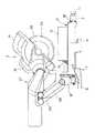
【図1】本発明の実施形態の卓上切断機の正面図。
【図2】本発明の卓上切断機のベース及びターンテーブルを示す平面図。
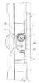
【図3】丸鋸本体を取り付けた状態における図2のIII−III線断面図。
【図4】図2のIV−IV線断面図。
【図5】図2のV−V線断面図。
【図6】本発明の卓上切断機のベース及びターンテーブルを示す部分拡大断面図。
【図7】本発明の卓上切断機のターンテーブルの底面図。
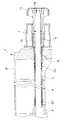
【図8】本発明の卓上切断機の右側面図。
【図9】本発明の卓上切断機のベベルロック機構を示す説明図。
【図10】図3のX−X線端面図。
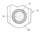
【図11】図3のXI−XI線端面図。
【図12】図2のXII−XII線断面図。
【図13】図12におけるマイターロックシャフト及びベベルロックシャフトの取付け構造を示す拡大部分断面図。
【図14】マイターロック操作ハンドル及びベベルロック操作ハンドルの取付け構造を示す断面図。
【図15】マイターロックシャフトとベベルロックシャフトとの間隔を保持するための保持手段の変形例を示す断面図。
【図16】図15の部分拡大断面図。
【符号の説明】
1:ベース
2:ターンテーブル
3:丸鋸本体
4:マイターロック機構
5:マイターロックシャフト
7:マイターロック操作ハンドル
8:ベベルロック機構
9:ベベルロックシャフト
11:ベベルロック操作ハンドル
16:傾動停止機構
18:傾動停止操作ハンドル[0001]
BACKGROUND OF THE INVENTION
The present invention includes a base and a circular saw body that is movable between a cutting standby position and a cutting completion position along the plane of the saw blade and tiltable along a plane orthogonal to the plane of the saw blade. And a bevel lock mechanism for fixing and releasing the tilt of the circular saw body, a miter lock mechanism for fixing and releasing the turntable to the base, and the circular saw body when tilting from one to the other In particular, the present invention relates to a tabletop cutting machine provided with at least one of tilt stop mechanisms for stopping tilting of a circular saw body when the saw blade is positioned vertically.
[0002]
[Prior art]
With respect to an example of a tabletop cutting machine that has been widely used in the past, the base can be moved between a cutting standby position and a cutting completion position along the plane of the saw blade, and along a plane orthogonal to the plane of the saw blade. A tabletop cutting machine having a circular saw body attached to a base so as to be tiltable and a bevel lock mechanism for fixing and releasing the tilt of the circular saw body is known.
[0003]
As another example of the tabletop cutting machine, the base, the turntable rotatably attached to the base, the cutting standby position and the cutting completion position can be moved along the plane of the saw blade, and the saw can be moved. A circular saw body attached to the turntable so as to be tiltable along a plane perpendicular to the plane of the blade, a miter lock mechanism for fixing and releasing the turntable to the base, and fixing the tilting of the circular saw body; A tabletop cutting machine having a bevel lock mechanism for releasing is known.
[0004]
With respect to still another example of the tabletop cutting machine, the base can be moved between the cutting standby position and the cutting completion position along the plane of the saw blade, and can be tilted along a plane perpendicular to the plane of the saw blade. The mounted circular saw body, the bevel lock mechanism for fixing and releasing the tilt of the circular saw body, and when the saw blade is positioned vertically when the circular saw body tilts from one to the other, A tabletop cutting machine having a tilt stop mechanism for stopping the tilt of the saw body is known.
[0005]
In such a tabletop cutting machine, the tilting of the circular saw body is fixed and released by operating a bevel lock operation handle. When the circular saw body tilts from one side to the other, if the saw blade is positioned vertically, the tilt stop mechanism stops the tilting of the circular saw body, and the saw blade is held in a vertical state. When the circular saw body is further tilted from this state to the other side, the tilt stop of the circular saw body by the tilt stop mechanism is released by operating the tilt stop operation handle.
[0006]
[Problems to be solved by the invention]
However, in the above-described conventional tabletop cutting machine, the bevel lock operation handle for the bevel lock mechanism and the tilt stop operation handle for the tilt stop mechanism are arranged on the rear side of the base. They had to move to the rear of the machine and manipulate these handles, which was very cumbersome.
[0007]
In addition, the operator can extend his / her hand to the rear side of the base and operate these handles in a state where the operator is positioned on the front side of the tabletop cutting machine. It is difficult to visually confirm the position, and therefore, the operation must be performed after confirming the position of the handle by groping, resulting in a problem that the operability is significantly lowered. Furthermore, in order to perform such an operation, there is a risk of injury when the hand is extended to the rear side of the base and the hand is caught on a member near the saw blade, and in particular, there is a safety cover around the saw blade. If it is not provided, the hand may directly contact the saw blade, which may cause serious injury.
[0008]
Accordingly, an object of the present invention is to provide a tabletop cutting machine capable of operating a bevel lock mechanism and / or a tilt stop mechanism very easily, safely and reliably.
[0009]
[Means for Solving the Problems]
The present invention of
The bevel lock mechanism (8) includes a bevel lock operation handle (11) disposed on the front side of the base (1), extends from the front side of the base (1) to the rear side, and extends to the base (1). A bevel lock shaft (9) movable by the bevel lock operation handle (11) so as to press the bracket (10).It is characterized by that.
[0010]
According to a second aspect of the present invention, there is provided a base (1), a turntable (2) rotatably attached to the base (1), and a plane of a saw blade (25) between a cutting standby position and a cutting completion position. Can be moved along, andUsing a bracket (10) rotatable relative to the turntable (2)Inclinable along a plane perpendicular to the plane of the saw blade (25)Behind the turntable (2)The mounted circular saw body (3), the miter lock mechanism (4) for fixing and releasing the turntable (2) to the base (1), and the tilting of the circular saw body (3) In a tabletop cutting machine equipped with a bevel lock mechanism (8) for fixing and releasing,
A miter lock operation handle (7) for the miter lock mechanism (4) is disposed on the front side of the turntable (2).,
The bevel lock mechanism (8) includes a bevel lock operation handle (11) disposed on the front side of the turntable (2), and extends from the front side of the turntable (2) to the rear side and the turntable (2). And 2) a bevel lock shaft (9) movable by the bevel lock operation handle (11) so as to press the bracket (10).It is characterized by that.
[0011]
According to a third aspect of the present invention, there is provided the tabletop cutting machine according to the second aspect, wherein a miter lock shaft (5) for the miter lock mechanism (4) and a bevel lock shaft (9) for the bevel lock mechanism (8) are provided. Are arranged on the same axis at intervals via the holding means (2c, 23, 24) so that they do not contact each other,
The miter lock operation handle (7) is attached to one end of the miter lock shaft (5), and the bevel lock operation handle (11) is attached to one end of the bevel lock shaft (9).
It is characterized by that.
[0012]
The present invention of
The tilt stop mechanism (16) includes a tilt stop operation handle (18) disposed on the front side of the base (1), and extends from the front side of the base (1) to the rear side and the tilt stop operation handle ( A tilt stop shaft (17) rotatable by 18) and a lock pin (20) rotatable by the tilt stop shaft (17) so that the rotating bracket (10) hits.It is characterized by that.
[0013]
According to a fifth aspect of the present invention, there is provided a base (1), a turntable (2) rotatably attached to the base (1), and a plane of a saw blade (25) between a cutting standby position and a cutting completion position. Can be moved along, andUsing a bracket (10) rotatable relative to the turntable (2)The turntable (2) is tiltable along a plane perpendicular to the plane of the saw blade (25).Rear side ofA circular saw body (3) attached to the base, a miter lock mechanism (4) for fixing and releasing the turntable (2) to and from the base (1), and tilting of the circular saw body (3) When the saw blade (25) is positioned vertically when the bevel lock mechanism (8) for fixing and releasing the ring and the circular saw body (3) tilt from one to the other, the circular saw In the tabletop cutting machine provided with the tilt stop mechanism (16) for stopping the tilt of the main body (3),
A miter lock operation handle (7) for the miter lock mechanism (4) is disposed on the front side of the turntable (2), and a bevel lock operation handle (11) for the bevel lock mechanism (8). Is located on the front side of the turntable (2),
The tilt stop mechanism (16) includes a tilt stop operation handle (18) disposed on the front side of the turntable (2), and extends from the front side to the rear side of the turntable (2) and the tilt stop operation. A tilt stop shaft (17) rotatable by a handle (18) and a lock pin (20) rotatable by the tilt stop shaft (17) so that the rotating bracket (10) hits.It is characterized by that.
[0014]
Hereinafter, the present invention will be described with reference to the drawings illustrating embodiments of the present invention. However, the present invention is not limited to the illustrated form.
[0015]
DETAILED DESCRIPTION OF THE INVENTION
Hereinafter, an embodiment of the present invention will be described with reference to FIGS.
[0016]
The tabletop cutting machine according to the embodiment of the present invention includes a
[0017]
As shown in FIG. 2, the
[0018]
As shown in FIG. 2, the
[0019]
In the
[0020]
On the other hand, in the
[0021]
The
[0022]
In this manner, the
[0023]
As described above, the circular saw body 3 is attached to the
[0024]
By adopting the combination of the
[0025]
Accordingly, (1) the
[0026]
A
[0027]
The
[0028]
That is, the plunger bore 40 is provided through the
[0029]
The
[0030]
The
[0031]
The
[0032]
The plurality of
[0033]
In the plurality of
[0034]
According to the
[0035]
As is apparent from FIGS. 4, 6 and 7, the
[0036]
The
[0037]
As is clear from FIG. 6, the
[0038]
As shown in FIG. 14, the miter lock operation handle 7 is formed in a hollow shape, and is attached to the rear end of the above-described
[0039]
Accordingly, if the miter lock operation handle 7 is rotated and the screwing
[0040]
As is clear from FIGS. 4 and 7, the
[0041]
As shown in FIG. 4, the
[0042]
On the other hand, a bevel lock operation handle 11 is fixed to the rear end of the
[0043]
Accordingly, when the bevel lock operation handle 11 is rotated in one direction, the overhanging
[0044]
As described above, the
[0045]
As can be seen from FIGS. 5, 7, and 9, the
[0046]
The
[0047]
The rotation limit position in one direction of the
[0048]
The
[0049]
The stopper means 22 includes a bolt 22a and a
[0050]
The tilt stop operation handle 18 is attached to the rear end of the
[0051]
Therefore, when the circular saw body 3 tilts from one side to the other, when the
[0052]
In the tabletop cutting machine of the present invention, the
[0053]
Next, the operation method of the above-described tabletop cutting machine of the present invention will be described below.
[0054]
A first cutting pattern in which the material to be cut 31 made of cuboid wood is cut in a state where the rotation angle of the
[0055]
First, in a state where the inclination angle of the
[0056]
Next, the miter lock operation handle 7 arranged on the front side of the
[0057]
Next, with the circular saw body 3 held in the uppermost position, that is, the cutting standby position as shown in FIG. 1, the circular saw body 3 is moved to the front side of the
[0058]
In the state described above, the circular saw body 3 is moved downward while being pressed downward (see FIG. 3). As a result, the material to be cut 31 is cut straight in a direction perpendicular to the outer side surface. In other words, the material to be cut 31 has an upper side (hereinafter referred to as “reference line”) on the outer side surface in the plane. And the outer side surface is cut to have a cutting surface defined by a cutting line perpendicular to the reference line.
[0059]
Next, in a state where the rotation angle of the
[0060]
Of course, also in the second cutting pattern, as in the first cutting pattern described above, the circular saw body 3 is linked to the
[0061]
First, the miter lock operation handle 7 arranged on the front side of the
[0062]
Next, as in the first cutting pattern, the circular saw body 3 is held at the uppermost position, that is, the cutting standby position as shown in FIG. 1, the motor (not shown) is driven to rotate the
[0063]
In the state described above, the circular saw body 3 is moved downward while being pressed downward (see FIG. 3). As a result, the material to be cut 31 has a cutting surface defined by a cutting line oblique to the reference line on the plane and a cutting line perpendicular to the reference line on the outer side surface of the material to be cut 31. Cut to have.
[0064]
Further, the material to be cut 31 made of rectangular parallelepiped wood is cut in a state where the rotation angle of the
[0065]
Of course, also in the third cutting pattern, as in the first cutting pattern described above, the miter lock disposed on the front side of the
[0066]
First, the bevel lock operation handle 11 arranged on the front side of the
[0067]
Of course, the circular saw body 3 can be freely tilted until the
[0068]
Next, as in the first cutting pattern, the circular saw body 3 is held at the uppermost position, that is, the cutting standby position as shown in FIG. 1, the motor (not shown) is driven to rotate the
[0069]
In the state described above, the circular saw body 3 is moved downward while being pressed downward (see FIG. 3). Thereby, the material to be cut 31 has a cutting surface defined by a cutting line perpendicular to the reference line on the plane and a cutting line oblique to the reference line on the outer side surface of the material to be cut 31. Cut to have.
[0070]
Further, the rotation angle of the
[0071]
First, as in the second cutting pattern, the miter lock operation handle 7 is loosened to release the fixation of the
[0072]
Next, as in the third cutting pattern, the bevel lock operation handle 11 is loosened, the circular saw body 3 is tilted so that the inclination angle of the
[0073]
Next, as in the first cutting pattern, the circular saw body 3 is held at the uppermost position, that is, the cutting standby position as shown in FIG. 1, the motor (not shown) is driven to rotate the
[0074]
In the state described above, the circular saw body 3 is moved downward while being pressed downward (see FIG. 3). As a result, the material to be cut 31 has a cutting surface defined by a cutting line oblique to the reference line on the plane and a cutting line oblique to the reference line on the outer side surface of the material to be cut 31. Cut to have.
[0075]
In the tabletop cutting machine according to the above-described embodiment of the present invention, the
[0076]
The tabletop cutting machine according to the above-described embodiment of the present invention includes a
(1) First modification: In the tabletop cutting machine according to the above-described embodiment of the present invention, the
[0077]
{Circle around (2)} Second Modification: In the tabletop cutting machine according to the above-described embodiment of the present invention, the
[0078]
(3) Third modification: In the first modification, the
[0079]
(4) Fourth modification: The tabletop cutting machine is movable between the
[0080]
(5) Fifth modification: In the fourth modification, a
[0081]
In the tabletop cutting machine according to the above-described embodiment of the present invention, the circular saw body 3 has been described as being configured to be movable within a predetermined stroke range permitted by the
[0082]
【The invention's effect】
According to the present invention described in detail above, as described in
[0083]
According to a second aspect of the present invention, the base, the turntable rotatably attached to the base, the cutting standby position and the cutting completion position can be moved along the plane of the saw blade, andUsing a bracket that can rotate with respect to the turntableIt can be tilted along a plane perpendicular to the plane of the saw blade.On the rear side of the turntableA tabletop equipped with an attached circular saw body, a miter lock mechanism for fixing and releasing the turntable to the base, and a bevel lock mechanism for fixing and releasing the tilting of the circular saw body In the cutting machine, a miter lock operation handle for the miter lock mechanism is arranged on the front side of the turntable.The bevel lock mechanism includes a bevel lock operation handle disposed on the front side of the turntable, and the bevel lock operation handle extending from the front side to the rear side of the turntable and pressing the bracket against the turntable. Because it includes a bevel lock shaft that can be moved byThe miter lock mechanism can be operated not only on the front side of the base, but the operator does not have to move to the rear side of the tabletop cutting machine to operate the bevel lock mechanism, and cuts himself on the tabletop. The bevel lock mechanism can be operated very easily, safely and reliably on the front side of the base without extending the hand to the rear side of the base while being positioned on the front side of the machine. Both operations of the bevel lock mechanism can be performed efficiently.
[0084]
According to a third aspect of the present invention, in the tabletop cutting machine of the second aspect, the miter lock shaft for the miter lock mechanism and the bevel lock shaft for the bevel lock mechanism are mutually connected. The miter lock operation handle is attached to one end of the miter lock shaft, and the bevel lock is attached to one end of the bevel lock shaft. Since the operation handle is attached, it is possible to effectively use the installation space between the miter lock shaft and the bevel lock shaft, and the interference between the miter lock shaft and the bevel lock shaft is prevented. Smooth and reliable operation of both bevel lock mechanisms It can be.
[0085]
Furthermore, as described in
[0086]
Furthermore, as described in
[Brief description of the drawings]
FIG. 1 is a front view of a tabletop cutting machine according to an embodiment of the present invention.
FIG. 2 is a plan view showing a base and a turntable of the tabletop cutting machine according to the present invention.
3 is a cross-sectional view taken along the line III-III in FIG. 2 in a state where a circular saw body is attached.
4 is a sectional view taken along line IV-IV in FIG.
5 is a sectional view taken along line VV in FIG.
FIG. 6 is a partially enlarged sectional view showing a base and a turntable of the tabletop cutting machine according to the present invention.
FIG. 7 is a bottom view of the turntable of the tabletop cutting machine of the present invention.
FIG. 8 is a right side view of the tabletop cutting machine of the present invention.
FIG. 9 is an explanatory view showing a bevel lock mechanism of the tabletop cutting machine according to the present invention.
10 is an end view taken along line XX of FIG.
11 is an end view taken along line XI-XI in FIG. 3;
12 is a cross-sectional view taken along line XII-XII in FIG.
13 is an enlarged partial sectional view showing a mounting structure of the miter lock shaft and the bevel lock shaft in FIG.
FIG. 14 is a cross-sectional view showing a mounting structure of a miter lock operation handle and a bevel lock operation handle.
FIG. 15 is a cross-sectional view showing a modified example of the holding means for holding the distance between the miter lock shaft and the bevel lock shaft.
16 is a partially enlarged sectional view of FIG.
[Explanation of symbols]
1: Base
2: Turntable
3: Circular saw body
4: Miter lock mechanism
5: Miter lock shaft
7: Miter lock operation handle
8: Bevel lock mechanism
9: Bevel lock shaft
11: Bevel lock operation handle
16: Tilt stop mechanism
18: Tilt stop operation handle
Claims (5)
Translated fromJapanese前記ベベルロック機構は、
前記ベースの前面側に配置されたベベルロック操作ハンドルと、
前記ベースの前面側から後方側へ延びると共に前記ベースに前記ブラケットを押し付けるように前記ベベルロック操作ハンドルによって移動可能なベベルロックシャフトとを含む
ことを特徴とする卓上切断機。Tilt along a plane perpendicular to the plane of the saw bladeby using a bracket that is movable along the plane of the saw blade between the base and the cutting standby position and the cutting completion position. In a tabletop cutting machine comprising a circular saw body attached tothe rear side of the base as possible, and a bevel lock mechanism for fixing and releasing tilting of the circular saw body,
The bevel lock mechanism is
A bevel lock operation handle disposed on the front side of the base;
A tabletop cutting machinecomprising: a bevel lock shaft that extends from the front side to the rear side of the base and is movable by the bevel lock operation handle so as to press the bracket against the base .
前記マイターロック機構のためのマイターロック操作ハンドルが前記ターンテーブルの前面側に配置されており、
前記ベベルロック機構は、
前記ターンテーブルの前面側に配置されたベベルロック操作ハンドルと、
前記ターンテーブルの前面側から後方側へ延びると共に前記ターンテーブルに前記ブラケットを押し付けるように前記ベベルロック操作ハンドルによって移動可能なベベルロックシャフトとを含む
ことを特徴とする卓上切断機。A base, a turntable rotatably attached to the base, anda bracket that is movable along a plane of a saw blade between a cutting standby position and a cutting completion position androtatable with respect to the turntable miter locking mechanism for a circular saw body that is attachedto the rear side of the tiltable saidturntable along a plane perpendicular to the plane of the saw bladeusing the fixing and release of the said base of the turntable And a tabletop cutting machine comprising a bevel lock mechanism for fixing and releasing the tilt of the circular saw body,
A miter lock operation handle for the miter lock mechanism is disposed on the front side of the turntable,
The bevel lock mechanism is
A bevel lock operation handle disposed on the front side of the turntable;
A tabletop cutting machinecomprising: a bevel lock shaft extending from the front side of the turntable to the rear side and movable by the bevel lock operation handle so as to press the bracket against the turntable .
前記マイターロックシャフトの一端に前記マイターロック操作ハンドルが取り付けられ、前記ベベルロックシャフトの一端に前記ベベルロック操作ハンドルが取り付けられていることを特徴とする請求項2に記載した卓上切断機。The miter lock shaft for the miter lock mechanism and the bevel lock shaft for the bevel lock mechanism are arranged on the same axial center with a spacing therebetween so that they do not contact each other. Has been
The tabletop cutting machine according to claim 2, wherein the miter lock operation handle is attached to one end of the miter lock shaft, and the bevel lock operation handle is attached to one end of the bevel lock shaft.
前記傾動停止機構は、
前記ベースの前面側に配置された傾動停止操作ハンドルと、
前記ベースの前面側から後方側へ延びると共に前記傾動停止操作ハンドルによって回転可能な傾動停止シャフトと、
回転する前記ブラケットが当たるように前記傾動停止シャフトによって回転可能なロックピンとを含む
ことを特徴とする卓上切断機。Tilt along a plane perpendicular to the plane of the saw bladeby using a bracket that is movable along the plane of the saw blade between the base and the cutting standby position and the cutting completion position. A circular saw body attached tothe rear side of the base as possible, a bevel lock mechanism for fixing and releasing tilting of the circular saw body, and when the circular saw body tilts from one to the other, In a tabletop cutting machine provided with a tilt stop mechanism for stopping tilting of the circular saw body when the saw blade is positioned vertically,
The tilt stop mechanism is
A tilt stop operation handle disposed on the front side of the base;
A tilt stop shaft extending from the front side of the base to the rear side and rotatable by the tilt stop operation handle;
A tabletop cutting machinecomprising: a lock pin rotatable by the tilt stop shaft so that the rotating bracket hits .
前記マイターロック機構のためのマイターロック操作ハンドルが前記ターンテーブルの前面側に配置されており、前記ベベルロック機構のためのベベルロック操作ハンドルが前記ターンテーブルの前面側に配置されており、
前記傾動停止機構は、
前記ターンテーブルの前面側に配置された傾動停止操作ハンドルと、
前記ターンテーブルの前面側から後方側へ延びると共に前記傾動停止操作ハンドルによって回転可能な傾動停止シャフトと、
回転する前記ブラケットが当たるように前記傾動停止シャフトによって回転可能なロックピンとを含む
ことを特徴とする卓上切断機。A base, a turntable rotatably attached to the base, anda bracket that is movable along a plane of a saw blade between a cutting standby position and a cutting completion position androtatable with respect to the turntable miter locking mechanism for a circular saw body that is attached to therear side of the tiltable said turntable along a plane perpendicular to the plane of the saw bladeusing the fixing and release of the said base of the turntable A bevel lock mechanism for fixing and releasing tilting of the circular saw body, and when the saw blade is positioned vertically when the circular saw body tilts from one to the other, the circular saw body In a tabletop cutting machine equipped with a tilt stop mechanism for stopping the tilt of
A miter lock operation handle for the miter lock mechanism is arranged on the front side of the turntable, a bevel lock operation handle for the bevel lock mechanism is arranged on the front side of the turntable,
The tilt stop mechanism is
A tilt stop operation handle disposed on the front side of the turntable;
A tilt stop shaft extending from the front side of the turntable to the rear side and rotatable by the tilt stop operation handle;
A tabletop cutting machinecomprising: a lock pin rotatable by the tilt stop shaft so that the rotating bracket hits .
Priority Applications (2)
| Application Number | Priority Date | Filing Date | Title |
|---|---|---|---|
| JP20804897AJP3922476B2 (en) | 1997-08-01 | 1997-08-01 | Tabletop cutting machine |
| US09/515,903US6532853B1 (en) | 1997-08-01 | 2000-02-29 | Table-top cutting machine |
Applications Claiming Priority (2)
| Application Number | Priority Date | Filing Date | Title |
|---|---|---|---|
| JP20804897AJP3922476B2 (en) | 1997-08-01 | 1997-08-01 | Tabletop cutting machine |
| US09/515,903US6532853B1 (en) | 1997-08-01 | 2000-02-29 | Table-top cutting machine |
Publications (2)
| Publication Number | Publication Date |
|---|---|
| JPH1148029A JPH1148029A (en) | 1999-02-23 |
| JP3922476B2true JP3922476B2 (en) | 2007-05-30 |
Family
ID=26516609
Family Applications (1)
| Application Number | Title | Priority Date | Filing Date |
|---|---|---|---|
| JP20804897AExpired - Fee RelatedJP3922476B2 (en) | 1997-08-01 | 1997-08-01 | Tabletop cutting machine |
Country Status (2)
| Country | Link |
|---|---|
| US (1) | US6532853B1 (en) |
| JP (1) | JP3922476B2 (en) |
Cited By (1)
| Publication number | Priority date | Publication date | Assignee | Title |
|---|---|---|---|---|
| DE202015000495U1 (en) | 2014-02-13 | 2015-02-06 | Makita Corporation | Table cutting machine |
Families Citing this family (44)
| Publication number | Priority date | Publication date | Assignee | Title |
|---|---|---|---|---|
| US7252027B2 (en) | 2001-02-08 | 2007-08-07 | Black & Decker Inc. | Miter saw |
| EP1902802B1 (en)* | 2001-02-08 | 2014-04-09 | Black & Decker, Inc. | Miter saw |
| US6658977B2 (en)* | 2001-08-02 | 2003-12-09 | Lee-Cheng Chang | Locking mechanism for inclination adjustment of a blade of a cutting device |
| US7127977B2 (en)* | 2002-02-11 | 2006-10-31 | Porter-Cable/Delta | Remotely actuated beveling systems for a miter saw |
| US6865976B2 (en)* | 2002-09-11 | 2005-03-15 | Black & Decker Inc. | Bevel stop mechanism for a miter saw |
| US7201090B2 (en)* | 2002-10-16 | 2007-04-10 | Robert Bosch Gmbh | Front-accessible bevel locking system |
| USD481401S1 (en) | 2002-11-05 | 2003-10-28 | Emerson Electric Co. | Compound miter saw |
| US20040112190A1 (en)* | 2002-11-26 | 2004-06-17 | Hollis Michael Chad | Bevel angle locking actuator and bevel angle locking system for a saw |
| US6892618B2 (en)* | 2003-08-06 | 2005-05-17 | Chang Chin-Chin | Circular sawing machine having a link mechanism |
| US7059228B2 (en)* | 2003-09-11 | 2006-06-13 | Chin-Chin Chang | Hand-controlled circular saw |
| GB2411620A (en) | 2004-03-02 | 2005-09-07 | Black & Decker Inc | Mitre Saw |
| JP4534549B2 (en)* | 2004-03-26 | 2010-09-01 | 日立工機株式会社 | Tabletop cutting machine |
| US20050247178A1 (en)* | 2004-04-15 | 2005-11-10 | Hetcher Jason D | Power tool having an elastomeric material |
| EP1738850A1 (en)* | 2005-06-28 | 2007-01-03 | Positec Power Tools (Suzhou) Co., Ltd. | Bench-top power tool |
| US8857303B2 (en) | 2005-11-22 | 2014-10-14 | Robert Bosch Gmbh | Locking mechanism for miter saw with hinge linkage linear guide |
| US8499672B2 (en)* | 2005-11-22 | 2013-08-06 | Robert Bosch Gmbh | Power miter saw with hinge linkage linear guides |
| US8631734B2 (en) | 2005-11-22 | 2014-01-21 | Robert Bosch Gmbh | Glide movement controller and power miter saw including such controller |
| US8752461B2 (en) | 2005-11-22 | 2014-06-17 | Robert Bosch Gmbh | Hinge connections and power miter saw with hinge linkage linear guide including such hinge connections |
| JP5051610B2 (en)* | 2006-11-16 | 2012-10-17 | 日立工機株式会社 | Tabletop cutting machine |
| JP5000470B2 (en)* | 2007-12-06 | 2012-08-15 | 株式会社マキタ | Rotation angle display device for rotary table in tabletop cutting machine |
| WO2009072410A1 (en)* | 2007-12-06 | 2009-06-11 | Makita Corporation | Table-top cutter |
| US8359959B2 (en)* | 2008-01-08 | 2013-01-29 | Makita Corporation | Cutting devices |
| JP5064274B2 (en)* | 2008-03-21 | 2012-10-31 | 株式会社マキタ | Tabletop cutting machine |
| JP5154274B2 (en)* | 2008-03-21 | 2013-02-27 | 株式会社マキタ | Tabletop cutting machine |
| JP5231112B2 (en)* | 2008-07-14 | 2013-07-10 | 株式会社マキタ | Tabletop cutting machine |
| US20100058909A1 (en)* | 2008-09-11 | 2010-03-11 | Shaodong Chen | Power tool |
| JP5484714B2 (en)* | 2008-11-20 | 2014-05-07 | 株式会社マキタ | Gear chamber seal structure |
| JP5391840B2 (en)* | 2009-05-29 | 2014-01-15 | 日立工機株式会社 | Tabletop cutting machine |
| CN201760668U (en)* | 2010-06-28 | 2011-03-16 | 南京德朔实业有限公司 | Miter saw |
| CN102615344B (en)* | 2011-01-30 | 2014-04-16 | 苏州宝时得电动工具有限公司 | Cutting machine |
| CN102950331B (en)* | 2011-08-18 | 2014-11-26 | 苏州宝时得电动工具有限公司 | Cutting machine |
| US9339877B2 (en)* | 2012-07-04 | 2016-05-17 | Sumec Hardware & Tools Co., Ltd. | Electric mitre saw |
| CN208195813U (en) | 2015-02-25 | 2018-12-07 | 米沃奇电动工具公司 | Mitre saw |
| EP3283250B1 (en)* | 2015-04-17 | 2022-06-08 | Robert Bosch GmbH | Motorized saw assembly and method of operating |
| JP6830797B2 (en)* | 2016-11-11 | 2021-02-17 | 株式会社マキタ | Desktop cutting machine |
| JP7419112B2 (en)* | 2019-08-23 | 2024-01-22 | 株式会社マキタ | tabletop cutting machine |
| US11383311B2 (en)* | 2019-08-23 | 2022-07-12 | Makita Corporation | Compound miter saw |
| CN110666240B (en)* | 2019-09-29 | 2024-04-12 | 苏州金赛工具有限公司 | Metal cutting machine |
| US12186817B2 (en) | 2020-12-02 | 2025-01-07 | Makita Corporation | Sliding cutting machine |
| JP2023102452A (en) | 2022-01-12 | 2023-07-25 | 株式会社マキタ | Cutting machine on bench |
| DE102022129082A1 (en)* | 2022-11-03 | 2024-05-08 | MAFELL Aktiengesellschaft | Electric processing machine |
| CN117123858A (en)* | 2022-11-08 | 2023-11-28 | 江苏羿昇智能装备有限公司 | Multifunctional numerical control cutting machine clamp holder |
| KR102727252B1 (en)* | 2022-11-15 | 2024-11-07 | 주식회사 케이프렌즈 | Board cutting device for furniture making |
| TWI852535B (en)* | 2023-05-05 | 2024-08-11 | 力山工業股份有限公司 | Saw with a control handle having three-stage adjustment function |
Family Cites Families (6)
| Publication number | Priority date | Publication date | Assignee | Title |
|---|---|---|---|---|
| US5437214A (en)* | 1992-05-22 | 1995-08-01 | Makita Corporation | Miter saw |
| GB9218299D0 (en)* | 1992-08-28 | 1992-10-14 | Black & Decker Inc | A releasable locking device |
| US5497816A (en)* | 1994-09-09 | 1996-03-12 | Darland; Richard E. | Power miter table saw |
| GB2304075B (en)* | 1995-08-10 | 1999-10-20 | Milwaukee Electric Tool Corp | Indexing override mechanism for a slide compound miter saw |
| US5870938A (en)* | 1995-12-12 | 1999-02-16 | Black & Decker Inc. | Bevel locking system for a sliding compound miter saw |
| JP3283745B2 (en)* | 1996-02-05 | 2002-05-20 | 株式会社マキタ | Power tool operating lever |
- 1997
- 1997-08-01JPJP20804897Apatent/JP3922476B2/ennot_activeExpired - Fee Related
- 2000
- 2000-02-29USUS09/515,903patent/US6532853B1/ennot_activeExpired - Fee Related
Cited By (1)
| Publication number | Priority date | Publication date | Assignee | Title |
|---|---|---|---|---|
| DE202015000495U1 (en) | 2014-02-13 | 2015-02-06 | Makita Corporation | Table cutting machine |
Also Published As
| Publication number | Publication date |
|---|---|
| US6532853B1 (en) | 2003-03-18 |
| JPH1148029A (en) | 1999-02-23 |
Similar Documents
| Publication | Publication Date | Title |
|---|---|---|
| JP3922476B2 (en) | Tabletop cutting machine | |
| EP0585841B1 (en) | Miter saw | |
| EP1410886B1 (en) | Bevel angle detent system for a compound miter saw | |
| JP3925046B2 (en) | Tabletop circular saw | |
| US8375836B2 (en) | Cutting devices | |
| JP4780524B2 (en) | Portable cutting machine | |
| US20080047406A1 (en) | Bevel Angle Locking Actuator and Bevel Angle Locking System for a Saw | |
| JPH0999401A (en) | Rake stopper for circular saw | |
| JPH11198101A (en) | Sliding circular saw | |
| US8424433B2 (en) | Support leg devices and cutting tools having the support leg devices | |
| JP2007223133A5 (en) | ||
| JP2006068903A (en) | Tabletop cutting machine | |
| US5595124A (en) | Restraining mechanism | |
| US3242953A (en) | Shoe plate alining means for portable power-driven saw | |
| JP2006044044A (en) | Oblique positioning mechanism of cutter | |
| JP2009066718A (en) | Rotary table positioning device for table-top circular sawing machine | |
| JP4138234B2 (en) | Circular saw table lock device | |
| JP7103002B2 (en) | Cutting machine | |
| JP4528757B2 (en) | Portable electric cutting machine | |
| JP4446285B2 (en) | Portable cutting machine | |
| JPH09277118A (en) | Cutting machine | |
| JP3724172B2 (en) | Tabletop cutting machine | |
| JP3345236B2 (en) | Stopper device for cutting machine | |
| JP6457672B1 (en) | Roofing cutting machine | |
| JP3674291B2 (en) | Tabletop cutting machine |
Legal Events
| Date | Code | Title | Description |
|---|---|---|---|
| A621 | Written request for application examination | Free format text:JAPANESE INTERMEDIATE CODE: A621 Effective date:20040412 | |
| A977 | Report on retrieval | Free format text:JAPANESE INTERMEDIATE CODE: A971007 Effective date:20061106 | |
| A131 | Notification of reasons for refusal | Free format text:JAPANESE INTERMEDIATE CODE: A131 Effective date:20061121 | |
| A521 | Request for written amendment filed | Free format text:JAPANESE INTERMEDIATE CODE: A523 Effective date:20070116 | |
| TRDD | Decision of grant or rejection written | ||
| A01 | Written decision to grant a patent or to grant a registration (utility model) | Free format text:JAPANESE INTERMEDIATE CODE: A01 Effective date:20070206 | |
| A61 | First payment of annual fees (during grant procedure) | Free format text:JAPANESE INTERMEDIATE CODE: A61 Effective date:20070215 | |
| R150 | Certificate of patent or registration of utility model | Free format text:JAPANESE INTERMEDIATE CODE: R150 | |
| LAPS | Cancellation because of no payment of annual fees |