JP3922204B2 - Portable transmitter - Google Patents
Portable transmitterDownload PDFInfo
- Publication number
- JP3922204B2 JP3922204B2JP2003106703AJP2003106703AJP3922204B2JP 3922204 B2JP3922204 B2JP 3922204B2JP 2003106703 AJP2003106703 AJP 2003106703AJP 2003106703 AJP2003106703 AJP 2003106703AJP 3922204 B2JP3922204 B2JP 3922204B2
- Authority
- JP
- Japan
- Prior art keywords
- case
- opening
- film member
- portable transmitter
- push
- Prior art date
- Legal status (The legal status is an assumption and is not a legal conclusion. Google has not performed a legal analysis and makes no representation as to the accuracy of the status listed.)
- Expired - Fee Related
Links
- 239000011347resinSubstances0.000claimsdescription21
- 229920005989resinPolymers0.000claimsdescription21
- 238000007639printingMethods0.000claimsdescription20
- 230000005540biological transmissionEffects0.000claimsdescription2
- 238000007789sealingMethods0.000claims4
- 239000007858starting materialSubstances0.000description8
- 238000005452bendingMethods0.000description5
- 238000004519manufacturing processMethods0.000description5
- XLYOFNOQVPJJNP-UHFFFAOYSA-NwaterSubstancesOXLYOFNOQVPJJNP-UHFFFAOYSA-N0.000description4
- 238000003860storageMethods0.000description3
- 238000000605extractionMethods0.000description2
- 230000002349favourable effectEffects0.000description2
- 238000000465mouldingMethods0.000description2
- 238000005192partitionMethods0.000description2
- 229920003207poly(ethylene-2,6-naphthalate)Polymers0.000description2
- 239000004417polycarbonateSubstances0.000description2
- 239000011112polyethylene naphthalateSubstances0.000description2
- -1polyethylene terephthalatePolymers0.000description2
- 229920000139polyethylene terephthalatePolymers0.000description2
- 239000005020polyethylene terephthalateSubstances0.000description2
- 239000004800polyvinyl chlorideSubstances0.000description2
- 229920000915polyvinyl chloridePolymers0.000description2
- 238000003825pressingMethods0.000description2
- 238000013459approachMethods0.000description1
- 230000000694effectsEffects0.000description1
- 230000005674electromagnetic inductionEffects0.000description1
- 230000001771impaired effectEffects0.000description1
- 238000003780insertionMethods0.000description1
- 230000037431insertionEffects0.000description1
- 239000000463materialSubstances0.000description1
- 238000000034methodMethods0.000description1
- 229920000515polycarbonatePolymers0.000description1
- 238000007650screen-printingMethods0.000description1
- 230000011218segmentationEffects0.000description1
Images


Classifications
- H—ELECTRICITY
- H01—ELECTRIC ELEMENTS
- H01H—ELECTRIC SWITCHES; RELAYS; SELECTORS; EMERGENCY PROTECTIVE DEVICES
- H01H9/00—Details of switching devices, not covered by groups H01H1/00 - H01H7/00
- H01H9/02—Bases, casings, or covers
- H01H9/0214—Hand-held casings
- H01H9/0235—Hand-held casings specially adapted for remote control, e.g. of audio or video apparatus
- G—PHYSICS
- G05—CONTROLLING; REGULATING
- G05G—CONTROL DEVICES OR SYSTEMS INSOFAR AS CHARACTERISED BY MECHANICAL FEATURES ONLY
- G05G1/00—Controlling members, e.g. knobs or handles; Assemblies or arrangements thereof; Indicating position of controlling members
- G05G1/02—Controlling members for hand actuation by linear movement, e.g. push buttons
- G—PHYSICS
- G07—CHECKING-DEVICES
- G07C—TIME OR ATTENDANCE REGISTERS; REGISTERING OR INDICATING THE WORKING OF MACHINES; GENERATING RANDOM NUMBERS; VOTING OR LOTTERY APPARATUS; ARRANGEMENTS, SYSTEMS OR APPARATUS FOR CHECKING NOT PROVIDED FOR ELSEWHERE
- G07C9/00—Individual registration on entry or exit
- G07C9/00174—Electronically operated locks; Circuits therefor; Nonmechanical keys therefor, e.g. passive or active electrical keys or other data carriers without mechanical keys
- G07C9/00944—Details of construction or manufacture
- H—ELECTRICITY
- H01—ELECTRIC ELEMENTS
- H01H—ELECTRIC SWITCHES; RELAYS; SELECTORS; EMERGENCY PROTECTIVE DEVICES
- H01H9/00—Details of switching devices, not covered by groups H01H1/00 - H01H7/00
- H01H9/02—Bases, casings, or covers
- H01H9/0214—Hand-held casings
- H01H9/0235—Hand-held casings specially adapted for remote control, e.g. of audio or video apparatus
- H01H2009/0257—Multisided remote control, comprising control or display elements on at least two sides, e.g. front and back surface
- H—ELECTRICITY
- H01—ELECTRIC ELEMENTS
- H01H—ELECTRIC SWITCHES; RELAYS; SELECTORS; EMERGENCY PROTECTIVE DEVICES
- H01H2223/00—Casings
- H01H2223/002—Casings sealed
- H01H2223/003—Membrane embracing all keys
- H—ELECTRICITY
- H01—ELECTRIC ELEMENTS
- H01H—ELECTRIC SWITCHES; RELAYS; SELECTORS; EMERGENCY PROTECTIVE DEVICES
- H01H2227/00—Dimensions; Characteristics
- H01H2227/032—Operating force
- H—ELECTRICITY
- H01—ELECTRIC ELEMENTS
- H01H—ELECTRIC SWITCHES; RELAYS; SELECTORS; EMERGENCY PROTECTIVE DEVICES
- H01H2231/00—Applications
- H01H2231/032—Remote control
Landscapes
- Engineering & Computer Science (AREA)
- Multimedia (AREA)
- Lock And Its Accessories (AREA)
- Transmitters (AREA)
- Input From Keyboards Or The Like (AREA)
- Manufacture Of Switches (AREA)
- Selective Calling Equipment (AREA)
Description
Translated fromJapanese【0001】
【発明の属する技術分野】
本発明は、携帯型送信機に関するものであり、例えば、車両ドアロックの施錠、解除を行うキーレスエントリーシステムのIDコード送信機や、車両を走行可能状態にするキーレススタータシステムのIDコード送信機に用いて好適なものである。
【0002】
【従来の技術】
従来、この種の携帯型送信機に関し、押動式スイッチを樹脂製ケースに内蔵して構成されたものがある(例えば特許文献1)。
【0003】
図11は、本発明者らの試作検討による特許文献1に類似の携帯型送信機を示す分解斜視図であり、表側分割ケース110と裏側分割ケース120とを嵌合して構成されたケース内に、押動式スイッチ32が実装されたプリント基板31、押動式スイッチ32を押し動操作する操作ノブ170等が収納されている。表側分割ケース110には開口部110fが形成されており、操作ノブ170は開口部110fに組み付けられている。
【0004】
操作ノブ170には、押動式スイッチ32の機能を表示する機能表示部170dを形成する必要があるが、機能表示部170dを印刷で形成すると、操作時の摩擦により印刷剥がれが生じてしまい、意匠性が損なわれてしまう。そこで、図11に示す操作ノブ170では、樹脂による2色成形により機能表示部170dを操作ノブに一体に形成して、上記印刷剥がれ回避を図っている。
【0005】
【特許文献1】
特開2001−140513号公報
【0006】
【発明が解決しようとする課題】
しかし、上述のようにケース110とは別体の操作ノブ170を開口部110fに配置した構造では、操作ノブ170とケース110とのクリアランスが必要となるため、操作ノブ170が開口部110fの片側に寄ってしまい、見栄えが損なわれてしまう可能性がある。
【0007】
また、操作ノブ170の機能表示部170dを2色成形で形成して印刷剥がれ回避を図ると、機能表示部170dの表示内容を変更させたい場合に、新規に金型を製作する必要が生じてしまい、コストアップを招いてしまう。
【0008】
ここで、携帯型送信機をポケット等に入れて携帯している場合等、ユーザーの意図に反して操作ノブ170が操作されてしまうことの防止を図るために、操作ノブ170を操作する際のユーザーの操作力を適度に重くさせたい場合がある。しかしながら、図11に示す構造では、押動式スイッチ32自体が有する操作力でユーザー操作力が決まってしまうため、ユーザー操作力を適度に重くさせることが困難となる。
【0009】
本発明は、上記点に鑑み、携帯型送信機の見栄えを良好にするとともに、機能表示部の表示内容変更にともなうコストアップを抑制し、かつ、ユーザー操作力の調節を容易にできるようにすることを目的とする。
【0010】
【課題を解決するための手段】
上記目的を達成するため、請求項1乃至10に記載の発明では、押動式スイッチ(32)を内蔵する樹脂製のケース(10)と、ケース(10)のうち押動式スイッチ(32)に対向する部分に形成された開口部(11f)と、開口部(11f)を覆うように配置され、ケース(10)と一体に形成された樹脂製のフィルム部材(17)とを備え、フィルム部材(17)は、透光性シート(17a)の裏面に機能表示部(17b、17c、17d)を印刷して構成されていることを特徴とする。
【0011】
これにより、フィルム部材(17)のうち開口部(11f)に対応する部分を押せば、フィルム部材(17)が撓むとともに押動式スイッチ(32)が押し動かされることとなる。すなわち、従来の操作ノブ170の機能をフィルム部材(17)に発揮させることができる。そして、フィルム部材(17)は開口部(11f)を覆うように配置されているので、従来の操作ノブ170とケース110とのクリアランスを廃止することができ、携帯型送信機の見栄えを良好にできる。
【0012】
また、フィルム部材(17)は、透光性シート(17a)の裏面に機能表示部(17b、17c、17d)を印刷して構成されているので、機能表示部(17b、17c、17d)の印刷剥がれを回避できるとともに、印刷内容を変えるだけで表示内容を変更できる。よって、表示内容変更にともなうコストアップを抑制できる。
【0013】
また、ユーザー操作力は、押動式スイッチ(32)自体が有する操作力に加え、フィルム部材(17)の撓みによって生じる弾性力により決定される。そして、上記弾性力は、開口部(11f)の大きさを小さくするほど大きくなる。よって、開口部(11f)の大きさを調節するだけでユーザー操作力の大きさを容易に調節できる。
【0014】
請求項1に記載の発明では、フィルム部材(17)のうち開口部(11f)に対向する部分の他がケース(10)にインモールドされて一体化されており、その一体化された部分が開口部(11f)を囲うように環状に延びて、開口部(11f)の周囲がフィルム部材(17)によりシールされる構成となっていることを特徴とする。
【0015】
これにより、開口部(11f)はフィルム部材(17)により密閉されることとなるので、開口部(11f)からケース(10)内部に水が浸入してしまうことを防止する防水機能を、フィルム部材(17)に付加させることができる。
【0016】
請求項9に記載の発明では、フィルム部材(17)の裏面側に光源(35)を設け、フィルム部材(17)のうち光源(35)と対応する部分に、光源(35)からの光を表面側に透過する透光部(17e)を形成したことを特徴とする。
【0017】
ここで、図11に示す携帯型送信機では、発光して表示させる発光表示部をケースに設けようとすると、光源からの光をケースの表面側へ透過する透光窓をケースに形成する必要が生じる。よって、発光表示部の位置や大きさを変更させたい場合には、ケースの金型を新規に製作する必要が生じてしまい、コストアップを招いてしまう。
【0018】
これに対し、請求項9に記載の発明によれば、透光部(17e)の印刷位置を変えるだけで、発光して表示させる部分の位置や大きさを変更できるので、前記変更にともなうコストアップを抑制できる。
【0019】
請求項2、3、7に記載の発明では、押動式スイッチ(32)とフィルム部材(17)との間に押子部材(11g、18c)を配置したことを特徴とするので、押動式スイッチ(32)とフィルム部材(17)とのギャップを押子部材(11g、18c)で調節することができる。
【0020】
特に、請求項10に記載の発明のように、開口部(11f)は複数形成されており、複数の開口部(11f)は1枚のフィルム部材(17)で覆われている場合において、複数の押動式スイッチ(32)を同一面状に並べて配置し、かつ、フィルム部材(17)を湾曲した状態で配置されている場合には、各々の押動式スイッチ(32)とフィルム部材(17)とのギャップが異なる大きさになるので、押子部材(11g、18c)により各々のギャップを調節するようにして好適である。
【0021】
請求項2、8に記載の発明では、押子部材(11g)を、ケース(10)と樹脂により一体に形成したことを特徴とする。
【0022】
これにより、透光性シート(17a)の裏面に印刷された機能表示部(17b、17c、17d)は、押子部材(11g)と密着して保護されるので、機能表示部(17b、17c、17d)が押動式スイッチ(32)と摺動して剥がれてしまうことを防止できる。しかも、ケース(10)およびフィルム部材(17)と一体に押子部材(11g)を形成するので、部品点数削減を図ることができる。
【0023】
請求項3に記載の発明では、ケース(10)は、開口部(11f)が形成された表側分割ケース(11)と裏側分割ケース(12)とを嵌合して構成され、両分割ケース(11、12)の間には、当該両分割ケース(11、12)間をシールするゴム製のシール部材(18b)が配置され、押子部材(18c)を、シール部材(18b)とゴムにより一体に形成したことを特徴とする。
【0024】
これにより、透光性シート(17a)の裏面に印刷された機能表示部(17b、17c、17d)は、ゴム製の押子部材(18c)により保護されるので、機能表示部(17b、17c、17d)が押動式スイッチ(32)と摺動して剥がれてしまうことを防止できる。しかも、シール部材(18b)と一体に押子部材(18c)を形成するので、部品点数削減を図ることができる。
【0025】
請求項4に記載の発明では、開口部(11f)の全体をフィルム部材(17)の裏面側から覆うゴム製の防水カバー(18a)を備え、防水カバー(18a)を、シール部材(18b)とゴムにより一体に形成したことを特徴とする。
【0026】
請求項5に記載の発明では、ケース(10)は、開口部(11f)が形成された表側分割ケース(11)と裏側分割ケース(12)とを嵌合して構成されており、両分割ケース(11、12)の間に配置され、当該両分割ケース(11、12)間をシールするゴム製のシール部材(18b)と、開口部(11f)の全体をフィルム部材(17)の裏面側から覆うゴム製の防水カバー(18a)とを備え、防水カバー(18a)を、シール部材(18b)とゴムにより一体に形成したことを特徴とする。
【0027】
これにより、フィルム部材(17)とケース(10)との間からケース(10)内に水が浸入してしまっても、押動式スイッチ(32)その他の電子部品を防水カバー(18a)で防水できる。
【0028】
請求項10に記載の発明では、押動式スイッチ(32)および開口部(11f)は複数形成されており、複数の開口部(11f)は1枚のフィルム部材(17)で覆われていることを特徴とする。
【0029】
なお、上記各手段の括弧内の符号は、後述する実施形態に記載の具体的手段との対応関係を示す一例である。
【0030】
【発明の実施の形態】
以下、本発明の各実施形態を図に基づいて説明する。
【0031】
(第1実施形態)
本実施形態は、車両に搭載された所定機器の作動許可条件としてのIDコードを送信する車両用の携帯型送信機に、本発明の携帯型送信機を適用したものである。より具体的には、本実施形態の送信機は、車両ドアロックの施錠、解除を行うキーレスエントリーシステムのIDコード送信機、および車両を走行可能状態にするキーレススタータシステムのIDコード送信機として機能するものである。
【0032】
因みに、キーレスエントリーシステムとは、周知の如く、携帯型送信機から送信されたIDコードが車載受信機にて受信されると、ドアロックの施錠、解除を行うアクチュエータを作動させるシステムである。これにより、車両ユーザーは、メカニカルキーを用いることなく遠隔でドアロックを制御可能にするものである。
【0033】
キーレススタータシステムとは、周知の如く、携帯型送信機から送信されたIDコードが車載受信機にて受信されると、イグニッションスイッチをオンさせて、車両走行用エンジンを自動的に始動させるシステムである。これにより、車両ユーザーは、メカニカルキーを用いることなくエンジン始動を制御可能にするものである。なお、エンジン駆動の車両以外にも、電動モータ駆動の車両にもキーレススタータシステムを適用できることは勿論である。
【0034】
また、これらのシステムの採用にともなって、メカニカルキーを挿入するキー挿入穴を車両に設けることを廃止して、車内物品や車両の盗難抑制を図るようにすることもできる。
【0035】
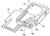
図1ないし図9は本実施形態に係る携帯型送信機を示すものであり、図1は本実施形態に係る携帯型送信機を表面側から見た正面図である。以下、図1の上方を携帯型送信機の上側とし、図1の下方を携帯型送信機の下側として説明する。図2は、携帯型送信機を表面側かつ下側から見た斜視図であり、図3は裏面側かつ上側から見た斜視図である。また、図4は図1のA−A断面図、図5は図1のB−B断面図である。
【0036】
図1ないし図3に示すように、携帯型送信機は樹脂製のケース10を備えており、ケース10には、ボタン電池20、回路基板30、トランスポンダ40、メカニカルキー50等が収容されている。
【0037】
ケース10は、表側分割ケース11と裏側分割ケース12とを取り外し不能に嵌合させて構成されており、嵌合させる事前に、回路基板30およびトランスポンダ40はケース10内に組み付けて収容されるようになっている。これにより、ケース10を破損させることなくトランスポンダ40をケース10内から抜き出すことが極めて困難となるので、ケース10に痕跡を残すことなくトランスポンダ40が抜き取られてしまうことを防止でき、所定機器を不正に作動させることよる各種盗難の危険性を低減できる。
【0038】
取り外し不能な嵌合構造を具体的に説明すると、裏側分割ケース12には、表側分割ケース11に向かって延びる裏側フック12aが複数箇所に形成されている。また、表側分割ケース11には、裏側フック12aの外側に沿って延びる表側フック11aが複数箇所に形成されている。
【0039】
図6は図5の部分拡大図であり、両フック11a、12aのそれぞれには、凸部11b、12bおよび凹部11c、12cが形成されており、表側フック11aの凸部11bは裏側フック12aの凹部12cに嵌合し、裏側フック12aの凸部12bは表側フック11aの凹部11cに嵌合する。
【0040】
両凸部11b、12bのうち嵌合させる際に当接する当接面11d、12dはテーパ形状に形成されており、両凸部11b、12bの凹部11c、12cへの嵌合を案内するようになっている。一方、両凸部11b、12bのうち嵌合後に係合する係合面11e、12eは、嵌合方向に対して略水平に拡がる面に形成されている。これにより、両フック11a、12aのうち少なくとも一方のフックを破損させることなく、両凸部11b、12bを凹部11c、12cから取り外すことを、不能にしている。
【0041】
ボタン電池20は、回路基板30に電源を供給するものである。そして、裏側分割ケース12のうち電池20に対向する部分には、電池取出穴12fが形成されており、当該電池取出穴12fからケース10に対して脱着可能になっている。
【0042】
なお、図4中の符号12gは、電池取出穴12fから穴の内側に向かって延びる抜け止め突出部を示しており、裏側分割ケース12に一体に形成されている。この抜け止め突出部12gは、ボタン電池20に係合してボタン電池20が電池取出穴12fから容易に抜け落ちてしまうことを防止している。
【0043】
また、裏側分割ケース12には、電池取出穴12fを閉塞する樹脂製の蓋13が、図8に示すネジNにより、脱着可能に取り付けられている。裏側分割ケース12と蓋13との間にはシール部材14が配置され、ネジNの締め付けにより圧縮変形して、裏側分割ケースと蓋13との間をシールするようになっている。本実施形態では、ゴム製のOリングをシール部材14に適用させている。
【0044】
また、裏側分割ケース12には、ビスNとともに蓋13を覆うスライドカバー15が取り付けられている。当該スライドカバー15は裏側分割ケース12にスライドして脱着可能となるように取り付けられている。なお、上記スライド方向は、携帯型送信機の上下方向と一致する。
【0045】
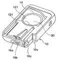
図8はスライドカバー15を裏側分割ケース12から取り外した状態を示す斜視図であり、図9はスライドカバー15および蓋13を裏側分割ケース12から取り外した状態を示す斜視図である。
【0046】
裏側分割ケース12には、スライドカバー15に向けて延びるように形成され、スライドカバー15に係合するカバー用フック16aが備えられており、当該カバー用フック16aは、上記係合によりスライドカバー15の抜け止めとして機能している。
【0047】
また、裏側分割ケース12には、カバー用フック16aの抜け止め機能を解除操作する操作レバー16bが備えられている。操作レバー16bはカバー用フック16aと樹脂にて一体に形成されており、操作レバー16bを操作すると、カバー用フック16aはスライドカバー15から遠離るように動き、上記係合が解除されて、抜け止め機能が解除されることとなり、スライドカバー15がスライド可能となる。
【0048】
メカニカルキー50は、両分割ケース11、12にて形成された収納部10aに収納されており、スライドカバー15を裏側分割ケース12から取り外す向き(携帯型送信機の下側)と、メカニカルキー50を収納部10aから取り外す向きとが同一となるように構成されている。
【0049】
裏側分割ケース12には、メカニカルキー50に向けて延びるように形成され、メカニカルキー50に係合するキー用フック16cが備えられており、当該キー用フック16cは、上記係合によりメカニカルキー50の抜け止めとして機能している。
【0050】
キー用フック16cの抜け止め機能は、上述の操作レバー16bによって、カバー用フック16aの機能解除と連動して解除操作される。具体的には、操作レバー16bを操作すると、キー用フック16cはメカニカルキー50から遠離るように動き、上記係合が解除されて、抜け止め機能が解除されることとなり、メカニカルキー50はケース10から抜き出し可能となる。
【0051】
回路基板30は、プリント配線板31に押動式のタクトスイッチ32、アンテナ33、ターミナル34およびIC等を実装して構成されている。プリント配線板31は、裏側分割ケース12に表側から組み付けられており、タクトスイッチ32はプリント配線板31に対して表側に位置する。なお、タクトスイッチ32は複数備えられており、携帯型送信機の上下方向に並べて配置されている。
【0052】
また、プリント配線板31の裏側には、アンテナ33と、ボタン電池20のプラス極に接触するプラスターミナル34と、マイナス極に接触するマイナスターミナルとが実装されている。
【0053】
トランスポンダ40は、裏側分割ケース12に表側から圧入されて組み付けられている。これにより、トランスポンダ40がケース10に対してガタつくことによる異音発生を防止できる。
【0054】
そして、裏側分割ケース12には、トランスポンダ40とボタン電池20との間を仕切る仕切壁12hが形成されている。これにより、電池取出穴12fからトランスポンダ40が抜き取られてしまうことを確実に防止できる。
【0055】
回路基板30はボタン電池20を電源として作動するようになっており、上述のIDコードを自動的に常時発信するようになっている。また、回路基板30は、ユーザーのスイッチ操作によるタクトスイッチ32の作動にともなって、上述のIDコードを手動で発信するようになっている。
【0056】
図7は図5の部分拡大図であり、表側分割ケース11のうちタクトスイッチ32に対向する部分には開口部11fが形成されている。図1、図2、図4に示すように、当該開口部11fは複数形成されており、携帯型送信機の上下方向に並べて配置されている。
【0057】
開口部11fは、表側分割ケース11と一体に形成された樹脂製のフィルム部材17により覆われている。本実施形態では、複数の開口部11fを1枚のフィルム部材17で覆っている。そして、フィルム部材17のうち開口部11fに対応する部分を押せば、フィルム部材17が撓むとともにタクトスイッチ32が押し動かされることとなる。
【0058】
ここで、ユーザーがフィルム部材17を押す操作力は、タクトスイッチ32自体が有する操作力に加え、フィルム部材17の撓みによって生じる弾性力により決定される。そして、フィルム部材17の撓みによって生じる弾性力は、開口部11fを小さくするほど大きくなる。そこで、開口部11fの大きさは、ユーザー操作力が所望の大きさとなるように設定されている。
【0059】
フィルム部材17は、透光性シート17aの裏面に機能表示部17b、17c、17dを印刷して構成されている。透光性シート17aの材質例としては、PET(ポリエチレンテレフタレート)、PVC(ポリ塩化ビニル)、PEN(ポリエチレンナフタレート)、PC(ポリカーボネート)等が挙げられる。
【0060】
また、透光性シート17aの厚み寸法は、厚すぎると、上記撓みによる弾性力が大きくなりすぎて、開口部11fの大きさによる操作力の調節が困難となってしまう。一方、薄すぎると、フィルム部材17の強度が低くなり、破損が懸念される。これらの点を鑑みて、透光性シート17aの厚み寸法は100μm〜500μmであることが好ましい。
【0061】
機能表示部17b、17c、17dの印刷方法の具体例としては、インキを用いたシルク印刷その他のスクリーン印刷や、トナーを用いた電子写真印刷等が挙げられる。
【0062】
そして、透光性シート17aのうち開口部11fに対応する部分には機能表示部17b、17c、17dが印刷されている。一方、透光性シート17aのうち他の部分においても、機能表示部17b、17c、17dの背景としての印刷が施されており、ケース10内を目隠しするとともに意匠性を良好にすることを図っている。
【0063】
機能表示部17bは、ドアロックを施錠させる機能を表示しており、機能表示部17bに対応するタクトスイッチ32が押動操作されると、ドアロックを施錠させる旨の信号が送信される。機能表示部17cは、ドアロックを解除させる機能を表示しており、機能表示部17cに対応するタクトスイッチ32が押動操作されると、ドアロックを解除させる旨の信号が送信される。機能表示部17dは、トランクルームのドアを開ける機能を表示しており、機能表示部17dに対応するタクトスイッチ32が押動操作されると、トランクルームのドアを開ける旨の信号が送信される。
【0064】
なお、図4では4つのタクトスイッチ32が記載されているが、図1では3つの機能表示部17b、17c、17dに対応する3つのタクトスイッチ32しか使用されていない。これは、4つのタクトスイッチ32を使用する携帯型送信機と本実施形態のように3つのタクトスイッチ32を使用する携帯型送信機との共用化を図るためである。
【0065】
また、フィルム部材17のうち開口部11fに対向する部分の他は、表側分割ケース11にインモールドされて一体化されている。従って、フィルム部材17のうち上記一体化された部分は、開口部11fを囲うように環状に延びることとなり、これにより、開口部11f周囲はフィルム部材17によりシールされる。よって、開口部11fからケース10内への水の浸入を防止することができ、フィルム部材17に防水機能を備えさせることができる。
【0066】
タクトスイッチ32とフィルム部材17との間には、タクトスイッチ32とフィルム部材17とのギャップを調節する押子プレート(押子部材)11gが配置されている。押子プレート11gの板面は、タクトスイッチ32の操作される部位の形状と相似の形状(本実施形態では円形)に形成され、また、タクトスイッチ32の操作される部位よりも僅かに大きい面積となるように形成されている。
【0067】
特に、本実施形態では図4に示すようにフィルム部材17が湾曲した状態で配置しているため、各タクトスイッチ32により上記ギャップの大きさが異なる。よって、上述のように押子プレート11gによってギャップを調節するようにして好適なものである。
【0068】
図7に示すように、表側分割ケース11には、開口部11fから押子プレート11gに向かって延びる接続プレート11hが形成されており、表側分割ケース11、接続プレート11hおよび押子プレート11gは、樹脂により一体に形成されている。
【0069】
ここで、両分割ケース11、12の間には、当該両分割ケース11、12間をシールするゴム製のシール部材18aが配置されている。本実施形態では、ゴム製のOリングをシール部材18aに適用させている。
【0070】
また、回路基板30の表面側全体は防水カバー18bにより覆われており、上記フィルム部材17に加え防水カバー18bによっても回路基板30は防水されるようになってる。そして、上記防水カバー18bはOリング18aとゴムにより一体に形成されている。
【0071】
図1の点線35は、プリント配線板31の表面に実装された光源(例えば発光ダイオード)を示している。そして、透光性シート17aの背景印刷部のうち発光ダイオード35に対応する部分には、透光部17eが形成されており、発光ダイオード35から発光した光は透光部17eを透過して携帯型送信機の所有者に視認される。
【0072】
因みに、本実施形態では、ボタン電池20の電圧が回路基板30を駆動させることができない電圧に近づいた際に、発光ダイオード35の発光を停止させて、ボタン電池20の電圧低下を所有者に報知するようにしている。
【0073】
図1、図2および図4に示すように、表側分割ケース11の表面には、機能表示部17b、17c、17dをブラインド操作可能にするための凹凸部11iが形成されている。具体的には、凹凸部11iは複数の突起状に形成され、表側分割ケース11の下方部位に形成されている。
【0074】
なお、図4に示すように、フィルム部材17のうち機能表示部17b、17c、17dに対応する部分は、表側分割ケース11の表面から僅かに凹むように形成されており、これにより、機能表示部17b、17c、17dのブラインド操作を容易にするとともに、携帯型送信機をポケットに入れて携帯している場合等に、機能表示部17b、17c、17dを誤って押動操作してしまうことの防止を図っている。
【0075】
次に、上記構成による携帯型送信機の作動を説明すると、ボタン電池20の電圧が所定値以上である通常使用時には、キーレスエントリーシステムの車載受信機から所定距離だけ離れた第1エリア内に携帯型送信機が存在すると、回路基板30から自動的に発信されたIDコードが受信機に受信される。そして、キーレスエントリーシステムにて予め設定されているIDコードと受信したIDコードが一致した場合に、ドアロックの施錠、解除を行うアクチュエータが作動する。
【0076】
第1エリアよりも広い第2エリア内においては、回路基板30から自動的に発信されたIDコードは受信されないものの、機能表示部17b、17c、17dを押してタクトスイッチ32を手動操作することにより発信されたIDコードは受信可能となっており、上記アクチュエータが作動可能である。
【0077】
また、キーレススタータシステムの車載受信機は、携帯型送信機を持つ所有者が乗車した場合、回路基板30から自動的に発信されたIDコードが受信機に受信されて、キーレススタータシステムにて予め設定されているIDコードと受信したIDコードが一致した場合に、イグニッションスイッチをオンさせて、エンジンが始動される。
【0078】
以上により、車両ユーザーは、メカニカルキー50を用いることなく遠隔でドアロックを制御できる。また、メカニカルキー50を用いることなくエンジンを始動させることができる。
【0079】
一方、ボタン電池20の電圧が低くなって所定値未満となり、上述した回路基板30によるIDコード送信が不能になった緊急使用時には、操作レバー16bを操作してメカニカルキー20をケース10の収納部10aから取り出し、メカニカルキー20をドアの鍵穴に挿入して回動操作することにより、ドアロックの施錠、解除を行うことが可能である。
【0080】
また、回路基板30によるIDコード送信が不能になった場合にエンジン始動させたい場合には、車室内の運転席近傍に設けられた携帯型送信機収納穴に携帯型送信機を収納する。すると、上記収納穴近傍に備えられた呼掛機は、トランスポンダ40に向けて、IDコードを送信する旨の呼掛信号を自動的に送信する。トランスポンダ40は、車両側から電磁誘導等により電源供給され、上記呼掛信号を受信すると、収納穴近傍に備えられた受信機に向けてIDコードを送信する。そして、予め設定されているIDコードと受信したIDコードが一致した場合には、イグニッションスイッチをオンさせて、エンジンが始動される。
【0081】
なお、上記各々のIDコードはセキュリティ性を保つために暗号化されていることは勿論である。
【0082】
以上により、本実施形態によれば、図11に示す従来の操作ノブ170の機能をフィルム部材17に発揮させることができる。そして、フィルム部材17は開口部11fを覆うように配置されているので、従来の操作ノブ170とケース110とのクリアランスを廃止することができ、携帯型送信機の見栄えを良好にできる。
【0083】
また、従来の操作ノブ170の機能をフィルム部材17に発揮させることができるので、フィルム部材17の厚み方向に携帯型送信機の小型化を図ることができる。
【0084】
また、フィルム部材17は、透光性シート17aの裏面に機能表示部17b、17c、17dを印刷して構成されているので、機能表示部17b、17c、17dの摩擦等による印刷剥がれを回避できるとともに、印刷内容を変えるだけで表示内容を変更できる。よって、表示内容変更にともなうコストアップを抑制できる。
【0085】
また、ユーザー操作力は、タクトスイッチ32自体が有する操作力に加え、フィルム部材17の撓みによって生じる弾性力により決定される。そして、上記弾性力は、開口部11fの大きさを小さくするほど大きくなる。よって、開口部11fの大きさを調節するだけでユーザー操作力の大きさを容易に調節できる。
【0086】
また、タクトスイッチ32とフィルム部材17との間に押子プレート11gを配置しているので、機能表示部17b、17c、17dにタクトスイッチ32が直接当接してしまうことを防止でき、機能表示部17b、17c、17dの印刷剥がれを防止できる。なお、押子プレート11gとフィルム部材17とは一体に形成されているため、押子プレート11gとフィルム部材17とは摺動することがない。よって、押子プレート11gによる印刷剥がれは生じない。
【0087】
(第2実施形態)
上記第1実施形態では、押子プレート11gを表側分割ケース11と樹脂により一体に形成しているが、本実施形態では図10に示すように、押子プレート18cを防水カバー18bとゴムにより一体に形成している。
【0088】
この押子プレート18cによっても第1実施形態の押子プレート11gと同様の効果を得ることができる。なお、押子プレート18cとフィルム部材17とは摺動するものの、押子プレート18cはゴム製であるため、タクトスイッチ32がフィルム部材17に直接当接する場合に比べれば、機能表示部17b、17c、17dの印刷剥がれを抑制できる。
【0089】
(他の実施形態)
本発明の実施にあたり、フィルム部材17のうち表側分割ケース11と一体化された部分を、開口部11fを囲うように環状に延びるように形成すれば、開口部11fからケース10内部に水が浸入してしまうことを防止する防水機能を、フィルム部材17に付加させることができるので、この場合には、上述の防水カバー18aを廃止することができる。
【0090】
また、上記第1および第2実施形態では、第1エリア内に携帯型送信機が存在すると、回路基板30から自動的に発信されたIDコードの受信によりアクチュエータが作動する機能と、第2エリア内にて、機能表示部17b、17c、17dを押してタクトスイッチ32を手動操作することにより発信されたIDコードの受信によりアクチュエータが作動する機能とを備えているが、本発明の実施にあたり、第1エリア内にて自動発信されたIDコードの受信によりアクチュエータが作動する機能を廃止するようにしてもよい。
【0091】
また、上記第1および第2実施形態では、本発明の携帯型送信機を、車両用の、キーレスエントリーシステムおよびキーレススタータシステムに適用させているが、本発明は、上記システムに限られるものではなく、また、車両用に限られるものでもない。例えば、本発明は携帯電話にも適用でき、また、住居の出入口に設けられたドアロックの施錠、解除を行うキーレスエントリーシステムにも適用できる。
【図面の簡単な説明】
【図1】本発明の第1実施形態に係る携帯型送信機を表面側から見た正面図である。
【図2】第1実施形態に係る携帯型送信機を表面側かつ下側から見た斜視図である。
【図3】第1実施形態に係る携帯型送信機を裏面側かつ上側から見た斜視図である。
【図4】図1のA−A断面図である。
【図5】図1のB−B断面図である。
【図6】第1実施形態に係る携帯型送信機の、両分割ケース11、12の嵌合部分を示す図5の拡大図である。
【図7】第1実施形態に係る携帯型送信機の、フィルム部材17、押子プレート11gおよびタクトスイッチ32等を示す図5の部分拡大図である。
【図8】第1実施形態に係る携帯型送信機の、スライドカバー15を裏側分割ケース12から取り外した状態を示す斜視図である。
【図9】第1実施形態に係る携帯型送信機の、スライドカバー15および蓋13を裏側分割ケース12から取り外した状態を示す斜視図である。
【図10】本発明の第2実施形態に係る携帯型送信機を表面側から見た正面図である。
【図11】本発明者らの試作検討による特許文献1に類似の携帯型送信機を示す、分解斜視図である。
【符号の説明】
10…ケース、11f…開口部、17…フィルム部材、
17a…透光性シート、17b、17c、17d…機能表示部、
32…タクトスイッチ(押動式スイッチ)。[0001]
BACKGROUND OF THE INVENTION
The present invention relates to a portable transmitter, for example, an ID code transmitter of a keyless entry system that locks and unlocks a vehicle door lock, and an ID code transmitter of a keyless starter system that enables a vehicle to travel. It is suitable for use.
[0002]
[Prior art]
Conventionally, there is a portable transmitter of this type in which a push switch is built in a resin case (for example, Patent Document 1).
[0003]
FIG. 11 is an exploded perspective view showing a portable transmitter similar to Patent Document 1 as a result of trial production by the present inventors. In the case formed by fitting the front-side divided
[0004]
The
[0005]
[Patent Document 1]
JP 2001-140513 A
[0006]
[Problems to be solved by the invention]
However, in the structure in which the
[0007]
In addition, if the
[0008]
Here, when the portable transmitter is carried in a pocket or the like, when the
[0009]
In view of the above points, the present invention makes it possible to improve the appearance of a portable transmitter, to suppress an increase in cost associated with a change in display content of a function display unit, and to easily adjust a user operation force. For the purpose.
[0010]
[Means for Solving the Problems]
In order to achieve the above object, claim 1 is provided.
[0011]
Thereby, if the part corresponding to an opening part (11f) among film members (17) is pushed, a film member (17) will be bent and a push type switch (32) will be pushed. That is, the function of the
[0012]
Moreover, since the film member (17) is configured by printing the function display portions (17b, 17c, 17d) on the back surface of the translucent sheet (17a), the film member (17) has a function display portion (17b, 17c, 17d). The printing content can be avoided and the display content can be changed simply by changing the printing content. Therefore, an increase in cost due to a change in display content can be suppressed.
[0013]
The user operation force is determined by the elastic force generated by the bending of the film member (17) in addition to the operation force of the push switch (32) itself. And the said elastic force becomes so large that the magnitude | size of an opening part (11f) is made small. Therefore, it is possible to easily adjust the magnitude of the user operation force only by adjusting the size of the opening (11f).
[0014]
Claim1 In the invention described in, out of the film member (17)The other part facing the opening (11f) is in-molded and integrated into the case (10). Integrated partBut It extends in an annular shape so as to surround the opening (11f)The periphery of the opening (11f) is sealed by the film member (17). It is characterized by that.
[0015]
Thereby, since the opening (11f) is sealed by the film member (17), the film has a waterproof function for preventing water from entering the case (10) from the opening (11f). It can be added to the member (17).
[0016]
Claim9 The light source (35) is provided on the back side of the film member (17), and the light from the light source (35) is directed to the surface of the film member (17) corresponding to the light source (35). A translucent portion (17e) that transmits light is formed.
[0017]
Here, in the portable transmitter shown in FIG. 11, when a light emitting display unit for emitting and displaying light is provided in the case, it is necessary to form a light transmitting window in the case for transmitting light from the light source to the surface side of the case. Occurs. Therefore, when it is desired to change the position and size of the light emitting display portion, it becomes necessary to newly manufacture a mold for the case, resulting in an increase in cost.
[0018]
In contrast, the claims9 According to the invention described in (1), since the position and size of the portion to be emitted and displayed can be changed simply by changing the printing position of the translucent portion (17e), an increase in cost due to the change can be suppressed.
[0019]
[0020]
In particular, the
[0021]
Claim2, 8 The invention described in item (1) is characterized in that the presser member (11g) is formed integrally with the case (10) and resin.
[0022]
Thereby, since the function display part (17b, 17c, 17d) printed on the back surface of the translucent sheet (17a) is adhered and protected with the pusher member (11g), the function display part (17b, 17c) is protected. , 17d) can be prevented from sliding off the push-type switch (32) and peeling off. Moreover, since the pusher member (11g) is formed integrally with the case (10) and the film member (17), the number of parts can be reduced.
[0023]
[0024]
Thereby, since the function display part (17b, 17c, 17d) printed on the back surface of the translucent sheet (17a) is protected by the rubber pusher member (18c), the function display part (17b, 17c) is protected. , 17d) can be prevented from sliding off the push-type switch (32) and peeling off. Moreover, since the pusher member (18c) is formed integrally with the seal member (18b), the number of parts can be reduced.
[0025]
Claim4 The rubber cover (18a) made of rubber covers the entire opening (11f) from the back side of the film member (17), and the waterproof cover (18a) is made of the seal member (18b) and rubber. It is formed integrally.
[0026]
Claim5 In the invention described in (1), the case (10) is configured by fitting a front-side divided case (11) having an opening (11f) and a back-side divided case (12). , 12), and covers the entirety of the opening (11f) from the back side of the film member (17) and the rubber seal member (18b) that seals between the divided cases (11, 12). A waterproof cover (18a) made of rubber is provided, and the waterproof cover (18a) is integrally formed of a seal member (18b) and rubber.
[0027]
Thereby, even if water enters the case (10) from between the film member (17) and the case (10), the push-type switch (32) and other electronic components are covered with the waterproof cover (18a). Can be waterproof.
[0028]
Claim 10 In the invention described in (1), a plurality of push-type switches (32) and openings (11f) are formed, and the plurality of openings (11f) are covered with a single film member (17). And
[0029]
In addition, the code | symbol in the bracket | parenthesis of each said means is an example which shows a corresponding relationship with the specific means as described in embodiment mentioned later.
[0030]
DETAILED DESCRIPTION OF THE INVENTION
Hereinafter, embodiments of the present invention will be described with reference to the drawings.
[0031]
(First embodiment)
In this embodiment, the portable transmitter of the present invention is applied to a portable transmitter for a vehicle that transmits an ID code as an operation permission condition for a predetermined device mounted on the vehicle. More specifically, the transmitter of the present embodiment functions as an ID code transmitter of a keyless entry system that locks and unlocks a vehicle door lock, and an ID code transmitter of a keyless starter system that makes the vehicle runnable. To do.
[0032]
Incidentally, as is well known, the keyless entry system is a system that operates an actuator that locks and unlocks a door lock when an in-vehicle receiver receives an ID code transmitted from a portable transmitter. Thus, the vehicle user can control the door lock remotely without using a mechanical key.
[0033]
As is well known, a keyless starter system is a system that automatically turns on an ignition switch and automatically starts a vehicle running engine when an in-vehicle receiver receives an ID code transmitted from a portable transmitter. is there. Thereby, the vehicle user can control the engine start without using the mechanical key. Of course, the keyless starter system can be applied to a vehicle driven by an electric motor in addition to a vehicle driven by an engine.
[0034]
In addition, with the adoption of these systems, it is possible to eliminate the provision of a key insertion hole for inserting a mechanical key in a vehicle and to suppress theft of in-vehicle items and vehicles.
[0035]
1 to 9 show a portable transmitter according to the present embodiment, and FIG. 1 is a front view of the portable transmitter according to the present embodiment as viewed from the front side. In the following description, the upper side of FIG. 1 is the upper side of the portable transmitter, and the lower side of FIG. 1 is the lower side of the portable transmitter. 2 is a perspective view of the portable transmitter as viewed from the front side and from the lower side, and FIG. 3 is a perspective view of the portable transmitter as viewed from the back side and from the upper side. 4 is a cross-sectional view taken along the line AA in FIG. 1, and FIG. 5 is a cross-sectional view taken along the line BB in FIG.
[0036]
As shown in FIGS. 1 to 3, the portable transmitter includes a
[0037]
The
[0038]
Specifically, the non-removable fitting structure will be described. The back
[0039]
FIG. 6 is a partially enlarged view of FIG. 5. The
[0040]
The contact surfaces 11d and 12d that come into contact with each other when the two
[0041]
The
[0042]
In addition, the code |
[0043]
In addition, a
[0044]
Further, a
[0045]
FIG. 8 is a perspective view showing a state in which the
[0046]
The rear divided
[0047]
In addition, the rear divided
[0048]
The
[0049]
The
[0050]
The retaining function of the
[0051]
The
[0052]
On the back side of the printed
[0053]
The
[0054]
A
[0055]
The
[0056]
FIG. 7 is a partially enlarged view of FIG. 5, and an
[0057]
The
[0058]
Here, the operation force with which the user pushes the
[0059]
The
[0060]
On the other hand, if the thickness dimension of the
[0061]
Specific examples of the printing method of the
[0062]
And the
[0063]
The
[0064]
Although four
[0065]
Further, the
[0066]
Between the
[0067]
In particular, in this embodiment, since the
[0068]
As shown in FIG. 7, the front side split
[0069]
Here, a
[0070]
The entire surface of the
[0071]
A dotted
[0072]
Incidentally, in this embodiment, when the voltage of the
[0073]
As shown in FIGS. 1, 2, and 4, an uneven portion 11 i is formed on the surface of the
[0074]
In addition, as shown in FIG. 4, the part corresponding to the
[0075]
Next, the operation of the portable transmitter having the above configuration will be described. During normal use in which the voltage of the
[0076]
In the second area wider than the first area, although the ID code automatically transmitted from the
[0077]
In addition, the in-vehicle receiver of the keyless starter system receives an ID code automatically transmitted from the
[0078]
As described above, the vehicle user can control the door lock remotely without using the
[0079]
On the other hand, during emergency use in which the voltage of the
[0080]
In addition, when it is desired to start the engine when the ID code transmission by the
[0081]
Of course, each ID code is encrypted in order to maintain security.
[0082]
As described above, according to this embodiment, the function of the
[0083]
Further, since the function of the
[0084]
Moreover, since the
[0085]
The user operation force is determined by the elastic force generated by the bending of the
[0086]
Further, since the
[0087]
(Second Embodiment)
In the first embodiment, the
[0088]
The same effect as that of the
[0089]
(Other embodiments)
In carrying out the present invention, if a portion of the
[0090]
In the first and second embodiments, when the portable transmitter is present in the first area, the actuator operates by receiving the ID code automatically transmitted from the
[0091]
In the first and second embodiments, the portable transmitter of the present invention is applied to a keyless entry system and a keyless starter system for a vehicle. However, the present invention is not limited to the above system. Neither is it limited to vehicles. For example, the present invention can be applied to a mobile phone, and can also be applied to a keyless entry system that locks and releases a door lock provided at a doorway of a residence.
[Brief description of the drawings]
FIG. 1 is a front view of a portable transmitter according to a first embodiment of the present invention as viewed from the front side.
FIG. 2 is a perspective view of the portable transmitter according to the first embodiment when viewed from the front side and the lower side.
FIG. 3 is a perspective view of the portable transmitter according to the first embodiment as viewed from the back side and from above.
4 is a cross-sectional view taken along the line AA in FIG.
5 is a cross-sectional view taken along the line BB in FIG.
6 is an enlarged view of FIG. 5 showing a fitting portion of both split
7 is a partially enlarged view of FIG. 5 showing the
FIG. 8 is a perspective view showing a state in which the
9 is a perspective view showing a state in which the
FIG. 10 is a front view of a portable transmitter according to a second embodiment of the present invention as viewed from the front side.
FIG. 11 is an exploded perspective view showing a portable transmitter similar to Japanese Patent Application Laid-Open No. H10-228707, which was examined by trial production by the present inventors.
[Explanation of symbols]
10 ... case, 11f ... opening, 17 ... film member,
17a ... translucent sheet, 17b, 17c, 17d ... function display unit,
32 ... tact switch (push-type switch).
Claims (10)
Translated fromJapanese前記ケース(10)のうち前記押動式スイッチ(32)に対向する部分に形成された開口部(11f)と、
前記開口部(11f)を覆うように配置され、前記ケース(10)と一体に形成された樹脂製のフィルム部材(17)とを備え、
前記フィルム部材(17)は、透光性シート(17a)の裏面に機能表示部(17b、17c、17d)を印刷して構成されており、
前記フィルム部材(17)のうち前記開口部(11f)に対向する部分の他が前記ケース(10)にインモールドされて一体化されており、その一体化された部分が前記開口部(11f)を囲うように環状に延びて、前記開口部(11f)の周囲が前記フィルム部材(17)によりシールされる構成となっていることを特徴とする携帯型送信機。A resin case (10) containing a push-type switch (32);
An opening (11f) formed in a portion of the case (10) facing the push-type switch (32);
A resin film member (17) disposed so as to cover the opening (11f) and integrally formed with the case (10);
The film member (17) is configured by printing function display portions (17b, 17c, 17d) on the back surface of the translucent sheet (17a),
The other part of the film member (17) facing the opening (11f) is in-molded and integrated with the case (10), and the integrated part is the opening (11f). A portable transmitter characterized inthat itextends in an annular shape so as to surround the opening, and the periphery of the opening (11f) is sealed by the film member (17) .
前記ケース(10)のうち前記押動式スイッチ(32)に対向する部分に形成された開口部(11f)と、
前記開口部(11f)を覆うように配置され、前記ケース(10)と一体に形成された樹脂製のフィルム部材(17)とを備え、
前記フィルム部材(17)は、透光性シート(17a)の裏面に機能表示部(17b、17c、17d)を印刷して構成されており、
前記押動式スイッチ(32)と前記フィルム部材(17)との間に押子部材(11g、18c)を配置した携帯型送信機であって、
前記押子部材(11g)を、前記ケース(10)と樹脂により一体に形成したことを特徴とする携帯型送信機。A resin case (10) containing a push-type switch (32);
An opening (11f) formed in a portion of the case (10) facing the push-type switch (32);
A resin film member (17) disposed so as to cover the opening (11f) and integrally formed with the case (10);
The film member (17) is configured by printing function display portions (17b, 17c, 17d) on the back surface of the translucent sheet (17a),
A portable transmitter in which a pusher member (11g, 18c) is disposed between the push-type switch (32) and the film member (17),
It said pusher member (11g) and portable transmitteryou characterized in that it is integrally formed by the casing (10) and the resin.
前記ケース(10)のうち前記押動式スイッチ(32)に対向する部分に形成された開口部(11f)と、
前記開口部(11f)を覆うように配置され、前記ケース(10)と一体に形成された樹脂製のフィルム部材(17)とを備え、
前記フィルム部材(17)は、透光性シート(17a)の裏面に機能表示部(17b、17c、17d)を印刷して構成されており、
前記押動式スイッチ(32)と前記フィルム部材(17)との間に押子部材(11g、18c)を配置した携帯型送信機であって、
前記ケース(10)は、前記開口部(11f)が形成された表側分割ケース(11)と裏側分割ケース(12)とを嵌合して構成され、
前記両分割ケース(11、12)の間には、当該両分割ケース(11、12)間をシールするゴム製のシール部材(18b)が配置され、
前記押子部材(18c)を、前記シール部材(18b)とゴムにより一体に形成したことを特徴とする携帯型送信機。A resin case (10) containing a push-type switch (32);
An opening (11f) formed in a portion of the case (10) facing the push-type switch (32);
A resin film member (17) disposed so as to cover the opening (11f) and integrally formed with the case (10);
The film member (17) is configured by printing function display portions (17b, 17c, 17d) on the back surface of the translucent sheet (17a),
A portable transmitter in which a pusher member (11g, 18c) is disposed between the push-type switch (32) and the film member (17),
The case (10) is configured by fitting a front side split case (11) formed with the opening (11f) and a back side split case (12),
Between the split cases (11, 12), a rubber seal member (18b) for sealing between the split cases (11, 12) is disposed.
Said pusher member (18c) and a portable transmitteryou characterized in that it is formed integrally by said sealing member (18b) and rubber.
前記防水カバー(18a)を、前記シール部材(18b)とゴムにより一体に形成したことを特徴とする請求項3に記載の携帯型送信機。A rubber waterproof cover (18a) covering the entire opening (11f) from the back side of the film member (17);
The portable transmitter according to claim3 , wherein the waterproof cover (18a) is formed integrally with the seal member (18b) by rubber.
前記ケース(10)のうち前記押動式スイッチ(32)に対向する部分に形成された開口部(11f)と、
前記開口部(11f)を覆うように配置され、前記ケース(10)と一体に形成された樹脂製のフィルム部材(17)とを備え、
前記フィルム部材(17)は、透光性シート(17a)の裏面に機能表示部(17b、17c、17d)を印刷して構成されている携帯型送信機であって、
前記ケース(10)は、前記開口部(11f)が形成された表側分割ケース(11)と裏側分割ケース(12)とを嵌合して構成されており、
前記両分割ケース(11、12)の間に配置され、当該両分割ケース(11、12)間をシールするゴム製のシール部材(18b)と、
前記開口部(11f)の全体を前記フィルム部材(17)の裏面側から覆うゴム製の防水カバー(18a)とを備え、
前記防水カバー(18a)を、前記シール部材(18b)とゴムにより一体に形成したことを特徴とする携帯型送信機。A resin case (10) containing a push-type switch (32);
An opening (11f) formed in a portion of the case (10) facing the push-type switch (32);
A resin film member (17) disposed so as to cover the opening (11f) and integrally formed with the case (10);
The film member (17) is a portable transmitter configured by printing a function display unit (17b, 17c, 17d) on the back surface of a translucent sheet (17a),
The case (10) is configured by fitting a front side split case (11) formed with the opening (11f) and a back side split case (12),
A rubber seal member (18b) disposed between the two split cases (11, 12) and sealing between the split cases (11, 12);
A rubber waterproof cover (18a) that covers the entire opening (11f) from the back side of the film member (17);
Wherein the waterproof cover (18a), a portable transmitteryou characterized in that it is formed integrally with the rubber the sealing member (18b).
前記複数の開口部(11f)は1枚の前記フィルム部材(17)で覆われていることを特徴とする請求項1ないし9のいずれか1つに記載の携帯型送信機。A plurality of the push switch (32) and the opening (11f) are formed,
The portable transmitter according to any one of claims 1 to9 , wherein the plurality of openings (11f) are covered with one film member (17).
Priority Applications (2)
| Application Number | Priority Date | Filing Date | Title |
|---|---|---|---|
| JP2003106703AJP3922204B2 (en) | 2003-04-10 | 2003-04-10 | Portable transmitter |
| US10/819,962US7046136B2 (en) | 2003-04-10 | 2004-04-08 | Portable transmitter having tact switches with front film |
Applications Claiming Priority (1)
| Application Number | Priority Date | Filing Date | Title |
|---|---|---|---|
| JP2003106703AJP3922204B2 (en) | 2003-04-10 | 2003-04-10 | Portable transmitter |
Publications (2)
| Publication Number | Publication Date |
|---|---|
| JP2004312621A JP2004312621A (en) | 2004-11-04 |
| JP3922204B2true JP3922204B2 (en) | 2007-05-30 |
Family
ID=33127923
Family Applications (1)
| Application Number | Title | Priority Date | Filing Date |
|---|---|---|---|
| JP2003106703AExpired - Fee RelatedJP3922204B2 (en) | 2003-04-10 | 2003-04-10 | Portable transmitter |
Country Status (2)
| Country | Link |
|---|---|
| US (1) | US7046136B2 (en) |
| JP (1) | JP3922204B2 (en) |
Families Citing this family (35)
| Publication number | Priority date | Publication date | Assignee | Title |
|---|---|---|---|---|
| DE112006000258T5 (en)* | 2005-01-21 | 2007-12-06 | Bloomfield, Richard M., Novi | Remote keyless entry device with integrated access-controllable memory |
| JP4548205B2 (en)* | 2005-04-27 | 2010-09-22 | 株式会社デンソー | Wireless transceiver and manufacturing method thereof |
| JP4144619B2 (en)* | 2005-09-22 | 2008-09-03 | 松下電工株式会社 | Wireless transmitter |
| TWI274360B (en)* | 2005-10-18 | 2007-02-21 | Asustek Comp | Noise reducing key structure |
| US7598462B2 (en)* | 2006-01-11 | 2009-10-06 | Lear Corporation | Sealed remote keyless entry device |
| US7897888B2 (en)* | 2006-03-30 | 2011-03-01 | Strattec Security Corporation | Key fob device and method |
| DE102006026910B4 (en)* | 2006-06-09 | 2020-04-02 | BSH Hausgeräte GmbH | Control unit for a household appliance |
| KR100877049B1 (en) | 2006-09-28 | 2009-01-07 | 가시오 히타치 모바일 커뮤니케이션즈 컴퍼니 리미티드 | Waterproof structure |
| JP4725895B2 (en)* | 2006-09-28 | 2011-07-13 | Necカシオモバイルコミュニケーションズ株式会社 | Waterproof structure of the housing |
| US7564001B2 (en)* | 2006-12-04 | 2009-07-21 | Panasonic Corporation | Switch and remote controller using the same |
| FR2916891B1 (en)* | 2007-05-29 | 2014-02-28 | Valeo Securite Habitacle | DEVICE FOR REMOTELY CONTROLLING A LATCHING / UNLOCKING SYSTEM OF A MOTOR VEHICLE, SUPPORT STRUCTURE FOR SUCH DEVICE AND FUNCTIONAL UNIT COMPRISING THE STRUCTURE. |
| JP2011517143A (en)* | 2008-01-09 | 2011-05-26 | ジョンソン コントロールズ テクノロジー カンパニー | Bi-directional portable electronic device interacting with vehicle system |
| JP5115310B2 (en)* | 2008-04-28 | 2013-01-09 | 富士通株式会社 | Mobile terminal device |
| CN102324332A (en)* | 2008-07-21 | 2012-01-18 | 斯特拉泰克安全公司 | Electronic communication equipment and method |
| JP5107838B2 (en)* | 2008-09-10 | 2012-12-26 | 日本開閉器工業株式会社 | Switch mounting tool |
| JP5287330B2 (en) | 2009-02-19 | 2013-09-11 | 株式会社デンソー | Electronic key |
| JP4947179B2 (en)* | 2010-03-30 | 2012-06-06 | 株式会社デンソー | Portable transmitter |
| FR2960090A1 (en)* | 2010-05-11 | 2011-11-18 | Peugeot Citroen Automobiles Sa | Remote control, has receptacle closed by movable trap unlockable by button, and return units that are constituted by compression spring, where button is fixed on body and placed at junction between body and trap |
| JP5578959B2 (en)* | 2010-06-18 | 2014-08-27 | 東京パーツ工業株式会社 | Push switch |
| DE102010060977B4 (en)* | 2010-12-02 | 2023-05-04 | Witte Automotive Gmbh | Key with colored housing |
| JP5587161B2 (en)* | 2010-12-22 | 2014-09-10 | 東京パーツ工業株式会社 | Push switch and manufacturing method thereof |
| CN103459738B (en)* | 2011-03-30 | 2015-10-14 | 松下电器产业株式会社 | Electron key |
| JP5615774B2 (en)* | 2011-07-13 | 2014-10-29 | 株式会社東海理化電機製作所 | Packing for switch and electronic key using the same |
| DE102011056934A1 (en)* | 2011-12-21 | 2013-06-27 | Huf Hülsbeck & Fürst Gmbh & Co. Kg | Mobile identification transmitter with a flexible film which at least partially comprises the housing |
| JP5423782B2 (en) | 2011-12-27 | 2014-02-19 | 株式会社デンソー | Electronic key for vehicle |
| CN203338261U (en)* | 2013-05-31 | 2013-12-11 | 梁徽湖 | Stylus with waterproof function |
| JP6425002B2 (en)* | 2013-10-30 | 2018-11-21 | 株式会社デンソー | Portable wireless key |
| JP6498385B2 (en)* | 2014-03-31 | 2019-04-10 | 三菱重工機械システム株式会社 | Portable authentication device for mechanical parking facility and control method for portable authentication device for mechanical parking facility |
| FR3024092B1 (en)* | 2014-07-28 | 2018-01-26 | Delta Dore | REMOTE CONTROL |
| WO2016141062A2 (en) | 2015-03-05 | 2016-09-09 | Dolby Laboratories Licensing Corporation | Mechanical structure for button on satellite microphone |
| DE102020106214A1 (en)* | 2019-03-08 | 2020-09-10 | Lixil Corporation | Remote toilet control |
| US12165452B2 (en)* | 2021-08-05 | 2024-12-10 | Panasonic Automotive Systems Co., Ltd. | Electronic key terminal |
| CN115309026A (en)* | 2022-08-08 | 2022-11-08 | 黄超明 | Universal waterproof watch case for wearing products |
| US20250111719A1 (en)* | 2023-10-02 | 2025-04-03 | Fca Us Llc | Electric component retention in remote entry device |
| USD1067201S1 (en)* | 2024-08-26 | 2025-03-18 | Guangzhou Guanmingjie Intelligent Photoelectric Technology Co., Ltd | Remote control key |
Family Cites Families (7)
| Publication number | Priority date | Publication date | Assignee | Title |
|---|---|---|---|---|
| CN1274009C (en)* | 1994-06-15 | 2006-09-06 | 精工爱普生株式会社 | Method for making thin-film semicondcutor device |
| JP3700200B2 (en)* | 1995-06-05 | 2005-09-28 | ソニー株式会社 | Portable telephone equipment |
| JPH10223080A (en) | 1997-02-04 | 1998-08-21 | Tokai Rika Co Ltd | Switch device |
| JP3642506B2 (en) | 1999-02-19 | 2005-04-27 | 信越ポリマー株式会社 | Pushbutton switch structure |
| JP2001140513A (en) | 1999-11-18 | 2001-05-22 | Calsonic Kansei Corp | Portable transmitter |
| JP3505478B2 (en)* | 2000-06-28 | 2004-03-08 | 三洋電機株式会社 | Nitride-based semiconductor laser device and method of manufacturing nitride-based semiconductor laser device |
| US6366538B1 (en)* | 2000-08-29 | 2002-04-02 | Securealert, Inc. | Interference structure for emergency response system wristwatch |
- 2003
- 2003-04-10JPJP2003106703Apatent/JP3922204B2/ennot_activeExpired - Fee Related
- 2004
- 2004-04-08USUS10/819,962patent/US7046136B2/ennot_activeExpired - Lifetime
Also Published As
| Publication number | Publication date |
|---|---|
| US20040200709A1 (en) | 2004-10-14 |
| US7046136B2 (en) | 2006-05-16 |
| JP2004312621A (en) | 2004-11-04 |
Similar Documents
| Publication | Publication Date | Title |
|---|---|---|
| JP3922204B2 (en) | Portable transmitter | |
| JP3835427B2 (en) | Portable transmitter | |
| JP4190934B2 (en) | Portable transmitter | |
| US7652391B2 (en) | Starting button apparatus for vehicle | |
| KR100966498B1 (en) | Switch device | |
| US20130141212A1 (en) | Vehicle access | |
| US9959688B2 (en) | Portable wireless key | |
| JP5974767B2 (en) | Door lock control system | |
| US11613212B2 (en) | Interior rearview mirror assembly with removable portable accessory module | |
| EP1443470B1 (en) | Remote control key for preventing theft of transponder and method for manufacturing the same | |
| EP2495141B1 (en) | Antenna device | |
| JP4821338B2 (en) | Rear opening / closing structure of automobile | |
| WO2015104747A1 (en) | Vehicle electronic key system portable device | |
| JP5043789B2 (en) | Switch device | |
| JP4300633B2 (en) | Electronic key structure | |
| JP2007211475A (en) | Opening/closing structure for automobile | |
| KR19980048092U (en) | Car Door Lock Check Lamp |
Legal Events
| Date | Code | Title | Description |
|---|---|---|---|
| A621 | Written request for application examination | Free format text:JAPANESE INTERMEDIATE CODE: A621 Effective date:20050511 | |
| A131 | Notification of reasons for refusal | Free format text:JAPANESE INTERMEDIATE CODE: A131 Effective date:20061107 | |
| A521 | Request for written amendment filed | Free format text:JAPANESE INTERMEDIATE CODE: A523 Effective date:20061219 | |
| TRDD | Decision of grant or rejection written | ||
| A01 | Written decision to grant a patent or to grant a registration (utility model) | Free format text:JAPANESE INTERMEDIATE CODE: A01 Effective date:20070130 | |
| A61 | First payment of annual fees (during grant procedure) | Free format text:JAPANESE INTERMEDIATE CODE: A61 Effective date:20070212 | |
| R150 | Certificate of patent or registration of utility model | Ref document number:3922204 Country of ref document:JP Free format text:JAPANESE INTERMEDIATE CODE: R150 Free format text:JAPANESE INTERMEDIATE CODE: R150 | |
| FPAY | Renewal fee payment (event date is renewal date of database) | Free format text:PAYMENT UNTIL: 20110302 Year of fee payment:4 | |
| FPAY | Renewal fee payment (event date is renewal date of database) | Free format text:PAYMENT UNTIL: 20120302 Year of fee payment:5 | |
| FPAY | Renewal fee payment (event date is renewal date of database) | Free format text:PAYMENT UNTIL: 20120302 Year of fee payment:5 | |
| FPAY | Renewal fee payment (event date is renewal date of database) | Free format text:PAYMENT UNTIL: 20130302 Year of fee payment:6 | |
| FPAY | Renewal fee payment (event date is renewal date of database) | Free format text:PAYMENT UNTIL: 20140302 Year of fee payment:7 | |
| R250 | Receipt of annual fees | Free format text:JAPANESE INTERMEDIATE CODE: R250 | |
| R250 | Receipt of annual fees | Free format text:JAPANESE INTERMEDIATE CODE: R250 | |
| R250 | Receipt of annual fees | Free format text:JAPANESE INTERMEDIATE CODE: R250 | |
| R250 | Receipt of annual fees | Free format text:JAPANESE INTERMEDIATE CODE: R250 | |
| R250 | Receipt of annual fees | Free format text:JAPANESE INTERMEDIATE CODE: R250 | |
| R250 | Receipt of annual fees | Free format text:JAPANESE INTERMEDIATE CODE: R250 | |
| R250 | Receipt of annual fees | Free format text:JAPANESE INTERMEDIATE CODE: R250 | |
| R250 | Receipt of annual fees | Free format text:JAPANESE INTERMEDIATE CODE: R250 | |
| LAPS | Cancellation because of no payment of annual fees |