JP3922047B2 - Data receiving apparatus, received data processing method, and computer program - Google Patents
Data receiving apparatus, received data processing method, and computer programDownload PDFInfo
- Publication number
- JP3922047B2 JP3922047B2JP2002049181AJP2002049181AJP3922047B2JP 3922047 B2JP3922047 B2JP 3922047B2JP 2002049181 AJP2002049181 AJP 2002049181AJP 2002049181 AJP2002049181 AJP 2002049181AJP 3922047 B2JP3922047 B2JP 3922047B2
- Authority
- JP
- Japan
- Prior art keywords
- data
- packet
- difference
- system clock
- clock
- Prior art date
- Legal status (The legal status is an assumption and is not a legal conclusion. Google has not performed a legal analysis and makes no representation as to the accuracy of the status listed.)
- Expired - Fee Related
Links
- 238000003672processing methodMethods0.000titleclaimsdescription21
- 238000004590computer programMethods0.000titleclaimsdescription10
- 238000012545processingMethods0.000claimsdescription74
- 238000000034methodMethods0.000claimsdescription58
- 230000005540biological transmissionEffects0.000claimsdescription48
- 230000008569processEffects0.000claimsdescription42
- 238000004458analytical methodMethods0.000claimsdescription38
- 238000005259measurementMethods0.000claimsdescription22
- 239000000872bufferSubstances0.000claimsdescription21
- 230000003139buffering effectEffects0.000claimsdescription8
- 238000004364calculation methodMethods0.000claimsdescription4
- 238000010586diagramMethods0.000description18
- 238000004891communicationMethods0.000description16
- 230000001360synchronised effectEffects0.000description10
- 238000012546transferMethods0.000description10
- 238000001514detection methodMethods0.000description7
- 230000006978adaptationEffects0.000description5
- 238000012937correctionMethods0.000description5
- 230000006835compressionEffects0.000description3
- 238000007906compressionMethods0.000description3
- 230000003111delayed effectEffects0.000description3
- 238000013500data storageMethods0.000description2
- 230000000694effectsEffects0.000description2
- 230000006870functionEffects0.000description2
- 238000012544monitoring processMethods0.000description2
- 101000969688Homo sapiens Macrophage-expressed gene 1 proteinProteins0.000description1
- 102100021285Macrophage-expressed gene 1 proteinHuman genes0.000description1
- 238000012790confirmationMethods0.000description1
- 125000004122cyclic groupChemical group0.000description1
- 238000011161developmentMethods0.000description1
- 238000005538encapsulationMethods0.000description1
- 238000005516engineering processMethods0.000description1
- 239000000284extractSubstances0.000description1
- 239000003550markerSubstances0.000description1
- 230000007246mechanismEffects0.000description1
- 238000012986modificationMethods0.000description1
- 230000004048modificationEffects0.000description1
- 238000003752polymerase chain reactionMethods0.000description1
- 230000004044responseEffects0.000description1
- 238000006467substitution reactionMethods0.000description1
Images


Landscapes
- Compression Or Coding Systems Of Tv Signals (AREA)
- Two-Way Televisions, Distribution Of Moving Picture Or The Like (AREA)
- Data Exchanges In Wide-Area Networks (AREA)
- Synchronisation In Digital Transmission Systems (AREA)
Description
Translated fromJapanese【0001】
【発明の属する技術分野】
本発明は、データ受信装置、および受信データ処理方法、並びにコンピュータ・プログラムに関する。さらに詳細には、タイムスタンプに基づく受信パケット処理において、データ送信側と受信側のクロックを同期させた処理を可能とするデータ受信装置、および受信データ処理方法、並びにコンピュータ・プログラムに関する。
【0002】
【従来の技術】
昨今、インターネット通信など、様々な通信媒体を介した画像、音声データ等のデータ転送が盛んに行われている。特に、近年においては、インターネット上のデータ転送において、従来から利用されているダウンロード型伝送方式に加えて、ストリーム型伝送方式によるサービスが増加してきている。ダウンロード型伝送方式においては、映像ファイルや音声ファイルといったマルチメディアデータを伝送する場合、配信サーバからデータファイルを一旦受信側端末の記憶媒体にダウンロードして、その後、記憶媒体から再生することになる。よって、この方式ではファイルを完全に転送が終わるまでは再生できず、長時間再生やリアルタイム再生などには不向きである。
【0003】
一方、後者のストリーム型伝送方式では、送信側から受信端末にデータ転送が行われている間に、並列して受信データの再生処理を実行するものであり、インターネット電話・遠隔テレビ会議・ビデオオンデマンドといったインターネットサービスに利用されている。
【0004】
ストリーム型伝送方式は、例えば画像データのMPEG圧縮処理により生成されるMPEGストリームをIP(Internet Protocol)パケットに格納してインターネット上を転送させて、PCやPDA、携帯電話等の各通信端末において受信するシステム等において使用され、開発が進んでいる。このような技術は、ビデオオンデマンドやライブ映像のストリーミング配信、あるいはビデオ会議、テレビ電話などのリアルタイム通信において有効となる。
【0005】
IPネットワークを用いて、ビデオ会議やビデオオンデマンドなど音声・動画像をストリーミングでリアルタイムに再生して見る場合、一般に、パケットの廃棄やデータエラー時に再送を行うTCP(Transport ControlProtocol)のようなトランスポートプロトコルは、リアルタイム性を保つことが出来ないために使えない。また、TCPは一対一通信用のプロトコルであり、複数の相手に音声・動画像のデータを送信することもできない。そこで一般に、このような用途に対するプロトコミルとしてUDP(User Datagram Protocol)が用いられる。
【0006】
UDPは、アプリケーションのプロセスがリモートマシン上の他のアプリケーションプロセスへデータを転送することを、最小のオーバーヘッドで行えるように設計されている。そのため、UDPのヘッダに入る情報は、送信元ポート番号、宛先ポート番号、データ長、チェックサムのみであり、TCPヘッダには存在するようなパケットの順序を表す番号を入れるフィールドなどがないため、ネットワークでパケットの順序が狂ってしまった場合にその順序を正しく入れ替えるなどの処理が出来ない。また、送信時のタイムスタンプなどの時間情報を入れるフィールドは、TCPにもUDPにも存在しない。
【0007】
TCPヘッダ構成を図1に示す。TCPヘッダには、送信元ポート番号、宛先ポート番号、データパケットの先頭がそのデータの送信初めから何バイトにあたるかをバイト数で示したデータ順序を示すシーケンス番号、相手から次に送られるデータの送信シーケンス番号を示す応答確認番号、ヘッダ長、TCPセグメントの処理方法などのコードビットからなるフラグ情報、データの残り受信可能バイト数を示すウィンドウサイズ、TCPパケットの信頼性保証値としてのチェックサム、緊急処理を要するデータ一を示す緊急ポインタを有する。
【0008】
UDPヘッダの詳細を図2に示す。UDPはコネクションレス型のサービスを提供するプロトコルであり、シンプルなヘッダ構成を持つ。図2に示すようにUDPヘッダには、送信元ポート番号、宛先ポート番号、データ長としてのヘッダとデータ長の総バイト数を示すセグメント長、UDPパケットの信頼性保証値としてのチェックサムを有する。UDPはこのようにシンプルな構成であるため、制御が簡素化される。
【0009】
このようにUDPプロトコルを適用したデータ転送では、ネットワークでパケットの順序が狂ってしまった場合にその順序を正しく入れ替えるなどの処理が出来ない。また、送信時のタイムスタンプなどの時間情報を入れるフィールドは、TCPにもUDPにも存在しない。
【0010】
そこで、RTP(Real−time Transport Protocol)が考え出された。RTPは、インターネット等のIPネットワークにおいて、リアルタイムに音声や動画を送受信するためのトランスポートプロトコルである(RFC1889参照)。一般に、RTPはUDP上で用いられる。RTPはヘッダにシーケンス番号、タイムスタンプなどを入れて送信するため、受信側でパケットの順序訂正ができる、ネットワークでの遅延揺らぎを吸収することができるなど、様々なメリットがあり、例えばVoIP(Voice over IP)の技術などで用いられている。
【0011】
図3にMPEG−2トランスポートストリーム(TS)等のデータをRTP,UDP,IPによりパケット化したIPパケットの構成中のRTPヘッダの詳細を示す。RTPヘッダには、バージョン番号(v)、パディング(P)、拡張ヘッダ(X)の有無、CRSC(Contributing Source)の個数、マーカ情報(M)、ペイロードタイプ、シーケンス番号、RTPタイムスタンプ、同期送信元(SSRC)識別子、および寄与送信元(CSRC)識別子の各フィールドが設けられている。RTPヘッダに付与されたタイムスタンプによりRTPパケットの展開時に処理時間の制御が実行され、リアルタイム画像、または音声の再生制御が可能となる。なお、例えば圧縮データとしてのMPEGトランスポートストリームは、IPパケット中に複数のMPEG−2−TSパケットとして格納される。
【0012】
このようにプロトコル:RTP(Realtime Transport Protocol)は、ストリーム型伝送方式に適したプロトコルであり、IETF RFC1889で規定されている。RTPに従ったデータ転送では、時間情報としてパケットにタイムスタンプを付加し、タイムスタンプの参照により送信側と受信側の時間的関係の把握を行ない、データ受信側において、パケット転送の遅延ゆらぎ(ジッター)などの影響を受けずに同期をとった再生を可能としている。
【0013】
また、画像圧縮符号化の国際標準規格であるMPEG2(Moving Picture Experts Group−2)は放送・通信・蓄積というすべてのアプリケーションに対して汎用的に使用できる動画像圧縮方式で、DVDやデジタルテレビ放送に使われている。
【0014】
MPEG2システムでは、MPEG VideoやMPEG Audioなどの符号化されたビット・ストリーム(ES;Elementary Stream)を複数本統合して、1本のストリームに多重化することが出来る。さらにMPEG2システムでは、図4(a)に示すように、比較的ビットエラー発生の少ない蓄積媒体からの伝送を想定したMPEG2−PS(Program Stream)形式(1本で1つのプログラムを構成する)と、図4(b)に示すように、伝送ビットエラーの発生が予想される通信回線を想定したMPEG2−TS(Transport Stream)形式(1本で複数のプログラムを構成可能)の2種類のフォーマットを規定している。ATMやEthernet等のネットワークでは伝送エラーの発生は避けられないため、そのような用途には一般にMPEG2−TSが用いられる。
【0015】
MPEG2−TSのパケット構成を図5に示す。MPEG2−TSのパケットは、4バイトのヘッダとデータを格納するための184バイトのペイロードから構成される、固定長のパケットである。TSヘッダは1バイトの同期バイト(0x47)と、TSパケットの属性を表すフラグ、13ビットのPID(Packet ID)、スクランブル制御識別子、アダプテーションフィールド識別子、パケットの連続性を検査するのに用いる4ビットの巡回カウンタから構成される。このうち、PIDはそのMPEG2−TSを構成するAudioやVideoのESを区別するために、MPEG2−TSパケットごとに1つずつ付けられる識別子である。
【0016】
また、TSパケットには、図6に示すようにアダプテーションフィールドと呼ばれるフィールドをペイロードのデータフィールド部分全体、もしくはデータの前に入れる形で伝送することができる。このアダプテーションフィールドにはプライベートデータや、PCR(Program Clock Reference)などを格納することが可能である。このPCRは、ベース33bitが90KHzのカウンタ、拡張9bitがそれをさらに1/300にしたカウンタであり、あわせて27MHzを実現するタイムスタンプである。PCRをアダプテーションフィールドにもつTSパケットは、VideoやAudioのストリームとは異なるPIDを持つ。
【0017】
PCRは、MPEG2データの受信側が復号回路のシステムクロックを送信側のそれと同期させるために用いられる。この仕組みを以下に説明する。
【0018】
復号器のクロック周波数が符号器側と完全に一致する場合、映像や音声の復号・表示は送信側に追従し、エンドエンド間の遅延は時間が経過しても一定のままであるが、現実には完全には一致しない。そのため、通信を続けていると送信側に対して受信側の復号・表示がどんどん遅れてくるなどの現象が発生し、特にテレビ電話などのアプリケーションでは致命的である。
【0019】
そのため復号側では、サンプルされた符号器のシステムクロックであるPCRの値をもとに、復号器のシステムタイムクロック(STC:System Time Clock)を符号器のそれに追従させる。この方法としては、例えば図7に示すPLL(Phase Locked Loop)が用いられる。
【0020】
PLLでは、新規のMPEGデータが復号器に到着した場合、STCはPCRの値にセットされる。その後PCRが復号器に到着する度に、引き算器(subtractor)101においてそのPCRの値はカウンタ104の出力する現在のSTC値と比較され、その差分がローパスフィルタおよびゲイン102ステージに渡される。そこからの出力は電圧制御発振器(VCO;Voltage−Controlled Oscillator)103の瞬間値を制御する制御信号である。それによってコントロールされたVCO103からの出力が、新規のシステムクロックとして使用される。
【0021】
このループを繰り返すことにより、最終的には復号器側のシステムクロックは符号器側に一致する。(この状態をロックすると呼ぶ。)なお、MPEG2−TSではこのPLL同期の動作を安定させるために、PCRの送信間隔を100msec以下にすることが決められている。(MPEG2−PSでは700msec)
【0022】
さて、IPネットワークにおいて先に述べたRTPを用いてMPEGを伝送する規格としては「RTP Payload Format for MPEG1/MPEG2 Video」(RFC2250)が標準化提案プロトコルとして存在する。このRFCには、RTPパケットの伝送方法やパケットのカプセル化の方式が記述されており、RTPのペイロード部分に入れるデータとしてMPEG−TSを用いる場合には、1つのRTPパケットにMPEG2−TSのパケットを複数個入れて運ぶことができることになっている。また、RTPのタイムスタンプはPCRと同じ90kHzの周波数による時刻を入れる。つまり図8に示すように、RTPのタイムスタンプはPCRのベースと同期していなければならない。
【0023】
図9(a)に示すように、MPEG2−TSを、ATMなどのネットワークによる遅延揺らぎがほとんどないネットワーク201を用いて伝送する場合には、MPEG2−TSのデータは直接復号器202に入力される。そして、PCRが符号化側のシステムクロックをサンプルして到着するために、PLLを用いて符号側と復号側のシステムクロック203の同期を図ることが出来る。しかし、図9(b)に示すようにインターネット等のIPネットワーク上で伝送する場合のように大きな遅延揺らぎが発生する場合には、ネットワーク211の遅延揺らぎを除去するためにRTPを用いて受信側で遅延揺らぎ吸収バッファ212を用いて一度バッファリングしなければならず、この場合、符号器側のシステムクロックが復号器213側のシステムクロック214に反映されなくなりPLLを用いた方法が使えないという問題が発生する。
【0024】
また、送信データのレートが完全に一定である場合には、図10に示すように、ネットワーク221の遅延揺らぎを除去するために受信側で遅延揺らぎ吸収バッファ222を用いて一度バッファリングした場合でも、データ量監視部225がバッファ内のデータ量を見ながら、送信側のタイミングで復号器223にデータを入力するように制御を実行することで、符号器側のシステムクロックを復号器223側のシステムクロック224に反映させる構成も可能であるが、送信側で動的に符号化レートを変更する場合などには適用できないという問題がある。
【0025】
【発明が解決しようとする課題】
本発明は、上述の問題点に鑑みてなされたものであり、ビデオオンデマンドや、遠隔テレビ会議のような、リアルタイム再生が望まれるデータ通信処理において、RTPを用いてネットワークの遅延揺らぎを除去するために受信側で一度バッファリングする構成とした場合においても、また動的にレートの変更が発生した場合においても、復号器のシステムクロックを符号器側に同期させることを可能としたデータ受信装置、および受信データ処理方法、並びにコンピュータ・プログラムを提供することを目的とする。
【0026】
【課題を解決するための手段】
本発明の第1の側面は、
タイムスタンプの付与されたパケットを受信してパケット格納データの処理を実行するデータ受信装置であり、
予め定められた計測時間間隔前後における受信パケットに付与されたタイムスタンプのタイム差分データ:ΔT_Rと、自装置のシステムクロックの基準クロックタイミングを生成するカウンタ値の差分データ:ΔT_Cとの比較処理を実行する差分解析部と、
前記差分解析部の取得したタイムスタンプのタイム差分データ:ΔT_Rと、カウンタ値の差分データ:ΔT_Cとの、差異に基づいて、前記システムクロックの制御パラメータを生成するクロック制御部と、
前記クロック制御部の制御情報に基づいて生成されるクロックをパケット格納データの処理を実行するパケット処理手段に対して供給するシステムクロックと、
を有することを特徴とするデータ受信装置にある。
【0027】
さらに、本発明のデータ受信装置の一実施態様において、前記パケット処理手段は、前記パケット格納データの復号処理を実行する復号器と、前記パケット格納データのバッファリングを実行するバッファ手段と、を含む構成であることを特徴とする。
【0028】
さらに、本発明のデータ受信装置の一実施態様において、前記クロック制御部は、計測時間間隔:ΔTのときに、前記差分解析部の取得したタイムスタンプのタイム差分データ:ΔT_Rと、カウンタの値の差分データ:ΔT_Cとの差異に基づいて、D=(ΔT_R−ΔT_C)/ΔTによって算出された値:Dを前記システムクロックの制御パラメータとして生成する構成であることを特徴とする。
【0029】
さらに、本発明のデータ受信装置の一実施態様において、前記クロック制御部は、計測時間間隔:ΔTのときに、前記差分解析部の取得したタイムスタンプのタイム差分データ:ΔT_Rと、カウンタの値の差分データ:ΔT_Cとの差異に基づいて、D=(ΔT_R−ΔT_C)/ΔTによって算出された値:Dを前記システムクロックの制御パラメータとして生成し、D>0の場合は、前記カウンタ動作を速め、システムクロックを速める制御情報を前記システムクロックに供給し、D<0の場合は、前記カウンタ動作を遅らせ、システムクロックを遅らせる制御情報を前記システムクロックに供給する処理を実行する構成であることを特徴とする。
【0030】
さらに、本発明のデータ受信装置の一実施態様において、前記タイムスタンプの付与されたパケットはRTPヘッダを有するパケットであり、タイムスタンプは、パケット送信側のクロックに基づいてRTPヘッダ内に格納されるデータであることを特徴とする。
【0031】
さらに、本発明のデータ受信装置の一実施態様において、前記タイムスタンプの付与されたパケットは、MPEG2トランスポートストリームを格納したパケットであり、前記復号器は、MPEG2トランスポートストリームの復号処理を前記システムクロックの供給するクロック信号による制御に基づいて実行する構成であることを特徴とする。
【0032】
さらに、本発明のデータ受信装置の一実施態様において、前記クロック制御部は、予め定められた差分計測時間間隔毎に、タイムスタンプのタイム差分データ:ΔT_Rと、カウンタの値の差分データ:ΔT_Cとの差異に基づくシステムクロックの制御パラメータ算出処理を繰り返し実行する構成であることを特徴とする。
【0033】
さらに、本発明の第2の側面は、
タイムスタンプの付与されたパケットを受信してパケット格納データの処理を実行する受信データ処理方法であり、
予め定められた計測時間間隔前後における受信パケットに付与されたタイムスタンプのタイム差分データ:ΔT_Rと、自装置のシステムクロックの基準クロックタイミングを生成するカウンタの値の前記計測時間間隔前後における差分データ:ΔT_Cとの比較処理を実行する差分解析ステップと、
前記差分解析ステップにおいて取得したタイムスタンプのタイム差分データ:ΔT_Rと、カウンタの値の差分データ:ΔT_Cとの、差異に基づいて、前記システムクロックの制御パラメータを生成する制御パラメータ生成ステップと、制御パラメータ生成ステップにおいて生成する制御情報に基づいて生成されるクロックをパケット格納データの処理を実行するパケット処理手段に対して供給するシステムクロック供給ステップと、
前記クロックに基づくパケットの処理を実行するパケット処理ステップと、
を有することを特徴とする受信データ処理方法にある。
【0034】
さらに、本発明の受信データ処理方法の一実施態様において、前記パケット処理手段は、前記パケット格納データの復号処理を実行する復号器と、前記パケット格納データのバッファリングを実行するバッファ手段とを含み、前記バッファ手段は、前記システムクロック供給ステップにおいて供給されるクロックに基づくパケットの復号器への出力処理を実行し、前記復号器は、前記システムクロック供給ステップにおいて供給されるクロックに基づくパケット格納データの復号処理を実行することを特徴とする。
【0035】
さらに、本発明の受信データ処理方法の一実施態様において、前記制御パラメータ生成ステップは、計測時間間隔:ΔTのときに、前記差分解析部の取得したタイムスタンプのタイム差分データ:ΔT_Rと、カウンタの値の差分データ:ΔT_Cとの差異に基づいて、D=(ΔT_R−ΔT_C)/ΔTによって算出された値:Dを前記システムクロックの制御パラメータとして生成することを特徴とする。
【0036】
さらに、本発明の受信データ処理方法の一実施態様において、前記制御パラメータ生成ステップは、計測時間間隔:ΔTのときに、前記差分解析部の取得したタイムスタンプのタイム差分データ:ΔT_Rと、カウンタの値の差分データ:ΔT_Cとの差異に基づいて、D=(ΔT_R−ΔT_C)/ΔTによって算出された値:Dを前記システムクロックの制御パラメータとして生成し、D>0の場合は、前記カウンタ動作を速め、システムクロックを速める制御情報を前記システムクロックに供給し、D<0の場合は、前記カウンタ動作を遅らせ、システムクロックを遅らせる制御情報を前記システムクロックに供給する処理を実行することを特徴とする。
【0037】
さらに、本発明の受信データ処理方法の一実施態様において、前記タイムスタンプの付与されたパケットは、MPEG2トランスポートストリームを格納したパケットであり、前記復号器は、MPEG2トランスポートストリームの復号処理を前記システムクロックの供給するクロック信号による制御に基づいて実行することを特徴とする。
【0038】
さらに、本発明の受信データ処理方法の一実施態様において、前記制御パラメータ生成ステップは、予め定められた差分計測時間間隔毎に、タイムスタンプのタイム差分データ:ΔT_Rと、カウンタの値の差分データ:ΔT_Cとの差異に基づくシステムクロックの制御パラメータ算出処理を繰り返し実行する構成であることを特徴とする。
【0039】
さらに、本発明の第3の側面は、
タイムスタンプの付与されたパケットを受信してパケット格納データの処理を実行するコンピュータ・プログラムであって、
予め定められた計測時間間隔前後における受信パケットに付与されたタイムスタンプのタイム差分データ:ΔT_Rと、自装置のシステムクロックの基準クロックタイミングを生成するカウンタの値の前記計測時間間隔前後における差分データ:ΔT_Cとの比較処理を実行する差分解析ステップと、
前記差分解析ステップにおいて取得したタイムスタンプのタイム差分データ:ΔT_Rと、カウンタの値の差分データ:ΔT_Cとの、差異に基づいて、前記システムクロックの制御パラメータを生成する制御パラメータ生成ステップと、制御パラメータ生成ステップにおいて生成する制御情報に基づいて生成されるクロックをパケット格納データの処理を実行するパケット処理手段に対して供給するシステムクロック供給ステップと、
前記クロックに基づくパケットの処理を実行するパケット処理ステップと、
を具備することを特徴とするコンピュータ・プログラムにある。
【0040】
なお、本発明のコンピュータ・プログラムは、例えば、様々なプログラム・コードを実行可能な汎用コンピュータ・システムに対して、コンピュータ可読な形式で提供する記憶媒体、通信媒体、例えば、CDやFD、MOなどの記録媒体、あるいは、ネットワークなどの通信媒体によって提供可能なコンピュータ・プログラムである。このようなプログラムをコンピュータ可読な形式で提供することにより、コンピュータ・システム上でプログラムに応じた処理が実現される。
【0041】
本発明のさらに他の目的、特徴や利点は、後述する本発明の実施例や添付する図面に基づくより詳細な説明によって明らかになるであろう。なお、本明細書においてシステムとは、複数の装置の論理的集合構成であり、各構成の装置が同一筐体内にあるものには限らない。
【0042】
【発明の実施の形態】
本発明は、タイムスタンプの付与されたパケット、例えばRTPを用いたデータ通信において、ネットワークの遅延揺らぎを除去するために受信側で一度バッファリングする場合、動的にレートが変更されても、復号器のシステムクロックを符号器側に同期させる構成を持つデータ受信装置、および受信データ処理方法を実現するものである。
【0043】
RTPのヘッダ情報として付加されるタイムスタンプはネットワークの遅延揺らぎが大きい場合でも、平均的には送信側のシステムクロックを表すPCRに同期している。よって、この到着のタイミングをRTPの遅延揺らぎ吸収用バッファの直前で観測することで、送信側のシステムクロックをサンプルすることが出来る。この観測データにより、時間軸上の2点のサンプルをとり、RTPタイムスタンプの増加分と復号側のシステムクロックによるカウンタの増加分を比較して、RTPパケット送信側のシステムクロックとRTPパケット受信側のシステムクロックとのずれを判別するものである。
【0044】
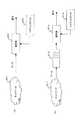
まず、図11を参照して、復号器のシステムクロックを符号器側に同期させる構成を持つデータ受信側装置の構成および処理概要について説明する。
【0045】
例えばMPEG2−TS等のデータをRTPパケットに格納して、インターネット等の遅延揺らぎの発生するネットワーク301を用いて伝送する構成を例とする。
【0046】
データパケットは、図12に示すように、MPEG2−TSを格納し、RTPヘッダ、UDPヘッダ、IPヘッダを持つMPEGoverIPパケットを想定する。RTPヘッダには、データ送信元のシステムクロックに基づいて設定されるタイムスタンプが格納される。
【0047】
図11に戻りデータ受信側装置の構成および処理概要について説明する。ネットワークを介して受信されるMPEG2−TSのデータを格納したIPパケットは、バッファ302に格納されるが、バッファ302に格納される前に、RTPタイムスタンプデータ取得部311が各受信パケットのRTPヘッダからタイムスタンプデータを取得する。
【0048】
RTPタイムスタンプデータ取得部311の取得したタイムスタンプデータは、各パケット受信毎に差分解析部312に入力される。差分解析部312は、RTPタイムスタンプデータ取得部311の取得したタイムスタンプデータを入力するとともに、システムクロック304の基準クロックを生成するカウンタデータを入力する。図13に差分解析部312に入力されるRTPタイムスタンプデータ取得部311の取得したタイムスタンプデータ、およびシステムクロック304のカウンタデータ値の例を示す。各時刻T_0〜nに入力されたタイムスタンプのデータ[RTPT_S0]〜[RTPT_S0]、および対応時刻におけるシステムクロック304のカウンタ値[CNTR_R_0]〜[CNTR_R_n]が順次、差分解析部312内のメモリに格納される。
【0049】
差分解析部312は、ある一定時間間隔、すなわち予め定められた差分検出時間を経過した後、RTPタイムスタンプデータ取得部311の取得した差分検出時間間隔前後の2つのタイムスタンプデータの差分[ΔT_R]と、同一の時間間隔前後におけるシステムクロック304のカウンタの差分[ΔT_C]の各差分データを算出する。
【0050】
差分解析部312の算出したタイムスタンプデータの差分[ΔT_R]と、カウンタの差分[ΔT_C]の各差分データは、クロック制御部313に出力される。
【0051】
クロック制御部313は、差分解析部312の算出したタイムスタンプデータの差分[ΔT_R]と、カウンタの差分[ΔT_C]の各差分データに基づいて、制御パラメータを生成し、生成した制御パラメータに基づいてシステムクロックの基準クロックを生成するカウンタの補正を実行する。
【0052】
制御パラメータ[D]の生成式は、タイムスタンプデータの差分[ΔT_R]と、カウンタの差分[ΔT_C]の各差分データを適用した下式によって求められる。
D=(ΔT_R−ΔT_C)/ΔT……(式1)
【0053】
D=0であれば、タイムスタンプデータの差分[ΔT_R]と、カウンタの差分[ΔT_C]の各差分データは全く等しく、パケット送信側のシステムクロックと、受信側のシステムクロックが同期しており、カウンタの調整は不要となる。D>0であれば、タイムスタンプデータの差分[ΔT_R]が、カウンタの差分[ΔT_C]より大であることを示し、パケット受信側のシステムクロック304のカウンタが、パケット送信側のシステムクロックに比較して遅れがあることを示しており、制御パラメータDの値に対応してシステムクロック304のカウンタを速めるように制御を実行する。
【0054】
D<0であれば、タイムスタンプデータの差分[ΔT_R]が、カウンタの差分[ΔT_C]より小であることを示し、パケット受信側のシステムクロック304のカウンタが、パケット送信側のシステムクロックに比較して速いことを示しており、制御パラメータDの値に対応してシステムクロック304のカウンタを遅くするように制御を実行する。
【0055】
このクロック制御部313における制御によって修正されたカウンタに基づいてシステムクロック304は、復号器303に対するクロック(27MHz)を提供し、またパッファ302に対するクロック(90KHz)を提供する。RTPのタイムスタンプはPCRと同じ90kHzの周波数による時刻を入れてあり、システムクロック304から供給される補正された90KHzクロックにより、各パケットを復号器303に出力し、復号器303において、同様の補正された27MHzクロックでの復号処理を実行することで、符号化器(データ送信側)のシステムクロックとした同期した再生処理が可能となる。
【0056】
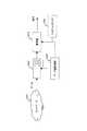
データ送信側である符号化器と、データ受信側である復号器間におけるパケット送受信および、受信側でのカウンタ補正処理について、図14を参照して説明する。
【0057】
図14は、タイムスタンプデータを格納したRTPヘッダを持つパケットを送信する送信側を上段に示し、パケットを受信する受信側を果断に示しており、時間(t)経過を左から右に示したタイムシーケンス図である。
【0058】
データ送信側の装置ではパケットの送信時に、符号器側のシステムクロックに基づいたRTPカウンタの値[R_0]〜[R_N]を各パケットの送信時刻としてのRTPタイムスタンプとして設定しパケットのRTPヘッダ(図12参照)に入れて送信する。
【0059】
受信側に届いたパケットは、復号器側のシステムクロックに基づいたRTPカウンタ[C_0]〜[C_N]に基づいて処理される。つまり、[R_0]〜[R_N]は符号器側クロックを、[C_0]〜[C_N]は復号器側クロックを反映した値になっており、受信側でこれらの値の「単位時間あたりの差分(タイム増加分)」を比較することで、どちらのクロックがどれだけ速いか、あるいは遅いかを判定し、その差分に基づいて、データ受信側(復号側)のクロック調整を実行する。
【0060】
復号側のクロックをデータ送信側(符号化側)に合わせるように調節することで符号器側と復号器側のクロックの同期が実現され、例えば動画像データのリアルタイム再生処理等において、画像データが一時ストップする等の再生乱れの発生が防止される。
【0061】
RTPパケットの通信ネットワーク上での遅延揺らぎがない場合は、図14において(R_1−R_0)=(C_1−C_0)が成り立ち、クロックの調整を行なうことなく受信パケットの良好な再生処理が可能となるが、RTPパケットの通信ネットワーク上での遅延揺らぎがある場合は、受信側でのパケット受信間隔は、送信側でパケットに付与したタイムスタンプの間隔とは異なるものとなる。
【0062】
例えばネットワーク上での遅延が発生すると、単位時間あたりの差分(タイム増加分)、すなわち、(R_1−R_0)と、(C_1−C_0)との差分の誤差が大きくなってしまう。よって、揺らぎの影響を小さくするために、各差分(タイム増加分)の比較は、ある程度の時間間隔、例えばタイムスタンプが(R_0)のパケット到着から、タイムスタンプが(R_N)のパケット到着までの時間間隔を、差分検出時間間隔として設定した上で行う必要がある。
【0063】
図15を参照して、データ受信側(復号器側)の処理を詳細に説明する。先に説明した構成と同様、処理パケットは、先に説明した図12に示すようにMPEG2−TSを格納し、RTPヘッダ、UDPヘッダ、IPヘッダを持つMPEGoverIPパケットを想定する。インターネット等の遅延揺らぎの発生するネットワーク401を用いてタイムスタンプの付加されたRTPヘッダを持つパケットを伝送する構成を例とする。RTPヘッダには、データ送信元のシステムクロックに基づいて設定されるタイムスタンプが格納される。
【0064】
ネットワークを介して受信されるパケットは、バッファ402に格納される前に、RTPタイムスタンプデータ取得部411が各受信パケットのRTPヘッダからタイムスタンプデータを取得する。
【0065】
RTPタイムスタンプデータ取得部411の取得したタイムスタンプデータは、各パケット受信毎に差分解析部412に入力される。差分解析部412は、RTPタイムスタンプデータ取得部411の取得したタイムスタンプデータを入力するとともに、システムクロック404の可変周波数発振器414の基準クロックを生成するカウンタデータを入力する。
【0066】
差分解析部412は、ある程度の時間間隔、例えばタイムスタンプが(R_S)のパケット到着から、タイムスタンプが(R_E)のパケット到着までの時間間隔を、差分検出時間間隔として設定した上で、(R_S−R_E)の差分と、(C_S−C_E)との差分を検出する。
【0067】
図16に差分解析部412に入力されるRTPタイムスタンプデータ取得部411の取得したタイムスタンプデータ、およびシステムクロック404の可変周波数発振器414の基準クロックを生成するカウンタデータ値の例を示す。同じRTPタイムスタンプが付いたRTPパケットのうち、その先頭パケットが到着する瞬間をサンプル点とする。この時間軸上の2サンプル点T_SとT_E(T_S<T_E)において、受信RTPパケットのタイムスタンプRTPT_SとRTPT_E、および復号器側のシステムクロックによるカウンタ値CNTR_SとCNTR_Eを取る。
【0068】
すなわち、各時刻[T_S]と、時刻[T_S]から、予め設定した差分検出時間間隔経過後の時刻[T_E]におけるタイムスタンプデータ[RTPT_S]、[RTPT_E]、および、カウンタデータ[CNTR_S]、[CNTR_E]に基づいて、時刻[T_S]と[T_E]間における差分を下式に従って算出する。
【0069】
RTPタイムスタンプ差分(タイム増加分)
ΔT_R=RTPT_E−RTPT_S
カウンタ差分(カウンタ値増加分)
ΔT_C=CNTR_E−CNTR_S
【0070】
差分解析部412は、上記式に従ってタイムスタンプデータの差分[ΔT_R]と、同一の時間間隔前後におけるシステムクロック304のカウンタの差分[ΔT_C]の各差分データを算出する。
【0071】
差分解析部412の算出したタイムスタンプデータの差分[ΔT_R]と、カウンタの差分[ΔT_C]の各差分データは、クロック制御部413に出力され、クロック制御部413は、差分解析部312の算出したタイムスタンプデータの差分[ΔT_R]と、カウンタの差分[ΔT_C]の各差分データに基づいて、前述の式1、すなわち、
D=(ΔT_R−ΔT_C)/ΔT
に基づいて、制御パラメータを生成し、生成した制御パラメータに基づいてシステムクロック404の可変周波数発信器414の基準クロックを生成するカウンタの補正を実行する。
【0072】
カウンタ制御は、
D=0であれば、調整なし。
D>0であれば、カウンタを速める制御。
D<0であれば、カウンタを遅くする制御。
が実行される。
【0073】
このクロック制御部413における制御によって修正されたカウンタに基づいてシステムクロック404の可変周波数発振器414は、復号器303に対するクロック(27MHz)を提供する。さらに分周器415において、入力27MHZに基づく分周処理が実行されて90KHzクロックがバッファ402に入力される。RTPのタイムスタンプはPCRと同じ90kHzの周波数による時刻を入れてあり、システムクロック304から供給される補正された90KHzクロックにより、各パケットを復号器303に出力し、復号器303において、同様の補正された27MHzクロックでの復号処理を実行することで、符号化器(データ送信側)のシステムクロックとした同期した再生処理が可能となる。
【0074】
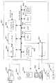
次に、図17のフローチャートを参照してデータ受信装置としての復号器側での処理手順を説明する。
【0075】
データ受信装置は、ステップS101において、RTPパケットの到着を待つ。ステップS102において、到着したRTPパケットのタイムスタンプをRTPT_Sにセットする。また、自装置のシステムクロックによりカウントアップされるRTPタイムスタンプと同じ周期(MPEG2−TSの場合90KHz)のカウンタ値をCNTR_Sにセットする。さらに到着時刻をT_Sにセットする。
【0076】
ステップS103において、予め定められた差分検出時間が経過するのを待機する。この待機処理は、差分検出時間間隔が短すぎると遅延揺らぎの影響により精度が出にくくなるための処理である。なお、データ送信側におけるRTPタイムスタンプの付け方によっては、PCRに同期して同じ値のRTPタイムスタンプが連続する異なるパケットに続いて付与される場合があるので、このパケットがRTPタイムスタンプ群の先頭でない場合は、次のRTPパケットの受信を待機(S105)し、RTPタイムスタンプ群の先頭であることが確認される(S104:Yes)と、ステップS106に進む。。
【0077】
ステップS106では、到着したパケットのRTPタイムスタンプをRTPT_Eにセットする。また、復号器側のシステムクロックによりカウントアップされるRTPタイムスタンプと同じ周期のカウンタ値をCNTR_Eにセットする。さらにその時刻をT_Eにセットする。
【0078】
ステップS107では、前述の[式1]から制御パラメータ値[D]を求め、ステップS108において、制御パラメータ値[D]に基づいて、システムクロックの可変周波数発振器を制御する。
【0079】
ステップS109では、各データ更新処理を実行する。すなわち、RTPT_SにRTPT_Eを、CNTR_SにCNTR_Eを、またT_SにT_Eを代入して、ステップS103に進み、同様の制御を繰り返す。
【0080】
この制御処理を順次繰り返し実行することにより、ネットワークにおける遅延揺らぎが発生した場合においても、また、データ受信側でバッファにデータ蓄積後に処理を実行する場合においても、データ受信側(復号側)のシステムクロックをデータ送信側のシステムクロック、すなわちタイムスタンプによって規定される時刻データに同期させることが可能となり、例えば画像データのリアルタイム再生等が確実に実行される。なお、上述の実施例では、RTPパケットに格納するデータ例としてMPEG2−TSのストリームを挙げたが、上述した方法でシステムクロックを制御する処理は、MPEG2−TSのストリームの処理に限らず、その他の画像、音声他、各種データの転送処理において同様の効果をもたらすものである。
【0081】
図18に、上述の実施例で述べた一連の処理を実行するデータ受信装置のシステム構成例を示す。本発明のシステムで送受信されるデータは、符号化データであり、データ送信装置ではエンコード(符号化)処理が実行され、データ受信装置ではデコード(復号)処理が実行される。符号化されたデータはパケットとしてネットワークを介して送受信する。そのため、データ送信側では、パケット生成(パケタイズ処理)を実行し、データ受信側ではパケット展開(デパケタイズ処理)を実行する。
【0082】
図18に示すデータ受信装置(ex.PC)850は、データ送信処理機能も有するデータ送受信装置として示してある。従ってエンコード(符号化)処理、デコード(復号)処理を実行するとともにパケット生成、展開処理を実行するコーデック851を有する。
【0083】
さらに、通信ネットワークとのインタフェースとして機能するネットワークインタフェース852、マウス837、キーボード836等の入力機器との入出力インタフェース853、ビデオカメラ833、マイク834、スピーカ835等のAVデータ入出力機器からのデータ入出力を行なうAVインタフェース854、ディスプレイ832に対するデータ出力インタフェースとしてのディスプレイ・インタフェース855、各データ入出力インタフェース、コーデック851、ネットワークインタフェース852間のデータ転送制御、その他各種プログラム制御を実行するCPU856、CPU856により制御実行される各種プログラムの格納、データの格納、CPU856のワークエリアとして機能するRAM、ROMからなるメモリ857、データ格納、プログラム格納用の記憶媒体としてのHDD858を有し、それぞれPCIバス859に接続され、相互のデータ送受信が可能な構成を持つ。
【0084】
コーデック851は、図18に示すように、例えばビデオカメラ833からの画像データ、マイク834からの音声データを入力し、符号化処理、パケット生成処理(パケタイズ)を実行し、最終的に符号化データをペイロードとしたパケットを生成する。生成されたパケットは、PCIバス859上に出力され、ネットワークインタフェース852を介してネットワークに出力され、パケットのヘッダに設定された宛先アドレスに配信される。
【0085】
また、HDD858またはメモリ857に格納されたソフトウェアエンコードプログラムに従ってCPU856の制御により、ビデオカメラ833からの画像データ、マイク834からの音声データを符号化してネットワークインタフェース852を介してネットワークに出力する処理も実行する構成としてもよい。
【0086】
一方、ネットワークを介して入力するIPパケット化されたデータは、ネットワークインタフェース852を介して、バス856上に出力されて、メモリ857にバッファリングされた後、コーデック851に入力される。メモリ857からコーデック851に対するデータ(パケット)出力処理、およびコーデック851における復号処理においては、上述の処理によって調整されたシステムクロック859から供給されるクロック信号によって制御が実行される。
【0087】
コーデック851では、入力データのパケット展開処理(デパケタイズ)を実行し、ペイロードとして格納された符号化データを抽出後、復号処理を実行して、ディスプレイ832、スピーカ835において再生、出力する。本構成におけるバッファとしてのメモリ857からのコーデック851に対する出力、コーデック851における処理は、前述のクロック制御によって、データ送信側のクロックに同期させる調整処理がなされたクロックによって制御され、例えばMPEG2−TSパケットに基づく動画再生処理において、データ送信側と同期したリアルタイム再生がエラーなく実行でき、高品質なデータ再生が可能となる。
【0088】
なお、CPU856は、例えばROM等のメモリに格納されたプログラムに限らず、宗太における処理制御を実行する。また、各種のハードディスクに格納されているプログラム、衛星若しくはネットワークから転送され、受信されてインストールされたプログラム等を、RAM(Random Access Memory)等のメモリにロードして実行することも可能である。
【0089】
ここで、本明細書において、プログラムは、1つのコンピュータにより処理されるものであっても良いし、複数のコンピュータによって分散処理されるものであっても良い。さらに、プログラムは、遠方のコンピュータに転送されて実行されるものであっても良い。
【0090】
以上、特定の実施例を参照しながら、本発明について詳解してきた。しかしながら、本発明の要旨を逸脱しない範囲で当業者が該実施例の修正や代用を成し得ることは自明である。すなわち、例示という形態で本発明を開示してきたのであり、限定的に解釈されるべきではない。本発明の要旨を判断するためには、冒頭に記載した特許請求の範囲の欄を参酌すべきである。
【0091】
【発明の効果】
以上、説明してきたように、本発明のデータ受信装置および受信データ処理方法によれば、タイムスタンプを付与した例えばRTP等のデータ通信プロトコルに従ったパケット受信処理において、ネットワークにおける遅延揺らぎが発生した場合においても、また、データ受信側でバッファにデータ蓄積後に処理を実行する場合においても、データ受信側(復号側)のシステムクロックをデータ送信側のシステムクロックに同期させることが可能となり、例えば画像データのリアルタイム再生等を確実に実行することが可能となり、信頼性の高いデータ伝送、高品質なデータ再生が可能となる。
【図面の簡単な説明】
【図1】TCPヘッダ構成を示す図である。
【図2】UDPヘッダ構成を示す図である。
【図3】RTPヘッダ構成を示す図である。
【図4】MPEG2−TS(トランスポートストリーム)について説明する図である。
【図5】トランスポートストリーム(TS)ヘッダ構成について説明する図である。
【図6】トランスポートストリーム(TS)パケットにおけるアダプテーションフィールドについて説明する図である。
【図7】PLLによる制御構成を説明する図である。
【図8】MPEG−TSパケットにおけるRTPタイムスタンプ、PCRとの対応について説明する図である。
【図9】パケット処理におけるバッファリングの影響について説明する図である。
【図10】パケット処理におけるバッファリングの影響を排除するための構成例について説明する図である。
【図11】本発明のデータ受信装置の構成を示す図である。
【図12】本発明のデータ受信装置において処理対象となるパケット構成を示す図である。
【図13】本発明のデータ受信装置における差分解析部の取得するデータ例を示す図である。
【図14】本発明のデータ受信装置における処理シーケンスについて説明する図である。
【図15】本発明のデータ受信装置の構成を示す図である。
【図16】本発明のデータ受信装置における差分解析部の取得するデータ例を示す図である。
【図17】本発明のデータ受信装置における処理手順を説明するフロー図である。
【図18】本発明のデータ受信装置のシステム構成例を示す図である。
【符号の説明】
101 引き算器
102 ローパスフィルタ&ゲイン
103 電圧制御発振器(VCO)
104 カウンタ
201 ネットワーク
202 復号器
203 システムクロック
211 ネットワーク
212 バッファ
213 復号器
214 システムクロック
221 ネットワーク
222 バッファ
223 復号器
224 システムクロック
225 データ量監視部
301 ネットワーク
302 バッファ
303 復号器
304 システムクロック
311 RTPタイムスタンプ取得部
312 差分解析部
313 クロック制御部
401 ネットワーク
402 バッファ
403 復号器
404 システムクロック
411 RTPタイムスタンプ取得部
412 差分解析部
413 クロック制御部
414 可変周波数発振器
809 PCIバス
832 ディスプレイ
833 ビデオカメラ
834 マイク
835 スピーカ
837 マウス
838 キーボード
850 データ送受信装置
851 コーデック
852 ネットワークインタフェース
853 入出力インタフェース
854 AVインタフェース
855 ディスプレイインタフェース
856 CPU
857 メモリ
858 HDD
859 システムクロック[0001]
BACKGROUND OF THE INVENTION
The present invention relates to a data receiving device, a received data processing method, and a computer program. More specifically, the present invention relates to a data receiving apparatus, a received data processing method, and a computer program that enable processing in which a clock on a data transmitting side and a receiving side are synchronized in received packet processing based on a time stamp.
[0002]
[Prior art]
Recently, data transfer such as image and audio data via various communication media such as Internet communication has been actively performed. In particular, in recent years, in the data transfer on the Internet, services based on the stream type transmission method are increasing in addition to the download type transmission method conventionally used. In the download type transmission method, when transmitting multimedia data such as a video file and an audio file, the data file is once downloaded from the distribution server to the storage medium of the receiving terminal and then reproduced from the storage medium. Therefore, this method cannot reproduce the file until the transfer is completed, and is not suitable for long-time reproduction or real-time reproduction.
[0003]
On the other hand, in the latter stream-type transmission method, while data transfer from the transmission side to the reception terminal is performed, reproduction processing of received data is performed in parallel, and Internet telephone / remote video conference / video on It is used for Internet services such as demand.
[0004]
In the stream type transmission method, for example, an MPEG stream generated by MPEG compression processing of image data is stored in an IP (Internet Protocol) packet, transferred over the Internet, and received by each communication terminal such as a PC, PDA, or mobile phone. It is being used in systems that perform such development. Such a technique is effective in video-on-demand and live video streaming distribution, or in real-time communication such as video conferencing and videophone.
[0005]
When using an IP network to reproduce and view audio and video in real time, such as video conferencing and video on demand, in general, a transport such as TCP (Transport Control Protocol) that retransmits when a packet is discarded or a data error occurs The protocol cannot be used because it cannot maintain real-time characteristics. TCP is a protocol for one-to-one communication, and cannot transmit voice / moving image data to a plurality of partners. Therefore, in general, UDP (User Datagram Protocol) is used as a protocol for such applications.
[0006]
UDP is designed to allow application processes to transfer data to other application processes on a remote machine with minimal overhead. Therefore, the information that enters the UDP header is only the source port number, the destination port number, the data length, and the checksum, and there is no field to enter the number indicating the order of the packets as in the TCP header. If the packet order is out of order on the network, processing such as switching the order correctly cannot be performed. Also, there is no field for entering time information such as a time stamp at the time of transmission in both TCP and UDP.
[0007]
The TCP header configuration is shown in FIG. The TCP header includes a source port number, a destination port number, a sequence number indicating the number of bytes indicating the number of bytes from the beginning of the transmission of the data packet, and the next data sent from the other party. Response confirmation number indicating transmission sequence number, header length, flag information consisting of code bits such as TCP segment processing method, window size indicating the number of remaining receivable bytes of data, checksum as a TCP packet reliability guarantee value, It has an urgent pointer indicating the data that requires urgent processing.
[0008]
Details of the UDP header are shown in FIG. UDP is a protocol that provides a connectionless service and has a simple header configuration. As shown in FIG. 2, the UDP header has a source port number, a destination port number, a header length as a data length, a segment length indicating the total number of bytes of the data length, and a checksum as a reliability guarantee value of the UDP packet. . Since UDP has such a simple configuration, the control is simplified.
[0009]
As described above, in data transfer to which the UDP protocol is applied, when the order of packets is out of order on the network, processing such as correctly changing the order cannot be performed. Also, there is no field for entering time information such as a time stamp at the time of transmission in both TCP and UDP.
[0010]
Accordingly, RTP (Real-time Transport Protocol) has been devised. RTP is a transport protocol for transmitting and receiving voice and moving images in real time in an IP network such as the Internet (see RFC1889). In general, RTP is used over UDP. Since RTP transmits a header with a sequence number, a time stamp, and the like, the receiving side can correct the order of the packets and can absorb delay fluctuations in the network. For example, VoIP (Voice) over IP) technology.
[0011]
FIG. 3 shows details of the RTP header in the structure of an IP packet obtained by packetizing data such as MPEG-2 transport stream (TS) using RTP, UDP, and IP. RTP header includes version number (v), padding (P), presence of extension header (X), number of CRSC (Contributing Source), marker information (M), payload type, sequence number, RTP time stamp, synchronous transmission Source (SSRC) identifier and contributing sender (CSRC) identifier fields are provided. The processing time is controlled when the RTP packet is expanded based on the time stamp added to the RTP header, and real-time image or audio reproduction control is possible. For example, an MPEG transport stream as compressed data is stored as a plurality of MPEG-2-TS packets in an IP packet.
[0012]
As described above, the protocol: RTP (Realtime Transport Protocol) is a protocol suitable for the stream type transmission method, and is defined by IETF RFC1889. In data transfer according to RTP, a time stamp is added to a packet as time information, the time relationship between the transmitting side and the receiving side is grasped by referring to the time stamp, and the packet transfer delay fluctuation (jitter) is detected on the data receiving side. ) Etc., and synchronized playback is possible.
[0013]
In addition, MPEG2 (Moving Picture Experts Group-2), an international standard for image compression coding, is a moving image compression method that can be used for all applications of broadcasting, communication, and storage. It is used for.
[0014]
In the MPEG2 system, a plurality of encoded bit streams (ES; Elementary Stream) such as MPEG Video and MPEG Audio can be integrated and multiplexed into one stream. Further, in the MPEG2 system, as shown in FIG. 4 (a), the MPEG2-PS (Program Stream) format (one program constitutes one) assuming transmission from a storage medium with relatively little bit error. As shown in FIG. 4B, two formats of MPEG2-TS (Transport Stream) format (a plurality of programs can be configured by one) assuming a communication line in which a transmission bit error is expected to occur. It prescribes. Since the occurrence of transmission errors is unavoidable in networks such as ATM and Ethernet, MPEG2-TS is generally used for such applications.
[0015]
An MPEG2-TS packet configuration is shown in FIG. The MPEG2-TS packet is a fixed-length packet composed of a 4-byte header and a 184-byte payload for storing data. The TS header is a 1-byte synchronization byte (0x47), a flag indicating the attribute of the TS packet, a 13-bit PID (Packet ID), a scramble control identifier, an adaptation field identifier, and 4 bits used to check the continuity of the packet. It consists of a cyclic counter. Of these, the PID is an identifier that is assigned to each MPEG2-TS packet in order to distinguish the Audio ES and Video ES that make up the MPEG2-TS.
[0016]
Further, as shown in FIG. 6, the TS packet can be transmitted in such a manner that a field called an adaptation field is inserted in the entire data field portion of the payload or before the data. In this adaptation field, private data, PCR (Program Clock Reference), and the like can be stored. This PCR is a counter with a base 33 bits of 90 KHz and an extension 9 bits with a further 1/300 counter, and is a time stamp that realizes 27 MHz. The TS packet having the PCR in the adaptation field has a PID different from that of the Video or Audio stream.
[0017]
PCR is used by the receiving side of MPEG2 data to synchronize the system clock of the decoding circuit with that of the transmitting side. This mechanism will be described below.
[0018]
When the decoder clock frequency is completely the same as the encoder side, video and audio decoding / display follows the transmission side, and the end-to-end delay remains constant over time. Does not match exactly. For this reason, if communication is continued, a phenomenon such as a delay in decoding and display on the receiving side with respect to the transmitting side occurs, which is particularly fatal in applications such as videophones.
[0019]
Therefore, on the decoding side, the system time clock (STC: System Time Clock) of the decoder is made to follow that of the encoder based on the value of the PCR which is the sampled system clock of the encoder. As this method, for example, a PLL (Phase Locked Loop) shown in FIG. 7 is used.
[0020]
In the PLL, when new MPEG data arrives at the decoder, the STC is set to the value of PCR. Each time the PCR arrives at the decoder, the
[0021]
By repeating this loop, the system clock on the decoder side eventually coincides with the encoder side. (This state is called locked.) In MPEG2-TS, it is determined that the PCR transmission interval should be 100 msec or less in order to stabilize the PLL synchronization operation. (700msec for MPEG2-PS)
[0022]
As a standard for transmitting MPEG using RTP described above in an IP network, “RTP Payload Format for MPEG1 / MPEG2 Video” (RFC2250) exists as a standardization proposal protocol. This RFC describes an RTP packet transmission method and a packet encapsulation method. When MPEG-TS is used as data to be inserted into the RTP payload portion, an MPEG2-TS packet is included in one RTP packet. It is supposed to be able to carry multiple items. In addition, the RTP time stamp is set to the same 90 kHz frequency as PCR. That is, as shown in FIG. 8, the RTP time stamp must be synchronized with the base of the PCR.
[0023]
As shown in FIG. 9A, when MPEG2-TS is transmitted using a
[0024]
Further, when the transmission data rate is completely constant, as shown in FIG. 10, even when buffering is performed once using the delay fluctuation absorbing buffer 222 on the receiving side in order to remove the delay fluctuation of the
[0025]
[Problems to be solved by the invention]
The present invention has been made in view of the above-described problems, and removes network delay fluctuations using RTP in data communication processing in which real-time playback is desired, such as video-on-demand and remote video conference. Therefore, the data receiving apparatus which can synchronize the system clock of the decoder with the encoder side even when the receiving side is configured to be buffered once or when the rate is dynamically changed And a received data processing method and a computer program.
[0026]
[Means for Solving the Problems]
The first aspect of the present invention is:
A data receiving device that receives a packet with a time stamp and executes processing of packet storage data,
Comparison processing of time difference data: ΔT_R of a time stamp given to a received packet before and after a predetermined measurement time interval and difference data: ΔT_C of a counter value that generates a reference clock timing of the system clock of the own device is executed. A differential analysis unit to
A clock control unit that generates a control parameter of the system clock based on a difference between time difference data: ΔT_R of a time stamp acquired by the difference analysis unit and difference data of a counter value: ΔT_C;
A system clock for supplying a clock generated based on the control information of the clock control unit to a packet processing means for executing processing of packet storage data;
The data receiving apparatus is characterized by comprising:
[0027]
Furthermore, in one embodiment of the data receiving apparatus of the present invention, the packet processing means includes a decoder that performs a decoding process of the packet stored data, and a buffer means that performs a buffering of the packet stored data. It is the structure.
[0028]
Furthermore, in one embodiment of the data receiving apparatus of the present invention, the clock control unit is configured to calculate the time difference data: ΔT_R of the time stamp acquired by the difference analysis unit and the value of the counter when the measurement time interval is ΔT. Based on the difference from the difference data: ΔT_C, a value calculated by D = (ΔT_R−ΔT_C) / ΔT: D is generated as a control parameter of the system clock.
[0029]
Furthermore, in one embodiment of the data receiving apparatus of the present invention, the clock control unit is configured to calculate the time difference data: ΔT_R of the time stamp acquired by the difference analysis unit and the value of the counter when the measurement time interval is ΔT. Difference data: Based on the difference from ΔT_C, a value calculated by D = (ΔT_R−ΔT_C) / ΔT: D is generated as a control parameter of the system clock. If D> 0, the counter operation is accelerated. The control information for accelerating the system clock is supplied to the system clock. When D <0, the counter operation is delayed, and the control information for delaying the system clock is supplied to the system clock. Features.
[0030]
Furthermore, in an embodiment of the data receiving apparatus of the present invention, the packet to which the time stamp is attached is a packet having an RTP header, and the time stamp is stored in the RTP header based on a clock on the packet transmission side. It is characterized by being data.
[0031]
Furthermore, in an embodiment of the data receiving apparatus of the present invention, the packet to which the time stamp is attached is a packet storing an MPEG2 transport stream, and the decoder performs a decoding process of the MPEG2 transport stream in the system. The present invention is characterized in that the configuration is executed based on control by a clock signal supplied by a clock.
[0032]
Furthermore, in one embodiment of the data receiving apparatus of the present invention, the clock control unit is configured to calculate time difference data of a time stamp: ΔT_R and difference data of a counter value: ΔT_C for each predetermined difference measurement time interval. The system clock control parameter calculation processing based on the difference is repeatedly executed.
[0033]
Furthermore, the second aspect of the present invention provides
A received data processing method for receiving a packet with a time stamp and executing processing of packet storage data,
Time difference data of a time stamp given to a received packet before and after a predetermined measurement time interval: ΔT_R and difference data before and after the measurement time interval of a counter value that generates a reference clock timing of the system clock of its own device: A difference analysis step for executing a comparison process with ΔT_C;
A control parameter generating step for generating a control parameter for the system clock based on the difference between the time difference data of the time stamp acquired in the difference analysis step: ΔT_R and the difference data of the counter value: ΔT_C; A system clock supply step for supplying a clock generated based on the control information generated in the generation step to a packet processing means for executing processing of packet storage data;
A packet processing step for performing packet processing based on the clock;
The received data processing method is characterized by comprising:
[0034]
Furthermore, in one embodiment of the received data processing method of the present invention, the packet processing means includes a decoder that performs a decoding process of the packet stored data, and a buffer means that performs a buffering of the packet stored data. The buffer means executes output processing to the decoder based on the clock supplied in the system clock supply step, and the decoder stores packet storage data based on the clock supplied in the system clock supply step. The decoding process is executed.
[0035]
Further, in one embodiment of the received data processing method of the present invention, the control parameter generation step includes the time difference data: ΔT_R of the time stamp acquired by the difference analysis unit at the measurement time interval: ΔT, and the counter Value difference data: Based on a difference from ΔT_C, a value calculated by D = (ΔT_R−ΔT_C) / ΔT: D is generated as a control parameter of the system clock.
[0036]
Further, in one embodiment of the received data processing method of the present invention, the control parameter generation step includes the time difference data: ΔT_R of the time stamp acquired by the difference analysis unit at the measurement time interval: ΔT, and the counter Value difference data: Based on a difference from ΔT_C, a value calculated by D = (ΔT_R−ΔT_C) / ΔT: D is generated as a control parameter of the system clock. When D> 0, the counter operation is performed The control information for accelerating the system clock is supplied to the system clock. When D <0, the counter operation is delayed, and the control information for delaying the system clock is supplied to the system clock. And
[0037]
Furthermore, in an embodiment of the received data processing method of the present invention, the packet to which the time stamp is attached is a packet storing an MPEG2 transport stream, and the decoder performs a decoding process on the MPEG2 transport stream. This is executed based on control by a clock signal supplied by a system clock.
[0038]
Furthermore, in one embodiment of the received data processing method of the present invention, the control parameter generation step includes time difference data: ΔT_R of a time stamp and difference data of a counter value for each predetermined difference measurement time interval: The system clock control parameter calculation process based on the difference from ΔT_C is repeatedly executed.
[0039]
Furthermore, the third aspect of the present invention provides
A computer program that receives a packet with a time stamp and executes processing of packet storage data,
Time difference data of a time stamp given to a received packet before and after a predetermined measurement time interval: ΔT_R and difference data before and after the measurement time interval of a counter value that generates a reference clock timing of the system clock of its own device: A difference analysis step for executing a comparison process with ΔT_C;
A control parameter generating step for generating a control parameter for the system clock based on the difference between the time difference data of the time stamp acquired in the difference analysis step: ΔT_R and the difference data of the counter value: ΔT_C; A system clock supply step for supplying a clock generated based on the control information generated in the generation step to a packet processing means for executing processing of packet storage data;
A packet processing step for performing packet processing based on the clock;
A computer program comprising:
[0040]
The computer program of the present invention is, for example, a storage medium or communication medium provided in a computer-readable format to a general-purpose computer system capable of executing various program codes, such as a CD, FD, MO, etc. Or a computer program that can be provided by a communication medium such as a network. By providing such a program in a computer-readable format, processing corresponding to the program is realized on the computer system.
[0041]
Other objects, features, and advantages of the present invention will become apparent from a more detailed description based on embodiments of the present invention described later and the accompanying drawings. In this specification, the system is a logical set configuration of a plurality of devices, and is not limited to one in which the devices of each configuration are in the same casing.
[0042]
DETAILED DESCRIPTION OF THE INVENTION
In the data communication using a time-stamped packet, for example, RTP, when the buffering is performed once on the receiving side in order to remove the delay fluctuation of the network, the present invention can decode even if the rate is dynamically changed. A data receiving apparatus having a configuration for synchronizing the system clock of the encoder to the encoder side and a received data processing method are realized.
[0043]
The time stamp added as header information of RTP is synchronized with the PCR representing the system clock on the transmission side on average, even when the delay fluctuation of the network is large. Accordingly, the system clock on the transmission side can be sampled by observing the arrival timing immediately before the RTP delay fluctuation absorbing buffer. Based on this observation data, samples at two points on the time axis are taken, and the increment of the RTP timestamp and the increment of the counter by the system clock on the decoding side are compared, and the system clock on the RTP packet sending side and the RTP packet receiving side This discriminates a deviation from the system clock.
[0044]
First, with reference to FIG. 11, the configuration and processing outline of a data reception side device having a configuration for synchronizing the decoder system clock to the encoder side will be described.
[0045]
For example, a configuration in which data such as MPEG2-TS is stored in an RTP packet and transmitted using a
[0046]
As shown in FIG. 12, the data packet is assumed to be an MPEG over IP packet storing MPEG2-TS and having an RTP header, a UDP header, and an IP header. The RTP header stores a time stamp that is set based on the system clock of the data transmission source.
[0047]
Returning to FIG. 11, the configuration and processing outline of the data receiving side device will be described. The IP packet storing the MPEG2-TS data received via the network is stored in the
[0048]
The time stamp data acquired by the RTP time stamp
[0049]
The difference analysis unit 312 performs a difference [ΔT_R] between two time stamp data before and after the difference detection time interval acquired by the RTP time stamp
[0050]
Each difference data of the difference [ΔT_R] of the time stamp data calculated by the difference analysis unit 312 and the difference [ΔT_C] of the counter is output to the
[0051]
The
[0052]
The generation formula of the control parameter [D] is obtained by the following formula using the difference data [ΔT_R] of the time stamp data and the difference data [ΔT_C] of the counter.
D = (ΔT_R−ΔT_C) / ΔT (Formula 1)
[0053]
If D = 0, the difference data [ΔT_R] of the time stamp data and the difference data [ΔT_C] of the counter are completely equal, and the system clock on the packet transmission side and the system clock on the reception side are synchronized, No counter adjustment is required. If D> 0, it indicates that the difference [ΔT_R] in the time stamp data is larger than the difference [ΔT_C] in the counter, and the counter of the
[0054]
If D <0, this indicates that the difference [ΔT_R] in the time stamp data is smaller than the difference [ΔT_C] in the counter, and the counter of the
[0055]
The
[0056]
Packet transmission / reception between the encoder on the data transmission side and the decoder on the data reception side, and counter correction processing on the reception side will be described with reference to FIG.
[0057]
FIG. 14 shows an upper side of a transmitting side that transmits a packet having an RTP header storing time stamp data, shows a receiving side that receives the packet as a result, and shows the passage of time (t) from left to right. It is a time sequence diagram.
[0058]
At the time of packet transmission, the device on the data transmission side sets RTP counter values [R_0] to [R_N] based on the system clock on the encoder side as RTP time stamps as the transmission time of each packet, and sets the RTP header ( (See FIG. 12).
[0059]
The packet that reaches the receiving side is processed based on RTP counters [C_0] to [C_N] based on the system clock on the decoder side. That is, [R_0] to [R_N] reflect the encoder side clock, and [C_0] to [C_N] are values reflecting the decoder side clock. (Time increase) "is compared to determine which clock is faster or slower, and based on the difference, clock adjustment on the data reception side (decoding side) is executed.
[0060]
By adjusting the decoding side clock to match the data transmission side (encoding side), synchronization of the clocks on the encoder side and the decoder side is realized. For example, in real-time reproduction processing of moving image data, image data is Occurrence of playback disturbance such as temporary stop is prevented.
[0061]
When there is no delay fluctuation of the RTP packet on the communication network, (R_1-R_0) = (C_1-C_0) is satisfied in FIG. 14, and a good reproduction process of the received packet can be performed without adjusting the clock. However, when there is a delay fluctuation of the RTP packet on the communication network, the packet reception interval on the reception side is different from the interval of the time stamp added to the packet on the transmission side.
[0062]
For example, when a delay occurs on the network, a difference per unit time (time increase), that is, an error of a difference between (R_1-R_0) and (C_1-C_0) increases. Therefore, in order to reduce the influence of fluctuation, the comparison of each difference (time increase) is performed from a certain time interval, for example, from arrival of a packet with a time stamp (R_0) to arrival of a packet with a time stamp (R_N). It is necessary to set the time interval as the difference detection time interval.
[0063]
With reference to FIG. 15, the processing on the data reception side (decoder side) will be described in detail. Similar to the configuration described above, the processing packet stores an MPEG2-TS as shown in FIG. 12 described above, and assumes an MPEG over IP packet having an RTP header, a UDP header, and an IP header. An example is a configuration in which a packet having an RTP header to which a time stamp is added is transmitted using a
[0064]
Before a packet received via the network is stored in the
[0065]
The time stamp data acquired by the RTP time stamp
[0066]
The
[0067]
FIG. 16 shows an example of the counter data value that generates the time stamp data acquired by the RTP time stamp
[0068]
That is, from each time [T_S] and time [T_S], time stamp data [RTPT_S] and [RTPT_E] and counter data [CNTR_S] and [CNTR_S] at time [T_E] after a preset difference detection time interval elapses. Based on CNTR_E], the difference between time [T_S] and [T_E] is calculated according to the following equation.
[0069]
RTP timestamp difference (time increment)
ΔT_R = RTPT_E−RTPT_S
Counter difference (counter value increment)
ΔT_C = CNTR_E−CNTR_S
[0070]
The
[0071]
Each difference data of the difference [ΔT_R] of the time stamp data calculated by the
D = (ΔT_R−ΔT_C) / ΔT
Based on the control parameter, the control parameter is generated, and the correction of the counter that generates the reference clock of the
[0072]
Counter control is
If D = 0, no adjustment.
If D> 0, control to speed up counter.
If D <0, control to slow down counter.
Is executed.
[0073]
The
[0074]
Next, the processing procedure on the decoder side as the data receiving apparatus will be described with reference to the flowchart of FIG.
[0075]
In step S101, the data receiving apparatus waits for the arrival of the RTP packet. In step S102, the time stamp of the arrived RTP packet is set in RTPT_S. Further, a counter value having the same period (90 KHz in the case of MPEG2-TS) as the RTP time stamp counted up by the system clock of the own apparatus is set in CNTR_S. Furthermore, the arrival time is set to T_S.
[0076]
In step S103, the process waits for a predetermined difference detection time to elapse. This standby process is a process for making it difficult to obtain accuracy due to the influence of delay fluctuation if the difference detection time interval is too short. Depending on how the RTP time stamp is attached on the data transmission side, the RTP time stamp having the same value may be added to the successive different packets in synchronization with the PCR, so that this packet is the head of the RTP time stamp group. If not, it waits for reception of the next RTP packet (S105), and if it is confirmed that it is the head of the RTP time stamp group (S104: Yes), it proceeds to step S106. .
[0077]
In step S106, the RTP time stamp of the arrived packet is set to RTPT_E. Also, a counter value having the same period as the RTP time stamp counted up by the system clock on the decoder side is set in CNTR_E. Further, the time is set to T_E.
[0078]
In step S107, the control parameter value [D] is obtained from [Expression 1] described above, and in step S108, the variable frequency oscillator of the system clock is controlled based on the control parameter value [D].
[0079]
In step S109, each data update process is executed. That is, RTPT_E is substituted for RTPT_S, CNTR_E is substituted for CNTR_S, and T_E is substituted for T_S. The process proceeds to step S103, and the same control is repeated.
[0080]
A system on the data receiving side (decoding side) can be used even when delay fluctuations in the network occur by executing this control process repeatedly in sequence or when processing is performed after data is stored in the buffer on the data receiving side. It is possible to synchronize the clock with the system clock on the data transmission side, that is, the time data defined by the time stamp, and for example, real-time reproduction of image data or the like is reliably executed. In the above-described embodiment, an MPEG2-TS stream is given as an example of data stored in an RTP packet. However, the process for controlling the system clock by the above-described method is not limited to the MPEG2-TS stream process, and other processes. The same effect is brought about in the transfer processing of various data such as image, sound and the like.
[0081]
FIG. 18 shows a system configuration example of a data receiving apparatus that executes a series of processes described in the above-described embodiment. Data transmitted and received in the system of the present invention is encoded data, and an encoding (encoding) process is executed in the data transmitting apparatus, and a decoding (decoding) process is executed in the data receiving apparatus. The encoded data is transmitted and received as a packet via the network. Therefore, the data transmission side executes packet generation (packetization processing), and the data reception side executes packet expansion (depacketization processing).
[0082]
A data receiving device (ex. PC) 850 shown in FIG. 18 is shown as a data transmitting / receiving device having a data transmission processing function. Accordingly, it has a
[0083]
Further, the
[0084]
As shown in FIG. 18, the
[0085]
In addition, the
[0086]
On the other hand, IP packetized data input via the network is output to the
[0087]
The
[0088]
Note that the
[0089]
Here, in this specification, the program may be processed by one computer or may be distributedly processed by a plurality of computers. Furthermore, the program may be transferred to a remote computer and executed.
[0090]
The present invention has been described in detail above with reference to specific embodiments. However, it is obvious that those skilled in the art can make modifications and substitutions of the embodiments without departing from the gist of the present invention. In other words, the present invention has been disclosed in the form of exemplification, and should not be interpreted in a limited manner. In order to determine the gist of the present invention, the claims section described at the beginning should be considered.
[0091]
【The invention's effect】
As described above, according to the data reception device and the reception data processing method of the present invention, delay fluctuations in the network occur in packet reception processing according to a data communication protocol such as RTP with a time stamp added. Even in the case where the processing is executed after the data is stored in the buffer on the data reception side, the system clock on the data reception side (decoding side) can be synchronized with the system clock on the data transmission side. Real-time reproduction of data and the like can be surely executed, and highly reliable data transmission and high-quality data reproduction are possible.
[Brief description of the drawings]
FIG. 1 is a diagram illustrating a TCP header configuration.
FIG. 2 is a diagram showing a UDP header configuration.
FIG. 3 is a diagram illustrating a configuration of an RTP header.
FIG. 4 is a diagram illustrating MPEG2-TS (transport stream).
FIG. 5 is a diagram illustrating a transport stream (TS) header configuration.
FIG. 6 is a diagram for explaining an adaptation field in a transport stream (TS) packet.
FIG. 7 is a diagram illustrating a control configuration by a PLL.
FIG. 8 is a diagram for explaining the correspondence between RTP time stamps and PCRs in MPEG-TS packets.
FIG. 9 is a diagram illustrating the influence of buffering in packet processing.
FIG. 10 is a diagram illustrating a configuration example for eliminating the influence of buffering in packet processing.
FIG. 11 is a diagram showing a configuration of a data receiving apparatus of the present invention.
FIG. 12 is a diagram showing a packet configuration to be processed in the data receiving apparatus of the present invention.
FIG. 13 is a diagram illustrating an example of data acquired by a difference analysis unit in the data receiving apparatus of the present invention.
FIG. 14 is a diagram illustrating a processing sequence in the data receiving apparatus of the present invention.
FIG. 15 is a diagram showing a configuration of a data receiving apparatus of the present invention.
FIG. 16 is a diagram illustrating an example of data acquired by a difference analysis unit in the data receiving apparatus of the present invention.
FIG. 17 is a flowchart illustrating a processing procedure in the data receiving apparatus of the present invention.
FIG. 18 is a diagram showing a system configuration example of a data receiving apparatus according to the present invention.
[Explanation of symbols]
101 Subtractor
102 Low-pass filter and gain
103 Voltage controlled oscillator (VCO)
104 counter
201 network
202 Decoder
203 System clock
211 network
212 buffers
213 Decoder
214 System clock
221 network
222 buffers
223 decoder
224 system clock
225 Data volume monitoring unit
301 network
302 buffers
303 Decoder
304 System clock
311 RTP timestamp acquisition part
312 Difference analysis unit
313 Clock control unit
401 network
402 buffers
403 Decoder
404 system clock
411 RTP timestamp acquisition part
412 Difference analysis unit
413 Clock control unit
414 Variable frequency oscillator
809 PCI bus
832 display
833 video camera
834 microphone
835 Speaker
837 mouse
838 keyboard
850 data transceiver
851 codec
852 Network interface
853 I / O interface
854 AV interface
855 display interface
856 CPU
857 memory
858 HDD
859 system clock
Claims (14)
Translated fromJapanese予め定められた計測時間間隔前後における受信パケットに付与されたタイムスタンプのタイム差分データ:ΔT_Rと、自装置のシステムクロックの基準クロックタイミングを生成するカウンタ値の差分データ:ΔT_Cとの比較処理を実行する差分解析部と、
前記差分解析部の取得したタイムスタンプのタイム差分データ:ΔT_Rと、カウンタ値の差分データ:ΔT_Cとの、差異に基づいて、前記システムクロックの制御パラメータを生成するクロック制御部と、
前記クロック制御部の制御情報に基づいて生成されるクロックをパケット格納データの処理を実行するパケット処理手段に対して供給するシステムクロックと、
を有することを特徴とするデータ受信装置。A data receiving device that receives a packet with a time stamp and executes processing of packet storage data,
Comparison processing of time difference data: ΔT_R of a time stamp given to a received packet before and after a predetermined measurement time interval and difference data: ΔT_C of a counter value that generates a reference clock timing of the system clock of the own device is executed. A differential analysis unit to
A clock control unit that generates a control parameter of the system clock based on a difference between time difference data: ΔT_R of a time stamp acquired by the difference analysis unit and difference data of a counter value: ΔT_C;
A system clock for supplying a clock generated based on the control information of the clock control unit to a packet processing means for executing processing of packet storage data;
A data receiving apparatus comprising:
前記パケット格納データの復号処理を実行する復号器と、
前記パケット格納データのバッファリングを実行するバッファ手段と、
を含む構成であることを特徴とする請求項1に記載のデータ受信装置。The packet processing means includes
A decoder for performing a decoding process of the packet storage data;
Buffer means for buffering the packet stored data;
The data receiving device according to claim 1, comprising:
計測時間間隔:ΔTのときに、前記差分解析部の取得したタイムスタンプのタイム差分データ:ΔT_Rと、カウンタの値の差分データ:ΔT_Cとの差異に基づいて、
D=(ΔT_R−ΔT_C)/ΔT
によって算出された値:Dを前記システムクロックの制御パラメータとして生成する構成であることを特徴とする請求項1に記載のデータ受信装置。The clock control unit
Based on the difference between the time difference data: ΔT_R of the time stamp acquired by the difference analysis unit and the difference data of the counter value: ΔT_C at the measurement time interval: ΔT,
D = (ΔT_R−ΔT_C) / ΔT
The data receiving apparatus according to claim 1, wherein the data receiving apparatus is configured to generate the value D calculated by the above as a control parameter of the system clock.
計測時間間隔:ΔTのときに、前記差分解析部の取得したタイムスタンプのタイム差分データ:ΔT_Rと、カウンタの値の差分データ:ΔT_Cとの差異に基づいて、
D=(ΔT_R−ΔT_C)/ΔT
によって算出された値:Dを前記システムクロックの制御パラメータとして生成し、
D>0の場合は、前記カウンタ動作を速め、システムクロックを速める制御情報を前記システムクロックに供給し、
D<0の場合は、前記カウンタ動作を遅らせ、システムクロックを遅らせる制御情報を前記システムクロックに供給する処理を実行する構成であることを特徴とする請求項1に記載のデータ受信装置。The clock control unit
Based on the difference between the time difference data: ΔT_R of the time stamp acquired by the difference analysis unit and the difference data of the counter value: ΔT_C at the measurement time interval: ΔT,
D = (ΔT_R−ΔT_C) / ΔT
A value calculated by: D is generated as a control parameter of the system clock;
When D> 0, the control operation for accelerating the counter operation and the system clock is supplied to the system clock,
2. The data receiving apparatus according to claim 1, wherein when D <0, the data receiving apparatus is configured to execute a process of delaying the counter operation and supplying control information for delaying a system clock to the system clock.
前記復号器は、MPEG2トランスポートストリームの復号処理を前記システムクロックの供給するクロック信号による制御に基づいて実行する構成であることを特徴とする請求項1に記載のデータ受信装置。The packet with the time stamp is a packet storing an MPEG2 transport stream,
2. The data receiving apparatus according to claim 1, wherein the decoder is configured to execute a decoding process of the MPEG2 transport stream based on control by a clock signal supplied by the system clock.
予め定められた差分計測時間間隔毎に、タイムスタンプのタイム差分データ:ΔT_Rと、カウンタの値の差分データ:ΔT_Cとの差異に基づくシステムクロックの制御パラメータ算出処理を繰り返し実行する構成であることを特徴とする請求項1に記載のデータ受信装置。The clock control unit
The system clock control parameter calculation process is repeatedly executed based on the difference between the time difference data of the time stamp: ΔT_R and the difference data of the counter value: ΔT_C at each predetermined difference measurement time interval. The data receiving apparatus according to claim 1, wherein
予め定められた計測時間間隔前後における受信パケットに付与されたタイムスタンプのタイム差分データ:ΔT_Rと、自装置のシステムクロックの基準クロックタイミングを生成するカウンタの値の前記計測時間間隔前後における差分データ:ΔT_Cとの比較処理を実行する差分解析ステップと、
前記差分解析ステップにおいて取得したタイムスタンプのタイム差分データ:ΔT_Rと、カウンタの値の差分データ:ΔT_Cとの、差異に基づいて、前記システムクロックの制御パラメータを生成する制御パラメータ生成ステップと、制御パラメータ生成ステップにおいて生成する制御情報に基づいて生成されるクロックをパケット格納データの処理を実行するパケット処理手段に対して供給するシステムクロック供給ステップと、
前記クロックに基づくパケットの処理を実行するパケット処理ステップと、
を有することを特徴とする受信データ処理方法。A received data processing method for receiving a packet with a time stamp and executing processing of packet storage data,
Time difference data of a time stamp given to a received packet before and after a predetermined measurement time interval: ΔT_R and difference data before and after the measurement time interval of a counter value that generates a reference clock timing of the system clock of its own device: A difference analysis step for executing a comparison process with ΔT_C;
A control parameter generating step for generating a control parameter for the system clock based on the difference between the time difference data of the time stamp acquired in the difference analysis step: ΔT_R and the difference data of the counter value: ΔT_C; A system clock supply step for supplying a clock generated based on the control information generated in the generation step to a packet processing means for executing processing of packet storage data;
A packet processing step for performing packet processing based on the clock;
A received data processing method.
前記パケット格納データの復号処理を実行する復号器と、前記パケット格納データのバッファリングを実行するバッファ手段とを含み、
前記バッファ手段は、前記システムクロック供給ステップにおいて供給されるクロックに基づくパケットの復号器への出力処理を実行し、
前記復号器は、前記システムクロック供給ステップにおいて供給されるクロックに基づくパケット格納データの復号処理を実行することを特徴とする請求項8に記載の受信データ処理方法。The packet processing means includes
A decoder for performing decoding processing of the packet storage data; and buffer means for performing buffering of the packet storage data;
The buffer means executes an output process to a decoder based on the clock supplied in the system clock supply step,
9. The received data processing method according to claim 8, wherein the decoder performs a decoding process of packet storage data based on the clock supplied in the system clock supply step.
計測時間間隔:ΔTのときに、前記差分解析部の取得したタイムスタンプのタイム差分データ:ΔT_Rと、カウンタの値の差分データ:ΔT_Cとの差異に基づいて、
D=(ΔT_R−ΔT_C)/ΔT
によって算出された値:Dを前記システムクロックの制御パラメータとして生成することを特徴とする請求項8に記載の受信データ処理方法。The control parameter generation step includes
Based on the difference between the time difference data: ΔT_R of the time stamp acquired by the difference analysis unit and the difference data of the counter value: ΔT_C at the measurement time interval: ΔT,
D = (ΔT_R−ΔT_C) / ΔT
9. The received data processing method according to claim 8, wherein the value D calculated by the step is generated as a control parameter of the system clock.
計測時間間隔:ΔTのときに、前記差分解析部の取得したタイムスタンプのタイム差分データ:ΔT_Rと、カウンタの値の差分データ:ΔT_Cとの差異に基づいて、
D=(ΔT_R−ΔT_C)/ΔT
によって算出された値:Dを前記システムクロックの制御パラメータとして生成し、
D>0の場合は、前記カウンタ動作を速め、システムクロックを速める制御情報を前記システムクロックに供給し、
D<0の場合は、前記カウンタ動作を遅らせ、システムクロックを遅らせる制御情報を前記システムクロックに供給する処理を実行することを特徴とする請求項8に記載の受信データ処理方法。The control parameter generation step includes
Based on the difference between the time difference data: ΔT_R of the time stamp acquired by the difference analysis unit and the difference data of the counter value: ΔT_C at the measurement time interval: ΔT,
D = (ΔT_R−ΔT_C) / ΔT
A value calculated by: D is generated as a control parameter of the system clock;
When D> 0, the control operation for accelerating the counter operation and the system clock is supplied to the system clock,
9. The received data processing method according to claim 8, wherein when D <0, a process of delaying the counter operation and supplying control information for delaying a system clock to the system clock is executed.
前記復号器は、MPEG2トランスポートストリームの復号処理を前記システムクロックの供給するクロック信号による制御に基づいて実行することを特徴とする請求項8に記載の受信データ処理方法。The packet with the time stamp is a packet storing an MPEG2 transport stream,
9. The received data processing method according to claim 8, wherein the decoder executes a decoding process of the MPEG2 transport stream based on control by a clock signal supplied by the system clock.
予め定められた差分計測時間間隔毎に、タイムスタンプのタイム差分データ:ΔT_Rと、カウンタの値の差分データ:ΔT_Cとの差異に基づくシステムクロックの制御パラメータ算出処理を繰り返し実行する構成であることを特徴とする請求項8に記載の受信データ処理方法。The control parameter generation step includes
The system clock control parameter calculation process is repeatedly executed based on the difference between the time difference data of the time stamp: ΔT_R and the difference data of the counter value: ΔT_C at each predetermined difference measurement time interval. The received data processing method according to claim 8, wherein:
予め定められた計測時間間隔前後における受信パケットに付与されたタイムスタンプのタイム差分データ:ΔT_Rと、自装置のシステムクロックの基準クロックタイミングを生成するカウンタの値の前記計測時間間隔前後における差分データ:ΔT_Cとの比較処理を実行する差分解析ステップと、
前記差分解析ステップにおいて取得したタイムスタンプのタイム差分データ:ΔT_Rと、カウンタの値の差分データ:ΔT_Cとの、差異に基づいて、前記システムクロックの制御パラメータを生成する制御パラメータ生成ステップと、制御パラメータ生成ステップにおいて生成する制御情報に基づいて生成されるクロックをパケット格納データの処理を実行するパケット処理手段に対して供給するシステムクロック供給ステップと、
前記クロックに基づくパケットの処理を実行するパケット処理ステップと、
を具備することを特徴とするコンピュータ・プログラム。A computer program that receives a packet with a time stamp and executes processing of packet storage data,
Time difference data of a time stamp given to a received packet before and after a predetermined measurement time interval: ΔT_R and difference data before and after the measurement time interval of a counter value that generates a reference clock timing of the system clock of its own device: A difference analysis step for executing a comparison process with ΔT_C;
A control parameter generating step for generating a control parameter for the system clock based on the difference between the time difference data of the time stamp acquired in the difference analysis step: ΔT_R and the difference data of the counter value: ΔT_C; A system clock supply step for supplying a clock generated based on the control information generated in the generation step to a packet processing means for executing processing of packet storage data;
A packet processing step for performing packet processing based on the clock;
A computer program comprising:
Priority Applications (1)
| Application Number | Priority Date | Filing Date | Title |
|---|---|---|---|
| JP2002049181AJP3922047B2 (en) | 2002-02-26 | 2002-02-26 | Data receiving apparatus, received data processing method, and computer program |
Applications Claiming Priority (1)
| Application Number | Priority Date | Filing Date | Title |
|---|---|---|---|
| JP2002049181AJP3922047B2 (en) | 2002-02-26 | 2002-02-26 | Data receiving apparatus, received data processing method, and computer program |
Publications (2)
| Publication Number | Publication Date |
|---|---|
| JP2003249922A JP2003249922A (en) | 2003-09-05 |
| JP3922047B2true JP3922047B2 (en) | 2007-05-30 |
Family
ID=28661759
Family Applications (1)
| Application Number | Title | Priority Date | Filing Date |
|---|---|---|---|
| JP2002049181AExpired - Fee RelatedJP3922047B2 (en) | 2002-02-26 | 2002-02-26 | Data receiving apparatus, received data processing method, and computer program |
Country Status (1)
| Country | Link |
|---|---|
| JP (1) | JP3922047B2 (en) |
Cited By (1)
| Publication number | Priority date | Publication date | Assignee | Title |
|---|---|---|---|---|
| US11936713B2 (en)* | 2018-12-28 | 2024-03-19 | Kabushiki Kaisha Toshiba | Broadcasting system, encoder, multiplexing apparatus, multiplexing method, system switching apparatus, and synchronization control apparatus |
Families Citing this family (18)
| Publication number | Priority date | Publication date | Assignee | Title |
|---|---|---|---|---|
| JP4694969B2 (en) | 2004-01-07 | 2011-06-08 | パナソニック株式会社 | Data receiver |
| JP4643276B2 (en)* | 2005-01-11 | 2011-03-02 | 株式会社東芝 | Wireless receiver |
| US8238376B2 (en) | 2005-04-13 | 2012-08-07 | Sony Corporation | Synchronized audio/video decoding for network devices |
| JP2007104347A (en)* | 2005-10-05 | 2007-04-19 | Matsushita Electric Ind Co Ltd | Clock synchronization system and method in audio transmission system |
| JP2008035197A (en)* | 2006-07-28 | 2008-02-14 | Sumitomo Electric Ind Ltd | Clock circuit, video processing apparatus, and clock adjustment method |
| JP4679502B2 (en)* | 2006-12-18 | 2011-04-27 | Kddi株式会社 | Voice packet reproducing apparatus, communication terminal and program having clock correction function |
| JP4475273B2 (en) | 2006-12-21 | 2010-06-09 | ソニー株式会社 | Information processing apparatus and method |
| JP4701189B2 (en)* | 2007-01-19 | 2011-06-15 | 富士通株式会社 | Data processing apparatus, data processing method, and data processing program |
| US8233432B2 (en)* | 2007-08-31 | 2012-07-31 | Silicon Image, Inc. | Ensuring physical locality of entities sharing data |
| JP5212473B2 (en)* | 2008-06-26 | 2013-06-19 | 富士通セミコンダクター株式会社 | VIDEO / AUDIO DATA OUTPUT DEVICE AND VIDEO / AUDIO DATA OUTPUT METHOD |
| JP2010154133A (en)* | 2008-12-24 | 2010-07-08 | Toshiba Corp | Digital broadcast receiving apparatus |
| JP5544863B2 (en)* | 2009-12-17 | 2014-07-09 | 富士通株式会社 | Reception device, reception method, and reception program |
| JP5720285B2 (en)* | 2011-02-14 | 2015-05-20 | 日本電気株式会社 | Streaming system |
| JP2012249040A (en)* | 2011-05-27 | 2012-12-13 | Hitachi Ulsi Systems Co Ltd | Network connection reception side device and time synchronization system |
| JP5616922B2 (en)* | 2012-04-16 | 2014-10-29 | 株式会社ソニー・コンピュータエンタテインメント | Synchronization signal adjustment device, synchronization signal adjustment method, video display device, and synchronization signal generation device |
| US20180359303A1 (en)* | 2015-03-05 | 2018-12-13 | Mitsubishi Electric Corporation | Data processing apparatus, data processing method, and computer readable medium |
| US11844038B2 (en)* | 2020-09-15 | 2023-12-12 | Texas Instruments Incorporated | Synchronization of wireless network nodes for efficient communications |
| CN112601077B (en)* | 2020-12-11 | 2022-07-26 | 杭州当虹科技股份有限公司 | Automatic encoder delay measuring method based on audio |
- 2002
- 2002-02-26JPJP2002049181Apatent/JP3922047B2/ennot_activeExpired - Fee Related
Cited By (1)
| Publication number | Priority date | Publication date | Assignee | Title |
|---|---|---|---|---|
| US11936713B2 (en)* | 2018-12-28 | 2024-03-19 | Kabushiki Kaisha Toshiba | Broadcasting system, encoder, multiplexing apparatus, multiplexing method, system switching apparatus, and synchronization control apparatus |
Also Published As
| Publication number | Publication date |
|---|---|
| JP2003249922A (en) | 2003-09-05 |
Similar Documents
| Publication | Publication Date | Title |
|---|---|---|
| JP3922047B2 (en) | Data receiving apparatus, received data processing method, and computer program | |
| EP0987894B1 (en) | A dejittering and clock recovery technique for real-time audio/visual network applications | |
| JP4407007B2 (en) | Data transmission apparatus and method | |
| US7983345B2 (en) | Content receiving apparatus, video/audio output timing control method, and content provision system | |
| US7545794B2 (en) | Timestamping network controller for streaming media applications | |
| US7680153B2 (en) | Method and device for stream synchronization of real-time multimedia transport over packet network | |
| CN101371488B (en) | A method and system for synchronizing between different media streams | |
| JP4216195B2 (en) | Sending a stream over an asynchronous network | |
| US20080310316A1 (en) | Surrogate Stream for Monitoring Realtime Media | |
| CN101184035B (en) | Broadcast TS distribution system, distribution device, user terminal device, and distribution method | |
| JP2009010966A (en) | Receiving a stream over an asynchronous network | |
| WO2005067252A1 (en) | Data reception device | |
| CN1969563B (en) | Control method and system for speed limiting of program clock reference dejitter | |
| JP4042396B2 (en) | Data communication system, data transmission apparatus, data reception apparatus and method, and computer program | |
| JP3906678B2 (en) | Data communication system, data transmission apparatus, data reception apparatus and method, and computer program | |
| JP4561240B2 (en) | Data processing apparatus, data processing method, and data transmission / reception system | |
| JP6848797B2 (en) | Broadcast retransmission device, broadcast receiver, broadcast retransmission method, broadcast reception method, broadcast retransmission program and broadcast reception program | |
| KR101924183B1 (en) | Multimedia transmission apparatus having genlock function | |
| Wagner et al. | Towards an RTP Profile for IPTV | |
| JP2020170914A (en) | Switching method, ip retransmission system, ip retransmission device, and control device | |
| Fernando | MMT: the next-generation media transport standard | |
| EP2093926A1 (en) | Method of receiving and method of sending data over a network | |
| WO2006040320A1 (en) | Method to add precision in transmitting mpeg stream over ip and device implementing the method | |
| Montagud et al. | Implementation and evaluation of an M/S scheme for inter-destination multimedia synchronization (IDMS) | |
| Won et al. | Estimation of Network Jitter Using Delivery Instant Parameter of MPEG MMT Protocol |
Legal Events
| Date | Code | Title | Description |
|---|---|---|---|
| A621 | Written request for application examination | Free format text:JAPANESE INTERMEDIATE CODE: A621 Effective date:20050221 | |
| A977 | Report on retrieval | Free format text:JAPANESE INTERMEDIATE CODE: A971007 Effective date:20070115 | |
| TRDD | Decision of grant or rejection written | ||
| A01 | Written decision to grant a patent or to grant a registration (utility model) | Free format text:JAPANESE INTERMEDIATE CODE: A01 Effective date:20070130 | |
| A61 | First payment of annual fees (during grant procedure) | Free format text:JAPANESE INTERMEDIATE CODE: A61 Effective date:20070212 | |
| FPAY | Renewal fee payment (event date is renewal date of database) | Free format text:PAYMENT UNTIL: 20100302 Year of fee payment:3 | |
| FPAY | Renewal fee payment (event date is renewal date of database) | Free format text:PAYMENT UNTIL: 20110302 Year of fee payment:4 | |
| FPAY | Renewal fee payment (event date is renewal date of database) | Free format text:PAYMENT UNTIL: 20120302 Year of fee payment:5 | |
| FPAY | Renewal fee payment (event date is renewal date of database) | Free format text:PAYMENT UNTIL: 20120302 Year of fee payment:5 | |
| FPAY | Renewal fee payment (event date is renewal date of database) | Free format text:PAYMENT UNTIL: 20130302 Year of fee payment:6 | |
| FPAY | Renewal fee payment (event date is renewal date of database) | Free format text:PAYMENT UNTIL: 20140302 Year of fee payment:7 | |
| R250 | Receipt of annual fees | Free format text:JAPANESE INTERMEDIATE CODE: R250 | |
| LAPS | Cancellation because of no payment of annual fees |