JP3920155B2 - Flyer - Google Patents
FlyerDownload PDFInfo
- Publication number
- JP3920155B2 JP3920155B2JP2002161771AJP2002161771AJP3920155B2JP 3920155 B2JP3920155 B2JP 3920155B2JP 2002161771 AJP2002161771 AJP 2002161771AJP 2002161771 AJP2002161771 AJP 2002161771AJP 3920155 B2JP3920155 B2JP 3920155B2
- Authority
- JP
- Japan
- Prior art keywords
- oil
- tank
- deterioration
- electrode terminal
- fryer
- Prior art date
- Legal status (The legal status is an assumption and is not a legal conclusion. Google has not performed a legal analysis and makes no representation as to the accuracy of the status listed.)
- Expired - Fee Related
Links
- 230000006866deteriorationEffects0.000claimsdescription37
- 238000001514detection methodMethods0.000claimsdescription10
- 238000005259measurementMethods0.000claimsdescription5
- 238000000034methodMethods0.000description6
- 238000010438heat treatmentMethods0.000description4
- 230000007423decreaseEffects0.000description3
- 238000010586diagramMethods0.000description3
- 238000005187foamingMethods0.000description2
- 239000004615ingredientSubstances0.000description2
- 230000001678irradiating effectEffects0.000description2
- 239000002699waste materialSubstances0.000description2
- XLYOFNOQVPJJNP-UHFFFAOYSA-NwaterSubstancesOXLYOFNOQVPJJNP-UHFFFAOYSA-N0.000description2
- 238000010521absorption reactionMethods0.000description1
- 230000033228biological regulationEffects0.000description1
- 230000015556catabolic processEffects0.000description1
- 238000004140cleaningMethods0.000description1
- 238000010411cookingMethods0.000description1
- 230000003247decreasing effectEffects0.000description1
- 238000006731degradation reactionMethods0.000description1
- 230000000694effectsEffects0.000description1
- 238000012986modificationMethods0.000description1
- 230000004048modificationEffects0.000description1
- 238000012856packingMethods0.000description1
- 238000012545processingMethods0.000description1
- 239000000779smokeSubstances0.000description1
- 238000012546transferMethods0.000description1
Images


Landscapes
- Frying-Pans Or Fryers (AREA)
Description
Translated fromJapanese【0001】
【発明の属する技術分野】
この発明は、タンク内の油により食材を加熱調理するフライヤに係り、特に油の劣化検知に関する。
【0002】
【従来の技術】
一般に、フライヤには油を収容するタンクとタンク内に収容された油を加熱するための加熱部とが備えられており、食材が加熱されているタンク内の油に投下されてフライ調理される。フライ調理を繰り返すことにより油が劣化するため油の交換作業が必要になる。従来、この油の劣化具合即ち油の交換時期はタンク内の油の臭いや色により判断されていた。しかし、この方法による劣化具合の判断は迅速に行うことができるものの、人の感覚による判断であることから、人により区々な判断がなされたり、体調等によって判断が左右されたりする等、非常に正確性を欠くものであった。
このため、以下のような装置及び方法が提案されている。すなわち、
(A)特開平6−141984号公報に開示されるフライヤであって、加熱部として油を加熱するヒータの通電時間を積算し、所定時間に到達すると油の交換時期であると判断するフライヤ、
(B)特開平6−178731号公報に開示される劣化検出装置及び同装置付きフライヤであって、透過紫外線を発生する発光素子を備え、透過紫外線を油に照射してその吸収度合いを測定し、その度合いにより油の劣化を判断する劣化検出装置及び同装置付きフライヤ、及び
(C)特許第3107499号公報に開示される劣化度を検知する方法であって、油の泡立ちの量を油面の照度から検知し、その度合いにより油の劣化を検知する方法、である。
【0003】
【発明が解決しようとする課題】
しかしながら、(A)〜(C)の従来技術にはそれぞれ以下に示すような問題点があった。
(A)のフライヤでは、ヒータ通電時間だけで単純に交換時期を判断するが、油の劣化は、加熱され高温になること、水分が混入してくること、食材の成分が混入してくること、高温の油の油面が空気と触れること等の様々な要因により起こるものであるため、単純にヒータ通電時間だけでは油の劣化を判断することはできない。
(B)の劣化検出装置及び同装置付きフライヤでは、劣化検出装置自体を小型の機種のフライヤに内蔵することが困難であるため、フライヤとは別の装置として制作し、その後にドッキングさせなければならない。また、若干大きめの自立タイプの機種のフライヤに内蔵させることは可能だが、劣化検出装置自体が高価であることから、フライヤ自体の大幅なコストアップは避けられない。
(C)の劣化度を検知する方法では、スポットライト等で油に照光しつつ、照度計で泡の量を検知するが、実際の厨房内で油に照射する光の強さを一定に保つことが困難であるため、正確な測定ができないおそれがある。また、照度は油面より上方からでしか検出できないのでフライ作業中に発生する油煙や水蒸気等による汚れが照度計等に付着して測定の妨げになる。また、フライ調理中にしか泡立ちの判断ができない。更に、照度計自体が高価であるため、フライヤ自体の大幅なコストアップは避けられないといった課題があった。
【0004】
本発明は以上のような問題点を解決するためになされたもので、大幅なコスト増加を伴うことなく油の劣化具合を正確に測定することができるフライヤを提供することを目的とする。
【0005】
【課題を解決するための手段】
上述の目的を達成するために、本発明に係るフライヤは、タンク内の油に浸けられる電極端子と、電極端子を介してタンク内の油の電気抵抗値を計測し、この油の劣化を検出する油劣化検出手段と、タンク内の油の電気抵抗値が所定状態にある時間を計測するタイマとを備え、油劣化検出手段は、タイマの計測状態に応じて油の劣化の有無を規定するものである。
また、電極端子は、タンク内におけるホットゾーンの油に浸けられてもよく、また、タンク内におけるタンク底面を外れたコールドゾーンの油に浸けられてもよい。
また、油劣化検出手段により油の劣化が検出された際にそれを利用者に報知する報知手段をさらに備えてもよい。
【0006】
【発明の実施の形態】
以下、本発明に係るフライヤの実施の形態を添付図面に基づいて説明する。
実施の形態1.
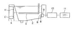
図1に実施の形態1に係るフライヤの全体構成を示す。フライヤは箱状のキャビネット1を有し、このキャビネット1の上部に油を貯留するタンク2を備えている。タンク2内には油を加熱するためのヒータ3が設けられており、このヒータ3は電装箱4内に収容された電気部品等により通電制御される。ヒータ3が設けられている深さより上方の油はヒータ3の熱が伝わりやすいので高温になりやすく、ヒータ3より上方は一般にホットゾーンHと呼ばれている。一方、ヒータ3より下方の油はヒータ3の熱が伝わりにくく比較的低温になりやすいため、ヒータ3より下方は一般にコールドゾーンCと呼ばれている。タンク2の底面にはバルブ5を介装させた排油管6が接続されており、この底面は排油管6に向けて下方に傾斜している。排油管6の下方には、廃油を収容するための廃油タンク7が配設されている。
【0007】
図2にこのフライヤのタンク近傍の構成を示す。タンク2内の側壁には二本の電極端子8が、ホットゾーンHの油に浸かるように配設されており、この電極端子8はタンク2の側壁の外側に配置された電極本体9に固定されている。電極端子8はタンク2に設けられた穴を通して電極本体9と接続しており、穴と電極端子8との隙間は油漏れがないようにパッキン等でシールされている。また、電極本体9は抵抗検出器を含む油劣化検出手段としての制御装置10に接続されている。さらに、制御装置10には報知手段としてブザー11が接続されている。
【0008】
次に、実施の形態1に係るフライヤの動作を説明する。電極本体9により電極端子8に電源が供給され、二本の電極端子8間の電気抵抗値Rが制御装置10で検知される。油がまだ使用されていない状態では電気抵抗値Rは無限大であるが、油の使用すなわちフライ調理を続けていくうちに徐々に水分や被調理物の成分等が油に混入し電気抵抗値Rは徐々に低下していく。すなわち、油の劣化に伴って油の電気抵抗値Rが低下する。このため、制御装置10では、電気抵抗値Rを検知し、この電気抵抗値Rが所定値Rcまで低下したとき油が劣化したと判断する。制御装置10で油が劣化したと判断されたときブザー11が作動して利用者に油が劣化したことを報知する。
【0009】
このように、電極端子8及び電極本体9等を介して油の電気抵抗値Rが測定され、これにより油の劣化が検出されるので安価にしかも正確に劣化の検出を行うことができる。また、電極端子8及び電極本体9等は取り付けスペースが非常に小さく固定も容易であることからフライヤ自体に内蔵することが非常に容易に可能である。また、タンク2内に二本の電極端子8が突出しているだけなので、タンク2内の掃除も容易である。
また、フライ調理の際に発生する揚げカスはタンク2下部のコールドゾーンCに沈殿していくため、ホットゾーンHに電極端子8を配置することで、揚げカスの影響を受けにくく正確な検知を行うことができる。結果として、適切な油の交換時期や差し油時期がわかるため、被調理物の品質を高品質に保つことができる。
【0010】
実施の形態2.
次に、実施の形態2に係るフライヤの構成を図3に基づいて説明する。このフライヤは、図2に示した実施の形態1に係るフライヤにおいて、電極端子8をホットゾーンHの油に浸るようにするかわりにコールドゾーンCの油に浸るようにしたものである。すなわち、電極端子8及び電極本体9をヒータ3より下方の側壁に配置するようにしたものである。電気フライヤの場合は、ホットゾーンHの油温を約200℃まで上げてフライ調理を行うが、このときのコールドゾーンCの油温は約50〜100℃である。このため、コールドゾーンCに設けた電極端子8は高い耐熱性が要求されず、耐熱加工が不要であることからより安価に製造することができる。また、揚げカスはタンク2底面に沈殿するので電極端子8を底面を外れた側面に設けることでその影響を少なくすることができる。
【0011】
実施の形態3.
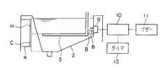
次に実施の形態3に係るフライヤの構成を図4に基づいて説明する。このフライヤは、図2に示した実施の形態1に係るフライヤにおいて制御装置10にタイマ12を接続したものである。このタイマ12は低下していく電気抵抗値Rが所定値Rcに到達した時点でカウントをスタートし、電気抵抗値Rが継続して所定値Rc以下の状態を、一定時間T、計測した場合には制御装置10は、油が劣化したと判断し、ブザー11を作動させる。このように一定時間T継続して電気抵抗値Rが所定値Rc以下の場合に、油が劣化したと判断されるようにしているので、電気抵抗値Rの変動が大きくなるような加熱調理中でも正確に油の劣化を検知することができる。
【0012】
なお、本発明は、上述した実施の形態に限定されるものではなく、様々な改変を施すことも可能である。
すなわち、本発明に係るフライヤの電極端子及び油劣化検出手段は電気フライヤだけでなくガスフライヤなど他の形式のフライヤに適用することも可能である。また、コールドゾーンCに電極端子8及び電極本体9を設けた実施の形態2に実施の形態3のタイマ12を設けて実施することも可能である。
また、報知手段は、利用者に油の劣化を知らしめる手段であればよく、ブザー11に限られずランプやセグメント等でもよい。また、例えば、報知手段の作動後に、リセットボタンを押す等の所定の動作を行わないと再起動しないような報知態様でもよい。
また、タイマを用いた油劣化検出手段は電気抵抗値Rが一定時間T継続して所定値Rc以下になった場合に限らず、例えば電気抵抗値Rが一定時間T内に所定回数、所定値Rc以下になった場合に油が劣化したと判断するなど、他の規定方法でもよい。
また、ホットゾーンHにおける電極端子8の取り付け位置は、適正油面の下限値より下方であれば、タンク2の前面、背面及び側面のどこに取り付けてもよく、また、タンク2内のホットゾーンHに浸かるように吊して設けるようにしてもよい。また、コールドゾーンCにおける電極端子8の取り付け位置も適正油面の下限値より下方であって揚げカスが沈殿するタンク底面以外の面であれば、タンクの前面、背面及び側面のどこに取り付けてもよく、同様に吊して設ける様態でもよい。
【0013】
【発明の効果】
以上説明したように、本発明のフライヤによれば、タンク内の油に浸された電極端子を介して、タンク内の油の電気抵抗値を計測し油の劣化を検出する油劣化検出手段と、タンク内の油の電気抵抗値が所定状態にある時間を計測するタイマとを備え、油劣化検出手段は、タイマの計測状態に応じて油の劣化の有無を規定するので、大幅なコスト増加を伴うことなく、油の劣化具合を正確に測定することができる。
【図面の簡単な説明】
【図1】 本発明の実施の形態1に係るフライヤを模式的に示す側面図である。
【図2】 実施の形態1に係るフライヤのタンク近傍の構成を模式的に示す図である。
【図3】 実施の形態2に係るフライヤのタンク近傍の構成を模式的に示す図である。
【図4】 実施の形態3に係るフライヤのタンク近傍の構成を模式的に示す図である。
【符号の説明】
1…キャビネット、2…タンク、3…ヒータ、4…電装箱、5…バルブ、6…排油管、7…排油タンク、8…電極端子、9…電極本体部、10…制御部、11…ブザー、12…タイマ、C…コールドゾーン、H…ホットゾーン。[0001]
BACKGROUND OF THE INVENTION
The present invention relates to a fryer that cooks food with oil in a tank, and more particularly to detection of oil deterioration.
[0002]
[Prior art]
Generally, a fryer is provided with a tank for storing oil and a heating unit for heating the oil stored in the tank, and the food is dropped into the oil in the heated tank to be fried. . Since the oil deteriorates due to repeated frying, it is necessary to replace the oil. Conventionally, the degree of deterioration of the oil, that is, the replacement time of the oil has been determined based on the odor and color of the oil in the tank. However, although it is possible to quickly determine the degree of deterioration by this method, it is a judgment based on human senses. Was lacking in accuracy.
For this reason, the following apparatuses and methods have been proposed. That is,
(A) A fryer disclosed in JP-A-6-141984, which integrates energization time of a heater that heats oil as a heating unit, and determines that it is time to replace oil when a predetermined time is reached,
(B) A deterioration detection device and a fryer with the same device disclosed in Japanese Patent Laid-Open No. 6-177871, comprising a light emitting element for generating transmitted ultraviolet rays, and measuring the degree of absorption by irradiating the transmitted ultraviolet rays with oil. , A deterioration detecting device for judging deterioration of oil according to the degree thereof, a fryer with the device, and a method for detecting the degree of deterioration disclosed in Japanese Patent No. 3107499, wherein the amount of foaming of oil This is a method of detecting deterioration of oil and detecting deterioration of oil according to the degree.
[0003]
[Problems to be solved by the invention]
However, each of the prior arts (A) to (C) has the following problems.
In the flyer (A), the replacement time is determined simply by the heater energization time. However, the deterioration of the oil is heated to a high temperature, water is mixed, and ingredients of the food are mixed. Since it is caused by various factors such as contact of the oil surface of the hot oil with the air, it is not possible to judge the deterioration of the oil only by the heater energization time.
In the deterioration detection device and the flyer with the same device in (B), it is difficult to incorporate the deterioration detection device itself into a small model flyer, so it must be manufactured as a device separate from the flyer and then docked. Don't be. Although it can be built in a slightly larger self-supporting type flyer, the cost of the flyer itself is inevitable because the deterioration detection device itself is expensive.
In the method of detecting the degree of deterioration in (C), the amount of bubbles is detected with an illuminometer while illuminating the oil with a spotlight or the like, but the intensity of light irradiating the oil in an actual kitchen is kept constant. Therefore, there is a possibility that accurate measurement cannot be performed. In addition, since the illuminance can only be detected from above the oil level, dirt due to oil smoke or water vapor generated during the frying operation adheres to the illuminance meter and hinders measurement. Also, foaming can only be judged during frying. Furthermore, since the illuminance meter itself is expensive, there has been a problem that a significant increase in cost of the fryer itself is unavoidable.
[0004]
The present invention has been made to solve the above-described problems, and an object of the present invention is to provide a fryer capable of accurately measuring the degree of deterioration of oil without significantly increasing the cost.
[0005]
[Means for Solving the Problems]
In order to achieve the above-mentioned object, the flyer according to the present invention measures the electrical resistance value of the oil in the tank via the electrode terminal immersed in the oil in the tank, and detects the deterioration of the oil. And atimer that measures the time during which the electrical resistance value of the oil in the tank is in a predetermined state. The oil deterioration detection unit defines whether or not the oil has deteriorated according to the measurement state of the timer. Is.
The electrode terminal may be immersed in oil in a hot zone in the tank, or may be immersed in oil in a cold zone outside the tank bottom surface in the tank.
Moreover, when the oil deterioration is detected by the oil deterioration detecting means, a notifying means for notifying the user of the oil deterioration may be further provided.
[0006]
DETAILED DESCRIPTION OF THE INVENTION
Embodiments of a flyer according to the present invention will be described below with reference to the accompanying drawings.
Embodiment 1 FIG.
FIG. 1 shows the overall configuration of the flyer according to the first embodiment. The flyer has a box-shaped cabinet 1 and is provided with a
[0007]
FIG. 2 shows the configuration of the flyer near the tank. Two
[0008]
Next, the operation of the flyer according to Embodiment 1 will be described. Power is supplied to the
[0009]
In this way, the electrical resistance value R of the oil is measured through the
In addition, since fried debris generated during frying is settled in the cold zone C at the bottom of the
[0010]
Next, the structure of the flyer according to
[0011]
Next, the structure of the flyer according to
[0012]
The present invention is not limited to the embodiment described above, and various modifications can be made.
That is, the electrode terminal and the oil deterioration detecting means of the flyer according to the present invention can be applied not only to an electric flyer but also to other types of fryer such as a gas fryer. Further, the
Further, the notification means is not limited to the buzzer 11 and may be a lamp, a segment, or the like as long as it is a means for notifying the user of oil deterioration. Further, for example, a notification mode may be employed in which a restart is not performed unless a predetermined operation such as pressing a reset button is performed after the notification unit is activated.
The oil deterioration detecting means using a timer is not limited to the case where the electric resistance value R continues for a certain time T and becomes equal to or less than the predetermined value Rc. Other regulation methods may be used, such as determining that the oil has deteriorated when Rc or less.
In addition, the
[0013]
【The invention's effect】
As described above, according to the flyer of the present invention, the oil deterioration detecting means for measuring the electric resistance value of the oil in the tank and detecting the deterioration of the oil through the electrode terminal immersed in the oil in the tank,And a timer that measures the time that the electrical resistance value of the oil in the tank is in a predetermined state, and the oil deterioration detecting means regulates whether or not the oil has deteriorated according to the measurement state of the timer, so that the cost is significantly increased. Without being accompanied, it is possible to accurately measure the degree of deterioration of the oil.
[Brief description of the drawings]
FIG. 1 is a side view schematically showing a flyer according to Embodiment 1 of the present invention.
FIG. 2 is a diagram schematically showing a configuration in the vicinity of the tank of the flyer according to the first embodiment.
FIG. 3 is a diagram schematically showing a configuration in the vicinity of a tank of a fryer according to a second embodiment.
FIG. 4 is a diagram schematically showing a configuration in the vicinity of a tank of a fryer according to a third embodiment.
[Explanation of symbols]
DESCRIPTION OF SYMBOLS 1 ... Cabinet, 2 ... Tank, 3 ... Heater, 4 ... Electrical equipment box, 5 ... Valve, 6 ... Oil drain pipe, 7 ... Oil drain tank, 8 ... Electrode terminal, 9 ... Electrode body part, 10 ... Control part, 11 ... Buzzer, 12 ... Timer, C ... Cold zone, H ... Hot zone.
Claims (4)
Translated fromJapanese前記タンク内の油に浸けられる電極端子と、
前記電極端子を介して前記タンク内の油の電気抵抗値を計測し、該油の劣化を検出する油劣化検出手段と、
前記タンク内の油の電気抵抗値が所定状態にある時間を計測するタイマと
を備え、
前記油劣化検出手段は、前記タイマの計測状態に応じて油の劣化の有無を規定することを特徴とするフライヤ。In a fryer that fries food with heated oil stored in the tank,
An electrode terminal immersed in oil in the tank;
Oil deterioration detection means for measuring the electrical resistance value of the oil in the tank via the electrode terminal and detecting the deterioration of the oil;
A timer for measuring the time that the electrical resistance value of the oil in the tank is in a predetermined state;
With
The fryer characterizedin that theoil deterioration detecting means defines the presence or absence of oil deterioration according to the measurement state of the timer .
Priority Applications (1)
| Application Number | Priority Date | Filing Date | Title |
|---|---|---|---|
| JP2002161771AJP3920155B2 (en) | 2002-06-03 | 2002-06-03 | Flyer |
Applications Claiming Priority (1)
| Application Number | Priority Date | Filing Date | Title |
|---|---|---|---|
| JP2002161771AJP3920155B2 (en) | 2002-06-03 | 2002-06-03 | Flyer |
Publications (2)
| Publication Number | Publication Date |
|---|---|
| JP2004008255A JP2004008255A (en) | 2004-01-15 |
| JP3920155B2true JP3920155B2 (en) | 2007-05-30 |
Family
ID=30430749
Family Applications (1)
| Application Number | Title | Priority Date | Filing Date |
|---|---|---|---|
| JP2002161771AExpired - Fee RelatedJP3920155B2 (en) | 2002-06-03 | 2002-06-03 | Flyer |
Country Status (1)
| Country | Link |
|---|---|
| JP (1) | JP3920155B2 (en) |
Families Citing this family (8)
| Publication number | Priority date | Publication date | Assignee | Title |
|---|---|---|---|---|
| US9228965B2 (en) | 2010-08-22 | 2016-01-05 | Henny Penny Corporation | Systems and methods for single-sensor oil quality measurement |
| CN103261880B (en)* | 2010-08-22 | 2015-05-06 | 恒鹏设备有限公司 | Electrode unit for use in a fryer and fryer comprising a said electrode unit |
| JP6246054B2 (en)* | 2014-04-21 | 2017-12-13 | 大阪瓦斯株式会社 | Flyer |
| US11162931B2 (en) | 2016-01-29 | 2021-11-02 | Kyocera Corporation | Identification apparatus and identification system |
| US10324074B2 (en) | 2016-01-29 | 2019-06-18 | Kyocera Corporation | Identification apparatus and identification system |
| US10859553B2 (en) | 2016-02-26 | 2020-12-08 | Kyocera Corporation | Identification apparatus and identification system |
| JP7312540B2 (en)* | 2018-11-05 | 2023-07-21 | ナブテスコ株式会社 | Fryer control device and fryer control method |
| WO2021200103A1 (en)* | 2020-03-31 | 2021-10-07 | 株式会社J-オイルミルズ | Edible oil deterioration level determination device, edible oil deterioration level determination system, edible oil deterioration level determination method, edible oil deterioration level determination program, edible oil deterioration level learning device, learned model for use in edible oil deterioration level determination, and edible oil exchange system |
- 2002
- 2002-06-03JPJP2002161771Apatent/JP3920155B2/ennot_activeExpired - Fee Related
Also Published As
| Publication number | Publication date |
|---|---|
| JP2004008255A (en) | 2004-01-15 |
Similar Documents
| Publication | Publication Date | Title |
|---|---|---|
| JP4617386B2 (en) | Steam cooker | |
| US10390658B2 (en) | Oil level detection system for deep fat fryer | |
| US7015429B2 (en) | Deep fryer | |
| US7322278B2 (en) | Fryers which deactivate before a level of a cooking medium falls below a minimum level, and methods of deactivating such fryers | |
| EP0348298A1 (en) | Process and device for controlling the heat supply of a heating appliance, and heating apparatus provided with this device | |
| JP3920155B2 (en) | Flyer | |
| JP5407701B2 (en) | Cooker | |
| JP5044339B2 (en) | Cooker with grill | |
| JP4969991B2 (en) | Cooker | |
| KR100583859B1 (en) | Electric heating appliance for cooking | |
| JP3083936B2 (en) | Elevating type temperature sensor device for grill | |
| JP4862710B2 (en) | Cooker | |
| JP4946650B2 (en) | Induction heating cooker | |
| JP2004008253A (en) | Fryer | |
| KR20050059469A (en) | Food overflow sensing method in range | |
| JP2005100790A (en) | Induction heating cooker | |
| KR970011173B1 (en) | Grill overheat prevention device of gas stove | |
| JPH0480525A (en) | Device of preventing empty cooking in grill | |
| JP4024708B2 (en) | roaster | |
| JPH0560326A (en) | Temperature controller for cooking | |
| JP2011085293A (en) | Water amount detector and steam cooker using the same | |
| JPH10337247A (en) | Rice cooker | |
| JP2005183055A (en) | Electromagnetic cooker | |
| JP2005259538A (en) | Induction heating cooker | |
| JPH0560327A (en) | Temperature controller for cooking |
Legal Events
| Date | Code | Title | Description |
|---|---|---|---|
| A621 | Written request for application examination | Free format text:JAPANESE INTERMEDIATE CODE: A621 Effective date:20041111 | |
| A977 | Report on retrieval | Free format text:JAPANESE INTERMEDIATE CODE: A971007 Effective date:20061024 | |
| A131 | Notification of reasons for refusal | Free format text:JAPANESE INTERMEDIATE CODE: A131 Effective date:20061107 | |
| A521 | Written amendment | Free format text:JAPANESE INTERMEDIATE CODE: A523 Effective date:20061215 | |
| TRDD | Decision of grant or rejection written | ||
| A01 | Written decision to grant a patent or to grant a registration (utility model) | Free format text:JAPANESE INTERMEDIATE CODE: A01 Effective date:20070123 | |
| A61 | First payment of annual fees (during grant procedure) | Free format text:JAPANESE INTERMEDIATE CODE: A61 Effective date:20070214 | |
| R150 | Certificate of patent or registration of utility model | Free format text:JAPANESE INTERMEDIATE CODE: R150 | |
| LAPS | Cancellation because of no payment of annual fees |