JP3919040B2 - Robot equipment - Google Patents
Robot equipmentDownload PDFInfo
- Publication number
- JP3919040B2 JP3919040B2JP34584197AJP34584197AJP3919040B2JP 3919040 B2JP3919040 B2JP 3919040B2JP 34584197 AJP34584197 AJP 34584197AJP 34584197 AJP34584197 AJP 34584197AJP 3919040 B2JP3919040 B2JP 3919040B2
- Authority
- JP
- Japan
- Prior art keywords
- robot
- category
- units
- constituent units
- unit
- Prior art date
- Legal status (The legal status is an assumption and is not a legal conclusion. Google has not performed a legal analysis and makes no representation as to the accuracy of the status listed.)
- Expired - Lifetime
Links
- 239000000470constituentSubstances0.000claimsdescription72
- 230000005484gravityEffects0.000claimsdescription9
- 238000001514detection methodMethods0.000claimsdescription4
- 230000015654memoryEffects0.000description22
- 238000010586diagramMethods0.000description7
- 238000006243chemical reactionMethods0.000description6
- 230000000694effectsEffects0.000description6
- 238000000034methodMethods0.000description6
- 238000000547structure dataMethods0.000description5
- 230000007704transitionEffects0.000description4
- 210000002414legAnatomy0.000description3
- 238000010276constructionMethods0.000description1
- 238000005516engineering processMethods0.000description1
- 230000006870functionEffects0.000description1
- 230000000717retained effectEffects0.000description1
- 210000000689upper legAnatomy0.000description1
Images


Classifications
- B—PERFORMING OPERATIONS; TRANSPORTING
- B25—HAND TOOLS; PORTABLE POWER-DRIVEN TOOLS; MANIPULATORS
- B25J—MANIPULATORS; CHAMBERS PROVIDED WITH MANIPULATION DEVICES
- B25J9/00—Programme-controlled manipulators
- B25J9/16—Programme controls
- B25J9/1679—Programme controls characterised by the tasks executed
- G—PHYSICS
- G05—CONTROLLING; REGULATING
- G05B—CONTROL OR REGULATING SYSTEMS IN GENERAL; FUNCTIONAL ELEMENTS OF SUCH SYSTEMS; MONITORING OR TESTING ARRANGEMENTS FOR SUCH SYSTEMS OR ELEMENTS
- G05B2219/00—Program-control systems
- G05B2219/30—Nc systems
- G05B2219/40—Robotics, robotics mapping to robotics vision
- G05B2219/40302—Dynamically reconfigurable robot, adapt structure to tasks, cellular robot, cebot
- G—PHYSICS
- G05—CONTROLLING; REGULATING
- G05B—CONTROL OR REGULATING SYSTEMS IN GENERAL; FUNCTIONAL ELEMENTS OF SUCH SYSTEMS; MONITORING OR TESTING ARRANGEMENTS FOR SUCH SYSTEMS OR ELEMENTS
- G05B2219/00—Program-control systems
- G05B2219/30—Nc systems
- G05B2219/40—Robotics, robotics mapping to robotics vision
- G05B2219/40304—Modular structure
Landscapes
- Engineering & Computer Science (AREA)
- Robotics (AREA)
- Mechanical Engineering (AREA)
- Manipulator (AREA)
- Control By Computers (AREA)
- Numerical Control (AREA)
Description
Translated fromJapanese【0001】
【目次】
以下の順序で本発明を説明する。
【0002】
発明の属する技術分野
従来の技術(図9)
発明が解決しようとする課題(図9)
課題を解決するための手段(図1〜図8)
発明の実施の形態
(1)第1の実施の形態
(1−1)第1の実施の形態によるロボツトの構成(図1及び図2)
(1−2)第1の実施の形態の動作及び効果(図1及び図2)
(2)第2の実施の形態
(2−1)第2の実施の形態によるロボツトの構成(図3)
(2−2)第2の実施の形態におけるソフトウエアのアーキテクチヤ(図4〜図8)
(2−3)第2の実施の形態の動作及び効果(図3〜図8)
(3)他の実施の形態(図1〜図8)
発明の効果
【0003】
【発明の属する技術分野】
本発明はロボツト装置に関し、例えば複数の構成ユニツト(部品)を連結するようにして構築する、いわゆるモジユラ型のロボツトに適用して好適なものである。
【0004】
【従来の技術】
従来、この種のロボツトとして、例えば特開昭47-25858号公報や、特開昭59-205292 号公報、「Robot Models for Space Environment」(R.O.Ambrose and C.G.Ambrose,IEEE International conference on R&A,1995 pp.2113-2131)、「The Concept and Construction of a modular robot system」(K.-H Wurst Proc of 16th ISIR,1986,pp.37-44 )及び「Conceptual Design of a Modular Robot」(R.Cohen et.al Journal of Mechanical Design,1992 vol.114 pp.117-125)などにおいて種々の構成のものが提案されている。
【0005】
また例えば「モジユラー・マヌピユレータの構成・形状認識と作業遂行可/不可判定の方法に関する検討」(松丸隆文他 日本ロボツト学会誌 Vol.15 No.3、 PP.408 〜416.1997)では、関節モジユールとリンクモジユールとを自在に連結して構築し得るモジユラー・マヌピユレータにおいて、その構成を自動的に認識し、組み立てた後すぐに実際的で有益を作業を行い得るようにする方法が開示されている。
【0006】
【発明が解決しようとする課題】
ところがこれらはすべてマニピユレータ(機械の腕)を前提としており、このため構成ユニツトを2つ以上の分岐して連結するタイプのロボツトにはこれら各文献において開示された各種工夫を適用し難い問題があつた。
【0007】
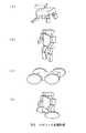
実際上、例えば胴体部ユニツトに対して頭部や、腕部、脚部及び車輪等の各種構成ユニツトを所望状態に取り付けることにより、例えば図9(A)のような4足歩行型や、図9(B)のような2足歩行型、図9(C)のような車型、又は図9(D)のような2輪推進型などの各種形態に組み立て得るようになされたロボツトでは、組み立て終わつた段階で全体の構成を自動的に認識できるように構築したとしても、当該ロボツトがどのユニツトを「腕」として用い、どのユニツトを「足」として用いるかといつたことや、2足歩行型及び4足歩行型のいずれの形態に組み立てられたのかといつたことを判別できず、組み立てた段階において直ちにその形態に応じた行動を行わせ難い問題がある。
【0008】
従つてこのような問題を解決しなければ、構築したロボツトの形態に応じたプログラムを入力するなどの作業を行うことなしに当該ロボツトに組立て形態に応じた行動をとらせることができず、モジユラ型ロボツトの組み立て作業を容易化させることができない。
【0009】
本発明は以上の点を考慮してなされたもので、組立て作業を容易化させ得るロボツト装置を提案しようとするものである。
【0010】
【課題を解決するための手段】
かかる課題を解決するため本発明においては、分離可能な複数の構成ユニツトを、2つ以上に分岐して連結された複数の構成ユニツトにより構築されるモジユラ型のロボツト装置において、各構成ユニツトの連結状態を検出する連結状態検出手段と、ロボツト装置の形態を各構成ユニツトの連結状態に応じて複数のカテゴリに分類した、各カテゴリ毎の各構成ユニツトの連結状態を記憶する記憶手段と、連結状態検出手段により検出された各構成ユニツトの連結状態と、記憶手段により記憶された各カテゴリ毎の各構成ユニツトの連結状態とに基づいて、ロボツト装置がどのカテゴリに属するかを判別する判別手段とを設けることにより、2つ以上に分岐して連結された複数の構成ユニツトの連結状態を基にモジユラ型のロボツト装置自身がそのカテゴリを判別することができるので、2つ以上に分岐して連結された複数の構成ユニツトからなる複雑な形態のロボツト装置であつても、ロボツト装置が組み立てられた段階で、ユーザがその形態を知らせることなく、その形態を認識してロボツト装置自身がカテゴリを把握することができる。
【0011】
この結果、ロボツト装置では、ユーザが構築したロボツト装置にその形態を知らせることなくロボツト装置に自分自身の形態を自動的に認識させることができる。
【0014】
【発明の実施の形態】
以下図面について、本発明の一実施の形態を詳述する。
【0015】
(1)第1の実施の形態
(1−1)第1の実施の形態によるロボツトの構成
図1において、1は全体として本発明によるモジユラ型のロボツトを示し、胴体部ユニツト2の前後左右の各隅部にそれぞれ太股部ユニツト3〜6及びすね部ユニツト7〜10が順次着脱自在に連結されると共に、胴体部ユニツト2の前端中央部に首部ユニツト11及び頭部ユニツト12が順次着脱自在に連結されている。なお以下の説明においては、胴体部ユニツト2、各太股部ユニツト3〜6、各すね部ユニツト7〜10、首部ユニツト11及び頭部ユニツト12をまとめて構成ユニツト2〜12と呼ぶものとする。
【0016】
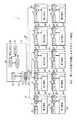
この場合胴体部ユニツト2の内部には、図2に示すように、ロボツト1全体の動作制御を司るCPU(Central Processing Unit )20、後述のシリアルバスを管理するSBH(Serial Bus Host )21、HUB(分配器)22、メモリ23、RAM(Random Access Memory)18及び構築されたロボツト1に各種行動を発生させるためのプログラムが格納されたROM(Read Only Memory)19が収納されている。
【0017】
またメモリ23には、胴体部ユニツト2の幅や長さ等の形状に関する情報(以下、これを形状情報と呼ぶ)と、胴体部ユニツト2の質量、回転モーメント、回転軸の中心位置及び当該胴体部ユニツト2の重心位置などの運動を記述するのに必要な情報(以下、これを運動情報と呼ぶ)と、HUB22の各連結点P1〜P5の位置情報とが格納されている。
【0018】
一方、胴体部ユニツト2を除く各構成ユニツト3〜12の内部には、それぞれHUB24と、メモリ25と、アクチユエータ及びセンサ等の必要な電子部品26とが収納されており、各メモリ25にはそれぞれその構成ユニツト3〜12の形状情報及び運動情報と、当該構成ユニツト3〜12に収納された電子部品26の機能及び特性に関する情報(以下、これを特性情報と呼ぶ)とが格納されている。
【0019】
さらに各構成ユニツト2〜12には、それぞれ他の構成ユニツト2〜12との連結位置に、その構成ユニツト2〜12の内部に配設されたIEEE1394又はUSB(Universal Serial Bus)等のシリアルバス27を介してHUB24と接続されたコネクタ(図示せず)が設けられており、構成ユニツト2〜12同士を物理的に連結することによつてこれら構成ユニツト2〜12内のHUB22、24同士をもシリアルバス27を介して電気的に接続し得るようになされている。
【0020】
これによりこのロボツト1においては、例えば図1及び図2のように組み立てられた状態において、胴体部ユニツト2内のCPU20が当該胴体部ユニツト2内のSBH21及びHUB22と各構成ユニツト3〜12内のHUB24とを順次介して、これら構成ユニツト2〜12内のメモリ23、25からその構成ユニツト2〜12の形状情報や運動情報及び特性情報を読み出し、若しくは各構成ユニツト3〜12内のセンサの出力を受信し、又は各構成ユニツト3〜12内のアクチユエータを制御することができるようになされている。
【0021】
かくするにつきこのロボツト1では、CPU20が、胴体部ユニツト2のメモリ23に格納されたHUB22の各連結点P1〜P5の位置情報と、各構成ユニツト2〜12のメモリ23、25にそれぞれ格納された形状情報とに基づいて、胴体部ユニツト2のどの連結位置にどのような構成ユニツト3〜6が連結され、またその構成ユニツト3〜6にどのような構成ユニツト7〜10が連結されているかといつたロボツト1の形態を認識できる。
【0022】
またこのロボツト1では、CPU20が、胴体部ユニツト2を除く各構成ユニツト3〜12のメモリ25にそれぞれ格納された運動情報及び電子部品26の特性情報に基づいて、各構成ユニツト3〜12のアクチユエータを所望状態に駆動し、かつそのときの各構成ユニツト3〜12の状態をその構成ユニツト3〜12内のセンサの出力に基づいてモニタし得るようになされている。
【0023】
かかる構成に加えこのロボツト1の場合、各構成ユニツト2〜12のメモリ23、25には、例えば「右前太股」や、「左後すね」、「首」、「頭」などといつたその構成ユニツト2〜12のロボツト1全体からみた役割に関する情報(以下、これを役割情報と呼ぶ)が格納されている。
【0024】
これによりこのロボツト1では、この役割情報に基づいてCPU20が各構成ユニツト2〜12の役割を認識でき、かくして例えば外部(又は内部の上位のプログラム)から「右前すね部を上げろ」といつた所定の役割の構成ユニツト2〜12を所定状態に駆動すべき動作命令が与えられたときに、対応する構成ユニツト2〜12のアクチユエータを制御することによつて指定された構成ユニツト2〜12を指定された状態に動作させ得るようになされている。
【0025】
ここで実際上CPU20は、ロボツト1が組み立てられた状態において電源が投入されると、ROM19に格納された各種行動を発生させるためのプログラムを読み出し、これをRAM18にダウンロードする。
【0026】
次いでCPU20は、胴体部ユニツト2内のSBH21及びHUB22と、各構成ユニツト3〜12内のHUB24とを順次介して各構成ユニツト2〜12内のメモリ23、25から当該メモリ23、25内に格納されたその構成ユニツト2〜12についての形状情報や運動情報、特性情報及び役割情報を読み出し、これらをRAM19に格納する一方、各構成ユニツト2〜12の形状情報に基づいて組み立てられたロボツト1の形態を認識し、各構成ユニツト2〜12の役割情報に基づいて各構成ユニツト2〜12の役割を認識する。
【0027】
またCPU20は、この後例えば外部から「右前すね部を上げろ」、「頭をさげろ」といつた所定の役割の構成ユニツト2〜12を所定状態に駆動すべき動作命令が与えられると、RAM18にダウンロードしたプログラムと、RAM18に格納された対応する構成ユニツト3〜12の運動情報及び特性情報とに基づいて対応する制御信号を生成し、当該生成した制御信号をその構成ユニツト3〜12内のアクチユエータに与える。
【0028】
このようにしてCPU20は、この制御信号に基づいて指定された構成ユニツト3〜12のアクチユエータを指定された状態に駆動させるようになされ、かくして当該構成ユニツト3〜12を指定された状態に駆動させるようになされている。
【0029】
(1−2)第1の実施の形態の動作及び効果
以上の構成において、このロボツト1では、CPU20が各構成ユニツト3〜12のメモリ25に格納された役割情報に基づいて各構成ユニツト3〜12の役割を認識し、認識結果に基づいて構成ユニツト3〜12のアクチユエータを駆動制御することにより、外部から与えられる動作命令に応じた動作を実行する。
【0030】
従つてこのロボツト20では、組み立てられた状態においてユーザが胴体部ユニツト2に連結した各構成ユニツト3〜12の役割を設定する(組み立て後、ユーザが各構成ユニツト3〜12の役割に関するデータをCPU20に与える)必要がなく、その分組み立て作業を簡易化させることができる。
【0031】
以上の構成によれば、各構成ユニツト3〜12にその構成ユニツト3〜12の役割情報を記録したメモリ24を配設すると共に、当該役割情報に基づいてCPU20が各構成ユニツト3〜12の役割を認識するようにしたことにより、ユーザが各構成ユニツト3〜12の役割を設定することなくCPU20に各構成ユニツト2〜12の役割を認識させることができ、かくして組み立て作業を容易化させ得るロボツトを実現できる。
【0032】
(2)第2の実施の形態
(2−1)第2の実施の形態によるロボツトの構成
図2との対応部分に同一符号を付して示す図3及び図1は、第2の実施の形態によるロボツト30を示し、胴体部ユニツト31のROM50に格納されたプログラムがROM19(図2)に格納されたプログラムと異なる点と、胴体部ユニツト31の内部に重力センサを含む電子部品51が追加されている点と、各構成ユニツト31〜41のメモリ54、52にその構成ユニツト31〜41の役割情報が格納されておらず、その構成ユニツト31〜41に関する形状情報、運動情報及び特性情報のみが格納されている点とを除いて第1の実施の形態のロボツト1(図1及び図2)とほぼ同様に構成されている。
【0033】
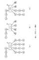
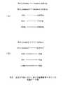
この場合この胴体部ユニツト31のROM50には、ロボツト30が組み立てられた状態において例えば図4(A)〜(C)のようにCPU53に対してアクチユエータAc や車輪Wh がどのような位置関係でどのような順番で接続されるかといつた、CPU53とアクチユエータAc 及び車輪Wh との接続関係を表すツリー構造のデータが格納されている。
【0034】
実際上ロボツト30の形態は、このようなツリー構造に応じて複数のカテゴリに分けることができ、例えば図9(A)及び(B)のような形態のロボツトではそのツリー構造が図4(A)のように表されるのに対して、図9(C)のような形態のロボツトではそのツリー構造が図4(B)のように表され、図9(D)のような形態のロボツトでは、そのツリー構造が図4(C)のように表される。
【0035】
そして胴体部ユニツト31のROM50には、予め予想される構築されるロボツト30の形態をそのツリー構造に応じて複数のカテゴリに分類した場合の各カテゴリ毎のツリー構造のデータが格納されている。なおこの場合、例えば図9(A)及び(B)のように同じツリー構造の形態でも、電源投入時におけるロボツト30の姿勢により異なるカテゴリに分類されている(胴体部ユニツト31が鉛直方向と平行に位置している場合は2足歩行型、胴体部ユニツト31が鉛直方向と垂直な方向に位置している場合は4足歩行型など)。
【0036】
またROM50には、これら各カテゴリのツリー構造のデータと共に例えばどの構成ユニツト32〜41を「頭」、「足」、「手」などと認識してどのように行動するかといつた行動を発生させるためのプログラムが各カテゴリにそれぞれ対応させて複数種類格納されている。
【0037】
これによりこのロボツト30においては、胴体部ユニツト31のCPU53が、各構成ユニツト31〜41のメモリ54、52内に格納された形状情報に基づいて組み立てられたロボツト30の形態を認識し、当該認識結果と、ROM50に格納された各カテゴリのツリー構造のデータとに基づいてそのロボツト30のカテゴリを判別でき、さらにこの判別結果と、ROM50に格納された各カテゴリ毎の行動のための各種プログラムに基づいて必要時に必要な構成ユニツト32〜41を駆動制御することにより、組立て形態に応じた行動をとることができるようになされている。
【0038】
ここで実際上、胴体部ユニツト31のCPU53は、ロボツト30が組み立てられた状態において電源が投入されると、ROM50に格納された各種プログラムを読み出し、これをRAM18にダウンロードする。
【0039】
次いでCPU53は、SBH21及びHAB22と、各構成ユニツト32〜41のHUB24とを順次介して各構成ユニツト31〜41のメモリ54、52から形状情報を読み出すことにより組み立てられたロボツト30のツリー構造を検出する。またこのときCPU53は、胴体部ユニツト31の電子部品51を構成する重力センサの出力に基づいて、電源投入時におけるロボツト30の姿勢を検出する。
【0040】
次いでCPU53は、このようにして検出したロボツト30のツリー構造及び姿勢に基づいてそのロボツトのカテゴリを判別し、当該判別結果に基づいて対応するプログラムを選択し、当該プログラムに基づいてそのカテゴリにおける基本姿勢を各状態ごとに割り付ける。実際上例えば4足型ロボツトであれば胴体部ユニツト31を水平にすると共に各足を伸ばした状態が「standing」の基本姿勢として割り付けられ、2輪推進型であれば胴体部ユニツト31を垂直にした状態が「standing」の基本姿勢として割り付けられる。そしてCPU53は、この後このプログラム基づいて必要時に必要な構成ユニツト32〜41内のアクチユエータを制御する。
【0041】
このようにしてCPU53は、組み立てられたロボツト30の形態及び電源投入時における姿勢に基づいて、対応するプログラムに従つて各構成ユニツト32〜41を駆動制御する。
【0042】
(2−2)第2の実施の形態におけるソフトウエアのアーキテクチヤ
ここで図5は、胴体部ユニツト31のROM50に格納されるソフトウエアのアーキテクチヤを示すものである。
【0043】
この図5においてCPC(Configurational Physical Component)ドライバ60は各構成ユニツト32〜41のアクチユエータ等のCPCデバイスを初期化したり、胴体部ユニツト31のRAM18にデータを読み書きするプログラムであり、CPU53により検出された現在のロボツト30のツリー構造のデータ及び電源投入時におけるロボツト30の姿勢に関するデータ(以下これらデータをまとめて形態データD1と呼ぶ)を保持する。そしてこの形態データD1がカテゴリーストツク61に与えられる。
【0044】
カテゴリストツク61は、予め登録された各カテゴリ毎のツリー構造のデータ及び姿勢のデータ(以下、これらデータをまとめてカテゴリ分けデータCD1〜CDnと呼ぶ)を管理するプログラムであり、これら登録された各カテゴリ分けデータCD1〜CDnと、CPCドライバ60から与えられる形態データD1とを比較することにより、組み立てられたロボツト30がどのカテゴリに属するかを判別し、判別結果をカテゴリーインフオメーシヨンストツク62に与える。
【0045】
カテゴリーインフオメーシヨンストツク62は、予め登録されている各カテゴリでのロボツト30の姿勢遷移と動きに関するプログラム(以下、これをモーシヨンネツトワークと呼ぶ)MoNet1〜MoNetnと、各カテゴリにおいて上位のプログラムから与えられる行動コマンドCOM を対応する命令に変換するための変換データCC1〜CCnとを管理するプログラムであり、カテゴリーストツク61による判別結果に基づいて対応するモーシヨンネツトワークMoNet1〜MoNetn及び変換データCC1〜CCnを選択し、これをモーシヨンジエネレータ63に与える。
【0046】
モーシヨンジエネレータ63は、動作データを生成するプログラムであり、カテゴリーインフオメーシヨンストツク62から与えられるモーシヨンネツトワークMoNet1〜MoNetn及び変換データCC1〜CCnを保持する一方、当該保持した変換データCC1〜CCnに基づいて上位のプログラムから与えられる行動コマンドCOM をそのカテゴリに応じた命令に変換し、得られた命令と、保持しているモーシヨンネツトワークMoNet1〜MoNetnとに基づいて対応する動作データD2を生成し、これをCPCドライバ60に与える。
【0047】
かくしてロボツト30においては、このCPCドライバ60に従つてCPU53の制御のもとに各構成ブロツク32〜41内の対応するアクチユエータが制御され、これにより上位のプログラムから与えられる行動コマンドCOM 応じた行動が行われる。
【0048】
なお図6に4足歩行型ロボツトのモーシヨンネツトワークMoNetxのグラフ構造を示し、図7に2輪推進型ロボツトのモーシヨンネツトワークMoNetyのグラフ構造を示す。
【0049】
図6からも明らかなように、4足歩行型ロボツトのモーシヨンネツトワークMoNetxは、「sleeping」、「sitting 」、「standing」、「forward walking 」及び「forward walking 」の5つのNodeST1〜ST5を有し、これらのうちの遷移可能なNodeST1〜ST5間がEdge(向きつきの矢)により結ばれている。
【0050】
また各NodeST1〜ST5にはそのNodeST1〜ST5での動作を発生させるためのプログラムE1〜E5が関連付けられると共に、各Edgeにもその状態遷移の際に必要とする動作を発生させるためのプログラムE6〜E13が関連付けられている。この状態遷移の際に必要とする動作を発生させるためのプログラムE6〜E13は制御アルゴリズムを含むプログラムであり、各状態遷移の際に必要となる制御はここから供給される。
【0051】
なお2輪推進型ロボツトのモーシヨンネツトワークMoNety(図7)も、「sleeping」及び「sitting 」のNodeST1、ST2がないことを除いて4足歩行型ロボツトのモーシヨンネツトワークMoNetxとほぼ同様に構成される。
【0052】
さらに図8は、4足歩行型ロボツト及び2輪推進型ロボツトの各変換データCCx、CCYを示すものである。この図8からも明らかなように、4足歩行型ロボツトでは、上位のプログラムから与えられる「Move forward」、「Move backward 」、「stay」、「Rest」及び「sleep 」といつた命令がそれぞれ「forward walking 」、「backward walking」、「standing」、「sitting 」又は「sleeping」といつた命令に変換される。
【0053】
また2輪推進型ロボツトでは、「Move forward」、「Move backward 」、「stay」、「Rest」及び「sleep 」といつた命令がそれぞれ「forward 」、「backward」、「stop」、「stop」又は「stop」といつた命令に変換される。
【0054】
(2−3)第2の実施の形態の動作及び効果
以上の構成において、胴体部ユニツト31のCPU53は、各構成ユニツト31〜41のメモリ54、52内に格納された形状情報に基づいて組み立てられたロボツト30の形態を認識し、当該認識結果と、ROM50に格納された各カテゴリのツリー構造のデータとに基づいてそのロボツト30のカテゴリを判別し、さらにこの判別結果と、ROM50に格納された各カテゴリ毎の行動のための各種プログラムに基づいて各構成ユニツト32〜41のアクチユエータを駆動制御することにより、ロボツト30全体として組立て形態に応じた行動を実行させる。
【0055】
従つてこのロボツト30では、組み立てられた状態においてユーザがそのロボツト30の組立て形態をCPU53に知らせることなくロボツト30自身が電源投入時に自分の形態を認識することができ、その分組み立て作業を簡易化させることができる。
【0056】
またこのロボツト30の場合、例えば第1の実施の形態のように各構成ユニツト31〜41のメモリに役割情報が格納されていない分、各構成ユニツト31〜41を予め設定した役割以外の役割をもたせて使用する(例えば「足」としてして用いていた構成ユニツト32〜39を例えば指の1本として使用する)ことができるため、第1の実施の形態に比べて各構成ユニツト31〜41の汎用性を向上させることができる。
【0057】
以上の構成において、CPU53が、各構成ユニツト31〜41のメモリ54、52内に格納された形状情報に基づいて組み立てられたロボツト30の形態を認識し、当該認識結果と、ROM50に格納された各カテゴリのツリー構造のデータとに基づいてそのロボツト30のカテゴリを判別し、さらにこの判別結果と、ROM50に格納された各カテゴリ毎の行動のための各種プログラムに基づいて必要時に必要な構成ユニツト32〜41のアクチユエータを駆動制御するようにしたことにより、ロボツト30に自分自身の形態を自動的に認識させ、これに応じた行動をとらせることができ、かくして組み立て作業を容易化させ得るロボツトを実現できる。
【0058】
(3)他の実施の形態
なお上述の第1の実施の形態においては、各構成ユニツト2〜12にそれぞれ設けられ、その構成ユニツト2〜12の役割に関する役割情報を記憶する記憶手段として、メモリ23、25を適用するようにした場合について述べたが、本発明はこれに限らず、デイスク状記録媒体や、テープ状記録媒体などこの他種々の記憶手段を広く適用することができる。
【0059】
また上述の第1の実施の形態においては、各構成ユニツト2〜12のメモリ23、25からその構成ユニツト2〜12の役割情報をそれぞれ読み出し、当該読み出した各役割情報に基づいて各構成ユニツト2〜12の役割を認識する認識手段としてロボツト1全体の制御を司るCPU20を適用するようにした場合について述べたが、本発明はこれに限らず、各構成ユニツト2〜12の役割を認識する認識手段と、ロボツト1全体の制御を司るCPU20とを別体に構成するようにしても良く、認識手段の構成としては、この他種々の構成を広く適用することができる。
【0060】
さらに上述の第1の実施の形態においては、各種行動を発生させるためのプログラムを胴体部ユニツト2のROM19に格納しておくようにした場合について述べたが、本発明はこれに限らず、例えば外部からその役割の構成ユニツトを所定状態に動かすべき動作命令が与えられた場合の対応する動作を発生させるためのプログラムを各構成ユニツト2〜12のメモリ23、25に格納しておき、CPU20が電源投入時又はこの他のタイミングでこのプログラムを読み出し、当該読み出したプログラムと、各構成ユニツト2〜12の役割の認識結果とに基づいて、所定の役割の構成ユニツト2〜12を所定状態に駆動すべき動作命令が与えられたときに対応する構成ユニツト2〜12を駆動制御するための制御信号を生成し、当該制御信号に基づいて対応する構成ユニツト2〜12内のアクチユエータを駆動制御するようにしても良い。
【0061】
さらに上述の第1の実施の形態においては、CPU20が各構成ユニツト2〜12の形状情報に基づいて組み立てられたロボツト1の形態を認識するようにした場合について述べたが、その手法として例えば第2の実施の形態のように組み立てられたロボツト1のツリー構造に応じてその形態を認識するようにすれば良い。
【0062】
さらに上述の第2の実施の形態においては、各構成ユニツト31〜41の連結状態(ツリー構造)を検出する連結状態検出手段として、ロボツト30全体の制御を司るCPU53を適用するようにした場合について述べたが、本発明はこれに限らず、連結状態検出手段をロボツト30全体の制御を司るCPU53と別体に設けるようにしても良い。
【0063】
さらに上述の第2の実施の形態においては、構築されるロボツト装置の形態を各構成ユニツト31〜41の連結状態に応じて複数のカテゴリに分類した、各カテゴリ毎の各構成ユニツト31〜41の連結状態を記憶する記憶手段としてROM50を適用するようにした場合について述べたが、本発明はこれに限らず、記憶手段としては、デイスク状記録媒体やテープ状記録媒体等この他種々の記憶手段を広く適用することができる。
【0064】
さらに上述の第2の実施の形態においては、検出した各構成ユニツト31〜41の連結状態と、予めROM50に格納されている各カテゴリ毎の各構成ユニツト31〜41の連結状態とに基づいて、構築されたロボツト30がどのカテゴリに属するかを判別する判別手段として、ロボツト30全体の制御を司るCPU53を適用するようにした場合について述べたが、本発明はこれに限らず、判別手段をロボツト30全体の制御を司るCPU53と別体に設けるようにしても良い。
【0065】
さらに上述の第2の実施の形態においては、構築されるロボツト30の形態を初期状態と、ツリー構造とに応じてカテゴリ分けするようにした場合について述べたが、本発明はこれに限らず、要は、構築されるロボツト30の形態を少なくともツリー構造によりカテゴリ分けするのであれば、これ以上の細かなカテゴリ分けの方法としてはこの他種々の方法を広く適用することができる。
【0066】
さらに上述の第2の実施の形態においては、胴体部ユニツト31内に重力センサを配設し、当該重力センサの出力に基づいてCPU53がロボツト30の形態のカテゴリを判別するようにした場合について述べたが、本発明はこれに限らず、例えば構築されたロボツトの形態の種類(2足歩行型、4足歩行型、車輪型、2輪推進型など)を入力設定できるスイツチ等の設定手段をロボツト30に設け、ユーザによる当該設定手段を介した入力設定に基づいてCPU53がロボツト30の形態のカテゴリを判別するようにしても良い。
【0067】
また重力センサに代えて例えば各構成ユニツト31〜41に接地センサを設け、当該接地センサの出力に基づいて初期状態においてどの構成ユニツト31〜41のどの部分が接地しているかに基づいて構築されたロボツト31の形態のカテゴリを判別するようにしても良く、初期状態を判別し得るようにする手法としては、この他種々の手法を広く適用することができる。
【0068】
さらに上述の第2の実施の形態においては、CPU53が電源投入時におけるロボツト30の姿勢に基づいて当該ロボツト30のカテゴリを判別するようにした場合について述べたが、本発明はこれに限らず、CPU53が電源投入時以外の他のタイミング時におけるロボツト30の姿勢に基づいて当該ロボツト30のカテゴリを判別するようにしても良い。
【0069】
【発明の効果】
上述のように本発明によれば、2つ以上に分岐して連結された複数の構成ユニツトの連結状態を基にモジユラ型のロボツト装置自身がそのカテゴリを判別することができるので、2つ以上に分岐して連結された複数の構成ユニツトからなる複雑な形態のロボツト装置であつても、ロボツト装置が組み立てられた段階で、ユーザがその形態を知らせることなく、その形態を認識してロボツト装置自身がカテゴリを把握することができ、かくして組立て作業を容易化させ得るロボツト装置を実現することができる。
【図面の簡単な説明】
【図1】本発明によるロボツトの構成を示す概念図である。
【図2】第1の実施の形態によるロボツトの構成を示すブロツク図である。
【図3】第2の実施の形態によるロボツトの構成を示すブロツク図である。
【図4】各種ツリー構造を示す概念図である。
【図5】第2の実施の形態によるソフトウエアのアーキテクチヤを示す概念図である。
【図6】4足歩行型ロボツトのモーシヨンネツトワークを示す概念図である。
【図7】2輪推進型ロボツトのモーシヨンネツトワークを示す概念図である。
【図8】4足歩行型ロボツト及び2輪推進型ロボツトにおけるそれぞれの変換データ例を示す図表である。
【図9】モジユラ型ロボツトの各種形態の説明に供する略線的な斜視図である。
【符号の説明】
1、30……ロボツト、2〜12、31〜31……構成ユニツト、19、50……ROM、20、53……CPU、23、25、52……メモリ。[0001]
【table of contents】
The present invention will be described in the following order.
[0002]
TECHNICAL FIELD OF THE INVENTION
Conventional technology (Fig. 9)
Problems to be Solved by the Invention (FIG. 9)
Means for Solving the Problems (FIGS. 1 to 8)
BEST MODE FOR CARRYING OUT THE INVENTION
(1) First embodiment
(1-1) Configuration of the robot according to the first embodiment (FIGS. 1 and 2)
(1-2) Operation and effect of the first embodiment (FIGS. 1 and 2)
(2) Second embodiment
(2-1) Configuration of the robot according to the second embodiment (FIG. 3)
(2-2) Software architecture in the second embodiment (FIGS. 4 to 8)
(2-3) Operation and effect of the second embodiment (FIGS. 3 to 8)
(3) Other embodiments (FIGS. 1 to 8)
The invention's effect
[0003]
BACKGROUND OF THE INVENTION
The present invention relates to a robot apparatus, and is suitable for application to a so-called modular robot constructed by connecting a plurality of constituent units (parts), for example.
[0004]
[Prior art]
Conventionally, as this type of robot, for example, JP-A-47-25858, JP-A-59-205292, “Robot Models for Space Environment” (ROAmbrose and CGAmbrose, IEEE International conference on R & A, 1995 pp.2113). -2131), “The Concept and Construction of a modular robot system” (K.-H Wurst Proc of 16th ISIR, 1986, pp.37-44) and "Conceptual Design of a Modular Robot" (R. Cohen et.al Journal of Mechanical Design, 1992 vol.114 pp.117-125) etc. Has been.
[0005]
In addition, for example, “Examination of Modular Manupulator Configuration / Shape Recognition and Work Performance Determination Method” (Takafumi Matsumaru et al. Journal of the Robotics Society of Japan Vol.15 No.3, PP.408 to 416.1997) links to joint modules. A method for automatically recognizing the configuration of a modular manipulator that can be constructed by freely connecting modules and making it possible to perform practical and useful work immediately after assembly is disclosed.
[0006]
[Problems to be solved by the invention]
However, these are all based on the premise of a manipulator (arm of a machine). For this reason, there is a problem that it is difficult to apply the various devices disclosed in these documents to a robot of a type in which two or more constituent units are branched and connected. It was.
[0007]
In practice, for example, by attaching various components such as the head, arms, legs and wheels to the body unit in a desired state, for example, a quadruped walking type as shown in FIG. In a robot that can be assembled in various forms such as a biped walking type such as 9B, a vehicle type such as FIG. 9C, or a two-wheel propulsion type such as FIG. Even if it is constructed so that the entire configuration can be recognized automatically at the end stage, the robot uses which unit as an “arm” and which unit is used as a “foot”, and the biped walking type In addition, there is a problem that it is difficult to determine when it is assembled in any form of the quadruped walking type and when it is assembled, and it is difficult to immediately perform an action according to the form in the assembled stage.
[0008]
Therefore, if such a problem is not solved, the robot cannot take action according to the assembly form without performing a work such as inputting a program according to the form of the constructed robot. The assembly work of the type robot cannot be facilitated.
[0009]
The present invention has been made in consideration of the above points, and an object of the present invention is to propose a robot apparatus capable of facilitating assembly work.
[0010]
[Means for Solving the Problems]
In order to solve such a problem, in the present invention, in a modular type robot apparatus constructed by a plurality of constituent units branched and connected to a plurality of separable constituent units, the constituent units are connected. Connected state detecting means for detecting the state, storage means for classifying the form of the robot device into a plurality of categories according to the connected state of each constituent unit, storing means for connecting the connected state of each constituent unit for each category, and connected state Discriminating means for discriminating which category the robot apparatus belongs to based on the connected state of each constituent unit detected by the detecting means and the connected state of each constituent unit for each category stored by the storing means. By providing, the modular robot device itself is based on the connection state of a plurality of constituent units branched and connected to two or more. Therefore, even if the robot apparatus has a complicated form composed of a plurality of constituent units branched and connected to two or more categories, the user can change the form of the robot apparatus when the robot apparatus is assembled. The robot apparatus itself can recognize the category without recognizing the category.
[0011]
As a result, in the robot apparatus, the robot apparatus can automatically recognize its own form without informing the robot apparatus constructed by the user of the form.
[0014]
DETAILED DESCRIPTION OF THE INVENTION
Hereinafter, an embodiment of the present invention will be described in detail with reference to the drawings.
[0015]
(1) First embodiment
(1-1) Configuration of the robot according to the first embodiment
In FIG. 1, 1 is a modular type robot according to the present invention as a whole, and a crotch unit 3-6 and a shin unit 7-10 are detachably connected to the front, rear, left and right corners of the
[0016]
In this case, as shown in FIG. 2, the
[0017]
The
[0018]
On the other hand, in each of the
[0019]
Further, each of the
[0020]
Thus, in the
[0021]
Accordingly, in this
[0022]
In the
[0023]
In addition to such a configuration, in the case of this
[0024]
As a result, in this
[0025]
Here, in practice, when the power is turned on in a state where the
[0026]
Next, the
[0027]
When the
[0028]
In this way, the
[0029]
(1-2) Operation and effect of the first embodiment
In the above configuration, in the
[0030]
Therefore, in this
[0031]
According to the above configuration, the
[0032]
(2) Second embodiment
(2-1) Configuration of the robot according to the second embodiment
3 and 1 in which parts corresponding to those in FIG. 2 are assigned the same reference numerals show a
[0033]
In this case, in the
[0034]
Actually, the form of the
[0035]
The
[0036]
In addition, the
[0037]
Thereby, in this
[0038]
Here, in practice, the
[0039]
Next, the
[0040]
Next, the
[0041]
In this way, the
[0042]
(2-2) Software architecture in the second embodiment
Here, FIG. 5 shows a software architecture stored in the
[0043]
In FIG. 5, a CPC (Configurational Physical Component)
[0044]
The category stock 61 includes tree structure data and attitude data (hereinafter these data are grouped into categorized data CD).1 ~ CDn Each of these registered categorized data CDs.1 ~ CDn And the form data D1 provided from the
[0045]
The category information stock 62 is a program related to the posture transition and movement of the
[0046]
The
[0047]
Thus, in the
[0048]
Figure 6 shows a four-legged walking robot Monet network MoNet.x Fig. 7 shows the structure of a two-wheel propulsion type robot Monet network MoNet.y The graph structure of is shown.
[0049]
As is clear from FIG. 6, the movement network MoNet of a four-legged walking robotx Has five Nodes ST1 to ST5 of “sleeping”, “sitting”, “standing”, “forward walking”, and “forward walking”, and among these transitionable Nodes ST1 to ST5, there is an Edge (direction arrow). ).
[0050]
Further, each of the Nodes ST1 to ST5 is associated with programs E1 to E5 for generating operations in the Nodes ST1 to ST5, and each Edge also has programs E6 to E for generating operations necessary for the state transition. E13 is associated. Programs E6 to E13 for generating operations necessary for the state transition are programs including a control algorithm, and control necessary for each state transition is supplied from here.
[0051]
Two-wheel-propelled robot Monet network MoNety (Fig. 7) is also a four-legged robot movement network MoNet except that there are no "sleeping" and "sitting" Nodes ST1 and ST2.x The configuration is almost the same.
[0052]
Further, FIG. 8 shows conversion data CC of a quadruped robot and a two-wheel propulsion robot.x , CCY Is shown. As is apparent from FIG. 8, in the quadruped walking robot, the instructions given by the upper program “Move forward”, “Move backward”, “stay”, “Rest” and “sleep” “Forward walking”, “backward walking”, “standing”, “sitting” or “sleeping” is converted into a command.
[0053]
In the two-wheel propulsion robot, the commands “Move forward”, “Move backward”, “stay”, “Rest” and “sleep” are “forward”, “backward”, “stop”, “stop”, respectively. Or, it is converted into a command that is “stop”.
[0054]
(2-3) Operation and effect of the second embodiment
In the above configuration, the
[0055]
Therefore, in the
[0056]
In the case of this
[0057]
In the above configuration, the
[0058]
(3) Other embodiments
In the first embodiment described above, the
[0059]
In the first embodiment described above, the role information of the
[0060]
Furthermore, in the above-described first embodiment, the case where the program for generating various actions is stored in the
[0061]
Furthermore, in the above-described first embodiment, the case where the
[0062]
Further, in the second embodiment described above, the
[0063]
Furthermore, in the above-described second embodiment, the form of the robot apparatus to be constructed is classified into a plurality of categories according to the connection state of each of the
[0064]
Furthermore, in the above-described second embodiment, based on the detected connection state of each component unit 31-41 and the connection state of each component unit 31-41 for each category stored in advance in the
[0065]
Furthermore, in the above-described second embodiment, the case where the form of the
[0066]
Further, in the second embodiment described above, a case where a gravity sensor is provided in the
[0067]
Further, instead of the gravity sensor, for example, a ground sensor is provided in each of the
[0068]
Furthermore, in the above-described second embodiment, the case where the
[0069]
【The invention's effect】
As described above, according to the present invention, the modular robot device itself can determine the category based on the connection state of a plurality of constituent units that are branched and connected to two or more. Even if the robot device has a complicated configuration consisting of a plurality of constituent units branched and connected to each other, the robot device recognizes the configuration and notifies the robot device at the stage when the robot device is assembled. It is possible to realize a robot apparatus that can grasp the category by itself and thus facilitate the assembling work.
[Brief description of the drawings]
FIG. 1 is a conceptual diagram showing a configuration of a robot according to the present invention.
FIG. 2 is a block diagram showing a configuration of a robot according to the first embodiment.
FIG. 3 is a block diagram showing a configuration of a robot according to a second embodiment.
FIG. 4 is a conceptual diagram showing various tree structures.
FIG. 5 is a conceptual diagram showing a software architecture according to a second embodiment;
FIG. 6 is a conceptual diagram showing a motion network of a quadruped walking robot.
FIG. 7 is a conceptual diagram showing a motion network of a two-wheel propulsion robot.
FIG. 8 is a chart showing conversion data examples of a quadruped robot and a two-wheel propulsion robot.
FIG. 9 is a schematic perspective view for explaining various forms of the modular robot.
[Explanation of symbols]
1, 30... Robot, 2-12, 31-31... Configuration unit, 19, 50... ROM, 20, 53.
Claims (3)
Translated fromJapanese各構成ユニツトの連結状態を検出する連結状態検出手段と、
上記ロボツト装置の形態を各上記構成ユニツトの上記連結状態に応じて複数のカテゴリに分類した、各上記カテゴリ毎の各上記構成ユニツトの上記連結状態を記憶する記憶手段と、
上記連結状態検出手段により検出された各上記構成ユニツトの上記連結状態と、上記記憶手段により記憶された各上記カテゴリ毎の各上記構成ユニツトの上記連結状態とに基づいて、上記ロボツト装置がどの上記カテゴリに属するかを判別する判別手段と
を具えることを特徴とするロボツト装置。In a modular type robot apparatusconstructed by a plurality of constituent units branched and connected to two or more separable constituent units,
A connection state detecting means for detecting a connection state of each component unit;
Were classified into several categories according to the form of theupper Symbol robot apparatus to the connection state of each said component units, a storage means for storing the connection states of the above component units for each said category,
And the connection state of each said component units detected by the connecting state detection means, based on the above connection state of each said component units in each said category stored by the storage means,the upper Symbol robot apparatus which And a discriminating means for discriminating whether the robot belongs to the category.
上記判別手段は、上記ロボツト装置がどの上記カテゴリに属するかの判別結果と、上記記憶手段に記憶された対応する上記プログラムとに基づいて各上記構成ユニツトを駆動制御するための制御信号を生成する
ことを特徴とする請求項1に記載のロボツト装置。The storage means stores a plurality of programs for generating basic operations for each of the categories,
The discriminating means generates a control signal for driving and controlling each of the constituent units based on the discriminating result of the category to which the robot apparatus belongs and the corresponding program stored in the storage means. The robot apparatus according to claim1 , wherein:
上記ロボツト装置の形態は、各上記構成ユニツトの上記連結状態及び電源投入時における当該ロボツト装置の姿勢に応じて複数の上記カテゴリに分類され、
上記判別手段は、上記重力センサの検出結果と、上記記憶手段により記憶された各上記カテゴリ毎の各上記構成ユニツトの上記連結状態とに基づいて、上記ロボツト装置がどの上記カテゴリに属するかを判別する
ことを特徴とする請求項1に記載のロボツト装置。It has a gravity sensor that detects the direction of gravity,
Form of the upperkilometers Botsuto device is classified into a plurality of the categories in accordance with the attitude of the robot apparatus during the connected state and the power-on of each said component units,
The discriminating unit discriminates to which category the robot device belongs based on the detection result of the gravity sensor and the connection state of each component unit for each category stored by the storage unit. The robot apparatus according to claim1 , wherein:
Priority Applications (13)
| Application Number | Priority Date | Filing Date | Title |
|---|---|---|---|
| JP34584197AJP3919040B2 (en) | 1997-11-30 | 1997-11-30 | Robot equipment |
| TW087119286ATW378286B (en) | 1997-11-30 | 1998-11-20 | Robot device |
| US09/197,332US6411055B1 (en) | 1997-11-30 | 1998-11-20 | Robot system |
| SG9804897ASG97125A1 (en) | 1997-11-30 | 1998-11-23 | Robot system |
| CA002254502ACA2254502C (en) | 1997-11-30 | 1998-11-25 | Robot system |
| ES98309707TES2196504T3 (en) | 1997-11-30 | 1998-11-26 | ROBOT SYSTEMS AND METHODS TO CONTROL THE OPERATION OF ROBOTS. |
| EP98309707AEP0923011B1 (en) | 1997-11-30 | 1998-11-26 | Robot systems and robot drive-controlling methods |
| DE69812558TDE69812558T2 (en) | 1997-11-30 | 1998-11-26 | Robot system and method for driving a robot |
| AU94203/98AAU755446B2 (en) | 1997-11-30 | 1998-11-27 | Robot system |
| BRPI9804751-5ABR9804751B1 (en) | 1997-11-30 | 1998-11-27 | robotic system and robot drive control process. |
| MYPI98005409AMY120352A (en) | 1997-11-30 | 1998-11-30 | Robot systems and robot drive-controlling methods. |
| CN98126901ACN1096919C (en) | 1997-11-30 | 1998-11-30 | Robot system |
| KR1019980051672AKR100549971B1 (en) | 1997-11-30 | 1998-11-30 | Robot device and its driving control method |
Applications Claiming Priority (1)
| Application Number | Priority Date | Filing Date | Title |
|---|---|---|---|
| JP34584197AJP3919040B2 (en) | 1997-11-30 | 1997-11-30 | Robot equipment |
Publications (2)
| Publication Number | Publication Date |
|---|---|
| JPH11156765A JPH11156765A (en) | 1999-06-15 |
| JP3919040B2true JP3919040B2 (en) | 2007-05-23 |
Family
ID=18379356
Family Applications (1)
| Application Number | Title | Priority Date | Filing Date |
|---|---|---|---|
| JP34584197AExpired - LifetimeJP3919040B2 (en) | 1997-11-30 | 1997-11-30 | Robot equipment |
Country Status (13)
| Country | Link |
|---|---|
| US (1) | US6411055B1 (en) |
| EP (1) | EP0923011B1 (en) |
| JP (1) | JP3919040B2 (en) |
| KR (1) | KR100549971B1 (en) |
| CN (1) | CN1096919C (en) |
| AU (1) | AU755446B2 (en) |
| BR (1) | BR9804751B1 (en) |
| CA (1) | CA2254502C (en) |
| DE (1) | DE69812558T2 (en) |
| ES (1) | ES2196504T3 (en) |
| MY (1) | MY120352A (en) |
| SG (1) | SG97125A1 (en) |
| TW (1) | TW378286B (en) |
Cited By (1)
| Publication number | Priority date | Publication date | Assignee | Title |
|---|---|---|---|---|
| US20240169292A1 (en)* | 2021-06-24 | 2024-05-23 | Workdone, Inc. | System of intelligence learning agents leveraging expertise capture for work heuristics management |
Families Citing this family (103)
| Publication number | Priority date | Publication date | Assignee | Title |
|---|---|---|---|---|
| JP2001038663A (en)* | 1999-07-28 | 2001-02-13 | Yamaha Motor Co Ltd | Machine control system |
| JP2001191284A (en)* | 1999-10-25 | 2001-07-17 | Sony Corp | Robot device and its learning method |
| USD457203S1 (en) | 1999-11-02 | 2002-05-14 | Sega Toys, Ltd. | Robotic dog |
| US7442107B1 (en) | 1999-11-02 | 2008-10-28 | Sega Toys Ltd. | Electronic toy, control method thereof, and storage medium |
| US6462498B1 (en) | 2000-05-09 | 2002-10-08 | Andrew J. Filo | Self-stabilizing walking apparatus that is capable of being reprogrammed or puppeteered |
| JP2002113675A (en)* | 2000-10-11 | 2002-04-16 | Sony Corp | Robot control system and introducing method for robot controlling software |
| US6705917B2 (en) | 2000-12-15 | 2004-03-16 | Andrew S. Filo | Self-phase synchronized walking and turning quadruped apparatus |
| US6454624B1 (en) | 2001-08-24 | 2002-09-24 | Xerox Corporation | Robotic toy with posable joints |
| US6575802B2 (en) | 2001-08-24 | 2003-06-10 | Xerox Corporation | Robotic toy modular system with distributed program |
| WO2003045639A2 (en) | 2001-11-28 | 2003-06-05 | Evolution Robotics, Inc. | Sensor and actuator abstraction and aggregation in a hardware abstraction layer for a robot |
| EP1484134B1 (en)* | 2002-02-15 | 2019-05-01 | Sony Corporation | Leg device for leg type movable robot, and method of controlling leg type movable robot |
| JP2003308221A (en)* | 2002-04-12 | 2003-10-31 | Nec Corp | System, method and program for robot control |
| US20040162637A1 (en) | 2002-07-25 | 2004-08-19 | Yulun Wang | Medical tele-robotic system with a master remote station with an arbitrator |
| JP4588993B2 (en)* | 2003-12-01 | 2010-12-01 | 川田工業株式会社 | Modular structure of walking robot |
| KR20070003811A (en)* | 2003-12-01 | 2007-01-05 | 뉴사우스 이노베이션즈 피티와이 리미티드 | Method for controlling a system formed of interdependent units |
| US7813836B2 (en) | 2003-12-09 | 2010-10-12 | Intouch Technologies, Inc. | Protocol for a remotely controlled videoconferencing robot |
| US7747352B2 (en)* | 2004-04-20 | 2010-06-29 | Massachusetts Institute Of Technology | Physical modeling system for constructing and controlling articulated forms with motorized joints |
| JP4713846B2 (en)* | 2004-04-30 | 2011-06-29 | 独立行政法人科学技術振興機構 | Robot remote control system |
| US8077963B2 (en) | 2004-07-13 | 2011-12-13 | Yulun Wang | Mobile robot with a head-based movement mapping scheme |
| JP2007038326A (en)* | 2005-08-01 | 2007-02-15 | Toyota Motor Corp | Robot control system |
| JP2007061965A (en)* | 2005-08-31 | 2007-03-15 | Victor Co Of Japan Ltd | Starting mode setting method in robot device |
| US7844396B2 (en)* | 2005-09-13 | 2010-11-30 | Deere & Company | Method and system for modular data processing for a vehicle control system |
| US9198728B2 (en) | 2005-09-30 | 2015-12-01 | Intouch Technologies, Inc. | Multi-camera mobile teleconferencing platform |
| CN101326034A (en)* | 2006-03-24 | 2008-12-17 | 松下电器产业株式会社 | Manipulator control method and control system |
| US8849679B2 (en) | 2006-06-15 | 2014-09-30 | Intouch Technologies, Inc. | Remote controlled robot system that provides medical images |
| JP2008006518A (en)* | 2006-06-27 | 2008-01-17 | Toyota Motor Corp | Robot control system, robot control method, and robot |
| US20080046121A1 (en)* | 2006-08-17 | 2008-02-21 | Innovati, Inc. | Developing system of re-configurable modularized robot |
| ATE473907T1 (en)* | 2006-11-13 | 2010-07-15 | Raytheon Sarcos Llc | VERSATILE ENDLESS BELT FOR LIGHTWEIGHT MOBILE ROBOTS |
| EP2549165B1 (en)* | 2006-11-13 | 2014-03-12 | Raytheon Company | Serpentine robotic crawler |
| ATE504486T1 (en) | 2006-11-13 | 2011-04-15 | Raytheon Co | ADJUSTABLE TRACK ARRANGEMENT FOR A TRACKER ROBOT |
| WO2008076193A2 (en) | 2006-11-13 | 2008-06-26 | Raytheon Sarcos Llc | Tracked robotic crawler having a moveable arm |
| EP2117782B1 (en)* | 2007-01-12 | 2014-07-30 | Hansjorg Baltes | Method and system for robot generation |
| DE102007005330A1 (en)* | 2007-01-29 | 2008-07-31 | Schunk Gmbh & Co. Kg Spann- Und Greiftechnik | Electric motor system and kit for this |
| WO2008137953A1 (en) | 2007-05-07 | 2008-11-13 | Raytheon Sarcos, Llc | Method for manufacturing a complex structure |
| US9160783B2 (en) | 2007-05-09 | 2015-10-13 | Intouch Technologies, Inc. | Robot system that operates through a network firewall |
| US8571711B2 (en) | 2007-07-10 | 2013-10-29 | Raytheon Company | Modular robotic crawler |
| KR100903667B1 (en)* | 2007-08-02 | 2009-06-18 | (주)로보티즈 | Robot Contents Trading System and Method Based on Network |
| US10875182B2 (en) | 2008-03-20 | 2020-12-29 | Teladoc Health, Inc. | Remote presence system mounted to operating room hardware |
| US8179418B2 (en) | 2008-04-14 | 2012-05-15 | Intouch Technologies, Inc. | Robotic based health care system |
| US8170241B2 (en) | 2008-04-17 | 2012-05-01 | Intouch Technologies, Inc. | Mobile tele-presence system with a microphone system |
| US9193065B2 (en) | 2008-07-10 | 2015-11-24 | Intouch Technologies, Inc. | Docking system for a tele-presence robot |
| US9842192B2 (en) | 2008-07-11 | 2017-12-12 | Intouch Technologies, Inc. | Tele-presence robot system with multi-cast features |
| US8340819B2 (en) | 2008-09-18 | 2012-12-25 | Intouch Technologies, Inc. | Mobile videoconferencing robot system with network adaptive driving |
| US8996165B2 (en) | 2008-10-21 | 2015-03-31 | Intouch Technologies, Inc. | Telepresence robot with a camera boom |
| US9138891B2 (en) | 2008-11-25 | 2015-09-22 | Intouch Technologies, Inc. | Server connectivity control for tele-presence robot |
| US8463435B2 (en) | 2008-11-25 | 2013-06-11 | Intouch Technologies, Inc. | Server connectivity control for tele-presence robot |
| US8392036B2 (en) | 2009-01-08 | 2013-03-05 | Raytheon Company | Point and go navigation system and method |
| US8849680B2 (en) | 2009-01-29 | 2014-09-30 | Intouch Technologies, Inc. | Documentation through a remote presence robot |
| US8897920B2 (en) | 2009-04-17 | 2014-11-25 | Intouch Technologies, Inc. | Tele-presence robot system with software modularity, projector and laser pointer |
| WO2010144813A1 (en) | 2009-06-11 | 2010-12-16 | Raytheon Sarcos, Llc | Method and system for deploying a surveillance network |
| WO2010144820A2 (en) | 2009-06-11 | 2010-12-16 | Raytheon Sarcos, Llc | Amphibious robotic crawler |
| US11399153B2 (en) | 2009-08-26 | 2022-07-26 | Teladoc Health, Inc. | Portable telepresence apparatus |
| US8384755B2 (en) | 2009-08-26 | 2013-02-26 | Intouch Technologies, Inc. | Portable remote presence robot |
| US8369992B2 (en) | 2009-09-22 | 2013-02-05 | GM Global Technology Operations LLC | Embedded diagnostic, prognostic, and health management system and method for a humanoid robot |
| US8260460B2 (en)* | 2009-09-22 | 2012-09-04 | GM Global Technology Operations LLC | Interactive robot control system and method of use |
| DE102009054112A1 (en)* | 2009-11-20 | 2011-05-26 | Kuka Roboter Gmbh | Method and device for planning and / or controlling a robot application |
| US11154981B2 (en) | 2010-02-04 | 2021-10-26 | Teladoc Health, Inc. | Robot user interface for telepresence robot system |
| US8670017B2 (en) | 2010-03-04 | 2014-03-11 | Intouch Technologies, Inc. | Remote presence system including a cart that supports a robot face and an overhead camera |
| US10343283B2 (en) | 2010-05-24 | 2019-07-09 | Intouch Technologies, Inc. | Telepresence robot system that can be accessed by a cellular phone |
| CH703891A1 (en)* | 2010-09-20 | 2012-03-30 | Alstom Technology Ltd | Robot platform for remote and / or self-inspection of technical facilities. |
| US9264664B2 (en) | 2010-12-03 | 2016-02-16 | Intouch Technologies, Inc. | Systems and methods for dynamic bandwidth allocation |
| US12093036B2 (en) | 2011-01-21 | 2024-09-17 | Teladoc Health, Inc. | Telerobotic system with a dual application screen presentation |
| US9323250B2 (en) | 2011-01-28 | 2016-04-26 | Intouch Technologies, Inc. | Time-dependent navigation of telepresence robots |
| US8965579B2 (en) | 2011-01-28 | 2015-02-24 | Intouch Technologies | Interfacing with a mobile telepresence robot |
| US11482326B2 (en) | 2011-02-16 | 2022-10-25 | Teladog Health, Inc. | Systems and methods for network-based counseling |
| US10769739B2 (en) | 2011-04-25 | 2020-09-08 | Intouch Technologies, Inc. | Systems and methods for management of information among medical providers and facilities |
| US20140139616A1 (en) | 2012-01-27 | 2014-05-22 | Intouch Technologies, Inc. | Enhanced Diagnostics for a Telepresence Robot |
| US9098611B2 (en) | 2012-11-26 | 2015-08-04 | Intouch Technologies, Inc. | Enhanced video interaction for a user interface of a telepresence network |
| US8836751B2 (en) | 2011-11-08 | 2014-09-16 | Intouch Technologies, Inc. | Tele-presence system with a user interface that displays different communication links |
| JP2013202761A (en)* | 2012-03-29 | 2013-10-07 | Hibot:Kk | System for supporting creation of program for controlling component of robot |
| US9251313B2 (en) | 2012-04-11 | 2016-02-02 | Intouch Technologies, Inc. | Systems and methods for visualizing and managing telepresence devices in healthcare networks |
| US8902278B2 (en) | 2012-04-11 | 2014-12-02 | Intouch Technologies, Inc. | Systems and methods for visualizing and managing telepresence devices in healthcare networks |
| US9361021B2 (en) | 2012-05-22 | 2016-06-07 | Irobot Corporation | Graphical user interfaces including touchpad driving interfaces for telemedicine devices |
| WO2013176760A1 (en) | 2012-05-22 | 2013-11-28 | Intouch Technologies, Inc. | Graphical user interfaces including touchpad driving interfaces for telemedicine devices |
| US8393422B1 (en) | 2012-05-25 | 2013-03-12 | Raytheon Company | Serpentine robotic crawler |
| US9031698B2 (en) | 2012-10-31 | 2015-05-12 | Sarcos Lc | Serpentine robotic crawler |
| WO2014138439A1 (en)* | 2013-03-06 | 2014-09-12 | Massachusetts Institute Of Technology | Discrete motion system |
| US9409292B2 (en) | 2013-09-13 | 2016-08-09 | Sarcos Lc | Serpentine robotic crawler for performing dexterous operations |
| US9566711B2 (en) | 2014-03-04 | 2017-02-14 | Sarcos Lc | Coordinated robotic control |
| US9533413B2 (en) | 2014-03-13 | 2017-01-03 | Brain Corporation | Trainable modular robotic apparatus and methods |
| US9987743B2 (en) | 2014-03-13 | 2018-06-05 | Brain Corporation | Trainable modular robotic apparatus and methods |
| US9592603B2 (en) | 2014-12-01 | 2017-03-14 | Spin Master Ltd. | Reconfigurable robotic system |
| JP2016189236A (en)* | 2015-03-30 | 2016-11-04 | ルネサスエレクトロニクス株式会社 | Electronic components and robotic devices |
| CN106272398A (en)* | 2015-05-27 | 2017-01-04 | 鸿富锦精密工业(深圳)有限公司 | Driving assembly, robot and the robot system of robot |
| US9840003B2 (en) | 2015-06-24 | 2017-12-12 | Brain Corporation | Apparatus and methods for safe navigation of robotic devices |
| US10071303B2 (en) | 2015-08-26 | 2018-09-11 | Malibu Innovations, LLC | Mobilized cooler device with fork hanger assembly |
| US20170129602A1 (en)* | 2015-11-10 | 2017-05-11 | M3N, Inc. | Multipurpose Robotic System |
| US10293482B2 (en) | 2015-11-12 | 2019-05-21 | ITI Electromagnetic Products Inc. | Self-assembling robotic construction system and associated methods |
| US10807659B2 (en) | 2016-05-27 | 2020-10-20 | Joseph L. Pikulski | Motorized platforms |
| JP6910628B2 (en)* | 2016-07-26 | 2021-07-28 | 公立大学法人会津大学 | A device that operates a robot, a method and a program that is executed in that device. |
| US10987804B2 (en)* | 2016-10-19 | 2021-04-27 | Fuji Xerox Co., Ltd. | Robot device and non-transitory computer readable medium |
| US10265844B2 (en)* | 2017-03-24 | 2019-04-23 | International Business Machines Corporation | Creating assembly plans based on triggering events |
| US11862302B2 (en) | 2017-04-24 | 2024-01-02 | Teladoc Health, Inc. | Automated transcription and documentation of tele-health encounters |
| US10483007B2 (en) | 2017-07-25 | 2019-11-19 | Intouch Technologies, Inc. | Modular telehealth cart with thermal imaging and touch screen user interface |
| US11636944B2 (en) | 2017-08-25 | 2023-04-25 | Teladoc Health, Inc. | Connectivity infrastructure for a telehealth platform |
| DE102018206009A1 (en) | 2018-04-19 | 2019-10-24 | Kuka Deutschland Gmbh | robotic assembly |
| US10617299B2 (en) | 2018-04-27 | 2020-04-14 | Intouch Technologies, Inc. | Telehealth cart that supports a removable tablet with seamless audio/video switching |
| US11833441B2 (en) | 2019-01-25 | 2023-12-05 | Sony Interactive Entertainment Inc. | Robot |
| BR112022014107A2 (en)* | 2020-02-13 | 2022-09-13 | Bobst Mex Sa | TOOL INSERT FOR A MACHINE, MACHINE AND METHOD FOR OPERATING A MACHINE |
| CN111515940A (en)* | 2020-05-21 | 2020-08-11 | 阜阳职业技术学院 | Reconfigurable modular robot system |
| US11813748B2 (en) | 2020-10-13 | 2023-11-14 | Google Llc | Simulating multiple robots in virtual environments |
| US12311550B2 (en) | 2020-12-31 | 2025-05-27 | Sarcos Corp. | Smart control system for a robotic device |
| WO2022207092A1 (en)* | 2021-03-31 | 2022-10-06 | Anybotics Ag | A robot torso with a thermal management |
Family Cites Families (20)
| Publication number | Priority date | Publication date | Assignee | Title |
|---|---|---|---|---|
| FR2497373B1 (en) | 1980-12-30 | 1986-09-05 | Bull Sa | MICROPROGRAMMABLE POWER SUPPLY SYSTEM FOR A DATA PROCESSING SYSTEM HAVING A SERVICE PANEL FOR MAINTENANCE OPERATIONS AND METHODS OF OPERATING THIS SERVICE PANEL |
| US4495567A (en)* | 1981-10-15 | 1985-01-22 | Codex Corporation | Multiprocessor/multimemory control system |
| US4467436A (en)* | 1981-10-26 | 1984-08-21 | United States Robots, Inc. | Robot arm controller with common bus memory |
| US4578764A (en) | 1983-03-07 | 1986-03-25 | Zymark Corporation | Self-configuring robotic system and method |
| US4586151A (en) | 1983-09-02 | 1986-04-29 | Zymark Corporation | Self-configuring computerized robot control system |
| US4689755A (en)* | 1983-09-02 | 1987-08-25 | Zymark Corporation | Self-configuring computerized robot control system with call-back feature |
| JPS6215058A (en) | 1985-07-15 | 1987-01-23 | Hitachi Seiko Ltd | Tool |
| US4937759A (en)* | 1986-02-18 | 1990-06-26 | Robotics Research Corporation | Industrial robot with controller |
| US5238718A (en)* | 1988-10-17 | 1993-08-24 | Nippon Petrochemicals Company, Limited | Multi-layered blow-molded bottle |
| US4990839A (en)* | 1988-12-09 | 1991-02-05 | Schonlau William J | Modular robotic system |
| DE4030119A1 (en) | 1990-09-24 | 1992-03-26 | Uwe Kochanneck | MULTIBLOCK ROBOT |
| JPH0527961A (en) | 1991-07-19 | 1993-02-05 | Pfu Ltd | Computer window system |
| JPH05111885A (en)* | 1991-08-30 | 1993-05-07 | Toshiba Corp | Manipulator device |
| JP2697399B2 (en)* | 1991-09-13 | 1998-01-14 | 三菱電機株式会社 | Positioning device and program display method thereof |
| JP3609435B2 (en)* | 1991-11-25 | 2005-01-12 | 株式会社東芝 | Manipulator device |
| US5428713A (en) | 1991-11-25 | 1995-06-27 | Kabushiki Kaisha Toshiba | Compound module type manipulator apparatus |
| JPH05154778A (en)* | 1991-12-02 | 1993-06-22 | Toshiba Corp | Manipulator |
| US5657245A (en)* | 1994-11-09 | 1997-08-12 | Westinghouse Electric Corporation | Component maintenance system |
| JP2699941B2 (en)* | 1995-07-20 | 1998-01-19 | 日本電気株式会社 | Robot joints |
| JPH09285990A (en)* | 1996-04-22 | 1997-11-04 | Mitsubishi Electric Corp | Robot device and robot work device |
- 1997
- 1997-11-30JPJP34584197Apatent/JP3919040B2/ennot_activeExpired - Lifetime
- 1998
- 1998-11-20USUS09/197,332patent/US6411055B1/ennot_activeExpired - Lifetime
- 1998-11-20TWTW087119286Apatent/TW378286B/ennot_activeIP Right Cessation
- 1998-11-23SGSG9804897Apatent/SG97125A1/enunknown
- 1998-11-25CACA002254502Apatent/CA2254502C/ennot_activeExpired - Lifetime
- 1998-11-26ESES98309707Tpatent/ES2196504T3/ennot_activeExpired - Lifetime
- 1998-11-26EPEP98309707Apatent/EP0923011B1/ennot_activeExpired - Lifetime
- 1998-11-26DEDE69812558Tpatent/DE69812558T2/ennot_activeExpired - Lifetime
- 1998-11-27AUAU94203/98Apatent/AU755446B2/ennot_activeExpired
- 1998-11-27BRBRPI9804751-5Apatent/BR9804751B1/ennot_activeIP Right Cessation
- 1998-11-30MYMYPI98005409Apatent/MY120352A/enunknown
- 1998-11-30KRKR1019980051672Apatent/KR100549971B1/ennot_activeExpired - Lifetime
- 1998-11-30CNCN98126901Apatent/CN1096919C/ennot_activeExpired - Lifetime
Cited By (1)
| Publication number | Priority date | Publication date | Assignee | Title |
|---|---|---|---|---|
| US20240169292A1 (en)* | 2021-06-24 | 2024-05-23 | Workdone, Inc. | System of intelligence learning agents leveraging expertise capture for work heuristics management |
Also Published As
| Publication number | Publication date |
|---|---|
| US6411055B1 (en) | 2002-06-25 |
| SG97125A1 (en) | 2003-07-18 |
| JPH11156765A (en) | 1999-06-15 |
| CN1096919C (en) | 2002-12-25 |
| AU9420398A (en) | 1999-06-17 |
| CN1224648A (en) | 1999-08-04 |
| KR100549971B1 (en) | 2006-06-16 |
| AU755446B2 (en) | 2002-12-12 |
| KR19990045689A (en) | 1999-06-25 |
| MY120352A (en) | 2005-10-31 |
| EP0923011A3 (en) | 2001-01-24 |
| EP0923011B1 (en) | 2003-03-26 |
| CA2254502A1 (en) | 1999-05-30 |
| BR9804751A (en) | 1999-11-23 |
| TW378286B (en) | 2000-01-01 |
| ES2196504T3 (en) | 2003-12-16 |
| DE69812558T2 (en) | 2004-03-04 |
| BR9804751B1 (en) | 2010-11-03 |
| EP0923011A2 (en) | 1999-06-16 |
| CA2254502C (en) | 2008-02-12 |
| DE69812558D1 (en) | 2003-04-30 |
Similar Documents
| Publication | Publication Date | Title |
|---|---|---|
| JP3919040B2 (en) | Robot equipment | |
| KR100495963B1 (en) | Robot device and its control method | |
| JP3765356B2 (en) | Robot equipment | |
| US6904334B2 (en) | Robot apparatus and method for controlling the operation thereof | |
| US6462498B1 (en) | Self-stabilizing walking apparatus that is capable of being reprogrammed or puppeteered | |
| JP2001353678A (en) | Authoring system and method and storage medium | |
| JP2002301674A (en) | Leg type moving robot, its motion teaching method and storage medium | |
| JP2001277163A (en) | Device and method for controlling robot | |
| JP2004110802A (en) | Device, method for identifying environment, program, recording medium and robot device | |
| JP2021122899A (en) | Orbit generator, multi-link system, and orbit generation method | |
| JP2003266349A (en) | Position recognition method, device thereof, program thereof, recording medium thereof, and robot device provided with position recognition device | |
| JP4635398B2 (en) | Robot equipment | |
| JP2002059384A (en) | Learning system and learning method for robot | |
| CN108673486A (en) | modular articulated robot, control method and storage medium | |
| JP2003271958A (en) | Image processing method, device thereof, program thereof, recording medium thereof, and robot device mounted with image processing device | |
| JP7168011B2 (en) | Motion model calculation device, control device, joint mechanism, motion model calculation method, program | |
| JP3446933B2 (en) | Robot device and control method therefor | |
| JP2002086380A (en) | Leg type robot and method of controlling the same | |
| JP2005262411A (en) | Gripping device, gripping control method, gripping control program, and recording medium | |
| CN109986577A (en) | Diet nursing method and equipment based on robot operating system | |
| JP2003266338A (en) | Device and method for controlling attitude of leg type robot | |
| JP3378545B2 (en) | Operation plan determination device, operation plan determination method, recording medium recording operation plan determination program, and recording medium recording operation plan data | |
| JP2002346958A (en) | Control system and control method for legged mobile robot | |
| Tawara et al. | Morph: A desktop-class humanoid capable of acrobatic behavior | |
| Howe | A flexible and innovative platform for autonomous mobile robots |
Legal Events
| Date | Code | Title | Description |
|---|---|---|---|
| A131 | Notification of reasons for refusal | Free format text:JAPANESE INTERMEDIATE CODE: A131 Effective date:20060303 | |
| A521 | Request for written amendment filed | Free format text:JAPANESE INTERMEDIATE CODE: A523 Effective date:20060502 | |
| A131 | Notification of reasons for refusal | Free format text:JAPANESE INTERMEDIATE CODE: A131 Effective date:20060811 | |
| A521 | Request for written amendment filed | Free format text:JAPANESE INTERMEDIATE CODE: A523 Effective date:20061005 | |
| TRDD | Decision of grant or rejection written | ||
| A01 | Written decision to grant a patent or to grant a registration (utility model) | Free format text:JAPANESE INTERMEDIATE CODE: A01 Effective date:20070126 | |
| A61 | First payment of annual fees (during grant procedure) | Free format text:JAPANESE INTERMEDIATE CODE: A61 Effective date:20070208 | |
| FPAY | Renewal fee payment (event date is renewal date of database) | Free format text:PAYMENT UNTIL: 20100223 Year of fee payment:3 | |
| FPAY | Renewal fee payment (event date is renewal date of database) | Free format text:PAYMENT UNTIL: 20110223 Year of fee payment:4 | |
| FPAY | Renewal fee payment (event date is renewal date of database) | Free format text:PAYMENT UNTIL: 20120223 Year of fee payment:5 | |
| FPAY | Renewal fee payment (event date is renewal date of database) | Free format text:PAYMENT UNTIL: 20130223 Year of fee payment:6 | |
| FPAY | Renewal fee payment (event date is renewal date of database) | Free format text:PAYMENT UNTIL: 20130223 Year of fee payment:6 | |
| FPAY | Renewal fee payment (event date is renewal date of database) | Free format text:PAYMENT UNTIL: 20140223 Year of fee payment:7 | |
| R250 | Receipt of annual fees | Free format text:JAPANESE INTERMEDIATE CODE: R250 | |
| R250 | Receipt of annual fees | Free format text:JAPANESE INTERMEDIATE CODE: R250 | |
| R250 | Receipt of annual fees | Free format text:JAPANESE INTERMEDIATE CODE: R250 | |
| R250 | Receipt of annual fees | Free format text:JAPANESE INTERMEDIATE CODE: R250 | |
| EXPY | Cancellation because of completion of term |