JP3917752B2 - Competitive game equipment - Google Patents
Competitive game equipmentDownload PDFInfo
- Publication number
- JP3917752B2 JP3917752B2JP11219198AJP11219198AJP3917752B2JP 3917752 B2JP3917752 B2JP 3917752B2JP 11219198 AJP11219198 AJP 11219198AJP 11219198 AJP11219198 AJP 11219198AJP 3917752 B2JP3917752 B2JP 3917752B2
- Authority
- JP
- Japan
- Prior art keywords
- model body
- light
- board
- model
- competition
- Prior art date
- Legal status (The legal status is an assumption and is not a legal conclusion. Google has not performed a legal analysis and makes no representation as to the accuracy of the status listed.)
- Expired - Fee Related
Links
Images


Landscapes
- Toys (AREA)
Description
Translated fromJapanese【0001】
【発明の属する技術分野】
本発明は、競技板上で模型体を走行させて競馬、自動車レース等を再現し、模型体の着順を予想する競争ゲーム装置に関する。
【0002】
【従来の技術】
従来、このような分野の技術としては、特開平8−821号公報及び特開平8−822号公報によって開示されたものが知られている。
【0003】
これらの公報に記載された従来の競争ゲーム装置は、何れも、競技板上で模型体を走行させ、競馬レースや自動車レース等を再現すると共に模型体の着順を予想する競争ゲーム装置である。競争ゲーム装置の競技板(走行路面板、フィールド)上には、模型体を走行させる走行トラックが形成され、模型体は台車に固定されて走行トラック上に配される。競技板下方には、走行トラックのサイズに対応させたサイズをもった透光板(透明台、誘導路)が配されている。この透光板上には、走行トラック上の模型体を誘導するための模型体誘導装置(第2キャリア、誘導車)が備えられる。模型体が固定された台車と模型体誘導装置とは、それぞれ磁石を有し、競技板を介して磁力によって互いに結合する。
【0004】
また、模型体誘導装置は、競技板下面に設けられた給電板から集電ユニットを介して電力の供給を受けると共に、この透光板の下方に設けられた光誘導装置(投光器、X−Y光軸駆動部)によって投射される誘導光に誘導されて透光板上を走行する。従って、光誘導装置から誘導光を投射すると共に、誘導光の投射位置を変化させることにより、模型体誘導装置は、誘導光によって誘導されて透光板上を自在に走行する。そして、競技板上の模型体は、模型体誘導装置に誘導されて走行トラック上を走行する。
【0005】
【発明が解決しようとする課題】
しかしながら、上述した従来の競争ゲーム装置には、次のような課題が存在していた。すなわち、従来の競争ゲーム装置のように、模型体を台車に固定した場合、走行トラック上で台車自体や車輪が目立ってしまい、競争ゲーム装置によって再現される競馬レースや自動車レース等が実感味に乏しいものとなるという課題があった。また、より実感味を増すためには、単に模型体を走行させるだけではなく、例えば、競走馬模型の脚部を動かす等、模型体自体を動作させることが望ましい。この場合、模型体に効率よく電力を供給できる構成が必要となる。
【0006】
そこで、本発明は、実感味あふれるゲーム展開の実現を可能とする競争ゲーム装置の提供を目的とする。
【0007】
【課題を解決するための手段】
請求項1記載の本発明に係る競争ゲーム装置は、競技板下方に設けられた走行領域上を走行可能な模型体誘導装置によって誘導され、競技板上を走行する模型体の着順を予想する競争ゲーム装置において、競技板に形成され、模型体を走行させる走行トラックと、模型体が搭載されると共に、模型体誘導装置によって誘導されて走行トラック上を滑走可能な模型体キャリアと、競技板と対向するマグネットを有すると共に、模型体誘導装置の上面から鉛直方向に延びる回転軸周りに回転駆動される回転部材と、模型体キャリアに固定されて鉛直方向に延びるコアと、コアに取り付けられたコイルと、コアを中心として複数の磁場生成マグネットが同心円上に配列されると共に、競技板を介して回転部材と結合してコア周りに回転可能な磁場生成部材とからなる発電装置とを備えることを特徴とする。
【0008】
この競争ゲーム装置では、模型体は、競技板に形成された走行トラック上を滑走可能な模型体キャリアに搭載されている。模型体キャリアは、競技板下方を走行する模型体誘導装置によって誘導され、走行トラック上を滑走する。このように、模型体キャリアを滑走体として形成することにより、競争ゲーム装置によって実行されるゲーム展開の実感味を損なう要因の一つである台車(車輪)を省略することができるので、競争ゲーム装置によって実行されるゲーム展開を極めて実感的なものとすることができる。
【0009】
さらに、この競争ゲーム装置では、模型体誘導装置によって模型体を誘導してゲーム展開を実行する間に、模型体誘導装置に設けられた回転部材を回転駆動する。この際、模型体キャリアに設けられた磁場生成部材は、競技板を介して磁力によって回転部材と結合し、回転部材の回転方向に回転することになる。そして、磁場生成部材の回転に伴ってコイル内の磁場が変動することにより、コイルに誘導起電力が生じると共に、誘導電流が流れる。従って、この誘導電流を用いることにより、模型体に効率よく電力を供給できる。この電力を利用して競走馬模型の脚部を動かす等、模型体自体を動作させることにより、あたかも、模型体自体が走行トラック上を走行しているような印象を与えることが可能となり、競争ゲーム装置によって実行されるゲーム展開を極めて実感的なものとすることができる。
【0010】
この場合、走行トラック及び模型体キャリアに対して同一の表面処理を施すと好ましい。このような構成を採用すれば、模型体キャリアが走行トラックによって隠蔽されるので、模型体キャリアがより一層目立たないものとなる。従って、競争ゲーム装置の遊戯者に対して、あたかも、模型体自体が走行トラック上を走行しているような印象を与えることが可能となる。
【0013】
【発明の実施の形態】
以下、図面と共に本発明による競争ゲーム装置の好適な実施形態について詳細に説明する。
【0014】
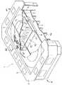
図1は、本発明による競争ゲーム装置を示す斜視図であり、図2は、図1におけるII−II線についての断面図である。図1及び2に示す競争ゲーム装置1は、競技板2上で競走馬を模した模型体60を走行させて競馬レースを再現し、各模型体60の着順を予想する競馬ゲーム装置として構成されている。各模型体60は、競技板2の下方を走行可能な模型体誘導装置40と磁力によって結合し、模型体誘導装置40の走行に伴って誘導される。模型体誘導装置40の下方には、レーザ光等の誘導光Lを投射可能な光誘導装置20が複数配設されている。各光誘導装置20は、1台の模型体誘導装置40に対して誘導光Lを投射すると共に、この誘導光Lの投射位置を変化させて模型体誘導装置40を任意の位置に誘導する。
【0015】
競技板2は、非磁性体(例えば、アルミハニカム材等)からなる板材であり、その上面には、例えば、全長3000mm、全幅1500mm程度の環状をなす走行トラック3が形成されている。走行トラック3は、競技板2上面に複数枚の人工芝3aを両面テープ等を介して貼着することにより、芝面を表現したものである。これにより、競争ゲーム装置1によって実行されるゲーム展開は、より実感的なものとなる。この人工芝3aは、外径0.1mm程度で、長さが1〜1.5mm程度のナイロン等からなる高摺動用エンジニアリングプラスチック製繊維(商品名:リュブマー、三井石油化学工業社製)を厚さ0.3mm程度のPVC製シートに静電植毛したものであり、耐摩耗性及び低摩擦特性に優れる。
【0016】
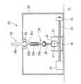
競技板2の周囲には、操作テーブル4が固定されており、この操作テーブル4がフレーム6によって水平に支持されている。操作テーブル4には、複数の操作パネル5が配設されている。各操作パネル5には、図示しないモニタ、コイン投入口、コイン払出口等が設けられており、遊戯者は、この操作パネル5を操作して入賞が期待される模型体を予想した上で、単式、複式又は馬連方式で投票することができる。競技板2の下方には、ベースプレート7が設けられている。このベースプレート7は、フレーム6及び複数の補強フレーム6aによって水平に支持されている。そして、ベースプレート7上には、競技板2の長手方向に延在する一対のガイドレール8が固定されている。
【0017】
また、ベースプレート7上には、このガイドレール8に沿って移動可能な移動装置10が配されている。移動装置10は、上部が解放された直方体の箱状に形成された車台11を有する。この車台11の全長(競技板2の長手方向における長さ)は例えば、約1000mmであり、図2に示すように、競技板2の全長のおよそ3分の1程度である。車台11の全長は、競技の展開における先頭の模型体60と末尾の模型体60の距離差を再現する上で必要とされる長さであればよく、任意に設定すればよい。また、車台11の全幅は、競技板2の全幅とほぼ同一である。車台11の下部四隅には、車輪12が取り付けられている。これらの車輪12は、モータ及び減速機構等からなる駆動部14によって回転駆動されてガイドレール8上を転動する。これにより、移動装置10は、ベースプレート7を走行領域として、競技板2の長手方向に沿って前後移動することができる。なお、移動装置10の移動方向、移動速度等は、移動装置10に搭載された制御部70によって制御される。
【0018】
車台11の底板上面には、競技板2上の模型体の数と同数の光誘導装置20が搭載されている。更に、車台11の上部には、透明ガラス板、透明プラスチック板等により形成された透光板15が固定され、光誘導装置20を覆っている。透光板15は、図1に示すように、車台11の4辺の上縁部のみによって支持され、競技板2と対向すると共に平行をなす。この透光板15上には、競技板2上の模型体の数と同数の模型体誘導装置40が配されている。すなわち、この透光板15は、模型体誘導装置40の走行領域としての役割を果たす。各光誘導装置20は、透光板15を介して誘導光Lを上方に投射する。そして、各模型体誘導装置40は、透光板15を透過した誘導光Lに誘導されて透光板15上を走行すると共に、競技板2を介して模型体60を誘導する。
【0019】
ここで、この競争ゲーム装置1のように、光誘導装置20が発する誘導光Lを用いて模型体60(模型体誘導装置40)を誘導する場合、模型体60を競技板2上の所望位置に誘導するためには、模型体誘導装置40を競技板2に対する所望位置の下方に誘導しなければならず、この際、当然のことながら、模型体誘導装置40を配するための透光板15は、模型体誘導装置40の下方に存在していなければならない。これを踏まえて、この競争ゲーム装置1では、模型体誘導装置40が配される透光板15を、競技板2下方のベースプレート7上を移動可能な移動装置10の上部に取り付けている。これにより、移動装置10を競技板2の下方で移動させれば、透光板15を競技板2の下方全体、すなわち、走行トラック3の下方全体に行き渡らせることができる。
【0020】
このように、移動装置10を競技板2の下方で移動可能なものとすることにより、大きさ(規模)の異なる競争ゲーム装置に大して一の移動装置10を共用することも可能となる。すなわち、一台の移動装置10を、直線コース部分の長い競争ゲーム装置から、直線コースの短い競争ゲーム装置まで適用することができるので、競争ゲーム装置の開発コストを削減可能であり、また、設計の自由度が大きくなる。
【0021】
また、上述したように、競技板2の下方を移動可能な移動装置10(車台11)の全長は、競技板2の全長よりも短く(およそ3分の1程度)、この移動装置10に取り付ける透光板15の面積は、競技板2の面積よりも小さいものとすることができる。これにより、誘導光Lを良好に透過させることができる薄い1枚の透光板15を移動装置10に対して撓みを生じさせることなく強固に固定することが可能となり、同時に、競技板2に対する透光板15の位置精度が向上する。従って、透光板15として、強度を確保するために板厚の厚い透明ガラス等を用いたり、複数の透明ガラス等を継ぎ合わせたりすることも不要となり、誘導光Lの進行を妨げる補強用の梁等を設ける必要は全くない。また、誘導光Lは、屈折することなく良好な状態で透光板15を透過するので、透光板15上で模型体誘導装置40を正確に誘導することができる。更に、競争ゲーム装置1全体の重量を低減可能であると共に、製造コストを低減でき、組立性も向上するので、競争ゲーム装置1を設計する際の自由度が向上する。
【0022】
図3及び4に、移動装置10の車台11に搭載された光誘導装置20を示す。これらの図面に示す光誘導装置20は、レーザ光等の誘導光Lを発生可能な発光器30を有する。この発光器30の先端に設けられた発光部30aは、筐体38の上面から上方に突出している。発光器30は、それぞれ互いに直交する方向に水平移動可能な第一移動部材21及び第二移動部材22によって任意の方向に指向させられ、発光部30aからは、誘導光Lが任意の方向に投射される。
【0023】
第一移動部材21は、図3及び4に示すように、中空の直方体状を呈する枠体として形成される。第一移動部材21の互いに対向し合う一対の壁部21aの下部には、互いに対向し合う雌ねじ孔が形成されており、この雌ねじ孔には、ボールねじ23が螺合される。ボールねじ23は、第一方向(図3におけるX方向)に沿って延在し、軸受け部24を介して筐体38の底部に固定される。また、ボールねじ23の一端には、筐体38の底部に固定された第一パルスモータ25が接続されている。従って、この第一パルスモータ25を介してボールねじ23を回転させることにより、第一移動部材21は、移動装置10の車台11に固定された透光板15に対して第一方向に水平移動することができる。なお、この競争ゲーム装置1では、第一方向として、移動装置10の移動方向すなわち、競技板2の長手方向を採用している。
【0024】
一方、2つの壁部21aと、これら壁部21aとそれぞれ直交し、互いに対向し合う壁部21bによって形成される空間部には、第二移動部材22が配される。第二移動部材22は、直方体形状を有するブロック体として形成される。第二移動部材22には、水平方向に延びる雌ねじ孔がもうけられており、この雌ねじ孔には、ボールねじ26が螺合される。ボールねじ26は、2つの壁部21bによって支持され、第一方向と直交する第二方向(図3におけるY方向)に延在する。また、ボールねじ26の一端には、一方の壁部21bに固定された第二パルスモータ27が接続されている。従って、この第二パルスモータ27を介してボールねじ26を回転させることにより、第二移動部材22は、移動装置10の車台11に固定された透光板15に対して第二方向に水平移動することができる。
【0025】
また、第一パルスモータ25と第二パルスモータ27を同時に駆動させた場合は、第一移動部材21は、透光板15に対して第一方向に水平移動し、第二移動部材22は、第一移動部材21と共に第一方向に水平移動するとともに、透光板15に対して第二方向に水平移動する。なお、パルスモータ25及び27の駆動制御は、制御部70によって行われる。また、ボールねじ23、26は、台形ねじで代用してもよく、これにより、コスト削減が可能となる。
【0026】
ここで、第二移動部材22は、発光器30を保持する連結部材29とボールジョイントを介して連結されている。すなわち、第二移動部材22の上面からは、ボール受部28が延長されている。一方、伸縮部材29の下端部には、ボール部29aが形成されており、ボール部29aはボール受部28にはめ込まれている。これにより、第二移動部材22と連結部材29とは互いに球面対偶を形成し、連結部材29と第二移動部材22とが滑らかかつ柔軟に連結されるので、光誘導装置20の動作を確実かつスムースなものにすることができる。
【0027】
また、連結部材29の上端側には、ボールブシュ部29bが形成されている。一方、連結部材29に保持される発光器30には、発光部30aの反対側に延長された軸部30cが形成されており、この軸部30cがボールブシュ部29bに挿入されている。これにより、発光器30は、連結部材29とともに一直線上に延在すると共に、連結部材29によって伸縮自在に保持される。
【0028】
更に、発光器30は、筐体38の上面中央部に形成された発光器保持部39によってボールジョイントを介して保持されており、発光器30と発光器保持部39とは、互いに球面対偶を形成する。すなわち、発光器保持部39は、ボール受部として形成されており、この発光器保持部39に、発光器20の発光部30aと軸部30cの間に形成されたボール部30bがはめ込まれている。このように、発光器30と発光器保持部39とをボールジョイントを介して連結することより、発光器30と発光器保持部39とが滑らかかつ柔軟に連結されるので、光誘導装置20の動作を確実かつスムースなものにすることができる。ここで、発光器保持部39は、第二移動部材22の上方、かつ、第一移動部材21の水平移動の中心と第二移動部材22の水平移動の中心とを結ぶ直線上に位置決めされている。
【0029】
この光誘導装置20から誘導光Lを模型体誘導装置40に対して投射し、模型体誘導装置40を第一方向に沿って誘導する場合について、図5を参照しながら説明する。まず、第一移動部材21を第一方向に沿って水平移動させる。第一移動部材21が水平移動を開始すると、第二移動部材22も第一移動部材21と共に第一方向に沿って水平移動する。この第二移動部材22の水平移動に伴い、第二移動部材22と球面対偶を形成している連結部材29は、第一移動部材21及び第二移動部材22の移動方向とは反対に向けて倒れるように回動する。この際、発光器30は、発光器保持部39と球面対偶を形成すると共に、連結部材29によって伸縮自在に保持されているので、連結部材29と一直線上に延在すると共に、発光器保持部39周りに、第一移動部材21及び第二移動部材22の移動方向とは反対に向けて倒れるように回動する。
【0030】
ここで、第一方向をX軸方向とし、第二方向をY軸方向とすれば、模型体誘導装置40に対する誘導光Lの投射位置P(誘導光の受光位置)のXY座標は、次のようにして簡単に求めることができる。すなわち、誘導光Lの投射位置PのX座標Pxは、第一移動部材22のX軸方向における原点からの移動量をMxとし、模型体誘導装置40の下面(受光部44)から発光器保持部39までの間の距離をD1とし、発光器保持部39から連結部材29と第二移動部材22との結合点(ボール受部28と連結部材29との結合点)までの間の距離をD2とすれば、Px=−Mx×D1/D2として求まる。
【0031】
同様に、模型体誘導装置40を第二方向に沿って誘導する場合は、第二移動部材22を第二方向に沿って水平移動させれば、発光器30は、発光器保持部39周りに、第二移動部材22の移動方向とは反対に向けて倒れるように回動する。また、誘導光の投射位置PのY座標Pyは、第二移動部材のY軸方向における原点からの移動量をMyとし、模型体誘導装置40の下面から発光器保持部39までの間の距離をD1とし、発光器保持部39から連結部材29と第二移動部材22との結合点との間の距離をD2とすれば、Py=−My×D1/D2として求まる。従って、第一移動部材21と第二移動部材22とを同時に水平移動させることにより、発光器30から誘導光Lを任意の位置に投射することができる。
【0032】
このように、光誘導装置20を用いれば、第一移動部材21及び第二移動部材22の水平移動量を制御すれば、容易かつ自在に誘導光Lの投射位置を定めることができるので、模型体誘導装置40を介して模型体60を競技板2上で様々な軌跡を描くよう走行させることができる。また、第一移動部材21及び第二移動部材22の駆動は、それぞれ独立のものとすることができると共に、例えば、第一移動部材21の移動に伴って第二移動部材22が希望しない方向に移動した分の移動量を補正するといった必要がなくなる。従って、制御プログラム等も簡単なもので済むと共に、光誘導装置全体の構造も簡易なものとなる。
【0033】
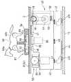
上述した光誘導装置20に案内され、移動装置10の透光板15上で競技板2に対して走行する模型体誘導装置40は、図6及び図7に示すように、透光板15側に位置する下車台41と、競技板2側に位置する上車台42とを有する。下車台41の前側(図7における左側)には、左右一対のキャスタ輪43fが取付軸の周りに回動自在に固定されており、各キャスタ輪43fは、模型体誘導装置40の走行に従って随時方向を転換しながら透光板15上を転動する。同様に、下車台41の後側には、模型体誘導装置40の走行に従って方向転換可能であり、透光板15上を転動するキャスタ輪43rが取り付けられている。キャスタ輪43f、43rは、従輪として機能し、これにより、模型体誘導装置40は、透光板15上を任意の方向に滑らかに移動(スライド)自在となる。更に、下車台41には、透光板15と対向する受光部44が固定されている。模型体誘導装置40は、この受光部44を介して光誘導装置20から発せられた誘導光Lを受け取る。
【0034】
図7に示すように、上車台42は、複数のコイルスプリング45を介して下車台41に連結されており、これらのコイルスプリング45によって、上車台42は、競技板2の下面に対して付勢されている。この上車台42の上面には、模型体60マグネット46が固定されており、模型体誘導装置40は、このマグネット46の磁力によって競技板2を介して模型体60と結合する。更に、上台車42の上面には、集電ユニット47が設けられており、模型体誘導装置40は、この集電ユニット47を介して競技板2の下面に設けられた図示しない給電板から電力の供給を受ける。この集電ユニット47は、図6に示すように、同心円上に配列させた12本の電極を円盤上面から突出させると共に、図示しないスプリングによって給電板に対して付勢させるものである。
【0035】
また、上車台42の後側には、競技板2の下面を転動するの駆動輪48と、この駆動輪48を駆動するパルスモータ51等を一体化させた走行駆動ユニット50が備えられている。一体化された走行駆動ユニット50は、図7に示すように、スプリング52を介して上車台42に取り付けられている。これにより、走行駆動ユニット50は、スプリング52によって競技板2に対して付勢されるので、駆動輪48は、競技板2の下面と確実に接触し、走行駆動ユニット50による駆動力が確実に競技板2の下面に伝えられる。図6に示すように、駆動輪48は一輪であるので、模型体誘導装置の全幅を抑えることができる。駆動輪48の左右側方には、模型体誘導装置40の安定性を向上させるために、補助輪49が配設されている。補助輪49は、通常、競技板2の下面とは接触してはいない。すなわち、模型体誘導装置40が透光板15上で傾いた場合、何れかの補助輪49が競技板2の下面と接触し、模型体誘導装置40が転倒することが防止される。
【0036】
このように、模型体誘導装置40は、競技板2の下面を転動する車輪48、つまり、模型体誘導装置40の上側に位置する車輪48を駆動して走行するものである。ここで、模型体誘導装置40の上側、すなわち、模型体誘導装置40と競技板2との間には、模型体誘導装置40を進行させるための駆動力が進行方向に作用すると共に、競技板2を介して模型体60を誘導する際に生ずる抵抗力や集電ユニット47と給電板との間に生ずる抵抗力等の走行抵抗が模型体誘導装置40の進行方向と反対の方向に作用する。これに対して、模型体誘導装置40の下側では、キャスタ輪43f及び従輪43rとが透光板15上を転動することによる転がり抵抗のみが生じるため、模型体誘導装置40と、走行領域としての透光板15との間に発生する走行抵抗は極めて小さいものとなる。
【0037】
従って、模型体誘導装置40を走行させるための駆動力、及び、走行に伴って作用する走行抵抗のうち負荷が大きいものが、模型体誘導装置40の上側、すなわち、模型体誘導装置40と競技板2の下面との間に集中することになるため、模型体誘導装置40の走行に伴って発生するモーメントは極めて小さなものとなり、模型体誘導装置40の走行効率が向上する。これにより、この模型体誘導装置40は、競技板2の下方を極めてスムースに走行するので、競技板2を介して模型体誘導装置40に誘導される模型体60も、極めてスムースかつ実感的に競技板上を走行することになる。
【0038】
一方、上車台42の前側には、模型体誘導装置40の方向を転換させるための操舵機構53が備えられている。操舵機構53は、競技板2の下面を転動する左右の操舵輪54と、各操舵輪54を同軸上に支持する車輪支持部55とを含む。両操舵輪54は、車輪支持部55に設けられた軸周りにそれぞれ回転自在に支持されている。車輪支持部55は、取付軸(回転軸)56を介して上車台42の上部に固定されると共に、パルスモータ57によって取付軸56周りに回転駆動される。すなわち、この模型体誘導装置40に備えられる操舵機構53は、図6に示すように左右の操舵輪54を一体として、両操舵輪54の中心点(取付軸56)の周りに旋回させるものである。
【0039】
この操舵機構53を作動させた際には、左右各操舵輪54の軸の延長線は常に旋回中心と交わることになる。これにより、操舵輪54の競技板下面に対する横滑りを原理的に少なくすることができるので、回頭性に優れた小回りの利く模型体誘導装置40を実現することができる。また、車輪支持部55を回転駆動するためのパルスモータ57等も単一のものでよいことから、構造が簡単になると共に、操舵角の制御も極めて容易なものとなる。
【0040】
また、左右の操舵輪54を、パルスモータ等の駆動手段51Aによって駆動させてもよく、このような構成を採用した模型体誘導装置40Aを図8に示す。同に示すように、この模型体誘導装置40Aでは、左右の操舵兼駆動輪54Aは、ディファレンシャルギヤ58を介してパルスモータ51Aによって駆動される。そして、これらの操舵兼駆動輪54A、ディファレンシャルギヤ58、パルスモータ51A等は走行駆動ユニット50Aとして一体化されている。そして、この走行駆動ユニット50Aを、伝達機構59を介して、走行駆動ユニット50Aの後方に配置されたパルスモータ57Aによって回転駆動させる。このような模型体誘導装置40Aも、優れた直進安定性及び回頭性をもつものである。
【0041】
なお、上述した操舵機構53は、上側、すなわち、競技板2側に設けられるものとして説明したが、これに限られるものではない。すなわち、左右の操舵輪を一体的に回転駆動する操舵機構は、下側、すなわち、透光板15側に設けてもよく、また、透光板15側に駆動輪を設けた模型体誘導装置に適用することも可能である。
【0042】
模型体誘導装置40によって誘導される模型体60は、図7に示すように、走行トラック3上を滑走可能な模型体キャリア61に取り付けられている。この模型体キャリア61は、例えば、ABS樹脂等によってそり状に形成されており、その底面は、耐摩耗性及び低摩擦特性に優れる。また、上述したように、この模型体キャリア61が走行する走行トラック3に貼着されている人工芝3aは、耐摩擦性及び低摩擦特性を有する高摺動用エンジニアリングプラスチックによって形成されている。従って、この模型体キャリア61は、人工芝3aによる表面処理が施された走行トラック3上を極めてスムースに走行することができる。また、人工芝3aが摩耗して擦り減ることが低減される。
【0043】
このように、模型体キャリア61を滑走体として形成することにより、競争ゲーム装置1によって実行されるゲーム展開の実感味を損なう要因の一つである車輪を模型体キャリアに設ける必要がなくなり、競争ゲーム装置1によって実行されるゲーム展開を極めて実感的なものとすることができる。なお、模型体キャリア61の底部には、模型体誘導装置40に取り付けられたマグネット46と結合するマグネット62が内蔵されている。
【0044】
また、模型体キャリア61の表面には、走行トラック3と同様に、高摺動用エンジニアリングプラスチックを用いて形成した人工芝3aが貼着されている。このように、模型体キャリア61と走行トラック3に対して同一の表面処理を施すことにより、模型体キャリア61が走行トラック3によって隠蔽されるので、模型体キャリア61がより一層目立たないものとなる。従って、競争ゲーム装置1の遊戯者に対して、あたかも、模型体60自体が走行トラック3の上を走行しているような印象を与えることが可能となる。
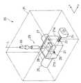
【0045】
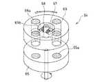
ところで、この模型体60の頭部60a及び脚部60bは、図示しない駆動部及び制御部によって動作させられるものである。このように模型体60を動作させるための電力は、図6、7及び図9に示す発電装置64によって供給される。この発電装置64には、競技板2を介して磁力によって互いに結合する回転部材65と磁場生成部材69とが含まれる。回転部材65は、模型体誘導装置40の上面におけるマグネット66と集電ユニット67との間から鉛直方向に突出するモータ66の回転軸に取り付けられ、このモータ66によって回転駆動される。回転部材65は、4個のマグネット65aが同心円上に等間隔を隔てて配列された円盤体として形成されている(図6参照)。各マグネット65aは、模型体誘導装置40が透光板15上を走行する際に、競技板2と対向する。
【0046】
一方、模型体キャリア61には、図7に示すように、2つのコイル67を固定させたコア68、及び、磁場生成部材69が内蔵されている。コア68は、模型体キャリア61の底壁に固定され、その軸線は鉛直上方に延びる。2つのコイル67は、コア68の周面から互いに逆方向に突出するとともに、同一直線上に延在する。磁場生成部材69は、回転部材65と同様に、4個の磁場生成マグネット69aが同心円上に等間隔を隔てて配列されると共に、中央に開口部69bをもった円盤体として形成されている(図9参照)。そして、磁場生成部材69は、開口部69bにコア68を挿通させた状態で、コア68の周りに回転自在に支持されている。
【0047】
この競争ゲーム装置1では、模型体誘導装置40によって模型体60を誘導してゲーム展開を実行する間に、模型体誘導装置40に設けられた回転部材65をモータ66によって回転駆動する。この際、模型体キャリア61に設けられた磁場生成部材69は、競技板2を介して磁力によって回転部材65と結合し、回転部材65の回転方向に回転することになる。そして、磁場生成部材69の回転に伴ってコイル67内の磁場が変動することにより、コイル67に誘導起電力が生じると共に、誘導電流が流れる。従って、この誘導電流を図示しない集電ブラシ等を用いて取り出すことにより、模型体60に効率よく電力を供給できる。なお、損失を低減させ、効率よく電力を供給するために、模型体誘導装置40と回転部材65との間に非磁性体材料を介在させるか、模型体誘導装置40の上面を非磁性体材料によって形成することが望ましい。
【0048】
この発電装置64によって供給される電力を利用して模型体60の脚部等を動かす他、馬体全体を上下動させたり、旋回走行中に馬体を傾かせるといったように、模型体60自体を動作させることにより、あたかも、模型体60自体が走行トラック上を走行しているような印象を与えることが可能となり、競争ゲーム装置1によって実行されるゲーム展開を実感的なものとすることができる。また、図2及び7では、図示を省略しているが、競走馬として形成した模型体60に、騎手を模した人形を搭載してもよい。この場合は、発電装置64によって供給される電力を利用して、騎手の人形を上下動させたり、手綱や鞭を振らせたり、一着でゴールした際に手を挙げさせたりすることにより、競争ゲーム装置1によって実行されるゲーム展開を極めて実感的なものとすることができる。
【0049】
なお、このように模型体誘導装置40から模型体キャリア61に対して電力を供給するために、模型体誘導装置40と模型体キャリア61とにそれぞれコイルを内蔵させてもよい。この場合、模型体誘導装置40側のコイルに電流を流せば、模型体キャリア61側のコイルに誘導電流が流れることになり、この電流を取り出すことにより、模型体60に電力を供給できる。また、模型体60を動作させる手段として発電装置64を構成する代わりに、機械的に模型体60を動作させる手段を設けてもよい。この場合は、鉛直上方に延びる伝動軸を有し、磁力によって回転部材65と結合する回転体を模型体キャリア61に設けると共に、伝動軸の回転によって頭部60a及び脚部60b等を動作させる駆動機構を模型体60に設けるとよい。更に、競走ゲーム装置1を自動車レースゲームとして構成した場合には、発電装置64による電力を利用して、模型自動車のライト点灯させること等が考えられる。
【0050】
上述したように構成された競走ゲーム装置1においてゲームを実行する際には、移動装置10を競技板2の下方で、競技板2の長手方向に沿うように、走行領域としてのベースプレート7及びガイドレール8上を移動させることにより、競技板2の下方の所望位置に透光板15を移動させる。模型体誘導装置40は、透光板15を介して光誘導装置20によって投射される誘導光Lに誘導され、競技板2の下面を走行する。模型体誘導装置40は、誘導光Lに誘導されながら走行駆動部50の作動によって競技板2に対して移動(自走)する。一方、ベースプレート7上を移動する移動装置10の透光板15に対しては、模型体誘導装置40は滑った状態にある。すなわち、模型体誘導装置40の競技板2に対する移動(自走)は、移動装置10の移動(走行)に規制されることはない。そして、競技板2上の模型体60が模型体誘導装置40によって誘導され、所定のゲーム展開が実行されることになる。
【0051】
【発明の効果】
本発明による競争ゲーム装置は、以上説明したように構成されているため、次のような効果を得る。すなわち、走行トラック上を滑走可能な模型体キャリアを設けたり、走行トラックと模型体キャリアとに対して同一の表面処理を施したり、電磁誘導を利用して模型体に電力を供給する発電装置を備えることにより、実感味あふれるゲーム展開の再現を可能とする競争ゲーム装置の実現が可能となる。
【図面の簡単な説明】
【図1】本発明による競走ゲーム装置を示す斜視図である。
【図2】図1におけるII−II線についての断面図である。
【図3】光誘導装置を示す斜視図である。
【図4】図3の光誘導装置を示す部分断面図である。
【図5】誘導光の投射状態を示す部分断面図である。
【図6】模型体誘導装置を示す斜視図である。
【図7】模型体誘導装置及び模型体を示す部分断面図である。
【図8】模型体誘導装置の他の実施形態を示す断面図である。
【図9】発電装置の構成を示す斜視図である。
【符号の説明】
1…競争ゲーム装置、2…競技板、3…走行トラック、7…ベースプレート、10…移動装置、15…透光板、20…光誘導装置、21…第一移動部材、22…第二移動部材、29…連結部材、30…発光器、39…発光器保持部、40、40A…模型体誘導装置、48…駆動輪、50…走行駆動部、51…パルスモータ(駆動手段)、54…操舵輪、53…操舵機構、55…車輪支持部、56…取付軸、60…模型体、61…模型体キャリア、64…発電装置、65…回転部材、65a…マグネット、67…コイル、68…コア、69…磁場生成部材、69a…磁場生成マグネット、L…誘導光。[0001]
BACKGROUND OF THE INVENTION
The present invention relates to a competitive game apparatus for running a model body on a competition board to reproduce a horse race, an automobile race, and the like and predicting the order of arrival of the model body.
[0002]
[Prior art]
Conventionally, as techniques in such a field, those disclosed in Japanese Patent Laid-Open Nos. 8-821 and 8-822 are known.
[0003]
Each of the conventional competitive game devices described in these publications is a competitive game device that runs a model body on a competition board, reproduces a horse race, a car race, and the like and predicts the order of arrival of the model body. . A running track for running the model body is formed on the competition board (running road surface board, field) of the competitive game apparatus, and the model body is fixed to the carriage and arranged on the running track. Below the competition board, a translucent board (transparent platform, taxiway) having a size corresponding to the size of the running track is arranged. On this translucent plate, a model body guidance device (second carrier, guide car) for guiding the model body on the traveling track is provided. The cart to which the model body is fixed and the model body guidance device each have a magnet and are coupled to each other by a magnetic force via a competition board.
[0004]
In addition, the model body guiding device is supplied with electric power from a power supply plate provided on the lower surface of the competition board via a current collecting unit, and is also provided with a light guiding device (light projector, XY) provided below the light transmitting plate. It is guided by the guide light projected by the optical axis drive unit) and travels on the translucent plate. Therefore, by projecting the guide light from the light guide device and changing the projection position of the guide light, the model body guide device is guided by the guide light and freely travels on the translucent plate. Then, the model body on the game board is guided by the model body guidance device and travels on the traveling track.
[0005]
[Problems to be solved by the invention]
However, the above-described conventional competitive game apparatus has the following problems. That is, when the model body is fixed to the carriage as in the conventional competition game apparatus, the carriage itself and the wheels are conspicuous on the running track, and the horse racing race and the car race reproduced by the competition game apparatus are actually felt. There was a problem of being scarce. Further, in order to increase the actual feeling, it is desirable not only to run the model body, but also to operate the model body itself, for example, by moving the legs of the racehorse model. In this case, a configuration that can efficiently supply power to the model body is required.
[0006]
Therefore, an object of the present invention is to provide a competitive game device that enables realization of game development full of real taste.
[0007]
[Means for Solving the Problems]
The competitive game apparatus according to the present invention as set forth in claim 1 is guided by a model body guidance device capable of traveling on a running area provided below the competition board, and predicts the order of arrival of the model bodies running on the competition board. In a competitive game device, a running track formed on a competition board and running a model body, a model body is mounted, and a model body carrier that is guided by the model body guidance device and can slide on the running track;A rotating member that has a magnet facing the competition board and that is driven to rotate about a rotation axis extending in the vertical direction from the upper surface of the model body guiding device, a core that is fixed to the model body carrier and extends in the vertical direction, and attached to the core A power generator comprising: a coil formed; a plurality of magnetic field generating magnets arranged concentrically around a core; and a magnetic field generating member coupled to a rotating member via a competition board and rotatable around the coreIt is characterized by providing.
[0008]
In this competitive game apparatus, the model body is mounted on a model body carrier that can slide on a running track formed on a competition board. The model body carrier is guided by a model body guidance device that travels below the competition board and slides on the traveling track. In this way, by forming the model carrier as a sliding body, it is possible to omit the cart (wheel), which is one of the factors that impair the actual feeling of the game development executed by the competitive game device, so that the competitive game The game development performed by the device can be very realistic.
[0009]
Further, in this competitive game apparatus, the rotating member provided in the model body guiding apparatus is rotationally driven while the model body is guided by the model body guiding apparatus to execute the game development. At this time, the magnetic field generating member provided in the model carrier is coupled to the rotating member by the magnetic force through the competition board and rotates in the rotating direction of the rotating member. And when the magnetic field in a coil changes with rotation of a magnetic field production | generation member, while an induced electromotive force arises in a coil and an induced current flows. Therefore, by using this induced current, power can be efficiently supplied to the model body. By operating the model itself, such as moving the legs of the racehorse model using this electric power, it is possible to give the impression that the model itself is traveling on the running track. The game development executed by the game device can be made extremely realistic.
[0010]
In this case, it is preferable to apply the same surface treatment to the traveling track and the model carrier. If such a configuration is adopted, the model carrier is concealed by the traveling track, so that the model carrier becomes more inconspicuous. Accordingly, it is possible to give an impression to the player of the competitive game apparatus as if the model itself is traveling on the traveling track.
[0013]
DETAILED DESCRIPTION OF THE INVENTION
Hereinafter, preferred embodiments of a competitive game apparatus according to the present invention will be described in detail with reference to the drawings.
[0014]
FIG. 1 is a perspective view showing a competitive game apparatus according to the present invention, and FIG. 2 is a sectional view taken along line II-II in FIG. A competitive game apparatus 1 shown in FIGS. 1 and 2 is configured as a horse racing game apparatus that reproduces a horse racing race by running a
[0015]
The
[0016]
An operation table 4 is fixed around the
[0017]
Further, a moving
[0018]
The same number of
[0019]
Here, when the model body 60 (model body guidance device 40) is guided using the guide light L emitted from the
[0020]
In this way, by making the moving
[0021]
Further, as described above, the total length of the moving device 10 (chassis 11) that can move below the
[0022]
3 and 4 show the
[0023]
As shown in FIGS. 3 and 4, the first moving
[0024]
On the other hand, the second moving
[0025]
Further, when the
[0026]
Here, the second moving
[0027]
A ball bushing 29 b is formed on the upper end side of the connecting
[0028]
Further, the
[0029]
The case where the guiding light L is projected from the
[0030]
Here, if the first direction is the X-axis direction and the second direction is the Y-axis direction, the XY coordinates of the projection position P (guide light receiving position) of the guide light L with respect to the model
[0031]
Similarly, when the model
[0032]
As described above, if the
[0033]
As shown in FIGS. 6 and 7, the model
[0034]
As shown in FIG. 7, the
[0035]
Further, on the rear side of the
[0036]
As described above, the model
[0037]
Accordingly, the driving force for driving the model
[0038]
On the other hand, a
[0039]
When the
[0040]
Further, the left and
[0041]
In addition, although the
[0042]
As shown in FIG. 7, the
[0043]
In this way, by forming the
[0044]
Similarly to the traveling
[0045]
By the way, the
[0046]
On the other hand, as shown in FIG. 7, the
[0047]
In this competitive game apparatus 1, while the
[0048]
In addition to moving the legs of the
[0049]
In order to supply electric power from the model
[0050]
When the game is executed in the race game device 1 configured as described above, the
[0051]
【The invention's effect】
Since the competitive game device according to the present invention is configured as described above, the following effects are obtained. That is, a power generator that provides a model body carrier that can slide on a traveling track, performs the same surface treatment on the traveling track and the model body carrier, or supplies electric power to the model body using electromagnetic induction. By providing, it is possible to realize a competitive game device that enables reproduction of game development full of real taste.
[Brief description of the drawings]
FIG. 1 is a perspective view showing a racing game apparatus according to the present invention.
FIG. 2 is a cross-sectional view taken along the line II-II in FIG.
FIG. 3 is a perspective view showing a light guiding device.
4 is a partial cross-sectional view showing the light guiding device of FIG. 3;
FIG. 5 is a partial cross-sectional view showing a projection state of guided light.
FIG. 6 is a perspective view showing a model body guiding apparatus.
FIG. 7 is a partial cross-sectional view showing a model body guiding device and a model body.
FIG. 8 is a cross-sectional view showing another embodiment of the model body guiding apparatus.
FIG. 9 is a perspective view illustrating a configuration of a power generation device.
[Explanation of symbols]
DESCRIPTION OF SYMBOLS 1 ... Competitive game device, 2 ... Competition board, 3 ... Running track, 7 ... Base plate, 10 ... Moving device, 15 ... Translucent plate, 20 ... Light guide device, 21 ... First moving member, 22 ... Second moving member , 29 ... connecting member, 30 ... light emitter, 39 ... light emitter holding part, 40, 40A ... model body guiding device, 48 ... drive wheel, 50 ... travel drive part, 51 ... pulse motor (drive means), 54 ... steering Wheel, 53 ... steering mechanism, 55 ... wheel support, 56 ... mounting shaft, 60 ... model body, 61 ... model body carrier, 64 ... power generation device, 65 ... rotating member, 65a ... magnet, 67 ... coil, 68 ...
Claims (2)
Translated fromJapanese前記競技板に形成され、前記模型体を走行させる走行トラックと、
前記模型体が搭載されると共に、前記模型体誘導装置によって誘導されて前記走行トラック上を滑走可能な模型体キャリアと、
前記競技板と対向するマグネットを有すると共に、前記模型体誘導装置の上面から鉛直方向に延びる回転軸周りに回転駆動される回転部材と、前記模型体キャリアに固定されて鉛直方向に延びるコアと、前記コアに取り付けられたコイルと、前記コアを中心として複数の磁場生成マグネットが同心円上に配列されると共に、前記競技板を介して前記回転部材と結合して前記コア周りに回転可能な磁場生成部材とからなる発電装置とを備えることを特徴とする競争ゲーム装置。In a competitive game device that is guided by a model body guidance device capable of traveling on a running area provided below the competition board and predicts the order of arrival of the model body running on the competition board,
A running track formed on the competition board and running the model body;
The model body is mounted, and the model body carrier is guided by the model body guidance device and can slide on the traveling track;
A rotating member that has a magnet facing the game board and is driven to rotate around a rotation axis that extends in the vertical direction from the upper surface of the model body guiding device; a core that is fixed to the model body carrier and extends in the vertical direction; A coil attached to the core and a plurality of magnetic field generating magnets arranged concentrically around the core, and coupled to the rotating member via the competition board and capable of rotating around the coreA competitive game device comprising: a power generation device including a member.
Priority Applications (1)
| Application Number | Priority Date | Filing Date | Title |
|---|---|---|---|
| JP11219198AJP3917752B2 (en) | 1998-04-22 | 1998-04-22 | Competitive game equipment |
Applications Claiming Priority (1)
| Application Number | Priority Date | Filing Date | Title |
|---|---|---|---|
| JP11219198AJP3917752B2 (en) | 1998-04-22 | 1998-04-22 | Competitive game equipment |
Publications (2)
| Publication Number | Publication Date |
|---|---|
| JPH11300028A JPH11300028A (en) | 1999-11-02 |
| JP3917752B2true JP3917752B2 (en) | 2007-05-23 |
Family
ID=14580549
Family Applications (1)
| Application Number | Title | Priority Date | Filing Date |
|---|---|---|---|
| JP11219198AExpired - Fee RelatedJP3917752B2 (en) | 1998-04-22 | 1998-04-22 | Competitive game equipment |
Country Status (1)
| Country | Link |
|---|---|
| JP (1) | JP3917752B2 (en) |
Families Citing this family (1)
| Publication number | Priority date | Publication date | Assignee | Title |
|---|---|---|---|---|
| JP3591771B2 (en)* | 2001-01-10 | 2004-11-24 | コナミ株式会社 | Race game machine |
- 1998
- 1998-04-22JPJP11219198Apatent/JP3917752B2/ennot_activeExpired - Fee Related
Also Published As
| Publication number | Publication date |
|---|---|
| JPH11300028A (en) | 1999-11-02 |
Similar Documents
| Publication | Publication Date | Title |
|---|---|---|
| JP2525828B2 (en) | Tracing change device for racing toys | |
| US4940444A (en) | Miniature vehicle with magnetic enhancement of traction | |
| CN109018119B (en) | Motor-driven device with variable driving mode | |
| JPH067547A (en) | Slot racing truck device | |
| US9162154B2 (en) | Autonomous vehicle system | |
| KR100450860B1 (en) | Game machine using self-propelled members | |
| JPH0738899B2 (en) | Trajectory changing device for racing toys | |
| JP3917752B2 (en) | Competitive game equipment | |
| JP3917751B2 (en) | Competitive game equipment | |
| JPH11300031A (en) | Optical guide apparatus for racing game machine | |
| US6840837B2 (en) | Racing game machine | |
| JPH11300030A (en) | Model body guide device for racing game device | |
| JP3230780B2 (en) | Competitive gaming device | |
| JP4336355B2 (en) | Two-wheeled toy | |
| TWM449621U (en) | Toy vehicle | |
| JP2849991B2 (en) | A game machine for a model vehicle using a magnetically attracted induction vehicle | |
| JPH0956926A (en) | Power feed device for game device | |
| JP2634067B2 (en) | Competitive play equipment | |
| JP3247490B2 (en) | Race play equipment | |
| JP3601453B2 (en) | Moving object control device and game device | |
| JP3247489B2 (en) | Race play equipment | |
| JP3993607B2 (en) | Self-propelled model apparatus, traveling body apparatus and self-propelled vehicle apparatus | |
| JPH11244520A (en) | Horse racing game device | |
| JPH09313744A (en) | Vehicle traveling toy | |
| JPH0647517Y2 (en) | Magnetic induction running toy |
Legal Events
| Date | Code | Title | Description |
|---|---|---|---|
| A711 | Notification of change in applicant | Free format text:JAPANESE INTERMEDIATE CODE: A711 Effective date:20020906 | |
| A621 | Written request for application examination | Free format text:JAPANESE INTERMEDIATE CODE: A621 Effective date:20050118 | |
| A977 | Report on retrieval | Free format text:JAPANESE INTERMEDIATE CODE: A971007 Effective date:20061011 | |
| A131 | Notification of reasons for refusal | Free format text:JAPANESE INTERMEDIATE CODE: A131 Effective date:20061031 | |
| A521 | Written amendment | Free format text:JAPANESE INTERMEDIATE CODE: A523 Effective date:20061220 | |
| A521 | Written amendment | Free format text:JAPANESE INTERMEDIATE CODE: A523 Effective date:20061220 | |
| TRDD | Decision of grant or rejection written | ||
| A01 | Written decision to grant a patent or to grant a registration (utility model) | Free format text:JAPANESE INTERMEDIATE CODE: A01 Effective date:20070206 | |
| A61 | First payment of annual fees (during grant procedure) | Free format text:JAPANESE INTERMEDIATE CODE: A61 Effective date:20070209 | |
| R150 | Certificate of patent or registration of utility model | Free format text:JAPANESE INTERMEDIATE CODE: R150 | |
| FPAY | Renewal fee payment (event date is renewal date of database) | Free format text:PAYMENT UNTIL: 20100216 Year of fee payment:3 | |
| S531 | Written request for registration of change of domicile | Free format text:JAPANESE INTERMEDIATE CODE: R313532 | |
| S533 | Written request for registration of change of name | Free format text:JAPANESE INTERMEDIATE CODE: R313533 | |
| FPAY | Renewal fee payment (event date is renewal date of database) | Free format text:PAYMENT UNTIL: 20100216 Year of fee payment:3 | |
| R350 | Written notification of registration of transfer | Free format text:JAPANESE INTERMEDIATE CODE: R350 | |
| FPAY | Renewal fee payment (event date is renewal date of database) | Free format text:PAYMENT UNTIL: 20100216 Year of fee payment:3 | |
| FPAY | Renewal fee payment (event date is renewal date of database) | Free format text:PAYMENT UNTIL: 20110216 Year of fee payment:4 | |
| FPAY | Renewal fee payment (event date is renewal date of database) | Free format text:PAYMENT UNTIL: 20120216 Year of fee payment:5 | |
| FPAY | Renewal fee payment (event date is renewal date of database) | Free format text:PAYMENT UNTIL: 20130216 Year of fee payment:6 | |
| FPAY | Renewal fee payment (event date is renewal date of database) | Free format text:PAYMENT UNTIL: 20140216 Year of fee payment:7 | |
| R250 | Receipt of annual fees | Free format text:JAPANESE INTERMEDIATE CODE: R250 | |
| R250 | Receipt of annual fees | Free format text:JAPANESE INTERMEDIATE CODE: R250 | |
| R250 | Receipt of annual fees | Free format text:JAPANESE INTERMEDIATE CODE: R250 | |
| R250 | Receipt of annual fees | Free format text:JAPANESE INTERMEDIATE CODE: R250 | |
| LAPS | Cancellation because of no payment of annual fees |