JP3917412B2 - Bill counter - Google Patents
Bill counterDownload PDFInfo
- Publication number
- JP3917412B2 JP3917412B2JP2001359924AJP2001359924AJP3917412B2JP 3917412 B2JP3917412 B2JP 3917412B2JP 2001359924 AJP2001359924 AJP 2001359924AJP 2001359924 AJP2001359924 AJP 2001359924AJP 3917412 B2JP3917412 B2JP 3917412B2
- Authority
- JP
- Japan
- Prior art keywords
- banknote
- detector
- bill
- type
- banknotes
- Prior art date
- Legal status (The legal status is an assumption and is not a legal conclusion. Google has not performed a legal analysis and makes no representation as to the accuracy of the status listed.)
- Expired - Fee Related
Links
- 230000004044responseEffects0.000claimsdescription2
- 238000010586diagramMethods0.000description5
- 230000002265preventionEffects0.000description5
- 230000005540biological transmissionEffects0.000description4
- 230000006870functionEffects0.000description4
- 238000000034methodMethods0.000description3
- 238000009825accumulationMethods0.000description2
- 238000007796conventional methodMethods0.000description1
- 238000001514detection methodMethods0.000description1
- 230000000694effectsEffects0.000description1
- 238000002474experimental methodMethods0.000description1
- 239000004973liquid crystal related substanceSubstances0.000description1
- 230000005389magnetismEffects0.000description1
- 238000012545processingMethods0.000description1
- 238000012360testing methodMethods0.000description1
- 238000009941weavingMethods0.000description1
Images


Landscapes
- Inspection Of Paper Currency And Valuable Securities (AREA)
Description
Translated fromJapanese【0001】
【発明の属する技術分野】
本発明は複数種類の真偽判別手段を備えた紙幣計数機に関するもので、特に紙幣の偽造防止対策上の特徴が各々異なっている複数国の紙幣を容易に扱えるようにした紙幣計数機に関する。
【0002】
【従来の技術】
紙幣の真偽判別機能を備えた紙幣計数機としては、大別して2種類ある。
【0003】
第1のタイプの紙幣計数機は、対象紙幣の金種を特定しこの特定された金種の特徴に基づいて真偽判別を行うものである。
【0004】
一方、第2のタイプのものは、金種を特定することなく真偽判別を行うものであって、金種に依存しない特徴によって真偽判別を行うようにしたものである。
【0005】
上記第2のタイプに属するもので、種類の異なった複数の真偽判別手段(検出器)を併用することは公知であり、例えば米国特許第4114804号や同一出願人による特開昭53−44089号公報に示される紙幣計数機がある。
【0006】
これらの公報には真偽判別手段として、磁気インク検出のための手段と蛍光反応検出のための手段とが開示されており、被検紙幣について磁気インクが検出されて且つ蛍光反応未検出であった場合に、この被検紙幣を真券と判断するようにしている。
【0007】
【発明が解決しようとする課題】
そもそも上記公報のものは、その明細書中にも述べられているように、専ら米国紙幣を想定したものであり、米国紙幣の特徴に合わせて真偽判別手段を選定し組合せたものである。
【0008】
ところでユーロ圏においては、ユーロ紙幣のみならず世界的に流通している米国ドル純幣を扱える真偽判別機能を備えた紙幣計数機が望まれていている。さらにユーロ圏近隣国においては、上記ユーロ紙幣及び米国ドル紙幣に加えて自国の紙幣も扱える真偽判別機能を備えた紙幣計数機が望まれている。
【0009】
各国毎に偽造防止対策の内容が異なっており、例えば、赤外線吸収インクの採用、スレッドの織り込み等様々な工夫がなされていて、これらの紙幣を扱えるようにするためには、赤外線吸収インク検出器やスレッド検出器の採用が当然必要となる。
【0010】
これら種々の偽造防止対策に対応する複数の真偽判別機能を搭載することで、多くの国の紙幣を扱える汎用の紙幣計数機とすることができることになる。
【0011】
ところが、この汎用の紙幣計数機を使いこなすためには、操作者が被検紙幣についての偽造防止対策の内容を知得した上で、この偽造防止対策に対応した真偽判別の検出器の設定を行う必要があるため、煩雑な設定操作を強いられ使い勝手の悪いものとなってしまう。
【0012】
本発明は上記に鑑みなされたものであり、主要な発行国の紙幣(例えばユーロ紙幣や米国ドル紙幣)については、その偽造防止対策に対応する真偽判別に有効な検出器を指定することを必要とせずに、ただ、当該発行国の紙幣の種類を指定するのみで計数が可能な紙幣計数機の提供を目的としている。
【0013】
【課題を解決するための手段】
本発明は、偽造防止対策に対応する真偽判別に有効な検出器を指定することを必要とせずに、ただ、当該発行国の紙幣の種類を指定するのみで計数が可能な紙幣計数機に関し、本発明の上記目的は、複数の紙幣が載置される紙幣載置部と、該紙幣載置部に載置された前記紙幣を1枚ずつ繰出す繰出手段と、該繰出手段によって繰出された前記紙幣を集積部へと搬送する搬送手段と、前記繰出手段と前記集積部との間に位置し前記紙幣についての真偽判別を行う判別原理の異なる複数種類の検出器で構成される真偽判別手段とを有する紙幣計数機において、紙幣の種類と該紙幣に対応して前記判別原理の異なる複数種類の検出器の中から選択された検出器群とが関連付けられて予め記憶されている紙幣種類記憶手段と、該紙幣種類記憶手段に記憶された紙幣の種類を計数対象紙幣として選択する紙幣種類選択手段とをさらに有し、該紙幣種類選択手段により紙幣が選択されることに応じて、前記紙幣種類記憶手段に予め記憶されている対応する前記検出器群を特定し、該特定された検出器群によって真偽判別を行うことを特徴とする紙幣計数機によって達成される。
【0014】
また、本発明の上記目的は、前記紙幣種類記憶手段に予め記憶される紙幣の種類を、少なくともユーロ紙幣と米国ドル紙幣を含むようにすることにより、さらには、該米国ドル紙幣を、100ドル額面のものとそれ以外の額面のものとに区別し、各々に対して判別原理の異なる複数種類の検出器にて真偽判別するようにすることによって、より効果的に達成される。
【0015】
【発明の実施の形態】
図1は本発明に係る紙幣計数機の外観図であり、同図中10は紙幣載置部、20は集積部、30は操作/表示部、40は図示しない搬送手段により送られてきた紙幣を1枚毎に各々の羽根間に受け止めて集積部20に整列集積させる羽根車をそれぞれ示している。
【0016】
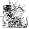
図2は紙幣計数機全体にわたる断面図であり、同図中10は紙幣載置部、20は集積部、30は操作/表示部、40は羽根車、50は繰出手段としての繰出ローラ、60は搬送手段としての搬送ローラ、70は複数種類の検出器で構成される判別ブロック、80は集積部20に紙幣があるか否かを検出するためのスタッカセンサをそれぞれ示している。
【0017】
図3は真偽判別のための検出器の配置等を示すものである。図3(a)は判別ブロック70の配置を示す図であり、図2において1点鎖線で囲った部分を拡大し、模式化したものである。また、図3(b)は、図3(a)を上方向から見た図であり、各検出器の相対的な位置関係を示した図である。同図中71は磁気インクを検出する磁気ヘッドからなる磁気検出器であり、72は紫外線照射光源72aと可視光受光素子72bとからなり、紫外線照射光源72aから照射された紫外線により被検紙幣からの蛍光反射光の有無を可視光受光素子72bで検出するタイプの反射型の蛍光反応検出器であり、73は紙幣のスレッドを検出するスレッド検出器であり、74は赤外線照射光源74aと赤外光受光素子74bとからなり、赤外線照射光源74aから照射された赤外線が被検紙幣を透過した後の赤外線の量を赤外光受光素子74bで検出するタイプの透過型の赤外検出器であり、75は紫外線照射光源72aから照射された紫外線が被検紙幣を透過した後の紫外線の量を検出するタイプの透過型の紫外検出器である。又100は各々の検出器を通過中の紙幣を模式的に示したものである。
【0018】
図4は紙幣計数機の上部に設けられている操作/表示部30の一例を示す図であり、表示部31は計数結果を表示する役目を果たすものであり、例えば7セグメントや液晶パネル等により構成される。判別モード選択手段兼紙幣種類選択手段32は、CFキーとテンキー35との組み合わせによって所定の検出器を選択したり被検紙幣の種類を選択したりするためのものである。
【0019】
本実施例においては、例えば、CFキー32押下後に「7/UV」キーを押せば、紫外検出器が有効となり、その状態でさらに「8/MG」キーを押せば、紫外検出器と磁気検出器の両方が有効となる。この結果、CFキーの右隣のUV及びMGの表示ランプが点灯し、これらの検出器が選択されたことを表示する。
【0020】
また、CFキー32押下後に「1」キーを押せばUS100ドル紙幣が選択されたことになり、後述の紙幣種類記憶手段110に記憶されているUS100ドル用の検出器群が選択される。本実施例の場合は、後述のように、この1回の操作によって、磁気検出器、蛍光反応検出器、紫外検出器の3つの検出器が選択されることになる。従って、操作者はUS100ドル対応の検出器の種類を知らなくても、US100ドルを選択するだけで真偽判別を行うことができる。33、34は計数スタートキーであり、前者はAUTO START キーであり、後者はRESTARTキーである。
【0021】
図5は本実施の形態に係るブロック図である。同図において判別ブロック70は都合5種類の検出器から構成される。磁気検出器71として例えば周知の磁気ヘッドが利用できる。蛍光反応検出器72は紫外線照射光源72aと可視光受光素子72bとで構成される。スレッド検出器73としては例えばヨーロッパ公開特許EP413534に開示されるものを利用できる。赤外検出器74は赤外線照射光源74aと赤外光受光素子74bとで構成される。紫外検出器75は透過型の紫外光受光素子で構成される。搬送手段60は紙幣を判別ブロックに送り込むものである。スタッカセンサ80は集積部の紙幣有無検知を行うものである。操作/表示部30は偽造の疑いがある紙幣を発見したときにこれを表示する。判別モード選択手段兼幣種類選択手段32は、以下のいずれかのために使用するためのものである。
【0022】
第1には、被検紙幣の偽造防止対策の内容を知っている操作者が、該被検紙幣に有効な検出器を選択指定するものであり、この場合、上述のように、例えばCFキー32を押下し、続いてテンキーと兼用の8/MGキーを押下すれば、磁気検出器71によって真偽判別が行われる。これが判別モード選択であり、従来の方法である。
【0023】
第2には、本発明に係るもので、紙幣の種類を指定選択するだけで、指定選択された紙幣に有効な検出器が自動的に選択されるようにするためのものであり、この場合例えばCFキー32を押下し、続いてテンキーの1キーを押下すれば、US100ドルモードとなり、このモードにおいては、磁気検出器71、蛍光反応検出器72及び紫外検出器75によって真偽判別が行われる。紙幣種類記憶手段110には、少なくともユーロ紙幣及び米国ドル紙幣について各々に有効な検出器が何であるか予め登録されている。具件的には、ユーロ紙幣については磁気検出器、蛍光反応検出器、スレッド検出器及び赤外検出器の都合4種類の検出器群が登録され、米国ドル紙幣については磁気検出器及び蛍光反応検出器の都合2種類の検出器群が登録されている。なお、米国ドル紙幣については額面で区別することが好ましい。具体的には、100ドル額面とそれ以外に区別し、100ドル額面については磁気検出器、蛍光反応検出器及び紫外検出器の都合3種類とし、それ以外については前述の磁気検出器及び蛍光反応検出器の都合2種類とすることが、米国ドル紙幣の偽札の現況から見て好ましい。制御部90は図6のフローチャートに示した処理を所定のプログラムに基づいて実行するためのものである。例えばマイクロコンピュータが利用できる。判定条件記憶手段120には、後述のように、真券の場合の各検出器の出力レベルが紙幣の種類毎に記憶されており、このデータと実際の検出値とが比較されて真偽判定がなされる。
【0024】
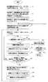
次に、本発明に係る紙幣計数機の動作について、図6のフローチャートに基づいて説明する。なお、図6は被検紙幣がUS100ドルの場合を示しているが、他の紙幣についても同様であることは言うまでもない。
【0025】
まず、紙幣種類選択手段32により、US100ドル紙幣を選択する(ステップS1)。具体的には、CFキー押下後に1キーを押下する。US100ドル紙幣が選択されると、制御部90が紙幣種類記憶手段110に格納されているUS100ドル用の検出器群の選択データを読み出す(ステップS2)。具体的には、磁気検出器71、蛍光反応検出器72及び紫外検出器75の3種類からなる検出器群を選択するものである。このデータに基づいて制御部90は該3種類の検出器の出力のみを有効にするように設定を行う(ステップS3)。この状態で、対象紙幣であるUS100ドル紙幣の束を紙幣載置部10に置く(ステップS4)。
【0026】
次に、操作/表示部30の計数スタートボタン(AUTO START キー)33を押下すると(ステップS5)、紙幣載置部に紙幣があれば(ステップS6の‘YES’)紙幣が搬送され(ステップS7)、対象紙幣が判別ブロックを通過し(ステップS8)真偽判別された後に、紙幣が集積部20に整列集積される(ステップS9)。
【0027】
真偽判別の結果、本物(真券)と判定されると(ステップS10の‘YES’)、ステップS6に戻り紙幣載置部10に紙幣がある限り若しくは偽札と判定されるまでは、ステップS6からステップS10までを繰り返す。
【0028】
一方、ステップS10において偽札と判定されると(ステップS10の‘NO’)、表示部30に偽札である旨の表示をし、搬送手段を停止する(ステップS11)。そこで、すでにカウントされている紙幣の枚数から1を減ずる(ステップS12)とともに、集積部にある偽札を除去する(ステップS13)。その後、ステップS5に戻り、計数スタートボタンを押下し次の紙幣について真偽判別を再開する。このようにして紙幣が紙幣載置部10になくなるまで計数を行い、紙幣がなくなると(ステップS6の‘NO’)、搬送手段を停止する(ステップS14)。そこで、同じ種類の紙幣についてさらに計数を続行するのであれば(ステップS15の‘YES’)、対象紙幣の束を紙幣載置部10に置き(ステップS4)、計数スタートボタンを押下し、計数を再開する(ステップS5)。
【0029】
なお、ステップS10における検出器ごとの真偽判定の条件は次の通りである。
【0030】
(1)磁気検出器…磁気が検出されるものが真券である。
【0031】
(2)蛍光反応検出器…蛍光反応が検知されないものが真券である。従って、蛍光反応があるものは偽札ということになる。
【0032】
(3)紙幣を透過した紫外線の出力が、ある一定のレベルに満たないものが偽札である。偽札は紫外線の透過が少ないという特徴を利用したものであり、基準となるレベルは実験をもとに設定される。
【0033】
(4)スレッド検出器…出力があるものが真券であり、スレッドが存在していることを示している。
【0034】
(5)赤外検出器…真券には赤外線吸収インクが存在しているので、照射した赤外線が吸収され、赤外線の透過量が減る。従って赤外光受光素子74bで検出される受光量が真券と比較して多いのが偽札ということになる。基準レベルは紙幣の種類ごとに予め定められる。
【0035】
以上の判定条件は判定条件記憶手段120に格納されている。
【0036】
本紙幣計数機では多くの国の紙幣を処理可能とする為、都合5種類の検出器を備えているので、本来的には個々の国の紙幣も予め登録しておくべきとの考え方もあるが、その場合、多くのメモリエリアを占有することにもつながり、又操作が煩雑となることから、ごく限られた主要な種類の紙幣のみを登録することとしている。これに伴って、登録されていない紙幣については、従来のように操作者が自らその紙幣に有効な検出器を選択指定する必要が生じる。
【0037】
例えば、ユーロ圏近隣国の一つであるチェコの紙幣を計数対象とする場合には、蛍光反応検出器、スレッド検出器及び赤外検出器の都合3種類の選択指定が必要であり、同じくユーロ圏近隣国の一つであるハンガリーの紙幣を計数対象とする場合には、磁気検出器、蛍光反応検出器及び赤外検出器の都合3種類の選択指定が必要である。
【0038】
【発明の効果】
請求項1の発明では、紙幣の種類毎(発行国毎)に各々の紙幣についてどの検出器が有効であるかを予め登録し、操作者による紙幣の種類の選択操作を行うだけで、選択された紙幣に対応した検出器で真偽判別が行われるようにした。このことにより、選択した紙幣についてどの検出器で真偽判別を行うのかの設定操作が不要となり操作性が向上するし、更に操作者が選択した紙幣についてどの検出器が有効であるかを知らなくてもよいことになる。
【0039】
請求項2の発明では、予め登録する紙幣の種類毎(発行国毎)の紙幣として、少なくともユーロ紙幣と米国ドル紙幣を含めたので、これらの種類の紙幣について操作者による検出器の指定操作が不要となり操作性が向上する。
【0040】
請求項3の発明では、米国ドル紙幣を100ドル額面のものとそれ以外の額面のものとに区分し、各々に対して判別原理の異なる検出器で真偽判別することとし、米国ドル紙幣の偽札の現況に対処できるようになる。
【図面の簡単な説明】
【図1】本発明に係る紙幣計数機の実施例の外観図である。
【図2】紙幣計数機の内部構造を示す縦断面図である。
【図3】真偽判別のための検出器の配置等を示すものである。
【図4】操作/表示部の一例を示す図である。
【図5】本発明に係る紙幣計数機の構成を示すブロック図である。
【図6】本発明に係る紙幣計数機による真偽判別及び計数のフローチャートである。
【符号の説明】
10 紙幣載置部
20 集積部
30 操作/表示部
31 表示部
32 判別モード選択手段兼紙幣種類選択手段
33 計数スタートボタン(AUTO STARTキー)
34 計数スタートボタン(RESTARTキー)
35 テンキー
40 羽根車
50 繰出ローラ
60 搬送ローラ(搬送手段)
70 真偽判別ブロック
71 磁気検出器
72 蛍光反応検出器
73 スレッド検出器
74 赤外検出器
75 紫外検出器
80 スタッカセンサ
90 制御部
100 紙幣
110 紙幣種類記憶手段
120 判定条件記憶手段[0001]
BACKGROUND OF THE INVENTION
The present invention relates to a banknote counter provided with a plurality of types of authenticity discrimination means, and more particularly, to a banknote counter that can easily handle banknotes of a plurality of countries having different characteristics for preventing counterfeiting of banknotes.
[0002]
[Prior art]
There are roughly two types of bill counters equipped with a bill authenticity discrimination function.
[0003]
The first type of banknote counter identifies the denomination of the target banknote and determines authenticity based on the characteristics of the identified denomination.
[0004]
On the other hand, in the second type, authenticity determination is performed without specifying the denomination, and the authenticity determination is performed based on features that do not depend on the denomination.
[0005]
It is known to use a plurality of true / false discrimination means (detectors) belonging to the second type and different types, for example, U.S. Pat. No. 4,114,804 and JP-A-53-44089 by the same applicant. There is a banknote counter shown in the Gazette.
[0006]
These gazettes disclose a means for detecting magnetic ink and a means for detecting a fluorescence reaction as means for determining authenticity, and the magnetic ink is detected for the banknote to be examined and the fluorescence reaction is not detected. When this happens, the banknote to be examined is determined to be a genuine note.
[0007]
[Problems to be solved by the invention]
In the first place, as described in the specification, the above-mentioned publication mainly assumes a US banknote, and selects and combines authenticity determination means in accordance with the characteristics of the US banknote.
[0008]
By the way, in the euro zone, a bill counter having a true / false discrimination function capable of handling not only euro bills but also US dollar pure money distributed worldwide is desired. Further, in the neighboring countries of the euro zone, there is a demand for a banknote counter having a true / false discrimination function that can handle banknotes of the home country in addition to the euro banknotes and US dollar banknotes.
[0009]
The content of anti-counterfeiting measures varies from country to country. For example, the use of infrared absorbing ink, the weaving of threads, and various other measures have been taken. Of course, it is necessary to employ a thread detector.
[0010]
By installing a plurality of authenticity discrimination functions corresponding to these various forgery prevention measures, a general-purpose banknote counter capable of handling banknotes in many countries can be obtained.
[0011]
However, in order to make full use of this general-purpose banknote counter, the operator knows the contents of the counterfeit prevention measures for the banknotes to be examined, and sets the detector for authenticity determination corresponding to the forgery prevention measures. Since it is necessary to perform this, a complicated setting operation is forced and it becomes inconvenient.
[0012]
The present invention has been made in view of the above. For banknotes of major issuing countries (for example, euro banknotes or US dollar banknotes), it is possible to designate a detector that is effective in authenticity determination corresponding to the counterfeit prevention measures. The purpose is to provide a banknote counter capable of counting only by designating the type of banknote in the issuing country.
[0013]
[Means for Solving the Problems]
The present invention relates to a banknote counter capable of counting only by designating the type of banknote of the issuing country, without requiring designation of a detector effective for authenticity determination corresponding to counterfeit prevention measures. The above object of the present invention is paid out by a bill placing portion on which a plurality of bills are placed, a feeding means for feeding the bills placed on the bill placing portion one by one, and the feeding means. Truth comprised of a plurality of types of detectors having different discrimination principles that are positioned between the feeding means and the stacking unit and that determine the authenticity of the banknote. In a bill counter having a false discrimination means, a bill type and a detector group selected from a plurality of types of detectors having different discrimination principles corresponding to the bill are stored in advance in association with each other. Banknote type storage means and the banknote type storage means A bill type selection means for selecting the type of the bills as a bill to be counted, and the correspondence stored in advance in the bill type storage means in response to the bill type being selected by the bill type selection means. This is achieved by a banknote counter characterized by specifying the detector group to be identified and performing authenticity discrimination by the specified detector group.
[0014]
According to another aspect of the present invention, the banknote type stored in the banknote type storage means includes at least a euro banknote and a US dollar banknote. This can be achieved more effectively by distinguishing between the face value and other face values, and making a true / false discrimination with a plurality of types of detectors having different discrimination principles.
[0015]
DETAILED DESCRIPTION OF THE INVENTION
FIG. 1 is an external view of a banknote counter according to the present invention, in which 10 is a banknote placement section, 20 is a stacking section, 30 is an operation / display section, and 40 is a banknote sent by a conveying means (not shown). Is shown between the blades one by one and the impellers are arranged and accumulated on the
[0016]
FIG. 2 is a cross-sectional view of the entire bill counter, in which 10 is a bill placement portion, 20 is a stacking portion, 30 is an operation / display portion, 40 is an impeller, 50 is a feeding roller as feeding means, 60 Is a conveying roller as a conveying means, 70 is a discrimination block composed of a plurality of types of detectors, and 80 is a stacker sensor for detecting whether or not there is a bill in the
[0017]
FIG. 3 shows the arrangement of detectors for authenticity determination. FIG. 3A is a diagram showing the arrangement of the
[0018]
FIG. 4 is a diagram showing an example of the operation /
[0019]
In the present embodiment, for example, if the “7 / UV” key is pressed after the
[0020]
If the “1” key is pressed after the
[0021]
FIG. 5 is a block diagram according to the present embodiment. In the figure, the
[0022]
First, an operator who knows the contents of measures for preventing counterfeiting of a banknote to be selected selects and designates an effective detector for the banknote to be tested. If the user presses 32 and then presses the 8 / MG key, which is also used as a numeric keypad, the
[0023]
Secondly, according to the present invention, it is intended to automatically select a valid detector for a designated and selected bill only by designating and selecting the type of bill. For example, if the
[0024]
Next, operation | movement of the banknote counter which concerns on this invention is demonstrated based on the flowchart of FIG. In addition, although FIG. 6 has shown the case where a test banknote is US $ 100 dollars, it cannot be overemphasized that it is the same also about another banknote.
[0025]
First, a US $ 100 banknote is selected by the banknote type selection means 32 (step S1). Specifically, the 1 key is pressed after the CF key is pressed. When the
[0026]
Next, when the counting start button (AUTO START key) 33 of the operation /
[0027]
As a result of the authenticity determination, if it is determined to be genuine (genuine note) (“YES” in step S10), the process returns to step S6, as long as there is a banknote in the
[0028]
On the other hand, if it is determined in step S10 that it is a fake bill (“NO” in step S10), the
[0029]
The conditions for authenticity determination for each detector in step S10 are as follows.
[0030]
(1) Magnetic detector: A genuine note is one in which magnetism is detected.
[0031]
(2) Fluorescence reaction detector: A genuine card that does not detect a fluorescence reaction. Therefore, a thing with a fluorescence reaction is a fake bill.
[0032]
(3) A counterfeit bill is one in which the output of ultraviolet light that has passed through a bill does not reach a certain level. The counterfeit bill uses the feature of low UV transmission, and the standard level is set based on experiments.
[0033]
(4) Thread detector: An output is a genuine note, indicating that a thread exists.
[0034]
(5) Infrared detector: Since the infrared ray absorbing ink exists in the genuine note, the irradiated infrared ray is absorbed, and the amount of transmitted infrared rays is reduced. Accordingly, the amount of light received detected by the infrared
[0035]
The above determination conditions are stored in the determination condition storage means 120.
[0036]
In order to be able to process banknotes of many countries, this banknote counter is equipped with five types of detectors for convenience, so there is a concept that banknotes of individual countries should be registered in advance. However, in that case, it leads to occupying a lot of memory areas, and the operation becomes complicated. Therefore, only a limited main type of banknote is registered. In connection with this, about the banknote which is not registered, an operator needs to select and specify the detector effective for the banknote like the past.
[0037]
For example, when counting Czech banknotes, one of the neighboring countries of the euro area, it is necessary to select and specify three types of convenience: a fluorescence reaction detector, a thread detector, and an infrared detector. When counting Hungarian banknotes, which are one of the neighboring countries, it is necessary to select and specify three types of convenience: a magnetic detector, a fluorescence reaction detector, and an infrared detector.
[0038]
【The invention's effect】
In the invention of
[0039]
In the invention of claim 2, since at least euro banknotes and US dollar banknotes are included as banknotes for each type of banknote to be registered in advance (for each issuing country), an operation for designating the detector by the operator for these types of banknotes is performed. It becomes unnecessary and the operability is improved.
[0040]
In the invention of
[Brief description of the drawings]
FIG. 1 is an external view of an embodiment of a bill counter according to the present invention.
FIG. 2 is a longitudinal sectional view showing an internal structure of the bill counter.
FIG. 3 shows the arrangement of detectors for authenticity determination.
FIG. 4 is a diagram illustrating an example of an operation / display unit.
FIG. 5 is a block diagram showing a configuration of a banknote counter according to the present invention.
FIG. 6 is a flowchart of authenticity determination and counting by the bill counter according to the present invention.
[Explanation of symbols]
DESCRIPTION OF
34 Count start button (RESTART key)
35
70
Claims (3)
Translated fromJapanese紙幣の種類と該紙幣に対応して前記判別原理の異なる複数種類の検出器の中から選択された検出器群とが関連付けられて予め記憶されている紙幣種類記憶手段と、該紙幣種類記憶手段に記憶された紙幣の種類を計数対象紙幣として選択する紙幣種類選択手段とをさらに有し、
該紙幣種類選択手段により紙幣が選択されることに応じて、前記紙幣種類記憶手段に予め記憶されている対応する前記検出器群を特定し、該特定された検出器群によって真偽判別を行うことを特徴とする紙幣計数機。A bill placing portion on which a plurality of bills are placed, a feeding means for feeding the bills placed on the bill placing portion one by one, and the bills fed by the feeding means to the stacking portion. Banknote counting having transporting means for transporting, and authenticity determination means comprising a plurality of types of detectors having different determination principles for determining authenticity of the banknotes located between the feeding means and the stacking unit. In the machine
Banknote type storage means associated with a banknote type and a detector group selected from a plurality of types of detectors having different discrimination principles corresponding to the banknote, and the banknote type storage means Banknote type selection means for selecting the type of banknote stored in the banknote as the counting target banknote,
In response to the banknote type being selected by the banknote type selection means, the corresponding detector group stored in advance in the banknote type storage means is specified, and authenticity determination is performed by the specified detector group. A bill counter characterized by that.
Priority Applications (5)
| Application Number | Priority Date | Filing Date | Title |
|---|---|---|---|
| JP2001359924AJP3917412B2 (en) | 2001-11-26 | 2001-11-26 | Bill counter |
| EP02075948AEP1241637A3 (en) | 2001-03-16 | 2002-03-08 | Bill counter |
| US10/097,114US6908029B2 (en) | 2001-03-16 | 2002-03-12 | Bill counter |
| KR1020020013834AKR100866353B1 (en) | 2001-03-16 | 2002-03-14 | Bill counter |
| CNB021074437ACN1245700C (en) | 2001-03-16 | 2002-03-15 | Money checking machine |
Applications Claiming Priority (1)
| Application Number | Priority Date | Filing Date | Title |
|---|---|---|---|
| JP2001359924AJP3917412B2 (en) | 2001-11-26 | 2001-11-26 | Bill counter |
Publications (2)
| Publication Number | Publication Date |
|---|---|
| JP2003162753A JP2003162753A (en) | 2003-06-06 |
| JP3917412B2true JP3917412B2 (en) | 2007-05-23 |
Family
ID=19170831
Family Applications (1)
| Application Number | Title | Priority Date | Filing Date |
|---|---|---|---|
| JP2001359924AExpired - Fee RelatedJP3917412B2 (en) | 2001-03-16 | 2001-11-26 | Bill counter |
Country Status (1)
| Country | Link |
|---|---|
| JP (1) | JP3917412B2 (en) |
Families Citing this family (5)
| Publication number | Priority date | Publication date | Assignee | Title |
|---|---|---|---|---|
| JP4495645B2 (en)* | 2005-07-19 | 2010-07-07 | グローリー株式会社 | Banknote transfer device |
| KR100874171B1 (en) | 2008-10-18 | 2008-12-15 | 주식회사 카스모아이티 | Banknote Counter with 2-step Automatic Counterfeit Discrimination |
| KR101460779B1 (en)* | 2013-09-06 | 2014-11-19 | 기산전자 주식회사 | Banknote processing device and control method thereof |
| JP6598705B2 (en)* | 2016-02-22 | 2019-10-30 | グローリー株式会社 | Paper sheet processing apparatus, paper sheet processing system, and paper sheet processing method |
| JP2020046712A (en)* | 2018-09-14 | 2020-03-26 | グローリー株式会社 | Printed matter inspection device and printed matter inspection method |
- 2001
- 2001-11-26JPJP2001359924Apatent/JP3917412B2/ennot_activeExpired - Fee Related
Also Published As
| Publication number | Publication date |
|---|---|
| JP2003162753A (en) | 2003-06-06 |
Similar Documents
| Publication | Publication Date | Title |
|---|---|---|
| KR100866353B1 (en) | Bill counter | |
| US5992601A (en) | Method and apparatus for document identification and authentication | |
| KR101174009B1 (en) | Bill identifier/counter | |
| WO1997030422A1 (en) | Method and apparatus for document identification | |
| US6980684B1 (en) | Method and apparatus for discriminating and counting documents | |
| US6771180B2 (en) | Bill receiving/processing machine | |
| JP3917412B2 (en) | Bill counter | |
| KR20050009503A (en) | Bill counting device which can discriminate counterfeit note from the bill and sum the denomination of the bill and mehtod thereof | |
| JP3599924B2 (en) | Banknote handling equipment | |
| JP4320127B2 (en) | Bill counter | |
| JP2000149086A (en) | Paper money counting and discriminating device | |
| KR200452340Y1 (en) | Bill Counter with Second Run | |
| KR100603184B1 (en) | Banknote Counting Classification System for Differentiation of Counterfeit and Counterfeiting Using UV Sensor | |
| JP4931805B2 (en) | Bill identification counter | |
| KR200328153Y1 (en) | Bill counting device which can discriminate counterfeit note from the bill and sum the denomination of the bill | |
| EP3291186B1 (en) | A bank note handling machine | |
| JP2761177B2 (en) | Money accumulation status judgment device | |
| KR100481680B1 (en) | Bill counting device | |
| GB2347001A (en) | Currency discriminating methods | |
| JP3634562B2 (en) | Currency sorting device | |
| JP3321363B2 (en) | Coin processing equipment | |
| WO2009122503A1 (en) | Coin processor | |
| JP4333493B2 (en) | Coin identification device | |
| JPH01150655A (en) | Paper sheet conveyance device | |
| JPH05182064A (en) | Paper sheet counter |
Legal Events
| Date | Code | Title | Description |
|---|---|---|---|
| A621 | Written request for application examination | Free format text:JAPANESE INTERMEDIATE CODE: A621 Effective date:20040930 | |
| TRDD | Decision of grant or rejection written | ||
| A01 | Written decision to grant a patent or to grant a registration (utility model) | Free format text:JAPANESE INTERMEDIATE CODE: A01 Effective date:20070206 | |
| A61 | First payment of annual fees (during grant procedure) | Free format text:JAPANESE INTERMEDIATE CODE: A61 Effective date:20070208 | |
| R150 | Certificate of patent or registration of utility model | Free format text:JAPANESE INTERMEDIATE CODE: R150 | |
| FPAY | Renewal fee payment (event date is renewal date of database) | Free format text:PAYMENT UNTIL: 20100216 Year of fee payment:3 | |
| FPAY | Renewal fee payment (event date is renewal date of database) | Free format text:PAYMENT UNTIL: 20110216 Year of fee payment:4 | |
| FPAY | Renewal fee payment (event date is renewal date of database) | Free format text:PAYMENT UNTIL: 20120216 Year of fee payment:5 | |
| FPAY | Renewal fee payment (event date is renewal date of database) | Free format text:PAYMENT UNTIL: 20120216 Year of fee payment:5 | |
| FPAY | Renewal fee payment (event date is renewal date of database) | Free format text:PAYMENT UNTIL: 20130216 Year of fee payment:6 | |
| FPAY | Renewal fee payment (event date is renewal date of database) | Free format text:PAYMENT UNTIL: 20130216 Year of fee payment:6 | |
| FPAY | Renewal fee payment (event date is renewal date of database) | Free format text:PAYMENT UNTIL: 20140216 Year of fee payment:7 | |
| FPAY | Renewal fee payment (event date is renewal date of database) | Free format text:PAYMENT UNTIL: 20140216 Year of fee payment:7 | |
| LAPS | Cancellation because of no payment of annual fees |