JP3916311B2 - Information billing system - Google Patents
Information billing systemDownload PDFInfo
- Publication number
- JP3916311B2 JP3916311B2JP33894097AJP33894097AJP3916311B2JP 3916311 B2JP3916311 B2JP 3916311B2JP 33894097 AJP33894097 AJP 33894097AJP 33894097 AJP33894097 AJP 33894097AJP 3916311 B2JP3916311 B2JP 3916311B2
- Authority
- JP
- Japan
- Prior art keywords
- information
- electronic money
- information processing
- control
- terminal unit
- Prior art date
- Legal status (The legal status is an assumption and is not a legal conclusion. Google has not performed a legal analysis and makes no representation as to the accuracy of the status listed.)
- Expired - Fee Related
Links
Images


Classifications
- G—PHYSICS
- G06—COMPUTING OR CALCULATING; COUNTING
- G06Q—INFORMATION AND COMMUNICATION TECHNOLOGY [ICT] SPECIALLY ADAPTED FOR ADMINISTRATIVE, COMMERCIAL, FINANCIAL, MANAGERIAL OR SUPERVISORY PURPOSES; SYSTEMS OR METHODS SPECIALLY ADAPTED FOR ADMINISTRATIVE, COMMERCIAL, FINANCIAL, MANAGERIAL OR SUPERVISORY PURPOSES, NOT OTHERWISE PROVIDED FOR
- G06Q30/00—Commerce
- G06Q30/06—Buying, selling or leasing transactions
- G—PHYSICS
- G06—COMPUTING OR CALCULATING; COUNTING
- G06Q—INFORMATION AND COMMUNICATION TECHNOLOGY [ICT] SPECIALLY ADAPTED FOR ADMINISTRATIVE, COMMERCIAL, FINANCIAL, MANAGERIAL OR SUPERVISORY PURPOSES; SYSTEMS OR METHODS SPECIALLY ADAPTED FOR ADMINISTRATIVE, COMMERCIAL, FINANCIAL, MANAGERIAL OR SUPERVISORY PURPOSES, NOT OTHERWISE PROVIDED FOR
- G06Q20/00—Payment architectures, schemes or protocols
- G06Q20/08—Payment architectures
- G06Q20/10—Payment architectures specially adapted for electronic funds transfer [EFT] systems; specially adapted for home banking systems
- G06Q20/105—Payment architectures specially adapted for electronic funds transfer [EFT] systems; specially adapted for home banking systems involving programming of a portable memory device, e.g. IC cards, "electronic purses"
Landscapes
- Business, Economics & Management (AREA)
- Accounting & Taxation (AREA)
- Finance (AREA)
- Strategic Management (AREA)
- Economics (AREA)
- Development Economics (AREA)
- Physics & Mathematics (AREA)
- General Business, Economics & Management (AREA)
- General Physics & Mathematics (AREA)
- Engineering & Computer Science (AREA)
- Theoretical Computer Science (AREA)
- Marketing (AREA)
- Financial Or Insurance-Related Operations Such As Payment And Settlement (AREA)
- Management, Administration, Business Operations System, And Electronic Commerce (AREA)
- Control Of Vending Devices And Auxiliary Devices For Vending Devices (AREA)
Description
Translated fromJapanese【0001】
【発明の属する技術分野】
本発明は、貨幣に代えてICカードに貯えられた電子マネー情報をやり取りする電子財布システムに用いた電子マネー取り引きシステムに係り、特に、情報処理装置により指示された電子マネー情報の受け渡しに好適な情報課金システムに関する。
【0002】
【従来の技術】
従来のかかる電子財布システムで電子マネー情報のやり取りを行なう情報課金システムでは、例えば、特開平3−92966号公報に記載のように、ICカードをPOS端末などの専用装置に装着することによって行なわれる。これは、主に、信頼性の点で優れたかかる専用装置を用いることにより、電子マネー情報の取り引きの信頼性を確保するためである。
【0003】
【発明が解決しようとする課題】
しかしながら、このように、電子マネー情報のやり取りを行なうのにかかる専用装置を用いなければならないと、ICカードを所持する個人が何らかのサービスを受けたい場合には、その個人は、必ずかかる専用装置が設置されている場所(例えば、店頭)を訪れて、その専用装置にICカードを装着して直接操作することが必要である。このため、従来の電子財布システムでは、電子マネー情報のやり取りの利便性を有効に発揮するものではなかった。
【0004】
本発明の目的は、かかる問題を解消し、電子マネー情報の取り引きの信頼性を確保しつつ、個人所有の端末を用いて電子マネー情報のやり取りを容易に行なうことができるようにした情報課金システムを提供することにある。
【0005】
【課題を解決するための手段】
上記目的を達成するために、本発明は、利用者が所持する端末(以下、個人端末という)に公衆回線を経由したデータ通信手段を設け、該データ通信手段を介して電子マネー情報の移動を行なうことができるようにすることにより、サービスを供給する装置に直接ICカードを差し込む必要がなくなるようにする。
【0006】
また、本発明は、電子マネー情報の移動に必要な部材が独立して動作可能とすることにより、何らかの機器故障が発生しても、開始された電子マネー情報の移動処理を完遂することができるようにする。
【0007】
【発明の実施の形態】
以下、本発明の実施形態を図面を用いて説明する。
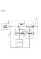
図1は本発明による情報課金システムの第1の実施形態における個人端末を示すブロック図であって、1はICカード、2は端末部、3は切替器、4はモデム装置、5はデータ処理装置、6は制御装置、7は通信回線、8は外部情報処理装置である。
【0008】
同図において、この個人端末は、ICカード1が着脱可能であって、公衆回線などの通信回線7に接続された端末部2と、この端末部2に接続された外部情報処理装置8とから構成されており、ICカード1は内部に電子マネー情報が書き込まれており、端末部2に装着することにより、電子マネー情報の書込みや読出しを行なうことができる。
【0009】
端末部2は切替器3とモデム装置4とデータ処理装置5と制御装置6とによって構成されており、モデム装置4は、電子情報を通信回線7を経由して送受可能とし、切替器3は制御装置6からの切替信号S2によって切替え制御される。
【0010】
切替器3がデータ処理装置5側に閉じているときには、ICカード1と後述するホスト装置との間で電子マネー情報のやり取りを行ない、このICカード1での電子マネー情報の書込みや読出しが行なわれる。書込みの場合には、通信回線7を介して電子マネー情報と制御信号とが入力され、これらがモデム装置4で復調された後、切替器3を介してデータ処理装置5に供給されて所定の処理がなされる。処理された電子マネー情報と制御信号とはICカード1に供給される。ICカード1では、この制御信号で制御されて電子マネー情報がICメモリに書き込まれる。読出しの場合には、通信回線7から同様の経路を経てICカード1に制御信号が供給され、ICカード1では、この制御信号で制御されてICメモリから所定の電子マネー情報が読み出される。この電子マネー情報はデータ処理装置5で処理されて切替器3を通り、モデム装置4で変調された後、通信回線7を介して伝送される。
【0011】
切替器3が外部情報処理装置8側に閉じているときには、キーボードなどの入力装置や表示装置などからなる外部情報処理装置8が切替器3を介してモデム装置4と接続される。これにより、外部情報処理装置8は、通信回線7を介して図示しないホスト装置とデータや制御信号のやり取りを行なう。
【0012】
制御装置6は、外部情報処理装置8との間で制御信号S4のやり取りを行ない、制御装置6はこの制御信号S4に応じてモデム装置4や切替器3,データ処理装置5を制御する。これにより、ホスト装置と外部情報処理装置8との間での通信を可能としたり、ICカード1とホスト装置との間で電子マネー情報のやり取りを可能にする。
【0013】
図2は図1に示した端末部を用いた本発明による情報課金システムの第1の実施形態のシステム構成を示すブロック図であって、9は個人端末、10はホスト装置であり、図1に対応する部分には同一符号をつけている。
【0014】
同図において、ICカード1が着脱可能な端末部2と外部情報処理装置8とからなる個人端末9が複数通信回線7を介して互いに接続されており、同様の構成をなすホスト装置10もこの通信回線7に接続されている。これにより、ホスト装置10と各個人端末9との間で、各種データや制御信号,電子マネー情報のやり取りを行なうことができる。
【0015】
次に、この第1の実施形態の動作について説明する。
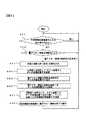
図3は図1における外部情報処理装置8の内部処理動作を示すフローチャートである。
【0016】
同図において、初期状態として、切替器3は外部情報処理装置8側に閉じており、モデム装置4は通信回線7を切断した状態にある。かかる初期状態において、外部情報処理装置8で、例えば、ダイヤル操作などによってホスト装置10を読み出すと、まず、外部情報処理装置8から制御装置6に制御信号S4が供給され、これに応じて制御装置6は制御信号S1を発生し、モデム装置4を制御して通信回線7を接続する。この制御信号S4に続いて外部情報処理装置8から切替器3を介してモデム装置4に呼出し信号が供給され、さらに、通信回線7を介してホスト装置10に送られる。そして、ホスト装置10からこれに対する応答があると、外部情報処理装置8とホスト装置10との間で通信が可能となる(ステップ301)。
【0017】
しかる後、外部情報処理装置8において、入力装置によって購入希望する製品の製品番号を入力すると、この製品番号の情報信号が切替器3,モデム装置4及び通信回線7を介してホスト装置10に送信される(ステップ302)。そこで、ホスト装置10は、送られてきた製品番号に応じた金額情報と送金指示データを通信回線7を介して端末部2に送り返す。これら金額情報と送金指示データとはモデム装置4及び切替器3を介して外部情報処理装置8に送られる(ステップ303)。外部情報処理装置8では、これら金額情報と送金指示データとを処理して表示装置に表示し、使用者にその確認を求める(ステップ304)。
【0018】
そこで、使用者が確認したことを示す操作を行なうと(ステップ305)、外部情報処理装置8はホスト装置10から送られてきた金額情報と送金指示データとに基づいた電子マネー情報の移動を指示する制御信号S4を制御装置6に送出する(ステップ306)。制御装置6がこの制御信号S4を受理したことを確認すると(ステップ307)、電子マネー情報の移動処理終了を待つ。
【0019】
即ち、制御装置6は、制御信号S4を受理すると、制御信号S1でモデム装置4を動作状態とし、制御信号S2で切替器3をデータ処理装置5側に切り替え、制御信号S3でデータ処理装置5を動作状態とし、これとともに、制御信号S4の受理に対する応答信号を外部情報処理装置8に、かかる準備動作が終了したことを示すデータをデータ処理装置5に送る。
【0020】
データ処理装置5は、制御装置6からのデータを受けると、切替器3,モデム装置4及び通信回線7を介してホスト装置10に準備が終了したことを示すデータを送る。これにより、ホスト装置10は、ICカード1から送金すべき金額を示すデータと制御信号とを通信回線7,モデム装置4及び切替器3を介してデータ処理装置5に送り、ここで処理されたこれらデータ及び制御信号がICカード1に送られる。ICカード1では、この制御信号によって制御され、このデータに応じた金額の電子マネー情報が読み出され、データ処理装置5で処理された後、切替器3,モデム装置4及び通信回線7を介してホスト装置10に送られる。
【0021】
これによって送金が終了すると、データ処理装置5から制御装置6に送金の終了信号が、制御装置6を介し、制御信号S4として外部情報装置8に送られる。これにより、制御装置6は、切替器3を外部情報処理装置8側に切り替える。
【0022】
外部情報処理装置8では、この送金終了の制御信号S4を受けると(ステップ308)、送金終了を示すデータを切替器3,モデム装置4及び通信回線7を介してホスト装置10に送り、これに応じてホスト装置10は、通信回線7,モデム装置4及び切替器3を介して外部情報処理装置8に送る。これにより、この外部情報処理装置8では、ICカード1からホスト装置6に送金された金額が表示される(ステップ309)。
【0023】
かかる状態で、他に購入希望の製品がある場合には、外部情報処理装置8の入力装置でその製品番号を入力すると、この製品について、ステップ303〜309の一連の動作が繰り返される。そして、もはや希望する製品がなく、外部情報処理装置8の入力装置で終了の操作をすると(ステップ310)、外部情報処理装置8から終了を示す制御信号S4が制御装置6に供給され、これにより、制御装置6は制御信号S1を発生してモデム装置4を制御し、通信回線7を切断する(ステップ311)。このとき、後述するように、切替器3は制御装置6の制御によって外部情報処理装置8側に閉じており、これにより、上記の初期状態となる。
【0024】
なお、ステップ302では、希望する製品が複数ある場合には、これらの製品番号を一度に入力することができる。この場合には、夫々の製品番号毎にステップ303〜308の一連の動作が繰り返され、全ての製品番号に対する送金が終了すると(ステップ308)、送金が終了したことと夫々の送金金額が表示される(ステップ309)。しかる後、使用者の終了操作とともに、通信回線7が切断される(ステップ311)。
【0025】
以上のようにして、この実施形態では、製品購入のための電子マネー情報の移動に関する処理が行なわれることになる。
【0026】
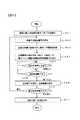
図4は図1における制御装置6の内部処理動作を示すフローチャートである。
【0027】
同図において、まず、切替器3により、モデム装置4と外部情報処理装置8とが接続されている。外部情報処理装置8は、通信回線7を経由してホスト装置10と交信して、電子マネー情報について、その金額やその移動方向(送金方向)などの基礎情報を予め決め、その後、制御装置6に金額とその送金方向の情報に加えて電子マネー情報の移動の開始を指示する制御信号S4を送る。
【0028】
そこで、制御装置6は、この指示信号である制御信号S4を受け(ステップ401)、これが電子マネー情報の移動開始を指示したものであれば(ステップ402)、その金額と移動方向とを読み込む(ステップ403)。そして、これらを受理したことを示す情報を制御信号S4として外部情報処理装置8に返し、制御信号S2を発生して切替器3を制御し、これを切り替えてモデム装置4をデータ処理装置5に接続する(ステップ404)。
【0029】
かかる切替器3の操作が完了した後、制御装置6はデータ処理装置5に電子マネー情報の移動を指示するデータを制御信号S3として送出する(ステップ405)。これにより、データ処理装置5は、切替器3,モデム装置4及び通信回線7を介し、ICカード1とホスト装置10との間で電子マネー情報の移動を開始させ、この移動する電子マネー情報の処理を行なう。かかる移動が完了すると、データ処理装置5は電子マネー情報の移動終了を示す制御信号S3を制御装置6に送る。
【0030】
そこで、制御装置6は、この制御信号S3を受け取ると(ステップ406)、制御信号S2を発生して切替器3を外部情報処理装置8側に切り替え、外部情報処理装置8をモデム装置4を介して通信回線7に接続するとともに(ステップ407)、外部情報処理装置8に電子マネー情報の移動終了を示す制御信号S4を送り、次の指示を示す制御信号S4が外部情報処理装置8から送られてくるまで待機する(ステップ401)。
【0031】
以上のように外部情報処理装置8や端末部2の制御装置6が動作することにより、この第1の実施形態では、ICカード1の電子マネー情報を支払ってサービスを受けようとする使用者は、単に外部情報処理装置8を操作して確認の動作を行なうことのみで、電子マネー情報のやり取りを容易に行なうことができる。
【0032】
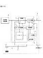
図5は本発明による情報課金システムの第2の実施形態における個人端末を示すブロック図であって、11はデータ判別装置、12は入力装置、13は表示装置であり、図1に対応する部分には同一符号を付けて重複する説明は省略する。なお、この第2の実施形態においても、全体的なシステム構成は図2に示すものと同様である。
【0033】
同図において、この実施形態では、端末部2に入力装置12と表示装置13とが設けられて夫々制御装置6に接続され、また、外部情報処理装置8はデータ判別装置11を介して切替器3と接続されている。従って、外部情報処理装置8には、図1に示した第1の実施形態とは異なり、入力装置や表示装置が設けられていない。以上の点以外は、図1に示した個人端末と同様である。
【0034】
なお、データ判別装置11は、外部情報処理装置8からのデータを解析し、切替器3,モデム装置4及び通信回線7を介してホスト装置10に送る情報信号であるか、制御装置6に送る制御信号S4であるかを判別する。
【0035】
次に、この第2の実施形態の動作について説明するが、ここでも、図1に示した個人端末と同様、通信販売において、製品の購入をする場合の処理について説明する。
【0036】
図6は図5における外部情報処理装置8の内部処理動作を示すフローチャートであるが、その動作はほとんど図3に示した図1における外部情報処理装置8の内部処理動作と同じであるので、図2に対応するステップには同一符号を付けて重複する説明を省略する。
【0037】
同図において、図3で説明したように、電子マネー情報の金額とその移動方向を取得すると(ステップ303)、外部情報処理装置8での確認動作を行なうことなく、制御装置6に移動を指示する(ステップ306)。即ち、この外部情報処理装置8での処理動作としては、図3でのステップ304,305が行なわれない。かかる処理は、表示装置13が端末部2に設けられたことにより、後述するように、制御装置6で行なわれる。
【0038】
なお、データ判別装置11は、外部情報処理装置8が電子マネー情報の移動を制御装置6に指示する場合には、これを判別してこの指示を示す制御信号S4を制御装置6に送り、ホスト装置10へのデータ及び制御信号である場合には、これをそのまま切替器3に供給する。
【0039】
図7は図5における制御装置6の処理動作を示すフローチャートであって、図4に対応するステップには同一符号をつけている。
【0040】
図5における制御装置6の動作は、ほとんどが図4に示した図1における制御装置6の動作と同様であるが、図5において、端末部2に入力装置12と表示装置13とが設けられ、これらを制御装置6が制御するようにした点で、図5における制御装置6の動作が図1における制御装置6の動作と異なっている。この動作の違いは、図7でステップ403とステップ404との間にステップ701,702を設けた点である。なお、これらステップ701,702は図3におけるステップ304,305と同様の処理を行なうものである。
【0041】
図7において、図5における制御装置6は、図1における制御装置6と同様にして、外部情報処理装置8から電子マネー情報の移動開始指令とともに送られて来るこの電子マネー情報の金額と移動方向とを表わす情報を読み込むと(ステップ403)、この情報を表示装置13に表示させ(ステップ701)、次いで、使用者がこれを確認して入力装置12で所定の確認操作をすると(ステップ702)、この確認を示す情報を制御信号S4として外部情報処理装置8に返し、制御信号S2を発生して切替器3を制御し、これを切り替えてモデム装置4をデータ処理装置5に接続する(ステップ404)。これ以降の動作は、図4に示した図1での制御装置6の動作と同様である。
【0042】
以上のように、この第2の実施形態では、外部情報処理装置8が電子マネー情報の金額やその送金方向といった基本的な情報の取得のみを行なう。実際の電子マネー情報の移動は、入力装置12によって使用者がこれら情報の確認入力を行なった後となる。このため、電子マネー情報の移動処理は、その開始から終了までの全てが制御装置6によって行なわれることになる。このようにして、外部情報処理装置8は電子マネー情報の移動処理に何ら関与しないため、第1の実施形態に比べて、電子マネー情報の移動処理がより安全に行なわれることになる。
【0043】
また、この第2の実施形態では、データ判別装置11が設けられているため、モデム装置4に供給されるデータと制御信号は全て、モデム装置4の動作制御のための信号や外部(即ち、通信回線7)に送出するデータである。このため、モデム装置4は、第1の実施形態で行なわれていた外部情報処理装置8の制御装置6に対する制御信号S4の判別を行なう必要がなく、簡易なものとなる。
【0044】
図8は本発明による情報課金システムの第3の実施形態における個人端末を示すブロック図であって、14は電源回路、15は充電回路、16は蓄電池であり、図5に対応する部分には同一符号をつけて重複する説明を省略する。なお、この第3の実施形態でも、全体的なシステム構成は図2に示すものと同様である。
【0045】
同図において、端末部2には、蓄電池16とこの蓄電池16に外部電源(図示せず)から充電する充電回路15とからなる電源回路14が設けられており、この蓄電池16が常に充電されるようになっている。これ以外の構成は、図5に示した第2の実施形態と同様である。切替器3やモデム装置4,データ処理装置5,制御装置6などはこの電源回路14から電源電圧が供給される。
【0046】
次に、この第3の実施形態の動作について説明する。
【0047】
外部情報制御装置5からの指示による切替器3の切替えの動作やモデム装置4と通信回線7とを介した電子マネー情報の移動の動作は第2の実施形態と同様であるが、この際、この第3の実施形態では、蓄電池16の電力によって電子マネー情報の移動を行なう。
【0048】
以上のように、この第3の実施形態では、先の第2の実施形態と同様の効果が得られるとともに、端末部の各装置に別途設けた電源回路14から電源電圧が印加され、しかも、この電源回路14の蓄電池16には、常時外部電源から充電が行なわれているので、例えば、電子マネー情報の移動中に停電が発生しても、これが中断することがなく、電子マネー情報の移動のための処理を完遂させることができる。
【0049】
なお、この第3の実施形態は、図1に示した第1の実施形態の端末部2に電源回路14を設けた構成をなすものであるが、図5に示した第2の実施形態の端末部2に同様の電源回路14を設けるようにすることもでき、同様の効果が得られる。
【0050】
図9は本発明による情報課金システムの第4の実施形態における個人端末を示すブロック図であって、図8に対応する部分には同一符号をつけて重複する説明を省略する。なお、この第4の実施形態においても、全体的なシステム構成は図2に示すものと同様である。
【0051】
同図において、この第4の実施形態では、充電回路15が通信回線7に接続されており、端末部2がこの通信回線7に接続されている間、充電回路15を介して蓄電池16が充電される構成となっている。
【0052】
かかる構成により、外部情報処理装置8からの指示によって行なわれる切替器3の切替えの動作や、モデム装置4と通信回線7とを介した電子マネー情報の移動の動作は図5に示した第2の実施形態と同様である。この際、電源回路14の蓄電池16での電力によって電子マネー情報の移動が行なわれることも図8に示した第3の実施形態と同様である。この第4の実施形態では、通信回線7が接続されることにより、蓄電池16が充電される。
【0053】
以上のように、この第4の実施形態では、上記の第3の実施形態と同様に得られる効果に加えて、蓄電池16の充電を通信回線7からの回線電流で行なうことができるため、外部に電源回路を設ける必要がなくなる。
【0054】
なお、この第4の実施形態は、図1に示した第1の実施形態の端末部2に電源回路14を設けた構成をなすものであるが、図5に示した第2の実施形態の端末部2に同様の電源回路14を設けるようにすることもでき、同様の効果が得られる。
【0055】
図10は本発明による情報課金システムの第5の実施形態における個人端末を示すブロック図であって、17は電源切替器、18は電池であり、図8に対応する部分には同一符号をつけて重複する説明を省略する。なお、この第5の実施形態においても、全体的なシステム構成は図2に示すものと同様である。
【0056】
同図において、この第4の実施形態では、図8に示した第3の実施形態のように、端末部2に図示しない外部電源から電源電圧が供給されるとともに、電源回路14をこの端末部2に備えたものであるが、この電源回路14は電源切替器17と電池18とで構成されている。ここで、電源切替器17は、この外部電源の電源電圧を常時監視しており、この電源電圧が規定値以下に低下すると、電源回路14を端末部2の電源として機能させるものである。
【0057】
かかる構成により、外部情報処理装置8からの指示による切替器3の切替え動作や、モデム装置4と通信回線7とを介した電子マネー情報の移動の動作は図5に示した第2の実施形態と同様である。この際、外部電源からの電力によって電子マネー情報の移動が行なわれるのであるが、停電などによって外部電源から電力が供給されないときには、電源切替器17がこれを検知することにより、電源回路14が電源として作動して、電池18の出力電圧が端末部2の各装置に電源電圧として供給され、電子マネー情報の移動の動作が中断することがない。この場合、電子マネー情報の移動が少なくとも1回は可能となる。
【0058】
以上のようにして、この第5の実施形態では、図5に示した第2の実施形態と同様の効果が得られるとともに、端末部2は、通常、外部電源から電源電圧が供給されて動作し、図8に示した第3の実施形態と同様の効果が得られ、さらに、例えば、停電などによって外部電源からの供給電源電圧が低下した場合には、電源切替器17により、電池18から電源電圧が供給されて電子マネー情報の移動が完遂されることになる。また、この第5の実施形態では、電池18を用いたことにより、図8に示した第3の実施形態のような充電回路が不要となるという効果も得られる。
【0059】
なお、この第5の実施形態は、図1に示した第1の実施形態の端末部2に電源回路14を設けた構成をなすものであるが、図5に示した第2の実施形態の端末部2に同様の電源回路14を設けるようにすることもでき、同様の効果が得られる。
【0060】
図11は本発明による情報課金システムの第6の実施形態における個人端末を示すブロック図であって、19は受光装置、20は発光装置であり、図10に対応する部分には同一符号をつけて重複する説明を省略する。なお、この第6の実施形態においても、全体的なシステム構成は図2に示すものと同様である。
【0061】
同図において、この第6の実施形態では、端末部2に受光装置19が、また、外部情報処理装置8に発光装置20が夫々設けられ、これら発光装置20と受光装置19との間で光信号の伝送が行なわれる。この発光装置20は外部情報処理装置8の内部で制御され、外部情報処理装置8の制御によって希望する光指示信号Lを発生する。この光指示信号Lは受光装置19で受光されて電子的なデータに変換され、制御信号S4として制御装置6に供給される。
【0062】
図12はこの光指示信号Lのデータ構成を示す図である。
同図において、この光指示信号Lは、電子マネー情報の取り引きを示してその移動を指示する情報D1やこの電子マネー情報の移動の方向を示す情報D2,この電子マネー情報の金額を示す情報D3などから構成されている。
【0063】
次に、この第6の実施形態の動作について説明するが、ここでも、図1に示した個人端末と同様、通信販売において、製品の購入をする場合の処理について説明する。
【0064】
図13は図11における外部情報処理装置8の処理動作を示すフローチャートであって、図6に対応するステップには同一符号をつけている。
【0065】
同図において、通信回線7経由でホスト装置10と交信し、製品に対応した必要な電子マネー情報の金額とその移動方向殿情報を取得する動作(ステップ303)までは、図6に示した図5での外部情報処理装置8の動作と同様である。
【0066】
しかる後、外部情報処理装置8は、送り返された金額情報と送金指示データを、図12に示したように、電子マネー情報の移動の方向を示す情報D2とこの電子マネー情報の金額を示す情報D3に変換し、これに電子マネー情報の取り引きを示す情報D1を付加して情報信号を作成し(ステップ1301)、これでもって発光装置20を制御することにより、光指示信号Lに変換して送出する(ステップ1302)。これによって外部情報処理装置8は処理を終了するが、端末部2では、受光装置19がこの光指示信号を受光し、電気信号に変換して、制御信号S4として、制御装置6に供給される。
【0067】
図14は図11における制御装置6の内部処理動作を示すフローチャートであって、図7に対応するステップには同一符号をつけている。
【0068】
同図において、先の各実施形態と同様に、まず、切替器3とモデム装置4とを介して外部情報処理装置8が通信回線7と接続されており、外部情報処理装置8は、通信回線7を経由してホスト装置10と交信し、電子マネー情報の移動について金額や移動方向などの基礎情報を予め決める。
【0069】
その後、外部情報処理装置8が光指示信号Lを用いて電子マネー情報の移動の開始を指示する。受光装置19は光入力を監視しており、この光指示信号Lを受光すると(ステップ1401)、これを電気信号に変えて、制御信号S4として、制御装置6に供給する(ステップ1402)。このとき、この電子マネー情報の金額とその移動方向との情報(図12での情報D3,D2)に加えて、この電子マネー情報の移動開始を指示する情報(図12での情報D1)も伝達される。
【0070】
制御装置6は、この電子マネー情報の移動開始を指示する情報D1を取り込むと(ステップ402)、これとともに送られてきた電子マネー情報の金額を表わす情報D3とその移動方向を示す情報D2とを読み込み(ステップ403)、表示装置20に表示させて使用者がこれらを確認できるようにする(ステップ701)。そこで、使用者が入力装置13を用いて確認したことを示すと(ステップ702)、制御装置6は、制御信号S2で切替器3を制御してモデム装置4をデータ処理装置5に接続し(ステップ404)、データ処理装置5に電子マネー情報の移動を指示する制御信号S3を送出する(ステップ405)。これにより、データ処理装置5は、先の実施形態と同様にして、ICカード1から読み出される電子マネー情報を処理し、切替器3,モデム装置4及び通信回線7を介してホスト装置10に電子マネー情報の移動を開始する。
【0071】
電子マネー情報の移動が終了すると、データ処理装置5は、電子マネー情報の移動終了を示す制御信号S3を制御装置6に送り、制御装置6は、この制御信号S3を受け取ると(ステップ406)、制御信号S1を発生することにより、モデム装置4を制御にして通信回線7を切断し(ステップ1403)、制御信号S2を発生して切替器3を制御し、モデム操作4を外部情報処理装置8側に切り替る(ステップ407)。そして、制御装置6は、移動した電子マネー情報の金額とその移動方向とともに、その移動が完了したことを表示装置13に表示させる(ステップ1404)。
【0072】
以上のようにして、この第6の実施形態の端末部2では、移動する電子マネー情報の金額や移動方向を示す情報を外部情報処理装置8から非接触で受け取ることができる。このため、先の各実施形態で必要であった制御装置6と外部情報処理装置8との間の制御信号S4のための信号線路が不要となる。
【0073】
また、この第6の実施形態では、外部情報処理装置8が電子マネー情報の金額やその送金方向といった基本的な情報の取得のみを行ない、実際の電子マネー情報の移動は、入力装置12により、使用者が確認入力を行なった後となる。このため、電子マネー情報の移動処理は、その開始から終了までの全てを制御装置6が行なうこととなり、先の第1の実施形態に比べて、電子マネー情報の移動処理をより安全に行なうことができる。
【0074】
なお、この第6の実施形態では、電源回路14として、図10に示した第5の実施形態と同様のものを用いたが、図8または図9に示す構成の電源回路14を用いるようにしてもよく、同様の効果が得られる。
【0075】
図15は本発明による情報課金システムの第7の実施形態における個人端末を示すブロック図であって、2a,2bは端末部、21はモデム情報処理装置、22,23は受発光装置であり、前出図面に対応する部分には同一符号をつけて重複する説明を省略する。なお、この第7の実施形態においても、全体的なシステム構成は図2に示すものと同様である。
【0076】
同図において、この第7の実施形態では、端末部が端末部2a,2bに2分割されており、夫々が別々の筐体に収納されている。端末部2aは切替器3,モデム装置4,モデム情報処理装置21及び受発光装置22からなり、また、端末部2bはデータ処理装置5,制御装置6,入力装置12,表示装置13,電源回路14及び受発光装置23からなっている。これら端末部2a,2b間では、受発光装置22,23により、光情報信号L1が伝送される。また、外部情報処理装置8の発光装置20からの光指示信号Lは端末部2bの受発光装置23で受光され、制御信号S4として制御装置6に供給される。端末部2bには、電池18からなる電源回路14が内蔵されており、この電池18の電圧が、電源電圧として、データ処理装置5や制御装置6に印加されている。
【0077】
切替器3はモデム情報処理装置21からの制御信号S2によって制御され、外部情報処理装置8側とモデム情報処理装置21側とのいずれかに選択的に切り替えられる。切替器3がモデム情報処理装置21側に閉じているときには、通信回線7とモデム装置4と切替器3を介して供給される情報信号がモデム情報処理装置21で処理されて受発光装置22に供給され、光情報信号L1に変換されて端末部2bの受発光装置23に送られる。
【0078】
また、端末部2bの受発光装置23からの光情報信号L1は端末部2aの受発光装置22で受光され、電気信号としての情報信号DS1に変換される。この情報信号DS1はモデム情報処理装置21に供給されてその内容が判別される。その内容としては、モデム装置4や切替器3の制御信号S1,S2である場合と、ホスト装置10に送る電子マネー情報に関する情報信号である場合とがある。モデム情報処理装置21は、受発光装置22からの情報信号DS1がモデム装置4や切替器3の制御信号S1,S2であるときには、モデム装置4や切替器3を制御し、電子マネー情報に関する情報信号であるときには、この情報信号DS1を切替器3,モデム装置4及び通信回線7を介してホスト装置10に送る。
【0079】
受発光装置23は、外部情報処理装置8の発光装置20からの図12で示した構成の光指示信号Lの受光手段も備えており、この受光手段で光指示信号Lを受光して得られる電気信号は、先の実施形態と同様、制御信号S4として制御装置6に供給される。
【0080】
図16は図15における光情報信号L1として伝送される情報信号DS1の内容を示す図である。
【0081】
図16(a)は電子マネー情報の伝達の際の情報信号DS1を示している。この情報信号DS1は、この情報信号DS1の送り方向を示す信号D11と電子マネー情報であることを示す情報D12と電子マネー情報D13とによって構成されている。
【0082】
図16(b)は切替器3やモデム装置4の制御を行なう際の情報信号DS1(即ち、制御信号S2,S1)を示している。この情報信号DS1は、切替器3やモデム装置4を制御するものであることを示す情報D21と切替器3やモデム装置4を制御するコマンド信号D22とから構成されている。
【0083】
図16(c)はモデム装置4と切替器3との状態を知らせる情報信号DS1を示している。この情報信号DS1には、モデム装置4と切替器3との状態を表わすものであることを示す情報D31とモデム装置4または切替器3の状態を示すステータス信号D32とから構成されている。
【0084】
図17はICカード1に入出力される電子マネー情報を表わす情報信号DS2を示す図である。
【0085】
ICカード1に入出力される電子マネー情報の情報信号DS2は、ICカード1に暗号化処理されて記憶されており、通常の手段では、ICカード1の記憶内容を改ざんできないようになっている。この暗号化された電子マネー情報を移動させることにより、ICカード1内に貯えれている電子マネー情報を実質的に移動する構成となっている。図16(a)に示した情報信号DS1での電子マネー情報D13は、ICカード1から読み出された電子マネー情報の情報信号DS2をそのまま用いたものである。
【0086】
次に、この第7の実施形態の動作について説明する。
【0087】
図18は図15における外部情報処理装置8の処理動作を示すフローチャートであって、図13に対応するステップには同一符号をつけている。
【0088】
この第7の実施形態においても、通信販売で製品の購入をするものとして説明すると、この場合の外部情報処理装置8の処理動作は、図11における外部情報処理装置8の図13に示した処理動作と同様である。また、この場合の発光装置20から端末部2bの受発光装置23に送られる光情報信号Lは、上記のように、図12に示した構成をなすものである。
【0089】
端末部2の制御装置6は、この受発光装置23の出力を常時監視しており、光指示信号Lを受光したときには、制御装置6は、先の各実施形態のように、この受光に伴なう上記の制御信号S4を取り込んで、各種制御処理を行なう。
【0090】
図19及び図20は図15における制御装置6の処理動作を示すフローチャートであって、図14に対応するステップには同一符号をつけて重複する説明を省略する。
【0091】
図19において、ステップ702までの処理動作は、図11における制御装置6の図14で示す動作と同様である。即ち、受発光装置23は、外部情報処理装置8からの光指示信号Lを受光すると、これを電気的な図12に示す構成の情報信号に変換して制御装置6に供給する。制御装置6は、この情報信号から電子マネー情報の移動指示を示す情報D1を検出すると、電子マネー情報の金額を示す情報D3と移動の方向を示す情報D2とを読み込み、これらを表示装置13で表示させて使用者に確認を求める。以上がステップ701までの処理動作である。
【0092】
使用者が入力装置12で確認の操作をすると(ステップ702)、制御装置6は、図16(b)に示す形式の情報信号DS1をデータ処理装置5を介して受発光装置23に送り、この受発光装置23はこの情報信号DS1の光情報信号L1を発光する。この光情報信号Lは端末部2aの受発光装置22で受光される。受発光装置22はこの光情報信号L1を電気信号である情報信号DS1に変換し、モデム情報処理装置21に供給する。このモデム情報処理装置21はこの情報信号DS1を分析するが、これが図16(b)に示す形式のものであることから、制御信号S1,S2を発生し、モデム装置4を制御して通信回線7が接続された状態に継続させるとともに、切替器3を制御してモデム情報処理装置21側に切り替える。これにより、モデム装置4とデータ処理装置5とが接続されることになる(ステップ1901)。
【0093】
切替器3のかかる切り替わり動作が完了すると、モデム情報処理装置43は、図16(c)に示す形式のモデム装置4と切替器3の状態とを示す情報信号DS1を発生し、上記とは逆に、受発光装置22,23及びデータ処理装置5を介して制御装置6に送る。これにより、制御装置6は、切替器3の切替えが完了したという報告を受けることになり(ステップ1902)、データ処理装置5に電子マネー情報の移動を指示する制御信号S3を送出する(ステップ1903)。
【0094】
そこで、データ処理装置5は、この制御信号S3を受けると、制御装置6の制御のもとに、ICカード1から図17に示す形式の電子マネー情報DS2を読み出し、これに電子マネー情報であることを示す情報D12とこの電子マネー情報の移動方向を示す信号D11を付加して図16(a)に示す形式の情報信号DS1を形成し、受発光装置23,22を介して端末部2aのモデム情報処理装置21に送る。ここで、この情報信号DS1での信号D11は、制御装置6からみて、送信するものであるか、受信するものであるかを示すものである。そこで、モデム情報処理装置21は、この信号D11と情報D12とから、この情報信号DS1はホスト装置10(図2)に送信する電子マネー情報であると判定し、この情報信号DS1を切替器3,モデム装置4及び通信回線7を介してホスト装置10に送る。
【0095】
このようにして、ICカード1から読み出された電子マネー情報DS2はホスト装置10に送られるが、その間制御装置6は待機状態にある(ステップ1904,1907)。
【0096】
また、ホスト装置10から同様の図16(a)に示す形式の電子マネー情報の情報信号DS1が送られてきたときには、モデム情報処理装置21がこれを上記と同様な方法で判定し、受発光装置22,23を介して端末部2bのデータ処理装置5に送る。そこで、制御装置6は、データ処理装置5でこの情報信号DS1から分離された信号D11及び情報D12により、受信された電子マネー情報の情報信号DS1であると判定し、この情報信号DS1での電子マネー情報D13をデータ処理装置5に受信させ(ステップ1905)、図17に示す形式の電子マネー情報DS2としてICカード1に書き込ませる(ステップ1906)。
【0097】
以上のようにして、図16(a)に示す形式の電子マネー情報の情報信号DS1の送信もしくは受信が終了すると、データ処理装置5は電子マネー情報の移動処理の終了信号を制御装置6に送る(ステップ1907)。そこで、制御装置6は、通信回線7を切断するための図16(b)に示す形式の情報信号DS1を、上記のようにして、端末部2aのモデム情報処理装置21に送る(ステップ1908)。このモデム情報処理装置21は、この情報信号DS1に基づいて制御信号S1を発生し、モデム装置4を制御にして通信回線7を遮断するとともに、モデム装置4と切替器3との状態を表わす図16(c)に示す形式の情報信号DS1を、上記のようにして、端末部2bの制御装置6に送る。これにより、制御装置6は通信回線7が切断されたことを検知し(ステップ1909)、電子マネー情報の移動が完了したことを表示装置13に表示させる(ステップ1910)。
【0098】
しかる後、制御装置6は、切替器3を切り替えるための図16(b)に示す形式の情報信号DS1を、上記のようにして、端末部2aのモデム情報処理装置21に送る(ステップ1911)。これにより、モデム情報処理装置21は、制御信号S2を発生して切替器3を制御し、外部情報処理装置8側に切り替えてこの外部情報処理装置8をモデム装置4に接続させるとともに、切替器3とモデム装置4の状態を示す図16(c)に示す形式の情報信号DS1を作成し、端末部2bの制御装置6に送る。制御装置6は、この情報信号DS1を受けて切替器3の切り替え動作が完了したことを検知すると(ステップ1912)、図19にステップ1401に戻って次の光指示信号Lを受信するまで待機する。
【0099】
以上のようにして、この第7の実施形態では、端末部2が、移動する電子マネー情報の金額やその移動方向を情報や電子マネー情報の受け渡しを非接触で行なうことができる。このため、端末部2を独立した筐体とすることできて、独立して持ち運び可能となる。
【0100】
また、この第7の実施形態では、外部情報処理装置8で金額や送金方向といった基本的な情報の取得のみを行ない、実際の電子マネー情報の移動は、入力装置12により、使用者が確認入力を行なった後となる。このため、電子マネー情報の移動処理は、その開始から終了までの全てを制御装置6が行なうこととなり、先の第1の実施形態に比べて、電子マネー情報の移動処理をより安全に行なうことができるようになる。
【0101】
なお、この第7の実施形態では、モデム装置4と外部情報処理装置8を別体に設けたが、モデム装置4の信頼性を確保した上で、外部情報処理装置8とモデム装置4を一体に設けるようにしても何ら問題はない。また、この際、光指示信号の送出のための発光装置20と受発光装置22を1つの部材としても、何ら問題はない。
【0102】
また、この第7の実施形態では、電源回路14として、図8または図10に示す構成の電源回路14を用いるようにしてもよく、同様の効果が得られる。
【0103】
【発明の効果】
以上説明したように、本発明によると、利用者が所持する端末に公衆回線を経由したデータ通信手段を設け、このデータ通信手段を介して電子マネー情報の移動を行なうことが可能となることにより、サービスを供給する専用の装置を使用することなく、ICカードを用いてそのサービスを受けることができる。
【0104】
また、本発明によると、電子マネー情報の移動に必要な装置は、直接電子マネー情報の移動に関与しない他の情報処理装置などの周辺装置とは独立して動作可能とすることにより、これらの周辺装置に何らかの機器故障が発生しても、開始された電子マネー情報の移動処理を完遂することができる。このため、端末本体の信頼性を確保することができ、電子マネー情報の移動処理を個人所有の端末で行なうことが可能となる。
【図面の簡単な説明】
【図1】本発明による情報課金システムの第1の実施形態における個人端末を示すブロック図である。
【図2】本発明による情報課金システムの構成を示す図である。
【図3】図1における外部情報処理装置の処理動作を示すフローチャートである。
【図4】図1における制御装置の処理動作を示すフローチャートである。
【図5】本発明による情報課金システムの第2の実施形態における個人端末を示すブロック図である。
【図6】図5における外部情報処理装置の処理動作を示すフローチャートである。
【図7】図5における制御装置の処理動作を示すフローチャートである。
【図8】本発明による情報課金システムの第3の実施形態における個人端末を示すブロック図である。
【図9】本発明による情報課金システムの第4の実施形態における個人端末を示すブロック図である。
【図10】本発明による情報課金システムの第5の実施形態における個人端末を示すブロック図である。
【図11】本発明による情報課金システムの第6の実施形態における個人端末を示すブロック図である。
【図12】図11における光指示信号の構成を示す図である。
【図13】図11における外部情報処理装置の処理動作を示すフローチャートである。
【図14】図11における制御装置の処理動作を示すフローチャートである。
【図15】本発明による情報課金システムの第7の実施形態における個人端末を示すブロック図である。
【図16】図11における各種の光情報信号の構成を示す図である。
【図17】図11における電子マネー情報の構成を示す図である。
【図18】図15における外部情報処理装置の処理動作を示すフローチャートである。
【図19】図11における制御装置の処理動作の前半部分を示すフローチャートである。
【図20】図11における制御装置の処理動作の後半部分を示すフローチャートである。
【符号の説明】
1 ICカード
2,2a,2b 端末部
3 切替器
4 モデム装置
5 データ処理装置
6 制御装置
7 通信回線
8 外部情報処理装置
9 個人端末
10 ホスト装置
11 データ判別装置
12 入力装置
13 表示装置
14 電源回路
15 充電回路
16 蓄電池
17 電源切替器
18 電池
19 受光装置
20 発光装置
21 モデム情報処理装置
22,23 受発光装置[0001]
BACKGROUND OF THE INVENTION
The present invention relates to an electronic money transaction system used in an electronic wallet system for exchanging electronic money information stored in an IC card instead of money, and is particularly suitable for delivery of electronic money information instructed by an information processing apparatus. The present invention relates to an information billing system.
[0002]
[Prior art]
In a conventional information billing system for exchanging electronic money information using such an electronic wallet system, for example, as described in Japanese Patent Laid-Open No. 3-92966, the IC card is mounted on a dedicated device such as a POS terminal. . This is mainly to ensure the reliability of electronic money information transactions by using such a dedicated device that is excellent in reliability.
[0003]
[Problems to be solved by the invention]
However, as described above, if a dedicated device for exchanging electronic money information must be used, if an individual who possesses an IC card wants to receive some service, the individual must have the dedicated device. It is necessary to visit a place where the device is installed (for example, a storefront) and directly operate the IC card attached to the dedicated device. For this reason, the conventional electronic wallet system does not effectively demonstrate the convenience of exchanging electronic money information.
[0004]
SUMMARY OF THE INVENTION An object of the present invention is an information billing system which can easily exchange electronic money information using a personally owned terminal while solving such problems and ensuring the reliability of electronic money information transactions. Is to provide.
[0005]
[Means for Solving the Problems]
In order to achieve the above object, according to the present invention, a terminal (hereinafter referred to as a personal terminal) possessed by a user is provided with data communication means via a public line, and electronic money information is transferred via the data communication means. By making it possible to do so, it is not necessary to insert the IC card directly into the device supplying the service.
[0006]
In addition, the present invention can complete the started electronic money information transfer process even if any device failure occurs by enabling the members necessary for the transfer of electronic money information to operate independently. Like that.
[0007]
DETAILED DESCRIPTION OF THE INVENTION
Hereinafter, embodiments of the present invention will be described with reference to the drawings.
FIG. 1 is a block diagram showing a personal terminal in a first embodiment of an information billing system according to the present invention, wherein 1 is an IC card, 2 is a terminal unit, 3 is a switch, 4 is a modem device, and 5 is data processing. 6 is a control device, 7 is a communication line, and 8 is an external information processing device.
[0008]
In this figure, this personal terminal includes an
[0009]
The
[0010]
When the
[0011]
When the
[0012]
The
[0013]
2 is a block diagram showing a system configuration of a first embodiment of the information billing system according to the present invention using the terminal unit shown in FIG. 1, wherein 9 is a personal terminal, 10 is a host device, and FIG. The parts corresponding to are assigned the same reference numerals.
[0014]
In this figure, a personal terminal 9 comprising a
[0015]
Next, the operation of the first embodiment will be described.
FIG. 3 is a flowchart showing the internal processing operation of the external
[0016]
In the figure, as an initial state, the
[0017]
After that, when the product number of the product desired to be purchased is input by the input device in the external
[0018]
Therefore, when the user performs an operation indicating confirmation (step 305), the external
[0019]
That is, when the
[0020]
When the
[0021]
When the remittance is completed, a remittance end signal is sent from the
[0022]
When the external
[0023]
In this state, when there is another product desired to be purchased, when the product number is input by the input device of the external
[0024]
In
[0025]
As described above, in this embodiment, processing relating to movement of electronic money information for product purchase is performed.
[0026]
FIG. 4 is a flowchart showing the internal processing operation of the
[0027]
In the figure, first, the
[0028]
Therefore, the
[0029]
After the operation of the
[0030]
Therefore, when receiving the control signal S3 (step 406), the
[0031]
As described above, when the external
[0032]
FIG. 5 is a block diagram showing a personal terminal in the second embodiment of the information billing system according to the present invention, wherein 11 is a data discriminating device, 12 is an input device, 13 is a display device, and corresponds to FIG. The same reference numerals are assigned to the same components, and duplicate descriptions are omitted. In the second embodiment, the overall system configuration is the same as that shown in FIG.
[0033]
In this embodiment, in this embodiment, an input device 12 and a
[0034]
The data discriminating device 11 analyzes the data from the external
[0035]
Next, the operation of the second embodiment will be described. Here, as in the case of the personal terminal shown in FIG. 1, the processing for purchasing a product in mail order will also be described.
[0036]
6 is a flowchart showing the internal processing operation of the external
[0037]
In FIG. 3, as described with reference to FIG. 3, when the amount of electronic money information and the movement direction thereof are acquired (step 303), the
[0038]
When the external
[0039]
FIG. 7 is a flowchart showing the processing operation of the
[0040]
The operation of the
[0041]
7, the
[0042]
As described above, in the second embodiment, the external
[0043]
In the second embodiment, since the data discriminating device 11 is provided, all data and control signals supplied to the
[0044]
FIG. 8 is a block diagram showing a personal terminal in the third embodiment of the information billing system according to the present invention, wherein 14 is a power supply circuit, 15 is a charging circuit, 16 is a storage battery, and the portion corresponding to FIG. The same reference numerals are assigned and duplicate descriptions are omitted. In the third embodiment, the overall system configuration is the same as that shown in FIG.
[0045]
In the figure, the
[0046]
Next, the operation of the third embodiment will be described.
[0047]
The switching operation of the
[0048]
As described above, in the third embodiment, the same effects as those of the second embodiment can be obtained, and the power supply voltage is applied from the
[0049]
In the third embodiment, the
[0050]
FIG. 9 is a block diagram showing a personal terminal in the fourth embodiment of the information billing system according to the present invention. The parts corresponding to those in FIG. In the fourth embodiment, the overall system configuration is the same as that shown in FIG.
[0051]
In this figure, in the fourth embodiment, the charging
[0052]
With this configuration, the switching operation of the
[0053]
As described above, in the fourth embodiment, in addition to the effects obtained in the same manner as in the third embodiment, the
[0054]
In the fourth embodiment, the
[0055]
FIG. 10 is a block diagram showing a personal terminal in the fifth embodiment of the information billing system according to the present invention. 17 is a power switch, 18 is a battery, and parts corresponding to those in FIG. Therefore, duplicate explanations are omitted. In the fifth embodiment, the overall system configuration is the same as that shown in FIG.
[0056]
In this figure, in the fourth embodiment, as in the third embodiment shown in FIG. 8, a power supply voltage is supplied to the
[0057]
With this configuration, the switching operation of the
[0058]
As described above, in the fifth embodiment, the same effect as that of the second embodiment shown in FIG. 5 is obtained, and the
[0059]
The fifth embodiment has a configuration in which the
[0060]
FIG. 11 is a block diagram showing a personal terminal in the sixth embodiment of the information billing system according to the present invention. 19 is a light receiving device, 20 is a light emitting device, and parts corresponding to those in FIG. Therefore, duplicate explanations are omitted. In the sixth embodiment, the overall system configuration is the same as that shown in FIG.
[0061]
In this figure, in the sixth embodiment, a
[0062]
FIG. 12 is a diagram showing a data configuration of the light instruction signal L. As shown in FIG.
In this figure, this light instruction signal L indicates information D1 indicating a transaction of electronic money information and instructing its movement, information D2 indicating the direction of movement of this electronic money information, and information D3 indicating the amount of this electronic money information. Etc.
[0063]
Next, the operation of the sixth embodiment will be described. Here, as with the personal terminal shown in FIG. 1, the processing for purchasing a product in mail order sales will also be described.
[0064]
FIG. 13 is a flowchart showing the processing operation of the external
[0065]
In FIG. 6, the process up to the communication with the
[0066]
Thereafter, the external
[0067]
FIG. 14 is a flowchart showing the internal processing operation of the
[0068]
In the figure, as in the previous embodiments, first, an external
[0069]
Thereafter, the external
[0070]
When the
[0071]
When the movement of the electronic money information is finished, the
[0072]
As described above, the
[0073]
In the sixth embodiment, the external
[0074]
In the sixth embodiment, the
[0075]
FIG. 15 is a block diagram showing a personal terminal in the seventh embodiment of the information billing system according to the present invention, 2a and 2b are terminal units, 21 is a modem information processing device, 22 and 23 are light emitting and receiving devices, Parts corresponding to those in the previous drawings are assigned the same reference numerals and redundant description is omitted. In the seventh embodiment as well, the overall system configuration is the same as that shown in FIG.
[0076]
In the same figure, in this 7th Embodiment, the terminal part is divided into 2 by the terminal parts 2a and 2b, and each is accommodated in the separate housing | casing. The terminal unit 2a includes a
[0077]
The
[0078]
The optical information signal L1 from the light emitting / receiving device 23 of the terminal unit 2b is received by the light emitting / receiving
[0079]
The light emitting / receiving device 23 is also provided with a light receiving means for the light instruction signal L having the configuration shown in FIG. 12 from the
[0080]
FIG. 16 is a diagram showing the contents of the information signal DS1 transmitted as the optical information signal L1 in FIG.
[0081]
FIG. 16A shows an information signal DS1 when electronic money information is transmitted. The information signal DS1 includes a signal D11 indicating the sending direction of the information signal DS1, information D12 indicating electronic money information, and electronic money information D13.
[0082]
FIG. 16B shows an information signal DS1 (that is, control signals S2 and S1) when the
[0083]
FIG. 16C shows an information signal DS1 that informs the state of the
[0084]
FIG. 17 is a diagram showing an information signal DS2 representing electronic money information inputted to and outputted from the
[0085]
The information signal DS2 of electronic money information input / output to / from the
[0086]
Next, the operation of the seventh embodiment will be described.
[0087]
FIG. 18 is a flowchart showing the processing operation of the external
[0088]
Also in the seventh embodiment, if it is assumed that a product is purchased by mail order, the processing operation of the external
[0089]
The
[0090]
19 and 20 are flowcharts showing the processing operation of the
[0091]
19, the processing operation up to step 702 is the same as the operation shown in FIG. 14 of the
[0092]
When the user performs a confirmation operation with the input device 12 (step 702), the
[0093]
When the switching operation of the
[0094]
Therefore, upon receiving this control signal S3, the
[0095]
In this way, the electronic money information DS2 read from the
[0096]
When the information signal DS1 of the electronic money information in the format shown in FIG. 16A is sent from the
[0097]
When the transmission or reception of the information signal DS1 of the electronic money information in the format shown in FIG. 16A is completed as described above, the
[0098]
Thereafter, the
[0099]
As described above, in the seventh embodiment, the
[0100]
In the seventh embodiment, the external
[0101]
In the seventh embodiment, the
[0102]
In the seventh embodiment, the
[0103]
【The invention's effect】
As described above, according to the present invention, the terminal possessed by the user is provided with data communication means via a public line, and electronic money information can be transferred via this data communication means. The service can be received using an IC card without using a dedicated device for supplying the service.
[0104]
In addition, according to the present invention, devices necessary for moving electronic money information can operate independently of peripheral devices such as other information processing devices that are not directly involved in moving electronic money information. Even if some device failure occurs in the peripheral device, the started electronic money information transfer process can be completed. For this reason, the reliability of the terminal body can be ensured, and electronic money information transfer processing can be performed by a personally owned terminal.
[Brief description of the drawings]
FIG. 1 is a block diagram showing a personal terminal in an information billing system according to a first embodiment of the present invention.
FIG. 2 is a diagram showing a configuration of an information billing system according to the present invention.
FIG. 3 is a flowchart showing a processing operation of the external information processing apparatus in FIG. 1;
4 is a flowchart showing a processing operation of the control device in FIG. 1. FIG.
FIG. 5 is a block diagram showing a personal terminal in the second embodiment of the information charging system according to the present invention.
6 is a flowchart showing a processing operation of the external information processing apparatus in FIG. 5;
7 is a flowchart showing the processing operation of the control device in FIG. 5;
FIG. 8 is a block diagram showing a personal terminal in an information billing system according to a third embodiment of the present invention.
FIG. 9 is a block diagram showing a personal terminal in an information billing system according to a fourth embodiment of the present invention.
FIG. 10 is a block diagram showing a personal terminal in an information billing system according to a fifth embodiment of the present invention.
FIG. 11 is a block diagram showing a personal terminal in an information billing system according to a sixth embodiment of the present invention.
12 is a diagram showing a configuration of a light instruction signal in FIG. 11. FIG.
13 is a flowchart showing a processing operation of the external information processing apparatus in FIG.
14 is a flowchart showing the processing operation of the control device in FIG. 11. FIG.
FIG. 15 is a block diagram showing a personal terminal in an information billing system according to a seventh embodiment of the present invention.
16 is a diagram showing the configuration of various optical information signals in FIG. 11. FIG.
17 is a diagram showing a configuration of electronic money information in FIG. 11. FIG.
18 is a flowchart showing a processing operation of the external information processing apparatus in FIG.
FIG. 19 is a flowchart showing the first half of the processing operation of the control device in FIG. 11;
20 is a flowchart showing the latter half of the processing operation of the control device in FIG. 11;
[Explanation of symbols]
1 IC card
2,2a, 2b Terminal section
3 change over device
4 Modem device
5 Data processing device
6 Control device
7 Communication line
8 External information processing equipment
9 Personal terminals
10 Host device
11 Data discrimination device
12 Input devices
13 Display device
14 Power supply circuit
15 Charging circuit
16 Storage battery
17 Power switch
18 batteries
19 Light receiver
20 Light emitting device
21 Modem information processing equipment
22, 23 Light receiving and emitting device
Claims (17)
Translated fromJapanese該端末部は、
該通信回線に一方の端子が接続されたデータ変復調手段と、
該ICカードで読取りまたは書込みする電子マネー情報を処理するデータ処理手段と、
該データ変復調手段の他方の端子を該データ処理手段と該外部情報処理手段との一方に選択的に接続する切替手段と、
該切替手段を制御する制御手段と
からなり、
該制御手段は、該外部情報処理装置から電子マネー情報の取り引きの指示があったときには、該切替手段を制御して該データ処理手段を選択して、該データ処理手段を該データ変復調手段を介して該通信回線に接続し、該データ処理手段,切替手段及び該データ変復調手段を介して該電子マネー情報の該ICカードでの書込み,読出しを行なわせることを特徴とする情報課金システム。An IC card storing electronic money information, a terminal unit for reading or writing the electronic money information with the IC card, an external connection terminal for connecting the terminal unit to an external communication line, and data from the terminal unit Inan information billing system comprising an external information processing device for processing
The terminal unit
Data modulation / demodulation means having one terminal connected to the communication line;
Data processing means for processing electronic money information read or written by the IC card;
Switching means for selectively connecting the other terminal of the data modulation / demodulation means to one of the data processing means and the external information processing means;
Control means for controlling the switching means;
Consists of
Control means, when instructed transactions of the electronic money informationfrom the external information processing apparatusselects the data processing means to control the said switching means, said data processing means via the data modulation and demodulation means An information billing system, wherein the electronic money information is written to and read from the IC card via the data processing means, the switching means and the data modulation / demodulation means .
少なくとも前記制御手段への電子マネー情報の取り引きの開始指示は前記外部情報処理装置から発せられることを特徴とする情報課金システム。In claim 1,
An information billing system, wherein at least an instruction to start trading electronic money information to the control means is issued from the external information processing apparatus.
前記端末部に前記制御装置への入力手段を設け、
少なくとも前記制御手段への電子マネー情報の取り引きの開始の指示を該入力手段が発することを特徴とする情報課金システム。In claim 1,
An input means to the control device is provided in the terminal unit,
An information billing system, wherein the input unit issues an instruction to start at least electronic money information transaction to the control unit.
前記端末部に畜電気手段を備えた電源回路を設けたことを特徴とする情報課金システム。In claim 2 or 3,
An information billing system characterized in that a power supply circuit having livestock electricity means is provided in the terminal unit.
前記通信回線から前記畜電気手段に充電することを特徴とする情報課金システム。In claim 4,
An information charging system for charging the livestock electric means from the communication line.
外部電源から電力の供給を受けるための電源供給手段を設け、
該電源供給手段を介して前記畜電気手段に充電することを特徴とする情報課金システム。In claim 4,
Providing power supply means for receiving power supply from an external power source,
An information billing system for charging the livestock electric means through the power supply means.
外部電源から電力の供給を受けるための電源供給手段と、
該電源供給手段と前記電源回路とを切り替え選択する選択手段と
を設け、該選択手段により、通常では、該電源供給手段の出力電圧を前記端末部の電源電圧とし、該電源供給手段の出力電圧が規定値よりも低下したとき、前記電源回路の出力電圧を前記端末部の電源電圧とすることを可能に構成したことを特徴とする情報課金システム。In claim 4,
Power supply means for receiving power from an external power source;
The power supply means and a selection means for switching and selecting the power supply circuit are provided, and the selection means normally uses the output voltage of the power supply means as the power supply voltage of the terminal unit, and the output voltage of the power supply means. The information billing system is characterized in that the output voltage of the power supply circuit can be used as the power supply voltage of the terminal unit when the voltage drops below a specified value.
前記外部情報処理装置に光指示信号を発生する発光手段を設けるとともに、前記端末部に該光指示信号を受光する受光手段を設け、
前記外部情報処理装置から該光指示信号を受けることにより、少なくとも前記制御手段への電子マネー情報の取り引きの開始の指示を前記外部情報処理装置が発することを特徴とする情報課金システム。In claim 1,
A light emitting means for generating a light instruction signal is provided in the external information processing apparatus, and a light receiving means for receiving the light instruction signal is provided in the terminal unit,
An information charging system, wherein the external information processing apparatus issues an instruction to start at least the electronic money information transaction to the control means by receiving the light instruction signal from the external information processing apparatus.
前記端末部に前記制御装置への入力手段を設けるとともに、前記受光手段に少なくとも電子マネー情報の取り引き開始の要求手段を設け、
前記制御手段への電子マネー情報の取り引きの開始の指示を該入力手段が発することにより、前記要求手段に従った電子マネー情報の取り引きを行なうことを特徴とする情報課金システム。In claim 8,
The terminal unit is provided with input means to the control device, and the light receiving means is provided with request means for starting at least electronic money information transaction,
An information billing system characterized in that electronic money information is exchanged according to the requesting means when the input means issues an instruction to start electronic money information trading to the control means.
前記外部情報処理装置として画像情報の表示を行なう表示装置を用いたことを特徴とする情報課金システム。In any one of Claims 1-9,
An information billing system using a display device for displaying image information as the external information processing device.
該端末部は、
該ICカードで読取りまたは書込みする電子マネー情報を処理するデータ処 理手段と、
該データ処理手段に接続される情報処理手段と、
該情報処理手段と該外部情報処理装置とのいずれか一方を切り替え選択する 切替手段と、
一方の端子が通信回線に接続されて他方の端子が該切替手段に接続され、該 切替手段により、該情報処理手段と該外部情報処理装置とのいずれか一方に 接続されるデータ変復調手段と
を有し、
該情報処理手段は、該外部情報処理装置から電子マネー情報の取り引きの指示があったときには、該切替手段の切替制御も行なって該切替手段に該情報処理手段を選択させ、該データ処理手段,該情報処理手段,切替手段及びデータ変復調手段を介して該電子マネー情報の該ICカードでの書込み,読出しを行なわせることを特徴とする情報課金システム。Inan information billing system comprising an IC card storing electronic money information, a terminal unit that reads or writes the electronic money information with the IC card, and an external information processing device that processes data from the terminal unit,
The terminal unit
Data processing means for processing electronic money information read or written by the IC card;
Information processing means connected to the data processing means;
Switching means for switching and selecting one of the information processing means and the external information processing apparatus;
One terminal is connected to the communication line and the other terminal is connected to the switching means. The switching means causes the data modulation / demodulation means to be connected to either the information processing means or the external information processing apparatus.Yes, and
When there is an instruction to exchange electronic money information from theexternal information processing apparatus , the information processing meansalso performs switching control of the switching means to cause the switching means to select the information processing means, and the data processing means, An information billing system whichcauses the electronic money information to bewritten to and read from the IC card via the information processing means, switching means and data modulation / demodulation means .
前記データ処理手段に制御手段が接続され、
該制御手段が前記データ処理手段及び前記情報処理手段を介して前記切替手段を制御可能としたことを特徴とする情報課金システム。In claim 11,
Control means is connected to the data processing means,
An information billing system characterized in that the control means can control the switching means via the data processing means and the information processing means.
前記端末部は、別々の筐体に収納された第1,第2の端末部からなり、
前記データ処理手段が該第1の端末部に、前記情報処理手段が該第2の端末部に夫々設けられ、
かつ該第1,第2の端末部に伝送手段が設けられて、該伝送手段により、前記データ処理手段と前記情報処理手段との間で前記情報信号を伝送させることを特徴とする情報課金システム。In claim 12,
The terminal unit includes first and second terminal units housed in separate housings,
The data processing means is provided in the first terminal unit, and the information processing means is provided in the second terminal unit.
An information billing system characterized in that the first and second terminal units are provided with transmission means, and the transmission means transmits the information signal between the data processing means and the information processing means. .
前記データ処理手段と前記情報処理手段との間で伝送される前記情報信号は、少なくとも一度は前記切替手段を切替制御する制御信号であることを特徴とする情報課金システム。In claim 13,
The information charging system according to claim 1, wherein the information signal transmitted between the data processing means and the information processing means is a control signal for switching the switching means at least once.
前記データ処理手段と前記情報処理手段との間で伝送される前記情報信号は、少なくとも前記データ変復調手段を制御する制御信号があることを特徴とする情報課金システム。In claim 13 or 14,
The information billing system, wherein the information signal transmitted between the data processing means and the information processing means includes at least a control signal for controlling the data modulation / demodulation means.
前記データ処理手段と前記情報処理手段との間で伝送される前記情報信号は、少なくとも前記データ変復調手段の処理結果を前記制御装置に通知する信号があることを特徴とする情報課金システム。In claim 13, 14 or 15,
The information charging system according to claim 1, wherein the information signal transmitted between the data processing means and the information processing means includes a signal for notifying the control device of at least a processing result of the data modulation / demodulation means.
前記データ処理手段と前記情報処理手段との間で伝送される前記情報信号は、少なくとも前記ICカードから読み取られた前記電子マネー情報があることを特徴とする情報課金システム。In claim 13, 14, 15 or 16,
The information billing system characterized in that the information signal transmitted between the data processing means and the information processing means includes at least the electronic money information read from the IC card.
Priority Applications (2)
| Application Number | Priority Date | Filing Date | Title |
|---|---|---|---|
| JP33894097AJP3916311B2 (en) | 1997-12-09 | 1997-12-09 | Information billing system |
| US12/508,359US20090287606A1 (en) | 1997-12-09 | 2009-07-23 | System and terminal device for electronic money transaction on information and method thereof |
Applications Claiming Priority (1)
| Application Number | Priority Date | Filing Date | Title |
|---|---|---|---|
| JP33894097AJP3916311B2 (en) | 1997-12-09 | 1997-12-09 | Information billing system |
Publications (2)
| Publication Number | Publication Date |
|---|---|
| JPH11175619A JPH11175619A (en) | 1999-07-02 |
| JP3916311B2true JP3916311B2 (en) | 2007-05-16 |
Family
ID=18322765
Family Applications (1)
| Application Number | Title | Priority Date | Filing Date |
|---|---|---|---|
| JP33894097AExpired - Fee RelatedJP3916311B2 (en) | 1997-12-09 | 1997-12-09 | Information billing system |
Country Status (2)
| Country | Link |
|---|---|
| US (1) | US20090287606A1 (en) |
| JP (1) | JP3916311B2 (en) |
Families Citing this family (1)
| Publication number | Priority date | Publication date | Assignee | Title |
|---|---|---|---|---|
| JP5260974B2 (en)* | 2008-01-24 | 2013-08-14 | 順子 杉中 | Modem device and program |
Family Cites Families (30)
| Publication number | Priority date | Publication date | Assignee | Title |
|---|---|---|---|---|
| US4092580A (en)* | 1975-03-12 | 1978-05-30 | Prinsze Onno M | Energizer apparatus for rechargeable flashlight batteries |
| US4341951A (en)* | 1980-07-02 | 1982-07-27 | Benton William M | Electronic funds transfer and voucher issue system |
| US4454414A (en)* | 1982-06-16 | 1984-06-12 | Vericard Corporation | Funds transfer system using optically coupled, portable modules |
| US4906828A (en)* | 1983-02-28 | 1990-03-06 | Paperless Accounting, Inc. | Electronic money purse and fund transfer system |
| GB2146814A (en)* | 1983-09-17 | 1985-04-24 | Ibm | Electronic fund transfer systems |
| US4709137A (en)* | 1984-04-16 | 1987-11-24 | Omron Tateisi Electronics Co. | IC card and financial transaction processing system using IC card |
| AU610290B2 (en)* | 1987-10-27 | 1991-05-16 | Cedcom Network Systems Pty Limited | Passive universal communicator |
| US4977595A (en)* | 1989-04-03 | 1990-12-11 | Nippon Telegraph And Telephone Corporation | Method and apparatus for implementing electronic cash |
| JPH02308653A (en)* | 1989-05-23 | 1990-12-21 | Kanebo Ltd | External device utilizing method by captain system |
| US5623547A (en)* | 1990-04-12 | 1997-04-22 | Jonhig Limited | Value transfer system |
| US5453601A (en)* | 1991-11-15 | 1995-09-26 | Citibank, N.A. | Electronic-monetary system |
| US5649118A (en)* | 1993-08-27 | 1997-07-15 | Lucent Technologies Inc. | Smart card with multiple charge accounts and product item tables designating the account to debit |
| US5666402A (en)* | 1994-04-05 | 1997-09-09 | Electro-Metrics, Inc. | Fiber optic telephone line extension system |
| US5590038A (en)* | 1994-06-20 | 1996-12-31 | Pitroda; Satyan G. | Universal electronic transaction card including receipt storage and system and methods of conducting electronic transactions |
| EP0690399A3 (en)* | 1994-06-30 | 1997-05-02 | Tandem Computers Inc | Remote financial transaction system |
| US5748737A (en)* | 1994-11-14 | 1998-05-05 | Daggar; Robert N. | Multimedia electronic wallet with generic card |
| JPH08263230A (en)* | 1995-03-28 | 1996-10-11 | Mitsubishi Electric Corp | Information recording / reproducing device |
| US5796832A (en)* | 1995-11-13 | 1998-08-18 | Transaction Technology, Inc. | Wireless transaction and information system |
| CA2191502C (en)* | 1995-12-08 | 2002-02-05 | Masayuki Ohki | Holding apparatus of electronic money |
| JP3492057B2 (en)* | 1995-12-14 | 2004-02-03 | 株式会社日立製作所 | Multi-chip IC card and IC card system using the same |
| JPH09212598A (en)* | 1996-01-31 | 1997-08-15 | Toshiba Corp | Mobile terminal device for IC card |
| JP3580974B2 (en)* | 1996-02-29 | 2004-10-27 | 株式会社日立製作所 | Electronic wallet and its operation method |
| JPH09237298A (en)* | 1996-02-29 | 1997-09-09 | Hitachi Ltd | Electronic currency payment system |
| JPH09307660A (en)* | 1996-02-29 | 1997-11-28 | Hitachi Ltd | IC card reader / writer and operating method thereof |
| JPH09237305A (en)* | 1996-03-04 | 1997-09-09 | Hitachi Ltd | Multiple types of transaction processing method using card |
| JPH09259239A (en)* | 1996-03-25 | 1997-10-03 | Toshiba Corp | Mobile terminal device for IC card |
| JP3366808B2 (en)* | 1996-07-18 | 2003-01-14 | 株式会社日立製作所 | Electronic wallet |
| JP3767970B2 (en)* | 1997-05-09 | 2006-04-19 | 富士通株式会社 | Terminal device and terminal system |
| US5936221A (en)* | 1997-10-02 | 1999-08-10 | Bridgepoint Systems, Inc. | Smart card system and method for transferring value |
| US6032136A (en)* | 1998-11-17 | 2000-02-29 | First Usa Bank, N.A. | Customer activated multi-value (CAM) card |
- 1997
- 1997-12-09JPJP33894097Apatent/JP3916311B2/ennot_activeExpired - Fee Related
- 2009
- 2009-07-23USUS12/508,359patent/US20090287606A1/ennot_activeAbandoned
Also Published As
| Publication number | Publication date |
|---|---|
| JPH11175619A (en) | 1999-07-02 |
| US20090287606A1 (en) | 2009-11-19 |
Similar Documents
| Publication | Publication Date | Title |
|---|---|---|
| AU696876B2 (en) | A method for using applications in a mobile station, a mobile station and control module | |
| CA2416044C (en) | Display device for a portable data carrier | |
| US6836814B2 (en) | Mobile communication terminal device | |
| US5499181A (en) | Methods and apparatus for inputting information to a vehicle | |
| US5573425A (en) | Communication cable used in a computer system | |
| JPH11143600A (en) | Docking bay system | |
| JP2530230B2 (en) | Data terminal equipment | |
| JPH09505419A (en) | Data entry system | |
| FR2753557A1 (en) | ELECTRONIC PAYMENT TERMINAL FOR CARD TRANSACTION SYSTEM | |
| JPH10508125A (en) | Communication smart tool and device using the same | |
| JP3658555B2 (en) | Portable terminal device and input device used in cooperation with the same | |
| JP3916311B2 (en) | Information billing system | |
| JP2022030808A (en) | Power receiving device, its control method, and program | |
| EP0815680A1 (en) | Method and system for remote terminal dial-up | |
| WO2009135816A1 (en) | Charge suspend feature for mobile device | |
| JP2823719B2 (en) | Adapter for small portable terminal | |
| JP2008192018A (en) | Wireless adapter for image display device | |
| KR20030042788A (en) | Hand-held relay apparatus and settlement system using the same | |
| KR200234155Y1 (en) | Mobile optical relay and optical mobile base unit with printer | |
| JP2005346329A (en) | Communication device | |
| JP3243781B2 (en) | Power adapter device | |
| JPH1011555A (en) | Information IC card | |
| JP3496039B2 (en) | vending machine | |
| JPH01149565A (en) | Data communicating equipment | |
| JPS63180192A (en) | Control method for distributed processing vending machine |
Legal Events
| Date | Code | Title | Description |
|---|---|---|---|
| A621 | Written request for application examination | Free format text:JAPANESE INTERMEDIATE CODE: A621 Effective date:20040217 | |
| A131 | Notification of reasons for refusal | Free format text:JAPANESE INTERMEDIATE CODE: A131 Effective date:20060808 | |
| A521 | Request for written amendment filed | Free format text:JAPANESE INTERMEDIATE CODE: A523 Effective date:20061010 | |
| A131 | Notification of reasons for refusal | Free format text:JAPANESE INTERMEDIATE CODE: A131 Effective date:20061114 | |
| A521 | Request for written amendment filed | Free format text:JAPANESE INTERMEDIATE CODE: A523 Effective date:20061226 | |
| A521 | Request for written amendment filed | Free format text:JAPANESE INTERMEDIATE CODE: A523 Effective date:20070111 | |
| TRDD | Decision of grant or rejection written | ||
| A01 | Written decision to grant a patent or to grant a registration (utility model) | Free format text:JAPANESE INTERMEDIATE CODE: A01 Effective date:20070130 | |
| A61 | First payment of annual fees (during grant procedure) | Free format text:JAPANESE INTERMEDIATE CODE: A61 Effective date:20070206 | |
| R150 | Certificate of patent or registration of utility model | Free format text:JAPANESE INTERMEDIATE CODE: R150 | |
| FPAY | Renewal fee payment (event date is renewal date of database) | Free format text:PAYMENT UNTIL: 20100216 Year of fee payment:3 | |
| FPAY | Renewal fee payment (event date is renewal date of database) | Free format text:PAYMENT UNTIL: 20110216 Year of fee payment:4 | |
| FPAY | Renewal fee payment (event date is renewal date of database) | Free format text:PAYMENT UNTIL: 20110216 Year of fee payment:4 | |
| FPAY | Renewal fee payment (event date is renewal date of database) | Free format text:PAYMENT UNTIL: 20120216 Year of fee payment:5 | |
| FPAY | Renewal fee payment (event date is renewal date of database) | Free format text:PAYMENT UNTIL: 20120216 Year of fee payment:5 | |
| FPAY | Renewal fee payment (event date is renewal date of database) | Free format text:PAYMENT UNTIL: 20130216 Year of fee payment:6 | |
| FPAY | Renewal fee payment (event date is renewal date of database) | Free format text:PAYMENT UNTIL: 20130216 Year of fee payment:6 | |
| LAPS | Cancellation because of no payment of annual fees |