JP3913046B2 - Imaging device - Google Patents
Imaging deviceDownload PDFInfo
- Publication number
- JP3913046B2 JP3913046B2JP2001356244AJP2001356244AJP3913046B2JP 3913046 B2JP3913046 B2JP 3913046B2JP 2001356244 AJP2001356244 AJP 2001356244AJP 2001356244 AJP2001356244 AJP 2001356244AJP 3913046 B2JP3913046 B2JP 3913046B2
- Authority
- JP
- Japan
- Prior art keywords
- image
- shooting
- information
- post
- shooting information
- Prior art date
- Legal status (The legal status is an assumption and is not a legal conclusion. Google has not performed a legal analysis and makes no representation as to the accuracy of the status listed.)
- Expired - Fee Related
Links
Images


Landscapes
- Indication In Cameras, And Counting Of Exposures (AREA)
- Image Processing (AREA)
- Television Signal Processing For Recording (AREA)
- Studio Devices (AREA)
Description
Translated fromJapanese【0001】
【発明の属する技術分野】
本発明は、例えば、デジタルカメラ等の撮像装置により撮影された画像を画像ファイルとして記憶するシステムに適用され、特に、デジタルカメラ等の一時記憶媒体であるメモリ等に記憶された画像データを、LCD等の表示画面上に表示する手段を有する撮像装置に関する。
【0002】
【従来の技術】
近年、デジタル技術の発展等に伴い、撮影した画像情報を電子的に処理するデジタルカメラが普及してきている。撮影レンズを通過した被写体光束が固体撮像素子(CCDなど)に到達し、被写体像を電気信号に変換し、映像信号として出力し、更に写った撮影画像が画像処理回路内でさまざまな変換処理を施され、最後にメモリカードなどの記憶媒体に画像ファイルとして保存されると同時に、デジタルカメラに内蔵の液晶モニタ(LCD)に画像データを表示する再生機能を有するものが一般的である。
【0003】
画像をLCD等の表示画面上に表示する目的には、撮影直後に撮影した画像データを確認する目的で表示されるクイックレビュー再生と、既に撮影した画像ファイルをユーザが選択的に操作し、その画像ファイルの中の画像データを表示するプレイバック再生がある。クイックレビュー再生では、撮影後の上記画像処理を経たのち、LCD等の表示画面の大きさで画像データ全体を自動的に一定時間LCD上に表示するものが多い。プレイバック再生では、画像ファイルを次々に選択して、選択した画像データを再生する機能や、更に複数のサムネール画像データをLCD上に表示する機能を有するカメラも存在する。
【0004】
また、近年のデジタルカメラは、軽量でかつ小型化されてきていることで、ユーザが気軽に持ち運びできるようになっており、非常に携帯性に優れている。しかしその反面、画像データの再生において、撮影画像の写り具合を確認するためのLCDの表示画面は非常に小さくなっている(低コスト化の要因もある)。そのため、LCD上に通常の大きさで表示された画像を見ると、LCD上では綺麗に写っているように見えても、その画像ファイルをパーソナルコンピュータ上に取り込んで確認してみると、ピントがずれていたり、手ぶれしていたり、輝度が暗かったり等、ユーザが意図していた撮影画像ではなかったりすることがある。
【0005】
しかし、ユーザはLCD上では綺麗に見えたことから、再度、その被写体を取り直す等の対策はせず、のちにパーソナルコンピュータ等で確認した時点で、自分が意図していた撮影画像ではなかったことに気づくことになる。
【0006】
一方、近年のデジタルカメラの手軽さから、デジタルカメラの所有者は、あまりカメラや画像等に詳しくないユーザがその大半である。そのような一般的なユーザにとって、シャッタースピードが遅いためにカメラから撮影前に手ぶれ警告が発せられている場合や、被写体が動いている最中でも、あまり気にすること無しに、またはその警告の仕方によっては気が付くこと無しに、撮影してしまうことが多い。
【0007】
しかし、プレイバック再生時には、多くの画像ファイルにおいて、それぞれの撮影前の手ぶれ警告や撮影の瞬間に被写体が動いた等の撮影情報を覚えていることは難しい。そのため、LCD上に通常の(画像データ全体を表示する)大きさで画像ファイルの画像データを再生しただけでは、何の条件が悪かったのかがよく分らないまま、次に撮影する時にも最適な条件に設定変更できずにいることが多い。
【0008】
そのような問題点を解消するために、LCD等の表示画面に表示された画像データの一部領域を拡大して表示する機能を有するカメラが存在する。ユーザは、クイックレビュー、またはプレイバック再生時にLCD上に通常の大きさで表示された画像データを、ボタン等の操作により拡大して表示し、確認したい個所を更にスクロール等の操作により表示させて、撮影画像の写り具合を確認できるようになっている。
【0009】
【発明が解決しようとする課題】
しかしながら、上述の従来例のように、画像データを拡大して表示することで撮影画像の写り具合を確認できたとしても、その撮影画像を撮影する前に、手ぶれ警告がなされていたことや被写体が動いた等の撮影情報を確認することはできない。また、画像データを拡大する操作や上下左右にスクロールする操作は、小さいデジタルカメラに付随する少ないボタンでは非常に煩わしい操作であると共に、非常に電池の消耗が激しい等の問題点が存在する。更に、一般的なユーザには、具体的にどのように撮影時の条件を設定すれば、今表示されている画像よりも良い画像が撮影できるのかがよく分らないという問題も存在する。
【0010】
本発明は、上述の事情に鑑みて成されたもので、デジタルカメラ等の撮像装置の画像を記憶するシステムにおいて、撮影した画像の再生時、或は記憶済みの画像ファイルの再生時に、撮影前と撮影後のカメラが判断した情報と、それを比較・評価した情報の1つ以上を組合わせた情報を、表示画面上に、再生画像データと一緒に表示することで、ユーザが画像の写り具合を容易に判断できるデジタルカメラ等の撮影・再生を好適にすることが可能な撮像装置を提供することを目的とする。
【0011】
【課題を解決するための手段】
本発明は、下記構成を備えることにより上記課題を解決できるものである。
【0012】
画像を撮影する撮像手段と、
前記撮像手段が画像を撮影する際の撮影情報を検出する撮影情報検出手段と、
前記撮像手段によって撮影された画像に、前記画像の撮影前に前記撮影情報検出手段によって検出された撮影前情報と、前記画像の撮影後に前記撮影情報検出手段によって検出された撮影後情報とを関連付けて記録する記録手段とを有することを特徴とする撮像装置。
【0021】
【発明の実施の形態】
以下、本発明に係る撮像装置の実施の形態を説明する。
【0022】
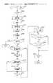
図1は、実施例1における撮影前情報を撮影した画像と共に表示画面上に再生した表示例を示す説明図、図2は、本発明に係る撮像装置としてのデジタルカメラのシステムの一構成例を示すブロック図、図3は、実施例1におけるクイックレビュー再生の処理手順例を示すフローチャート、図4は、実施例1における撮影準備の処理手順例を示すフローチャート、図5は、実施例2における撮影前後情報または撮影後情報を撮影した画像と共に表示画面上に再生した表示例を示す説明図、図6は、実施例2における撮影後処理の手順例を示すフローチャート、図7は、実施例3におけるプレイバック再生の処理手順例を示すフローチャート、図8は、実施例5における撮影前後情報を撮影した画像と共に表示画面上に再生した表示例を示す説明図、図9は、実施例6における撮影前後情報とその詳細情報(撮影前後詳細情報)を撮影した画像と共に表示画面上に再生した表示例を示す説明図である。
【0023】
以下、添付図面を参照して本発明の好適な実施例を詳細に説明する。
【0024】
図2は、本発明に係る撮像装置としてのデジタルカメラのシステムの一構成例を示すブロック図である。
【0025】
同図中、201は図示していない被写体像を結像するレンズ、202はレンズ201からの入射光量を調節する絞り機構、203はレンズ201から絞り機構202を通って入射した光信号を電気信号に変換する撮像素子、204は撮像素子203により光電変換された信号をサンプリングしてゲインコントロールするCDS,AGC回路、205はCDS,AGC回路204から出力されるアナログ信号をデジタル信号に変換するアナログ/デジタル変換器(以降、A/D変換器と記述する)、210はA/D変換器205によりA/D変換された信号に対して、所定の処理を施すカメラ信号処理回路、230はカメラ信号処理回路210などの装置から出力されたデジタル信号をメモリ212などの他の装置へ転送するためのデータバス、211は本デジタルカメラ全体を制御するマイクロコンピュータ(以下、CPUと記述する)、231はCPU211から出力される制御信号を伝達するCPUバス、212はデータバス230から送られる画像データなどのデジタル信号等を一時的に記憶する記憶装置(以降、メモリと記述する)、209はAF(オートフォーカス)制御のために所定の処理を行うAF用信号処理回路、208はAF用信号処理回路209から出力される信号に基づいてAF制御を行うAF制御回路、207はレンズ201を駆動するフォーカスレンズ駆動回路、206はレンズ201の駆動源であるフォーカスレンズモータ、213はAF等の制御エリアを設定するための制御エリア設定回路、215はカメラ信号処理回路210やメモリ212などから出力された画像データの一部を拡大する画像拡大処理回路、216はメモリ212上に一時的に保存されている画像データを画像ファイルの形で保存するメモリカードやディスクなどの2次記憶装置、217はカメラ信号処理回路210から出力した生の画像データをJPEGなどの圧縮アルゴリズムを用いて圧縮、また、その逆の伸長を行う画像圧縮・伸長装置、218は圧縮された画像データに様々なヘッダ情報を付加して画像ファイルを作成する手段と、画像ファイルからヘッダ情報と画像データを取り出す手段を備えた画像ファイル作成・読出し装置、222はLCD表示装置224に出力する映像信号を保持するVRAM、223はVRAM222から出力されたデジタル信号をアナログ信号に変換するデジタル/アナログ変換器(以降、D/A変換器と記述する)、224はD/A変換器223から出力されるアナログ映像信号をユーザに対して表示するLCD表示装置、221は撮影時にカメラ信号処理回路210やメモリ212などから出力された、また再生時に画像ファイル作成・読出し装置218により読出されたヘッダ情報内にある撮影前や撮影後のカメラが判断した情報や撮影前後を比較して評価した情報を解析する撮影前後情報解析装置、214は撮影前後情報解析装置221により解析された情報をLCD表示装置224等の表示装置上に表示する処理を行う撮影前後情報表示装置。
【0026】
219は撮影前後情報表示装置214に表示する項目の情報量を、クイックレビュー再生時やプレイバック再生時のデフォルトの再生モードとして撮影者が予め入力するためのパラメータ設定入力装置、220は撮影前後情報表示装置214に表示する項目の情報量を、撮影中や撮影中のクイックレビュー再生中、またはプレイバック再生中に撮影者が手動で切替えたい場合に指示信号を入力するための撮影前後情報表示スイッチである。
【0027】
このように構成されたデジタルカメラにおいて、被写体からの光はレンズ201及び絞り機構202を通して撮像素子203に結像し、電気信号に変換されて出力される。該出力された電気信号はCDS,AGC回路204に入力されてサンプリングされ、且つゲインコントロールされた後、A/D変換器205に入力されてデジタル信号に変換される。該変換されたデジタル信号は、カメラ信号処理回路210に入力されて所定の処理が施された後、D/A変換器223に入力される。そして、このD/A変換器223にてアナログ信号に変換された信号は、LCD表示装置224等に出力される。この信号の流れはEVF(電子ビューファインダ)を構成する一般的なものである。
【0028】
次に、撮影した画像に様々な画像処理を行いJPEGなどの画像ファイルとして記録メディアに保存する流れについての一例を説明する。
【0029】
カメラ信号処理回路210から出力されたデジタルデータは、データバス230を介してメモリ212に保存された後、画像圧縮・伸長装置217により圧縮処理等の画像処理がなされ、撮影情報(Tv値、Av値、選択された測距枠)などの属性値と共に、撮影前後情報解析装置221から出力された撮影前や撮影後の情報や、撮影前後の情報を比較して評価した情報の属性が付加した画像ファイルが画像ファイル作成・読出し装置218により生成される。その後、再びデータバス230を介して画像ファイルはメモリカードやハードディスクなどの2次記憶装置216に送られ記憶される。
【0030】
次に、記録メディアに保存された画像ファイルから画像処理を行い、画像データを表示装置などに表示する流れについての一例を説明する。
【0031】
2次記憶装置216に保存されている画像ファイルは、画像圧縮・伸張装置217により伸張処理等の画像処理がなされ、最終的にVRAM222に転送され、LCD表示装置224に表示される。また、前記画像ファイルは画像ファイル作成・読出し装置218により画像ファイル内にあるヘッダ情報が抽出され、更に抽出したヘッダ情報から撮影前後情報解析装置221により撮影前や撮影後の情報や撮影前後情報を比較して評価した情報が抽出される。
【0032】
これら画像ファイルの画像データやヘッダ情報の各情報が各装置に処理される際は、データバス230を介してメモリ212上に配置されることを幾度か繰り返す。また、撮影前後情報表示装置214は、CPU211よりCPUバス231を介してパラメータ設定入力装置219や撮影前後情報表示スイッチ220により撮影前後情報解析装置221が抽出した情報を表示するかどうかのパラメータや指示を取得し、その指示に従った情報を、先に説明した画像データが転送されているVRAM222上に転送し、画像データと共にLCD表示装置224に表示する。但し、撮影前後情報表示装置214が表示する情報は、ユーザが見て、その時点でLCD表示装置224に表示されている画像データとの対応がつけば、必ずしも画像データと一緒に表示する必要はない。
【0033】
なお、本デジタルカメラにおける撮影時と再生時のデータの流れや制御の流れなどの詳細な動作は先に説明した通りであるので、これ以降での説明においては省略する。
【0034】
また、これ以降の説明においてのフローチャートによる処理手順は、説明した例に限定されるものではなく、本発明の結果を満たす限りいかなる手順の組み合わせも、複数処理を纏めることも、処理を細分化することも可能であり、また、各処理を個々に切り出して、ひとつの機能要素として単体として機能し、示している処理以外の処理と組み合わせて使用することも可能である。
【0035】
(実施例1)
以下、本発明の実施例1を図面およびフローチャートを参照して説明する。
【0036】
図1は、本発明の第1の実施例で実現される撮像装置の表示例を示しており、撮影時でのクイックレビュー再生を行っているか、もしくは再生時のプレイバック再生を行っている状態である。
【0037】
図1において、101は、LCD全体画面を示したものであり、102は主被写体である。103に示す内容は、撮影前のカメラが判断した情報を、ユーザが理解しやすいように簡略化して表示している。この撮影前情報103の例では、撮影前にカメラが露出や明るさを測定するセンサー等の測定結果により決定したシャッタースピードが遅いために、手ぶれを起こす可能性が高いことをカメラに付随するLED表示等によりユーザに警告をしていたが、そのまま撮影が続行された場合の例であり、クイックレビュー再生やプレイバック再生時に、撮影された画像は手ぶれ警告がなされたまま撮影されたという情報をユーザに通知している。但し、図1の撮影前情報103の内容は、ユーザがその内容を認識できるものであれば何でも良く、例えば絵のアイコンを表示したり、「手ぶれした可能性があります」等の説明の文章を表示してもよい。
【0038】
図3は、レリーズスイッチが押されてから、AE,AFなどの撮影準備を行い、実際の撮影を行った後に、クイックレビュー再生を表示するまでの概略の流れを示したフローチャートである。また、実際のカメラでは、撮影までのAE,AFなどの撮影準備の処理と、実際の撮影の処理とをレリーズスイッチの半押しと全押し等により分けていることが多いが、この例では一緒にしている。
【0039】
ステップS301では、クイックレビュー再生の設定がされている状態で、ユーザによりレリーズスイッチが押されると、このフローが開始される。ステップS302では、LCD表示がONの場合はそれをOFFにする。
【0040】
ステップS303では、AEやAF、測距枠の選択などの、撮影を行うのに必要となる準備(以降、撮影準備と呼ぶ)を行う。なお、撮影準備(ステップS303)に関しては、本発明での撮影前にカメラが判断した情報となり、本実施例中での次に詳しく説明する。
【0041】
ステップS304では、撮影準備(ステップS303)が完了すると実際の撮影を行う。
【0042】
ステップS317では、撮影(ステップS304)が完了すると撮影準備で得た値との変化を確かめるための後処理(以降、撮影後処理と呼ぶ)を行う。なお、撮影後処理(ステップS317)に関しては、本発明での撮影後にカメラが判断した情報となり、実施例2の説明で詳しく説明する。
【0043】
ステップS305では、撮影(ステップS304)での画像に対して画像処理を行い、その画像に対する情報をヘッダ(付帯)情報を付加したJPEGなどの画像ファイルを作成する。
【0044】
ステップS306では、作成した画像ファイルを記録メディアなどに保存する。
【0045】
ステップS307では、クイックレビュー機能が有効な設定になっているかを確認し、クイックレビューを行わない設定では本撮影シーケンスを終了し、クイックレビューを行う設定ではステップS308へ進む。
【0046】
ステップS308では、撮影前後情報の表示機能が有効な設定になっているかを確認し、有効な設定ではステップS309に進み、無効な設定ではステップS311へ進む。
【0047】
ステップS309では、撮影準備(ステップS303)と撮影後処理(ステップS317)の処理中に収集された撮影前情報と撮影後情報を解析する。ステップS309で解析する情報は、図1で示した撮影前情報103の例では、撮影準備(ステップS303)時に得られたシャッタースピード、または、そのシャッタースピードから判断すると手ぶれした可能性があるという情報、または、手ぶれ警告をユーザに通知していたが、そのままレリーズボタンが押されたという情報等である。
【0048】
ステップS318では、撮影前後情報の詳細表示機能が有効な設定になっているかを確認し、有効な設定ではステップS310へ進み、無効な設定ではステップS311へ進む。
【0049】
ステップS310では、撮影前後情報解析(ステップS309)での情報に、各処理内で得ているその他の撮影情報を加えて、更に詳細に評価した情報(以下、撮影前後詳細情報と呼ぶ)を生成する。
【0050】
ステップS311では、撮影画像データと共に、撮影前後情報解析(ステップS309)と撮影前後情報詳細解析(ステップS310)で得られた情報をLCD画面上に表示する処理(ファインダ表示)を行う。
【0051】
ステップS308において、撮影前後情報表示機能が無効の場合、ステップS309、ステップS310は実行せずに、ステップS311を実行する。すなわち、撮影した画像のみを、そのままファインダ表示する。
【0052】
ステップS312では、ファインダ表示(ステップS311)が開始された後、クイックレビュータイマが起動される。これは、クイックレビューによるファインダ表示を一定時間だけ行うために用いられる仕組みである。
【0053】
ステップS313では、クイックレビューを中止するような命令(電源OFF、SW1 ONなど)が届いたかどうかの確認を行う。中止命令が届いていない場合はステップS314に進み、届いている場合はステップS315へ進む。
【0054】
ステップS314では、起動したクイックレビュータイマ(ステップS312)が終了したかどうかの確認を行う。タイマが終了していない場合は、ステップS313に戻り、以下同様なステップを繰り返す。クイックレビュータイマが終了した場合は、ステップS315に進む。
【0055】
ステップS315では、LCD表示をOFFにして、このシーケンスを終了する。
【0056】
なお、画像処理(ステップS305)で作成され、保存処理(ステップS306)で保存する画像ファイルのファイルフォーマットは、画像データと共にその画像に関する情報としてヘッダ(付帯)情報を保存でき、本発明で定義している情報をヘッダ情報の一部として扱えるものであれば、ファイルフォーマットの種類は何でもよい。例えば、現在最も多くのデジタルカメラで採用し普及しているExif規格に準拠するJPEGファイルフォーマットや、TIFFファイルフォーマットやFlashPixファイルフォーマットやCIFFファイルフォーマット、また独自のファイルフォーマットなど、その他、多くのファイルフォーマットがデジタルカメラで採用されている。
【0057】
また、今後も新しいファイルフォーマットをデジタルカメラは扱うことになることが予想される。しかし、これらのファイルフォーマットでは、一般的に画像ファイルの中に、画像データと共にその画像に対するヘッダ(付帯)情報を一緒に格納することができるという共通性を持つ。更に、ほとんどのファイルフォーマットにおいて、このヘッダ情報には、そのファイルフォーマットで定義された情報の他に独自に情報を定義することができるように規定されている。例えば、Exif規格の仕様で定義されているヘッダ(付帯)情報としては、撮影日時や画像サイズ等の画像関連の情報と、露出時間やシャッタースピード等のカメラに特化した情報等があり、また独自に情報を定義することができる領域としてメーカーノートという規定がされている。
【0058】
本発明で定義している撮影前情報、撮影後情報、撮影前後情報(本文中の撮影前後詳細情報を含む)は、ファイルフォーマットのヘッダ(付帯)情報として画像データと共に画像ファイルに保存される。但し、本発明で定義している情報は、先に述べたファイルフォーマットの仕様で定義されている情報を格納する領域でも、ファイルフォーマットの仕様で独自に定義しても差し支えない領域へ情報を格納しても構わない。
【0059】
図4は、図3の撮影準備(S303)の流れを詳細に説明したフローチャートである。
【0060】
ステップS401で撮影準備が開始されると、ステップS402では、測光を行う。ステップS403では、測光(ステップS402)での測光値を基に露出演算を行う。ステップS404では、自動測距枠の選択モードが有効かどうかの判断を行い、有効な場合にはステップS405へ進み、無効な場合にはステップS406へ進む。
【0061】
ステップS405では、最近焦点位置検出を行った後、ステップS408へ進む。これは、最も近い位置にある被写体の焦点位置を検出するものである。
【0062】
ステップS406では、視線検出モードが有効かどうかの判断を行い、有効な場合にはステップS407へ進み、無効な場合には、予めユーザが選択したAF測距枠が選択され、ステップ408へ進む。
【0063】
ステップS407では、視線位置検出を行い、ユーザの視線による測距枠の選択を行う。
【0064】
但し、ステップS406、S407は視線検出による、AF測距枠選択機能を有するカメラの手順を表したもので、該機能を持たないカメラは省略される。
【0065】
ステップS408では、ステップS405での自動選択、ステップS407での視線選択、それ以外でのユーザ設定のいずれかの方法で選択されたAF測距枠を使ってAF動作を行わせるために、AF制御エリア設定を行う。
【0066】
ステップS409では、設定されたエリアを用いて焦点検出を行う。
【0067】
ステップS410では、焦点検出に成功したかどうかの判定を行い、成功した場合には、ステップS411へ進み、失敗した場合にはこのシーケンスを終了する。
【0068】
ステップS411では、フォーカスレンズを合焦位置まで駆動させる。
【0069】
ステップS412では、本撮影準備での各処理で得られた測定データや設定データや、それらデータを基に算出された値や判断がなされた結果を、撮影前情報としてメモリに記憶し保存する。
【0070】
これら撮影準備で得られる情報の例は幾通りも考えられる。その具体例として、図1の例では、ステップS402とステップS403の結果、決定されたシャッタースピードの情報を、または、決定されたシャッタースピードが遅いためにユーザに手ぶれ警告をしたという情報を、ステップS412で保存しておき、のちに(図3のフローチャートの処理で)、その情報を利用した結果を示したものである。
【0071】
その他、ユーザからの入力として選択された視線位置やAF測距枠やフラッシュ発光設定の有無や撮影モード等、また各処理による判断や算出された結果としてAF制御エリアや焦点検出したときの測定値やレンズ駆動量に換算されたデフォーカス量や被写体との距離やフラッシュの発光強度等、各種撮影情報を撮影前情報として保存しておく。
【0072】
以上のように、実施例1の撮像装置によれば、撮影前のカメラが判断した情報として、シャッタースピードが遅く設定されたユーザに手ぶれ警告を通知していた、等の撮影前の情報を記録する手段と、撮影後のクイックレビュー再生時に撮影画像と共に、手ぶれ警告があった画像である等の記録した撮影前の情報を表示する手段を有することにより、撮影後にLCD画面上では綺麗に見えている撮影画像は、手ぶれ警告がされたまま撮影された画像で、実際には手ぶれしている可能性がある等の状況をユーザは容易に判断することができる。
【0073】
(実施例2)
以下、本発明の実施例2を図面およびフローチャートを参照して説明する。
【0074】
図5は、本発明の第2の実施例で実現される撮像装置を示しており、撮影時でのクイックレビュー再生を行っているか、もしくは再生時のプレイバック再生を行っている状態であることは実施例1と同じである。
【0075】
図5において、501は、LCD全体画面を示したものであり、502は主被写体である。503に示す内容は、撮影前のカメラが判断した情報を基に撮影後のカメラが判断した情報と比較して評価した結果を、ユーザが理解しやすいように簡略化して表示している。この撮影前後情報503の例では、撮影準備(ステップS303)の時点での焦点検出で得た値と、撮影後にカメラが撮影準備時と同じ条件で再度焦点検出を行って得た値を比較した結果、ある基準以上の差が撮影前と撮影後の値にあり、総合的に判断すると撮影の瞬間に被写体が動いていた可能性が高いという例であり、クイックレビュー再生やプレイバック再生時に、撮影された画像は撮影の瞬間に被写体が動いた可能性が高いという情報をユーザに通知している。但し、図5の撮影前後情報503の内容は、ユーザがその内容を認識できるものであれば何でも良く、例えば絵のアイコンを表示するか、または「被写体が動いた可能性があります」等の説明の文章を表示してもよい。
【0076】
レリーズスイッチが押されてからの処理については実施例1での図3の説明と同じである。但し、ステップS309で解析する情報は、図5で示した撮影前後情報503の例では、撮影準備(ステップS303)と撮影後処理(ステップS317)の処理中での焦点検出で得た値、またはそれを加工した値である。
【0077】
図6は、図3の撮影後処理(ステップS317)の流れを詳細に説明したフローチャートである。撮影後処理が開始されると(ステップS601)、撮影準備(ステップS303)で行われた処理とは別に、ステップS602では、再度、測光を行う。ステップS603では、測光(ステップS602)での測光値を基に露出演算を行う。
【0078】
ステップS604では、ステップS412で保存されている撮影前情報であるAF測距枠、またはAF制御エリアの情報を使って、同じ条件で再度焦点検出を行う。
【0079】
ステップS605では、本撮影後処理での各処理で得られ測定データや、それらデータを基に算出された値や判断がなされた結果を、撮影後情報としてメモリに記憶する。
【0080】
これら撮影後処理で得られる情報の例は幾通りも考えられる。その具体例として図4の例では、ステップS604の結果、被写体との距離等の情報をステップS605で保存しておき、のちに(図3のフローチャートの処理で)、その情報を利用した結果を示したものである。但し、ステップS605で保存される撮影後情報は、ステップS412にて保存した撮影前情報と変化が見られない場合には、撮影前情報と撮影後情報が同じだと判断して保存しなくてもよいし、または、情報としては同じだが、取得したタイミングが違うことから保存してもよい。
【0081】
以上のように、実施例2の撮像装置によれば、撮影前にカメラが判断した情報である被写体との距離と、撮影後にカメラが判断した情報である被写体との距離が、ある設定されている基準と違っているという解析をする手段と、その情報を記憶する手段と、撮影後のクイックレビュー時に撮影画像と共に解析した結果の被写体が動いた可能性があった画像だということを表示する手段を有することにより、撮影後にLCD画面上では綺麗に見えている撮影画像は、撮影の瞬間に被写体が動いて撮影された画像で、実際には被写体がぶれて写っている可能性があることをユーザは容易に確認することができる。
【0082】
また実施例2の撮像装置によれば、撮影後情報だけの情報で判断し、撮影前情報は、全く保存していない場合を想定する。例えば、撮影後に算出したシャッタースピードは遅いため、撮影前に設定されたシャッタースピードも遅かった可能性があり手ぶれもしている可能性がある、または撮影後に焦点検出を数回した結果、被写体との距離が変化し続けているので、撮影した瞬間も動いていた可能性がある等、撮影後にカメラが判断した情報を保存する手段と、その情報を表示する手段を有することにより、撮影後にLCD画面上では綺麗に見えている撮影画像は、撮影者が意図しない画像であるかもしれないということを、ユーザに容易に通知することができる。
【0083】
(実施例3)
以下、本発明の実施例3を説明する。
【0084】
本発明の実施例1と実施例2で示した事項に加え、図3における保存処理(ステップS306)において、画像ファイル生成・読出し装置218を用い、撮影準備(ステップS303)内で得た撮影前情報(ステップS412)と撮影後処理(ステップS317)内で得た撮影後情報(ステップS605)と、それら情報を撮影前後情報解析(第1の解析手段、ステップS309)、もしくは撮影前後情報詳細解析(第2の解析手段、ステップS310)にて得た情報を画像ファイル内のヘッダ情報として保存する。
【0085】
図7は、実施例1のクイックレビュー再生時の拡大表示に対して、撮影後のプレイバック再生時に画像ファイル内のヘッダ情報から撮影前情報と撮影後情報を解析して表示を行う手順を示したものである。
【0086】
なお、図7のフローチャートは記録メディアの保存されている1つの画像ファイルを何らかの方法で選択して表示する手順を示したものである。
【0087】
ステップS702では、LCD表示がONされる。ステップS703では、記録メディアから表示対象となる画像ファイルを選択する。ステップS704では、選択された画像ファイルのヘッダ情報を読み出す。
【0088】
ステップS705では、該ファイルの画像データを読出し、伸長処理を行う。
【0089】
ステップS706では、撮影前後情報表示機能が有効な設定になっているかを確認し、有効な設定では、ステップS707に進み、無効な設定ではステップS710へ進む。
【0090】
ステップS707では、ヘッダ情報読み出し(ステップS704)から撮影前情報と撮影後情報を抽出し解析する。
【0091】
ステップS708では、撮影前後情報の詳細表示機能が有効な設定になっているかを確認し、有効な設定ではステップS709へ進み、無効な設定ではステップS710へ進む。
【0092】
ステップS709では、撮影前後情報解析(ステップS707)での情報に、ヘッダ情報読み出し(ステップS704)で得ているその他の撮影情報を加えて、更に、第2の解析手段で詳細に評価した情報(以下、撮影前後詳細情報と呼ぶ)を生成する。
【0093】
ステップS710では、撮影画像データと共に、撮影前後情報解析(ステップS707)と撮影前後情報詳細解析(ステップS709)で得られた情報をLCD画面上に表示する処理(ファインダ表示)を行う。
【0094】
ステップS706において、撮影前後情報表示機能が無効の場合、ステップS707、ステップS708は実行せずに、ステップS710を実行する。すなわち、撮影した画像のみを、そのままファインダ表示する。
【0095】
以上のように、実施例3の撮像装置によれば、記録メディアの保存された画像ファイルをプレイバック再生する場合に、画像ファイルに保存されている撮影前情報と撮影後情報と撮影前後情報を解析する手段と、それら情報の1つ以上の組合わせた情報をLCD画面上の画像データと共に表示する手段を有することにより、LCD画面上では綺麗に見えている画像ファイルは、撮影者が意図しない画像であるかもしれないということを、ユーザに容易に通知することができる。
【0096】
(実施例4)
本発明の実施例1、2では、撮影した画像または、記録メディアから選択した画像の撮影前後情報を表示する機能を自動的に呼び出す方法を実現した実施例であり、具体的にはカメラのデフォルトの設定であったり、図1におけるパラメータ設定入力装置219により、ユーザが事前に撮影前後情報を表示する情報量を設定していた例である。
【0097】
本実施例4では、撮影前後情報を表示する機能を呼び出す方法を、いつでもユーザの指示により行える様にしたものであり、具体的には図2における、撮影前後情報表示スイッチ220をユーザがONした場合にのみ該機能を呼び出す様にしたものである。ユーザは、撮影中、撮影中のクイックレビュー再生中、プレイバック再生中など、いつでも撮影前後情報を表示する機能を呼び出すことができる。
【0098】
撮影前後情報表示スイッチ220の例としては、複数のスイッチでも1つのスイッチでもよく、複数のスイッチの場合は1つ以上のスイッチが押された組合わせや、1つのスイッチの場合は押された回数による撮影前後情報の表示する情報量を切替えていくことが可能である。例えば、1つのスイッチの場合で、OFFの状態から1回押すと撮影前情報を表示し、もう一度押すと撮影後情報の表示に切り替わり、もう一度押すと撮影前後情報、もう一度押すと撮影前後情報の詳細な内容(撮影前後詳細情報)、もう一度押すと撮影前後情報の表示機能がOFFになる等の実現が可能である。
【0099】
(実施例5)
本発明の実施例1、2において、図1の撮影前情報103と、図5の撮影前後情報503とで、同じ表示形態で表示されており、ユーザにとって何の情報を基に表示されているのかが判断しにくかったが、撮影前情報と撮影後情報と撮影前後情報の表示形態を変化させることで、ユーザが容易に何の情報を基に表示されている情報なのか判断することできる。
【0100】
例えば、図8の撮影前情報803の表示形態(図1の例では四角)と、撮影前後情報804の表示形態を円形(図5の例では四角)として区別し、ユーザに対して撮影前の警告の情報なのか、撮影前と撮影後の評価した結果の情報なのかを視覚的にわかりやすく表示することも可能である。
【0101】
(実施例6)
本発明の実施例1、2、3、4において、図3の撮影前後情報詳細解析(S310)、図7の撮影前後情報詳細解析(S709)などで説明した、撮影前情報と撮影後情報を比較して評価した結果に対し、その他の撮影情報を加えて、更に詳細に評価した情報を表示する例を説明する。
【0102】
図9の撮影前後詳細情報905(正確には撮影前のみの詳細情報)は、撮影前情報903を詳細に示すために、実際のシャッタースピードの値やストロボを使用したかどうかの情報を画像ファイルのヘッダ情報から取得し、それをユーザが容易に判断できるような説明文章を更に追加表示した例である。撮影前後詳細情報906は、撮影前後情報904を詳細に示すために、撮影前情報である撮影前の被写体との距離と、撮影後情報である撮影後の被写体との距離を画像ファイルのヘッダ情報から取得し、ユーザが容易に判断できるような説明文章を追加表示した例である。こうすることで、ユーザは容易に、LCD画面に表示されている画像が手ぶれしている可能性や被写体が動いたことによりピントが合っていない可能性があることを判断できると共に、何故手ぶれしてしまった可能性があるのか、どの程度被写体が動いてピントがボケてしまった可能性があるのか、その理由を知ることができる。
【0103】
また、クイックレビュー再生時なら、ユーザは、これら撮影前後情報の903、904、905、906を見ることによって、今撮影した画像が意図する画像でないのであれば、撮影前後詳細情報905、906に表示された説明から新たな撮影条件を判断し、その新たな撮影条件で次に撮影を試みる等の対策を即座に実行することが可能になる。
【0104】
尚、解析手段を第1の解析手段と第2の解析手段と、分けて説明したが、特に分けずに、一つの解析手段を使用しても、機能的に問題なければ良いことは勿論である。
【0105】
【発明の効果】
以上説明したように、本発明によれば、撮影した画像を評価するための情報を画像に関連付けて記録することによって、撮影した画像の良し悪しを判断する材料とすることができる。
【図面の簡単な説明】
【図1】 実施例1における撮影前情報を撮影した画像と共に表示画面上に再生した表示例を示す説明図
【図2】 本発明に係る撮像装置としてのデジタルカメラのシステムの一構成例を示すブロック図
【図3】 実施例1におけるクイックレビュー再生の処理手順例を示すフローチャート
【図4】 実施例1における撮影準備の処理手順例を示すフローチャート
【図5】 実施例2における撮影前後情報または撮影後情報を撮影した画像と共に表示画面上に再生した表示例を示す説明図
【図6】 実施例2における撮影後処理の手順例を示すフローチャート
【図7】 実施例3におけるプレイバック再生の処理手順例を示すフローチャート
【図8】 実施例5における撮影前後情報を撮影した画像と共に表示画面上に再生した表示例を示す説明図
【図9】 実施例6における撮影前後情報とその詳細情報(撮影前後詳細情報)を撮影した画像と共に表示画面上に再生した表示例を示す説明図
【符号の説明】
101 LCD画面
102 主被写体
103 撮影前情報(撮影前後情報)
201 撮影レンズ
202 絞り装置
203 撮像素子
204 CDS,AGC回路
205 A/D変換器
206 フォーカスレンズモータ
207 フォーカスレンズ駆動回路
208 AF制御回路
209 AF用信号処理回路
210 カメラ信号処理回路
211 CPU
212 メモリ
213 制御エリア設定回路
214 撮影前後情報表示装置
215 画像拡大処理回路
216 2次記憶装置
217 画像圧縮・伸長装置
218 画像ファイル作成・読出し装置
219 パラメータ設定入力装置
220 撮影前後情報表示スイッチ
221 撮影前後情報解析装置
222 VRAM
223 D/A変換器
224 LCD表示装置
230 データバス
231 CPUバス[0001]
BACKGROUND OF THE INVENTION
The present invention is applied to, for example, a system that stores an image captured by an imaging device such as a digital camera as an image file. In particular, image data stored in a memory that is a temporary storage medium such as a digital camera is displayed on an LCD. Imaging device having means for displaying on display screenIn placeRelated.
[0002]
[Prior art]
In recent years, with the development of digital technology, digital cameras that process captured image information electronically have become widespread. The subject luminous flux that has passed through the photographic lens reaches a solid-state image sensor (CCD, etc.), converts the subject image into an electrical signal, outputs it as a video signal, and the captured image is subjected to various conversion processes in the image processing circuit. In general, those having a reproduction function of displaying image data on a liquid crystal monitor (LCD) built in the digital camera at the same time as being stored as an image file in a storage medium such as a memory card.
[0003]
The purpose of displaying an image on a display screen such as an LCD is to allow quick review playback that is displayed for the purpose of confirming the image data taken immediately after shooting, and the user selectively operates an image file that has already been shot. There is playback playback that displays image data in an image file. In the quick review reproduction, after the image processing after shooting, the entire image data is automatically displayed on the LCD for a certain period of time with the size of the display screen such as the LCD. In playback reproduction, there is a camera having a function of selecting image files one after another and reproducing selected image data and a function of displaying a plurality of thumbnail image data on an LCD.
[0004]
In addition, recent digital cameras are lightweight and miniaturized, so that users can easily carry them, and are very portable. However, on the other hand, in the reproduction of image data, the display screen of the LCD for confirming the appearance of the photographed image is very small (there is also a factor of cost reduction). Therefore, if you look at the image displayed on the LCD in the normal size, it looks fine on the LCD, but if you import the image file onto the personal computer and check it, the focus will be lost. The captured image may not be the image intended by the user, such as being out of focus, shaking, or low brightness.
[0005]
However, since the user looked beautiful on the LCD, he did not take measures such as re-taking the subject again, and when he confirmed it later with a personal computer, the image was not what he intended. You will notice.
[0006]
On the other hand, because of the ease of digital cameras in recent years, the majority of digital camera owners are users who are not familiar with cameras and images. For such a general user, when the shutter speed is slow, a camera shake warning is issued from the camera before shooting, or while the subject is moving, without worrying too much, Depending on how you do it, you often shoot without being aware of it.
[0007]
However, at the time of playback playback, it is difficult to remember shooting information such as a camera shake warning before each shooting or a subject moving at the moment of shooting in many image files. Therefore, if the image data of the image file is reproduced in the normal size (displaying the entire image data) on the LCD, it is optimal for the next shooting without knowing what the condition was bad. In many cases, the setting cannot be changed to the condition.
[0008]
In order to solve such a problem, there is a camera having a function of enlarging and displaying a partial area of image data displayed on a display screen such as an LCD. The user can enlarge and display the image data displayed in the normal size on the LCD during quick review or playback by operating the buttons, etc. It is possible to check the appearance of the captured image.
[0009]
[Problems to be solved by the invention]
However, even if the captured image can be confirmed by enlarging and displaying the image data as in the conventional example described above, a camera shake warning or subject has been issued before the captured image is captured. It is not possible to confirm the shooting information such as when the camera moves. Further, operations for enlarging image data and operations for scrolling up, down, left and right are very troublesome operations with few buttons attached to a small digital camera, and there are problems such as extremely high battery consumption. Further, there is a problem that a general user does not fully understand how to set a shooting condition specifically to capture a better image than the currently displayed image.
[0010]
The present invention has been made in view of the above-described circumstances. In a system for storing images of an imaging device such as a digital camera, when a captured image is reproduced or a stored image file is reproduced, By displaying on the display screen, together with the playback image data, information that is determined by the camera after shooting and information obtained by comparing one or more of the information that has been compared and evaluated. An imaging device capable of suitably taking and playing back such as a digital camera that can easily determine the conditionPlaceThe purpose is to provide.
[0011]
[Means for Solving the Problems]
This invention can solve the said subject by providing the following structure.
[0012]
Imaging means for taking an image;
Shooting information detection means for detecting shooting information when the imaging means takes an image;
Before taking the image, the image taken by the imaging meansBy the photographing information detection meansAn image pickup apparatus comprising: recording means for associating and recording detected pre-shooting information and post-shooting information detected by the shooting information detecting means after shooting of the image.
[0021]
DETAILED DESCRIPTION OF THE INVENTION
Hereinafter, the imaging device according to the present invention.SetAn embodiment will be described.
[0022]
FIG. 1 is an explanatory diagram illustrating a display example reproduced on a display screen together with a photographed image of pre-shooting information in the first embodiment, and FIG. 2 is a configuration example of a system of a digital camera as an imaging apparatus according to the present invention. FIG. 3 is a flowchart showing an example of a quick review reproduction processing procedure in the first embodiment, FIG. 4 is a flowchart showing an example of a shooting preparation processing procedure in the first embodiment, and FIG. 5 is a shooting procedure in the second embodiment. FIG. 6 is an explanatory diagram showing a display example reproduced on the display screen together with the captured image of the before / after information or post-shooting information, FIG. 6 is a flowchart showing a procedure example of post-shooting processing in the second embodiment, and FIG. FIG. 8 is a flowchart showing an example of a playback playback processing procedure, and FIG. 8 is a diagram showing a display example in which information before and after shooting in Example 5 is played back together with a shot image on a display screen. Figure 9 is an explanatory diagram showing a display example of reproducing on a display screen shot before and after the information along with the detailed information image obtained by photographing a (photographic details longitudinal) in Example 6.
[0023]
Hereinafter, preferred embodiments of the present invention will be described in detail with reference to the accompanying drawings.
[0024]
FIG. 2 is a block diagram illustrating a configuration example of a system of a digital camera as an imaging apparatus according to the present invention.
[0025]
In the figure, 201 is a lens that forms a subject image (not shown), 202 is a diaphragm mechanism that adjusts the amount of incident light from the
[0026]
219 is a parameter setting input device for the photographer to input the information amount of items displayed on the pre- and post-shooting
[0027]
In the digital camera configured as described above, light from the subject forms an image on the
[0028]
Next, an example of the flow of performing various image processing on a photographed image and saving it in a recording medium as an image file such as JPEG will be described.
[0029]
The digital data output from the camera
[0030]
Next, an example of a flow of performing image processing from an image file saved on a recording medium and displaying image data on a display device or the like will be described.
[0031]
The image file stored in the
[0032]
When each piece of information of the image data and header information of these image files is processed by each device, the arrangement of the data on the
[0033]
Note that detailed operations such as data flow and control flow at the time of shooting and playback in the digital camera are as described above, and will not be described in the following description.
[0034]
In addition, the processing procedure according to the flowchart in the following description is not limited to the example described, and any combination of procedures, a plurality of processings can be combined, and the processing can be subdivided as long as the result of the present invention is satisfied. It is also possible to cut out each process individually, function as a single functional element, and use it in combination with processes other than those shown.
[0035]
Example 1
Hereinafter, the present inventionExample 1Will be described with reference to the drawings and flowcharts.
[0036]
FIG. 1 shows a display example of the imaging apparatus realized in the first embodiment of the present invention, in a state where quick review playback is performed at the time of shooting or playback playback is performed at the time of playback. It is.
[0037]
In FIG. 1,
[0038]
FIG. 3 is a flowchart showing a schematic flow from when the release switch is pressed to when shooting preparations such as AE and AF are performed, and after actual shooting is performed, quick review playback is displayed. Also, in an actual camera, the shooting preparation processing such as AE and AF until shooting and the actual shooting processing are often divided by half-pressing the release switch and full-pressing, etc. I have to.
[0039]
In step S301, when the user presses the release switch in a state where quick review playback is set, this flow is started. In step S302, if the LCD display is ON, it is turned OFF.
[0040]
In step S303, preparations required for shooting (hereinafter referred to as shooting preparation) such as AE, AF, and selection of a distance measurement frame are performed. The shooting preparation (step S303) is information determined by the camera before shooting in the present invention, and will be described in detail next in the present embodiment.
[0041]
In step S304, actual shooting is performed upon completion of shooting preparation (step S303).
[0042]
In step S317, after the shooting (step S304) is completed, a post-process (hereinafter referred to as a post-shooting process) is performed to confirm a change from the value obtained in the shooting preparation. The post-shooting process (step S317) is information determined by the camera after shooting in the present invention, and will be described in detail in the description of the second embodiment.
[0043]
In step S305, image processing is performed on the image captured (step S304), and an image file such as JPEG is created by adding header (accompanying) information to the information about the image.
[0044]
In step S306, the created image file is stored in a recording medium or the like.
[0045]
In step S307, it is confirmed whether the quick review function is enabled. If the setting is not performed, the actual shooting sequence is terminated.AndIn the setting for performing the quick review, the process proceeds to step S308.
[0046]
In step S308, it is confirmed whether or not the display function for pre- and post-shooting information is set to be valid. If the setting is valid, the process proceeds to step S309. If the setting is invalid, the process proceeds to step S311.
[0047]
In step S309, pre-shooting information and post-shooting information collected during the shooting preparation (step S303) and post-shooting processing (step S317) are analyzed. In the example of the
[0048]
In step S318, it is confirmed whether or not the detailed display function of the pre- and post-photographing information is valid. If the setting is valid, the process proceeds to step S310. If the setting is invalid, the process proceeds to step S311.
[0049]
In step S310, the information obtained before and after the photographing (step S309) is added to the other photographing information obtained in each process to generate information evaluated in more detail (hereinafter referred to as detailed information before and after photographing). To do.
[0050]
In step S311, processing (viewfinder display) is performed for displaying the information obtained in the pre- and post-shooting information analysis (step S309) and the detailed pre- and post-shooting information analysis (step S310) on the LCD screen together with the captured image data.
[0051]
If it is determined in step S308 that the pre-photographing information display function is invalid, step S309 and step S310 are not executed, but step S311 is executed. That is, only the photographed image is displayed as it is in the viewfinder.
[0052]
In step S312, after the finder display (step S311) is started, a quick review timer is started. This is a mechanism used for performing a finder display by quick review only for a certain period of time.
[0053]
In step S313, it is confirmed whether or not a command for stopping the quick review (power OFF, SW1 ON, etc.) has been received. If the cancel instruction has not arrived, the process proceeds to step S314, and if it has arrived, the process proceeds to step S315.
[0054]
In step S314, it is confirmed whether or not the activated quick review timer (step S312) has ended. If the timer has not expired, the process returns to step S313, and thereafter the same steps are repeated. If the quick review timer has expired, the process proceeds to step S315.
[0055]
In step S315, the LCD display is turned off and this sequence is terminated.
[0056]
Note that the file format of the image file created in the image processing (step S305) and saved in the saving processing (step S306) can store header (accompanying) information as information about the image together with the image data, and is defined in the present invention. Any type of file format can be used as long as the information can be handled as part of the header information. For example, many other file formats such as the JPEG file format that conforms to the Exif standard, which is currently adopted by most digital cameras, the TIFF file format, the FlashPix file format, the CIFF file format, and its own file format. Is used in digital cameras.
[0057]
In addition, digital cameras are expected to handle new file formats in the future. However, these file formats have a common feature that, in general, header (accompanying) information for the image can be stored together with the image data in the image file. Further, in most file formats, this header information is defined so that information can be uniquely defined in addition to the information defined in the file format. For example, header (ancillary) information defined in the specifications of the Exif standard includes image-related information such as shooting date and time and image size, and information specific to the camera such as exposure time and shutter speed. A maker note is defined as an area where information can be defined independently.
[0058]
The pre-photographing information, post-photographing information, and pre- and post-photographing information (including pre- and post-photographing detailed information in the text) defined in the present invention are stored in the image file together with the image data as file format header information. However, the information defined in the present invention is stored in an area where the information defined in the file format specification described above can be stored, or in an area where it can be defined independently in the file format specification. It doesn't matter.
[0059]
FIG. 4 is a flowchart illustrating in detail the flow of shooting preparation (S303) in FIG.
[0060]
When shooting preparation is started in step S401, photometry is performed in step S402. In step S403, an exposure calculation is performed based on the photometric value in photometry (step S402). In step S404, it is determined whether or not the automatic ranging frame selection mode is valid. If valid, the process proceeds to step S405, and if invalid, the process proceeds to step S406.
[0061]
In step S405, the focus position is detected most recently, and then the process proceeds to step S408. This is to detect the focal position of the subject at the closest position.
[0062]
In step S406, it is determined whether or not the line-of-sight detection mode is valid. If valid, the process proceeds to step S407. If invalid, the AF distance measurement frame selected in advance by the user is selected, and the process proceeds to step 408.
[0063]
In step S407, the line-of-sight position is detected, and a distance measurement frame is selected based on the line of sight of the user.
[0064]
However, steps S406 and S407 represent the procedure of a camera having an AF range selection function based on line-of-sight detection, and cameras that do not have this function are omitted.
[0065]
In step S408, AF control is performed in order to perform the AF operation using the AF distance measurement frame selected by any one of the automatic selection in step S405, the line-of-sight selection in step S407, and the user setting other than that. Set the area.
[0066]
In step S409, focus detection is performed using the set area.
[0067]
In step S410, it is determined whether or not focus detection is successful. If successful, the process proceeds to step S411, and if unsuccessful, the sequence is terminated.
[0068]
In step S411, the focus lens is driven to the in-focus position.
[0069]
In step S412, the measurement data and setting data obtained in each process in the actual photographing preparation, the values calculated based on the data, and the results of the determination are stored and stored in the memory as pre-photographing information.
[0070]
There are many examples of information that can be obtained in preparation for shooting. As a specific example, in the example of FIG. 1, information on the shutter speed determined as a result of step S402 and step S403, or information that the user has been warned to shake due to a slow shutter speed is obtained. The result of using the information stored in S412 and later (in the process of the flowchart in FIG. 3) is shown.
[0071]
In addition, the line-of-sight position selected as an input from the user, the AF distance measurement frame, the presence / absence of flash emission settings, the shooting mode, etc., and the measured values when the AF control area and focus are detected as a result of judgment and calculation by each process In addition, various pieces of shooting information such as a defocus amount converted into a lens driving amount, a distance from a subject, a flash emission intensity, and the like are stored as pre-shooting information.
[0072]
As aboveExample 1According to the imaging apparatus, as information determined by the camera before shooting, a means for recording information before shooting such as notifying a camera shake warning to a user whose shutter speed is set slow, and a quick review after shooting By having a means to display recorded pre-shooting information such as a camera shake warning image along with the shot image during playback, a camera shake warning is given to the shot image that is clearly displayed on the LCD screen after shooting. The user can easily determine the situation such as the possibility that the image is actually shaken with the image taken as it is.
[0073]
(Example 2)
Hereinafter, the present inventionExample 2With reference to the drawings and flowchartsThe
[0074]
FIG. 5 shows an image pickup apparatus realized in the second embodiment of the present invention, in a state where quick review playback is performed at the time of shooting or playback playback is performed at the time of playback. Is the same as in Example 1.
[0075]
In FIG. 5,
[0076]
The processing after the release switch is pressed is the same as the description of FIG. 3 in the first embodiment. However, in the example of the pre- and
[0077]
FIG. 6 is a flowchart illustrating in detail the flow of the post-shooting process (step S317) in FIG. When the post-shooting process is started (step S601), the photometry is performed again in step S602 separately from the process performed in the shooting preparation (step S303). In step S603, an exposure calculation is performed based on the photometric value in photometry (step S602).
[0078]
In step S604, focus detection is performed again under the same conditions using the information of the AF distance measurement frame or the AF control area that is the pre-shooting information stored in step S412.
[0079]
In step S605, the measurement data obtained in each process in the post-shooting process, the value calculated based on the data, and the result of the determination are stored in the memory as post-shooting information.
[0080]
Various examples of information obtained by these post-shooting processes are conceivable. As a specific example, in the example of FIG. 4, as a result of step S604, information such as the distance to the subject is stored in step S605, and later (in the process of the flowchart of FIG. 3), the result of using the information is displayed. It is shown. However, the post-shooting information stored in step S605 is not stored because it is determined that the pre-shooting information and the post-shooting information are the same if no change is seen with the pre-shooting information stored in step S412. Alternatively, it may be stored because the information is the same but the acquired timing is different.
[0081]
As aboveExample 2According to this imaging apparatus, the distance from the subject, which is information determined by the camera before shooting, and the distance from the subject, which is information determined by the camera after shooting, are different from a set reference. Means for storing the information, means for storing the information, and means for displaying that the subject as a result of analysis together with the photographed image during the quick review after photographing may have moved. The captured image that looks beautiful on the LCD screen is an image that was captured by moving the subject at the moment of shooting, and the user can easily confirm that the subject may actually be blurred. Can do.
[0082]
AlsoExample 2According to the imaging apparatus, it is assumed that the determination is based on only the information after shooting, and the information before shooting is not stored at all. For example, the shutter speed calculated after shooting is slow, so the shutter speed set before shooting may have been slow and there may be camera shake, or the result of focus detection several times after shooting, Since the distance keeps changing, there is a possibility of moving at the moment of shooting. For example, it has means for storing information judged by the camera after shooting, and means for displaying the information. It is possible to easily notify the user that the photographed image that looks beautiful above may be an image that is not intended by the photographer.
[0083]
(Example 3)
Hereinafter, the present inventionExample 3Will be explained.
[0084]
In addition to the matters shown in the first and second embodiments of the present invention, in the storage process (step S306) in FIG. 3, the image file generating /
[0085]
FIG. 7 shows a procedure for analyzing and displaying the pre-shooting information and post-shooting information from the header information in the image file during playback playback after shooting, with respect to the enlarged display during quick review playback of the first embodiment. It is a thing.
[0086]
Note that the flowchart of FIG. 7 shows a procedure for selecting and displaying one image file stored in the recording medium by some method.
[0087]
In step S702, the LCD display is turned on. In step S703, an image file to be displayed is selected from the recording medium. In step S704, the header information of the selected image file is read.
[0088]
In step S705, the image data of the file is read and decompressed.
[0089]
In step S706, it is confirmed whether or not the pre- and post-shooting information display function is set to be valid. If the setting is valid, the process proceeds to step S707. If the setting is invalid, the process proceeds to step S710.
[0090]
In step S707, pre-shooting information and post-shooting information are extracted from header information reading (step S704) and analyzed.
[0091]
In step S708, it is confirmed whether or not the detailed display function of pre- and post-shooting information is set to be valid. If the setting is valid, the process proceeds to step S709. If the setting is invalid, the process proceeds to step S710.
[0092]
In step S709, information obtained by adding the other shooting information obtained in the header information reading (step S704) to the information obtained in the pre- and post-shooting information analysis (step S707) and further evaluated in detail by the second analysis unit ( Hereinafter, detailed information before and after shooting is generated.
[0093]
In step S710, processing (viewfinder display) for displaying the information obtained by the pre- and post-shooting information analysis (step S707) and the detailed pre- and post-shooting information analysis (step S709) together with the taken image data on the LCD screen is performed.
[0094]
Step S706In step S710, step S710 is executed without executing steps S707 and S708. That is, only the photographed image is displayed as it is in the viewfinder.
[0095]
As aboveExample 3According to the imaging apparatus, when playing back an image file stored on a recording medium, means for analyzing pre-shooting information, post-shooting information, and pre-shooting information stored in the image file, By having means for displaying one or more combined information together with image data on the LCD screen, an image file that looks beautiful on the LCD screen may be an image that is not intended by the photographer. Can be easily notified to the user.
[0096]
(Example 4)
Embodiments 1 and 2 of the present invention are embodiments in which a method of automatically calling a function for displaying before / after shooting information of a shot image or an image selected from a recording medium is realized. This is an example in which the user sets the information amount for displaying pre- and post-photographing information in advance using the parameter setting
[0097]
In the fourth embodiment, a method for calling a function for displaying pre- and post-shooting information can be performed at any time by a user instruction. Specifically, the user turns on the pre- and post-shooting
[0098]
An example of the pre- and post-shooting
[0099]
(Example 5)
In the first and second embodiments of the present invention, the
[0100]
For example, the display form of the
[0101]
(Example 6)
In the first, second, third, and fourth embodiments of the present invention, the pre-shooting information and post-shooting information described in the detailed analysis before and after shooting (S310) in FIG. 3 and the detailed analysis before and after shooting (S709) in FIG. An example will be described in which the other evaluation information is added to the result of comparison and evaluation, and the information evaluated in more detail is displayed.
[0102]
The pre-photographing detailed information 905 (precisely, detailed information only before photographing) in FIG.3In order to show the details in detail, the actual shutter speed value and information on whether or not the strobe was used were obtained from the header information of the image file, and additional explanation text was displayed so that the user can easily determine it. It is. The pre-photographing
[0103]
Also, during quick review playback, the user views these pre- and
[0104]
Although the analysis means has been described separately as the first analysis means and the second analysis means, it is needless to say that there is no functional problem even if one analysis means is used without particular division. is there.
[0105]
【The invention's effect】
As explained above,According to the present invention, information for evaluating a photographed image is recorded in association with the image, whereby the quality of the photographed image can be determined.
[Brief description of the drawings]
FIG. 1 is an explanatory diagram illustrating a display example in which pre-shooting information according to the first embodiment is reproduced on a display screen together with a shot image.
FIG. 2 is a block diagram showing a configuration example of a system of a digital camera as an imaging apparatus according to the present invention.
FIG. 3 is a flowchart illustrating an example of a procedure for quick review reproduction in the first embodiment.
FIG. 4 is a flowchart illustrating an example of a processing procedure for shooting preparation in the first embodiment.
FIG. 5 is an explanatory diagram illustrating a display example in which information before and after photographing or information after photographing is reproduced on a display screen together with a photographed image according to the second embodiment.
FIG. 6 is a flowchart illustrating a procedure example of post-shooting processing according to the second embodiment.
FIG. 7 is a flowchart illustrating an example of a playback reproduction processing procedure according to the third embodiment.
FIG. 8 is an explanatory diagram illustrating a display example in which information before and after photographing in Example 5 is reproduced on a display screen together with a photographed image.
FIG. 9 is an explanatory diagram illustrating a display example in which information before and after photographing and detailed information (detailed information before and after photographing) according to the sixth embodiment are reproduced on a display screen together with a photographed image.
[Explanation of symbols]
101 LCD screen
102 Main subject
103 Pre-shooting information (pre- and post-shooting information)
201 Photography lens
202 Aperture device
203 Image sensor
204 CDS, AGC circuit
205 A / D converter
206 Focus lens motor
207 Focus lens drive circuit
208 AF control circuit
209 AF signal processing circuit
210 Camera signal processing circuit
211 CPU
212 memory
213 Control area setting circuit
214 Pre- and post-shooting information display device
215 Image enlargement processing circuit
216 secondary storage device
217 Image compression / decompression device
218 Image file creation / reading device
219 Parameter setting input device
220 Pre- and post-shooting information display switch
221 Information analysis device before and after photographing
222 VRAM
223 D / A converter
224 LCD display
230 Data bus
231 CPU bus
Claims (7)
Translated fromJapanese前記撮像手段が画像を撮影する際の撮影情報を検出する撮影情報検出手段と、
前記撮像手段によって撮影された画像に、前記画像の撮影前に前記撮影情報検出手段によって検出された撮影前情報と、前記画像の撮影後に前記撮影情報検出手段によって検出された撮影後情報とを関連付けて記録する記録手段とを有することを特徴とする撮像装置。Imaging means for taking an image;
Shooting information detection means for detecting shooting information when the imaging means takes an image;
The image captured by the imaging unit is associated with pre-shooting information detected by the shooting information detection unit before shooting the image and post-shooting information detected by the shooting information detection unit after shooting the image. And an image recording apparatus.
前記記録手段は前記画像の撮影前に検出した撮影前情報および前記画像の撮影後に検出した撮影後情報を前記画像ファイルのヘッダ情報として記録することを特徴とする請求項1に記載の撮像装置。File generation means for generating an image file of an image taken by the imaging means;
2. The imaging apparatus according to claim 1, wherein the recording unit records pre-shooting information detected before shooting the image and post-shooting information detected after shooting the image as header information of the image file.
前記撮像手段が画像を撮影する際の撮影情報を検出する撮影情報検出手段と、
前記撮像手段によって画像が撮影される前に前記撮影情報検出手段によって検出された撮影前情報と、前記撮像手段によって画像が撮影された後に前記撮影情報検出手段によって検出された撮影後情報とに基づいて前記撮影画像を解析する解析手段と、
前記撮像手段によって撮影された画像に、前記解析手段による前記画像の解析結果とを関連付けて記録する記録手段とを有することを特徴とする撮像装置。Imaging means for taking an image;
Shooting information detection means for detecting shooting information when the imaging means takes an image;
Based on pre-shooting information detected by the shooting information detection unit before the image is shot by the imaging unit and post-shooting information detected by the shooting information detection unit after the image is shot by the imaging unit. Analyzing means for analyzing the captured image;
An image pickup apparatuscomprising : a recording unit that records an image captured by the image capturing unit in association with an analysis result of the image by the analyzing unit.
前記記録手段は前記画像の解析結果を前記画像ファイルのヘッダ情報として記録することを特徴とする請求項5に記載の撮像装置。File generation means for generating an image file of an image taken by the imaging means;
The imaging apparatus according to claim 5, wherein the recording unit records the analysis result of the image as header information of the image file.
Priority Applications (1)
| Application Number | Priority Date | Filing Date | Title |
|---|---|---|---|
| JP2001356244AJP3913046B2 (en) | 2001-11-21 | 2001-11-21 | Imaging device |
Applications Claiming Priority (1)
| Application Number | Priority Date | Filing Date | Title |
|---|---|---|---|
| JP2001356244AJP3913046B2 (en) | 2001-11-21 | 2001-11-21 | Imaging device |
Publications (3)
| Publication Number | Publication Date |
|---|---|
| JP2003158646A JP2003158646A (en) | 2003-05-30 |
| JP2003158646A5 JP2003158646A5 (en) | 2005-07-14 |
| JP3913046B2true JP3913046B2 (en) | 2007-05-09 |
Family
ID=19167799
Family Applications (1)
| Application Number | Title | Priority Date | Filing Date |
|---|---|---|---|
| JP2001356244AExpired - Fee RelatedJP3913046B2 (en) | 2001-11-21 | 2001-11-21 | Imaging device |
Country Status (1)
| Country | Link |
|---|---|
| JP (1) | JP3913046B2 (en) |
Families Citing this family (4)
| Publication number | Priority date | Publication date | Assignee | Title |
|---|---|---|---|---|
| JP4352916B2 (en)* | 2004-02-04 | 2009-10-28 | ソニー株式会社 | Imaging apparatus and imaging method |
| JP4551839B2 (en)* | 2004-08-16 | 2010-09-29 | キヤノン株式会社 | IMAGING DEVICE AND IMAGING DEVICE CONTROL METHOD |
| JP4172507B2 (en)* | 2006-07-13 | 2008-10-29 | ソニー株式会社 | IMAGING DEVICE, IMAGING DEVICE CONTROL METHOD, AND COMPUTER PROGRAM |
| US8232851B2 (en) | 2009-03-16 | 2012-07-31 | International Business Machines Corporation | On-chip millimeter wave lange coupler |
- 2001
- 2001-11-21JPJP2001356244Apatent/JP3913046B2/ennot_activeExpired - Fee Related
Also Published As
| Publication number | Publication date |
|---|---|
| JP2003158646A (en) | 2003-05-30 |
Similar Documents
| Publication | Publication Date | Title |
|---|---|---|
| KR100731192B1 (en) | Image sensing apparatus and control method thereof | |
| JP2007232793A (en) | Imaging device | |
| JP2007020105A (en) | Imaging apparatus, imaging method, and imaging program | |
| JP4090276B2 (en) | Digital camera | |
| KR101086409B1 (en) | Digital image processing device control method for photographing user set continuous shutter mode and device therefor | |
| JP4395619B2 (en) | Imaging apparatus, imaging condition setting method, and program | |
| JP2006025238A (en) | Imaging device | |
| JP2006345296A (en) | Image display device and sorting method | |
| JP2007257465A (en) | Image display apparatus and method, and program | |
| JP4935559B2 (en) | Imaging device | |
| JP2004120225A (en) | Digital camera | |
| JP2004032524A (en) | Digital camera | |
| JP2004165780A (en) | Electronic camera | |
| JP3913046B2 (en) | Imaging device | |
| JP2005260879A (en) | Digital camera | |
| JP4565276B2 (en) | Camera and mode switching method thereof | |
| JP2005328224A (en) | Digital camera | |
| JP2005278003A (en) | Image processing apparatus | |
| JP2005328225A (en) | Digital camera | |
| JP2003189160A (en) | Digital camera | |
| JP2006191234A (en) | Imaging apparatus, operation state presentation method, and operation state presentation program | |
| JP2004112549A (en) | Digital still camera device | |
| JP2008288830A (en) | Imaging apparatus and recording method thereof | |
| JP2006033752A (en) | Digital camera | |
| JP2003298907A (en) | Digital camera and image display apparatus |
Legal Events
| Date | Code | Title | Description |
|---|---|---|---|
| A521 | Request for written amendment filed | Free format text:JAPANESE INTERMEDIATE CODE: A523 Effective date:20041117 | |
| A621 | Written request for application examination | Free format text:JAPANESE INTERMEDIATE CODE: A621 Effective date:20041117 | |
| A977 | Report on retrieval | Free format text:JAPANESE INTERMEDIATE CODE: A971007 Effective date:20061017 | |
| A131 | Notification of reasons for refusal | Free format text:JAPANESE INTERMEDIATE CODE: A131 Effective date:20061031 | |
| A521 | Request for written amendment filed | Free format text:JAPANESE INTERMEDIATE CODE: A523 Effective date:20061222 | |
| TRDD | Decision of grant or rejection written | ||
| A01 | Written decision to grant a patent or to grant a registration (utility model) | Free format text:JAPANESE INTERMEDIATE CODE: A01 Effective date:20070123 | |
| A61 | First payment of annual fees (during grant procedure) | Free format text:JAPANESE INTERMEDIATE CODE: A61 Effective date:20070130 | |
| R150 | Certificate of patent or registration of utility model | Free format text:JAPANESE INTERMEDIATE CODE: R150 | |
| FPAY | Renewal fee payment (event date is renewal date of database) | Free format text:PAYMENT UNTIL: 20100209 Year of fee payment:3 | |
| FPAY | Renewal fee payment (event date is renewal date of database) | Free format text:PAYMENT UNTIL: 20110209 Year of fee payment:4 | |
| FPAY | Renewal fee payment (event date is renewal date of database) | Free format text:PAYMENT UNTIL: 20120209 Year of fee payment:5 | |
| FPAY | Renewal fee payment (event date is renewal date of database) | Free format text:PAYMENT UNTIL: 20130209 Year of fee payment:6 | |
| FPAY | Renewal fee payment (event date is renewal date of database) | Free format text:PAYMENT UNTIL: 20140209 Year of fee payment:7 | |
| LAPS | Cancellation because of no payment of annual fees |