JP3910112B2 - Camera phone - Google Patents
Camera phoneDownload PDFInfo
- Publication number
- JP3910112B2 JP3910112B2JP2002180953AJP2002180953AJP3910112B2JP 3910112 B2JP3910112 B2JP 3910112B2JP 2002180953 AJP2002180953 AJP 2002180953AJP 2002180953 AJP2002180953 AJP 2002180953AJP 3910112 B2JP3910112 B2JP 3910112B2
- Authority
- JP
- Japan
- Prior art keywords
- casing
- display
- folded
- mobile phone
- image
- Prior art date
- Legal status (The legal status is an assumption and is not a legal conclusion. Google has not performed a legal analysis and makes no representation as to the accuracy of the status listed.)
- Expired - Fee Related
Links
Images


Classifications
- H—ELECTRICITY
- H04—ELECTRIC COMMUNICATION TECHNIQUE
- H04N—PICTORIAL COMMUNICATION, e.g. TELEVISION
- H04N7/00—Television systems
- H04N7/14—Systems for two-way working
- H04N7/141—Systems for two-way working between two video terminals, e.g. videophone
- A—HUMAN NECESSITIES
- A47—FURNITURE; DOMESTIC ARTICLES OR APPLIANCES; COFFEE MILLS; SPICE MILLS; SUCTION CLEANERS IN GENERAL
- A47K—SANITARY EQUIPMENT NOT OTHERWISE PROVIDED FOR; TOILET ACCESSORIES
- A47K7/00—Body washing or cleaning implements
- A47K7/02—Bathing sponges, brushes, gloves, or similar cleaning or rubbing implements
- D—TEXTILES; PAPER
- D04—BRAIDING; LACE-MAKING; KNITTING; TRIMMINGS; NON-WOVEN FABRICS
- D04B—KNITTING
- D04B1/00—Weft knitting processes for the production of fabrics or articles not dependent on the use of particular machines; Fabrics or articles defined by such processes
- D04B1/14—Other fabrics or articles characterised primarily by the use of particular thread materials
- D04B1/16—Other fabrics or articles characterised primarily by the use of particular thread materials synthetic threads
- G—PHYSICS
- G06—COMPUTING OR CALCULATING; COUNTING
- G06F—ELECTRIC DIGITAL DATA PROCESSING
- G06F1/00—Details not covered by groups G06F3/00 - G06F13/00 and G06F21/00
- G06F1/16—Constructional details or arrangements
- G06F1/1613—Constructional details or arrangements for portable computers
- G06F1/1615—Constructional details or arrangements for portable computers with several enclosures having relative motions, each enclosure supporting at least one I/O or computing function
- G06F1/1616—Constructional details or arrangements for portable computers with several enclosures having relative motions, each enclosure supporting at least one I/O or computing function with folding flat displays, e.g. laptop computers or notebooks having a clamshell configuration, with body parts pivoting to an open position around an axis parallel to the plane they define in closed position
- G—PHYSICS
- G06—COMPUTING OR CALCULATING; COUNTING
- G06F—ELECTRIC DIGITAL DATA PROCESSING
- G06F1/00—Details not covered by groups G06F3/00 - G06F13/00 and G06F21/00
- G06F1/16—Constructional details or arrangements
- G06F1/1613—Constructional details or arrangements for portable computers
- G06F1/1633—Constructional details or arrangements of portable computers not specific to the type of enclosures covered by groups G06F1/1615 - G06F1/1626
- G06F1/1637—Details related to the display arrangement, including those related to the mounting of the display in the housing
- G06F1/1647—Details related to the display arrangement, including those related to the mounting of the display in the housing including at least an additional display
- G06F1/165—Details related to the display arrangement, including those related to the mounting of the display in the housing including at least an additional display the additional display being small, e.g. for presenting status information
- G—PHYSICS
- G06—COMPUTING OR CALCULATING; COUNTING
- G06F—ELECTRIC DIGITAL DATA PROCESSING
- G06F1/00—Details not covered by groups G06F3/00 - G06F13/00 and G06F21/00
- G06F1/16—Constructional details or arrangements
- G06F1/1613—Constructional details or arrangements for portable computers
- G06F1/1633—Constructional details or arrangements of portable computers not specific to the type of enclosures covered by groups G06F1/1615 - G06F1/1626
- G06F1/1662—Details related to the integrated keyboard
- G06F1/1671—Special purpose buttons or auxiliary keyboards, e.g. retractable mini keypads, keypads or buttons that remain accessible at closed laptop
- G—PHYSICS
- G06—COMPUTING OR CALCULATING; COUNTING
- G06F—ELECTRIC DIGITAL DATA PROCESSING
- G06F1/00—Details not covered by groups G06F3/00 - G06F13/00 and G06F21/00
- G06F1/16—Constructional details or arrangements
- G06F1/1613—Constructional details or arrangements for portable computers
- G06F1/1633—Constructional details or arrangements of portable computers not specific to the type of enclosures covered by groups G06F1/1615 - G06F1/1626
- G06F1/1675—Miscellaneous details related to the relative movement between the different enclosures or enclosure parts
- G06F1/1677—Miscellaneous details related to the relative movement between the different enclosures or enclosure parts for detecting open or closed state or particular intermediate positions assumed by movable parts of the enclosure, e.g. detection of display lid position with respect to main body in a laptop, detection of opening of the cover of battery compartment
- G—PHYSICS
- G06—COMPUTING OR CALCULATING; COUNTING
- G06F—ELECTRIC DIGITAL DATA PROCESSING
- G06F1/00—Details not covered by groups G06F3/00 - G06F13/00 and G06F21/00
- G06F1/16—Constructional details or arrangements
- G06F1/1613—Constructional details or arrangements for portable computers
- G06F1/1633—Constructional details or arrangements of portable computers not specific to the type of enclosures covered by groups G06F1/1615 - G06F1/1626
- G06F1/1675—Miscellaneous details related to the relative movement between the different enclosures or enclosure parts
- G06F1/1683—Miscellaneous details related to the relative movement between the different enclosures or enclosure parts for the transmission of signal or power between the different housings, e.g. details of wired or wireless communication, passage of cabling
- G—PHYSICS
- G06—COMPUTING OR CALCULATING; COUNTING
- G06F—ELECTRIC DIGITAL DATA PROCESSING
- G06F1/00—Details not covered by groups G06F3/00 - G06F13/00 and G06F21/00
- G06F1/16—Constructional details or arrangements
- G06F1/1613—Constructional details or arrangements for portable computers
- G06F1/1633—Constructional details or arrangements of portable computers not specific to the type of enclosures covered by groups G06F1/1615 - G06F1/1626
- G06F1/1684—Constructional details or arrangements related to integrated I/O peripherals not covered by groups G06F1/1635 - G06F1/1675
- G06F1/1686—Constructional details or arrangements related to integrated I/O peripherals not covered by groups G06F1/1635 - G06F1/1675 the I/O peripheral being an integrated camera
- G—PHYSICS
- G06—COMPUTING OR CALCULATING; COUNTING
- G06F—ELECTRIC DIGITAL DATA PROCESSING
- G06F1/00—Details not covered by groups G06F3/00 - G06F13/00 and G06F21/00
- G06F1/16—Constructional details or arrangements
- G06F1/1613—Constructional details or arrangements for portable computers
- G06F1/1633—Constructional details or arrangements of portable computers not specific to the type of enclosures covered by groups G06F1/1615 - G06F1/1626
- G06F1/1684—Constructional details or arrangements related to integrated I/O peripherals not covered by groups G06F1/1635 - G06F1/1675
- G06F1/1688—Constructional details or arrangements related to integrated I/O peripherals not covered by groups G06F1/1635 - G06F1/1675 the I/O peripheral being integrated loudspeakers
- G—PHYSICS
- G06—COMPUTING OR CALCULATING; COUNTING
- G06F—ELECTRIC DIGITAL DATA PROCESSING
- G06F1/00—Details not covered by groups G06F3/00 - G06F13/00 and G06F21/00
- G06F1/16—Constructional details or arrangements
- G06F1/1613—Constructional details or arrangements for portable computers
- G06F1/1633—Constructional details or arrangements of portable computers not specific to the type of enclosures covered by groups G06F1/1615 - G06F1/1626
- G06F1/1684—Constructional details or arrangements related to integrated I/O peripherals not covered by groups G06F1/1635 - G06F1/1675
- G06F1/169—Constructional details or arrangements related to integrated I/O peripherals not covered by groups G06F1/1635 - G06F1/1675 the I/O peripheral being an integrated pointing device, e.g. trackball in the palm rest area, mini-joystick integrated between keyboard keys, touch pads or touch stripes
- G—PHYSICS
- G06—COMPUTING OR CALCULATING; COUNTING
- G06F—ELECTRIC DIGITAL DATA PROCESSING
- G06F1/00—Details not covered by groups G06F3/00 - G06F13/00 and G06F21/00
- G06F1/16—Constructional details or arrangements
- G06F1/1613—Constructional details or arrangements for portable computers
- G06F1/1633—Constructional details or arrangements of portable computers not specific to the type of enclosures covered by groups G06F1/1615 - G06F1/1626
- G06F1/1684—Constructional details or arrangements related to integrated I/O peripherals not covered by groups G06F1/1635 - G06F1/1675
- G06F1/1698—Constructional details or arrangements related to integrated I/O peripherals not covered by groups G06F1/1635 - G06F1/1675 the I/O peripheral being a sending/receiving arrangement to establish a cordless communication link, e.g. radio or infrared link, integrated cellular phone
- H—ELECTRICITY
- H04—ELECTRIC COMMUNICATION TECHNIQUE
- H04M—TELEPHONIC COMMUNICATION
- H04M1/00—Substation equipment, e.g. for use by subscribers
- H04M1/02—Constructional features of telephone sets
- H04M1/0202—Portable telephone sets, e.g. cordless phones, mobile phones or bar type handsets
- H04M1/0206—Portable telephones comprising a plurality of mechanically joined movable body parts, e.g. hinged housings
- H04M1/0208—Portable telephones comprising a plurality of mechanically joined movable body parts, e.g. hinged housings characterized by the relative motions of the body parts
- H04M1/0214—Foldable telephones, i.e. with body parts pivoting to an open position around an axis parallel to the plane they define in closed position
- H04M1/0216—Foldable in one direction, i.e. using a one degree of freedom hinge
- H—ELECTRICITY
- H04—ELECTRIC COMMUNICATION TECHNIQUE
- H04M—TELEPHONIC COMMUNICATION
- H04M1/00—Substation equipment, e.g. for use by subscribers
- H04M1/02—Constructional features of telephone sets
- H04M1/0202—Portable telephone sets, e.g. cordless phones, mobile phones or bar type handsets
- H04M1/0206—Portable telephones comprising a plurality of mechanically joined movable body parts, e.g. hinged housings
- H04M1/0241—Portable telephones comprising a plurality of mechanically joined movable body parts, e.g. hinged housings using relative motion of the body parts to change the operational status of the telephone set, e.g. switching on/off, answering incoming call
- H04M1/0245—Portable telephones comprising a plurality of mechanically joined movable body parts, e.g. hinged housings using relative motion of the body parts to change the operational status of the telephone set, e.g. switching on/off, answering incoming call using open/close detection
- H—ELECTRICITY
- H04—ELECTRIC COMMUNICATION TECHNIQUE
- H04M—TELEPHONIC COMMUNICATION
- H04M1/00—Substation equipment, e.g. for use by subscribers
- H04M1/72—Mobile telephones; Cordless telephones, i.e. devices for establishing wireless links to base stations without route selection
- H04M1/724—User interfaces specially adapted for cordless or mobile telephones
- H04M1/72403—User interfaces specially adapted for cordless or mobile telephones with means for local support of applications that increase the functionality
- H—ELECTRICITY
- H04—ELECTRIC COMMUNICATION TECHNIQUE
- H04M—TELEPHONIC COMMUNICATION
- H04M2250/00—Details of telephonic subscriber devices
- H04M2250/16—Details of telephonic subscriber devices including more than one display unit
- H—ELECTRICITY
- H04—ELECTRIC COMMUNICATION TECHNIQUE
- H04M—TELEPHONIC COMMUNICATION
- H04M2250/00—Details of telephonic subscriber devices
- H04M2250/18—Details of telephonic subscriber devices including more than one keyboard unit
- H—ELECTRICITY
- H04—ELECTRIC COMMUNICATION TECHNIQUE
- H04M—TELEPHONIC COMMUNICATION
- H04M2250/00—Details of telephonic subscriber devices
- H04M2250/52—Details of telephonic subscriber devices including functional features of a camera
Landscapes
- Engineering & Computer Science (AREA)
- Computer Hardware Design (AREA)
- Theoretical Computer Science (AREA)
- Human Computer Interaction (AREA)
- Physics & Mathematics (AREA)
- General Engineering & Computer Science (AREA)
- General Physics & Mathematics (AREA)
- Signal Processing (AREA)
- Computer Networks & Wireless Communication (AREA)
- Public Health (AREA)
- Multimedia (AREA)
- Health & Medical Sciences (AREA)
- Mathematical Physics (AREA)
- Epidemiology (AREA)
- General Health & Medical Sciences (AREA)
- Textile Engineering (AREA)
- Telephone Set Structure (AREA)
- Telephone Function (AREA)
- Mobile Radio Communication Systems (AREA)
Description
Translated fromJapanese【0001】
【発明の属する技術分野】
この発明は撮影機能を有した携帯電話機に関する。
【0002】
【従来の技術】
近年、携帯電話機が広く普及しているが、その形状としてはストレートタイプ、フリップタイプ、クラムシェルタイプの3種類に大きく分類される。中でもクラムシェルタイプは折り畳むことによる小型化ができるため、他の2つのタイプよりニーズが高い。
【0003】
また、最近では液晶ディスプレイの背面に液晶サブディスプレイを備えたものやカメラ機能を備えた携帯電話機が提案されている。
【0004】
図10は、従来のクラムシェルタイプのカメラ付携帯電話機100を開いた状態での外観を示す斜視図である。携帯電話機100は第1の筐体101と第2の筐体102からなり、第1の筐体101と第2の筐体102は、ヒンジ103を介して連結され、ヒンジ103を軸として角変位自在に動くことで折り畳み可能に構成されている。図10に示すように携帯電話機100は第1の筐体101には第1表示部104を備える。第1表示部104は携帯電話機100が折り畳まれた時に内側に位置するように配置されている。第1表示部104(メインディスプレイ)は液晶ディスプレイやELディスプレイなどで実現され、筐体内に設けられた第1表示ドライバ部を介して送られてくる画像データに基づく画像を表示する。第1の筐体101の背面にはアンテナ部105と上下可能なヘリカル部106を備え、第1の筐体101の側面には、カメラ機能の第2のシャッターボタン107を備える。また、第1表示部104の上部には通話時に使用する第1のスピーカー108を備える。
【0005】
開閉検出部109は、携帯電話機100が折り畳まれているか否かを検出する検出手段である。第1の筐体101下部のヒンジ103の近傍には小さな突起109aが形成されており、第2の筐体102上部のヒンジ103近傍には小さな孔109bが形成されている。孔109bの内部には図示しない検出スイッチが設けられており、開閉検出部109は、突起109a、孔109bおよびスイッチから構成される。携帯電話機100が折り畳まれると、第1の筐体101の突起109aが第2の筐体102の孔109bに入り、図示しない検出スイッチが働き、筐体内に設けられた制御部によって携帯電話機100が折り畳まれていることを判断する。
【0006】
次に従来の携帯電話機100の第2の筐体102について説明する。入力ボタン部110は、数字および文字を入力するためのキーなどから構成される。機能ボタン部111は携帯電話機における各種設定/機能切替を行うためのボタン群であり、電源のON/OFF切替を行う電源ボタン112、後述するカメラ機能の第1のシャッターボタン113、メール機能とガイダンス表示を行うメール/ガイダンス用ボタン114、通話開始とスピーカー受話を行う開始/スピーカー受話ボタン115、機能選択画面での上下左右選択と決定を行う4方向ボタンと決定ボタンで構成されたマルチガイドボタン116から構成される。また、第2の筐体102の下部には送話マイク117を備えている。
【0007】
一般的な携帯電話機の第2の筐体102の配置構成としては、ヒンジ103、機能ボタン群111、入力ボタン群110、送話マイク117の順番に配置するのが普通である。
【0008】
図11は、図10に示された携帯電話機100を背面側からの外観を示す斜視図である。第1の筐体101の背面は、第2表示部120、カメラ部121、ライト部122、既に説明したアンテナ部105から構成される。
【0009】
第2表示部120は携帯電話機100が折り畳まれた時に外側に位置するように配置されている。第2表示部120(サブディスプレイ)は液晶ディスプレイやELディスプレイなどで実現され、筐体内に設けられた第2表示ドライバ部を介して送られてくる画像データに基づく画像を表示する。
【0010】
カメラ部121は撮像レンズとCCD(Charge Coupled Device)イメージセンサあるいはCMOS(Complementary Metal Oxide Semiconductor)イメージセンサなどの撮像素子とRGBの3色のカラーフィルタとを備える。カメラ部2は被写体で反射されて撮像レンズに入射した光を、カラーフィルタを通してRGBの3色光にし、RGBの3色光をそれぞれ前記撮像素子に変換する。図11に示すようにカメラ部121は携帯電話機100が折り畳まれた時に外側に位置するように設けられている。
【0011】
ライト部122は、カメラ部121で撮像する際の補助光源として使われる。一般的に、キセノン管を用いるものが多いが、最近ではRGBのLEDを同時発光させて、白色光を発光させて補助光源に用いるものもある。
【0012】
第2の筐体の背面は、バッテリーを格納するバッテリー部123と着信音を鳴らす第2のスピーカー124を備えている。
【0013】
図12は、携帯電話機100を折り畳んだ状態での外観斜視図を示し、図13は、同じく携帯電話機100を折り畳んだ状態での外観側面図である。
【0014】
従来の携帯電話機100を用いてカメラ撮影を行う場合の利用方法について、図14を用いて説明する。図14(a)は撮影者が被写体を撮影する場合の一般的な利用方法を示す。携帯電話機100を開き、カメラ部121を被写体に向け、撮影者は第1表示部104をファインダーとして利用する。図14(b)は撮影者が撮影者自身を撮影する場合の一般的な利用方法を示す。この場合、撮影者は第2表示部120をファインダーとして利用することにより、撮影画像を確認しながら撮影をすることが可能である。一般的な携帯電話機では、第2表示部120で表示する際には、画面確認時の違和感をなくすため、画像を左右反転させ、鏡のように表示することが多い。図14(a)において、シャッターボタンは第1のシャッターボタン113または、第1の筐体101の側面に備えた第2のシャッターボタン107のいずれかを使用することが可能である。図14(b)では、携帯電話機100を折り畳んだ状態で第2のシャッターボタン107を使用して撮影しているが、開いた状態でも撮影可能である。その場合は、第1の筐体101側面に配置された第2のシャッターボタン107を使用すればよい。
【0015】
【発明が解決しようとする課題】
上記のような2つの表示手段を備えたクラムシェルタイプのカメラ付携帯電話機にも多くの課題が残されている。
【0016】
第1の課題は、持ち替えの問題である。クラムシェルタイプの携帯電話機の場合、開いた時及び折り畳んだ時で携帯電話機の上下方向は図10及び図12に示されるように、ヘリカル部106の方向を上側にして利用することになる。従って例えば、図14に示すように、利用者が携帯電話機100を閉じて利用者自身を撮影した(図14(b))後に、他の被写体を撮影する(図14(a))場合あるいは第1表示部104を使用して各種画像設定を行う場合には、一旦、携帯電話機100を上下に180度回転した方向に持ち替えた後に携帯電話機100を開かなくてはならない。
【0017】
また、第2表示部120に表示されたメールや通話の着信表示あるいは時刻表示を見た後に携帯電話機100を開いて使用する場合も、同様に携帯電話機100を上下に180度回転した方向に持ち替えた後に携帯電話機100を開かなくてはならない。
【0018】
逆に、携帯機電話100を開いた状態から、閉じた状態にした場合も、折り畳んだ後に、携帯電話機100を逆方向に持ち替えなくてはならない。携帯電話機を持ち替えてから使うという動作は利用者にとって煩わしいものである。
【0019】
第2の課題は、第1の筐体101の背面に設けられたアンテナ部105が大きなスペースを占有することである。携帯電話機を閉じた状態であっても、より多くの情報をユーザーに表示できるよう、背面側のサブディスプレイ第2表示部120の大型化が進んでいるが、図11または図12に示すように、第1の筐体101の背面には、アンテナ部105が大きなスペースを占有していることから、第2表示部120サブディスプレイの配置自由度が制限され、大きないわゆるサブディスプレイを配置することが不可能である。
【0020】
第3の課題もアンテナに関係する。アンテナ部105が第1の筐体101の背面に凸型に形成されるため、前記背面にシャッターボタンやサブディスプレイ操作ボタンを設置しようとしても、使用者が指でボタン操作する際にアンテナ部105が邪魔になり、快適な操作を行いづらいという問題がある。
【0021】
第4の課題は、携帯電話機の小型化に関する問題である。利用者のニーズとして携帯電話機の小型化が求められているが、カメラ付携帯電話機100の場合、カメラ部121はレンズとCCDから構成されることから、一定の厚みが必要であり、カメラ部を第1の筐体101の先端に配置した場合には、先端部はカメラ部の厚みを必要とするため、先端部の薄型化ができない。逆にヒンジ103側にカメラを配置した場合、折り畳んで撮影する際に、利用者の手でレンズの視界を遮ることもあり、あまり実用的ではない。
【0022】
第5の課題は、手ブレに関するものである。カメラ部を第1の筐体101の先端に配置した場合、携帯電話機を開いた状態で撮影する際に、利用者が携帯電話機を持つ第2の筐体102から離れた位置にカメラ部があるために、利用者の手ブレの影響をもっとも受けやすい。逆にヒンジ部側にカメラを配置した場合、第4の課題にて上述したように折り畳んで撮影する際に、利用者の手でレンズの視界を遮ることもあり、あまり実用的ではない。
【0023】
【課題を解決するための手段】
第1の発明は、第1の筐体と第2の筐体が連結部によって折り畳み可能に構成され、前記第1の筐体の内面には第1表示手段が配置され、前記第1の筐体の外面には第2表示手段、ならびに、開いた状態及び折り畳んだ状態で撮影可能な撮像手段が配置された携帯電話機であって、前記第1の筐体と前記第2の筐体が折り畳まれているか否かを検出する開閉検出手段と、前記第1表示手段にキャラクタ画像を表示する場合には前記連結部が下になるように表示させる表示制御手段とを備えた携帯電話機において、前記表示制御手段は、前記第1表示手段を撮影時のファインダーとして使用する時には、前記第1の筐体と前記第2の筐体が折り畳まれていないことを前記開閉検出手段にて検出することによって、前記撮像手段が撮影している画像データに基づくファインダー画像を前記連結部が下になるように前記第1表示手段に表示させ、前記表示制御手段は、さらに、前記第1の筐体と前記第2の筐体が折り畳まれている状態において前記第2表示手段を撮影時のファインダーとして使用する時、及び前記キャラクタ画像の表示に使用する時には、前記第1の筐体と前記第2の筐体が折り畳まれていることを前記開閉検出手段にて検出することによって、前記撮像手段が前記第1の筐体と前記第2の筐体が折り畳まれていない状態における向きとは上下逆向きの状態で撮影している画像データに基づくファインダー画像の表示方向、及び前記キャラクタ画像の表示方向を、前記第1の筐体と前記第2の筐体が折り畳まれていない状態における向きとは上下逆向きの状態になった前記第2表示手段に、何れもが前記連結部を上方向として表示されるように、制御し、さらに、前記表示制御手段は、前記携帯電話機が折り畳まれた状態で前記撮像手段によって撮像された画像データを180度回転してから保存するものであり、前記表示制御手段は、前記撮像手段によって撮像し保存された前記画像データを再生表示する際に、前記第1表示手段に再生させる場合には、前記第1の筐体と前記第2の筐体が折り畳まれていないことを前記開閉検出手段が検出することによって、前記保存された前記画像データの表示方向を前記連結部が下方向に表示されるように撮影時における前記第1の筐体と前記第2の筐体の折り畳み状態に無関係に制御し、前記第2表示手段に再生させる場合には、前記第1の筐体と前記第2の筐体が折り畳まれていることを前記開閉検出手段が検出することによって、前記保存された前記画像データの表示方向を前記連結部が上方向に表示されるように撮影時における前記第1の筐体と前記第2の筐体の折り畳み状態に無関係に制御することを特徴とする携帯電話機である。
【0024】
本発明に従えば、第1表示手段が撮影時のファインダーとして使用される時には、第1の筐体と第2の筐体が折り畳まれていないことが開閉検出手段によって検出されると、撮像手段が撮影している画像データに基づくファインダー画像が連結部が下になるように第1表示手段に表示される。また、第1の筐体と第2の筐体が折り畳まれている状態において第2表示手段が撮影時のファインダーとして使用される時、及び第2表示手段がキャラクタ画像の表示に使用される時には、第1の筐体と第2の筐体が折り畳まれていることが開閉検出手段によって検出されると、撮像手段が第1の筐体と第2の筐体が折り畳まれていない状態における向きとは上下逆向きの状態で撮影している画像データに基づくファインダー画像の表示方向及びキャラクタ画像の表示方向が、第1の筐体と第2の筐体が折り畳まれていない状態における向きとは上下逆向きの状態になった第2表示手段に、何れもが連結部を上方向として表示される。また、携帯電話機が折り畳まれた状態で撮像手段によって撮像された画像データが180度回転されてから保存される。また、撮像手段によって撮像されて保存された画像データが再生表示される際に、第1表示手段に再生される場合には、第1の筐体と第2の筐体が折り畳まれていないことが開閉検出手段に検出されることによって、当該保存された画像データが連結部を下方向に表示されるように撮影時における第1の筐体と第2の筐体の折り畳み状態に無関係に制御され、また、第2表示手段に再生される場合には、第1の筐体と第2の筐体が折り畳まれていることが開閉検出手段に検出されることによって、当該保存された画像データの表示方向を連結部が上方向に表示されるように撮影時における第1の筐体と前記第2の筐体の折り畳み状態に無関係に制御される。
【0025】
このように、第1の筐体と第2の筐体が折り畳まれていないことが検出されたことによって、または、これらが折り畳まれていることが検出されたことによって、ファインダー画像やキャラクタ画像の表示方向が制御されるため、ユーザーが携帯電話機を開いた状態でも閉じた状態でも第2の筐体の向きを変えることなく、ファインダー画像やキャラクタ画像を見ることができる。従って、携帯電話機を開いたり閉じたりするたびに、携帯電話機の向きを変えたり持ち替えたりする必要がなくなり、操作性および利便性が向上する。また、携帯電話機を開いた状態で撮影した時と折り畳んだ状態で撮影した時では記憶される画像の向きが180度異なるため、記憶された画像を表示する際には、第1表示手段と第2表示手段にかかわらず、また、開いた場合と折り畳んだ場合にかかわらず、表示される画像は上下方向が同じになる。
【0026】
また、第2の発明は、第1の筐体と第2の筐体が連結部によって折り畳み可能に構成され、前記第1の筐体の内面には第1表示手段が配置され、前記第1の筐体の外面には第2表示手段、ならびに、開いた状態及び折り畳んだ状態で撮影可能な撮像手段が配置された携帯電話機であって、前記第1の筐体と前記第2の筐体が折り畳まれているか否かを検出する開閉検出手段と、前記第1表示手段にキャラクタ画像を表示する場合には前記連結部が下になるように表示させる表示制御手段とを備えた携帯電話機において、前記表示制御手段は、前記第1の筐体と前記第2の筐体が折り畳まれている状態において前記第2表示手段を撮影時のファインダーとして使用する時には、前記第1の筐体と前記第2の筐体が折り畳まれていることを前記開閉検出手段にて検出することによって、前記撮像手段が前記第1の筐体と前記第2の筐体が折り畳まれていない状態における向きとは上下逆向きの状態で撮影している画像データに基づくファインダー画像の表示方向を、前記第1の筐体と前記第2の筐体が折り畳まれていない状態における向きとは上下逆向きの状態になった前記第2表示手段に、前記連結部を上方向として表示されるように制御し、前記携帯電話機が前記折り畳まれている状態から前記第1の筐体と前記第2の筐体を開き、前記第1表示手段を撮影時のファインダーとして使用する時には、前記第1の筐体と前記第2の筐体が折り畳まれていないことを前記開閉検出手段にて検出することによって、前記第2表示手段への前記撮像手段が撮影している画像データに基づくファインダー画像の表示を中止して前記第1表示手段にファインダー画像を表示するように切り換えるとともにファインダー画像を前記連結部が下になるように前記第1表示手段に表示させ、さらに、前記表示制御手段は、前記携帯電話機が折り畳まれた状態で前記撮像手段によって撮像された画像データを180度回転してから保存するものであり、前記表示制御手段は、前記撮像手段によって撮像し保存された前記画像データを再生表示する際に、前記第1表示手段に再生させる場合には、前記第1の筐体と前記第2の筐体が折り畳まれていないことを前記開閉検出手段が検出することによって、前記保存された前記画像データの表示方向を前記連結部が下方向に表示されるように撮影時における前記第1の筐体と前記第2の筐体の折り畳み状態に無関係に制御し、前記第2表示手段に再生させる場合には、前記第1の筐体と前記第2の筐体が折り畳まれていることを前記開閉検出手段が検出することによって、前記保存された前記画像データの表示方向を前記連結部が上方向に表示されるように撮影時における前記第1の筐体と前記第2の筐体の折り畳み状態に無関係に制御し、さらに、前記表示制御手段は、前記第1の筐体と前記第2の筐体が折り畳まれている状態において前記第2表示手段を前記キャラクタ画像の表示に使用する時には、前記第1の筐体と前記第2の筐体が折り畳まれていることを前記開閉検出手段にて検出することによって、前記キャラクタ画像を前記第2表示手段に、前記連結部を上方向として表示されるように制御することを特徴とする携帯電話機である。
【0027】
本発明に従えば、第1の筐体と第2の筐体が折り畳まれている状態において第2表示手段が撮影時のファインダーとして使用される時には、第1の筐体と第2の筐体が折り畳まれていることが開閉検出手段にて検出されることによって、撮像手段が第1の筐体と第2の筐体が折り畳まれていない状態における向きとは上下逆向きの状態で撮影している画像データに基づくファインダー画像の表示方向が、第1の筐体と第2の筐体が折り畳まれていない状態における向きとは上下逆向きの状態になった第2表示手段に、連結部が上方向として表示されるように制御される。また、携帯電話機が折り畳まれている状態から第1の筐体と第2の筐体を開き、第1表示手段が撮影時のファインダーとして使用される時には、第1の筐体と第2の筐体が折り畳まれていないことを開閉検出手段にて検出されることによって、第2表示手段への撮像手段が撮影している画像データに基づくファインダー画像の表示が中止されて第1表示手段にファインダー画像が表示されるように切り換えられるとともにファインダー画像が連結部が下になるように第1表示手段に表示される。さらに、携帯電話機が折り畳まれた状態で撮像手段によって撮像された画像データが180度回転されてから保存される。また、撮像手段によって撮像し保存された画像データが再生表示される際、第1表示手段に再生される場合には、第1の筐体と第2の筐体が折り畳まれていないことが開閉検出手段に検出されることによって、保存された画像データの表示方向が連結部が下方向に表示されるように撮影時における第1の筐体と第2の筐体の折り畳み状態に無関係に制御され、第2表示手段に再生される場合には、第1の筐体と第2の筐体が折り畳まれていることが開閉検出手段に検出されることによって、保存された画像データの表示方向が連結部が上方向に表示されるように撮影時における第1の筐体と第2の筐体の折り畳み状態に無関係に制御される。さらに、第1の筐体と第2の筐体が折り畳まれている状態において第2表示手段がキャラクタ画像の表示に使用される時には、第1の筐体と第2の筐体が折り畳まれていることが開閉検出手段にて検出されることによって、キャラクタ画像が第2表示手段に、連結部を上方向として表示されるように制御される。
このように、第1の筐体と第2の筐体が折り畳まれていないことが検出されたことによって、または、これらが折り畳まれていることが検出されたことによって、ファインダー画像やキャラクタ画像の表示方向が制御されるため、ユーザーが携帯電話機を開いた状態でも閉じた状態でも第2の筐体の向きを変えることなく、ファインダー画像やキャラクタ画像を見ることができる。従って、携帯電話機を開いたり閉じたりするたびに、携帯電話機の向きを変えたり持ち替えたりする必要がなくなり、操作性および利便性が向上する。また、第1の筐体と第2の筐体が折り畳まれている状態において第2表示手段が撮影時のファインダーとして使用されている状態から、第1の筐体と第2の筐体が開かれると、第2表示手段へのファインダー画像の表示が中止されて第1表示手段にファインダー画像が表示されるように切り換えられる。したがって、携帯電話機を第1の筐体と第2の筐体が折り畳まれている状態から開いた状態にしたときに、ユーザーは、ファインダーとして使用する表示手段の切り換えのための操作をする必要がなくなるため、操作性および利便性が向上する。
【0028】
また、第3の発明は、第1の発明または第2の発明において、キャラクタ画像は文字であることを特徴とする携帯電話機である。
【0030】
また、第4の発明は、第1の発明から第3の発明のいずれかにおいて、前記表示制御手段は、前記折り畳まれている状態において、前記第2表示手段にメールの内容を表示させることを特徴とする携帯電話機である。
【0032】
また、第5の発明は、第1の発明から第3の発明のいずれかにおいて、前記表示制御手段は、前記折り畳まれている状態において、前記第2表示手段にアドレス帳を表示させることを特徴とする携帯電話機である。
【0034】
また、第6の発明は、第1の発明から第3の発明のいずれかにおいて、前記表示制御手段は、前記折り畳まれている状態において、前記第2表示手段に機能設定の表示を行なわせることを特徴とする携帯電話機である。
【0042】
また、第7の発明は、第1の発明から第6の発明のいずれかにおいて、前記第1の筐体の外面に配置され、前記撮像手段からの撮像画像の記憶を指示する、シャッターボタンをさらに含むこと特徴とする携帯電話機である。
【0043】
本発明に従えば、携帯電話機を閉じた状態でユーザー自身を撮影する場合に、第1の筐体の外面に設けられたシャッターボタンを押すことで撮影が可能になる。これによって、ユーザーは閉じた状態で簡単にシャッターボタン位置を確認し容易に撮影することができる。従って、従来機種のように、第1の筐体の側面等に小さく設けられたボタン位置の確認しずらいシャッターボタンを探す必要がなくなり、操作性および利便性が向上する。
【0044】
また、第8の発明は、第7の発明において、前記第1の筐体の外面には、前記連結部側から、前記撮像手段、前記第2表示手段、前記シャッターボタンの順に配置されていることを特徴とする携帯電話機である。
【0045】
本発明に従えば、撮像手段とシャッターボタンの間に第2表示手段が配置されることから、撮像手段とシャッターボタンの間に一定の距離が確保できる。これによって、ユーザーが撮影しようとする際にシャッターボタンを押すユーザーの手が撮像手段に被さることを防ぐことができる。従って、ユーザーが撮像手段の位置を気にせずにシャッターボタンを押すことができることから、操作性および利便性が向上すると同時に、ユーザーの指が撮像手段に触れて、レンズ等の部品に傷やゴミが付くことを防ぐことができ、結果として携帯電話機の耐久性の向上ならびに性能維持が図られる。
【0046】
また、第9の発明は、第1の発明から第8の発明のいずれかにおいて、前記第1の筐体の外面に配置され、前記第2表示手段の表示を操作する操作手段をさらに含むことを特徴する携帯電話機である。
【0047】
本発明に従えば、第2表示手段を用いて、機能設定やアドレス帳やメールの確認/表示等の各種情報を選択的に表示または発信することが可能になる。また、操作手段にて折り畳んだ状態であっても、撮像画像のズーム操作等が可能にある。これによって、携帯電話機を閉じた状態であっても、多くの操作を行うことができ、携帯電話機を開かなくても済むようになり、操作性および利便性が向上する。
【0048】
また、第10の発明は、第9の発明において、前記第1の筐体の外面には、前記連結部側から、前記撮像手段、前記第2表示手段、前記操作手段の順に配置されていることを特徴とする携帯電話機である。
【0049】
撮像手段と操作ボタンの間に第2表示手段が配置されることから、撮像手段と操作ボタンの間に一定の距離が確保できる。これによって、ユーザーが撮影しようとする際に操作ボタンを押すユーザーの手が撮像手段に被さることを防ぐことができる。従って、ズーム操作等の撮影に関する各種設定時にユーザーが撮像手段の位置を気にせずに操作ボタンの操作ができることから、操作性および利便性が向上すると同時に、ユーザーの指が撮像手段に触れて、レンズ等の部品に傷やゴミが付くことを防ぐことができ、結果として携帯電話機の耐久性の向上ならびに性能維持が図られる。
【0050】
また、第11の発明は、第4の発明において、前記第1の筐体の外面に配置され、前記第1の筐体と前記第2の筐体が折り畳まれた状態で前記第2表示手段に表示されたメールの確認、表示、または、発信を操作するための操作手段をさらに含むことを特徴とする携帯電話機である。
【0051】
また、第12の発明は、第5の発明において、前記第1の筐体の外側に配置され、前記第1の筐体と前記第2の筐体が折り畳まれた状態で前記第2表示手段に表示されたアドレス帳の表示または検索を操作するための操作手段をさらに含むことを特徴とする携帯電話機である。
【0052】
また、第13の発明は、第6の発明において、前記第1の筐体の外側に配置され、前記第1の筐体と前記第2の筐体が折り畳まれた状態で前記第2表示手段に表示された機能設定を操作するための操作手段をさらに備えることを特徴とする携帯電話機である。
【0053】
【発明の実施の形態】
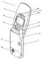
この発明の実施の形態について図面を参照し説明する。図1は本発明の実施の一形態であるクラムシェルタイプのカメラ付携帯電話機1を開いた状態での外観を示す斜視図である。携帯電話機1は第1の筐体2と第2の筐体3からなり、第1の筐体2と第2の筐体3は、ヒンジ4を介して連結され、ヒンジ4を軸として角変位自在に動くことで折り畳み可能に構成されている。図1に示すように携帯電話機1は第1の筐体2には第1表示部5を備える。第1表示部5は携帯電話機1が折り畳まれた時に内側に位置するように配置されている。第1表示部5は液晶ディスプレイやELディスプレイなどで実現され、後述する第1表示ドライバ部43を介して送られてくる画像データに基づく画像を表示する。また、第1表示部5の上部には通話時に使用する第1のスピーカー6を備える。
【0054】
次に本発明の実施の一形態である携帯電話機1の第2の筐体3について説明する。入力ボタン群7は、数字および文字を入力するためのキーなどから構成される。機能ボタン群8は携帯電話機における各種設定/機能切替を行うためのボタン群であり、電源のON/OFF切替を行う電源ボタン9、後述するカメラ機能の第1のシャッターボタン10、メール機能とガイダンス表示を行うメール/ガイダンス用ボタン11、通話開始とスピーカー受話を行う開始/スピーカー受話ボタン12、機能選択画面での上下左右選択と決定を行う4方向ボタンと決定ボタンで構成されたマルチガイドボタン13から構成される。また、第2の筐体102の下部には送話マイク14を備えている。
【0055】
携帯電話機1の第2の筐体3の配置構成としては、ヒンジ4、機能ボタン群8、入力ボタン群7、送話マイク14の順番に配置するのが普通であるが、これに限定されるものではない。
【0056】
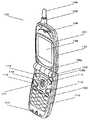
図2は、図1に示された携帯電話機1を背面側からの外観を示す斜視図であり、図3は携帯電話機1を折り畳んだ状態での外観斜視図である。図2または図3に示すように、第1の筐体2の背面は、ヒンジ4側から順番にカメラ部21とライト部22が並んで配置され、第2表示部20、第2のシャッターボタン23および第2の操作ボタン群24が続いて配置される。
【0057】
第2表示部20は携帯電話機1が折り畳まれた時に外側に位置するように配置される。第2表示部20は液晶ディスプレイやELディスプレイなどで実現される。後述する第2表示ドライバ部44を介して送られてくる撮像画像や時刻情報、電波強度、メール受信表示等のキャラクタ画像の画像データに基づく画像を表示する。これらの画像を表示する際に、第2表示ドライバ部44から第2表示部20に送られてくる画像データは、表示した時にヒンジ4方向が上になるように表示される。第2表示部20は、ヒンジ4方向が上になるように画像表示を行うことにより、ユーザーは携帯電話機1を折り畳んだ状態で使用する際に、ヒンジを上に向けて使用することになり、ユーザーが携帯電話機1を開いた状態でも閉じた状態でも第2の筐体3の向きが変わらない。言い換えれば、携帯電話機1を開いたり閉じたりするたびに、携帯電話機1の向きを変えたり持ち替えたりする必要がなくなり、操作性および利便性が向上する。第2表示部20での画像表示には撮像画像も含まれ、撮像画像を見る場合にも、携帯電話機1の向きを変えたり持ち替えたりする必要がなくなり、操作性および利便性が向上する。
【0058】
また、後述するようにアンテナを第1の筐体2の背面から別の場所に移したことにより、第1の筐体2の背面に制約がなくなり、従来よりも大きなサイズの第2表示手段20を設けることができ、テキストや撮像画像の大量の情報表示が可能である。さらに第2の操作ボタン群24を設けることにより、携帯電話機1を閉じた状態であっても、メールの内容確認や住所録の参照、複数画像の順次表示等のさまざまな表示が第2表示部20にて可能になる。第2表示部20での画像表示には撮像画像も含まれ、ユーザーは撮像画像を折り畳んだ状態でも第2表示部20にて大きな画面で確認することができる。従って、撮像画像を見る場合にも、携帯電話機1を開いたり閉じたりする必要がなくなり、操作性および利便性が向上する。
【0059】
カメラ部21は撮像レンズとCCD(Charge Coupled Device)イメージセンサあるいはCMOS(Complementary Metal Oxide Semiconductor)イメージセンサなどの撮像素子とRGBの3色のカラーフィルタとを備える。カメラ部21は被写体で反射されて撮像レンズに入射した光を、カラーフィルタを通してRGBの3色光にし、RGBの3色光をそれぞれ前記撮像素子に変換する。図2に示すようにカメラ部21は携帯電話機1が折り畳まれた時に外側にあって、ヒンジ4と第2表示部との間に位置するように設けられている。ユーザーは携帯電話機1を開いて撮影する時には、第2の筐体3を持って撮影する。カメラ部21は上記配置により、結果的にヒンジ4の近くに設けられるので、第1の筐体2を持つ時、カメラ部21の近辺を支持することから、撮影時にユーザーによる手ブレの影響を減少させることができる。しかも、アンテナを第1の筐体2の背面から除いたことによる大きな第2表示部20によって、被写体撮影時に、被写体からも大きな画面にて手ブレの少ない自画像を容易に確認することができる。
【0060】
ライト部22は、カメラ部21で撮像する際の補助光源として使われる。一般的に、キセノン管を用いるものが多いが、最近ではRGBのLEDを同時発光させて、白色光を発光させて補助光源に用いるものもある。
【0061】
第2のシャッターボタン23は、第1の筐体2の背面中央に配置され、図3に示す携帯電話機1を折り畳んだ状態では第2表示部20の下側に位置する。この位置に第2のシャッターボタン23を配置することにより、ユーザーは折り畳んだ状態で簡単にシャッターボタン位置を確認し、容易に撮影することができる。また、従来機種のように第1の筐体の側面等に小さく設けられた、位置の確認しづらいシャッターボタンを探す必要がなくなり、操作性および利便性が向上する。
【0062】
また、第2のシャッターボタン23の両横には第2表示部3を用いて各種設定/操作を行うための第2の操作ボタン群24a,24bが設けられている。第2の操作ボタン群は、第2表示部20と連動して、各種機能設定,アドレス帳の表示/検索,メールの確認/表示/発信を操作することができる。また、撮影時のズーム操作や複数の撮像画像の順送り/逆送り等を操作することができる。
【0063】
この位置に第2の操作ボタン群24を配置することにより、ユーザーは折り畳んだ状態で簡単に第2の操作ボタン群24位置を確認し、容易に第2の操作ボタン群24を操作することができる。
【0064】
図2に戻り、第2の筐体3の背面にはアンテナ部25と上下可能なヘリカル部26、バッテリーを格納するバッテリー部27と着信音を鳴らす第2のスピーカー28を備えている。
【0065】
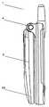
図3は、携帯電話機1を折り畳んだ状態での外観斜視図を示し、図4は、同じく携帯電話機1を折り畳んだ状態での外観側面図である。以下、図3、図4を用いて説明を続ける。
【0066】
第1の筐体2はヒンジ4を通して第2の筐体3と機構的に接続されるが、ヒンジ4内には第1の筐体2と第2の筐体3を電気的に接続するための可撓性基板が組み込まれている。第1の筐体2のヒンジ付近には可撓性基板やケーブルを第1の筐体2内に設けられた各種基板に接続するためのコネクターがあり、このコネクターの厚みが第1の筐体2の厚みに最も影響する。一方、カメラ部21の厚みは前記コネクターの厚みよりも薄いため、前記コネクター近辺にカメラ部21を配置しても、第1の筐体2の厚みには影響しない。したがって、従来の携帯電話機は、カメラ部が第1の筐体2の先端付近(図3での下方付近)に配置されていたために、カメラ部の厚みによって、アンテナ部を除いた第1の筐体2の先端付近の厚みが決まっていたが、カメラ部をアンテナ部25と第2表示部20の間、すなわちヒンジ4付近に配置したことから第1の筐体2の中央部は第2表示部20の厚みを確保し、第1の筐体2の先端付近に至ってはさらなる薄型化/小型化が可能になった。図4に示すように、第1の筐体2は中央部から先端部にかけて曲線状に厚みが狭まっているが、折り畳んだ状態で携帯電話機1の下部に相当する第1の筐体2の先端付近が薄型化される形状にすることにより、ユーザーが洋服のポケット等に携帯電話機1を収納する際に収納しやすく、利便性が向上している。
【0067】
また、カメラ部21と第2のシャッターボタン23または第2の操作ボタン群24の間に第2表示部を配置することによりカメラ部21と第2のシャッターボタン23または第2の操作ボタン群24の間に一定の距離が保てる。ユーザーが第2のシャッターボタン23または第2の操作ボタン群24を操作する際に、ユーザーの指が誤ってカメラ部21に触れたり、カメラ部21の視界を遮ることを防ぐことができる。ユーザーの指がカメラ部21に触れて、レンズ等の部品に傷やゴミが付くことを防ぐことは、結果として携帯電話機の耐久性の向上ならびに性能維持が図られる。
【0068】
さらに、折り畳んだ状態でヒンジ4側を上にして持つように構成することにより、ユーザーが折り畳んだ状態で携帯電話機1を持った時に、ユーザーの手でカメラ部21を塞ぐことがなくなり、カメラ部21の位置を気にせずに携帯電話機1を持つことができる。
【0069】
本発明の実施の一形態である携帯電話機1を用いてカメラ撮影を行う場合の利用方法を、図5を用いて説明する。図5(a)は撮影者が被写体を撮影する場合の一般的な利用方法を示す。携帯電話機1を開き、カメラ部21を被写体に向け、撮影者は第1表示部5をファインダーとして利用する。シャッターボタンは第1のシャッターボタン10を使用するが、第1の筐体2の背面に備えた第2のシャッターボタン23を使用することも可能である。図5(b)は撮影者が撮影者自身を撮影する場合の一般的な利用方法を示す。この場合、撮影者は第2表示部20をファインダーとして利用することにより、撮影画像を確認しながら撮影をすることが可能である。
【0070】
一般的な携帯電話機では、第2表示部20で表示する際には、画面確認時の違和感をなくすため、画像を左右反転させ、鏡のように表示することが多いがそれに限定されるものではない。なお、本発明の実施の一形態である携帯電話機1では、携帯電話機1を開いた状態でも利用者自身を撮影可能だが、わざわざ開くよりも、折り畳んだ状態で撮影した方が使い勝手が良い。
【0071】
次に本発明の実施の一形態である携帯電話機1のアンテナ部25について詳細に説明する。図6は携帯電話機1の第2の筐体3の断面図である。アンテナ部25のホイップ部30が2の筐体3内の左端側に格納可能に構成されており、ヘリカル部26は筐体外に露出している。ホイップ部30とヘリカル部26は、通話時の電波強度に応じて第2の筐体3から引き出し可能である。また、必ずしも上記ホイップ部30とヘリカル部26で構成されるアンテナに限定される必要はなく、例えば図7に示すように、逆F型内蔵アンテナ32を第2の筐体3のヒンジ4近く上部(図7(a))、もしくは第1の筐体2の上部(図7(b))に配置してもよい。
【0072】
次に携帯電話機1の内部回路について、内部ブロック図である図8とともに説明する。制御部40は携帯電話機1を構成する各部位の動作を制御する制御手段、シャッターボタン制御手段、バックライト制御手段、ライト制御手段および表示制御手段である。画像処理部41は、増幅部、A/D(アナログ/デジタル)変換部、信号処理部からなる。増幅部は、カメラ部21から送られてくるRGBに対応した電気信号を増幅し、A/D変換部に送る。A/D変換部は増幅部で変換されたRGBに対応した電気信号(アナログ)をデジタル信号に変換して画像データを出力し、信号処理部に送る。信号処理部は、A/D変換部から送られてくる画像データに対して、画素の補間処理などの信号処理を行う。また信号処理部は、制御部40から送られてくる制御信号に基づいて、信号処理を施した画像データを第1メモリ42に送る。カメラ部21および画像処理部41は、入射光を電気信号に変換して画像データとして出力する撮像手段である。第1メモリ42は、信号処理部から連続的に送られてくる画像データを一時的に記憶している。たとえば、時間的に古い画像データは消去する、あるいは最も新しい画像データを上書きすることで一時的に記憶する。
【0073】
制御部40は、第1および第2表示ドライバ部43,44に制御信号を送信するとともに、第1メモリ42に記憶された画像データを、第1および第2表示ドライバ部43,44に送る。第1および第2ドライバ部43,44は、第1および第2表示部5,20に表示しようとする画像データに従って、第1および第2表示部5,20の各画素電極に対して駆動電圧を印加する。
【0074】
第1および第2バックライト45,46は発光素子である発光ダイオードなどから構成され、第1および第2表示部5,20に光を当てて輝度を増加させる。第1および第2バックライト45,46の点灯、消灯の制御および輝度調整などの制御は、制御部40によって行われる。また、第1および第2バックライト45,46は各々独立して制御することが可能であり、画像が第1表示部5に表示されている時は第1バックライト45が、第2表示部20に表示されている場合は第2バックライト46が点灯するように制御される。なお、第1および第2バックライト45,46はユーザーによって消灯するための所定の操作が行われるまで点灯する構成としてもよいし、点灯してから所定時間が経過すると消灯する構成としてもよい。
【0075】
第1の操作ボタン群47は前述した第2の筐体3の入力ボタン群7と機能ボタン群8から構成される。第2の操作ボタン群は前述したように第1の筐体2に設置されている。
【0076】
第1および第2のシャッターボタン10,23は、第1メモリ42に連続的に送られ、一時的に記憶されている画像データの中からユーザーが保存を希望する画像データを、第2メモリ48に記憶させる時に、ユーザーによって操作され、記憶させる旨の指示信号を制御部40に出力する。制御部40は第1および第2のシャッターボタン10,23からの指示信号に応答して、第1メモリ42に記憶されている画像データを第2メモリ48に記憶させる。なお、第2メモリ48は、第1メモリ42に記憶されている画像データ、およびアンテナ部25を介して受信した各種受信データを記憶する受信手段である。また、第2のシャッターボタン23は図3に示すように、第2表示部20の下部に携帯電話機1が折り畳まれた時に外側に位置するように配置されている。第1のシャッターボタン10は図1に示すように、機能ボタン群8に配置されている。第1のシャッターボタン10は独立して配置されてもよいし、他の機能ボタンと兼用してもよい。
【0077】
開閉検出部49は携帯電話機1が折り畳まれているか否かを検出する検出手段である。ヒンジ4内部に図示しない検出スイッチが設けられており、開閉状態に応じて信号が制御部40に送られ、制御部40によって携帯電話機1が折り畳まれているかどうかを判断する。
【0078】
アンテナ部25は、無線電波を介して基地局と無線通信を行うときに、音声データ、文字データおよび画像データなどを送受信する。無線部50は、受信時は、基地局からアンテナ部25を介して受信したデータを復調し、送信時は、通信制御部51から送られてくる文字データおよび画像データを所定のプロトコルに基づいて制御部40に送る。無線部50、通信制御部51を介して受信した相手先からの受信データは、第2メモリ48に記憶される。図8に示す本発明の実施の一形態である携帯電話機1はテレビジョン信号も受信可能であり、アンテナ部25から、無線通信用電波とテレビジョン放送信号波を分離するための分波器52を備えている。分波器52は無線通信用電波を無線部50に、テレビジョン信号放送波をチューナー53に送る。テレビジョン信号放送波を受信したチューナー53は、信号処理回路に受信したチャンネルの信号を信号処理回路54に送る。信号処理回路54で映像信号、音声信号に分離し、映像信号は第1または第2表示部5,20に、音声信号は第1または第2のスピーカー8,28にて出力される。
【0079】
制御部40は、第1メモリに一時的に保存されている画像データに基づく画像を表示する表示部を、開閉検出部49の検出結果に基づいて切り換える。開閉検出部49によって、携帯電話機1が折り畳まれていることが検出された場合、制御部40は、第1メモリ42からの画像データを第2表示ドライバ部44に出力し、第2表示部20に画像を表示させる。開閉検出部49によって、携帯電話機1が折り畳まれていない(開いている)ことが検出された場合、制御部40は、第1メモリ42からの画像データを第1表示ドライバ部43に出力し、第1表示部5に画像を表示させる。
【0080】
前述のようにカメラ部21は、携帯電話機1が折り畳まれたときの外側に設けられているので、携帯電話機1のユーザー以外の被写体を撮像するときは、図5(a)に示すように、ユーザーは、携帯電話機1を開いた状態でカメラ部21をユーザーと反対側にある被写体側に向けて撮像する。この状態では、携帯電話機1が開いていること、すなわち折り畳まれていないことが開閉検出部49によって検出され、カメラ部21から出力された画像データに基づく画像が第1表示部5に表示される。これによって、ユーザーは第1表示部5を撮像時のファインダーとして使用することができる。
【0081】
一方、ユーザー自身を被写体として撮像するときは、図5(b)に示すように、ユーザーは、携帯電話機1を折り畳んだ状態でカメラ部21をユーザー側に向けて撮像する。この状態では、携帯電話機1が折り畳まれていることが開閉検出部49によって検出され、カメラ部21から出力された画像データに基づく画像が第2表示部20に表示される。これによって、ユーザーは第2表示部20を撮影時のファインダーとして使用することができる。
【0082】
本発明の実施の一形態である携帯電話機1は、ユーザーが携帯電話機1の第2の筐体3を固定したまま、第1の筐体2を折り畳むもしくは開くだけで、撮像時にファインダーとして使用する表示部5,20が適切に切り換わり、撮影可能となるので、ユーザーは被写体を切り替えるために、従来の携帯電話のように第2の筐体3を持ち替える必要がなくなり、被写体を切り替える際のユーザーの手間を省くことができ、操作性および利便性が向上する。
【0083】
次に、第1および第2シャッターボタン10,23の制御について説明する。
【0084】
制御部40は、開閉検出部49の検出結果に基づいて、入力が有効なシャッターボタンを切り換える。開閉検出部49によって、携帯電話機1が折り畳まれていることが検出された場合、制御部40は、第2シャッターボタン23の入力を有効とする。開閉検出部49によって、携帯電話機1が開いていることが検出された場合、制御部40は、第1シャッターボタン10の入力を有効とし、第2シャッターボタン23の入力を無効とする。第1および第2シャッターボタン10,23の入力を無効とするには、たとえば、第1および第2シャッターボタン10,23をユーザーが操作できないように固定する、第1および第2シャッターボタン10,23を固定せずに、第1および第2シャッターボタン10,23から制御部40への指示信号を出力しないようにする、制御部40が第1および第2シャッタボタン10,23からの指示信号を処理しないようにするなどの方法で実現できる。
【0085】
前述のようにカメラ部21は、携帯電話機1が折り畳まれたときの外側に設けられているので、携帯電話機1のユーザー以外の被写体を撮像するときは、ユーザーは、携帯電話機1を開いた状態でカメラ部21をユーザーと反対側にある被写体側に向けて撮像する。この状態では、携帯電話機1が開いていることが開閉検出部49によって検出され、第1シャッターボタン10からの指示が有効となる。ユーザーは、ファインダーである第1表示部5を見ながら、第1表示部5と同じ側に配置されている第1シャッタボタン10を操作する。
【0086】
一方、ユーザー自身を被写体として撮像するときは、本発明の実施の一形態では、ユーザーが携帯電話機1を折り畳んだ状態でカメラ部21をユーザー側に向けて撮像することが可能である。この状態では、携帯電話機1が折り畳まれていることが開閉検出部49によって検出され、第2シャッタボタン23からの指示が有効となる。ユーザーは、ファインダーである第2表示部20を見ながら、第2表示部20と同じ側に配置されている第2シャッターボタン23を操作する。
【0087】
このように、携帯電話機1を折り畳むもしくは開くだけでファインダーとして使用する第1または第2表示部5,20と同じ側に位置する第1または第2シャッターボタン10,23からの指示が有効となるので、ユーザーは第1または第2シャッターボタン10,23を見て確認しながら入力することができ、操作性が向上する。
【0088】
また一般的に、ファインダーとして使用する表示部と反対側に位置するシャッターボタンは、ユーザーから見え難いために、ユーザーが携帯電話機1を把持するときやシャッターボタンの入力以外の操作を行うときに誤って入力してしまう場合がある。本発明の実施の一形態では、携帯電話機1を開くだけでファインダーとして使用する第1表示部5と反対側に位置する第2シャッターボタン23からの指示が無効になるので、ユーザーによる誤操作を防止することができる。
【0089】
なお、携帯電話機1が開いていることが検出されたときに、第2シャッターボタン23の入力を無効とせず有効としてもよい。この場合、ユーザーは第1および第2シャッターボタン10,23のどちらも操作することができる。また、第1シャッターボタン10は、折り畳まれたときの内側に配置されているので、携帯電話機1が折り畳まれているときにはユーザーが操作できない。したがって、開閉検出部49によって、携帯電話機1が折り畳まれていることが検出されたときの第1シャッターボタン10の入力は、無効または有効のいずれとしてもよい。
【0090】
第1および第2バックライト45,46の制御について説明する。
【0091】
制御部40は、開閉検出部49の検出結果に基づいて、第1および第2バックライト45,46の点灯、消灯を切り換える。開閉検出部49によって、携帯電話機1が折り畳まれていることが検出された場合、制御部40は、第2バックライト46を点灯し、第2表示部20の輝度を増加させる。開閉検出部49によって、携帯電話機1が開いていることが検出された場合、制御部40は、第1バックライト45を点灯し、第1表示部5の輝度を増加させる。
【0092】
前述のように、ユーザーが被写体をユーザー自身以外として撮像するときは、第1表示部5がファインダーとして使用され、カメラ部21から取り込まれた画像データが第1表示部5に表示される。このとき、第1バックライト45が点灯し、第1表示部5の輝度を増加させる。
【0093】
一方、ユーザーが被写体をユーザー自身として撮像するときは、第2表示部20がファインダーとして使用され、カメラ部21から取り込まれた画像データが第2表示部20に表示される。このとき、第2バックライト46が点灯し、第2表示部20の輝度を増加させる。
【0094】
このように、携帯電話機1を折り畳む、もしくは開くと、ファインダーとして使用する表示部に光を供給するバックライトが点灯するので、表示された画像が見やすくなり、視認性が向上する。
【0095】
図9は、携帯電話機1の撮像処理を示すフローチャートである。特に、携帯電話機1を折り畳んで撮影した際に、撮像画像を180度回転させることについて説明する。なお、携帯電話機1は、折り畳まれた状態からでも、開いた状態からでも所定の操作によって撮像可能な状態、いわゆる撮像モードに設定することができる。
【0096】
まず、ステップS1では、制御部40が、開閉検出部49の検出結果に基づいて携帯電話機1が折り畳まれているか否かを判断する。折り畳まれずに開いていればステップS2に進み、折り畳まれていればステップS8に進む。ステップS2では、第1バックライト45を点灯する。ステップS3では、撮像部2から取り込んだ画像データを第1表示部5に表示し、ステップS4に進む。
【0097】
ステップS4では、制御部40が、開閉検出部49の検出結果に基づいて携帯電話機1が折り畳まれているか否かを判断する。開いていればステップS5に進み、折り畳まれていれば第1バックライト45の点灯及び第1表示部5への画像表示を中止し、ステップS8に進む。
【0098】
ステップS5では、制御部40が、第2シャッターボタン23の入力を無効にし、第1シャッターボタン10が押されたか否かを検出する。押されていればステップS6に進み、押されていなければステップS7に進む。ステップS6では、第1メモリ42に一時的に記憶されている画像データを第2メモリ48に記憶してステップS7に進む。ステップS7では、制御部40が、撮像モードを終了する所定の操作がユーザーによって行われたか否かを判断する。操作が行われていれば処理を終了し、行われていなければステップS4に戻る。撮像モードが終了すると、第1および第2表示部5,20には所定の待受画面などが表示される。
【0099】
ステップS1で、制御部40によって携帯電話機1が折り畳まれていると判断されていればステップS8に進んで、第2バックライト46を点灯する。ステップS9では、カメラ部21から取り込んだ画像データを第2表示部20に表示し、ステップS10に進む。
【0100】
ステップS10では、制御部40が、開閉検出部49の検出結果に基づいて携帯電話機1が折り畳まれているか否かを判断する。開いていれば第2バックライト46の点灯及び第2表示部20への画像表示を中止し、ステップS2に進み、折り畳まれていればステップS11に進む。
【0101】
ステップS11では、制御部40が、第2シャッターボタン23が押されたか否かを検出する。押されていればステップS12に進み、押されていなければステップS13に進む。ステップS12では、第1メモリ42に一時的に記憶されている画像データを180度回転したものを第2メモリ48に記憶してステップS13に進む。
【0102】
これは携帯電話機1を開いた状態と折り畳んだ状態とでは、カメラ部21の上下方向が逆になるためであり、折り畳まれた状態では撮影時に画像データを180度回転させてから第2メモリ48に記憶することにより、後にその画像データを第1または第2表示部5,20のいずれに表示させた場合でも、画像の上下が逆になることがなくなる。ステップS13では、制御部40が、撮像モードを終了する所定の操作がユーザーによって行われたか否かを判断する。操作が行われていれば処理を終了し、行われていなければステップS10に戻る。撮像モードが終了すると、第1および第2表示部5,20には所定の待受画面などが表示される。
【0103】
以上のように、携帯電話機1の開閉を検出することによって、撮像時のファインダーとして使用する表示部が適切に切り換わるので、ユーザーは切り換えのためのボタン操作を行う必要がなく、切り換えのための手間が省かれ、操作性および利便性が向上する。また、携帯電話機1の開閉が検出されることによって、ファインダーとなる表示部と同じ側のシャッターボタンの入力が有効となるので、ファインダーを見ながらシャッターボタンを確実に入力することが可能となり、操作性が向上する。また、ファインダーとなる表示部と反対側のシャッターボタンの入力は無効となるので、誤ってシャッターボタンを押してしまうなどの誤操作を防止することができる。また、携帯電話機1の開閉が検出されることによって、ファインダーとなる表示部のバックライトが点灯するので、画像が見やすくなり、視認性が向上する。さらに、折り畳んだ状態で撮影した場合には、画像データの保存時に画像データを180度回転させてから第2メモリ48に保存するので、後から保存した画像データを表示させた場合に、画像の上下が逆に表示されることを防止することができる。
【0104】
なお、図1〜5において、第1および第2表示部5,20は、第1の筐体2に配置されている場合を示したが、これに限らず、第1および第2表示部5,20はそれぞれ、携帯電話機1が折り畳まれたときの内側および外側に位置するように配置すればよい。
【0105】
なお、本発明の実施の一形態として上述した携帯電話機1は、折り畳んだ状態で撮影した場合に、撮像画像を180度回転して保存することを記載したが、これに限定されるものではなく、開いた状態で撮像した画像を180度回転して保存する構成としてもよい。この場合、図9のステップS6にて画像データの180度回転が行われ、メモリ48に記憶される。
【0106】
また、本発明の実施の一形態として携帯電話機1について説明したが、これに限らず、ノート型PC(パーソナルコンピュータ)、PDA(Personal Digital Assistance)などであって、折り畳み可能に構成され、撮像部と折り畳まれたときの内側および外側にそれぞれ表示部を備える構成であれば、本発明は適用可能である。
【0107】
さらに、表示部5,20をファインダーとして使用する場合に限らず、所定の表示を表示部5,20に表示させる場合に、表示させる表示部の切り換えを携帯電話機1の開閉を検出して行うようにしてもよい。
【0108】
今回開示された実施の形態はすべての点で例示であって制限的なものではないと考えられるべきである。本発明の範囲は上記した説明ではなくて特許請求の範囲によって示され、特許請求の範囲と均等の意味および範囲内でのすべての変更が含まれることが意図される。
【0109】
【発明の効果】
以上のように本発明によれば、第1の筐体と第2の筐体が折り畳まれていないことが検出されたことによって、または、これらが折り畳まれていることが検出されたことによって、ファインダー画像やキャラクタ画像の表示方向が制御されるため、ユーザーが携帯電話機を開いた状態でも閉じた状態でも第2の筐体の向きを変えることなく、ファインダー画像やキャラクタ画像を見ることができる。
【0110】
従って、携帯電話機を開いたり閉じたりするたびに、携帯電話機の向きを変えたり持ち替えたりする必要がなくなり、操作性および利便性が向上する。
【0111】
また本発明によれば、第1の筐体と第2の筐体が折り畳まれている状態において第2表示手段が撮影時のファインダーとして使用されている状態から、第1の筐体と第2の筐体が開かれると、第2表示手段へのファインダー画像の表示が中止されて第1表示手段にファインダー画像が表示されるように切り換えられる。したがって、携帯電話機を第1の筐体と第2の筐体が折り畳まれている状態から開いた状態にしたときに、ユーザーは、ファインダーとして使用する表示手段の切り換えのための操作をする必要がなくなるため、操作性および利便性が向上する。
【0121】
また本発明によれば、携帯電話機を閉じた状態でユーザー自身を撮影する場合に、第1の筐体の外面に設けられたシャッターボタンを押すことで撮影が可能になる。これによって、ユーザーは閉じた状態で簡単にシャッターボタン位置を確認し容易に撮影することができる。従って、従来機種のように、第1の筐体の側面等に小さく設けられたボタン位置の確認しずらいシャッターボタンを探す必要がなくなり、操作性および利便性が向上する。
【0122】
また本発明によれば、撮像手段とシャッターボタンの間に第2表示手段が配置されることから、撮像手段とシャッターボタンの間に一定の距離が確保できる。これによって、ユーザーが撮影しようとする際にシャッターボタンを押すユーザーの手が撮像手段に被さることを防ぐことができる。従って、ユーザーが撮像手段の位置を気にせずにシャッターボタンを押すことができることから、操作性および利便性が向上すると同時に、ユーザーの指が撮像手段に触れて、レンズ等の部品に傷やゴミが付くことを防ぐことができ、結果として携帯電話機の耐久性の向上ならびに性能維持が図られる。
【0123】
また本発明によれば、第2表示手段を用いて、機能設定やアドレス帳やメールの確認/表示等の各種情報を選択的に表示または発信することが可能になる。また、操作手段にて折り畳んだ状態であっても、撮像画像のズーム操作等が可能になる。これによって、携帯電話機を閉じた状態であっても、多くの操作を行うことができ、携帯電話機を開かなくても済むようになり、操作性および利便性が向上する。
【0124】
また、本発明によれば、撮像手段と操作手段の間に第2表示手段が配置されることから、撮像手段と操作手段との間に一定の距離が確保できる。これによって、ユーザーが撮影しようとする際に操作手段を操作するユーザーの手が撮像手段に被さることを防ぐことができる。従って、ズーム操作等の撮影に関する各種設定時にユーザーが撮像手段の位置を気にせずに操作手段の操作ができることから、操作性および利便性が向上すると同時に、ユーザーの指が撮像手段に触れて、レンズ等の部品に傷やゴミが付くことを防ぐことができ、結果として携帯電話機の耐久性の向上ならびに性能維持が図られる。
【0125】
また本発明によれば、第2表示手段と操作手段を用いて、機能設定の操作やアドレス帳の表示や検索またはメールの確認や表示や発信が可能となる。これによって、携帯電話機を閉じた状態であっても、多くの操作を行なうことができ、携帯電話機を開かなくても済むようになり、操作性および利便性が向上する。
また本発明によれば、携帯電話機を開いた状態で撮影した時と、折り畳んだ状態で撮影した時では、記憶される画像の向きが180度異なる。
【0126】
これによって、記憶された画像を表示する際には、第1表示手段と第2表示手段にかかわらず、また、開いた場合と折り畳んだ場合にかかわらず、表示される画像は上下方向が同じになる。従って、折り畳んだ状態で撮影した画像が、後に再生した場合に本来、上にくるべき画像の方向が下向きに表示されるということがなくなり、利便性が向上する。
【図面の簡単な説明】
【図1】 本実施の形態に係る携帯電話機の外観斜視図である。
【図2】 本実施の形態に係る携帯電話機の背面側からの外観斜視図である。
【図3】 本実施の形態に係る携帯電話機の折り畳んだ状態での外観斜視図である。
【図4】 本実施の形態に係る携帯電話機の折り畳んだ状態での外観側面図である。
【図5】 本実施の形態に係る携帯電話機の利用方法を示す説明図である。
【図6】 本実施の形態に係る携帯電話機の断面図である。
【図7】 本実施の形態に係る携帯電話機の他の例を示す断面図である。
【図8】 本実施の形態に係る携帯電話機の構成を示すブロック図である。
【図9】 本実施の形態に係る携帯電話機の撮像処理を示すフローチャートである。
【図10】 従来の携帯電話機の外観斜視図である。
【図11】 従来の携帯電話機の背面側からの外観斜視図である。
【図12】 従来の携帯電話機の折り畳んだ状態での外観斜視図である。
【図13】 従来の携帯電話機の折り畳んだ状態での外観側面図である。
【図14】 従来の携帯電話機の利用方法を示す説明図である。
【符号の説明】
1 携帯電話機
2 第1の筐体
3 第2の筐体
4 ヒンジ
5 第1表示部
10 第1のシャッターボタン
20 第2表示部
21 カメラ部
23 第2のシャッターボタン
24 第2の操作ボタン群
25 アンテナ部
26 ヘリカル部
40 制御部
42 第1メモリ
48 第2メモリ
49 開閉検出部[0001]
BACKGROUND OF THE INVENTION
The present invention relates to a mobile phone having a photographing function.
[0002]
[Prior art]
In recent years, mobile phones have become widespread, but their shapes are roughly classified into three types: straight type, flip type, and clamshell type. Above all, the clamshell type can be miniaturized by folding, so the needs are higher than the other two types.
[0003]
Recently, a mobile phone having a liquid crystal sub-display on the back of the liquid crystal display or a camera function has been proposed.
[0004]
FIG. 10 is a perspective view showing an external appearance of a conventional clamshell type camera-equipped
[0005]
The open / close detection unit 109 is a detection unit that detects whether or not the
[0006]
Next, the
[0007]
As an arrangement configuration of the
[0008]
FIG. 11 is a perspective view showing the appearance of the
[0009]
The
[0010]
The
[0011]
The
[0012]
The back surface of the second housing includes a
[0013]
FIG. 12 shows an external perspective view of the
[0014]
A method of using the camera using the conventional
[0015]
[Problems to be solved by the invention]
Many problems remain in the clamshell type camera-equipped mobile phone including the two display means as described above.
[0016]
The first problem is the problem of changeover. In the case of a clamshell type cellular phone, the cellular phone is used with the
[0017]
Similarly, when the
[0018]
Conversely, even when the
[0019]
The second problem is that the
[0020]
The third problem also relates to the antenna. Since the
[0021]
The fourth problem is a problem related to miniaturization of the mobile phone. The user needs to reduce the size of the mobile phone. In the case of the camera-equipped
[0022]
The fifth problem relates to camera shake. When the camera unit is arranged at the tip of the
[0023]
[Means for Solving the Problems]
In the first invention, the first casing and the second casing are configured to be foldable by the connecting portion.First display means is disposed on the inner surface of the first casing, and second display means and imaging means capable of photographing in an open state and a folded state are provided on the outer surface of the first casing. ArrangedA mobile phone,Opening / closing detection means for detecting whether or not the first casing and the second casing are folded, and when the character image is displayed on the first display means, the connecting portion is at the bottom. In the mobile phone comprising the display control means to be displayed on the display, the display control means folds the first casing and the second casing when the first display means is used as a finder during photographing. By detecting that the opening / closing detection means is not, the finder image based on the image data captured by the imaging means is displayed on the first display means so that the connecting portion is down, The display control means is further configured to use the second display means as a viewfinder at the time of shooting when the first casing and the second casing are folded, and the character image. When the display means is used, the open / close detection means detects that the first casing and the second casing are folded, so that the imaging means can detect the first casing and the second casing. The display direction of the viewfinder image and the display direction of the character image based on the image data captured in a state that is upside down with respect to the direction when the second case is not folded are set to the first case. And the second display means that is upside down with respect to the direction in which the second casing is not folded is controlled so that both are displayed with the connecting portion in the upward direction. Further, the display control means rotates the image data picked up by the image pickup means in a state where the mobile phone is folded, and then stores the image data after rotating by 180 degrees. Therefore, when reproducing and displaying the image data captured and stored, when the first display means reproduces, it is determined that the first casing and the second casing are not folded. The detection means detects the folded state of the first casing and the second casing at the time of photographing so that the display direction of the stored image data is displayed downward. In the case where the control is performed independently of each other and the second display means reproduces, the opening / closing detection means detects that the first casing and the second casing are folded, so that the storage is performed. The displayed direction of the image data is controlled regardless of the folded state of the first casing and the second casing at the time of photographing so that the connecting portion is displayed upward.It is a mobile phone characterized by doing.
[0024]
According to the present invention,When the first display means is used as a viewfinder at the time of photographing, an image taken by the imaging means is detected when the opening / closing detection means detects that the first casing and the second casing are not folded. A finder image based on the data is displayed on the first display means so that the connecting portion is on the bottom. Further, when the second display means is used as a viewfinder at the time of shooting in a state where the first casing and the second casing are folded, and when the second display means is used for displaying a character image. When the open / close detection means detects that the first casing and the second casing are folded, the orientation of the imaging means in the state in which the first casing and the second casing are not folded And the display direction of the finder image and the display direction of the character image based on the image data captured in the upside down direction are the directions when the first housing and the second housing are not folded. Any of the second display means in the upside down state is displayed with the connecting portion as the upward direction. In addition, the image data captured by the imaging unit with the cellular phone folded is stored after being rotated 180 degrees. In addition, when the image data captured and stored by the imaging unit is reproduced and displayed, the first casing and the second casing are not folded when being reproduced on the first display unit. Is detected by the open / close detection means, so that the stored image data is displayed in the downward direction of the connecting portion, regardless of the folded state of the first casing and the second casing at the time of shooting. In addition, when being reproduced on the second display means, the open / close detection means detects that the first casing and the second casing are folded, so that the stored image data The display direction is controlled regardless of the folded state of the first casing and the second casing at the time of photographing so that the connecting portion is displayed upward.
[0025]
in this way,The display direction of the viewfinder image and the character image is controlled by detecting that the first housing and the second housing are not folded or by detecting that they are folded. BecauseOrientation of the second housing regardless of whether the user opens or closes the mobile phoneThe viewfinder image and the character image can be viewed without changing.Therefore, it is not necessary to change the direction of the mobile phone or to change it every time the mobile phone is opened or closed, and the operability and convenience are improved.Further, since the orientation of the stored image differs by 180 degrees between when the cellular phone is opened and when it is folded, when the stored image is displayed, the first display means and the
[0026]
Also, the second invention isThe first casing and the second casing are configured to be foldable by a connecting portion, and a first display means is disposed on the inner surface of the first casing, and the outer surface of the first casing is disposed on the outer surface of the first casing. Whether the first casing and the second casing are folded or not, wherein the second display means and the imaging means capable of photographing in an open state and a folded state are arranged. In a mobile phone comprising: an open / close detection means for detecting the image; and a display control means for displaying the character image on the first display means so that the connecting portion is located below, the display control means comprises: When the second display means is used as a viewfinder at the time of shooting in a state where the first casing and the second casing are folded, the first casing and the second casing are folded. It is detected by the opening / closing detection means Accordingly, the display direction of the finder image based on the image data captured by the imaging unit in a state where the first housing and the second housing are not folded upside down. Is displayed on the second display means that is upside down with respect to the orientation when the first housing and the second housing are not folded. When the mobile phone is opened, the first casing and the second casing are opened, and the first display means is used as a viewfinder at the time of shooting. When the open / close detection means detects that the case and the second case are not folded, the viewfinder image based on the image data taken by the image pickup means to the second display means is displayed. table Is switched to display the finder image on the first display means, and the finder image is displayed on the first display means so that the connecting portion is at the bottom, and the display control means The image data picked up by the image pickup means is stored after being rotated 180 degrees with the telephone folded, and the display control means reproduces and displays the image data picked up and stored by the image pickup means. In this case, when the first display means reproduces, the opening / closing detection means detects that the first casing and the second casing are not folded, so that the stored data is stored. The display direction of the image data is controlled regardless of the folded state of the first casing and the second casing at the time of photographing so that the connecting portion is displayed downward. When the second display means reproduces the image, the open / close detection means detects that the first casing and the second casing are folded, so that the stored image is stored. The display direction of the data is controlled regardless of the folded state of the first casing and the second casing at the time of photographing so that the connecting portion is displayed in the upward direction, and the display control means includes: When the second display means is used for displaying the character image in a state where the first casing and the second casing are folded, the first casing and the second casing are By detecting that the opening / closing detection means is folded, the character image is controlled to be displayed on the second display means with the connecting portion being in the upward direction.It is a mobile phone characterized by this.
[0027]
According to the present invention,When the second display means is used as a viewfinder at the time of photographing in a state where the first housing and the second housing are folded, the first housing and the second housing are folded. Is detected by the open / close detection means, and the image pickup means is based on image data that is taken in an upside down direction with respect to a state in which the first housing and the second housing are not folded. The display portion of the viewfinder image is displayed as the upward direction on the second display means in which the orientation of the viewfinder image is reversed upside down from the orientation when the first housing and the second housing are not folded. It is controlled so that Further, when the cellular phone is folded, the first casing and the second casing are opened, and when the first display means is used as a finder at the time of photographing, the first casing and the second casing are used. When the open / close detection means detects that the body is not folded, the display of the finder image based on the image data captured by the imaging means on the second display means is stopped, and the finder is displayed on the first display means. The display is switched so that the image is displayed, and the viewfinder image is displayed on the first display means so that the connecting portion is at the bottom. Further, the image data captured by the imaging means in a state where the mobile phone is folded is stored after being rotated 180 degrees. Further, when the image data picked up and stored by the image pickup means is reproduced and displayed, it is opened and closed that the first case and the second case are not folded when being reproduced on the first display means. By being detected by the detection means, the display direction of the stored image data is controlled regardless of the folded state of the first casing and the second casing at the time of photographing so that the connecting portion is displayed downward. In the case of reproduction on the second display means, the display direction of the stored image data is detected by the opening / closing detection means detecting that the first casing and the second casing are folded. Is controlled regardless of the folded state of the first casing and the second casing at the time of photographing so that the connecting portion is displayed upward. Further, when the second display means is used for displaying a character image in a state where the first casing and the second casing are folded, the first casing and the second casing are folded. When the open / close detection means detects that the character image is displayed, the character image is controlled to be displayed on the second display means with the connecting portion facing upward.
As described above, when it is detected that the first casing and the second casing are not folded, or when they are detected to be folded, the viewfinder image and the character image are displayed. Since the display direction is controlled, the viewfinder image and the character image can be viewed without changing the orientation of the second housing regardless of whether the user opens or closes the mobile phone.Therefore, it is not necessary to change the direction of the mobile phone or to change it every time the mobile phone is opened or closed, and the operability and convenience are improved.Further, the first casing and the second casing are opened from the state in which the second display means is used as a finder at the time of photographing in a state where the first casing and the second casing are folded. Then, the display of the finder image on the second display means is stopped, and the display is switched so that the finder image is displayed on the first display means. Therefore, when the cellular phone is opened from the state in which the first casing and the second casing are folded, the user needs to perform an operation for switching display means used as a finder. As a result, operability and convenience are improved.
[0028]
In addition, the third invention,In the first invention or the second invention, the character image is a character.It is a mobile phone.
[0030]
Also, the fourth invention isFrom the first inventionThird inventionEitherInThe display control means displays the content of the mail on the second display means in the folded state.It is a mobile phone characterized by this.
[0032]
The fifth invention isFrom the first inventionThird inventionEitherInThe display control means displays the address book on the second display means in the folded state.It is a mobile phone characterized by this.
[0034]
In addition, the sixth inventionIn any one of the first to third inventions, the display control means causes the second display means to display a function setting in the folded state.It is a mobile phone characterized by this.
[0042]
The second7The invention of,FirstNo. 6 from the inventionInventionEitherInSaidOn the outer surface of the first housingArranged,From the imaging meansCaptured imageInstruct memorize,Shutter buttonIncluding furtherThis is a mobile phone.
[0043]
According to the present invention, when the user himself / herself is photographed with the cellular phone closed, photographing can be performed by pressing a shutter button provided on the outer surface of the first housing. As a result, the user can easily check the shutter button position in the closed state and take a picture easily. Therefore, unlike the conventional model, there is no need to search for a shutter button that is small on the side surface of the first housing and the like, and it is difficult to confirm the button position, and operability and convenience are improved.
[0044]
The second8The invention of,First7In the invention ofSaidOn the outer surface of the first housingIsFrom the connecting part side,Arrangement in order of the imaging means, the second display means, and the shutter buttonHas beenIt is a mobile phone characterized by this.
[0045]
According to the present invention, since the second display means is disposed between the imaging means and the shutter button, a certain distance can be ensured between the imaging means and the shutter button. Accordingly, it is possible to prevent the user's hand pressing the shutter button when the user tries to shoot from being put on the imaging unit. Therefore, since the user can press the shutter button without worrying about the position of the image pickup means, the operability and convenience are improved, and at the same time, the user's finger touches the image pickup means and scratches or dust on the lens or other parts. As a result, the durability and performance of the mobile phone can be improved.
[0046]
The second9The invention of,First8th from the inventionInventionEitherInSaidOn the outer surface of the first housingArranged,Operating means for operating the display of the second display means;Including furtherThis is a mobile phone characterized by this.
[0047]
According to the present invention, it is possible to selectively display or transmit various types of information such as function setting, address book and mail confirmation / display using the second display means. Further, even in a state of being folded by the operation means, a zoom operation of the captured image can be performed. As a result, many operations can be performed even when the cellular phone is closed, and the cellular phone need not be opened, improving operability and convenience.
[0048]
The second10The invention of,First9In the invention ofSaidOn the outer surface of the first housingIsFrom the connecting part side,Arrangement in order of the imaging means, the second display means, and the operation meansHas beenIt is a mobile phone characterized by this.
[0049]
Since the second display means is disposed between the imaging means and the operation buttons, a certain distance can be ensured between the imaging means and the operation buttons. Accordingly, it is possible to prevent the user's hand pressing the operation button when the user tries to shoot from being put on the imaging unit. Accordingly, since the user can operate the operation buttons without worrying about the position of the image pickup means at the time of various settings related to shooting such as zoom operation, the operability and convenience are improved, and at the same time, the user's finger touches the image pickup means, Scratches and dust can be prevented from being attached to the lens and other parts, and as a result, the durability and performance of the mobile phone can be improved.
[0050]
The second11The invention of,First4In the invention ofConfirmation, display, or transmission of mail displayed on the second display means in a state in which the first casing and the second casing are folded, arranged on the outer surface of the first casing. Further includes operating means for operatingIt is a mobile phone characterized by this.
[0051]
In a twelfth aspect based on the fifth aspect, the second display means is disposed outside the first casing and the first casing and the second casing are folded. The mobile phone further includes an operation means for operating display or search of the address book displayed on the mobile phone.
[0052]
In a thirteenth aspect based on the sixth aspect, the second display means is disposed outside the first casing and the first casing and the second casing are folded. The mobile phone further comprises operation means for operating the function setting displayed on the screen.
[0053]
DETAILED DESCRIPTION OF THE INVENTION
Embodiments of the present invention will be described with reference to the drawings. FIG. 1 is a perspective view showing an external appearance of a clamshell type camera-equipped mobile phone 1 according to an embodiment of the present invention. The mobile phone 1 includes a
[0054]
Next, the 2nd housing | casing 3 of the mobile telephone 1 which is one Embodiment of this invention is demonstrated. The
[0055]
The arrangement of the
[0056]
2 is a perspective view showing an appearance of the mobile phone 1 shown in FIG. 1 from the back side, and FIG. 3 is an external perspective view of the mobile phone 1 in a folded state. As shown in FIG. 2 or FIG. 3, the
[0057]
The
[0058]
Further, as will be described later, by moving the antenna from the back surface of the
[0059]
The
[0060]
The light unit 22 is used as an auxiliary light source when the
[0061]
The
[0062]
In addition, second
[0063]
By disposing the second
[0064]
Returning to FIG. 2, the
[0065]
FIG. 3 is an external perspective view of the cellular phone 1 in a folded state, and FIG. 4 is an external side view of the cellular phone 1 in a folded state. Hereinafter, the description will be continued with reference to FIGS. 3 and 4.
[0066]
The
[0067]
In addition, by disposing the second display unit between the
[0068]
Further, by being configured to have the hinge 4 side up in the folded state, when the user holds the mobile phone 1 in the folded state, the
[0069]
A use method in the case of performing camera shooting using the mobile phone 1 according to an embodiment of the present invention will be described with reference to FIG. FIG. 5A shows a general usage method when a photographer photographs a subject. The cellular phone 1 is opened, the
[0070]
In general mobile phones, when displaying on the
[0071]
Next, the
[0072]
Next, an internal circuit of the mobile phone 1 will be described with reference to FIG. 8 which is an internal block diagram. The
[0073]
The
[0074]
The first and
[0075]
The first
[0076]
The first and
[0077]
The open /
[0078]
The
[0079]
The
[0080]
As described above, since the
[0081]
On the other hand, when the user himself / herself is imaged as a subject, as shown in FIG. 5B, the user images the
[0082]
A mobile phone 1 according to an embodiment of the present invention is used as a finder at the time of imaging simply by folding or opening the
[0083]
Next, control of the first and
[0084]
Based on the detection result of the open /
[0085]
As described above, since the
[0086]
On the other hand, when the user himself / herself is imaged as a subject, in the embodiment of the present invention, it is possible to image the
[0087]
In this way, the instruction from the first or
[0088]
In general, since the shutter button located on the opposite side of the display unit used as a viewfinder is difficult to see from the user, it is erroneous when the user grips the mobile phone 1 or performs an operation other than the shutter button input. May be entered. In the embodiment of the present invention, since the instruction from the
[0089]
Note that when it is detected that the mobile phone 1 is open, the input of the
[0090]
Control of the first and
[0091]
The
[0092]
As described above, when the user images the subject other than the user himself / herself, the
[0093]
On the other hand, when the user images the subject as the user himself / herself, the
[0094]
Thus, when the cellular phone 1 is folded or opened, the backlight for supplying light to the display unit used as a viewfinder is turned on, so that the displayed image is easy to see and visibility is improved.
[0095]
FIG. 9 is a flowchart showing the imaging process of the mobile phone 1. In particular, a description will be given of rotating a captured image by 180 degrees when the cellular phone 1 is folded and photographed. Note that the mobile phone 1 can be set to a so-called imaging mode in which imaging can be performed by a predetermined operation from the folded state or the opened state.
[0096]
First, in step S <b> 1, the
[0097]
In step S <b> 4, the
[0098]
In step S5, the
[0099]
If it is determined in step S1 that the mobile phone 1 is folded by the
[0100]
In step S <b> 10, the
[0101]
In step S11, the
[0102]
This is because the up-down direction of the
[0103]
As described above, since the display unit used as the finder at the time of imaging is appropriately switched by detecting the opening / closing of the mobile phone 1, the user does not need to perform a button operation for switching. This saves time and improves operability and convenience. In addition, when the opening / closing of the cellular phone 1 is detected, the shutter button on the same side as the display unit serving as the finder becomes valid, so that it is possible to input the shutter button reliably while looking at the finder. Improves. In addition, since the input of the shutter button on the opposite side of the display unit serving as a finder becomes invalid, it is possible to prevent an erroneous operation such as pressing the shutter button by mistake. Further, when the opening / closing of the mobile phone 1 is detected, the backlight of the display unit serving as a finder is turned on, so that the image is easy to see and the visibility is improved. Further, when the image is taken in a folded state, the image data is rotated 180 degrees and stored in the
[0104]
1 to 5 show the case where the first and
[0105]
In addition, although the mobile phone 1 described above as an embodiment of the present invention described that the captured image is rotated 180 degrees and stored when captured in a folded state, the present invention is not limited to this. Alternatively, the image captured in the open state may be rotated 180 degrees and stored. In this case, the image data is rotated 180 degrees in step S6 of FIG.
[0106]
The mobile phone 1 has been described as an embodiment of the present invention. However, the present invention is not limited thereto, and is a notebook PC (personal computer), a PDA (Personal Digital Assistance), etc., and is configured to be foldable. The present invention can be applied to any configuration provided with a display unit inside and outside when folded.
[0107]
Further, not only when the
[0108]
The embodiment disclosed this time should be considered as illustrative in all points and not restrictive. The scope of the present invention is defined by the terms of the claims, rather than the description above, and is intended to include any modifications within the scope and meaning equivalent to the terms of the claims.
[0109]
【The invention's effect】
As described above, according to the present invention,The display direction of the viewfinder image and the character image is controlled by detecting that the first housing and the second housing are not folded or by detecting that they are folded. Therefore, the user can view the viewfinder image and the character image without changing the orientation of the second casing regardless of whether the user opens or closes the mobile phone.be able to.
[0110]
ObedienceThus, each time the mobile phone is opened or closed, it is not necessary to change the direction of the mobile phone or to change it, thereby improving operability and convenience.
[0111]
Also according to the invention,When the first casing and the second casing are opened from the state where the second display means is used as a finder at the time of photographing in a state where the first casing and the second casing are folded. The display of the finder image on the second display means is stopped, and the display is switched so that the finder image is displayed on the first display means. Therefore, when the cellular phone is opened from the state in which the first casing and the second casing are folded, the user needs to perform an operation for switching display means used as a finder. Because it disappears,Operability and convenience are improved.
[0121]
According to the present invention, when the user himself / herself is photographed with the cellular phone closed, photographing can be performed by pressing a shutter button provided on the outer surface of the first housing. As a result, the user can easily check the shutter button position in the closed state and take a picture easily. Therefore, unlike the conventional model, there is no need to search for a shutter button that is small on the side surface of the first housing and the like, and it is difficult to confirm the button position, and operability and convenience are improved.
[0122]
Further, according to the present invention, since the second display means is disposed between the imaging means and the shutter button, a certain distance can be ensured between the imaging means and the shutter button. Accordingly, it is possible to prevent the user's hand pressing the shutter button when the user tries to shoot from being put on the imaging unit. Therefore, since the user can press the shutter button without worrying about the position of the image pickup means, the operability and convenience are improved, and at the same time, the user's finger touches the image pickup means and scratches or dust on the lens or other parts. As a result, the durability and performance of the mobile phone can be improved.
[0123]
Further, according to the present invention, it is possible to selectively display or transmit various types of information such as function setting, address book and mail confirmation / display using the second display means. Further, even in a state where the image is folded by the operation means, a zoom operation of the captured image can be performed. As a result, many operations can be performed even when the cellular phone is closed, and the cellular phone need not be opened, improving operability and convenience.
[0124]
Further, according to the present invention, the imaging means and the operationmeansSince the second display means is arranged between the image pickup means and the operationmeansA certain distance can be secured between. This allows the user to operate when shootingmeansTheManipulateIt is possible to prevent the user's hand from covering the imaging means. Therefore, the user can operate without worrying about the position of the image pickup means when making various settings related to shooting such as zoommeansAs a result, the operability and convenience of the camera can be improved, and at the same time, the user's finger can touch the imaging means to prevent the lens and other parts from being scratched or dusted, resulting in the durability of the mobile phone. Improvement and performance maintenance.
[0125]
Also according to the invention,By using the second display means and the operation means, it is possible to perform function setting operations, address book display and search, mail confirmation, display and transmission. As a result, many operations can be performed even when the cellular phone is closed, and the cellular phone does not have to be opened, improving operability and convenience.
Further, according to the present invention, the orientation of the stored image differs by 180 degrees when the image is taken with the mobile phone opened and when the image is taken with the cell phone folded.
[0126]
Thus, when displaying the stored image, the displayed image is the same in the vertical direction regardless of the first display means and the second display means, and whether the image is opened or folded. Become. Therefore, when an image shot in a folded state is reproduced later, the direction of the image that should be originally raised is not displayed downward, and convenience is improved.
[Brief description of the drawings]
FIG. 1 is an external perspective view of a mobile phone according to an embodiment.
FIG. 2 is an external perspective view from the back side of the mobile phone according to the present embodiment.
FIG. 3 is an external perspective view of the cellular phone according to the present embodiment in a folded state.
FIG. 4 is an external side view of the cellular phone according to the present embodiment in a folded state.
FIG. 5 is an explanatory diagram showing a method of using a mobile phone according to the present embodiment.
FIG. 6 is a cross-sectional view of the mobile phone according to the present embodiment.
FIG. 7 is a cross-sectional view showing another example of the mobile phone according to the present embodiment.
FIG. 8 is a block diagram showing a configuration of a mobile phone according to the present embodiment.
FIG. 9 is a flowchart showing imaging processing of the mobile phone according to the present embodiment.
FIG. 10 is an external perspective view of a conventional mobile phone.
FIG. 11 is an external perspective view from the back side of a conventional mobile phone.
FIG. 12 is an external perspective view of a conventional mobile phone in a folded state.
FIG. 13 is an external side view of a conventional mobile phone in a folded state.
FIG. 14 is an explanatory diagram showing a method of using a conventional mobile phone.
[Explanation of symbols]
1 Mobile phone
2 First housing
3 Second housing
4 Hinge
5 1st display part
10 First shutter button
20 Second display section
21 Camera section
23 Second shutter button
24 Second operation button group
25 Antenna section
26 Helical part
40 Control unit
42 First memory
48 Second memory
49 Open / close detector
Claims (13)
Translated fromJapanese前記第1の筐体と前記第2の筐体が折り畳まれているか否かを検出する開閉検出手段と、
前記第1表示手段にキャラクタ画像を表示する場合には前記連結部が下になるように表示させる表示制御手段とを備えた携帯電話機において、
前記表示制御手段は、
前記第1表示手段を撮影時のファインダーとして使用する時には、前記第1の筐体と前記第2の筐体が折り畳まれていないことを前記開閉検出手段にて検出することによって、前記撮像手段が撮影している画像データに基づくファインダー画像を前記連結部が下になるように前記第1表示手段に表示させ、
前記表示制御手段は、さらに、
前記第1の筐体と前記第2の筐体が折り畳まれている状態において前記第2表示手段を撮影時のファインダーとして使用する時、及び前記キャラクタ画像の表示に使用する時には、前記第1の筐体と前記第2の筐体が折り畳まれていることを前記開閉検出手段にて検出することによって、
前記撮像手段が前記第1の筐体と前記第2の筐体が折り畳まれていない状態における向きとは上下逆向きの状態で撮影している画像データに基づくファインダー画像の表示方向、及び前記キャラクタ画像の表示方向を、
前記第1の筐体と前記第2の筐体が折り畳まれていない状態における向きとは上下逆向きの状態になった前記第2表示手段に、何れもが前記連結部を上方向として表示されるように、制御し、
さらに、前記表示制御手段は、前記携帯電話機が折り畳まれた状態で前記撮像手段によって撮像された画像データを180度回転してから保存するものであり、
前記表示制御手段は、前記撮像手段によって撮像し保存された前記画像データを再生表示する際に、
前記第1表示手段に再生させる場合には、前記第1の筐体と前記第2の筐体が折り畳まれていないことを前記開閉検出手段が検出することによって、前記保存された前記画像データの表示方向を前記連結部が下方向に表示されるように撮影時における前記第1の筐体と前記第2の筐体の折り畳み状態に無関係に制御し、
前記第2表示手段に再生させる場合には、前記第1の筐体と前記第2の筐体が折り畳まれていることを前記開閉検出手段が検出することによって、前記保存された前記画像データの表示方向を前記連結部が上方向に表示されるように撮影時における前記第1の筐体と前記第2の筐体の折り畳み状態に無関係に制御することを特徴とする携帯電話機。The first casing and the second casing are configured to be foldable by a connecting portion,the first display means is disposed on the inner surface of the first casing, and the first casing is disposed on the outer surface of the first casing. 2 display means, and a mobile phone in whichimaging means capable of photographing in an open state and a folded state are arranged ,
Open / close detection means for detecting whether or not the first casing and the second casing are folded;
In a mobile phone comprising display control means for displaying the character image on the first display means so that the connecting portion is at the bottom,
The display control means includes
When the first display means is used as a finder at the time of photographing, the imaging means detects the first casing and the second casing from being folded by detecting that the first and second casings are not folded. A finder image based on the image data being photographed is displayed on the first display means so that the connecting portion faces down,
The display control means further includes
When the second display means is used as a viewfinder at the time of shooting and the character image is displayed when the first casing and the second casing are folded, the first display By detecting that the casing and the second casing are folded by the open / close detection means,
A display direction of a finder image based on image data taken in a state in which the imaging unit is upside down with respect to a direction in which the first casing and the second casing are not folded, and the character Set the image display direction to
The first display unit and the second display unit that are not folded are displayed on the second display unit in an upside down direction with the connecting portion as an upward direction. To control and
Furthermore, the display control means stores the image data captured by the imaging means in a state in which the mobile phone is folded after being rotated by 180 degrees,
The display control unit reproduces and displays the image data captured and stored by the imaging unit.
When the first display means reproduces, the opening / closing detection means detects that the first casing and the second casing are not folded, so that the stored image data can be stored. Controlling the display direction regardless of the folded state of the first casing and the second casing at the time of shooting so that the connecting portion is displayed in the downward direction;
When the second display means reproduces, the open / close detection means detects that the first casing and the second casing are folded, so that the stored image data is stored. A cellular phone, wherein a display direction is controlled regardless of a folded state of the first casing and the second casing at the time of photographing so that the connecting portion is displayed upward .
前記第1の筐体と前記第2の筐体が折り畳まれているか否かを検出する開閉検出手段と、
前記第1表示手段にキャラクタ画像を表示する場合には前記連結部が下になるように表示させる表示制御手段とを備えた携帯電話機において、
前記表示制御手段は、
前記第1の筐体と前記第2の筐体が折り畳まれている状態において前記第2表示手段を撮影時のファインダーとして使用する時には、前記第1の筐体と前記第2の筐体が折り畳まれていることを前記開閉検出手段にて検出することによって、前記撮像手段が前記第1の筐体と前記第2の筐体が折り畳まれていない状態における向きとは上下逆向きの状態で撮影している画像データに基づくファインダー画像の表示方向を、前記第1の筐体と前記第2の筐体が折り畳まれていない状態における向きとは上下逆向きの状態になった前記第2表示手段に、前記連結部を上方向として表示されるように制御し、
前記携帯電話機が前記折り畳まれている状態から前記第1の筐体と前記第2の筐体を開き、前記第1表示手段を撮影時のファインダーとして使用する時には、前記第1の筐体と前記第2の筐体が折り畳まれていないことを前記開閉検出手段にて検出することによって、前記第2表示手段への前記撮像手段が撮影している画像データに基づくファインダー画像の表示を中止して前記第1表示手段にファインダー画像を表示するように切り換えるとともにファインダー画像を前記連結部が下になるように前記第1表示手段に表示させ、
さらに、前記表示制御手段は、前記携帯電話機が折り畳まれた状態で前記撮像手段によって撮像された画像データを180度回転してから保存するものであり、
前記表示制御手段は、前記撮像手段によって撮像し保存された前記画像データを再生表示する際に、
前記第1表示手段に再生させる場合には、前記第1の筐体と前記第2の筐体が折り畳まれていないことを前記開閉検出手段が検出することによって、前記保存された前記画像データの表示方向を前記連結部が下方向に表示されるように撮影時における前記第1の筐体と前記第2の筐体の折り畳み状態に無関係に制御し、
前記第2表示手段に再生させる場合には、前記第1の筐体と前記第2の筐体が折り畳まれていることを前記開閉検出手段が検出することによって、前記保存された前記画像データの表示方向を前記連結部が上方向に表示されるように撮影時における前記第1の筐体と前記第2の筐体の折り畳み状態に無関係に制御し、
さらに、前記表示制御手段は、前記第1の筐体と前記第2の筐体が折り畳まれている状態において前記第2表示手段を前記キャラクタ画像の表示に使用する時には、前記第1の筐体と前記第2の筐体が折り畳まれていることを前記開閉検出手段にて検出することによって、前記キャラクタ画像を前記第2表示手段に、前記連結部を上方向として表示されるように制御することを特徴とする携帯電話機。The first casing and the second casing are configured to be foldable by a connecting portion, the first display means is disposed on the inner surface of the first casing, and the first casing is disposed on the outer surface of the first casing. 2 display means, and a mobile phone in which imaging means capable of photographing in an open state and a folded state are arranged,
Open / close detection means for detecting whether or not the first casing and the second casing are folded;
In a mobile phone comprising display control means for displaying the character image on the first display means so that the connecting portion is at the bottom,
The display control means includes
When the second display means is used as a viewfinder at the time of shooting in a state where the first casing and the second casing are folded, the first casing and the second casing are folded. When the open / close detection means detects that the first and second housings are not folded, the image pickup means takes an image in an upside down direction. The second display means in which the display direction of the finder image based on the image data that is being displayed is upside down with respect to the direction in which the first casing and the second casing are not folded. To control the connecting part to be displayed as an upward direction,
When the first casing and the second casing are opened from the folded state of the mobile phone and the first display means is used as a finder at the time of photographing, the first casing and the By detecting that the second casing is not folded by the open / close detection means, the display of the finder image based on the image data captured by the imaging means on the second display means is stopped. Switching the finder image to be displayed on the first display means and displaying the finder image on the first display means with the connecting portion facing down,
Furthermore, the display control means stores the image data captured by the imaging means in a state in which the mobile phone is folded after being rotated by 180 degrees,
The display control unit reproduces and displays the image data captured and stored by the imaging unit.
When the first display means reproduces, the opening / closing detection means detects that the first casing and the second casing are not folded, so that the stored image data can be stored. Controlling the display direction regardless of the folded state of the first casing and the second casing at the time of shooting so that the connecting portion is displayed in the downward direction;
When the second display means reproduces, the open / close detection means detects that the first casing and the second casing are folded, so that the stored image data is stored. Controlling the display direction regardless of the folded state of the first casing and the second casing at the time of shooting so that the connecting portion is displayed in the upward direction;
Further, the display control means is configured to use the first casing when the second display section is used for displaying the character image in a state where the first casing and the second casing are folded. And the opening / closing detection means detects that the second casing is folded, so that the character image is controlled to be displayed on the second display means with the connecting portion facing upward. A mobile phone characterized by that.
Priority Applications (50)
| Application Number | Priority Date | Filing Date | Title |
|---|---|---|---|
| JP2002180953AJP3910112B2 (en) | 2002-06-21 | 2002-06-21 | Camera phone |
| EP06019101AEP1732290B1 (en) | 2002-06-21 | 2003-06-18 | Foldable cellular telephone incorporating two separate displays and a camera |
| DE60325114TDE60325114D1 (en) | 2002-06-21 | 2003-06-18 | Foldable mobile phone with two separate displays and a built-in camera |
| DE60325113TDE60325113D1 (en) | 2002-06-21 | 2003-06-18 | Foldable mobile phone with two separate displays and a built-in camera |
| EP06015936AEP1718039B1 (en) | 2002-06-21 | 2003-06-18 | Foldable cellular telephone incorporating two separate displays and a camera |
| DE60333237TDE60333237D1 (en) | 2002-06-21 | 2003-06-18 | Foldable mobile phone with two separate displays and a built-in camera |
| EP06004131AEP1672880B1 (en) | 2002-06-21 | 2003-06-18 | Foldable cellular telephone incorporating two separate displays and a camera |
| EP06015934AEP1718037B1 (en) | 2002-06-21 | 2003-06-18 | Foldable cellular telephone incorporating two separate displays and a camera |
| DE60331268TDE60331268D1 (en) | 2002-06-21 | 2003-06-18 | Foldable mobile phone with two separate displays and a built-in camera |
| DE60325112TDE60325112D1 (en) | 2002-06-21 | 2003-06-18 | Foldable mobile phone with two separate displays and a built-in camera |
| DE60325115TDE60325115D1 (en) | 2002-06-21 | 2003-06-18 | Foldable mobile phone with two separate displays and a built-in camera |
| DE60331786TDE60331786D1 (en) | 2002-06-21 | 2003-06-18 | Foldable mobile phone with two separate displays and a built-in camera |
| DE60308273TDE60308273T2 (en) | 2002-06-21 | 2003-06-18 | Foldable mobile phone with two separate displays and a built-in camera |
| EP06015935AEP1718038B1 (en) | 2002-06-21 | 2003-06-18 | Foldable cellular telephone incorporating two separate displays and a camera |
| EP06015938AEP1718041B1 (en) | 2002-06-21 | 2003-06-18 | Foldable cellular telephone incorporating two separate displays and a camera |
| DE60325116TDE60325116D1 (en) | 2002-06-21 | 2003-06-18 | Foldable mobile phone with two separate displays and a built-in camera |
| EP06015937AEP1718040B1 (en) | 2002-06-21 | 2003-06-18 | Foldable cellular telephone incorporating two separate displays and a camera |
| EP06015939AEP1718042B1 (en) | 2002-06-21 | 2003-06-18 | Foldable cellular telephone incorporating two separate displays and a camera |
| EP03013827AEP1379056B1 (en) | 2002-06-21 | 2003-06-18 | Foldable cellular telephone incorporating two separate displays and a camera |
| KR10-2003-0039994AKR20030097711A (en) | 2002-06-21 | 2003-06-20 | Foldable cellular telephone |
| US10/465,869US7155253B2 (en) | 2002-06-21 | 2003-06-20 | Foldable cellular telephone having image pick up unit and external display operable in folded state |
| CN200610132197ACN100581185C (en) | 2002-06-21 | 2003-06-21 | foldable portable phone |
| CN2008101251266ACN101304448B (en) | 2002-06-21 | 2003-06-21 | Foldable cellular telephone |
| CN2008101251232ACN101304446B (en) | 2002-06-21 | 2003-06-21 | Foldable cellular telephone |
| CN031438679ACN100407729C (en) | 2002-06-21 | 2003-06-21 | foldable portable phone |
| CN2008101251228ACN101304445B (en) | 2002-06-21 | 2003-06-21 | Foldable cellular telephone |
| CN2007101413707ACN101115086B (en) | 2002-06-21 | 2003-06-21 | Foldable cellular telephone |
| CN2007101413694ACN101094256B (en) | 2002-06-21 | 2003-06-21 | Foldable cellular telephone |
| CN2008101251213ACN101304444B (en) | 2002-06-21 | 2003-06-21 | foldable portable phone |
| CN2008101251251ACN101304447B (en) | 2002-06-21 | 2003-06-21 | foldable portable phone |
| KR1020060021033AKR100596592B1 (en) | 2002-06-21 | 2006-03-06 | Foldable cellular telephone |
| KR1020060021028AKR100675234B1 (en) | 2002-06-21 | 2006-03-06 | Clamshell cell phone |
| KR1020060021029AKR100675702B1 (en) | 2002-06-21 | 2006-03-06 | Clamshell cell phone |
| KR1020060087269AKR100704326B1 (en) | 2002-06-21 | 2006-09-11 | Clamshell phone |
| US11/580,991US7471966B2 (en) | 2002-06-21 | 2006-10-16 | Foldable cellular telephone |
| US11/581,125US7577461B2 (en) | 2002-06-21 | 2006-10-16 | Foldable cellular telephone |
| US11/709,846US7809413B2 (en) | 2002-06-21 | 2007-02-23 | Foldable cellular telephone |
| US11/709,682US7797020B2 (en) | 2002-06-21 | 2007-02-23 | Foldable cellular telephone |
| US11/709,845US7805164B2 (en) | 2002-06-21 | 2007-02-23 | Foldable cellular telephone |
| US11/709,681US7778661B2 (en) | 2002-06-21 | 2007-02-23 | Foldable cellular telephone |
| HK07104431.2AHK1098273B (en) | 2002-06-21 | 2007-04-25 | Foldable cellular telephone incorporating two separate displays and a camera |
| HK07104430.3AHK1098272B (en) | 2002-06-21 | 2007-04-25 | Foldable cellular telephone incorporating two separate displays and a camera |
| HK07104480.2AHK1098275B (en) | 2002-06-21 | 2007-04-26 | Foldable cellular telephone incorporating two separate displays and a camera |
| HK07104479.5AHK1098274B (en) | 2002-06-21 | 2007-04-26 | Foldable cellular telephone incorporating two separate displays and a camera |
| HK07104559.8AHK1098276B (en) | 2002-06-21 | 2007-04-27 | Foldable cellular telephone incorporating two separate displays and a camera |
| HK07104560.5AHK1098277B (en) | 2002-06-21 | 2007-04-27 | Foldable cellular telephone incorporating two separate displays and a camera |
| HK07105348.1AHK1099445B (en) | 2002-06-21 | 2007-05-21 | Foldable cellular telephone incorporating two separate displays and a camera |
| HK08106907.1AHK1116614B (en) | 2002-06-21 | 2008-06-20 | Foldable cellular telephone |
| HK08107667.9AHK1117315B (en) | 2002-06-21 | 2008-07-11 | Foldable cellular telephone |
| US12/203,768US7835775B2 (en) | 2002-06-21 | 2008-09-03 | Foldable cellular telephone |
Applications Claiming Priority (1)
| Application Number | Priority Date | Filing Date | Title |
|---|---|---|---|
| JP2002180953AJP3910112B2 (en) | 2002-06-21 | 2002-06-21 | Camera phone |
Related Child Applications (7)
| Application Number | Title | Priority Date | Filing Date |
|---|---|---|---|
| JP2003435022ADivisionJP2004173299A (en) | 2003-12-26 | 2003-12-26 | Mobile phone |
| JP2003435004ADivisionJP2004159363A (en) | 2003-12-26 | 2003-12-26 | Mobile phone |
| JP2003435021ADivisionJP2004166298A (en) | 2003-12-26 | 2003-12-26 | Mobile phone |
| JP2003435003ADivisionJP2004159362A (en) | 2003-12-26 | 2003-12-26 | Mobile phone |
| JP2006194579ADivisionJP4188984B2 (en) | 2006-07-14 | 2006-07-14 | Mobile phone |
| JP2006194577ADivisionJP4229956B2 (en) | 2006-07-14 | 2006-07-14 | Mobile phone |
| JP2006194578ADivisionJP4111978B2 (en) | 2006-07-14 | 2006-07-14 | Mobile phone |
Publications (2)
| Publication Number | Publication Date |
|---|---|
| JP2004032024A JP2004032024A (en) | 2004-01-29 |
| JP3910112B2true JP3910112B2 (en) | 2007-04-25 |
Family
ID=29720208
Family Applications (1)
| Application Number | Title | Priority Date | Filing Date |
|---|---|---|---|
| JP2002180953AExpired - Fee RelatedJP3910112B2 (en) | 2002-06-21 | 2002-06-21 | Camera phone |
Country Status (6)
| Country | Link |
|---|---|
| US (8) | US7155253B2 (en) |
| EP (9) | EP1379056B1 (en) |
| JP (1) | JP3910112B2 (en) |
| KR (5) | KR20030097711A (en) |
| CN (9) | CN101094256B (en) |
| DE (9) | DE60325112D1 (en) |
Families Citing this family (132)
| Publication number | Priority date | Publication date | Assignee | Title |
|---|---|---|---|---|
| JP3929696B2 (en)* | 2000-12-05 | 2007-06-13 | 富士フイルム株式会社 | camera |
| JP3910112B2 (en)* | 2002-06-21 | 2007-04-25 | シャープ株式会社 | Camera phone |
| KR100504801B1 (en)* | 2002-07-23 | 2005-07-29 | 엘지전자 주식회사 | Hinge structure for mobile-phone |
| US20040162637A1 (en) | 2002-07-25 | 2004-08-19 | Yulun Wang | Medical tele-robotic system with a master remote station with an arbitrator |
| US6925357B2 (en) | 2002-07-25 | 2005-08-02 | Intouch Health, Inc. | Medical tele-robotic system |
| JP3675430B2 (en)* | 2002-09-20 | 2005-07-27 | 株式会社日立製作所 | Mobile phone |
| JP2004128909A (en)* | 2002-10-03 | 2004-04-22 | Hitachi Ltd | Mobile terminal |
| JP2004135177A (en) | 2002-10-11 | 2004-04-30 | Sharp Corp | Mobile phone |
| JP4010975B2 (en)* | 2003-04-07 | 2007-11-21 | ソニー・エリクソン・モバイルコミュニケーションズ株式会社 | Mobile communication terminal device |
| USD495673S1 (en) | 2003-06-18 | 2004-09-07 | Sony Ericsson Mobile Communications Ab | Mobile phone |
| USD501189S1 (en)* | 2003-07-09 | 2005-01-25 | Motorola, Inc. | Communication device |
| US7450977B2 (en)* | 2003-07-31 | 2008-11-11 | Vodafone K.K. | Mobile communication terminal |
| JP2005191832A (en)* | 2003-12-25 | 2005-07-14 | Fujitsu Ltd | mobile phone |
| JP4622223B2 (en)* | 2003-09-30 | 2011-02-02 | カシオ計算機株式会社 | Mobile phone |
| AU157426S (en)* | 2003-10-10 | 2005-02-02 | Nec Corp | Portable wireless telephone |
| USD501851S1 (en)* | 2003-10-10 | 2005-02-15 | Nec Corporation | Portable wireless telephone |
| USD505126S1 (en)* | 2003-11-29 | 2005-05-17 | Samsung Electronics Co., Ltd. | Portable telephone |
| USD505125S1 (en)* | 2003-11-29 | 2005-05-17 | Samsung Electronics Co., Ltd. | Portable telephone |
| USD507787S1 (en)* | 2003-12-01 | 2005-07-26 | Samsung Electronics Co., Ltd. | Portable telephone |
| USD500481S1 (en)* | 2003-12-02 | 2005-01-04 | Samsung Electronics Co., Ltd. | Cellular phone |
| US7813836B2 (en) | 2003-12-09 | 2010-10-12 | Intouch Technologies, Inc. | Protocol for a remotely controlled videoconferencing robot |
| JP4118231B2 (en)* | 2003-12-17 | 2008-07-16 | シャープ株式会社 | Mobile communication terminal |
| JP4131237B2 (en)* | 2003-12-24 | 2008-08-13 | カシオ計算機株式会社 | Electronic device and program |
| KR100677303B1 (en)* | 2003-12-26 | 2007-02-05 | 엘지전자 주식회사 | Mobile terminal |
| USD512038S1 (en)* | 2004-01-06 | 2005-11-29 | Samsung Electronics Co. | Portable telephone |
| DE602005026598D1 (en)* | 2004-01-20 | 2011-04-14 | Panasonic Corp | Folding, portable device with retractable camera module |
| JP2005217621A (en)* | 2004-01-28 | 2005-08-11 | Kyocera Corp | Mobile communication terminal and communication system |
| US7693545B2 (en)* | 2004-02-05 | 2010-04-06 | Samsung Electronics Co., Ltd | System and method for controlling functions of mobile communication terminal in a restricted zone |
| US7755593B2 (en)* | 2004-02-20 | 2010-07-13 | Sharp Kabushiki Kaisha | Display device, method of controlling same, computer program for controlling same, and computer program storage medium |
| USD497893S1 (en) | 2004-02-26 | 2004-11-02 | Motorola Inc. | Communication device |
| US20050204438A1 (en) | 2004-02-26 | 2005-09-15 | Yulun Wang | Graphical interface for a remote presence system |
| JP4529069B2 (en)* | 2004-02-27 | 2010-08-25 | カシオ計算機株式会社 | Electronics |
| USD500016S1 (en) | 2004-03-08 | 2004-12-21 | Curitel Communications, Inc. | Cellular phone |
| JP2005277452A (en)* | 2004-03-22 | 2005-10-06 | Nec Corp | Portable electronic apparatus and its display switching method |
| KR20050100154A (en)* | 2004-04-13 | 2005-10-18 | 주식회사 팬택앤큐리텔 | Mobile communication terminal easy to take a photograph using digital camera |
| JP2005311851A (en)* | 2004-04-23 | 2005-11-04 | Nec Corp | Portable telephone with camera and image saving method |
| US7511682B2 (en) | 2004-05-03 | 2009-03-31 | Microsoft Corporation | Context-aware auxiliary display platform and applications |
| US7558884B2 (en) | 2004-05-03 | 2009-07-07 | Microsoft Corporation | Processing information received at an auxiliary computing device |
| US7577771B2 (en) | 2004-05-03 | 2009-08-18 | Microsoft Corporation | Caching data for offline display and navigation of auxiliary information |
| US7660914B2 (en)* | 2004-05-03 | 2010-02-09 | Microsoft Corporation | Auxiliary display system architecture |
| JP4371914B2 (en)* | 2004-06-04 | 2009-11-25 | パナソニック株式会社 | Foldable portable radio |
| JP2006005579A (en)* | 2004-06-16 | 2006-01-05 | Sony Corp | Imaging device |
| US20050282595A1 (en)* | 2004-06-21 | 2005-12-22 | Spence Michael F | Communication device including one or more electrical control buttons in an upper housing part |
| JP4286735B2 (en)* | 2004-07-08 | 2009-07-01 | シャープ株式会社 | Portable device |
| US8077963B2 (en) | 2004-07-13 | 2011-12-13 | Yulun Wang | Mobile robot with a head-based movement mapping scheme |
| US20060035677A1 (en)* | 2004-08-11 | 2006-02-16 | Naveen Aerrabotu | Disablement of external keys in a communication device |
| HUP0401767A2 (en)* | 2004-08-27 | 2006-02-28 | Istvan Kertesz | Outdoor mms terminal and method for operating of said terminal |
| JP4403398B2 (en)* | 2004-09-08 | 2010-01-27 | ソニー株式会社 | Information processing apparatus, information processing method, and program |
| JP4533098B2 (en)* | 2004-11-16 | 2010-08-25 | キヤノン株式会社 | Image display device, display control method for image display device, program, and storage medium |
| KR100721337B1 (en)* | 2004-12-22 | 2007-05-28 | 엘지전자 주식회사 | Side sliding electronics |
| JP2006186875A (en)* | 2004-12-28 | 2006-07-13 | Matsushita Electric Ind Co Ltd | Portable digital broadcast receiving apparatus and receiving method |
| US20060183516A1 (en)* | 2005-02-16 | 2006-08-17 | Ham Byung I | Light therapy element incorporated mobile communication device |
| FI20055330A0 (en)* | 2005-06-20 | 2005-06-20 | Nokia Corp | Procedure, device and computer program product for checking an electronic device user interface |
| US8140133B2 (en) | 2005-07-29 | 2012-03-20 | Samsung Electronics Co., Ltd. | Slim portable terminal |
| US9198728B2 (en) | 2005-09-30 | 2015-12-01 | Intouch Technologies, Inc. | Multi-camera mobile teleconferencing platform |
| KR100664237B1 (en)* | 2005-10-11 | 2007-01-04 | 엘지전자 주식회사 | A method and a mobile terminal for displaying a specfic task at a specfic display under circumstances of multitasking and multi display |
| JP4405457B2 (en)* | 2005-10-28 | 2010-01-27 | 京セラ株式会社 | Broadcast receiver |
| USD568277S1 (en)* | 2005-12-27 | 2008-05-06 | Sanyo Electric Co., Ltd. | Mobile phone |
| USD565530S1 (en)* | 2005-12-27 | 2008-04-01 | Sanyo Electric Co., Ltd. | Mobile phone |
| USD571330S1 (en)* | 2005-12-28 | 2008-06-17 | Samsung Electronics Co., Ltd. | Portable phone |
| USD561718S1 (en)* | 2005-12-28 | 2008-02-12 | Samsung Electronics Co., Ltd. | Portable phone |
| USD572688S1 (en)* | 2006-02-06 | 2008-07-08 | Samsung Electronics Co., Ltd. | Mobile phone |
| USD573122S1 (en)* | 2006-02-09 | 2008-07-15 | Samsung Electronics Co., Ltd. | Mobile phone |
| US20070216666A1 (en)* | 2006-03-17 | 2007-09-20 | Khaled Anis | Television display system for portable communication device |
| KR100678136B1 (en)* | 2006-03-22 | 2007-02-02 | 삼성전자주식회사 | Magnetic Mounting Type Mobile Terminal |
| USD570316S1 (en)* | 2006-05-15 | 2008-06-03 | Samsung Electronics Co., Ltd. | Mobile phone |
| US8849679B2 (en) | 2006-06-15 | 2014-09-30 | Intouch Technologies, Inc. | Remote controlled robot system that provides medical images |
| US20070290986A1 (en)* | 2006-06-20 | 2007-12-20 | Erkki Kurkinen | Apparatus and method for disabling a user interface |
| KR20080024679A (en)* | 2006-09-14 | 2008-03-19 | 삼성전자주식회사 | Portable composite device and its power control method |
| US20080112113A1 (en)* | 2006-11-14 | 2008-05-15 | Motorola, Inc. | Portable electronic device including hinge assembly with user interface element |
| JP4315187B2 (en)* | 2006-11-20 | 2009-08-19 | カシオ計算機株式会社 | Portable electronic devices |
| US20080231741A1 (en)* | 2007-03-21 | 2008-09-25 | Mcintyre Dale F | Camera with multiple displays |
| US20080231740A1 (en)* | 2007-03-21 | 2008-09-25 | Mcintyre Dale F | Camera with multiple displays |
| US9160783B2 (en) | 2007-05-09 | 2015-10-13 | Intouch Technologies, Inc. | Robot system that operates through a network firewall |
| USD573966S1 (en)* | 2007-05-18 | 2008-07-29 | Samsung Electronics Co., Ltd. | Cellular phone |
| JP4916959B2 (en)* | 2007-06-19 | 2012-04-18 | 富士通株式会社 | KEY CONTROL CIRCUIT, ELECTRONIC DEVICE, PORTABLE DEVICE, AND KEY CONTROL METHOD |
| JP5033532B2 (en)* | 2007-07-30 | 2012-09-26 | 京セラ株式会社 | Communication terminal |
| JP4565002B2 (en) | 2007-12-28 | 2010-10-20 | 京セラ株式会社 | Mobile communication terminal |
| US10875182B2 (en) | 2008-03-20 | 2020-12-29 | Teladoc Health, Inc. | Remote presence system mounted to operating room hardware |
| US8179418B2 (en) | 2008-04-14 | 2012-05-15 | Intouch Technologies, Inc. | Robotic based health care system |
| US8170241B2 (en) | 2008-04-17 | 2012-05-01 | Intouch Technologies, Inc. | Mobile tele-presence system with a microphone system |
| US9193065B2 (en) | 2008-07-10 | 2015-11-24 | Intouch Technologies, Inc. | Docking system for a tele-presence robot |
| US9842192B2 (en) | 2008-07-11 | 2017-12-12 | Intouch Technologies, Inc. | Tele-presence robot system with multi-cast features |
| KR101467881B1 (en)* | 2008-08-18 | 2014-12-02 | 엘지전자 주식회사 | Controlling a Mobile Terminal with at least two display area |
| US8023261B2 (en) | 2008-09-05 | 2011-09-20 | Apple Inc. | Electronic device assembly |
| US8340819B2 (en) | 2008-09-18 | 2012-12-25 | Intouch Technologies, Inc. | Mobile videoconferencing robot system with network adaptive driving |
| US8996165B2 (en) | 2008-10-21 | 2015-03-31 | Intouch Technologies, Inc. | Telepresence robot with a camera boom |
| US8463435B2 (en) | 2008-11-25 | 2013-06-11 | Intouch Technologies, Inc. | Server connectivity control for tele-presence robot |
| US9138891B2 (en) | 2008-11-25 | 2015-09-22 | Intouch Technologies, Inc. | Server connectivity control for tele-presence robot |
| WO2010073723A1 (en)* | 2008-12-25 | 2010-07-01 | 京セラ株式会社 | Portable terminal |
| US8849680B2 (en) | 2009-01-29 | 2014-09-30 | Intouch Technologies, Inc. | Documentation through a remote presence robot |
| US8280461B2 (en)* | 2009-03-25 | 2012-10-02 | Sony Mobile Communications Ab | Electronic device including a function button operable by a stylus or similar device |
| JP5444800B2 (en)* | 2009-04-15 | 2014-03-19 | 日本電気株式会社 | Mobile device |
| US8897920B2 (en) | 2009-04-17 | 2014-11-25 | Intouch Technologies, Inc. | Tele-presence robot system with software modularity, projector and laser pointer |
| EP2287702B1 (en)* | 2009-08-17 | 2018-05-02 | Lg Electronics Inc. | Mobile terminal and display controlling method thereof |
| US11399153B2 (en) | 2009-08-26 | 2022-07-26 | Teladoc Health, Inc. | Portable telepresence apparatus |
| JP2013503571A (en)* | 2009-08-26 | 2013-01-31 | インタッチ・テクノロジーズ・インコーポレーテッド | Portable telepresence device |
| US8384755B2 (en) | 2009-08-26 | 2013-02-26 | Intouch Technologies, Inc. | Portable remote presence robot |
| US8672763B2 (en)* | 2009-11-20 | 2014-03-18 | Sony Computer Entertainment Inc. | Controller for interfacing with a computing program using position, orientation, or motion |
| US8797721B2 (en) | 2010-02-02 | 2014-08-05 | Apple Inc. | Portable electronic device housing with outer glass surfaces |
| US11154981B2 (en) | 2010-02-04 | 2021-10-26 | Teladoc Health, Inc. | Robot user interface for telepresence robot system |
| US8670017B2 (en) | 2010-03-04 | 2014-03-11 | Intouch Technologies, Inc. | Remote presence system including a cart that supports a robot face and an overhead camera |
| US10343283B2 (en) | 2010-05-24 | 2019-07-09 | Intouch Technologies, Inc. | Telepresence robot system that can be accessed by a cellular phone |
| US10808882B2 (en) | 2010-05-26 | 2020-10-20 | Intouch Technologies, Inc. | Tele-robotic system with a robot face placed on a chair |
| USD642170S1 (en)* | 2010-10-19 | 2011-07-26 | Otter Products, Llc | Cover for an electronic device component |
| US9235240B2 (en) | 2010-11-11 | 2016-01-12 | Apple Inc. | Insert molding around glass members for portable electronic devices |
| US9264664B2 (en) | 2010-12-03 | 2016-02-16 | Intouch Technologies, Inc. | Systems and methods for dynamic bandwidth allocation |
| US12093036B2 (en) | 2011-01-21 | 2024-09-17 | Teladoc Health, Inc. | Telerobotic system with a dual application screen presentation |
| US8965579B2 (en) | 2011-01-28 | 2015-02-24 | Intouch Technologies | Interfacing with a mobile telepresence robot |
| US9323250B2 (en) | 2011-01-28 | 2016-04-26 | Intouch Technologies, Inc. | Time-dependent navigation of telepresence robots |
| US11482326B2 (en) | 2011-02-16 | 2022-10-25 | Teladog Health, Inc. | Systems and methods for network-based counseling |
| US9182789B2 (en) | 2011-03-01 | 2015-11-10 | Apple Inc. | Transparent electronic device components with opaque edge coverings |
| US10769739B2 (en) | 2011-04-25 | 2020-09-08 | Intouch Technologies, Inc. | Systems and methods for management of information among medical providers and facilities |
| US9098611B2 (en) | 2012-11-26 | 2015-08-04 | Intouch Technologies, Inc. | Enhanced video interaction for a user interface of a telepresence network |
| US20140139616A1 (en) | 2012-01-27 | 2014-05-22 | Intouch Technologies, Inc. | Enhanced Diagnostics for a Telepresence Robot |
| US8836751B2 (en) | 2011-11-08 | 2014-09-16 | Intouch Technologies, Inc. | Tele-presence system with a user interface that displays different communication links |
| US8902278B2 (en) | 2012-04-11 | 2014-12-02 | Intouch Technologies, Inc. | Systems and methods for visualizing and managing telepresence devices in healthcare networks |
| US9251313B2 (en) | 2012-04-11 | 2016-02-02 | Intouch Technologies, Inc. | Systems and methods for visualizing and managing telepresence devices in healthcare networks |
| US9361021B2 (en) | 2012-05-22 | 2016-06-07 | Irobot Corporation | Graphical user interfaces including touchpad driving interfaces for telemedicine devices |
| WO2013176760A1 (en) | 2012-05-22 | 2013-11-28 | Intouch Technologies, Inc. | Graphical user interfaces including touchpad driving interfaces for telemedicine devices |
| US8825123B1 (en)* | 2012-10-16 | 2014-09-02 | Juan Carlos Gudino | Passthrough case for a smart phone |
| US9871898B2 (en) | 2013-05-08 | 2018-01-16 | Apple Inc. | Ceramic cover for electronic device housing |
| US20160224302A1 (en)* | 2015-02-03 | 2016-08-04 | Kobo Incorporated | Method and system for device display screen transition related to device power monitoring |
| US11284003B2 (en) | 2015-07-29 | 2022-03-22 | Samsung Electronics Co., Ltd. | User terminal apparatus and control method thereof |
| US9936138B2 (en)* | 2015-07-29 | 2018-04-03 | Samsung Electronics Co., Ltd. | User terminal apparatus and control method thereof |
| US11862302B2 (en) | 2017-04-24 | 2024-01-02 | Teladoc Health, Inc. | Automated transcription and documentation of tele-health encounters |
| US10483007B2 (en) | 2017-07-25 | 2019-11-19 | Intouch Technologies, Inc. | Modular telehealth cart with thermal imaging and touch screen user interface |
| US11636944B2 (en) | 2017-08-25 | 2023-04-25 | Teladoc Health, Inc. | Connectivity infrastructure for a telehealth platform |
| US10617299B2 (en) | 2018-04-27 | 2020-04-14 | Intouch Technologies, Inc. | Telehealth cart that supports a removable tablet with seamless audio/video switching |
| CN113014704B (en)* | 2021-02-22 | 2023-01-31 | 维沃移动通信有限公司 | Electronic device |
| JP2024121354A (en)* | 2023-02-27 | 2024-09-06 | キヤノン株式会社 | Imaging device |
| CN116447219A (en)* | 2023-04-25 | 2023-07-18 | 上海天马微电子有限公司 | Foldable mechanism |
Family Cites Families (63)
| Publication number | Priority date | Publication date | Assignee | Title |
|---|---|---|---|---|
| JPH01106581A (en) | 1987-10-20 | 1989-04-24 | Canon Inc | electronic camera |
| CN2260424Y (en)* | 1995-05-05 | 1997-08-20 | 傅铭崇 | Automatic alarm device can be monitored remotely |
| JPH0927939A (en) | 1995-07-12 | 1997-01-28 | Sony Corp | Video recorder, video reproducing device and video recording and reproducing device |
| FI101669B1 (en)* | 1996-02-23 | 1998-07-31 | Nokia Mobile Phones Ltd | Multi-service mobile station |
| JPH10108152A (en) | 1996-09-27 | 1998-04-24 | Sanyo Electric Co Ltd | Portable information terminal |
| US6125286A (en) | 1997-06-05 | 2000-09-26 | Motorola, Inc. | Communication device having multiple displays and method of operating the same |
| US6775361B1 (en)* | 1998-05-01 | 2004-08-10 | Canon Kabushiki Kaisha | Recording/playback apparatus with telephone and its control method, video camera with telephone and its control method, image communication apparatus, and storage medium |
| GB2372665B (en)* | 1998-05-08 | 2002-11-27 | Orange Personal Comm Serv Ltd | Mobile communications |
| KR20010000974A (en)* | 1998-11-02 | 2001-01-05 | 윤종용 | Both-sides liquid crystal display in cellular phone with folder type |
| KR100310346B1 (en)* | 1998-12-19 | 2001-11-05 | 윤종용 | Television portable telephone |
| JP2000253113A (en)* | 1999-02-26 | 2000-09-14 | Hitachi Ltd | Information communication terminal equipment |
| JP4786005B2 (en) | 1999-03-31 | 2011-10-05 | ソニー株式会社 | Information processing device |
| JP4100834B2 (en) | 1999-08-11 | 2008-06-11 | トヨクニ電線株式会社 | Optical communication trunk cable and branching device for optical communication trunk cable |
| JP2001136251A (en) | 1999-11-05 | 2001-05-18 | Matsushita Electric Ind Co Ltd | Foldable mobile phone device |
| JP4201442B2 (en) | 1999-11-05 | 2008-12-24 | パナソニック株式会社 | Folding mobile phone device |
| JP4201443B2 (en) | 1999-11-05 | 2008-12-24 | パナソニック株式会社 | Folding mobile phone device |
| JP2001136247A (en) | 1999-11-05 | 2001-05-18 | Matsushita Electric Ind Co Ltd | Foldable mobile phone device |
| JP2001160950A (en) | 1999-12-02 | 2001-06-12 | Nippon Telegr & Teleph Corp <Ntt> | Image recording / reproducing method, recording medium, and image recording / reproducing system |
| JP2001168961A (en) | 1999-12-10 | 2001-06-22 | Konica Corp | Electronic still camera having telephone function |
| JP3546784B2 (en)* | 1999-12-14 | 2004-07-28 | 日本電気株式会社 | Mobile device |
| US7046287B2 (en) | 1999-12-24 | 2006-05-16 | Nec Corporation | Portable information terminal equipped with camera |
| CN1302152A (en)* | 1999-12-24 | 2001-07-04 | 日本电气株式会社 | Portable information terminal with camera |
| JP3546997B2 (en) | 1999-12-24 | 2004-07-28 | 日本電気株式会社 | Personal digital assistant with camera |
| JP2001186227A (en)* | 1999-12-27 | 2001-07-06 | Sanyo Electric Co Ltd | Folding type portable telephone set |
| JP2001186226A (en) | 1999-12-27 | 2001-07-06 | Sanyo Electric Co Ltd | Folding type portable telephone set |
| KR20010068807A (en)* | 2000-01-10 | 2001-07-23 | 윤종용 | Radiotelephone for visual communication |
| JP2001245266A (en)* | 2000-02-25 | 2001-09-07 | Matsushita Electric Ind Co Ltd | Portable information communication terminal device |
| JP2001245267A (en)* | 2000-02-28 | 2001-09-07 | Matsushita Electric Ind Co Ltd | Portable information communication terminal with video camera |
| JP2001282145A (en) | 2000-03-30 | 2001-10-12 | Sanyo Electric Co Ltd | Display device |
| JP3716705B2 (en) | 2000-04-28 | 2005-11-16 | 三菱自動車工業株式会社 | Air conditioner for vehicles |
| JP2001320454A (en) | 2000-05-11 | 2001-11-16 | Fuji Photo Film Co Ltd | Mobile phone with camera |
| JP2001320622A (en) | 2000-05-11 | 2001-11-16 | Fuji Photo Film Co Ltd | Portable telephone set with camera |
| JP4385490B2 (en)* | 2000-05-12 | 2009-12-16 | ソニー株式会社 | Mobile terminal device |
| JP3428564B2 (en) | 2000-05-17 | 2003-07-22 | 日本電気株式会社 | Foldable portable communication device |
| JP3696123B2 (en)* | 2000-05-23 | 2005-09-14 | エルジー電子株式会社 | Cellular phone, method for driving cellular phone, mobile communication terminal device, and method for driving mobile communication terminal device |
| JP3830081B2 (en) | 2000-05-23 | 2006-10-04 | 株式会社ケンウッド | Foldable mobile phone |
| JP2001333167A (en) | 2000-05-24 | 2001-11-30 | Kenwood Corp | Flip phone |
| JP2001345899A (en)* | 2000-05-30 | 2001-12-14 | Olympus Optical Co Ltd | Portable radio telephone set |
| JP3424658B2 (en)* | 2000-05-31 | 2003-07-07 | 日本電気株式会社 | Information processing device |
| JP3607577B2 (en) | 2000-06-21 | 2005-01-05 | 埼玉日本電気株式会社 | Mobile phone |
| JP2002005113A (en) | 2000-06-27 | 2002-01-09 | Hitachi Constr Mach Co Ltd | Cylinder device |
| US6532035B1 (en)* | 2000-06-29 | 2003-03-11 | Nokia Mobile Phones Ltd. | Method and apparatus for implementation of close-up imaging capability in a mobile imaging system |
| JP2002051131A (en) | 2000-08-04 | 2002-02-15 | Matsushita Electric Ind Co Ltd | Foldable mobile phone |
| JP2002141993A (en) | 2000-08-24 | 2002-05-17 | Nec Saitama Ltd | Foldable portable telephone set and back surface liquid crystal display method at the time of incoming call therefor |
| JP3530475B2 (en) | 2000-09-25 | 2004-05-24 | 三洋電機株式会社 | Foldable communication terminal device and information display method |
| JP2002101168A (en) | 2000-09-26 | 2002-04-05 | Matsushita Electric Ind Co Ltd | Foldable portable wireless device |
| JP2002118644A (en) | 2000-10-06 | 2002-04-19 | Matsushita Electric Ind Co Ltd | Radio communication terminal |
| JP2002185589A (en)* | 2000-12-14 | 2002-06-28 | Nec Access Technica Ltd | Folding-type portable telephone |
| JP2002290793A (en)* | 2001-03-28 | 2002-10-04 | Mitsubishi Electric Corp | Mobile phone with imaging device |
| US7173665B2 (en)* | 2001-03-30 | 2007-02-06 | Sanyo Electric Co., Ltd. | Folding mobile communication terminal |
| JP3778807B2 (en) | 2001-03-30 | 2006-05-24 | 三洋電機株式会社 | Foldable communication terminal device and image display method |
| GB2375899A (en)* | 2001-05-25 | 2002-11-27 | Nokia Corp | Flexibly mounted connector |
| JP4313560B2 (en) | 2001-10-31 | 2009-08-12 | パナソニック株式会社 | mobile phone |
| JP3616798B2 (en) | 2001-12-19 | 2005-02-02 | 三洋電機株式会社 | Communication terminal device and captured image display method |
| AU2002234947B2 (en)* | 2001-12-19 | 2008-12-11 | Kyocera Corporation | Collapsible communication terminal apparatus |
| JP3616799B2 (en) | 2001-12-21 | 2005-02-02 | 三洋電機株式会社 | Open / close communication terminal device |
| JP3824544B2 (en) | 2002-01-30 | 2006-09-20 | シャープ株式会社 | Portable electronic device |
| US20030164819A1 (en)* | 2002-03-04 | 2003-09-04 | Alex Waibel | Portable object identification and translation system |
| JP2003289350A (en) | 2002-03-28 | 2003-10-10 | Nec Access Technica Ltd | Mobile telephone set with camera and function setting method therefor |
| JP3813892B2 (en) | 2002-03-29 | 2006-08-23 | 埼玉日本電気株式会社 | Mobile phone equipment |
| JP2003333149A (en) | 2002-05-17 | 2003-11-21 | Sharp Corp | Mobile terminal device |
| JP4004865B2 (en) | 2002-06-12 | 2007-11-07 | 富士通株式会社 | Mobile device |
| JP3910112B2 (en)* | 2002-06-21 | 2007-04-25 | シャープ株式会社 | Camera phone |
- 2002
- 2002-06-21JPJP2002180953Apatent/JP3910112B2/ennot_activeExpired - Fee Related
- 2003
- 2003-06-18EPEP03013827Apatent/EP1379056B1/ennot_activeExpired - Lifetime
- 2003-06-18EPEP06015938Apatent/EP1718041B1/ennot_activeExpired - Lifetime
- 2003-06-18DEDE60325112Tpatent/DE60325112D1/ennot_activeExpired - Lifetime
- 2003-06-18DEDE60325114Tpatent/DE60325114D1/ennot_activeExpired - Lifetime
- 2003-06-18EPEP06015936Apatent/EP1718039B1/ennot_activeExpired - Lifetime
- 2003-06-18EPEP06015937Apatent/EP1718040B1/ennot_activeExpired - Lifetime
- 2003-06-18DEDE60333237Tpatent/DE60333237D1/ennot_activeExpired - Lifetime
- 2003-06-18DEDE60308273Tpatent/DE60308273T2/ennot_activeExpired - Lifetime
- 2003-06-18EPEP06004131Apatent/EP1672880B1/ennot_activeExpired - Lifetime
- 2003-06-18DEDE60331786Tpatent/DE60331786D1/ennot_activeExpired - Lifetime
- 2003-06-18EPEP06015934Apatent/EP1718037B1/ennot_activeExpired - Lifetime
- 2003-06-18EPEP06019101Apatent/EP1732290B1/ennot_activeExpired - Lifetime
- 2003-06-18DEDE60325115Tpatent/DE60325115D1/ennot_activeExpired - Lifetime
- 2003-06-18DEDE60325116Tpatent/DE60325116D1/ennot_activeExpired - Lifetime
- 2003-06-18EPEP06015939Apatent/EP1718042B1/ennot_activeExpired - Lifetime
- 2003-06-18DEDE60331268Tpatent/DE60331268D1/ennot_activeExpired - Lifetime
- 2003-06-18EPEP06015935Apatent/EP1718038B1/ennot_activeExpired - Lifetime
- 2003-06-18DEDE60325113Tpatent/DE60325113D1/ennot_activeExpired - Lifetime
- 2003-06-20USUS10/465,869patent/US7155253B2/ennot_activeExpired - Fee Related
- 2003-06-20KRKR10-2003-0039994Apatent/KR20030097711A/ennot_activeCeased
- 2003-06-21CNCN2007101413694Apatent/CN101094256B/ennot_activeExpired - Fee Related
- 2003-06-21CNCN2008101251228Apatent/CN101304445B/ennot_activeExpired - Fee Related
- 2003-06-21CNCN2008101251213Apatent/CN101304444B/ennot_activeExpired - Fee Related
- 2003-06-21CNCN2008101251266Apatent/CN101304448B/ennot_activeExpired - Fee Related
- 2003-06-21CNCN2008101251232Apatent/CN101304446B/ennot_activeExpired - Fee Related
- 2003-06-21CNCN2007101413707Apatent/CN101115086B/ennot_activeExpired - Fee Related
- 2003-06-21CNCN2008101251251Apatent/CN101304447B/ennot_activeExpired - Fee Related
- 2003-06-21CNCN031438679Apatent/CN100407729C/ennot_activeExpired - Fee Related
- 2003-06-21CNCN200610132197Apatent/CN100581185C/ennot_activeExpired - Fee Related
- 2006
- 2006-03-06KRKR1020060021028Apatent/KR100675234B1/ennot_activeExpired - Fee Related
- 2006-03-06KRKR1020060021033Apatent/KR100596592B1/ennot_activeExpired - Fee Related
- 2006-03-06KRKR1020060021029Apatent/KR100675702B1/ennot_activeExpired - Fee Related
- 2006-09-11KRKR1020060087269Apatent/KR100704326B1/ennot_activeExpired - Fee Related
- 2006-10-16USUS11/580,991patent/US7471966B2/ennot_activeExpired - Fee Related
- 2006-10-16USUS11/581,125patent/US7577461B2/ennot_activeExpired - Fee Related
- 2007
- 2007-02-23USUS11/709,845patent/US7805164B2/ennot_activeExpired - Fee Related
- 2007-02-23USUS11/709,681patent/US7778661B2/ennot_activeExpired - Fee Related
- 2007-02-23USUS11/709,682patent/US7797020B2/ennot_activeExpired - Fee Related
- 2007-02-23USUS11/709,846patent/US7809413B2/ennot_activeExpired - Fee Related
- 2008
- 2008-09-03USUS12/203,768patent/US7835775B2/ennot_activeExpired - Fee Related
Also Published As
Similar Documents
| Publication | Publication Date | Title |
|---|---|---|
| JP3910112B2 (en) | Camera phone | |
| JP2004159363A (en) | Mobile phone | |
| JP4111978B2 (en) | Mobile phone | |
| JP4229956B2 (en) | Mobile phone | |
| JP4188984B2 (en) | Mobile phone | |
| JP2004173299A (en) | Mobile phone | |
| JP2004166298A (en) | Mobile phone | |
| JP2004159362A (en) | Mobile phone | |
| HK1099445B (en) | Foldable cellular telephone incorporating two separate displays and a camera | |
| HK1098276B (en) | Foldable cellular telephone incorporating two separate displays and a camera |
Legal Events
| Date | Code | Title | Description |
|---|---|---|---|
| A621 | Written request for application examination | Free format text:JAPANESE INTERMEDIATE CODE: A621 Effective date:20050225 | |
| A977 | Report on retrieval | Free format text:JAPANESE INTERMEDIATE CODE: A971007 Effective date:20060710 | |
| A131 | Notification of reasons for refusal | Free format text:JAPANESE INTERMEDIATE CODE: A131 Effective date:20060725 | |
| A131 | Notification of reasons for refusal | Free format text:JAPANESE INTERMEDIATE CODE: A131 Effective date:20060926 | |
| A521 | Request for written amendment filed | Free format text:JAPANESE INTERMEDIATE CODE: A523 Effective date:20061127 | |
| TRDD | Decision of grant or rejection written | ||
| A01 | Written decision to grant a patent or to grant a registration (utility model) | Free format text:JAPANESE INTERMEDIATE CODE: A01 Effective date:20070116 | |
| A61 | First payment of annual fees (during grant procedure) | Free format text:JAPANESE INTERMEDIATE CODE: A61 Effective date:20070123 | |
| R150 | Certificate of patent or registration of utility model | Free format text:JAPANESE INTERMEDIATE CODE: R150 | |
| FPAY | Renewal fee payment (event date is renewal date of database) | Free format text:PAYMENT UNTIL: 20100202 Year of fee payment:3 | |
| FPAY | Renewal fee payment (event date is renewal date of database) | Free format text:PAYMENT UNTIL: 20110202 Year of fee payment:4 | |
| FPAY | Renewal fee payment (event date is renewal date of database) | Free format text:PAYMENT UNTIL: 20120202 Year of fee payment:5 | |
| FPAY | Renewal fee payment (event date is renewal date of database) | Free format text:PAYMENT UNTIL: 20130202 Year of fee payment:6 | |
| FPAY | Renewal fee payment (event date is renewal date of database) | Free format text:PAYMENT UNTIL: 20130202 Year of fee payment:6 | |
| FPAY | Renewal fee payment (event date is renewal date of database) | Free format text:PAYMENT UNTIL: 20140202 Year of fee payment:7 | |
| LAPS | Cancellation because of no payment of annual fees |