JP3909812B2 - Display element and exposure element - Google Patents
Display element and exposure elementDownload PDFInfo
- Publication number
- JP3909812B2 JP3909812B2JP2001220044AJP2001220044AJP3909812B2JP 3909812 B2JP3909812 B2JP 3909812B2JP 2001220044 AJP2001220044 AJP 2001220044AJP 2001220044 AJP2001220044 AJP 2001220044AJP 3909812 B2JP3909812 B2JP 3909812B2
- Authority
- JP
- Japan
- Prior art keywords
- optical
- light
- optical path
- total reflection
- display element
- Prior art date
- Legal status (The legal status is an assumption and is not a legal conclusion. Google has not performed a legal analysis and makes no representation as to the accuracy of the status listed.)
- Expired - Fee Related
Links
Images


Classifications
- G—PHYSICS
- G02—OPTICS
- G02F—OPTICAL DEVICES OR ARRANGEMENTS FOR THE CONTROL OF LIGHT BY MODIFICATION OF THE OPTICAL PROPERTIES OF THE MEDIA OF THE ELEMENTS INVOLVED THEREIN; NON-LINEAR OPTICS; FREQUENCY-CHANGING OF LIGHT; OPTICAL LOGIC ELEMENTS; OPTICAL ANALOGUE/DIGITAL CONVERTERS
- G02F1/00—Devices or arrangements for the control of the intensity, colour, phase, polarisation or direction of light arriving from an independent light source, e.g. switching, gating or modulating; Non-linear optics
- G02F1/01—Devices or arrangements for the control of the intensity, colour, phase, polarisation or direction of light arriving from an independent light source, e.g. switching, gating or modulating; Non-linear optics for the control of the intensity, phase, polarisation or colour
- G02F1/13—Devices or arrangements for the control of the intensity, colour, phase, polarisation or direction of light arriving from an independent light source, e.g. switching, gating or modulating; Non-linear optics for the control of the intensity, phase, polarisation or colour based on liquid crystals, e.g. single liquid crystal display cells
- G02F1/1326—Liquid crystal optical waveguides or liquid crystal cells specially adapted for gating or modulating between optical waveguides
- G—PHYSICS
- G02—OPTICS
- G02B—OPTICAL ELEMENTS, SYSTEMS OR APPARATUS
- G02B26/00—Optical devices or arrangements for the control of light using movable or deformable optical elements
- G02B26/02—Optical devices or arrangements for the control of light using movable or deformable optical elements for controlling the intensity of light
- G—PHYSICS
- G02—OPTICS
- G02F—OPTICAL DEVICES OR ARRANGEMENTS FOR THE CONTROL OF LIGHT BY MODIFICATION OF THE OPTICAL PROPERTIES OF THE MEDIA OF THE ELEMENTS INVOLVED THEREIN; NON-LINEAR OPTICS; FREQUENCY-CHANGING OF LIGHT; OPTICAL LOGIC ELEMENTS; OPTICAL ANALOGUE/DIGITAL CONVERTERS
- G02F1/00—Devices or arrangements for the control of the intensity, colour, phase, polarisation or direction of light arriving from an independent light source, e.g. switching, gating or modulating; Non-linear optics
- G02F1/29—Devices or arrangements for the control of the intensity, colour, phase, polarisation or direction of light arriving from an independent light source, e.g. switching, gating or modulating; Non-linear optics for the control of the position or the direction of light beams, i.e. deflection
- G02F1/31—Digital deflection, i.e. optical switching
- G02F1/315—Digital deflection, i.e. optical switching based on the use of controlled internal reflection
Landscapes
- Physics & Mathematics (AREA)
- Nonlinear Science (AREA)
- General Physics & Mathematics (AREA)
- Optics & Photonics (AREA)
- Chemical & Material Sciences (AREA)
- Crystallography & Structural Chemistry (AREA)
- Mechanical Light Control Or Optical Switches (AREA)
- Liquid Crystal (AREA)
- Optical Modulation, Optical Deflection, Nonlinear Optics, Optical Demodulation, Optical Logic Elements (AREA)
- Projection Apparatus (AREA)
Abstract
Description
Translated fromJapanese【0001】
【発明の属する技術分野】
本発明は、面状の入射光を導入して、所望の画像を表示する平面形状の表示素子及び露光素子に関する。
【0002】
【従来の技術】
入射光の振幅(強度)、位相又は進行方向等を制御して、画像やパターン化されたデータ等を処理・表示するものに光変調素子がある。光変調素子は、光を透過させる物質の屈折率を物質に印加する外場によって変化させ、屈折、回折、吸収、散乱等等の光学現象を介して、最終的にこの物質を透過又は反射する光の強度を制御する。この光変調素子には、例えば液晶の電気光学効果を利用した液晶光変調素子等があり、薄型の平面表示素子である液晶表示装置に好適に用いられている。また、自発光型の薄型平面表示素子としては、プラズマ表示装置、FED(フィールド・エミッション・ディスプレイ)等が知られている。液晶光変調素子は、薄型の平面表示素子である液晶表示装置に好適に用いられている。
【0003】
液晶表示装置の代表例としては、一対の導電性透明膜を形成した基板間に、基板と平行に且つ両基板間で90°ねじれた状態にするように配向したネマティック液晶を入れて封止し、これを直交した偏光板で挟んだ構造を有する。この液晶表示装置による表示は、導電性透明膜に電圧を印加することで液晶分子の長軸方向が基板に対して垂直に配向され、バックライトからの光の透過率が変化することを利用して行われる。良好な動画像対応性を持たせるためには、TFT(薄膜トランジスタ)を用いたアクティブマトリクス液晶パネルが使用される。
【0004】
プラズマ表示装置は、ネオン、ヘリウム、キセノン等の希ガスを封入した二枚のガラス板の間に、放電電極に相当する規則的に配列した直交方向の電極を多数配置し、それぞれの対向電極の交点部を単位画素とした構造を有する。このプラズマ表示装置による表示は、画像情報に基づき、それぞれの交点部を特定する対向電極へ選択的に電圧を印加することにより、交点部を放電発光させ、発生した紫外線により蛍光体を励起発光させて行われる。
【0005】
FEDは、微小間隔を介して一対のパネルを対向配置し、これらパネルの周囲を封止する平板状の表示管としての構造を有する。表示面側のパネルの内面には、蛍光膜が設けられ、背面パネル上には個々の単位発光領域毎に電界放出陰極が配列される。代表的な電界放出陰極は、微小サイズのエミッタティプと称される錐状突起状の電界放出型マイクロカソードを有している。このFEDによる表示は、エミッタティプを用いて電子を取り出し、これを蛍光体に加速照射することで、蛍光体を励起させて行われる。
【0006】
ところが、上述した従来の平面表示素子においては、まず、液晶表示装置ではバックライトからの光を偏光板、透明電極、カラーフィルターの多数層に透過させるため、光利用効率が低下する問題がある。さらに液晶特有の視野角依存による画質劣化、低速応答による動画画質の劣化、及びTFTによる大面積でのコストが問題である。また、プラズマ表示装置では画素毎に放電用の隔壁形成を行うため、高精細になると高効率で高輝度を得ることが困難であり、駆動電圧も高いことからコストが高くなる欠点がある。さらに、FEDでは、放電を高効率且つ安定化させるために、パネル内を超高真空にする必要があり、プラズマ表示装置と同様に製造コストが高くなり、また、電界放出した電子を加速して蛍光体へ照射するため、高電圧が必要となる不利もあった。
【0007】
このような諸問題を解消するものとして、近年、電気機械動作により可撓薄膜を変位させ、これにより光源からの光を光変調して画像表示を行う平面表示素子が開発されている。電気機械動作としては、電圧印加による圧電効果を利用したもの、電流印加による電磁気力を利用したもの等種々の方式があるが、特に静電気力を利用したものは、光変調のための可撓薄膜の変位量が1μm程度であれば、低電圧・低消費電力で数μs以下の高速駆動が可能である。また、変位の電圧依存性においてヒステリシス特性を有するため、2次元アレイ構成においてはパッシブマトリクス駆動が高コントラストで可能であり、TFT等のアクティブ素子が不要で大面積の平面表示素子を低コストで製造できる。この種の平面表示素子としては、例えば、下記の文献に記載されている導光板方式によるものがある。
・Large-Area Micromechanical Display IDRC 1997, p230〜p233・米国特許第5,771,321号明細書・特表2000−505911号公報
【0008】
図29は導光板方式の平面表示素子80の一部断面図である。この図に示すように、導光板(又は導波路)82の片面の一方の側端部にプリズム84を光学的に接続し、このプリズム84を通じて光源(白色光源、LED、レーザ光源等)86からの光を導入し、導光板82内で全反射により導光させている。また、導光板82の表面には複数の可撓薄膜88を離反・接触可能に設けており、これら可撓薄膜88と導光板82表面にそれぞれ電極層89を形成させている。電極層89に駆動電圧が印加された可撓薄膜88は、導光板82表面に接触し、導光板82表面の全反射条件が崩されて導光板82から光が取り出される。一方、駆動電圧の印加されていない可撓薄膜88は、導光板82表面から離反して光は出射されない。このようにして、各可撓薄膜88の電極層89に駆動電圧を選択的に印加することで導光板82表面に画像表示が行われる。
【0009】
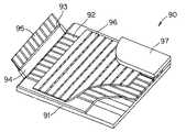
また、この他の平面表示素子として、下記の文献に記載されたものがある。Waveguide Panel Display Using Electromechanical Spatial Modulators, 1998SID International Symposium Digest of Technical Papers, p.1022-p.1025.上記文献の平面表示素子の構成は、図30に示すように、前面ガラス91の上に平行な複数の導光路92を並設し、その一端側には、マイクロレンズ93を有した導光材94を介してLED(ライトエミッティグダイオード)アレイ95を接続してある。LEDアレイ95は、複数の発光部が一次元に並べられたもので、その発光部の一つ一つが各導光路92それぞれに対応している。導光路92の上には、間隙を有して平行な複数の可撓薄膜(光スイッチ)96を、導光路92に直交する方向で並設してある。可撓薄膜96の上には一部分のみを可撓薄膜96に接触させた後面ガラス97を設けてあり、後面ガラス97はこの可撓薄膜96を変位可能に支持している。
【0010】
このように構成された平面表示素子90は、図31に示すように、所定の可撓薄膜96上の電極に電圧が印加されると、静電気応力によって可撓薄膜96が導光路92側に接近する方向に変位する。一方、LEDアレイ95は、画像信号に基づきこれと同期して発光する。すると、導光路92内を全反射しながら進んでいた光が可撓薄膜96内に導入され、可撓薄膜96内に設けられているミラー98に反射され、導光路92に略垂直な方向で再び入射されることになる。導光路92に略垂直な方向で入射された光は、全反射条件を満足する入射角度が保てず、導光路92を通過して前面ガラス91側から出射されることになる。
【0011】
この平面表示素子90によれば、静電気応力によって可撓薄膜96を変位させるため、可撓薄膜96の動作を高速追従させることができると共に、液晶表示装置のように光を多数層に透過せず、また、プラズマ表示装置のように放電部の隔壁形成や高圧駆動回路も不要になるため、高速で安価な平面表示素子の実現が可能になる。
【0012】
【発明が解決しようとする課題】
しかしながら、上述の光導波路タイプの平面表示素子80,90にあっては、入射光の導入方法が、導光板の片面側端部に接続されたプリズムを通じて導入する、或いは導光板・導波路の端面側からの導入方式となっている。ところが、薄型平板状の導光板・導波路は、その端面の入射開口面積が狭く、入射光との結合効率が悪くなる傾向がある。また、導光板・導波路は、更なる薄型化・大面積化が望まれており、端面の入射開口面積はますます狭くなる傾向にあり、結合効率の悪化が懸念されている。さらに、入射光(光源)形状、導入位置に制限があり、光源の大きさ・数が限られ、高出力の光を導入することができない。また、入射光形状をビーム状・線状にする必要があり、光源の種類が限られ、上記形状にするための光学系が別途必要となる。その結果、製造プロセスが複雑化してコストが増大するといった問題を生じる。
【0013】
そして、画像表示時においては、平面表示素子80では、導光路の光路上流の素子がON状態になると、この素子の光路下流への導光が減衰し、所謂クロストークが発生して画像品質を低下させることになる。また、ON状態の素子が生じるリーク光によって、その素子周囲の画像のコントラストが低下するという問題もある。一方、平面表示素子90では、細い導光路に大出力の光を投入するため、光路に光結合損失が発生して光利用効率が低下する。さらに導波路の一部に僅かでも欠陥がある場合には、その位置からリーク光が生じてしまい、画質低下の生じやすい構成となっている。
【0014】
本発明は、上記従来の問題に鑑みてなされたもので、導波路や導光板を用いた表示方式を用いることなく、任意のバックライト光源が使用でき、低コストでコントラスト低下を防止しつつ、エネルギ効率を高め、高品位な画像表示が行える表示素子、並びに露光処理が行える露光素子を提供することを目的としている。
【0015】
【課題を解決するための手段】
上記目的達成のため、本発明に係る請求項1記載の表示素子は、平面形状の光変調素子を含む表示素子であって、前記光変調素子に面状の入射光を導入する光源と、前記導入された入射光の少なくとも一部が、前記光変調素子を構成する層の界面で全反射する一方、入射光導入側の反対側からは前記入射光が実質的に出射しない特性を有する全反射光学部材と、前記全反射光学部材の全反射面側に配設すると共に前記全反射面から入射光を選択的に結合させて取り出す光結合要素とを備え、前記全反射光学部材は、該全反射光学部材内に光路を選択する光学要素が配置され、前記全反射光学部材に導入された面状の入射光の少なくとも一部が前記光路を選択する光学要素に導入され、該光路を選択する光学要素から出射される透過光の実質的全てが、前記光路を選択する光学要素より入射光光路前方の層の界面又は前記光路を選択する光学要素の入射光光路前方の界面における全反射臨界角より大きい角度成分を有し、その他の角度成分の入射光は反射されて透過されない性質を有し、前記光路を選択する光学要素が、誘電体多層膜を含む光干渉フィルタ、或いはコレステリック液晶または体積ホログラムのいずれかを含むブラッグ反射フィルタであり、前記全反射光学部材を構成する層が、前記入射光の波長域に対して吸収が実質的にないことを特徴とする。
【0016】
この表示素子では、導入された入射光が全反射光学部材に照射され、全反射光学部材内に導入されると、その導入された入射光の少なくとも一部が光変調素子の構成する層の界面で全反射する一方、入射光導入側の反対側からは入射光が実質的に出射されなくなる。この全反射光学部材の全反射面に入射光を結合させて取り出す光結合要素を選択的に近接配置することにより、近接配置された光結合要素に全反射光が取り出されて入射光光路前方に出射される。これにより、面状の入射光を高効率で光変調素子に導入でき、光結合要素の近接配置状態に応じた選択的な光変調が行える。
また、この表示素子では、光変調素子内に入射光の光路を選択する光学要素が配置され、この光路を選択する光学要素へ面状に入射光を導入する。導入された面状の入射光は、光路を選択する光学要素によって入射光の光路が特定の方向或いは任意の方向に変化させられ、その実質的全てが光変調素子の構成する層の界面で全反射により反射される。このため、入射光の形状、導入位置、並びに光源の種類に制限を受けることなく、面状の入射光を面状のまま直接的に高効率で導入でき、所望の界面で面状の全反射光を高効率で得ることができる。また、入射角依存性がなく吸収のない反射体を構成することができ、光変調素子からの透過光が実質的に生じないため、光利用効率を高めることができる。
また、この表示素子では、誘電体多層膜を含む光干渉フィルタを用いることにより、大面積かつ簡単な構成で任意の波長選択反射膜が形成でき、その反射波長の入射角依存性を利用して容易に光路を選択する光学要素を形成することができる。また、コレステリック液晶、体積ホログラムを含むブラッグ反射フィルタを用いることにより、低コストで光路を選択する光学要素を形成できる。
【0017】
請求項2記載の表示素子は、平面形状の光変調素子を含む表示素子であって、前記光変調素子に面状の入射光を導入する光源と、前記導入された入射光の少なくとも一部が、前記光変調素子を構成する層の界面で全反射する一方、入射光導入側の反対側からは前記入射光が実質的に出射しない特性を有する全反射光学部材と、前記全反射光学部材の全反射面側に配設すると共に前記全反射面から入射光を選択的に結合させて取り出す光結合要素とを備え、前記全反射光学部材は、該全反射光学部材の厚さ方向の入射光導入側から、光路を変化させる光学要素と、光路を選択する光学要素とがこの順で配置され、前記光路を変化させる光学要素へ面状に導入された入射光の少なくとも一部が前記光路を選択する光学要素に導入され、該光路を選択する光学要素から出射される透過光の実質的全てが、前記光路を選択する光学要素より入射光光路前方の層の界面又は前記光路を選択する光学要素の入射光光路前方の界面における全反射臨界角より大きい角度成分を有し、その他の角度成分の入射光は反射されて透過されない性質を有し、前記光路を選択する光学要素が、誘電体多層膜を含む光干渉フィルタ、或いはコレステリック液晶または体積ホログラムのいずれかを含むブラッグ反射フィルタであり、前記全反射光学部材を構成する層が、前記入射光の波長域に対して吸収が実質的にないことを特徴とする。
【0018】
この表示素子では、導入された入射光が全反射光学部材に照射され、全反射光学部材内に導入されると、その導入された入射光の少なくとも一部が光変調素子の構成する層の界面で全反射する一方、入射光導入側の反対側からは入射光が実質的に出射されなくなる。この全反射光学部材の全反射面に入射光を結合させて取り出す光結合要素を選択的に近接配置することにより、近接配置された光結合要素に全反射光が取り出されて入射光光路前方に出射される。これにより、面状の入射光を高効率で光変調素子に導入でき、光結合要素の近接配置状態に応じた選択的な光変調が行える。
また、この表示素子では、光変調素子の厚さ方向の入射光導入側から、光路を変化させる光学要素と、光路を選択する光学要素とがこの順で配置され、光路を変化させる光学要素へ面状に入射光を導入する。導入された入射光は、光路を変化させる光学要素によって入射光の光路が特定の方向或いは任意の方向に変化させられ、さらに光路を選択する光学要素によって特定の方向の入射光のみを透過させる。これにより、光変調素子に導入された光の実質的全てが光変調素子の構成する層の界面で全反射により反射される。このため、入射光の形状、導入位置、並びに光源の種類に制限を受けることなく、面状の入射光を面状のまま直接的に高効率で導入でき、所望の界面で面状の全反射光を高効率で得ることができる。また、入射角依存性がなく吸収のない反射体を構成することができ、光変調素子からの透過光が実質的に生じないため、光利用効率を高めることができる。
また、この表示素子では、誘電体多層膜を含む光干渉フィルタを用いることにより、大面積かつ簡単な構成で任意の波長選択反射膜が形成でき、その反射波長の入射角依存性を利用して容易に光路を選択する光学要素を形成することができる。また、コレステリック液晶、体積ホログラムを含むブラッグ反射フィルタを用いることにより、低コストで光路を選択する光学要素を形成できる。
【0019】
請求項3記載の表示素子は、前記光結合要素が、前記全反射面の入射光全反射条件を変化させることで入射光を取り出すことを特徴とする。
【0020】
この表示素子では、光結合要素が全反射光学部材の全反射面に近接配置されることで、全反射面における全反射条件が変化して、全反射光学部材内に導入された入射光が光結合要素にカップリングされて取り出される。
【0021】
請求項4記載の表示素子は、前記光結合要素が、電気機械動作により前記全反射光学部材の全反射面に近接可能に支持された可撓薄膜からなることを特徴とする。
【0022】
この表示素子では、電圧印加による静電気力を利用する方式、電圧印加による圧電効果を利用する方式、電流印加による電磁気力を利用する方式等の種々の方式により、光結合要素を全反射光学部材の全反射面に近接させる構成とすることで、省電力で応答性に優れた光スイッチを実現できる。
【0023】
請求項5記載の表示素子は、前記電気機械動作が、静電気力を駆動源とした動作であることを特徴とする。
【0024】
この表示素子では、光結合要素を静電気力により駆動することにより、全反射光学部材の全反射面に対して可撓薄膜を数μm以下の距離に近接させる構成にすることで、低電圧・低消費電力で高速駆動が可能となる。
【0025】
請求項6記載の表示素子は、前記光結合要素が、電界の印加により光学特性を変化させる液晶を含む層からなることを特徴とする。
【0026】
この表示素子では、光結合要素を電界の印加により液晶の光学特性を変化させ、全反射条件を変化させることにより、安価な構成で光スイッチング動作を得ることができる。
【0027】
請求項7記載の表示素子は、前記光結合要素が、前記全反射光学部材上に1次元アレイ状に配列されていることを特徴とする。
【0028】
この表示素子では、光結合要素を全反射光学部材上に1次元アレイ状に配列して構成することにより、1次元の同時変調可能な光変調素子を形成できる。
【0029】
請求項8記載の表示素子は、前記光結合要素が、前記全反射光学部材上に2次元アレイ状に配列されていることを特徴とする。
【0030】
この表示素子では、光結合要素を全反射光学部材上に2次元アレイ状に配列して構成することにより、2次元の同時変調可能な光変調素子を形成でき、画像表示を行うことができる。
【0031】
請求項9記載の表示素子は、前記光結合要素が、パッシブマトリクス駆動手段に接続されていることを特徴とする。
【0032】
この表示素子では、特に光結合要素が静電気力を利用したものであって、例えば、全反射光学部材の全反射面側に設けた電極と、一部が支持された可撓薄膜上に設けた電極との間に電圧を印加すると、可撓薄膜が全反射光学部材の全反射面側に向かって変位するが、このときの可撓薄膜の形状と弾性定数等の機械的物性、可撓薄膜と全反射面との空隙距離等を適宜選択することで、印加電圧に対する変位特性にヒステリシスが生じる。このヒステリシス特性を利用して、例えば、複数のストライプ状の電極を全反射光学部材の全反射面側に配置して信号電極とし、これと直交する複数のストライプ状の電極を可撓薄膜上に並設して走査電極とし、これら信号電極と走査電極に適宜電位を印加することにより、TFT等のアクティブ素子を用いることなく、2次元配列された任意の画素の透過率を高コントラストで制御することが可能となる。即ち、所謂パッシブマトリクス駆動が可能となり、これにより、安価で大面積な光変調素子を実現できる。
【0033】
請求項10記載の表示素子は、前記光結合要素が、取り出した光の光路を変化させる光路変更手段を有することを特徴とする。
【0034】
この表示素子では、光結合要素が取り出した光の光路を変化させることにより、光学素子からの出射光を特定の方向に集光させたり、拡散させたりすることが可能となる。
【0035】
請求項11記載の表示素子は、前記光路変更手段が、屈折により前記取り出した光の光路を変化させることを特徴とする。
【0036】
この表示素子では、光結合要素から取り出した光の光路を屈折により変化させることで、光量を維持したまま光路を変更することができる。
【0037】
請求項12記載の表示素子は、前記光路変更手段が、レンズアレイ、プリズムアレイ、屈折率分布レンズ体のいずれかからなることを特徴とする。
【0038】
この表示素子では、量産に適したレンズアレイ、プリズムアレイ、屈折率分布レンズ体による光学要素を適宜選定することにより、コストダウンを図りつつ良好な性能を発揮することができる。
【0039】
請求項13記載の表示素子は、前記光路変更手段が、回折により前記取り出した光の光路を変化させることを特徴とする。
【0040】
この表示素子では、光結合要素から取り出した光の光路を回折により変化させることで、光の光路を高精度に設定できる。
【0041】
請求項14記載の表示素子は、前記光路変更手段が、体積ホログラム、位相変調型回折格子、振幅変調型回折格子のいずれかからなることを特徴とする。
【0042】
この表示素子では、例えばフォトポリマー法や射出成形法によって大量転写生産が可能となり、光学素子自体のコストダウンが図れる。
【0043】
請求項15記載の表示素子は、前記光路変更手段が、光拡散又は光散乱により前記取り出した光の光路を変化させることを特徴とする。
【0044】
この表示素子では、光拡散又は光散乱により光路を変化させることで、取り出した光を任意の方向に出射させることができる。
【0045】
請求項16記載の表示素子は、前記光路変更手段が、多孔質体、異種屈折率分散体又は分布体、表面に凹凸を有する光拡散体又は光散乱体のいずれかであることを特徴とする。
【0046】
この表示素子では、量産に適した多孔質体、異種屈折率分散体又は分布体、光拡散体又は光散乱体を適宜選定することにより、光学素子自体のコストダウンが図れる。
【0047】
請求項17記載の表示素子は、前記光結合要素が、取り出した光の特定波長成分を吸収して出射する特定波長成分吸収手段を有することを特徴とする。
【0048】
この表示素子では、取り出した光の波長成分のうち、特定波長成分を吸収して出射させることにより、同一種の入射光であっても複数色の出射光を選択的に得ることができる。
【0049】
請求項18記載の表示素子は、前記光結合要素が、取り出した光を受けて励起発光する蛍光体を有することを特徴とする。
【0050】
この表示素子では、取り出した光により励起発光する蛍光体を有することで、蛍光体の発色により複数色の出射光を選択的に得ることができる。
【0051】
請求項19記載の表示素子は、前記光結合要素により取り出された出射光を受けて励起発光する蛍光体を有することを特徴とする。
【0052】
この表示素子では、例えば光結合要素の光路前方に蛍光体を配置して、光結合要素から取り出された出射光を任意の波長に変換することができる。
【0053】
請求項20記載の表示素子は、前記光路を変化させる光学要素と前記光路を選択する光学要素とが、光学的に接触していることを特徴とする。
【0054】
この表示素子では、光路を変化させる光学要素と、光路を選択する光学要素とが光学的に接触していることにより、双方の光のカップリング性を良好にできると共に、光路を変化させる光学要素が方向性を有する場合に、入射光を光路を変化させる光学要素から入射角度成分を保持させたまま光路を選択する光学要素に導入することができる。
【0055】
請求項21記載の表示素子は、前記光路を変化させる光学要素と前記光路を選択する光学要素とが、屈折率が1より大きい媒質を介して光学的に接触していることを特徴とする。
【0056】
この表示素子では、光路を変化させる光学要素と、光路を選択する光学要素とが屈折率が1より大きい媒質を介して光学的に接触することにより、この媒質との界面で全反射を生じさせることなく、光路を変化させる光学要素から光路を選択する光学要素へ入射光を導入できる。
【0057】
請求項22記載の表示素子は、全反射光学部材の一部を構成する透明媒質を備え、該透明媒質の光路前方に前記光路を変化させる光学要素を配置したことを特徴とする。
【0058】
この表示素子では、入射光が透明媒質を透過した後に光路を変化させる光学要素に導入されて、特定の方向の入射光のみ透過される。
【0059】
請求項23記載の表示素子は、全反射光学部材の一部を構成する透明媒質を備え、該透明媒質の光路前方に前記光路を選択する光学要素を配置したことを特徴とする。
【0060】
この表示素子では、入射光が透明媒質を透過した後に光路を選択する光学要素に導入されて、特定の方向の入射光のみ透過される。
【0061】
請求項24記載の表示素子は、全反射光学部材の一部を構成する透明媒質を備え、該透明媒質の光路前方に前記光路を変化させる光学要素と前記光路を選択する光学要素をこの順で配置したことを特徴とする。
【0062】
この表示素子では、入射光が透明媒質を透過した後に光路を変化させる光学要素に導入され、入射光の光路が特定の方向或いは任意の方向に変化させられ、さらに、光路を選択する光学要素に導入され、特定の方向の入射光のみ透過される。
【0063】
請求項25記載の表示素子は、前記光路を変化させる光学要素が、該光路を変化させる光学要素の平均屈折率をnt、光路前方の全反射界面の前方側媒質の屈折率をnw、光路を変化させる光学要素の媒質内を進む光の角度をθtとしたときに、少なくとも、sinθt>nw/nt の条件を満たす角度θtの光を含んで前方に出力することを特徴とする。
【0064】
この光変調素子では、少なくとも、sinθt>nw/ntの条件を満たす角度θtの光が光路を変化させる光学要素を透過して、光路を変化させつつ前方に出力される。
【0065】
請求項26記載の表示素子は、前記光路を変化させる光学要素が、屈折により光路を変化させるものであることを特徴とする。
【0066】
この表示素子では、光路を変化させる光学要素が、入射光の光路を屈折により変化させることにより、入射光の強度を実質的に低下させることなく光変調素子へ導入できる。
【0067】
請求項27記載の表示素子は、前記光路を変化させる光学要素が、レンズアレイ、プリズムアレイ、異なる屈折率が分布した異種屈折率分布体のいずれかであることを特徴とする。
【0068】
この表示素子では、量産に適したレンズアレイ、プリズムアレイ、異種屈折率分布体による光学要素を適宜選定することにより、コストダウンを図りつつ良好な性能を発揮することができる。
【0069】
請求項28記載の表示素子は、前記光路を変化させる光学要素が、回折により光路を変化させるものであることを特徴とする。
【0070】
この表示素子では、光路を変化させる光学要素が、入射光の光路を例えば透過型回折格子による回折によって変化させることにより、高精度な入射角度で入射光を光変調素子へ導入できる。
【0071】
請求項29記載の表示素子は、前記光路を変化させる光学要素が、体積ホログラム、位相変調型回折格子、振幅変調型回折格子のいずれかであることを特徴とする。
【0072】
この表示素子では、例えばフォトポリマー法や射出成形法によって大量転写生産が可能となり、光変調素子自体のコストダウンが図れる。
【0073】
請求項30記載の表示素子は、前記光路を変化させる光学要素が、光拡散により光路を変化させるものであることを特徴とする。
【0074】
この表示素子では、光路を変化させる光学要素が、光拡散により光路を変化させることで、入射光を任意の方向から光変調素子へ入射させることができる。
【0075】
請求項31記載の表示素子は、前記光路を変化させる光学要素が、多孔質体、異種屈折率分布体又は分散体、表面に凹凸を有する拡散体又は散乱体のいずれかであることを特徴とする。
【0076】
この表示素子では、量産に適した多孔質体、異種屈折率分布体又は分散体、拡散体による光学要素を適宜選定することにより、コストダウンを図りつつ良好な性能を発揮することができる。
【0077】
請求項32記載の表示素子は、前記光路を変化させる光学要素が、光反射により光路を変化させるものであることを特徴とする。
【0078】
この表示素子では、光路を変化させる光学要素が、光反射によって光路を変化させることで、入射光を任意の方向から光変調素子へ入射させることができる。
【0079】
請求項33記載の表示素子は、前記光路を選択する光学要素が、該光路を選択する光学要素の平均屈折率をns、光路前方の全反射界面の前方側媒質の屈折率をnw、光路を選択する光学要素の媒質内を進む光の角度をθsとしたときに、sinθs>nw/nsの条件を満たす角度θsの光を実質的全て透過させることを特徴とする。
【0080】
この表示素子では、sinθs>nw/nsの条件を満たす角度θsの光が光路を選択する光学要素を実質的全て透過して、他の光は反射されることにより、特定の光成分のみ選択的に透過される。
【0081】
請求項34記載の表示素子は、前記光路を選択する光学要素が、入射光の波長域に対して選択的に反射する機能を有し、前記光路を選択する光学要素への入射光の入射角が該光学要素の面に対して浅い角度となるに従って、選択的に反射される入射光の波長が短波長側にシフトすることを特徴とする。
【0082】
この表示素子では、光路を選択する光学要素が、入射光の波長域に対して選択的に反射する機能を有し、この光学要素への入射光の入射角が該光学要素の面に対して浅い角度となるに従って、選択的に反射される入射光の波長が短波長側にシフトする。この性質を利用して、所定の入射角成分の入射光だけが透過するように光路を選択する光学要素を設計し、全反射の生じる入射角度成分の入射光だけを選択的に抽出することを可能にできる。
【0083】
請求項35記載の表示素子は、前記光路を選択する光学要素への入射光の入射角が、入射光光路前方の全反射界面への入射角を全反射臨界角以下にするときに、前記光路を選択する光学要素が前記入射光の実質的全てを選択的に反射することを特徴とする。
【0084】
この表示素子では、光路を選択する光学要素への入射光の入射角が、この入射角と各層の屈折条件により変化する入射光光路前方の全反射界面への入射角をこの全反射界面における全反射臨界角以下にするときに、光路を選択する光学要素が入射光の実質的全てを選択的に反射する。これにより、全反射界面において全反射されない角度成分の入射光が選択的に反射されて光路前方に透過されなくなる。
【0085】
請求項36記載の表示素子は、前記全反射された入射光の実質的全てが前記全反射光学部材の入射光導入側に戻ることを特徴とする。
【0086】
この表示素子では、全反射された入射光の実質的全てが光変調素子の入射光導入側に戻ることにより、全反射面を有する媒質内において、導光、蓄積、閉じ込め等が行われることが実質的にない。
【0087】
請求項37記載の表示素子は、前記入射光が、任意の入射角を有する拡散光であることを特徴とする。
【0088】
この表示素子では、入射光が任意の入射角を有する拡散光であることにより、種々の方向からの入射光を光変調素子に導入でき、入射光の均一性を向上できる。
【0089】
請求項38記載の表示素子は、前記光結合要素又はその光路前方に蛍光体を有し、前記全反射光学部材の全反射面と前記光結合要素との間に、前記蛍光体の発光波長成分を反射すると共に前記入射光の波長成分を透過させる光学フィルタが介装されていることを特徴とする。
【0090】
この表示素子では、入射光が光学フィルタを透過して蛍光体に照射することにより蛍光体が発光する。この蛍光体の発光した光のうち、光路後方に向けて発した光が光学フィルタによって光路前方に反射されて出射される。これにより、光利用効率が向上し、より高輝度の表示が可能となる。
【0091】
請求項39記載の表示素子は、前記光結合要素又はその光路前方に蛍光体を有し、前記蛍光体の光路前方に前記蛍光体の発光波長成分を透過すると共に、前記入射光の波長成分を遮光させる光学フィルタが設けられていることを特徴とする。
【0092】
この表示素子では、例えば入射光としてUV光を用いた場合に、その透過光(漏れ光)が表示側(観測者側)へ出射されることを防止できる。
【0093】
請求項40記載の表示素子は、前記光結合要素又はその光路前方に蛍光体を有し、前記蛍光体の光路前方に前記蛍光体の発光波長域の光を吸収する光学フィルタが設けられていることを特徴とする。
【0094】
この表示素子では、例えば蛍光体の発光波長が可視光域の場合、可視光を吸収するNDフィルタ(透過率20〜70%程度)を表示側(観測者側)に設けることにより、明るい場所であっても高いコントラストで表示が行える。
【0095】
請求項41記載の表示素子は、前記光学フィルタが、誘電体多層膜を含む光干渉フィルタであることを特徴とする。
【0096】
この表示素子では、誘電体多層膜を含む光干渉フィルタを用いることにより、大面積かつ簡単な構成で任意の波長選択反射膜が形成でき、その反射波長の入射角依存性を利用して容易に光学フィルタを形成することができる。
【0097】
請求項42記載の表示素子は、前記光学フィルタが、コレステリック膜を含むブラッグ反射フィルタであることを特徴とする。
【0098】
この表示素子では、コレステリック液晶を含むブラッグ反射フィルタを用いることにより、低コストで光学フィルタを形成できる。
【0099】
請求項43記載の表示素子は、前記入射光の主な波長が、350nm〜400nmであることを特徴とする。
【0100】
この表示素子では、入射光の主な波長を350nm〜400nmとすることにより、蛍光体の発光輝度を高めることができ、より高輝度の画像表示が可能となる。
【0101】
請求項44記載の表示素子は、前記入射光の主な波長が、400nm〜500nmであることを特徴とする。
【0102】
この表示素子では、入射光の主な波長を400nm〜500nmとすることにより、UV光に耐性のない有機材料等を用いて表示素子を構成することができる。
【0103】
請求項45記載の表示素子は、前記蛍光体が、可視光を発光することを特徴とする。
【0104】
この表示素子では、蛍光体が可視光を発光することにより、UV光の光源から可視光の表示を行うことができる。
【0105】
請求項46記載の表示素子は、前記蛍光体が、赤色、緑色、青色に発光する発光体を形成したものであることを特徴とする。
【0106】
この表示素子では、形成された赤色、緑色、青色の蛍光体が発光することにより、フルカラー画像を表示させることができる。
【0107】
請求項47記載の表示素子は、前記平面光源が前記全反射光学部材の内部に備わる光源であって、前記入射光が前記光源から出射される光であることを特徴とする。
【0108】
この表示素子では、光源を全反射光学部材の内部に備えることにより、光源から出射された光が光変調素子内部に直接的に導入され、入射光導入の際の損失が大幅に低減される。
【0109】
請求項48記載の表示素子は、前記入射光が、前記全反射光学部材の外部から入射されることを特徴とする。
【0110】
この表示素子では、全反射光学部材の外部から入射光を導入することにより、表示素子の設計自由度が向上し、大型の光源であっても利用することができ、高出力化が容易に行える。
【0111】
請求項49記載の表示素子は、前記表示素子の入射光導入側に対峙して設けられ、前記表示素子に導入した後に該表示素子により反射された入射光を表示素子側へ再投入する反射体を備えたことを特徴とする。
【0112】
この表示素子では、表示素子の入射光導入側に対峙して反射体を設けることにより、表示素子に一旦入射され該表示素子により反射された入射光が反射体に照射され、さらにこの反射体からの反射光が表示素子側へ再投入されるため、光のリサイクルが行われ、光利用効率が向上して高効率化が図られる。
【0113】
請求項50記載の露光素子は、請求項1〜請求項49のいずれか1項記載の表示素子を用い、露光データに基づき光変調して露光対象に向けて選択的に光を出射することを特徴とする。
【0114】
この露光素子では、請求項1〜請求項49のいずれか1項記載の表示素子を用い、予め設定された露光データに基づき光変調することで、露光対象に向けて選択的に光が出射され、露光対象に露光処理を施すことができる。
【0115】
【発明の実施の形態】
以下、本発明に係る表示素子及び露光素子の好適な実施の形態を図面を参照して詳細に説明する。図1に本発明に係る光変調素子の搭載された表示素子の概念的な構成を示した。本実施形態の表示素子100は、平面形状の全反射光学部材2と、この全反射光学部材2へ面状の光を導入する平面光源4と、全反射光学部材2の入射光導入側とは反対側の面に近接可能に配置され可撓薄膜からなる光結合要素6を有してなる。全反射光学部材2と光結合要素6とは光変調素子を構成している。この全反射光学部材2は、面状の入射光を導入したときに、この導入した入射光が全反射光学部材2の光路前方の面(全反射面22)で全反射により反射されるように形成されている。そして、全反射光学部材2の光結合要素6が近接配置された領域では、全反射面22における入射光の全反射条件が崩れ、光結合要素6に入射光が結合して取り出されて光路前方に出射される。一方、全反射光学部材2の全反射面22で光結合要素6が近接していない領域では、入射光が全反射され、実質的にこの全反射光学部材2を透過して光路前方に出射することはない。
【0116】
上記光結合要素6は、全反射光学部材2の全反射面22に接触する位置に移動可能に設けられるが、全反射面22に完全に接触させなくても十分に近接させるだけでもよい。この場合の近接距離はλ/10(λは波長)程度以下とすることで、接触時と同様な近接場光結合を生じさせることができる。従って、上記表示素子100によれば、平面光源4から面状の光を全反射光学部材2に導入し、光結合要素6を全反射光学部材2の全反射面22に選択的に近接させることで、この近接させた光結合要素6から光を光路前方に出射させ、所望の表示を行うことができる。
【0117】
以下に上記表示素子100の各構成要素について詳細に説明する。まず、全反射光学部材2を説明する。図2に全反射光学部材2の具体的な一構成例を示した。図2に示すように全反射光学部材2は、入射光の導入側から光路を変化させる光学要素10、光路を選択する光学要素12、透明媒質14の順で積層された多層構造体となっている。この全反射光学部材2の透明媒質14の光路前方には透明媒質16(本実施形態では空気)が存在し、透明媒質14の屈折率n1(第1の屈折率)と透明媒質16の屈折率n2(第2の屈折率)との関係は、透明媒質14と透明媒質16との界面となる全反射面22における全反射条件を満足するように設定されている。例えば透明媒質14がガラス基板の場合は屈折率n1=1.5で、透明媒質16が空気の場合は屈折率n2=1.0となる。なお、全反射光学部材2を構成する各層は、入射光の波長域に対して実質的に吸収されることがなく、入射光及び全反射面22で全反射された入射光の損失を抑止して高効率な光学部材を構成している。
【0118】
光路を変化させる光学要素10は、屈折、回折、光拡散、光反射等を利用して光路を変化させる光学要素であり、一例として次の種類の光学要素を使用できる。屈折を利用する場合は、レンズアレイ、プリズムアレイ、屈折率分散体等が用いられ、入射光の強度が実質的に低下しない。回折を利用する場合は、図3に示す透過型の回折格子が用いられ、体積ホログラム(図3(a)参照)、レリーフ型回折格子(図3(b)参照)や屈折率変調型回折格子(図3(c)参照)等の位相変調型回折格子、振幅変調型回折格子等が用いられ、高精度に入射光光路の角度を設定できる。各光学要素は、例えばフォトポリマー法や射出成形法によって大量転写生産が可能である。
【0119】
また、光拡散を利用する場合は、図4に示す光拡散板が用いられ、多孔質体(図4(a)参照)、異なる屈折率を有する物質20が分布・分散した異種屈折率分布体・分散体(図4(b)参照)、表面が凹凸に形成された光拡散体又は散乱体(図4(c)参照)等が用いられる。さらに、光反射を利用する場合は、任意の方向に反射する微小反射体の分散体等が用いられる。いずれの光学要素も量産に適しており、容易にコストダウンが可能である。
【0120】
光路を選択する光学要素12は、この光学要素12から出射される選択透過光の実質的全てが、入射光光路前方の層における全反射臨界角より大きい角度成分を有し、その他の角度成分の入射光は選択的に反射されて透過されないものである。即ち、透明媒質14と透明媒質16との界面で全反射を生じさせる条件である全反射臨界角θCより大きい角度成分の入射光だけが光路を選択する光学要素12を透過し、他の角度成分の入射光に対しては遮光される。なお、全反射臨界角θCは(1)式により求められる。
θC=sin-1(n2/n1) (1)
【0121】
具体的な光路を選択する光学要素12の一構成例としては、誘電体多層膜からなる光干渉フィルタが挙げられる。この光干渉フィルタの層構成を図5に示した。光干渉フィルタは、高屈折率材料と低屈折率材料を順次積層して構成された誘電体多層膜であって、その光学特性としては、詳細は後述するが、入射光をその波長によって選択的に反射する機能を有し、入射角に応じて選択反射する波長が短波長側にシフトする特性を有する。いま、入射光の波長域をλiS〜λiL(λiS<λiL)としたとき、光学要素12から出射される選択透過光の出射角が全反射臨界角θC以下の角度成分の光に対しては、波長域λiS〜λiLの入射光の実質的全てを選択的に反射する。この構成によれば、大面積かつ簡単な構成で任意の波長選択が可能な反射膜が形成でき、その反射波長の入射角依存性を利用して容易に光路を選択する光学要素12を形成することができる。なお、上記光干渉フィルタは、誘電体多層膜の層構成に金属膜を追加した金属/誘電体多層膜としてもよい。なお、誘電体多層膜等からなる光干渉フィルタは、EB蒸着(電子ビーム共蒸着)、スパッタ等で透明支持基板上に複数の薄膜材料を成膜することで形成可能である。また、前記薄膜材料は、異なる屈折率を有する有機多層膜、又は無機物を含有する有機多層膜でもよく、この場合は塗布、ラミネート等により、より低コストで形成可能である。
【0122】
ここで、光路を変化させる光学要素10と光路を選択する光学要素12の光学的性質について詳述する。まず、光路を変化させる光学要素10が、例えば屈折により光路を変化させる場合を考える。図6に示すように、光路を変化させる光学要素(平均屈折率nt)、光路を選択する光学要素(平均屈折率ns)、透明媒質u(平均屈折率nu)、透明媒質v(平均屈折率nv)、全反射面の前方側の透明媒質w(平均屈折率nw)がこの順で配置された光学素子の場合、透明媒質vと透明媒質wとの界面が全反射面とすると、各々の界面での入射角と各媒質の平均屈折率の関係は(2)式のように表せる。
【0123】
nv・sinθv=nw
nu・sinθu=nv・sinθv=nw
ns・sinθs=nu・sinθu=nw
nt・sinθt=ns・sinθs=nw (2)
ここで、θt、θs、θu、θvは、それぞれの媒質内での光路角度である。
【0124】
従って、光路を変化させる光学要素10の条件としては、sinθt>nw/ntの条件を満たす角度θtの光を少なくとも含んで光路前方に出力する必要がある。好ましくは、この条件を満たす角度θtの光をできる限り多く含んで光路前方に出力する。なお、透明媒質wが空気の場合はnw=1となり、上記条件は、sinθt>1/ntとなる。
【0125】
一方、光路を選択する光学要素12の条件としては、sinθs>nw/nsの条件を満たす光のみを透過させるように設定される。なお、透明媒質wが空気の場合はnw=1となり、上記条件は、sinθs>1/nsとなる。
【0126】
次に、平面光源4を説明する。平面光源4は、全反射光学部材2に面状の入射光を照射する。この入射光としては、コリメート光又は拡散光のいずれでも使用でき、また、全反射光学部材2の外部から入射する他に、全反射光学部材2内部に光源を有して発光させるものであってもよい。コリメート光の場合は、特定の入射角度成分の入射光を全反射光学部材2に供給することで光利用効率を向上できる一方、拡散光の場合は、任意の低コストな平面光源が使用できる。また、内部に光源を有する場合は、光源からの光が全反射光学部材2内部に直接的に導入されるため光の導入効率が向上し、光学素子と光源が一体形成できるため小型薄型化が図られる。一方、外部に光源を有する場合は、表示素子100の設計自由度が向上し、大型で任意の外部平面光源も利用することができ、高出力化が容易に行える。
【0127】
上記入射光としては、UV光、青色光や緑色光等の可視光、赤外光等の特定バンドの波長域の光が使用できる。また、光源の種類としては、例えば、不活性ガスや水銀蒸気を封入した電子管である蛍光灯、水銀灯、ネオン管灯、クルックス管等の一般的に用いられ且つそのまま利用できる放電ランプや、コリメート光が容易に得られるレーザ光源や、安価で波長域の定まったLEDや、面状光が得られる無機又は有機ELや、白色光を発して目的に応じてフィルタリングすることで任意の波長成分が取り出せる白熱ランプや、CRT等の陰極線表示管であって表示素子へ導入する面状光が直接的に得られる陰極線ランプや、同じく平面状の表示管であって面状光が直接的に得られるFED等が使用できる。
【0128】
上記平面光源は、直接面状光が得られるもの以外は、例えば、複数の点光源や線光源を集結させることで面状光を形成したり、1本又は複数本の光ビームを偏向走査させることで面状光を形成する。また、単に点光源や線光源からの光を、拡散・散乱、屈折、回折等を行うフィルタを通すことで面状光を形成して照射するものであってもよい。複数の点光源や線光源を集結させる方式としては、例えばLEDを縦横にマトリクス配置し、光量が均一となるように発光させる構成や、例えば蛍光管を並列配置させて発光させる構成のもの等が挙げられる。また、偏向走査させる方式としては、例えば半導体レーザやガスレーザ等のレーザビームを、ポリゴンミラー等により偏向走査させることで面状光を得る構成や、平面表示素子全体を真空封止して陰極線を走査させて蛍光体を励起発光させる構成のもの等が挙げられる。なお、レーザビームは複数の照射スポットを形成するマルチビームを用いることで、より効率的に面状光を得ることができる。いずれにせよ、平面光源と同等の面状光を得ることができれば点光源や線光源等のいずれの光源を用いることできる。
【0129】
さらに、光源からの光を全反射光学部材2に照射する際、予め面状光を形成して照射する以外にも、点光源や線光源による光をそのまま全反射光学部材2に対して順次走査させながら導入してもよい。この場合には、例えば上記したレーザビームの走査等が好適に利用できる。
【0130】
次に、光路を選択する光学要素12の特性を、図7〜図9を用いて詳細に説明する。図7は光学要素12への入射光の入射角を示しており、図8は入射光の波長に対する光学要素12の分光透過率を入射角毎に示したグラフで、図9は光学要素12内外の光路を示す図である。
【0131】
まず、図7に示すように、光学要素12へ入射光を各入射角θ0,θ1,θ2,θ3で入射させた場合を考えると、図8に示すように光学要素12の分光透過率が変化する。即ち、入射角が全反射臨界角θC以下のθ0(0度)の場合は、分光透過率が入射光の波長域λiS〜λiLに対して略0%となって遮光状態(透過せずに反射される状態)となる。一方、入射角が全反射臨界角度θCより大きい場合は、入射角がθ1,θ2,θ3と大きくなるに従って、分光透過率の透過特性が短波長側にシフトするため透過光量が増加する。即ち、光路を選択する光学要素12への入射光の入射角が該光学要素12の面に対して浅い角度となるに従って、選択的に反射される入射光の波長が短波長側にシフトする。これにより、入射光の入射角度成分がθ0の光は透過せず、入射角度成分が特定の角度より大きいθ1,θ2,θ3の光がこの順に多く透過するようになる。そこで、光学要素12を、その分光特性が、所定の界面における全反射臨界角θCより大きい入射光成分だけが透過するように設計することにより、全反射条件を満足しない入射光成分を遮光して、全反射する入射光成分だけを光学要素12から選択的に出射させることが可能となる。
【0132】
上記のように、全反射面22における全反射臨界角θCより大きい入射光成分だけが透過するように設計された光学要素12を用いて全反射光学部材2を構成した場合の入射光光路を、図9を用いて説明する。図9(a)は、光路を選択する光学要素12に入射された光が光学要素12で反射する光路Aと、光路を選択する光学要素12に入射された光が、光学要素12を透過して光路前方の透明媒質14と透明媒質16との界面となる全反射面22で全反射する光路Bとを示している。
【0133】
光路Aは、入射光の入射角θiが全反射面22における全反射臨界角θC以下の場合で、光学要素12は、このような入射角成分の光を透過させずにその表面で選択的に反射させる。このため、全反射臨界角θC以下の入射角度成分の光は光学要素12により光路前方に対して遮光される。光路Bは、入射光の入射角θiが全反射面22における全反射臨界角θCより大きい場合で、光学要素12は、このような入射角成分の光を透過させる。このため、全反射臨界角θCより大きい入射角度成分の光は光学要素12を透過して透明媒質14に導入され、全反射面22で全反射される。なお、図9(a)は、入射光が入射される側の屈折率naと透明媒質14の屈折率nbが等しく、光学要素12に対する入射角θiと全反射面22における入射角θSとが等しい場合を示している。
【0134】
一方、図9(b)は、入射光が入射される側の屈折率naと透明媒質14の屈折率nbが異なり、光学要素12に対する入射角θiと全反射面22における入射角θSとが異なる場合を示している。この場合の光学要素12は、全反射面22における入射角θSが全反射臨界角θCより大きくなるように設計される。
【0135】
上記のように設計された光路を選択する光学要素12を用いて全反射光学部材2を構成することにより、図1に矢印で光路を示すように、全反射光学部材2に導入されたコリメート光又は拡散光からなる面状の入射光が光路を変化させる光学要素10に入射されると、光の照射位置から拡散等により光路が変化する。そして、光路の変化した光が光路を選択する光学要素12に到達すると、透明媒質14と透明媒質16との界面となる全反射面22における全反射臨界角θCより大きい角度成分の入射光だけが光学要素12を透過し、他の角度成分の入射光は光学要素12の表面で光入射側に選択的に反射される。
【0136】
従って、全反射光学部材2に入射される光のうち、全反射面22で全反射する光だけが光路前方に導入され、この導入された光が全反射面22で全反射する。即ち、光路を選択する光学要素12においては、光学要素12から出射される透過光の実質的全てが、光路を選択する光学要素12より入射光光路前方の全反射面における全反射臨界角より大きい角度成分を有し、その他の角度成分の入射光は選択的に反射されて透過されない。なお、全反射面を有する媒質内において、導光、蓄積、閉じ込め等が行われることは実質的にない。
【0137】
また、光路を選択する光学要素12の表面で入射光導入側に反射された光の一部は、光路を変化させる光学要素10の光入射側の界面(反射層)で反射され、再度、光路を選択する光学要素12に投入される。この再投入された光は入射角度が大きくなり、全反射臨界角θCより大きくなって、光学要素12を透過して透明媒質14に導入される。
【0138】
次に、光結合要素6を説明する。光結合要素6は、全反射面における入射光の全反射条件を崩し、光結合要素6に光を結合させて取り出し、光路前方に出射させるものである。この光結合要素6には、取り出した光の光路を変更する光路変更手段、特定波長成分を吸収する特定波長成分吸収手段が適宜設けられる。具体的には、例えば次の(1)〜(4)に示す種類のものが利用できる。
(1)屈折により光路を変更するもの又はその機能を有するもの全反射面22に近接配置させることで取り出した出力光を、屈折によりその光路を変更するものであって、例えば、図10(a)に示すレンズアレイ、図10(b)に示すプリズムアレイ、図10(c)に示す屈折率分布レンズ体等が挙げられる。これらのレンズアレイ、プリズムアレイによれば、全反射光学部材2の全反射面22から取り出した出力光を集光或いは拡散させて異なる方向に出射させることができ、出力光に出射方向性を持たせたり、出射方向性をなくすことを出力光の強度を低下させることなく簡単な構成で行える。
【0139】
(2)透過型回折格子又はその機能を有するもの取り出した光を透過させると共に回折により出射方向を変更する透過型回折格子としては、前述と同様の図3(a)に示す体積ホログラム、図3(b)に示すレリーフ型回折格子、図3(c)に示す屈折率変調型回折格子、また、振幅変調型回折格子等が挙げられる。これらの透過型回折格子によれば、出力光の出射角度を正確に設定することができる。また、例えばフォトポリマー法や射出成形法によって大量生産が可能となり、表示素子自体のコストダウンが図られる。
(3)光拡散体又は光散乱体或いはその機能を有するもの取り出した光を拡散又は散乱させる光拡散体又は光散乱体としては、図11(a)に示す量産に適した多孔質体、図11(b)に示す高屈折率微粒子等の異なる屈折率を有する物質20の分散体又は分布体、図11(c)に示す表面に凹凸が形成された光拡散体又は光散乱体等が挙げられる。これらの光拡散体又は光散乱体によれば、拡散又は散乱により出力光を任意の方向に散らすことができ、出力光の出射方向性をなくすことができる。
【0140】
(4)入射光を吸収するもの又はその機能を有するもの入射光を吸収するものとしては、画像データの記録された透過性画像フィルム等が挙げられる。全反射光学部材2の全反射面22から取り出した出力光を透過性画像フィルムにより特定波長成分を吸収させて出射することで、濃淡表示と特定色の発色を得ることができる。即ち、透過性画像フィルムに記録された画像様に表示が行える。このため、同一種の入射光であっても複数色の出射光を選択的に得ることができる。
【0141】
ここで、上述した全反射光学部材2,平面光源4,光結合要素6により構成した表示素子100の光変調動作を説明する。図1に示す全反射光学部材2に平面光源4からの光が導入されると、光路を変化させる光学要素10及び光路を選択する光学要素12を透過した光が全反射光学部材2の全反射面22で全反射されることになる。そして、この全反射面22に光結合要素6が近接した領域では、全反射面22における全反射条件が崩されて、光結合要素6に全反射面22から光が取り出される。取り出された光は全反射光学部材2とは反対側の表示側に出射され表示光となる。一方、光結合要素6が全反射面22から離間した領域では、全反射面22で全反射されて表示側に出射されることはない。このように、本実施形態の表示素子100は、光結合要素の構成が単純であるため、空隙ギャップ、膜均一性が大幅に低減でき、大面積化への実用性に優れた構成となっている。
【0142】
上記構成の表示素子100によれば、導光板や光導波路を使用することなく、低コストの構成で面状の光源からの入射光を面状のまま直接的に高効率で全反射光学部材2に導入するため、例えば入射光を端面側から導入する場合と比較して入射光の導入口を格段に広く採ることが可能となり、入射光との結合効率が向上し、表示素子100自体の薄型化に影響されることなく、高効率で面状の全反射光を導入することができる。これにより、光結合要素6が全反射面に近接配置された領域から、全反射面22から取り出された入射光を表示面側に高効率で出射することができる。従って、表示素子100の光路前方側の面では、光結合要素6の設けられた領域だけが光り、表示素子100から画像様に光が出射される。即ち、必要箇所だけに画像表示を行うことができる。また、この構成によれば、導光板や光導波路を使用する場合に生じるクロストークによる局所的な光量低下が防止され、表示画面の全面に亘って均等な明るさの表示が可能となる。
【0143】
そして、表示素子100内の各界面で反射される入射光の一部は、界面における反射等により光路前方に再投入されるため、表示素子100の高出力化も容易に達成できる。さらに、全反射光学部材2単体では透過光が実質的に生じないため、導入した光量が減衰することがなく、光利用効率を向上できる。なお、全反射光学部材2が空気(不活性ガスであってもよい)と接触する気体接触界面を全反射面とすることにより、全反射を生じさせる屈折率の層を別途設けることなく単純構造にできる。また、平面光源の配置位置が自在に選択でき、数多くの光源を実装することが可能となり、光の出射輝度を向上できる。さらに、平面光源の入射光角度分布制限がなく、既存のバックライト光源が使用可能となる。なお、図示は省略するが、表示素子100の入射光導入側に、この表示素子100により反射された入射光を表示素子100側に再投入するための反射体を設けてもよい。これにより、光のリサイクルが行われ、光利用効率が向上して高効率化が図られる。
【0144】
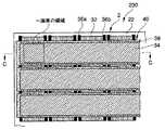
次に、上述した表示素子を2次元配列して構成した本発明の第2実施形態を図12,図13を用いて説明する。図12は可撓薄膜により形成した表示素子を2次元配列した平面表示素子の平面図で、図13は、図12のC−C断面図で(a)は非駆動時、(b)は駆動時の状態を示す図である。図12及び図13に示すように、本実施形態の平面表示素子200は、全反射光学部材2の全反射面22上に光結合要素6がm行n列(m、nは整数)の2次元状に配列されている。即ち、全反射面22上には入射光に対して透明な信号電極32が列方向にそれぞれn列平行配置され、この信号電極32に直交する行方向に、同じく入射光に対して透明な走査電極34が信号電極の両側方に形成された一対の柱材36a,36bを介してm行平行配置されている。なお、走査電極34の信号電極32側には、電気絶縁性を有する光拡散層38が形成され、走査電極34と光拡散層38により可撓薄膜を形成している。
【0145】
電気絶縁性を有する光拡散層は、例えばSiO2、SiNx等の無機絶縁膜や、ポリイミド等の有機絶縁膜が使用可能である。また、可撓薄膜と信号電極の間の空隙形成には、空隙部に予め犠牲層を形成し、その上に可撓薄膜を形成してから最後に犠牲層をエッチング除去して空隙を得ることができる。可撓薄膜に光拡散性を付与する手段としては、フォトリソ・エッチング等により表面に凹凸を形成する方法や、屈折率の異なる微粒子を上記絶縁膜に分散する方法等で得られる。
【0146】
上記構成の平面表示素子200の光変調動作を説明すると、まず、図13(a)に示すように、信号電極32と走査電極34との間の電圧が非駆動電圧Voffのとき、可撓薄膜40はニュートラル状態の平面状を呈し、全反射光学部材2に導入された光は表示側に出射されない。
【0147】
一方、図13(b)に示すように、信号電極32と走査電極34との間に駆動電圧Vonを印加すると、信号電極32と走査電極34との間に静電気力が発生して可撓薄膜40は信号電極32に吸着される。すると、全反射光学部材2に導入された光は、可撓薄膜40が信号電極32に吸着された領域で全反射条件が崩れ、信号電極32及び可撓薄膜40を通じて取り出される。この取り出された光が表示側に出射されることになる。
【0148】
このように、上記構成の平面表示素子200によれば、可撓薄膜40と信号電極32とを電気機械動作により離反又は接触させることで導光拡散作用が得られ、この導光拡散作用を利用して光変調が可能となる。即ち、可撓薄膜40と信号電極32との間に空隙が形成されているときは、全反射光学部材2内の全反射条件が満足されて信号電極32からの光を遮断する一方、可撓薄膜40を信号電極32に接触させたときは、全反射条件が崩されて信号電極32からの光が可撓薄膜40側へ導光される。この導光された光を可撓薄膜40内の光拡散層38で拡散することで、可撓薄膜40からの光の出射が可能になる。
【0149】
次に、本発明の表示素子により紫外線を光変調し、蛍光体を励起発光させて表示を行う本発明の第3実施形態を説明する。図14は、前述の平面表示素子の表示側に蛍光体を配置した励起発光型平面表示素子の平面図で、図15は、図14のD−D断面図で(a)は非駆動時、(b)は駆動時の状態を示す図である。図14及び図15に示すように、本実施形態の励起発光型平面表示素子300は、前述の平面表示素子200の平面光源4を面状のUV光を照射するUV光平面光源5とし、全反射光学部材2の可撓薄膜40形成側に、蛍光体を透明基板44に形成した前面板46を対向配置した構成としている。
【0150】
前面板46には、平面表示素子200の信号電極32に対向させて三原色(R,G,B)の帯状の蛍光体42a,42b,42cを設けてある。また、これら帯状の蛍光体42a,42b,42cの間には、コントラスト比を向上させるブラックマトリクス48を配置している。この場合のブラックマトリクス48は、カーボン分散樹脂、クロム等の金属で形成できる。この前面板46は、蛍光体発光波長を透過するガラス等の材料が使用される。また、蛍光体の可撓薄膜40側には、励起用紫外線を透過させ、蛍光体発光波長を反射する波長選択反射膜50を設けてあり、UV光平面光源からの光を透過させると共に、蛍光体からの発光を表示側に向けて反射させている。これにより表示光量の増大が図られる。この波長選択反射膜50としては、例えば誘電体多層膜や、コレステリック液晶材料が使用できる。
【0151】
これら信号電極32、走査電極34は、導入される光に対して透明な導電性材料で構成され、励起用紫外線を透過させる材料又はその光学特性を有するものが好ましく、具体的にはITO等が使用可能である。さらに好ましくはアルミ又はその合金、クロム、モリブデン、タンタル等の金属薄膜を前記透明な導電材料の端に積層して電極の抵抗を低くし、印加電圧の遅延を低減することができる。
【0152】
次に、上記構成の励起発光型平面表示素子300の光変調動作を説明すると、まず、図15(a)に示すように、信号電極32と走査電極34との間の電圧が非駆動電圧Voffのとき、可撓薄膜40はニュートラル状態の平面状を呈し、全反射光学部材2に導入されたUV光は前面板46側に出射されない。
【0153】
一方、図15(b)に示すように、信号電極32と走査電極34との間に駆動電圧Vonを印加すると、可撓薄膜40は静電気力によって信号電極32に吸着される。すると、全反射光学部材2に導入されたUV光は全反射条件が崩れるために信号電極32及び可撓薄膜40を通じて取り出され、前面板46側に出射される。出射されたUV光は、前面板46の波長選択反射膜50を透過して蛍光体42a,42b,42cに選択的に照射され、蛍光体を励起発光させる。これにより生じた励起光(R,G,B色)は表示側に出射され、また、表示側後方に向いた励起光は波長選択反射膜50により表示側に反射されて出射される。
【0154】
このように、上記構成の励起発光型平面表示素子300によれば、可撓薄膜40と信号電極32とが電気機械動作により離反して、双方の間に空隙が形成されているときは、全反射光学部材2内の全反射条件が満足されて信号電極32からの光を遮断する。一方、可撓薄膜40が信号電極32に接触しているときは、全反射条件が崩されて信号電極32からの光が可撓薄膜40を通じて前面板46側に出射され蛍光体42a,42b,42cを選択的に励起発光させる。これにより、任意の位置の蛍光体を選択的に発光制御することができ、また、面状に導入されたUV光をそのまま蛍光体に照射して可視3原色を発光させるので、例えば液晶表示素子のように白色光源を色吸収型のカラーフィルタで3原色化する場合と比べて光利用効率を高めて、任意のパターンのカラー平面画像を表示できる。
【0155】
また、上記構成による2次元配列された光変調素子は、可撓薄膜の形状と弾性定数等の機械的物性、可撓薄膜と全反射面との空隙距離等を適宜選択することで、印加電圧に対する変位特性にヒステリシスを有する。このヒステリシス特性を利用して、信号電極32と走査電極34に適宜電位を印加することにより、TFT等のアクティブ素子を用いることなく2次元配列された任意の画素の透過率を高コントラストで制御することが可能となる。即ち、所謂パッシブマトリクス駆動が可能である。パッシブマトリクス駆動とは、格子状に走査電極と信号電極とを配置して、これを時分割でON/OFF制御することで交点部分の画素を駆動する表示方式であって、代表的な例としてSTN(Super Twisted Nematic)がある。
【0156】
このように、光変調素子を一般的に用いられるパッシブマトリクス駆動手段に接続して各電極32,34へ電位を印加することで、安価で大面積な平面表示素子が実現できる。さらに、可撓薄膜と全反射面との空隙を1μm程度とすることで、低電圧で高速の光変調が可能となり、特に透過率を2値で変調し、1フィールド時間内に透過させる時間をデジタル的に制御することにより、動画表示に適した高品位の階調が安定して得られる。また、蛍光体発光による表示なので視野角依存が無く高画質表示が得られる。
【0157】
次に、本発明の表示素子により紫外線を光変調し、蛍光体を励起発光させて表示を行う本発明の第4実施形態を説明する。図16は、前述の励起発光型平面表示素子の蛍光体を可撓薄膜上に形成した本実施形態の励起発光型平面表示素子の一部を示す断面図で、(a)は非駆動時、(b)は駆動時の状態を示す図である。図16(a)に示すように、本実施形態の励起発光型平面表示素子400は、前面板を設けることなく、蛍光体52a,52b,52cを可撓薄膜40上に直接形成することで、構成及び成形工程の簡略化を図っており、一層の薄型化と低コスト化が達成される。なお、蛍光体52a,52b,52cのそれぞれの間にブラックマトリクスを設けることで、表示画像のコントラストを高めている。
【0158】
なお、上記第3実施形態、第4実施形態では、入射光としてUV光を用い、その透過光により励起発光するG(緑色)、R(赤色)の蛍光体を使用してフルカラー表示を行ったが、この他には、入射光として青色(主な波長域は400〜500nm)とし、この青色光で励起発光するG(緑色)、R(赤色)の蛍光体を使用してもよく、これらの組合せは上記例に限らない。入射光として青色のような可視光を使用することにより、UV光に耐性のない有機材料等を本発明の素子を構成する材料として使用可能にできる。
【0159】
また、可撓薄膜又はその光路前方に蛍光体を設け、この蛍光体のさらに光路前方に、蛍光体の発光波長成分を透過すると共に入射光の波長成分を遮光させる光学フィルタを設けてもよい。この構成によれば、例えば入射光としてUV光を用いた場合に、その透過光(漏れ光)が表示側(観測者側)へ出射されることを防止できる。さらに、上記光学フィルタに代えて、蛍光体の発光波長成分を透過すると共に入射光の波長成分を遮光させる光学フィルタを設けてもよい。この構成によれば、例えば蛍光体の発光波長が可視光域の場合、可視光を吸収するNDフィルタ(透過率20〜70%程度)を表示側(観測者側)に設けることにより、明るい場所であっても高いコントラストで表示が行える。
【0160】
次に、上述した表示素子の光結合要素を液晶により形成し、電気光学的に光変調を行う本発明の第5実施形態を説明する。図17に本実施形態の光結合要素の概念的な構成と、光変調作用を説明する図を示した。本実施形態の光結合要素7では、全反射光学部材2の全反射面に信号電極32を、この信号電極32に対峙して走査電極34をそれぞれ設けると共に、これら信号電極32と走査電極34との間に、信号電極32界面で全反射条件を満足する屈折率ncと全反射条件を崩す屈折率ndに変調可能な液晶層54を介装している。
【0161】
図17(a)は、各電極へ非駆動電圧Voffを印加した状態で、図17(b)は、各電極へ駆動電圧Vonを印加した状態を示している。非駆動電圧Voffを印加した状態では、信号電極32と液晶層54との界面では、全反射条件を満足するように液晶層54の屈折率が設定されるため、全反射光学部材2に導入された光は界面で全反射する。また、駆動電圧Vonを印加した状態では、液晶層54の屈折率がncからndに変化して、界面における全反射条件が崩れ、全反射光学部材2に導入された光が取り出され、表示側に出射される。
【0162】
このように、上記構成の光結合要素によれば、液晶層54の屈折率を変調させる駆動電圧制御によって光変調を行うことができ、従来の偏光板を使用する液晶変調素子と比べ、高効率な変調を行うことができる。
【0163】
また、本実施形態の変形例として、光結合要素を前述の液晶層に替えてPLDC(ポリマー分散型液晶)を用いて表示素子を構成することができる。図18にPLDCを用いた光結合要素の概念的な構成と、光変調作用を説明する図を示した。本実施形態の光結合要素8では、全反射光学部材2の全反射面に信号電極32を、この信号電極32に対峙して走査電極34をそれぞれ設けると共に、これら信号電極32と走査電極34との間にPLDC層56を介装している。PLDC層56は、高分子ネットワークを有するポリマー層58内に液晶層が封入された微小なマイクロカプセル60を分散したものである。このPLDC層56は、電極間電圧が非駆動電圧Voffのときは、液晶が不規則に並んで光が拡散されるため、導入された光は表示側に出射する。また、電極間電圧が駆動電圧Vonのときは、液晶分子が整列するため、導入された光は液層層内を直進し、層前方の界面で全反射され、その結果、表示側には出射されない。これにより、光のオンオフ制御が行える。
【0164】
次に、以上説明した表示素子、平面表示素子、励起発光型平面表示素子に使用される全反射光学部材の他の実施形態を以下に説明する。まず、光路を選択する光学要素として、前述の光干渉フィルタに代えてブラッグ反射フィルタを用いた本発明の第5実施形態を説明する。図19に光路を選択する光学要素13を液晶膜により構成した例を示した。この場合の光路を選択する光学要素13は、ITO等からなる一対の透明電極26と、その内側に形成された配向層28と、配向層28に囲まれたコレステリック液晶層30とからなる。
【0165】
この構成のコレステリック液晶層30によるフィルタリング効果を以下に説明する。コレステリック液晶層30は、コレステリック液晶分子が層に対して平行に配向され、層の垂直方向に対して螺旋構造を呈している。コレステリック液晶層30の常光屈折率をno、異常光屈折率をne、複屈折率をΔn、平均屈折率をnとすると、複屈折率Δnは(3)式で表せる。
【0166】
Δn=ne−no (3)
また、平均屈折率nは、近似的に(4)式により表せる。
n=(ne+no)/2 (4)
【0167】
さらに、コレステリック液晶層30の螺旋ピッチをP[nm]とした場合、コレステリック液晶層30はブラッグ反射の原理で選択的に反射する特性を示す。即ち、入射角θ[deg]でコレステリック液晶層30に入射した光が選択的に反射された場合の入射光の中心波長λ(θ)[nm]は(5)式で表せる。
λ(θ)=λ(0)・cos[sin-1(sinθ/n)] (5)
【0168】
ただし、入射光は空気(屈折率=1)から入射させるものとする。ここで、λ(0)[nm]は入射角がθ0、即ち、層に対して垂直入射したときの中心波長であり、(6)式で表せる。
λ(0)=n・P (6)
また、反射波長幅Δλ[nm]は(7)式で表せる。
Δλ=Δn・P (7)
【0169】
従って、コレステリック液晶層30の物性値である常光屈折率no、異常光屈折率ne、螺旋ピッチPを制御して層を形成することにより、入射角θに応じて変化する任意の反射中心波長λ(θ)と、所望の反射波長幅Δλを有した光学フィルタを形成できる。例えば、螺旋ピッチPの調整は、螺旋ピッチの異なる2種以上の材料を混合して調整する等の製法により可能である。さらに、対象とする入射光の波長域が広い場合は、コレステリック液晶層の選択反射波長域も広げる必要がある。この場合は、螺旋ピッチが厚み方向で連続的に異なるように液晶を配向させることで反射波長域を広げることができる。また、異なる選択反射波長域のコレステリック液晶層を積層することによっても反射波長域を広げることができ、本発明の光路を選択する光学要素として使用可能である。
【0170】
なお、このコレステリック液晶層30は、次のようにして製造できる。コレステリック液晶を成膜する支持体上にポリイミド配向膜を塗布、乾燥し、ラビングによる表面処理を行う。これにより、ポリイミド配向膜が形成される。この上に、低分子コレステリック液晶、又はネマチック液晶とねじれを発現させるカイラル剤の混合物、高分子モノマー、光重合開始剤を有機溶剤で混合させた調整液により塗布した後、適当な温度で配向させる。その後、必要な部分に紫外線を露光して光重合させ、現像により不要部分を除去する。最後に高温ベークを行って安定させる。ねじれ方向及び反射入射角度を制御するためには、コレステリック液晶、カイラル剤、及び各々の濃度を適宜変更すればよい。
【0171】
また、高分子コレステリック液晶を用いて成膜することも可能である。この場合は、上記同様にポリイミド配向膜の上に高分子コレステリック液晶と光重合開始剤を有機溶媒で混合させた調整液により塗布した後、適当な温度で配向させ、必要な部分に紫外線を露光して光重合させる。反射入射角度は、配向温度を適宜選択することで制御でき、光重合により安定化する。
【0172】
ここで、この構成の光路を選択する光学要素13による分光透過率を図20に示した。このコレステリック液晶層は、左ねじれコレステリック液晶層と右ねじれ液晶層を重ねた例で、反射波長域では全偏光成分を反射する。入射角が全反射臨界角度θC以下のθ0(図7参照)の場合では分光透過率が入射光の波長域λiS〜λiLに対して略0%となって遮光状態となるが、入射角が全反射臨界角θCより大きい角度で、θ1,θ2,θ3と大きくなるに従って、分光透過率の透過特性が短波長側にシフトするため透過光量が増加する。これにより、入射光の入射角度成分がθ0の光は透過せず、入射角度成分が特定の角度より大きいθ1,θ2,θ3の光がこの順に多く透過するようになる。そこで、光学要素12の分光特性を所定の界面における全反射臨界角θCより大きい入射光成分だけが透過するように設計することにより、全反射条件を満足しない入射光成分を選択的に除去して、全反射する入射光成分だけを光学要素12から出射させることが可能となる。
【0173】
この構成によれば、前述の光干渉フィルタを用いた場合と同様な作用効果が得られると共に、より低コストで光路を選択する光学要素13を実現することができる。
【0174】
また、コレステリック液晶層30については、その螺旋構造が右ねじれの場合、右円偏光成分の光を反射し、螺旋に沿った左円偏光成分の光を透過させる。一方、螺旋構造が左ねじれの場合、左円偏光成分の光を反射し、右円偏光成分の光を透過させる。従って、全偏光成分の光を反射、即ち、透過させない場合は、左ねじれ(又は右ねじれ)コレステリック層と逆の右ねじれ(左ねじれ)コレステリック層を順次重ねる構造にすることにより、全偏光を反射させることができる。
【0175】
上記コレステリック液晶以外で、ブラッグ反射の機能を有する光学要素としては体積ホログラムが有効である。体積ホログラムはフィルム内に形成された格子状の屈折率分布によりブラッグ反射機能を有し、特定の波長を反射する。また、入射角が大きくなると反射波長は短波側にシフトし、光路選択膜として機能する。体積ホログラムは、ホログラム用写真感材、相分離型フォトポリマー、HPDLC(ホログラフィック高分子分散液晶)、フォトリソグラフィ材料等を感光材料とし、これに多光束干渉露光を行うことにより形成可能である。
【0176】
次に、前述の光干渉フィルタやブラッグ反射フィルタを用いることなく、さらに単純で安価な構成で全反射光学部材を形成した本発明の第6実施形態を説明する。本実施形態においては、全反射光学部材がプリズムを用いて形成されている。この場合の全反射光学部材の構成例を図21に示した。本変形例の全反射光学部材3は、凹凸面を入射光導入側に有するマイクロプリズムアレイ64からなる。図21(a)にマイクロプリズムアレイ64を光の入射面側から見た平面図を、図21(b)に(a)のP−P断面における断面図を示した。マイクロプリズムアレイ64は、平板状であって、その上面を平滑な全反射面66とする一方、下面を断面山型の凹凸からなるプリズム68を平行に複数配列した形状となっている。
【0177】
このマイクロプリズムアレイ64の材料としては、ガラス、樹脂等を用いることができ、特に量産性からは樹脂が好ましい。樹脂としては、アクリル系、エポキシ系、ポリエステル系、ポリカーボネート系、スチレン系、塩化ビニル系等が光学的に好ましく、さらに、樹脂材料には、光硬化型、光溶解型、熱硬化型、熱可塑型等があり、適宜選択可能である。
【0178】
マイクロプリズムアレイ64の製法としては、金型によるキャスト法や加熱プレス成形、射出成形、印刷法又はフォトリソグラフィ法が生産性から好ましい。具体的には、熱可塑性樹脂をマイクロプリズム形状の金型でプレスすることにより成形可能である。また、光硬化性樹脂又は熱硬化性樹脂を金型に充填し、その後、光又は熱によって樹脂を硬化させ、金型から取り外すことでも成形可能である。
【0179】
フォトリソグラフィ法としては、光溶解樹脂又は光硬化性樹脂に適宜パターニングされた遮光マスクを介して紫外線(又は可視光線)を露光し、それぞれ露光部の溶解現像又は未露光部の溶解現像を行うことにより形成される。樹脂材料と露光量分布により所望の形状のマイクロプリズムを得ることが可能である。また、樹脂材料によっては、現像後に高温ベーク処理を行い、熱軟化時の表面張力により所望の形状のマイクロプリズムアレイ64を得ることが可能である。また、入射光は特定の入射角度範囲に収まった面状の光であり、図21(b)に示すように、入射角θiで全反射光学部材3に入射させている。
【0180】
本実施形態の全反射光学部材3によれば、マイクロプリズムアレイ64周囲の媒質16が空気(屈折率n2=1)で、マイクロプリズムアレイ64が透明樹脂(屈折率n3=1.5)からなる場合、全反射面52における全反射臨界角θCは、前述の(1)式と同様にして求められ、42[deg]となる。そこで、本実施形態では、全反射面52に対する入射角θをθ≧θCとするために、プリズムの頂角αは90[deg]前後で、左右開き角は45[deg]前後に設定している。この場合、入射光がプリズム外部から入射されるとき、その入射光の入射角θiは45[deg]前後となる。この条件下では、光学的ケラレも実質的になく、高効率で入射光を全反射面52で全反射させることができる。なお、プリズムの頂角αはこれに限定されることはない。このように、容易に且つ安価に量産可能なマイクロプリズムアレイ64を用いて、面状に照射される入射光を導入することにより、導入された入射光の実質的全てを全反射させることができる。
【0181】
なお、このマイクロプリズムアレイ64の光路前方にガラスや樹脂等の透明媒質を設けた構成としてもよい。この場合の全反射光学部材の断面構成を図22に示した。この構成によれば、面状の入射光がマイクロプリズムアレイ64に照射され、マイクロプリズムアレイ64によりプリズムの頂角α等により設定される所定の入射角度成分の入射光が透明媒質70内に導入される。そして、導入された入射光は高効率で透明媒質70の全反射面72で全反射される。このため、前記同様に導入された入射光の実質的全てを透明媒質70の全反射面72で全反射させることができる。
【0182】
さらに、このマイクロプリズムアレイ64と透明媒質70とを接合した構造体の光路前方にマイクロプリズムアレイ64の光入射角に応じた角度に光路を変化させる光学要素を設けて全反射光学部材を構成することもできる。この場合の全反射光学部材3の断面構成を図23に示した。全反射光学部材3は、入射光の導入側から、ガラス基板や透明樹脂等の透明媒質14、透過型回折格子等の光路を変化させる光学要素10、マイクロプリズムアレイ64,透明媒質70の順で積層される。そして、入射光は特定の入射角度範囲に収まった面状の光である。光路を変化させる光学要素10は、透過型回折格子とした場合、好ましくは体積ホログラムを使用できるが、レリーフ型回折格子や屈折率分布型回折格子若しくは振幅変調型回折格子であってもよい。
【0183】
この構成によれば、コリメート光である面状の入射光が全反射光学部材3に照射されると、入射光は透明媒質14を透過して、光路を変化させる光学要素10によりマイクロプリズムアレイ64の頂角α等により設定される所定の入射角度成分の光に光路が変換される。即ち、透明媒質70の全反射面72における全反射条件を満足する角度に光路が変換される。換言すると、光路を変化させる光学要素10は、入射光が透明媒質70の全反射面72で全反射する入射角度となるように設計されている。このように、導入される入射光を透明媒質70の全反射面72で全反射させることが可能となる。
【0184】
ここで、上記各実施形態に用いられる全反射光学部材2の他の構成例を図24を用いて簡単に説明する。まず、図24(a)に示す全反射光学部材は、入射光の導入側から、光路を変化させる光学要素10、全反射面を有する透明媒質14がこの順で積層された構造体である。この全反射光学部材は、透明媒質14の光路前方の全反射面22で入射光が全反射されるように光路を変化させる光学要素10が設計されている。この全反射光学部材によれば、入射光が照射されると、光路を変化させる光学要素10によって、透明媒質14の全反射面で全反射する入射角度成分に光路が変更される。この光路を変更された透過光が全反射面22で全反射される。
【0185】
次に、図24(b)に示す全反射光学部材は、入射光の導入側から、光路を変化させる光学要素10、透明媒質14、全反射面を有する光路を選択する光学要素12がこの順で積層された構造体である。この全反射光学部材は、光路を選択する光学要素12の光路前方の全反射面で入射光が全反射されるように光路を変化させる光学要素12が設計されている。この全反射光学部材によれば、入射光が照射されると、光路を変化させる光学要素10によって入射光の光路が変更される。これにより、全反射面で全反射する入射角成分となった光は、光路を選択する光学要素12に導入されて全反射面で全反射される。一方、これ以外の入射角成分の光は、光路を選択する光学要素12に導入されずに選択的に反射され、入射光導入側に戻される。
【0186】
さらに、図24(c)に示す全反射光学部材は、図24(b)に示す全反射光学部材の光路前方に透明媒質14の屈折率より低い屈折率を有する透明媒質24を設けた構成としている。この場合は、光路を選択する光学要素12が透明媒質24の光路前方の全反射面で入射光を全反射するように設計されている。この全反射光学部材によれば、光路を変化させる光学要素10と透明媒質14を通じて入射光が導入されると、光路を選択する光学要素12に導入された入射光が、透明媒質24の光路前方の全反射面で全反射される。一方、これ以外の入射角成分の光は、光路を選択する光学要素12に導入されずに選択的に反射され、入射光導入側に戻される。
【0187】
次に、図24(d)に示す全反射光学部材は、入射光の導入側から、光路を選択する光学要素12、全反射面を有する透明媒質14がこの順で積層された構造体である。この全反射光学部材は、透明媒質14の光路前方の全反射面で入射光が全反射されるように光路を選択する光学要素12が設計されている。この全反射光学部材によれば、入射光が照射されると、光路を選択する光学要素12によって、透明媒質14の全反射面で全反射する入射角度成分の光だけがこの光学要素12が透過される。この透過光が全反射面で全反射される。一方、全反射条件を満足しない入射光成分は、光路を選択する光学要素12で選択的に反射され、実質的に全反射光学部材を透過することはない。
【0188】
次に、図24(e)に示す全反射光学部材は、入射光の導入側から光路を変化させる光学要素10、光学的接着層となる光学的接続媒質18、光路を選択する光学要素12、透明媒質14がこの順で積層された構造体である。この全反射光学部材によれば、入射光が照射されると、光路を変化させる光学要素10によって透明媒質14の全反射面で全反射する入射角度成分に光路が変化される。この光路が変化された光が全反射面で全反射する。一方、全反射条件を満足しない入射光成分は、光路を選択する光学要素12で選択的に反射され、実質的に全反射光学部材を透過することはない。
【0189】
次に、図24(f)に示す全反射光学部材は、入射光の導入側から透明媒質14、光路を変化させる光学要素10、光路を選択する光学要素12がこの順で積層された構造体である。この全反射光学部材によれば、入射光が照射されると、透明媒質14を通して光路を変化させる光学要素10に入射光が導入され、光路を変化させる光学要素10によって全反射面で全反射する入射角度成分に光路が変化される。一方、全反射条件を満足しない入射光成分は、光路を選択する光学要素12で選択的に反射され、実質的に全反射光学部材を透過することはない。
【0190】
上記各構成の全反射光学部材であっても、前述した各実施形態の全反射光学部材に適用でき、同様の作用効果を奏することができる。なお、全反射光学部材の層構成は、上述の主旨に添った機能を奏すれば、特に限定されるものではない。
【0191】
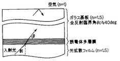
ここで、全反射光学部材の具体的な一構成例と、その構成例における光学部材の分光透過率をシミュレーションにより求めた結果を説明する。図25に全反射光学部材の一構成例を示した。この場合の全反射光学部材は、入射光の導入側から、光路を変化させる光学要素としての光拡散フィルム(屈折率n=1.5)、光路を選択する光学要素としての誘電体多層膜、ガラス基板(屈折率n=1.5)の順に積層されている。なお、ガラス基板の光路前方には、空気(屈折率n=1.0)が存在する。誘電体多層膜は、TiO2/SiO2/…/SiO2/TiO2なる29層構造の多層膜とし、各層の光学厚は1/4λ(ただし、波長λ=440[nm])に設定した。また、入射光は、図26に示す波長λ=350〜400[nm]のUV光源を用いた。そして、この場合の全反射臨界角θCは約40[deg]となる。
【0192】
上記条件の下で光学部材(誘電体多層膜)の分光透過率を求めたところ、図27、図28に示す結果を得た。図27は波長λに対する分光透過率Tの変化を入射角θ毎に示したグラフで、図28は入射角θに対する分光透過率Tを波長λ毎に示したグラフである。図27(a)に示すように、入射角θが0[deg]の場合は、UV光源の波長域における分光透過率Tが略0[%]となっており、光学部材から透過されることはない。また、図27(b)に示す入射角θが全反射臨界角θCの直前となる40[deg]の場合も光学部材から透過されることはない。図27(c)に示す入射角θが70[deg]の場合は、P波に対しては略100[%]の分光透過率で、S波に対しては略0[%]となり、P波とS波の平均は約50[%]となっている。
【0193】
また、図28(a)に示すように、UV光源の波長域における短波長側の波長λ=350[deg]の場合は、P波に対しては入射角θが約50[deg]以上から分光透過率が向上しており、図28(b)に示す中心波長λ=375[nm]の場合は、入射角θが約46[deg]以上から分光透過率が向上し、さらに、図28(c)に示す長波長側の波長λ=400[nm]の場合は、入射角θが約42[deg]以上から分光透過率が向上している。従って、P波を用いて光学部材で全反射させたり、光学部材の諸条件を変更してS波の分光特性をP波に近い特性に適宜設計することにより、UV光源の波長域の入射光を、その入射角θが全反射臨界角θC以下の角度では選択的に反射させ、且つ、全反射臨界角θCより大きい角度では透過させることができる。これにより、光学部材の誘電体多層膜を光路を選択する光学要素sとして実用上十分に機能させることができる。
【0194】
なお、前述では誘電体多層膜の例としてTiO2/SiO2からなる多層膜を挙げたが、対象とする光の波長に対して適宜その材料を選択することが好ましい。例えば、可視光、赤外線に対しては、・高い屈折率材料(屈折率が概ね1.8以上の材料)として、TiO2,CeO2,Ta2O5,ZrO2,Sb2O3,HfO2,La2O3,NdO3,Y2O3,ZnO,Nb2O5・比較的高い屈折率材料(屈折率が概ね1.6〜1.8の材料)として、MgO,Al2O3,CeF3,LaF3,NdF3・低い屈折率材料(屈折率が概ね1.5以下の材料)として、SiO2,AlF3,MgF2,Na3AlF6,NaF,LiF,CaF2,BaF2等が好ましい。
【0195】
紫外線に対しては、・高い屈折率材料(屈折率が概ね1.8以上の材料)として、ZrO2,HfO2,La2O3,NdO3,Y2O3又は、TiO2,Ta2O5,ZrO2(但し、光の波長が概ね360nm〜400nm)・比較的高い屈折率材料(屈折率が概ね1.6〜1.8の材料)として、MgO,Al2O3,LaF3,NdF3・低い屈折率材料(屈折率が概ね1.5以下の材料)として、SiO2,AlF3,MgF2,Na3AlF6,NaF,LiF,CaF2等が好ましい。
【0196】
【発明の効果】
本発明に係る表示素子によれば、光変調素子へ面状に導入した入射光の少なくとも一部が光変調素子の構成する層の界面で全反射する一方、入射光導入側の反対側からは入射光が実質的に出射しない特性を有する全反射光学部材と、この全反射光学部材の全反射面側に配設すると共に全反射面から入射光を選択的に結合させて取り出す光結合要素とを備えることにより、面状に導入された入射光が全反射光学部材に照射されたときに、入射光が全反射光学部材内に導入され、その導入された入射光の少なくとも一部が光変調素子の構成する層の界面で全反射する一方、入射光導入側の反対側からは入射光が実質的に出射されなくなる。この全反射光学部材の全反射面に入射光を結合させて取り出す光結合要素を選択的に近接配置することにより、近接配置された光結合要素に全反射光が取り出されて入射光光路前方に出射される。これにより、面状の入射光を面状のまま高効率で光変調素子に導入でき、光結合要素の近接配置状態に応じた選択的な光変調が行える。従って、導波路や導光板を用いた表示方式を用いることなく、エネルギ効率を高めた光変調が可能となる。
また、この光変調素子では、光変調素子内に入射光の光路を選択する光学要素が配置され、この光路を選択する光学要素へ面状に入射光を導入する。導入された面状の入射光は、光路を選択する光学要素によって入射光の光路が特定の方向或いは任意の方向に変化させられ、その実質的全てが光変調素子の構成する層の界面で全反射により反射される。このため、入射光の形状、導入位置、並びに光源の種類に制限を受けることなく、面状の入射光を面状のまま直接的に高効率で導入でき、所望の界面で面状の全反射光を高効率で得ることができる。また、入射角依存性がなく吸収のない反射体を構成することができ、光変調素子からの透過光が実質的に生じないため、光利用効率を高めることができる。
また、この光変調素子では、全反射光学部材を構成する層が入射光の波長域に対して実質的に吸収されないため、入射光及び全反射された入射光の損失を抑えて高効率化を図ることができる。
【0197】
本発明に係る表示素子は、上記光変調素子と平面光源とを備えることにより、平面光源から出射される入射光を光変調素子に導入することで、光変調素子の全反射光学部材に導入された光を光結合要素により光変調して光路前方へ選択的に出射することができる。これにより、高効率且つ高品位で所望の表示を行うことができる。
【0198】
本発明に係る露光素子は、上記表示素子を用い、予め設定された露光データに基づき光変調することで、露光対象に向けて選択的に光が出射され、露光対象に露光処理を施すことができる。
【図面の簡単な説明】
【図1】本発明に係る光変調素子の搭載された表示素子の概略的な構成を示す図である。
【図2】全反射光学部材の具体的な一構成例を示す図である。
【図3】透過型の回折格子を示す図であって、(a)は体積ホログラム、(b)はレリーフ型回折格子、(c)は屈折率変調型回折格子である。
【図4】光拡散板を示す図であって、(a)は多孔質体、(b)は異なる屈折率を有する物質が分布・分散した異種屈折率分布体・分散体、(c)は表面が凹凸に形成された光拡散体又は散乱体である。
【図5】光干渉フィルタの層構成を示す図である。
【図6】光路を変化させる光学要素、光路を選択する光学要素、透明媒質u、透明媒質v、全反射面の前方側の透明媒質wがこの順で配置された光学素子に対し、各界面における入射角と各媒質の平均屈折率の関係を示す図である。
【図7】光を選択する光学要素への入射光の入射角度を示す図である。
【図8】入射光の波長に対する、光路を選択する光学要素の分光透過率を入射角毎に示したグラフである。
【図9】光路を選択する光学要素内外の光路を示す図である。
【図10】屈折により光路を変更する光結合要素を示す図であって、(a)はレンズアレイ、(b)はプリズムアレイ、(c)は屈折率分布レンズ体である。
【図11】取り出した光を拡散又は散乱させる光結合要素を示す図であって、(a)は多孔質体、(b)は高屈折率微粒子等の異なる屈折率を有する物質の分散体又は分布体、(c)は表面に凹凸が形成された光拡散体又は光散乱体である。
【図12】可撓薄膜により形成した表示素子を2次元配列した平面表示素子の平面図である。
【図13】図12のC−C断面図で(a)は非駆動時、(b)は駆動時の状態を示す図である。
【図14】平面表示素子の表示側に蛍光体を配置した励起発光型平面表示素子の平面図である。
【図15】図14のD−D断面図で(a)は非駆動時、(b)は駆動時の状態を示す図である。
【図16】本発明の第4実施形態に係る励起発光型平面表示素子であって、蛍光体を可撓薄膜上に形成した励起発光型平面表示素子の一部を示す断面図である。
【図17】本発明の第5実施形態に係る光結合要素の概念的な構成と、光変調作用を説明する図である。
【図18】PLDCを用いた光結合要素の概念的な構成と、光変調作用を説明する図である。
【図19】光路を選択する光学要素を液晶膜により構成した例を示す図である。
【図20】光路を選択する光学要素による分光透過率を示す図である。
【図21】本発明の第6実施形態に係る全反射光学部材であって、プリズムを用いて形成した構成例を示す図である。
【図22】マイクロプリズムアレイと透明媒質とを接合した全反射光学部材の断面構成を示す図である。
【図23】マイクロプリズムアレイと透明媒質とを接合した構造体の光路前方に、マイクロプリズムアレイの光入射角に応じた角度に光路を変化させる光学要素を設けて構成した全反射光学部材の断面構成を示す図である。
【図24】全反射光学部材の他の構成例をそれぞれ示す図である。
【図25】全反射光学部材の具体的な一構成例を示す図である。
【図26】入射光の波長域を示すグラフである。
【図27】波長λに対する分光透過率Tの変化を入射角θ毎に示したグラフである。
【図28】入射角θに対する分光透過率Tを波長λ毎に示したグラフである。
【図29】従来の導光板方式の平面表示素子の一部断面図である。
【図30】従来の平面表示素子の構成を示す図である。
【図31】図30の平面表示素子の動作を説明する図である。
【符号の説明】
2,3 全反射光学部材
4 平面光源
5 UV光平面光源
6,7,8 光結合要素
10 光路を変化させる光学要素
12,13 光路を選択する光学要素
14 透明媒質
16 透明媒質(空気等)
20 異なる屈折率を有する物質
22,52,66,72 全反射面
26 透明電極
28 配向層
30 コレステリック液晶層
32 信号電極
34 走査電極
38 光拡散層
40 可撓薄膜
42a,42b,42c 蛍光体
44 透明基板
45 前面板
48 ブラックマトリクス
50 波長選択反射膜
54 液晶層
56 PLDC層
60 マイクロカプセル
64 マイクロプリズムアレイ
68 プリズム
70 透明媒質
100 表示素子
200 平面表示素子
300,400 励起発光型平面表示素子
θ0,θ1,θ2,θ3 入射角
θC 全反射臨界角
λ 波長[0001]
BACKGROUND OF THE INVENTION
The present invention introduces planar incident light and displays a planar shape for displaying a desired image.Display element and exposure elementAbout.
[0002]
[Prior art]
There is a light modulation element that processes and displays an image or patterned data by controlling the amplitude (intensity), phase, or traveling direction of incident light. The light modulation element changes the refractive index of a substance that transmits light by an external field applied to the substance, and finally transmits or reflects this substance through optical phenomena such as refraction, diffraction, absorption, and scattering. Control the intensity of light. As this light modulation element, for example, there is a liquid crystal light modulation element using the electro-optic effect of liquid crystal, and it is suitably used for a liquid crystal display device which is a thin flat display element. As self-luminous thin flat display elements, plasma display devices, FEDs (field emission displays) and the like are known. The liquid crystal light modulation element is suitably used for a liquid crystal display device which is a thin flat display element.
[0003]
As a typical example of a liquid crystal display device, a nematic liquid crystal oriented so as to be twisted by 90 ° in parallel with the substrate and between the substrates is inserted and sealed between the substrates on which a pair of conductive transparent films are formed. , And a structure in which these are sandwiched between orthogonal polarizing plates. The display using this liquid crystal display device utilizes the fact that by applying a voltage to the conductive transparent film, the major axis direction of the liquid crystal molecules is aligned perpendicular to the substrate, and the transmittance of light from the backlight changes. Done. An active matrix liquid crystal panel using TFTs (thin film transistors) is used to provide good moving image compatibility.
[0004]
The plasma display device has a plurality of regularly arranged orthogonal electrodes corresponding to discharge electrodes arranged between two glass plates filled with a rare gas such as neon, helium, xenon, etc. Is a unit pixel. The display by this plasma display device is based on image information, by selectively applying a voltage to the counter electrode that specifies each intersection point, causing the intersection point to discharge and emit light, and the generated ultraviolet light is excited to emit light. Done.
[0005]
The FED has a structure as a flat display tube in which a pair of panels are arranged to face each other with a minute interval and the periphery of these panels is sealed. A fluorescent film is provided on the inner surface of the panel on the display surface side, and a field emission cathode is arranged for each unit light emitting region on the rear panel. A typical field emission cathode has a conical-projection field emission type microcathode called a micro-sized emitter tip. The display by the FED is performed by exciting the phosphor by taking out electrons using an emitter tip and irradiating the electrons with acceleration.
[0006]
However, in the above-described conventional flat display element, first, in the liquid crystal display device, light from the backlight is transmitted through multiple layers of a polarizing plate, a transparent electrode, and a color filter. In addition, image quality deterioration due to the viewing angle dependency peculiar to liquid crystal, moving picture image quality deterioration due to low-speed response, and large area cost due to TFT are problems. Further, in the plasma display device, discharge barrier ribs are formed for each pixel. Therefore, it is difficult to obtain high luminance with high efficiency when the definition is high, and there is a disadvantage that the cost is high because the driving voltage is high. Further, in the FED, it is necessary to make the inside of the panel an ultra-high vacuum in order to stabilize the discharge with high efficiency, and the manufacturing cost becomes high like the plasma display device, and the field emission electrons are accelerated. There is a disadvantage that a high voltage is required to irradiate the phosphor.
[0007]
In order to solve these problems, a flat display element has recently been developed that displays an image by displacing a flexible thin film by an electromechanical operation and thereby modulating light from a light source. There are various types of electromechanical operations, such as those using the piezoelectric effect due to voltage application and those using electromagnetic force due to current application. Especially, those using electrostatic force are flexible thin films for light modulation. If the displacement amount is about 1 μm, high-speed driving of several μs or less is possible with low voltage and low power consumption. In addition, since it has hysteresis characteristics in the voltage dependence of displacement, passive matrix drive is possible with high contrast in a two-dimensional array configuration, and active elements such as TFTs are not required, and large area flat display elements are manufactured at low cost. it can. As this type of flat display element, for example, there is one based on the light guide plate method described in the following document.
・ Large-Area Micromechanical Display IDRC 1997, p230-p233 ・ U.S. Pat. No. 5,771,321 ・ Special Table 2000-505911
[0008]
FIG. 29 is a partial cross-sectional view of a light guide plate type
[0009]
Other flat display elements are described in the following documents. Waveguide Panel Display Using Electromechanical Spatial Modulators, 1998 SID International Symposium Digest of Technical Papers, p.1022-p.1025. As shown in FIG. The
[0010]
In the
[0011]
According to the
[0012]
[Problems to be solved by the invention]
However, in the above-described optical waveguide type
[0013]
At the time of image display, in the
[0014]
The present invention has been made in view of the above-described conventional problems, and without using a display method using a waveguide or a light guide plate, any backlight light source can be used, while preventing a decrease in contrast at a low cost, Energy efficiencyRaise,High-quality image displayDisplay elementAn object of the present invention is to provide an exposure element capable of performing exposure processing.
[0015]
[Means for Solving the Problems]
To achieve the above object, the present invention according to claim 1The display element isPlanar light modulatorDisplay element includingBecauseA light source for introducing planar incident light into the light modulation element;IntroductionWasAt least part of the incident light,The light modulation elementTheA total reflection optical member having a characteristic that the incident light is not substantially emitted from the side opposite to the incident light introduction side while being totally reflected at the interface of the constituent layers, and a total reflection surface side of the total reflection optical member. And an optical coupling element that selectively couples and extracts incident light from the total reflection surface, and the total reflection optical memberIsAn optical element for selecting an optical path is disposed in the total reflection optical member, and at least a part of the planar incident light introduced into the total reflection optical member isSaidIntroduced into the optical element that selects the optical path,Substantially all of the transmitted light emitted from the optical element that selects the optical path is the interface of the layer in front of the incident optical path of the optical element that selects the optical path or the interface in front of the incident optical path of the optical element that selects the optical path An optical interference filter that has an angle component larger than the total reflection critical angle in the above, and has the property that incident light of other angle components is reflected and is not transmitted, and the optical element that selects the optical path includes a dielectric multilayer film, Or a Bragg reflection filter containing either a cholesteric liquid crystal or a volume hologram,The layer constituting the total reflection optical member has substantially no absorption in the wavelength range of the incident light.
[0016]
thisDisplay elementThen, when the introduced incident light is irradiated onto the total reflection optical member and introduced into the total reflection optical member, at least a part of the introduced incident light is totally reflected at the interface of the layers constituting the light modulation element. On the other hand, incident light is not substantially emitted from the side opposite to the incident light introduction side. By selectively placing the optical coupling element that couples the incident light to the total reflection surface of the total reflection optical member and selectively takes it out, the total reflected light is extracted to the optical coupling element arranged in the vicinity and is placed in front of the incident light optical path. Emitted. Thereby, planar incident light can be introduced into the light modulation element with high efficiency, and selective light modulation according to the close arrangement state of the optical coupling elements can be performed.
Also thisDisplay elementThen, an optical element for selecting an optical path of incident light is arranged in the light modulation element, and the incident light is introduced into the optical element for selecting the optical path in a planar shape. The introduced planar incident light is changed in the optical path of the incident light in a specific direction or an arbitrary direction by an optical element that selects the optical path, and substantially all of the incident light is entirely at the interface of the layers constituting the light modulation element. Reflected by reflection. Therefore, it is possible to introduce planar incident light directly and with high efficiency without being limited by the shape of the incident light, the introduction position, and the type of the light source, and the total reflection at the desired interface. Light can be obtained with high efficiency. In addition, a reflector having no incident angle dependency and no absorption can be formed, and light transmitted from the light modulation element is not substantially generated, so that the light utilization efficiency can be increased.
In addition, in this display element, an arbitrary wavelength selective reflection film can be formed with a large area and a simple configuration by using an optical interference filter including a dielectric multilayer film, and the incident angle dependence of the reflection wavelength is utilized. An optical element that easily selects an optical path can be formed. Further, by using a Bragg reflection filter including a cholesteric liquid crystal and a volume hologram, an optical element for selecting an optical path can be formed at low cost.
[0017]
The display element according to
[0018]
thisDisplay elementThen, when the introduced incident light is irradiated onto the total reflection optical member and introduced into the total reflection optical member, at least a part of the introduced incident light is totally reflected at the interface of the layers constituting the light modulation element. On the other hand, incident light is not substantially emitted from the side opposite to the incident light introduction side. By selectively placing the optical coupling element that couples the incident light to the total reflection surface of the total reflection optical member and selectively takes it out, the total reflected light is extracted to the optical coupling element arranged in the vicinity and is placed in front of the incident light optical path. Emitted. Thereby, planar incident light can be introduced into the light modulation element with high efficiency, and selective light modulation according to the close arrangement state of the optical coupling elements can be performed.
Also thisDisplay elementThen, from the incident light introduction side in the thickness direction of the light modulation element, the optical element that changes the optical path and the optical element that selects the optical path are arranged in this order, and the incident light is planarly applied to the optical element that changes the optical path. Is introduced. In the introduced incident light, the optical path of the incident light is changed in a specific direction or an arbitrary direction by the optical element that changes the optical path, and only the incident light in the specific direction is transmitted by the optical element that selects the optical path. Thereby, substantially all of the light introduced into the light modulation element is reflected by total reflection at the interface of the layers constituting the light modulation element. Therefore, it is possible to introduce planar incident light directly and with high efficiency without being limited by the shape of the incident light, the introduction position, and the type of the light source, and the total reflection at the desired interface. Light can be obtained with high efficiency. In addition, a reflector having no incident angle dependency and no absorption can be formed, and light transmitted from the light modulation element is not substantially generated, so that the light utilization efficiency can be increased.
In addition, in this display element, an arbitrary wavelength selective reflection film can be formed with a large area and a simple configuration by using an optical interference filter including a dielectric multilayer film, and the incident angle dependence of the reflection wavelength is utilized. An optical element that easily selects an optical path can be formed. Further, by using a Bragg reflection filter including a cholesteric liquid crystal and a volume hologram, an optical element for selecting an optical path can be formed at low cost.
[0019]
Claim3DescribedDisplay elementIs characterized in that the light coupling element takes out incident light by changing a condition of total reflection of incident light on the total reflection surface.
[0020]
thisDisplay elementThen, by arranging the optical coupling element close to the total reflection surface of the total reflection optical member, the total reflection condition on the total reflection surface changes, and the incident light introduced into the total reflection optical member becomes the optical coupling element. Coupled and removed.
[0021]
Claim4DescribedDisplay elementThe optical coupling element is formed of a flexible thin film supported by an electromechanical operation so as to be close to the total reflection surface of the total reflection optical member.
[0022]
thisDisplay elementThen, the optical coupling element is made to be a total reflection surface of a total reflection optical member by various methods such as a method using electrostatic force by applying voltage, a method using piezoelectric effect by applying voltage, and a method using electromagnetic force by applying current. By adopting a configuration close to the optical switch, it is possible to realize an optical switch that is power-saving and excellent in responsiveness.
[0023]
Claim5DescribedDisplay elementIs characterized in that the electromechanical operation is an operation using an electrostatic force as a drive source.
[0024]
thisDisplay elementThen, by driving the optical coupling element by electrostatic force, the flexible thin film is brought close to the total reflection surface of the total reflection optical member at a distance of several μm or less, so that low voltage and low power consumption can be achieved. High-speed driving is possible.
[0025]
Claim6DescribedDisplay elementIs characterized in that the optical coupling element is composed of a layer containing a liquid crystal whose optical properties are changed by application of an electric field.
[0026]
thisDisplay elementThen, the optical switching operation can be obtained with an inexpensive configuration by changing the optical characteristics of the liquid crystal by applying an electric field to the optical coupling element and changing the total reflection conditions.
[0027]
Claim7DescribedDisplay elementThe optical coupling elements are arranged in a one-dimensional array on the total reflection optical member.
[0028]
thisDisplay elementThen, by arranging the optical coupling elements in a one-dimensional array on the total reflection optical member, a light modulation element capable of one-dimensional simultaneous modulation can be formed.
[0029]
Claim8DescribedDisplay elementThe optical coupling elements are arranged in a two-dimensional array on the total reflection optical member.
[0030]
thisDisplay elementThen, by arranging the optical coupling elements in a two-dimensional array on the total reflection optical member, it is possible to form a light modulation element capable of two-dimensional simultaneous modulation and display an image.
[0031]
Claim9DescribedDisplay elementThe optical coupling element is connected to passive matrix driving means.
[0032]
thisDisplay elementIn particular, the optical coupling element uses an electrostatic force. For example, an electrode provided on the total reflection surface side of the total reflection optical member and an electrode provided on a flexible thin film partially supported. When a voltage is applied between them, the flexible thin film is displaced toward the total reflection surface side of the total reflection optical member. At this time, the shape of the flexible thin film and the mechanical properties such as the elastic constant, the flexible thin film and the total reflection are obtained. Hysteresis occurs in the displacement characteristics with respect to the applied voltage by appropriately selecting the gap distance from the surface. Using this hysteresis characteristic, for example, a plurality of stripe electrodes are arranged on the total reflection surface side of the total reflection optical member as signal electrodes, and a plurality of stripe electrodes perpendicular to the electrodes are formed on the flexible thin film. By arranging scanning electrodes in parallel and applying potentials appropriately to these signal electrodes and scanning electrodes, the transmittance of any two-dimensionally arranged pixel can be controlled with high contrast without using active elements such as TFTs. It becomes possible. In other words, so-called passive matrix driving is possible, thereby realizing an inexpensive and large-area light modulation element.
[0033]
Claim10DescribedDisplay elementIs characterized in that the optical coupling element has optical path changing means for changing the optical path of the extracted light.
[0034]
thisDisplay elementThen, by changing the optical path of the light extracted by the optical coupling element, it becomes possible to condense or diffuse the emitted light from the optical element in a specific direction.
[0035]
Claim11DescribedDisplay elementIs characterized in that the optical path changing means changes the optical path of the extracted light by refraction.
[0036]
thisDisplay elementThen, by changing the optical path of the light extracted from the optical coupling element by refraction, the optical path can be changed while maintaining the light quantity.
[0037]
Claim12DescribedDisplay elementIs characterized in that the optical path changing means comprises any one of a lens array, a prism array, and a gradient index lens body.
[0038]
thisDisplay elementThen, by appropriately selecting an optical element including a lens array, a prism array, and a gradient index lens body suitable for mass production, good performance can be exhibited while achieving cost reduction.
[0039]
Claim13DescribedDisplay elementIs characterized in that the optical path changing means changes the optical path of the extracted light by diffraction.
[0040]
thisDisplay elementThen, by changing the optical path of the light extracted from the optical coupling element by diffraction, the optical path of the light can be set with high accuracy.
[0041]
Claim14DescribedDisplay elementIs characterized in that the optical path changing means comprises any one of a volume hologram, a phase modulation diffraction grating, and an amplitude modulation diffraction grating.
[0042]
thisDisplay elementThen, for example, mass transfer production is possible by a photopolymer method or an injection molding method, and the cost of the optical element itself can be reduced.
[0043]
Claim15DescribedDisplay elementIs characterized in that the optical path changing means changes the optical path of the extracted light by light diffusion or light scattering.
[0044]
thisDisplay elementThen, the extracted light can be emitted in an arbitrary direction by changing the optical path by light diffusion or light scattering.
[0045]
Claim16DescribedDisplay elementIs characterized in that the optical path changing means is any one of a porous body, a dissimilar refractive index dispersion or distribution body, a light diffusing body having an uneven surface, or a light scattering body.
[0046]
thisDisplay elementThen, the cost of the optical element itself can be reduced by appropriately selecting a porous body, a different refractive index dispersion or distribution body, a light diffusion body or a light scattering body suitable for mass production.
[0047]
Claim17DescribedDisplay elementIs characterized in that the optical coupling element has specific wavelength component absorbing means for absorbing and emitting the specific wavelength component of the extracted light.
[0048]
thisDisplay elementThen, by absorbing and emitting a specific wavelength component among the wavelength components of the extracted light, a plurality of colors of emitted light can be selectively obtained even with the same type of incident light.
[0049]
Claim18DescribedDisplay elementIs characterized in that the optical coupling element has a phosphor that emits light upon receiving the extracted light.
[0050]
thisDisplay elementThen, by having a phosphor that emits and emits light by the extracted light, a plurality of colors of emitted light can be selectively obtained by color development of the phosphor.
[0051]
Claim19DescribedDisplay elementIs characterized by having a phosphor that emits and emits light upon receiving the outgoing light extracted by the optical coupling element.
[0052]
thisDisplay elementThen, for example, a phosphor may be disposed in front of the optical path of the optical coupling element, and the emitted light extracted from the optical coupling element can be converted into an arbitrary wavelength.
[0053]
Claim20DescribedDisplay elementThe optical element that changes the optical path and the optical element that selects the optical path are in optical contact with each other.
[0054]
thisDisplay elementThen, since the optical element that changes the optical path and the optical element that selects the optical path are in optical contact with each other, both light coupling properties can be improved and the optical element that changes the optical path is directional. , The incident light can be introduced from the optical element that changes the optical path into the optical element that selects the optical path while maintaining the incident angle component.
[0055]
Claim21DescribedDisplay elementThe optical element that changes the optical path and the optical element that selects the optical path are in optical contact with each other through a medium having a refractive index greater than 1.
[0056]
thisDisplay elementThen, the optical element that changes the optical path and the optical element that selects the optical path are in optical contact with each other through a medium having a refractive index larger than 1, so that total reflection does not occur at the interface with the medium. Incident light can be introduced from an optical element that changes the optical path into an optical element that selects the optical path.
[0057]
Claim22DescribedDisplay elementComprises a transparent medium constituting a part of the total reflection optical member, and an optical element for changing the optical path is arranged in front of the optical path of the transparent medium.
[0058]
thisDisplay elementThen, after incident light is transmitted through the transparent medium, it is introduced into an optical element that changes the optical path, and only incident light in a specific direction is transmitted.
[0059]
Claim23DescribedDisplay elementComprises a transparent medium constituting a part of the total reflection optical member, and an optical element for selecting the optical path is arranged in front of the optical path of the transparent medium.
[0060]
thisDisplay elementThen, after the incident light passes through the transparent medium, it is introduced into the optical element that selects the optical path, and only the incident light in a specific direction is transmitted.
[0061]
Claim24DescribedDisplay elementComprises a transparent medium constituting a part of the total reflection optical member, and an optical element for changing the optical path and an optical element for selecting the optical path are arranged in this order in front of the optical path of the transparent medium. .
[0062]
thisDisplay elementThen, the incident light is introduced into the optical element that changes the optical path after passing through the transparent medium, the optical path of the incident light is changed in a specific direction or an arbitrary direction, and further introduced into the optical element that selects the optical path, Only incident light in a specific direction is transmitted.
[0063]
Claim25DescribedDisplay elementThe optical element that changes the optical path has an average refractive index nt of the optical element that changes the optical path, nw the refractive index of the medium on the front side of the total reflection interface in front of the optical path, and the optical element that changes the optical path. When the angle of the light traveling through is θt, the light is output forward including at least the light of the angle θt that satisfies the condition of sin θt> nw / nt.
[0064]
thisLight modulation elementThen, at least the light of the angle θt that satisfies the condition of sin θt> nw / nt passes through the optical element that changes the optical path, and is output forward while changing the optical path.
[0065]
Claim26DescribedDisplay elementIs characterized in that the optical element that changes the optical path changes the optical path by refraction.
[0066]
thisDisplay elementThen, the optical element that changes the optical path can be introduced into the light modulation element without substantially reducing the intensity of the incident light by changing the optical path of the incident light by refraction.
[0067]
Claim27DescribedDisplay elementThe optical element that changes the optical path is any one of a lens array, a prism array, and a different kind of refractive index distribution body in which different refractive indexes are distributed.
[0068]
thisDisplay elementThen, by appropriately selecting an optical element using a lens array, a prism array, or a different refractive index distribution body suitable for mass production, good performance can be exhibited while reducing costs.
[0069]
Claim28DescribedDisplay elementIs characterized in that the optical element that changes the optical path changes the optical path by diffraction.
[0070]
thisDisplay elementThen, the optical element that changes the optical path changes the optical path of the incident light by, for example, diffraction by a transmission diffraction grating, so that the incident light can be introduced into the light modulation element with a high-precision incident angle.
[0071]
Claim29DescribedDisplay elementThe optical element that changes the optical path is any one of a volume hologram, a phase modulation type diffraction grating, and an amplitude modulation type diffraction grating.
[0072]
thisDisplay elementThen, for example, mass transfer production is possible by a photopolymer method or an injection molding method, and the cost of the light modulation element itself can be reduced.
[0073]
Claim30DescribedDisplay elementIs characterized in that the optical element for changing the optical path changes the optical path by light diffusion.
[0074]
thisDisplay elementThen, the optical element that changes the optical path can change the optical path by light diffusion, so that incident light can enter the light modulation element from an arbitrary direction.
[0075]
Claim31DescribedDisplay elementIs characterized in that the optical element for changing the optical path is any one of a porous body, a different refractive index distribution body or a dispersion, a diffuser having a concavo-convex surface, or a scatterer.
[0076]
thisDisplay elementThen, by appropriately selecting an optical element using a porous body, a different refractive index distribution body or dispersion body, and a diffusing body suitable for mass production, good performance can be exhibited while reducing costs.
[0077]
Claim32DescribedDisplay elementIs characterized in that the optical element that changes the optical path changes the optical path by light reflection.
[0078]
thisDisplay elementThen, the optical element that changes the optical path changes the optical path by light reflection, so that incident light can enter the light modulation element from an arbitrary direction.
[0079]
Claim33DescribedDisplay elementThe optical element that selects the optical path has an average refractive index ns of the optical element that selects the optical path, nw the refractive index of the medium on the front side of the total reflection interface in front of the optical path, and the optical element in the medium of the optical element that selects the optical path. When the angle of the light traveling through is θs, substantially all of the light of the angle θs that satisfies the condition of sin θs> nw / ns is transmitted.
[0080]
thisDisplay elementThen, the light of the angle θs that satisfies the condition of sin θs> nw / ns transmits substantially all of the optical element that selects the optical path, and other light is reflected, whereby only a specific light component is selectively transmitted. The
[0081]
Claim34DescribedDisplay elementThe optical element that selects the optical path has a function of selectively reflecting the wavelength range of incident light, and the incident angle of the incident light to the optical element that selects the optical path is on the surface of the optical element. In contrast, as the angle becomes shallower, the wavelength of incident light selectively reflected is shifted to the short wavelength side.
[0082]
thisDisplay elementThen, the optical element that selects the optical path has a function of selectively reflecting the wavelength range of incident light, and the incident angle of the incident light on this optical element is a shallow angle with respect to the surface of the optical element. Accordingly, the wavelength of incident light that is selectively reflected shifts to the short wavelength side. By utilizing this property, an optical element that selects an optical path so that only incident light with a predetermined incident angle component is transmitted is designed to selectively extract only incident light with an incident angle component that causes total reflection. It can be made possible.
[0083]
Claim35DescribedDisplay elementWhen the incident angle of the incident light to the optical element that selects the optical path is less than or equal to the total reflection critical angle before the incident light optical path, the optical element that selects the optical path It is characterized in that substantially all of the incident light is selectively reflected.
[0084]
thisDisplay elementThen, the incident angle of the incident light to the optical element that selects the optical path varies depending on the incident angle and the refractive condition of each layer, and the incident angle to the total reflection interface in front of the incident optical path is the total reflection critical angle at the total reflection interface. In the following, the optical element that selects the optical path selectively reflects substantially all of the incident light. Thereby, incident light having an angle component that is not totally reflected at the total reflection interface is selectively reflected and is not transmitted forward of the optical path.
[0085]
Claim36DescribedDisplay elementIs characterized in that substantially all of the totally reflected incident light returns to the incident light introduction side of the total reflection optical member.
[0086]
thisDisplay elementThen, substantially all of the totally reflected incident light returns to the incident light introduction side of the light modulation element, so that light guide, accumulation, confinement, etc. are performed in the medium having the total reflection surface. Absent.
[0087]
Claim37DescribedDisplay elementIs characterized in that the incident light is diffused light having an arbitrary incident angle.
[0088]
thisDisplay elementThen, since the incident light is diffused light having an arbitrary incident angle, incident light from various directions can be introduced into the light modulation element, and the uniformity of the incident light can be improved.
[0089]
Claim38The display element described includes a phosphor in front of the optical coupling element or its optical path, and reflects a light emission wavelength component of the phosphor between the total reflection surface of the total reflection optical member and the optical coupling element. In addition, an optical filter that transmits the wavelength component of the incident light is interposed.
[0090]
In this display element, the phosphor emits light when incident light passes through the optical filter and irradiates the phosphor. Of the light emitted from the phosphor, light emitted toward the rear of the optical path is reflected and emitted by the optical filter to the front of the optical path. As a result, light utilization efficiency is improved, and display with higher luminance is possible.
[0091]
Claim39The display element described is in front of the optical coupling element or its optical path.PhosphorAnd an optical filter that transmits the emission wavelength component of the phosphor and shields the wavelength component of the incident light is provided in front of the optical path of the phosphor.
[0092]
In this display element, for example, when UV light is used as incident light, the transmitted light (leakage light) can be prevented from being emitted to the display side (observer side).
[0093]
Claim40The display element described is in front of the optical coupling element or its optical path.PhosphorIn front of the optical path of the phosphorOf the phosphorAn optical filter that absorbs light in the emission wavelength region is provided.
[0094]
In this display element, for example, when the emission wavelength of the phosphor is in the visible light range, an ND filter (transmittance of about 20 to 70%) that absorbs visible light is provided on the display side (observer side). Even if it exists, display can be performed with high contrast.
[0095]
Claim41The display element described is characterized in that the optical filter is an optical interference filter including a dielectric multilayer film.
[0096]
In this display element, by using an optical interference filter including a dielectric multilayer film, an arbitrary wavelength selective reflection film can be formed with a large area and a simple configuration, and it is easy to make use of the incident angle dependence of the reflection wavelength. An optical filter can be formed.
[0097]
Claim42The display element described is characterized in that the optical filter is a Bragg reflection filter including a cholesteric film.
[0098]
In this display element, an optical filter can be formed at low cost by using a Bragg reflection filter including cholesteric liquid crystal.
[0099]
Claim43The display element described is characterized in that the main wavelength of the incident light is 350 nm to 400 nm.
[0100]
In this display element, by setting the main wavelength of incident light to 350 nm to 400 nm, it is possible to increase the light emission luminance of the phosphor and display an image with higher luminance.
[0101]
Claim44The display element described is characterized in that a main wavelength of the incident light is 400 nm to 500 nm.
[0102]
In this display element, by setting the main wavelength of incident light to 400 nm to 500 nm, the display element can be configured using an organic material that is not resistant to UV light.
[0103]
Claim45The display element described is characterized in that the phosphor emits visible light.
[0104]
In this display element, when the phosphor emits visible light, visible light can be displayed from a UV light source.
[0105]
Claim46The display element described is characterized in that the phosphor forms a light emitter that emits red, green, and blue light.
[0106]
In this display element, the formed red, green, and blue phosphors emit light so that a full color image can be displayed.
[0107]
Claim47In the display element described above, the planar light source is a light source provided inside the total reflection optical member, and the incident light is light emitted from the light source.
[0108]
In this display element, by providing the light source inside the total reflection optical member, the light emitted from the light source is directly introduced into the light modulation element, and the loss at the time of introducing incident light is greatly reduced.
[0109]
Claim48The display element described is characterized in that the incident light is incident from the outside of the total reflection optical member.
[0110]
In this display element, by introducing incident light from the outside of the total reflection optical member, the design freedom of the display element is improved, and even a large light source can be used, and high output can be easily performed. .
[0111]
Claim49The display element described includes a reflector that is provided opposite to the incident light introduction side of the display element and re-injects incident light reflected by the display element after being introduced into the display element to the display element side. It is characterized by that.
[0112]
In this display element, by providing a reflector facing the incident light introduction side of the display element, the incident light once incident on the display element and reflected by the display element is irradiated to the reflector, and further from the reflector. Since the reflected light is re-entered to the display element side, the light is recycled, the light utilization efficiency is improved, and the efficiency is increased.
[0113]
Claim50The exposure device described
[0114]
In this exposure element,Claims 1 to 49By using the display element according to any one of the above and performing light modulation based on preset exposure data, light is selectively emitted toward the exposure target, and the exposure process can be performed.
[0115]
DETAILED DESCRIPTION OF THE INVENTION
Hereinafter, according to the present inventionDisplay element and exposure elementA preferred embodiment of the present invention will be described in detail with reference to the drawings. FIG. 1 shows a conceptual configuration of a display element on which a light modulation element according to the present invention is mounted. The
[0116]
The
[0117]
Hereinafter, each component of the
[0118]
The
[0119]
When light diffusion is used, the light diffusing plate shown in FIG. 4 is used, a porous body (see FIG. 4A), and a heterogeneous refractive index distribution body in which
[0120]
The
θC= Sin-1(N2 / n1) (1)
[0121]
As one configuration example of the
[0122]
Here, the optical properties of the
[0123]
nv · sin θv = nw
nu · sin θu = nv · sin θv = nw
ns · sin θs = nu · sin θu = nw
nt · sin θt = ns · sin θs = nw (2)
Here, θt, θs, θu, and θv are optical path angles in the respective media.
[0124]
Therefore, as a condition of the
[0125]
On the other hand, the condition of the
[0126]
Next, the planar
[0127]
As the incident light, light in a wavelength band of a specific band such as UV light, visible light such as blue light and green light, and infrared light can be used. In addition, as a type of light source, for example, a fluorescent lamp, which is an electron tube filled with an inert gas or mercury vapor, a mercury lamp, a neon tube lamp, a crux tube, etc., which is generally used and can be used as it is, collimated light Laser light sources that can be easily obtained, inexpensive and wavelength-determined LEDs, inorganic or organic EL that can obtain planar light, and by emitting white light and filtering according to the purpose, any wavelength component can be extracted An incandescent lamp, a cathode ray display tube such as a CRT, and a cathode ray lamp that directly obtains planar light to be introduced into the display element, or an FED that is also a flat display tube and directly obtains planar light. Etc. can be used.
[0128]
The planar light source other than the one that directly obtains planar light, for example, forms planar light by concentrating a plurality of point light sources or line light sources, or deflects and scans one or a plurality of light beams. Thus, planar light is formed. Alternatively, light from a point light source or a line light source may be irradiated by forming planar light by passing through a filter that performs diffusion / scattering, refraction, diffraction, or the like. As a method of concentrating a plurality of point light sources and line light sources, for example, a configuration in which LEDs are arranged in a matrix in a vertical and horizontal direction and light is emitted so that the amount of light is uniform, or a configuration in which fluorescent tubes are arranged in parallel to emit light is used. Can be mentioned. Also, as a deflection scanning method, for example, a laser beam such as a semiconductor laser or a gas laser is deflected and scanned by a polygon mirror or the like, or planar light is obtained by scanning the cathode line by vacuum sealing the entire flat display element. For example, a phosphor that excites the phosphor to emit light. Note that planar light can be obtained more efficiently by using a multi-beam that forms a plurality of irradiation spots. In any case, any light source such as a point light source or a line light source can be used as long as planar light equivalent to a planar light source can be obtained.
[0129]
Further, when the total reflection
[0130]
Next, the characteristics of the
[0131]
First, as shown in FIG. 7, incident light is incident on the
[0132]
As described above, the total reflection critical angle θ on the
[0133]
The optical path A has an incident angle θ of incident light.iIs the total reflection critical angle θ at the total reflection surface 22.CIn the following cases, the
[0134]
On the other hand, FIG. 9B shows that the refractive index na on the incident light side is different from the refractive index nb of the
[0135]
By configuring the total reflection
[0136]
Therefore, only the light that is totally reflected by the
[0137]
Further, a part of the light reflected on the incident light introduction side on the surface of the
[0138]
Next, the
(1) What changes the optical path by refraction or has the function The output light taken out by placing it close to the total reflection surface 22 changes its optical path by refraction. For example, FIG. ), A prism array shown in FIG. 10B, a gradient index lens body shown in FIG. 10C, and the like. According to these lens arrays and prism arrays, the output light extracted from the
[0139]
(2) Transmission type diffraction grating or one having its function As a transmission type diffraction grating that transmits extracted light and changes the emission direction by diffraction, a volume hologram shown in FIG. Examples include a relief type diffraction grating shown in FIG. 3B, a refractive index modulation type diffraction grating shown in FIG. 3C, and an amplitude modulation type diffraction grating. According to these transmission type diffraction gratings, the emission angle of output light can be set accurately. Further, for example, mass production is possible by a photopolymer method or an injection molding method, and the cost of the display element itself can be reduced.
(3) Light diffuser or light scatterer or one having a function thereof As a light diffuser or light scatterer for diffusing or scattering extracted light, a porous material suitable for mass production shown in FIG. A dispersion or distribution of the
[0140]
(4) What absorbs incident light or what has its function Absorbs incident light, for example, a transmissive image film on which image data is recorded. By outputting the output light extracted from the
[0141]
Here, the light modulation operation of the
[0142]
According to the
[0143]
Since a part of the incident light reflected at each interface in the
[0144]
Next, a second embodiment of the present invention configured by two-dimensionally arranging the display elements described above will be described with reference to FIGS. 12 is a plan view of a flat display element in which display elements formed of a flexible thin film are two-dimensionally arranged. FIG. 13 is a cross-sectional view taken along the line CC of FIG. 12, where (a) is non-driven and (b) is driven. It is a figure which shows the state of time. As shown in FIGS. 12 and 13, in the
[0145]
The light diffusing layer having electrical insulation is, for example, SiO.2, SiNxAn inorganic insulating film such as polyimide or an organic insulating film such as polyimide can be used. In order to form a gap between the flexible thin film and the signal electrode, a sacrificial layer is previously formed in the gap, and after forming the flexible thin film on the gap, the sacrificial layer is finally etched away to obtain a gap. Can do. As a means for imparting light diffusibility to the flexible thin film, it can be obtained by a method of forming irregularities on the surface by photolithography, etching or the like, a method of dispersing fine particles having different refractive indexes in the insulating film, or the like.
[0146]
The light modulation operation of the
[0147]
On the other hand, as shown in FIG. 13B, when a drive voltage Von is applied between the
[0148]
As described above, according to the
[0149]
Next, a description will be given of a third embodiment of the present invention in which display is performed by optically modulating ultraviolet rays by the display element of the present invention to excite and emit phosphors. FIG. 14 is a plan view of an excitation light emission type flat display element in which a phosphor is arranged on the display side of the above flat display element, and FIG. 15 is a sectional view taken along the line DD in FIG. (B) is a figure which shows the state at the time of a drive. As shown in FIGS. 14 and 15, the excitation light emission type
[0150]
The
[0151]
The
[0152]
Next, the light modulation operation of the excitation light emission type
[0153]
On the other hand, as shown in FIG. 15B, when the drive voltage Von is applied between the
[0154]
Thus, according to the excitation light emission type
[0155]
In addition, the two-dimensionally arranged light modulation elements having the above-described configuration can be applied to the applied voltage by appropriately selecting the shape of the flexible thin film and the mechanical properties such as the elastic constant and the gap distance between the flexible thin film and the total reflection surface. There is hysteresis in the displacement characteristics for. Utilizing this hysteresis characteristic, by appropriately applying a potential to the
[0156]
In this way, an inexpensive and large-area flat display element can be realized by connecting the light modulation element to a commonly used passive matrix driving means and applying a potential to the
[0157]
Next, a description will be given of a fourth embodiment of the present invention in which display is performed by optically modulating ultraviolet rays by the display element of the present invention and exciting and emitting phosphors. FIG. 16 is a cross-sectional view showing a part of the excitation light emission type flat display element of this embodiment in which the phosphor of the above-described excitation light emission type flat display element is formed on a flexible thin film. (B) is a figure which shows the state at the time of a drive. As shown in FIG. 16A, the excitation light emission type
[0158]
In the third and fourth embodiments, UV light is used as incident light, and full color display is performed using G (green) and R (red) phosphors excited and emitted by the transmitted light. However, in addition to this, blue (the main wavelength range is 400 to 500 nm) as incident light, and G (green) and R (red) phosphors that are excited and emitted by this blue light may be used. The combination is not limited to the above example. By using visible light such as blue as incident light, an organic material that is not resistant to UV light can be used as a material constituting the element of the present invention.
[0159]
Further, a fluorescent material may be provided in front of the flexible thin film or its optical path, and an optical filter that transmits the emission wavelength component of the fluorescent material and shields the wavelength component of incident light may be provided further in front of the optical path. According to this configuration, for example, when UV light is used as incident light, the transmitted light (leakage light) can be prevented from being emitted to the display side (observer side). Furthermore, instead of the optical filter, an optical filter that transmits the emission wavelength component of the phosphor and shields the wavelength component of the incident light may be provided. According to this configuration, for example, when the emission wavelength of the phosphor is in the visible light range, an ND filter (transmittance of about 20 to 70%) that absorbs visible light is provided on the display side (observer side), thereby providing a bright place. Even so, display can be performed with high contrast.
[0160]
Next, a description will be given of a fifth embodiment of the present invention in which the optical coupling element of the display element described above is formed of liquid crystal and electro-optic light modulation is performed. FIG. 17 shows a conceptual configuration of the optical coupling element of this embodiment and a diagram for explaining the light modulation action. In the optical coupling element 7 of the present embodiment, the
[0161]
FIG. 17A shows a state in which the non-driving voltage Voff is applied to each electrode, and FIG. 17B shows a state in which the driving voltage Von is applied to each electrode. In the state where the non-driving voltage Voff is applied, the refractive index of the
[0162]
Thus, according to the optical coupling element having the above-described configuration, light modulation can be performed by driving voltage control that modulates the refractive index of the
[0163]
Further, as a modification of the present embodiment, a display element can be configured using PLDC (polymer dispersion type liquid crystal) instead of the above-mentioned liquid crystal layer as an optical coupling element. FIG. 18 shows a conceptual configuration of an optical coupling element using PLDC and a diagram for explaining an optical modulation action. In the
[0164]
Next, other embodiments of the total reflection optical member used in the display element, flat display element, and excitation light emission type flat display element described above will be described below. First, a fifth embodiment of the present invention in which a Bragg reflection filter is used as an optical element for selecting an optical path instead of the above-described optical interference filter will be described. FIG. 19 shows an example in which the
[0165]
The filtering effect of the cholesteric
[0166]
Δn = ne−no (3)
The average refractive index n can be approximately expressed by the equation (4).
n = (ne + no) / 2 (4)
[0167]
Further, when the spiral pitch of the cholesteric
λ (θ) = λ (0) · cos [sin-1(Sinθ / n)] (5)
[0168]
However, incident light is assumed to be incident from air (refractive index = 1). Here, λ (0) [nm] has an incident angle of θ0That is, it is the center wavelength when perpendicularly incident on the layer, and can be expressed by equation (6).
λ (0) = n · P (6)
Further, the reflection wavelength width Δλ [nm] can be expressed by equation (7).
Δλ = Δn · P (7)
[0169]
Therefore, by forming the layer by controlling the ordinary light refractive index no, the extraordinary light refractive index ne, and the helical pitch P, which are physical properties of the cholesteric
[0170]
The cholesteric
[0171]
It is also possible to form a film using a polymer cholesteric liquid crystal. In this case, as described above, a polymer cholesteric liquid crystal and a photopolymerization initiator are coated on a polyimide alignment film with an adjustment solution mixed with an organic solvent, and then aligned at an appropriate temperature, and ultraviolet rays are exposed to necessary portions. And photopolymerized. The reflection incident angle can be controlled by appropriately selecting the alignment temperature, and is stabilized by photopolymerization.
[0172]
Here, the spectral transmittance of the
[0173]
According to this configuration, it is possible to realize the
[0174]
When the spiral structure of the cholesteric
[0175]
A volume hologram is effective as an optical element having the function of Bragg reflection other than the cholesteric liquid crystal. The volume hologram has a Bragg reflection function due to a grating-like refractive index distribution formed in the film, and reflects a specific wavelength. Further, when the incident angle increases, the reflected wavelength shifts to the short wavelength side and functions as an optical path selection film. The volume hologram can be formed by using a photographic material for hologram, a phase-separated photopolymer, HPDLC (holographic polymer dispersed liquid crystal), a photolithography material or the like as a photosensitive material, and subjecting it to multibeam interference exposure.
[0176]
Next, a sixth embodiment of the present invention in which the total reflection optical member is formed with a simpler and less expensive configuration without using the above-described optical interference filter and Bragg reflection filter will be described. In the present embodiment, the total reflection optical member is formed using a prism. A configuration example of the total reflection optical member in this case is shown in FIG. The total reflection
[0177]
As the material of the
[0178]
As a manufacturing method of the
[0179]
As a photolithography method, ultraviolet light (or visible light) is exposed through a light-shielding mask appropriately patterned on a photodissolving resin or a photocurable resin, and dissolution development is performed on an exposed portion or unexposed portion, respectively. It is formed by. It is possible to obtain a microprism having a desired shape by the resin material and the exposure dose distribution. In addition, depending on the resin material, it is possible to obtain a
[0180]
According to the total reflection
[0181]
The
[0182]
Furthermore, an optical element that changes the optical path to an angle corresponding to the light incident angle of the
[0183]
According to this configuration, when planar incident light that is collimated light is applied to the total reflection
[0184]
Here, another configuration example of the total reflection
[0185]
Next, in the total reflection optical member shown in FIG. 24B, the
[0186]
Furthermore, the total reflection optical member shown in FIG. 24C has a configuration in which a transparent medium 24 having a refractive index lower than the refractive index of the
[0187]
Next, the total reflection optical member shown in FIG. 24D is a structure in which an
[0188]
Next, the total reflection optical member shown in FIG. 24E includes an
[0189]
Next, the total reflection optical member shown in FIG. 24F is a structure in which a
[0190]
Even the total reflection optical member having each configuration described above can be applied to the total reflection optical member according to each of the above-described embodiments, and the same effects can be achieved. The layer configuration of the total reflection optical member is not particularly limited as long as it has a function in accordance with the above-described gist.
[0191]
Here, a specific configuration example of the total reflection optical member and a result of obtaining the spectral transmittance of the optical member in the configuration example by simulation will be described. FIG. 25 shows a configuration example of the total reflection optical member. The total reflection optical member in this case is a light diffusion film (refractive index n = 1.5) as an optical element that changes the optical path from the incident light introduction side, a dielectric multilayer film as an optical element that selects the optical path, The glass substrates (refractive index n = 1.5) are stacked in this order. Air (refractive index n = 1.0) is present in front of the optical path of the glass substrate. The dielectric multilayer film is made of TiO2/ SiO2/.../SiO2/ TiO2A multilayer film having a 29-layer structure was formed, and the optical thickness of each layer was set to ¼λ (where wavelength λ = 440 [nm]). As the incident light, a UV light source having a wavelength λ = 350 to 400 [nm] shown in FIG. 26 was used. In this case, the total reflection critical angle θCBecomes approximately 40 [deg].
[0192]
When the spectral transmittance of the optical member (dielectric multilayer film) was determined under the above conditions, the results shown in FIGS. 27 and 28 were obtained. FIG. 27 is a graph showing changes in the spectral transmittance T with respect to the wavelength λ for each incident angle θ, and FIG. 28 is a graph showing the spectral transmittance T with respect to the incident angle θ for each wavelength λ. As shown in FIG. 27A, when the incident angle θ is 0 [deg], the spectral transmittance T in the wavelength range of the UV light source is substantially 0 [%] and is transmitted from the optical member. There is no. Further, the incident angle θ shown in FIG. 27B is the total reflection critical angle θ.CIn the case of 40 [deg], which is immediately before, is not transmitted from the optical member. When the incident angle θ shown in FIG. 27C is 70 [deg], the spectral transmittance is about 100 [%] for the P wave, and is about 0 [%] for the S wave. The average of the wave and S wave is about 50%.
[0193]
As shown in FIG. 28A, when the wavelength λ = 350 [deg] on the short wavelength side in the wavelength range of the UV light source, the incident angle θ is about 50 [deg] or more for the P wave. When the spectral transmittance is improved and the center wavelength λ = 375 [nm] shown in FIG. 28B, the spectral transmittance is improved when the incident angle θ is about 46 [deg] or more. In the case of wavelength λ = 400 [nm] on the long wavelength side shown in (c), the spectral transmittance is improved from the incident angle θ of about 42 [deg] or more. Therefore, the incident light in the wavelength range of the UV light source can be obtained by total reflection by the optical member using the P wave, or by changing the various conditions of the optical member and appropriately designing the spectral characteristic of the S wave to a characteristic close to the P wave. The incident angle θ is the total reflection critical angle θCThe following angles are selectively reflected and the total reflection critical angle θCLarger angles can be transmitted. As a result, the dielectric multilayer film of the optical member can function practically sufficiently as the optical element s for selecting the optical path.
[0194]
In the above, as an example of the dielectric multilayer film, TiO2/ SiO2Although the multilayer film which consists of this was mentioned, it is preferable to select the material suitably with respect to the wavelength of the target light. For example, for visible light and infrared rays, TiO as a high refractive index material (a material having a refractive index of about 1.8 or more)2, CeO2, Ta2OFive, ZrO2, Sb2OThree, HfO2, La2OThree, NdOThree, Y2OThree, ZnO, Nb2OFive-As a relatively high refractive index material (material having a refractive index of approximately 1.6 to 1.8), MgO, Al2OThree, CeFThree, LaFThree, NdFThree-As a low refractive index material (a material having a refractive index of about 1.5 or less), SiO2, AlFThree, MgF2, NaThreeAlF6, NaF, LiF, CaF2, BaF2Etc. are preferred.
[0195]
For ultraviolet light: • ZrO as a high refractive index material (a material with a refractive index of approximately 1.8 or more)2, HfO2, La2OThree, NdOThree, Y2OThreeOr TiO2, Ta2OFive, ZrO2(However, the wavelength of light is approximately 360 nm to 400 nm). As a relatively high refractive index material (material having a refractive index of approximately 1.6 to 1.8), MgO, Al2OThree, LaFThree, NdFThree-As a low refractive index material (material with a refractive index of about 1.5 or less), SiO2, AlFThree, MgF2, NaThreeAlF6, NaF, LiF, CaF2Etc. are preferred.
[0196]
【The invention's effect】
According to the present inventionDisplay elementAccording to the above, at least a part of the incident light introduced into the light modulation element in a planar shape is totally reflected at the interface of the layer constituting the light modulation element, while the incident light is substantially reflected from the side opposite to the incident light introduction side. A surface comprising: a total reflection optical member having a characteristic that does not emit; and a light coupling element that is disposed on the total reflection surface side of the total reflection optical member and selectively couples incident light from the total reflection surface to be extracted. When the incident light introduced in a shape is irradiated onto the total reflection optical member, the incident light is introduced into the total reflection optical member, and at least a part of the introduced incident light is generated in the layer constituting the light modulation element. While being totally reflected at the interface, incident light is not substantially emitted from the side opposite to the incident light introduction side. By selectively placing the optical coupling element that couples the incident light to the total reflection surface of the total reflection optical member and selectively takes it out, the total reflected light is extracted to the optical coupling element arranged in the vicinity and is placed in front of the incident light optical path. Emitted. Thereby, the planar incident light can be introduced into the light modulation element with high efficiency while being planar, and selective light modulation can be performed according to the proximity arrangement state of the optical coupling elements. Accordingly, it is possible to perform light modulation with improved energy efficiency without using a display method using a waveguide or a light guide plate.
In this light modulation element, an optical element for selecting the optical path of the incident light is arranged in the light modulation element, and the incident light is introduced into the optical element for selecting the optical path in a planar shape. The introduced planar incident light is changed in the optical path of the incident light in a specific direction or an arbitrary direction by an optical element that selects the optical path, and substantially all of the incident light is entirely at the interface of the layers constituting the light modulation element. Reflected by reflection. Therefore, it is possible to introduce planar incident light directly and with high efficiency without being limited by the shape of the incident light, the introduction position, and the type of the light source, and the total reflection at the desired interface. Light can be obtained with high efficiency. In addition, a reflector having no incident angle dependency and no absorption can be formed, and light transmitted from the light modulation element is not substantially generated, so that the light utilization efficiency can be increased.
Further, in this light modulation element, the layers constituting the total reflection optical member are not substantially absorbed with respect to the wavelength range of the incident light, so that the loss of the incident light and the totally reflected incident light is suppressed and the efficiency is improved. Can be planned.
[0197]
The display element according to the present invention includes the light modulation element and the planar light source, and introduces incident light emitted from the planar light source into the light modulation element, thereby being introduced into the total reflection optical member of the light modulation element. The modulated light can be light-modulated by the optical coupling element and selectively emitted forward of the optical path. Thereby, desired display can be performed with high efficiency and high quality.
[0198]
The exposure element according to the present invention uses the display element and performs light modulation based on preset exposure data so that light is selectively emitted toward the exposure target and the exposure target is subjected to an exposure process. it can.
[Brief description of the drawings]
FIG. 1 is a diagram showing a schematic configuration of a display element equipped with a light modulation element according to the present invention.
FIG. 2 is a diagram illustrating a specific configuration example of a total reflection optical member.
3A and 3B are diagrams showing a transmission type diffraction grating, where FIG. 3A is a volume hologram, FIG. 3B is a relief type diffraction grating, and FIG. 3C is a refractive index modulation type diffraction grating.
4A and 4B are diagrams showing a light diffusing plate, where FIG. 4A is a porous body, FIG. 4B is a dissimilar refractive index distribution body / dispersion in which substances having different refractive indexes are distributed / dispersed, and FIG. It is a light diffuser or scatterer having a surface with irregularities.
FIG. 5 is a diagram illustrating a layer configuration of an optical interference filter.
FIG. 6 shows an optical element that changes an optical path, an optical element that selects an optical path, a transparent medium u, a transparent medium v, and an optical element in which a transparent medium w on the front side of the total reflection surface is arranged in this order. It is a figure which shows the relationship between the incident angle in and average refractive index of each medium.
FIG. 7 is a diagram showing an incident angle of incident light to an optical element for selecting light.
FIG. 8 is a graph showing the spectral transmittance of an optical element for selecting an optical path for each incident angle with respect to the wavelength of incident light.
FIG. 9 is a diagram showing optical paths inside and outside an optical element for selecting an optical path.
10A and 10B are diagrams showing an optical coupling element that changes an optical path by refraction, wherein FIG. 10A is a lens array, FIG. 10B is a prism array, and FIG. 10C is a gradient index lens body.
11A and 11B are diagrams showing an optical coupling element that diffuses or scatters extracted light, in which FIG. 11A is a porous body, and FIG. 11B is a dispersion of substances having different refractive indexes, such as high refractive index fine particles. The distribution body, (c), is a light diffuser or light scatterer with irregularities formed on the surface.
FIG. 12 is a plan view of a flat display element in which display elements formed of a flexible thin film are two-dimensionally arranged.
13A and 13B are cross-sectional views taken along the line CC in FIG. 12, in which FIG.
FIG. 14 is a plan view of an excitation light emission type flat display element in which a phosphor is arranged on the display side of the flat display element.
15A and 15B are cross-sectional views taken along the line DD in FIG. 14, in which FIG. 15A shows a state during non-driving, and FIG.
FIG. 16 is a cross-sectional view showing a part of an excitation light emitting flat display element according to a fourth embodiment of the present invention, in which a phosphor is formed on a flexible thin film.
FIG. 17 is a diagram illustrating a conceptual configuration of an optical coupling element according to a fifth embodiment of the present invention and an optical modulation action.
FIG. 18 is a diagram illustrating a conceptual configuration of an optical coupling element using PLDC and an optical modulation action.
FIG. 19 is a diagram illustrating an example in which an optical element for selecting an optical path is configured by a liquid crystal film.
FIG. 20 is a diagram showing spectral transmittance by an optical element for selecting an optical path.
FIG. 21 is a diagram showing a configuration example of a total reflection optical member according to a sixth embodiment of the present invention, which is formed using a prism.
FIG. 22 is a diagram showing a cross-sectional configuration of a total reflection optical member in which a microprism array and a transparent medium are joined.
FIG. 23 is a cross section of a total reflection optical member configured by providing an optical element that changes an optical path to an angle corresponding to a light incident angle of a microprism array in front of an optical path of a structure in which a microprism array and a transparent medium are joined. It is a figure which shows a structure.
FIG. 24 is a diagram showing another configuration example of the total reflection optical member.
FIG. 25 shows a specific configuration of a total reflection optical member.ExampleFIG.
FIG. 26 is a graph showing a wavelength range of incident light.
FIG. 27 is a graph showing changes in spectral transmittance T with respect to wavelength λ for each incident angle θ.
FIG. 28 is a graph showing the spectral transmittance T with respect to an incident angle θ for each wavelength λ.
FIG. 29 is a partial cross-sectional view of a conventional light guide plate type flat display element.
FIG. 30 is a diagram showing a configuration of a conventional flat display element.
31 is a diagram for explaining the operation of the flat display element of FIG. 30;
[Explanation of symbols]
2,3 Total reflection optical member
4 Planar light source
5 UV light plane light source
6,7,8 Optical coupling element
10 Optical elements that change the optical path
12, 13 Optical element for selecting optical path
14 Transparent media
16 Transparent media (air, etc.)
20 Substances with different refractive indices
22, 52, 66, 72 Total reflection surface
26 Transparent electrode
28 Orientation layer
30 Cholesteric liquid crystal layer
32 Signal electrode
34 Scanning electrodes
38 Light diffusion layer
40 Flexible thin film
42a, 42b, 42c phosphor
44 Transparent substrate
45 Front plate
48 Black Matrix
50 wavelength selective reflection film
54 Liquid crystal layer
56 PLDC layer
60 microcapsules
64 micro prism array
68 prism
70 Transparent media
100 display elements
200 Flat display element
300,400 Excited light emission type flat display element
θ0, Θ1, Θ2, ΘThree Angle of incidence
θC Total reflection critical angle
λ wavelength
Claims (50)
Translated fromJapanese前記光変調素子に面状の入射光を導入する光源と、
前記導入された入射光の少なくとも一部が、前記光変調素子を構成する層の界面で全反射する一方、入射光導入側の反対側からは前記入射光が実質的に出射しない特性を有する全反射光学部材と、
前記全反射光学部材の全反射面側に配設すると共に前記全反射面から入射光を選択的に結合させて取り出す光結合要素とを備え、
前記全反射光学部材は、該全反射光学部材内に光路を選択する光学要素が配置され、前記全反射光学部材に導入された面状の入射光の少なくとも一部が前記光路を選択する光学要素に導入され、該光路を選択する光学要素から出射される透過光の実質的全てが、前記光路を選択する光学要素より入射光光路前方の層の界面又は前記光路を選択する光学要素の入射光光路前方の界面における全反射臨界角より大きい角度成分を有し、その他の角度成分の入射光は反射されて透過されない性質を有し、
前記光路を選択する光学要素が、誘電体多層膜を含む光干渉フィルタ、或いはコレステリック液晶または体積ホログラムのいずれかを含むブラッグ反射フィルタであり、
前記全反射光学部材を構成する層が、前記入射光の波長域に対して吸収が実質的にないことを特徴とする表示素子。A display element including a planar light modulation element,
A light source for introducing planar incident light into the light modulation element;
At least a portion oftheintroduced incidentlight, while totally reflected at the interface of the layersconstituting the optical modulator, from the opposite side of the incident light introduction side all have the characteristic that the incident light is not substantially emitted A reflective optical member;
An optical coupling element disposed on the total reflection surface side of the total reflection optical member and selectively coupling incident light out of the total reflection surface;
The total reflection opticalmember, optical elements for selecting the optical path are arranged in total reflection optical member, optical elements wherein at least a portion of the total reflection is introduced into the optical member the surface of the incident light to selectthe optical pathSubstantially all of the transmitted light emitted from the optical element that selects the optical path is incident on the interface of the layer in front of the incident light optical path or the optical element that selects the optical path from the optical element that selects the optical path. It has an angle component larger than the total reflection critical angle at the interface in front of the optical path, and incident light of other angle components is reflected and not transmitted.
The optical element that selects the optical path is a light interference filter including a dielectric multilayer film, or a Bragg reflection filter including either a cholesteric liquid crystal or a volume hologram,
Thedisplay element , wherein the layer constituting the total reflection optical member has substantially no absorption in the wavelength range of the incident light.
前記光変調素子に面状の入射光を導入する光源と、
前記導入された入射光の少なくとも一部が、前記光変調素子を構成する層の界面で全反射する一方、入射光導入側の反対側からは前記入射光が実質的に出射しない特性を有する全反射光学部材と、
前記全反射光学部材の全反射面側に配設すると共に前記全反射面から入射光を選択的に結合させて取り出す光結合要素とを備え、
前記全反射光学部材は、該全反射光学部材の厚さ方向の入射光導入側から、光路を変化させる光学要素と、光路を選択する光学要素とがこの順で配置され、前記光路を変化させる光学要素へ面状に導入された入射光の少なくとも一部が前記光路を選択する光学要素に導入され、該光路を選択する光学要素から出射される透過光の実質的全てが、前記光路を選択する光学要素より入射光光路前方の層の界面又は前記光路を選択する光学要素の入射光光路前方の界面における全反射臨界角より大きい角度成分を有し、その他の角度成分の入射光は反射されて透過されない性質を有し、
前記光路を選択する光学要素が、誘電体多層膜を含む光干渉フィルタ、或いはコレステリック液晶または体積ホログラムのいずれかを含むブラッグ反射フィルタであり、
前記全反射光学部材を構成する層が、前記入射光の波長域に対して吸収が実質的にないことを特徴とする表示素子。A display element including a planar light modulation element,
A light source for introducing planar incident light into the light modulation element;
At least a portion oftheintroduced incidentlight, while totally reflected at the interface of the layersconstituting the optical modulator, from the opposite side of the incident light introduction side all have the characteristic that the incident light is not substantially emitted A reflective optical member;
An optical coupling element disposed on the total reflection surface side of the total reflection optical member and selectively coupling incident light out of the total reflection surface;
The total reflection opticalmember, from the incident light introduction side in the thickness direction of the total reflection optical member, an optical element for changing the optical path, an optical element for selecting the light path are arranged in this order, changing the optical path is introduced into the optical element at least a portion of the incidentlight introduced into the surface to an optical element to selectthe optical path,substantially all of the transmitted light emitted from the optical element to select the optical path, selecting the optical path It has an angle component that is larger than the total reflection critical angle at the interface of the layer in front of the incident light optical path from the optical element or the interface in front of the incident light optical path of the optical element that selects the optical path, and incident light of other angle components is reflected. And is not transmitted through
The optical element that selects the optical path is a light interference filter including a dielectric multilayer film, or a Bragg reflection filter including either a cholesteric liquid crystal or a volume hologram,
Thedisplay element , wherein the layer constituting the total reflection optical member has substantially no absorption in the wavelength range of the incident light.
Priority Applications (8)
| Application Number | Priority Date | Filing Date | Title |
|---|---|---|---|
| JP2001220044AJP3909812B2 (en) | 2001-07-19 | 2001-07-19 | Display element and exposure element |
| KR1020047000672AKR100861059B1 (en) | 2001-07-19 | 2002-06-17 | Light modulation elements, display elements and exposure elements |
| PCT/JP2002/006014WO2003009046A1 (en) | 2001-07-19 | 2002-06-17 | Optical modulating device, display, and exposure device |
| EP02738737AEP1418457A4 (en) | 2001-07-19 | 2002-06-17 | Optical modulating device, display, and exposure device |
| CNB028145461ACN100345025C (en) | 2001-07-19 | 2002-06-17 | Optical modulating device, display element and exposure device |
| US10/484,151US7050219B2 (en) | 2001-07-19 | 2002-06-17 | Light-modulating element, display element, and exposure element |
| TW091115940ATWI252357B (en) | 2001-07-19 | 2002-07-17 | Optical demodulation element, display element |
| US11/233,018US20060066939A1 (en) | 2001-07-19 | 2005-09-23 | Light-modulating element, display element, and exposure element |
Applications Claiming Priority (1)
| Application Number | Priority Date | Filing Date | Title |
|---|---|---|---|
| JP2001220044AJP3909812B2 (en) | 2001-07-19 | 2001-07-19 | Display element and exposure element |
Related Child Applications (1)
| Application Number | Title | Priority Date | Filing Date |
|---|---|---|---|
| JP2006287716ADivisionJP2007047821A (en) | 2006-10-23 | 2006-10-23 | Display element and exposure element |
Publications (2)
| Publication Number | Publication Date |
|---|---|
| JP2003029170A JP2003029170A (en) | 2003-01-29 |
| JP3909812B2true JP3909812B2 (en) | 2007-04-25 |
Family
ID=19053931
Family Applications (1)
| Application Number | Title | Priority Date | Filing Date |
|---|---|---|---|
| JP2001220044AExpired - Fee RelatedJP3909812B2 (en) | 2001-07-19 | 2001-07-19 | Display element and exposure element |
Country Status (7)
| Country | Link |
|---|---|
| US (2) | US7050219B2 (en) |
| EP (1) | EP1418457A4 (en) |
| JP (1) | JP3909812B2 (en) |
| KR (1) | KR100861059B1 (en) |
| CN (1) | CN100345025C (en) |
| TW (1) | TWI252357B (en) |
| WO (1) | WO2003009046A1 (en) |
Cited By (1)
| Publication number | Priority date | Publication date | Assignee | Title |
|---|---|---|---|---|
| JP2007047821A (en)* | 2006-10-23 | 2007-02-22 | Fujifilm Corp | Display element and exposure element |
Families Citing this family (119)
| Publication number | Priority date | Publication date | Assignee | Title |
|---|---|---|---|---|
| WO1999052006A2 (en) | 1998-04-08 | 1999-10-14 | Etalon, Inc. | Interferometric modulation of radiation |
| US8928967B2 (en) | 1998-04-08 | 2015-01-06 | Qualcomm Mems Technologies, Inc. | Method and device for modulating light |
| TWI289708B (en) | 2002-12-25 | 2007-11-11 | Qualcomm Mems Technologies Inc | Optical interference type color display |
| US7417782B2 (en) | 2005-02-23 | 2008-08-26 | Pixtronix, Incorporated | Methods and apparatus for spatial light modulation |
| EP1640787B1 (en)* | 2003-06-20 | 2009-04-01 | Sharp Kabushiki Kaisha | Display |
| JP4411875B2 (en)* | 2003-06-20 | 2010-02-10 | ソニー株式会社 | Light modulation element and image display apparatus using the same |
| US20070069235A1 (en)* | 2003-10-27 | 2007-03-29 | Matsushita Electric Industrial Co., Ltd. | Light-emitting element |
| US7342705B2 (en) | 2004-02-03 | 2008-03-11 | Idc, Llc | Spatial light modulator with integrated optical compensation structure |
| JP4682519B2 (en)* | 2004-02-03 | 2011-05-11 | セイコーエプソン株式会社 | Display device |
| US7706050B2 (en) | 2004-03-05 | 2010-04-27 | Qualcomm Mems Technologies, Inc. | Integrated modulator illumination |
| EP1779153B1 (en) | 2004-07-27 | 2011-09-21 | Dolby Laboratories Licensing Corporation | Diffuser for light from light source array and displays incorporating same |
| US7807488B2 (en)* | 2004-09-27 | 2010-10-05 | Qualcomm Mems Technologies, Inc. | Display element having filter material diffused in a substrate of the display element |
| US7561323B2 (en)* | 2004-09-27 | 2009-07-14 | Idc, Llc | Optical films for directing light towards active areas of displays |
| US7355780B2 (en)* | 2004-09-27 | 2008-04-08 | Idc, Llc | System and method of illuminating interferometric modulators using backlighting |
| US20060065622A1 (en)* | 2004-09-27 | 2006-03-30 | Floyd Philip D | Method and system for xenon fluoride etching with enhanced efficiency |
| US7750886B2 (en)* | 2004-09-27 | 2010-07-06 | Qualcomm Mems Technologies, Inc. | Methods and devices for lighting displays |
| TW200628877A (en) | 2005-02-04 | 2006-08-16 | Prime View Int Co Ltd | Method of manufacturing optical interference type color display |
| US8159428B2 (en) | 2005-02-23 | 2012-04-17 | Pixtronix, Inc. | Display methods and apparatus |
| US20080158635A1 (en)* | 2005-02-23 | 2008-07-03 | Pixtronix, Inc. | Display apparatus and methods for manufacture thereof |
| US7405852B2 (en) | 2005-02-23 | 2008-07-29 | Pixtronix, Inc. | Display apparatus and methods for manufacture thereof |
| US20070205969A1 (en) | 2005-02-23 | 2007-09-06 | Pixtronix, Incorporated | Direct-view MEMS display devices and methods for generating images thereon |
| US9158106B2 (en) | 2005-02-23 | 2015-10-13 | Pixtronix, Inc. | Display methods and apparatus |
| US7755582B2 (en) | 2005-02-23 | 2010-07-13 | Pixtronix, Incorporated | Display methods and apparatus |
| US9261694B2 (en) | 2005-02-23 | 2016-02-16 | Pixtronix, Inc. | Display apparatus and methods for manufacture thereof |
| US9087486B2 (en) | 2005-02-23 | 2015-07-21 | Pixtronix, Inc. | Circuits for controlling display apparatus |
| US8310442B2 (en) | 2005-02-23 | 2012-11-13 | Pixtronix, Inc. | Circuits for controlling display apparatus |
| US7746529B2 (en)* | 2005-02-23 | 2010-06-29 | Pixtronix, Inc. | MEMS display apparatus |
| US7999994B2 (en) | 2005-02-23 | 2011-08-16 | Pixtronix, Inc. | Display apparatus and methods for manufacture thereof |
| US9229222B2 (en)* | 2005-02-23 | 2016-01-05 | Pixtronix, Inc. | Alignment methods in fluid-filled MEMS displays |
| US8482496B2 (en) | 2006-01-06 | 2013-07-09 | Pixtronix, Inc. | Circuits for controlling MEMS display apparatus on a transparent substrate |
| US8519945B2 (en) | 2006-01-06 | 2013-08-27 | Pixtronix, Inc. | Circuits for controlling display apparatus |
| US9082353B2 (en) | 2010-01-05 | 2015-07-14 | Pixtronix, Inc. | Circuits for controlling display apparatus |
| US7304786B2 (en) | 2005-02-23 | 2007-12-04 | Pixtronix, Inc. | Methods and apparatus for bi-stable actuation of displays |
| US7304785B2 (en) | 2005-02-23 | 2007-12-04 | Pixtronix, Inc. | Display methods and apparatus |
| JP4633114B2 (en) | 2005-03-29 | 2011-02-16 | シャープ株式会社 | Display device |
| JP4633113B2 (en)* | 2005-03-29 | 2011-02-16 | シャープ株式会社 | Display device |
| US20080211978A1 (en)* | 2005-07-08 | 2008-09-04 | Koninklijke Philips Electronics, N.V. | Controlling Shape and Direction of Light |
| JP2007073553A (en)* | 2005-09-02 | 2007-03-22 | Kyoto Univ | Piezoelectric actuator and manufacturing method thereof |
| KR100783810B1 (en)* | 2005-11-15 | 2007-12-10 | (재)대구경북과학기술연구원 | Liquid crystal display adopting polymer dispersed liquid crystal mode |
| US7916980B2 (en) | 2006-01-13 | 2011-03-29 | Qualcomm Mems Technologies, Inc. | Interconnect structure for MEMS device |
| US7486854B2 (en) | 2006-01-24 | 2009-02-03 | Uni-Pixel Displays, Inc. | Optical microstructures for light extraction and control |
| US7603001B2 (en)* | 2006-02-17 | 2009-10-13 | Qualcomm Mems Technologies, Inc. | Method and apparatus for providing back-lighting in an interferometric modulator display device |
| US8526096B2 (en) | 2006-02-23 | 2013-09-03 | Pixtronix, Inc. | Mechanical light modulators with stressed beams |
| US7876489B2 (en) | 2006-06-05 | 2011-01-25 | Pixtronix, Inc. | Display apparatus with optical cavities |
| TWI333389B (en)* | 2006-08-16 | 2010-11-11 | Au Optronics Corp | Low-reflection self-illumination unit display |
| JP5011919B2 (en)* | 2006-09-29 | 2012-08-29 | セイコーエプソン株式会社 | Lighting device and projector |
| EP1943551A2 (en) | 2006-10-06 | 2008-07-16 | Qualcomm Mems Technologies, Inc. | Light guide |
| EP1943555B1 (en) | 2006-10-06 | 2012-05-02 | QUALCOMM MEMS Technologies, Inc. | Optical loss structure integrated in an illumination apparatus of a display |
| EP2080045A1 (en) | 2006-10-20 | 2009-07-22 | Pixtronix Inc. | Light guides and backlight systems incorporating light redirectors at varying densities |
| KR100943945B1 (en)* | 2006-11-01 | 2010-02-26 | 삼성에스디아이 주식회사 | Plasma display panel |
| US20080117362A1 (en)* | 2006-11-21 | 2008-05-22 | 3M Innovative Properties Company | Organic Light Emitting Diode Devices With Optical Microstructures |
| TW200823553A (en)* | 2006-11-30 | 2008-06-01 | Chung-Ming Hu | Seamless LCD display manufacturing method |
| US9176318B2 (en) | 2007-05-18 | 2015-11-03 | Pixtronix, Inc. | Methods for manufacturing fluid-filled MEMS displays |
| WO2008088892A2 (en)* | 2007-01-19 | 2008-07-24 | Pixtronix, Inc. | Sensor-based feedback for display apparatus |
| US7852546B2 (en) | 2007-10-19 | 2010-12-14 | Pixtronix, Inc. | Spacers for maintaining display apparatus alignment |
| KR20090125087A (en)* | 2007-02-20 | 2009-12-03 | 퀄컴 엠이엠스 테크놀로지스, 인크. | Etching Apparatus and Etching Method of Microelectromechanical System MEMS |
| KR100837611B1 (en)* | 2007-03-30 | 2008-06-12 | 엘지전자 주식회사 | Display Filters and Display Devices |
| US8014050B2 (en)* | 2007-04-02 | 2011-09-06 | Vuzix Corporation | Agile holographic optical phased array device and applications |
| TWI412792B (en)* | 2007-04-30 | 2013-10-21 | Taiwan Tft Lcd Ass | Liquid crystal display device |
| US7719752B2 (en) | 2007-05-11 | 2010-05-18 | Qualcomm Mems Technologies, Inc. | MEMS structures, methods of fabricating MEMS components on separate substrates and assembly of same |
| US7738160B2 (en)* | 2007-05-14 | 2010-06-15 | Infineon Technologies Ag | Optical components, illumination systems, and methods |
| US7569488B2 (en)* | 2007-06-22 | 2009-08-04 | Qualcomm Mems Technologies, Inc. | Methods of making a MEMS device by monitoring a process parameter |
| EP2181355A1 (en) | 2007-07-25 | 2010-05-05 | Qualcomm Mems Technologies, Inc. | Mems display devices and methods of fabricating the same |
| US7949213B2 (en) | 2007-12-07 | 2011-05-24 | Qualcomm Mems Technologies, Inc. | Light illumination of displays with front light guide and coupling elements |
| US8068710B2 (en) | 2007-12-07 | 2011-11-29 | Qualcomm Mems Technologies, Inc. | Decoupled holographic film and diffuser |
| JP4613947B2 (en)* | 2007-12-07 | 2011-01-19 | ソニー株式会社 | Illumination device, color conversion element, and display device |
| JP2011508252A (en)* | 2007-12-14 | 2011-03-10 | ランバス・インコーポレイテッド | Apparatus and method for reducing pixel operating voltage of MEMS type optical display |
| JP5044464B2 (en)* | 2008-03-27 | 2012-10-10 | 株式会社東芝 | Optical waveguide body |
| WO2009126745A2 (en)* | 2008-04-11 | 2009-10-15 | Qualcomm Mems Technologies, Inc. | Method for improving pv aesthetics and efficiency |
| US8248560B2 (en) | 2008-04-18 | 2012-08-21 | Pixtronix, Inc. | Light guides and backlight systems incorporating prismatic structures and light redirectors |
| WO2009129264A1 (en) | 2008-04-15 | 2009-10-22 | Qualcomm Mems Technologies, Inc. | Light with bi-directional propagation |
| US8023191B2 (en)* | 2008-05-07 | 2011-09-20 | Qualcomm Mems Technologies, Inc. | Printable static interferometric images |
| US20090322800A1 (en) | 2008-06-25 | 2009-12-31 | Dolby Laboratories Licensing Corporation | Method and apparatus in various embodiments for hdr implementation in display devices |
| US8169679B2 (en)* | 2008-10-27 | 2012-05-01 | Pixtronix, Inc. | MEMS anchors |
| US8172417B2 (en) | 2009-03-06 | 2012-05-08 | Qualcomm Mems Technologies, Inc. | Shaped frontlight reflector for use with display |
| CN101799583B (en)* | 2009-02-09 | 2012-03-07 | 绎立锐光科技开发(深圳)有限公司 | Light wavelength conversion based method for improving emergent light color |
| CN102449512A (en) | 2009-05-29 | 2012-05-09 | 高通Mems科技公司 | Illumination devices and methods of fabrication thereof |
| US10310156B2 (en)* | 2009-08-17 | 2019-06-04 | Mario W. Cardullo | Visible light generated using UV light source |
| WO2011027590A1 (en)* | 2009-09-01 | 2011-03-10 | シャープ株式会社 | Backlight device and image display apparatus |
| JP5210267B2 (en)* | 2009-09-04 | 2013-06-12 | ユー・ディー・シー アイルランド リミテッド | Organic electroluminescent device and manufacturing method thereof |
| KR20120132680A (en) | 2010-02-02 | 2012-12-07 | 픽스트로닉스 인코포레이티드 | Methods for manufacturing cold seal fluid-filled display apparatus |
| US9398666B2 (en) | 2010-03-11 | 2016-07-19 | Pixtronix, Inc. | Reflective and transflective operation modes for a display device |
| CN102947757A (en)* | 2010-04-29 | 2013-02-27 | 惠普发展公司,有限责任合伙企业 | Light modulation layer |
| US8848294B2 (en) | 2010-05-20 | 2014-09-30 | Qualcomm Mems Technologies, Inc. | Method and structure capable of changing color saturation |
| CN103380394B (en) | 2010-12-20 | 2017-03-22 | 追踪有限公司 | Systems and methods for MEMS light modulator arrays with reduced acoustic emission |
| JP5909850B2 (en)* | 2011-02-15 | 2016-04-27 | セイコーエプソン株式会社 | Wavelength variable interference filter, optical module, and optical analyzer |
| US8659816B2 (en) | 2011-04-25 | 2014-02-25 | Qualcomm Mems Technologies, Inc. | Mechanical layer and methods of making the same |
| US8548290B2 (en) | 2011-08-23 | 2013-10-01 | Vuzix Corporation | Dynamic apertured waveguide for near-eye display |
| EP3309602A1 (en)* | 2011-08-29 | 2018-04-18 | Vuzix Corporation | Controllable waveguide for near-eye display applications |
| JP2013072928A (en)* | 2011-09-27 | 2013-04-22 | Toshiba Corp | Display device |
| US8749538B2 (en) | 2011-10-21 | 2014-06-10 | Qualcomm Mems Technologies, Inc. | Device and method of controlling brightness of a display based on ambient lighting conditions |
| KR101823691B1 (en)* | 2011-11-30 | 2018-01-30 | 엘지이노텍 주식회사 | Touch panel |
| KR102071849B1 (en)* | 2012-04-20 | 2020-01-31 | 메르크 파텐트 게엠베하 | Electro-optical switching element and electro-optical display |
| US9952388B2 (en) | 2012-09-16 | 2018-04-24 | Shalom Wertsberger | Nano-scale continuous resonance trap refractor based splitter, combiner, and reflector |
| US9581762B2 (en) | 2012-09-16 | 2017-02-28 | Shalom Wertsberger | Pixel structure using a tapered core waveguide, image sensors and camera using same |
| US9823415B2 (en) | 2012-09-16 | 2017-11-21 | CRTRIX Technologies | Energy conversion cells using tapered waveguide spectral splitters |
| US9183812B2 (en) | 2013-01-29 | 2015-11-10 | Pixtronix, Inc. | Ambient light aware display apparatus |
| US9170421B2 (en) | 2013-02-05 | 2015-10-27 | Pixtronix, Inc. | Display apparatus incorporating multi-level shutters |
| US9134552B2 (en) | 2013-03-13 | 2015-09-15 | Pixtronix, Inc. | Display apparatus with narrow gap electrostatic actuators |
| US20160091775A1 (en)* | 2013-06-20 | 2016-03-31 | Hewlett-Packard Development Company, L.P. | Grating-based light modulation employing a liquid crystal |
| JP2015025968A (en)* | 2013-07-26 | 2015-02-05 | ソニー株式会社 | Presentation medium and display device |
| US8785426B1 (en) | 2013-12-13 | 2014-07-22 | Upsher-Smith Laboratories, Inc. | Testosterone gel compositions and related methods |
| WO2015114864A1 (en)* | 2014-01-30 | 2015-08-06 | 公立大学法人兵庫県立大学 | Photoreactive liquid crystal composition, display element, optical element, method for manufacturing display element, and method for manufacturing optical element |
| US11016336B2 (en)* | 2016-02-12 | 2021-05-25 | Microsoft Technology Licensing, Llc | Bragg grating-based display filtering |
| US10908431B2 (en) | 2016-06-06 | 2021-02-02 | Shalom Wertsberger | Nano-scale conical traps based splitter, combiner, and reflector, and applications utilizing same |
| US10458623B2 (en)* | 2017-02-28 | 2019-10-29 | Panasonic Corporation | Optical device comprising light reflection film |
| ES2694656A1 (en)* | 2017-06-22 | 2018-12-26 | BSH Electrodomésticos España S.A. | Component of domestic appliance. (Machine-translation by Google Translate, not legally binding) |
| CN107421681B (en)* | 2017-07-31 | 2019-10-01 | 京东方科技集团股份有限公司 | A kind of pressure sensor and preparation method thereof |
| CN110537142A (en)* | 2018-03-27 | 2019-12-03 | 松下知识产权经营株式会社 | Light device and optical detection system |
| CN108921075B (en)* | 2018-06-26 | 2021-02-23 | 业成科技(成都)有限公司 | Light guide element |
| JP7490340B2 (en) | 2018-06-29 | 2024-05-27 | ヴァイアヴィ・ソリューションズ・インコーポレイテッド | Optical device having asymmetric layer structure |
| US11314098B2 (en) | 2018-08-10 | 2022-04-26 | E Ink California, Llc | Switchable light-collimating layer with reflector |
| CN112470066A (en) | 2018-08-10 | 2021-03-09 | 伊英克加利福尼亚有限责任公司 | Drive waveform for switchable light collimating layer comprising a bistable electrophoretic fluid |
| US11397366B2 (en) | 2018-08-10 | 2022-07-26 | E Ink California, Llc | Switchable light-collimating layer including bistable electrophoretic fluid |
| CN111351794B (en)* | 2018-12-20 | 2021-12-10 | 上海微电子装备(集团)股份有限公司 | Object surface detection device and detection method |
| CN110350016B (en) | 2019-07-24 | 2022-04-29 | 京东方科技集团股份有限公司 | Display device and display control method |
| CN112034548A (en)* | 2020-07-28 | 2020-12-04 | 武汉爱墨科技发展有限公司 | Total reflection optical color-changing film and lighting device plated with same |
| CN112946966B (en)* | 2021-02-03 | 2023-03-14 | 电子科技大学 | Large-angle liquid crystal optical phased array scanning assembly |
| WO2023089565A1 (en)* | 2021-11-18 | 2023-05-25 | Hyperlume, Inc. | Micro-led display co-packaged with optics and method of fabrication |
Family Cites Families (11)
| Publication number | Priority date | Publication date | Assignee | Title |
|---|---|---|---|---|
| JPS61128205A (en) | 1984-11-28 | 1986-06-16 | Matsushita Electric Ind Co Ltd | Optical filter manufacturing method |
| JPH08254719A (en)* | 1995-03-15 | 1996-10-01 | Hoya Corp | Optical switch |
| US5771321A (en) | 1996-01-04 | 1998-06-23 | Massachusetts Institute Of Technology | Micromechanical optical switch and flat panel display |
| JP3787983B2 (en)* | 1997-06-18 | 2006-06-21 | セイコーエプソン株式会社 | Optical switching element, image display device, and projection device |
| JPH11142627A (en)* | 1997-11-07 | 1999-05-28 | Nitto Denko Corp | Prism type transflective plate and illumination device |
| WO1999036824A1 (en)* | 1998-01-20 | 1999-07-22 | Seiko Epson Corporation | Optical switching device and image display device |
| US6195196B1 (en)* | 1998-03-13 | 2001-02-27 | Fuji Photo Film Co., Ltd. | Array-type exposing device and flat type display incorporating light modulator and driving method thereof |
| JP2000066122A (en)* | 1998-08-19 | 2000-03-03 | Seiko Epson Corp | Micro optical element, composite micro optical element, and image display device |
| JP2000214804A (en)* | 1999-01-20 | 2000-08-04 | Fuji Photo Film Co Ltd | Light modulation element, aligner, and planar display |
| US6907183B1 (en)* | 1999-06-30 | 2005-06-14 | Kabushiki Kaisha Toshiba | Display device and display method |
| JP3707988B2 (en)* | 1999-06-30 | 2005-10-19 | 株式会社東芝 | Display device and display method |
- 2001
- 2001-07-19JPJP2001220044Apatent/JP3909812B2/ennot_activeExpired - Fee Related
- 2002
- 2002-06-17CNCNB028145461Apatent/CN100345025C/ennot_activeExpired - Fee Related
- 2002-06-17WOPCT/JP2002/006014patent/WO2003009046A1/enactiveApplication Filing
- 2002-06-17USUS10/484,151patent/US7050219B2/ennot_activeExpired - Fee Related
- 2002-06-17KRKR1020047000672Apatent/KR100861059B1/ennot_activeExpired - Fee Related
- 2002-06-17EPEP02738737Apatent/EP1418457A4/ennot_activeWithdrawn
- 2002-07-17TWTW091115940Apatent/TWI252357B/ennot_activeIP Right Cessation
- 2005
- 2005-09-23USUS11/233,018patent/US20060066939A1/ennot_activeAbandoned
Cited By (1)
| Publication number | Priority date | Publication date | Assignee | Title |
|---|---|---|---|---|
| JP2007047821A (en)* | 2006-10-23 | 2007-02-22 | Fujifilm Corp | Display element and exposure element |
Also Published As
| Publication number | Publication date |
|---|---|
| US7050219B2 (en) | 2006-05-23 |
| KR20040018469A (en) | 2004-03-03 |
| WO2003009046A1 (en) | 2003-01-30 |
| TWI252357B (en) | 2006-04-01 |
| EP1418457A1 (en) | 2004-05-12 |
| EP1418457A4 (en) | 2007-08-01 |
| US20060066939A1 (en) | 2006-03-30 |
| CN100345025C (en) | 2007-10-24 |
| CN1533512A (en) | 2004-09-29 |
| US20050018272A1 (en) | 2005-01-27 |
| JP2003029170A (en) | 2003-01-29 |
| KR100861059B1 (en) | 2008-09-30 |
Similar Documents
| Publication | Publication Date | Title |
|---|---|---|
| JP3909812B2 (en) | Display element and exposure element | |
| US6642913B1 (en) | Light modulation element, exposure unit, and flat-panel display unit | |
| JP4996029B2 (en) | Waveguide display | |
| JP4255334B2 (en) | Display device | |
| JP4202429B2 (en) | Reflective display | |
| KR100805869B1 (en) | Optical element and display device using same | |
| JP2004205973A (en) | Flat plane display element and method of driving the same | |
| US7447417B2 (en) | Backlight assembly and display device having the same | |
| WO2013168638A1 (en) | Illumination device, and display | |
| JPH11258558A (en) | Flat panel display | |
| JP2004212673A (en) | Planar display device and its driving method | |
| JP2001356701A (en) | Optical element, light source unit and display device | |
| KR100882456B1 (en) | Optical element | |
| JP2002040339A (en) | Method for driving optical modulation element, optical mounting element, aligner and flat display device both using the element | |
| JP2000214393A (en) | Optical modulator, array optical modulator and flat- panel display device | |
| JP2002040336A (en) | Optical modulation element and exposure device and flat display device using the same | |
| US20030231394A1 (en) | Optical element and display unit using this | |
| JPH11271650A (en) | Array type exposure element and plane type display | |
| JPH11254752A (en) | Exposing element | |
| JP2004205974A (en) | Two-dimensional matrix element, and two-dimensional matrix plane display element and its driving method | |
| JP2007047821A (en) | Display element and exposure element | |
| KR20060001251A (en) | Backlight unit | |
| KR20010074958A (en) | Phosphor arrangement for liquid-crystal displays | |
| JP2004240414A (en) | Optical modulation element, optical modulation element array, image forming device and planar display device | |
| JPH04181231A (en) | Waveguide electro-optic device |
Legal Events
| Date | Code | Title | Description |
|---|---|---|---|
| A621 | Written request for application examination | Free format text:JAPANESE INTERMEDIATE CODE: A621 Effective date:20050913 | |
| RD04 | Notification of resignation of power of attorney | Free format text:JAPANESE INTERMEDIATE CODE: A7424 Effective date:20060324 | |
| A131 | Notification of reasons for refusal | Free format text:JAPANESE INTERMEDIATE CODE: A131 Effective date:20060517 | |
| A521 | Written amendment | Free format text:JAPANESE INTERMEDIATE CODE: A523 Effective date:20060718 | |
| A02 | Decision of refusal | Free format text:JAPANESE INTERMEDIATE CODE: A02 Effective date:20060823 | |
| A521 | Written amendment | Free format text:JAPANESE INTERMEDIATE CODE: A523 Effective date:20061020 | |
| A711 | Notification of change in applicant | Free format text:JAPANESE INTERMEDIATE CODE: A712 Effective date:20061201 | |
| A911 | Transfer to examiner for re-examination before appeal (zenchi) | Free format text:JAPANESE INTERMEDIATE CODE: A911 Effective date:20061211 | |
| TRDD | Decision of grant or rejection written | ||
| A01 | Written decision to grant a patent or to grant a registration (utility model) | Free format text:JAPANESE INTERMEDIATE CODE: A01 Effective date:20070117 | |
| A61 | First payment of annual fees (during grant procedure) | Free format text:JAPANESE INTERMEDIATE CODE: A61 Effective date:20070122 | |
| R150 | Certificate of patent or registration of utility model | Free format text:JAPANESE INTERMEDIATE CODE: R150 | |
| FPAY | Renewal fee payment (event date is renewal date of database) | Free format text:PAYMENT UNTIL: 20100202 Year of fee payment:3 | |
| FPAY | Renewal fee payment (event date is renewal date of database) | Free format text:PAYMENT UNTIL: 20110202 Year of fee payment:4 | |
| FPAY | Renewal fee payment (event date is renewal date of database) | Free format text:PAYMENT UNTIL: 20120202 Year of fee payment:5 | |
| FPAY | Renewal fee payment (event date is renewal date of database) | Free format text:PAYMENT UNTIL: 20120202 Year of fee payment:5 | |
| FPAY | Renewal fee payment (event date is renewal date of database) | Free format text:PAYMENT UNTIL: 20130202 Year of fee payment:6 | |
| FPAY | Renewal fee payment (event date is renewal date of database) | Free format text:PAYMENT UNTIL: 20140202 Year of fee payment:7 | |
| R250 | Receipt of annual fees | Free format text:JAPANESE INTERMEDIATE CODE: R250 | |
| R250 | Receipt of annual fees | Free format text:JAPANESE INTERMEDIATE CODE: R250 | |
| LAPS | Cancellation because of no payment of annual fees |