JP3909377B2 - Outdoor distance measuring device - Google Patents
Outdoor distance measuring deviceDownload PDFInfo
- Publication number
- JP3909377B2 JP3909377B2JP04736697AJP4736697AJP3909377B2JP 3909377 B2JP3909377 B2JP 3909377B2JP 04736697 AJP04736697 AJP 04736697AJP 4736697 AJP4736697 AJP 4736697AJP 3909377 B2JP3909377 B2JP 3909377B2
- Authority
- JP
- Japan
- Prior art keywords
- image
- laser
- irradiation
- minimum value
- measuring device
- Prior art date
- Legal status (The legal status is an assumption and is not a legal conclusion. Google has not performed a legal analysis and makes no representation as to the accuracy of the status listed.)
- Expired - Fee Related
Links
Images

Classifications
- G—PHYSICS
- G01—MEASURING; TESTING
- G01B—MEASURING LENGTH, THICKNESS OR SIMILAR LINEAR DIMENSIONS; MEASURING ANGLES; MEASURING AREAS; MEASURING IRREGULARITIES OF SURFACES OR CONTOURS
- G01B11/00—Measuring arrangements characterised by the use of optical techniques
- G01B11/02—Measuring arrangements characterised by the use of optical techniques for measuring length, width or thickness
- G01B11/026—Measuring arrangements characterised by the use of optical techniques for measuring length, width or thickness by measuring distance between sensor and object
- G—PHYSICS
- G01—MEASURING; TESTING
- G01B—MEASURING LENGTH, THICKNESS OR SIMILAR LINEAR DIMENSIONS; MEASURING ANGLES; MEASURING AREAS; MEASURING IRREGULARITIES OF SURFACES OR CONTOURS
- G01B11/00—Measuring arrangements characterised by the use of optical techniques
- G—PHYSICS
- G01—MEASURING; TESTING
- G01C—MEASURING DISTANCES, LEVELS OR BEARINGS; SURVEYING; NAVIGATION; GYROSCOPIC INSTRUMENTS; PHOTOGRAMMETRY OR VIDEOGRAMMETRY
- G01C3/00—Measuring distances in line of sight; Optical rangefinders
- G01C3/02—Details
- G01C3/06—Use of electric means to obtain final indication
- G01C3/08—Use of electric radiation detectors
- G01C3/085—Use of electric radiation detectors with electronic parallax measurement
Landscapes
- Physics & Mathematics (AREA)
- General Physics & Mathematics (AREA)
- Electromagnetism (AREA)
- Engineering & Computer Science (AREA)
- Radar, Positioning & Navigation (AREA)
- Remote Sensing (AREA)
- Measurement Of Optical Distance (AREA)
- Length Measuring Devices By Optical Means (AREA)
- Image Processing (AREA)
- Image Analysis (AREA)
- Optical Radar Systems And Details Thereof (AREA)
Description
Translated fromJapanese【0001】
【発明の属する技術分野】
本発明は、屋外で用いられる距離計測装置に関し、特に光切断法により距離を算出する距離計測装置に関するものである。
【0002】
【従来の技術】
近年、距離計測装置は多様化しており、接触式の計測法に代わり光伝搬時間計測法、両眼立体視法等のような非接触式の計測法が多く使われるようになった。特に精度面などからロボットのハンドリングなどの用途では、光切断法が一般的である。
以下、一般的な光切断法による計測装置の構成を示す。図3は従来の光切断法による距離計測装置例の構成を示すものである。レーザ投光器301によって、被測定対象物302にレーザ光を照射する。CCDカメラ303により被測定対象物302を撮像すると、被測定対象物302の位置によりCCDカメラ303上に投影されるレーザの位置が変化する(三角測量法)。このレーザの位置を求めるために、CCDカメラ303の信号をA/D変換器304でデジタル信号に変換し、あらかじめ定めた閾値305により2値化回路306により2値画像に変換する。この2画像をラベリング307、重心検出308を行うことにより、画像上のレーザ位置の検出が行える。画像上のレーザ位置が検出できれば、光学パラメータ(焦点距離、レーザ投光器301及びCCDカメラ303の設置距離と角度)またはキャリブレーショテーブル309により距離の算出310ができる仕組みである。
【0003】
【発明が解決しようとする課題】
しかしながら、上記の従来の構成では、CCDカメラに投影されるレーザの像が画像上の他の場所より明るいことが前提であり、屋外において、太陽光の影響を受けるような場所では、レーザの出力を上げざるを得ず、安全性の面からも問題が残る。また屋外では、照度も煩雑に変化するため、あらかじめ閾値を定めることもできない。
そこで、本発明者は、受光カメラから得られる画像情報を同時座標変換した後、重ね合わせ処理を行うことにより周囲光を除去し、レーザ光のみを識別する装置を提案した(特開平8−94322号公報参照)。
ところが、この提案でも、動く物体が写った場合、風等の影響で背景の物体が揺れる場合などは、その画像が除去できず、ノイズとして残ってしまっていた。
そこで、本発明は、動く物体が写った場合、風等の影響で背景の物体が揺れる場合などもノイズがのることなく、低出力のレーザで距離測定のできる装置を提供することを目的とする。
【0004】
【課題を解決するための手段】
この目的を達成するために本発明は、測定対象物にパルス状にレーザ光を照射するレーザ照射手段と、前記レーザ光の照射、停止に同期させて、測定対象物の画像を取り込む画像読込み手段と、複数回のレーザ光の照射、停止により読み込まれる各画像間の差画像を求め、それらの差画像の最小値を画素ごとに求める手段と、前記差画像の最小値から2値化閾値を決定する手段と、前記差画像の最小値を2値化し、レーザの受光位置を検出する手段と、を備えることを特徴とするものである。
【0005】
【発明の実施の形態】
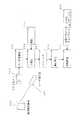
本発明による一実施例を図面を参照して説明する。図1は距離計測装置の構成を示すものである。レーザ投光器101によって、被測定対象物102にレーザを照射、停止を複数回行い、それに同期させてCCDカメラ103により被測定対象物102を撮像する。
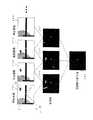
A/D変換器104で映像信号をデジタル化し、照射時画像105、停止時の画像106を別のメモリに記憶する。レーザの照射、停止ごとに照射画像105から停止画像106を差し引いた画像(差画像)を求め、それらを最小値検出回路107により「差画像の最小値」を各画素おきに求め記憶する。 図2に撮像される映像例を示す。レーザ照射時の画像を201〜202に、レーザ停止時の画像を203〜204に示す。屋外での映像では、レーザの波長成分を太陽光が含んでいるため、レーザの波長成分のみを透過するバンドパスフィルタを用いても、画像にはレーザ光以外の映像も撮像される。レーザ照射時の画像から停止時の画像を差し引いた差画像を205〜207に示す。各画像にはレーザ光が観測されるが、各撮像間隔時に画像の変化(レーザ照射時に明、停止時に暗)が起こった場所、すなわち動きのあった場所に外乱を生じる。これらの差画像205〜207の最小値を各画素ごとに算出すると、外乱は除去されレーザ光のみが抽出される(208)。
この「差画像の最小値」のデータは1ビットではなく階調を持っているためヒストグラム108により2値化閾値109を動的に決定することができ、照度変化の強い屋外環境下においてもレーザ光のみ検出できる。この閾値により2値化110、ラベリング111、重心検出112を行えば画像上でのレーザ位置が検出でき距離の算出114が可能となる。
【0006】
図2を用いて、被測定対象物を屋外に架線された電線とした場合の本発明の作用を説明する。
電線L(説明のため、若干太く描いている)の背景には街路樹Tがあり、鳥Bが飛んでおり、電線Lの所定の箇所に図1に示したレーザ投光器101によって、レーザ光Pを投射している。このようすを示すのが照射画像201である。
次に、レーザ光Pの投射を中止して、停止画像203を得る。このとき鳥Bは移動しており、街路樹Tの葉も風で揺れている。
したがって、照射画像201と停止画像203の差画像は205のようになる。すなわち、レーザ光Pの点、鳥B、風で揺れた街路樹Tの葉の部分が残る。
次に、レーザ光Pの投射を再開して、停止画像202を得る。このとき鳥Bは移動しており、街路樹Tの葉も風で揺れている。
したがって、停止画像203と照射画像202の差画像は206のようになる。すなわち、レーザ光Pの点、鳥B、風で揺れた街路樹Tの葉の部分が残る。
次に、レーザ光Pの投射を中止して、停止画像204を得る。このとき鳥Bは移動しており(画面から消えている)、街路樹Tの葉も風で揺れている。
したがって、照射画像202と停止画像204の差画像は207のようになる。すなわち、レーザ光Pの点、風で揺れた街路樹Tの葉の部分が残る。
最後に、差画像205,206,207の最小値(各画素は濃淡値が入っている)を求めると最小値の画像208となる。最小値の画像208では、レーザ光Pの点のみが強い輝度を保っている。
これにより、太陽光による背景がノイズとならず、レーザ光の照射点のみを抽出できたことになる。
【0007】
【発明の効果】
以上のような本発明では、低出力のレーザでもレーザ光のみを検出でき、照度の変化にも強い屋外用距離装置を実現できるものである。
したがって、屋外で作業するロボットシステム等に必要な対象ワークの距離測定装置として極めて有効である。
【図面の簡単な説明】
【図1】本発明の一実施例における距離計測装置の構成図
【図2】本実施例による映像を示す図
【図3】従来技術による距離計測装置の構成図
【符号の説明】
101:レーザ投光器
102:被測定対象物
103:CCDカメラ
104:A/D変換器
105:照射画像
106:停止画像
107:最小値検出
108:ヒストグラム
109:閾値
110:2値化
111:ラベリング
112:重心検出
113:光学パラメータまたはキャリグレーションテーブル
114:距離算出
201〜202:照射画像
203〜204:停止画像
205〜207:差画像
208:差画像の最小値
301:レーザ投光器
302:被測定対象物
303:CCDカメラ
304:A/D変換器
305:閾値
306:2値化
307:ラベリング
308:重心検出
309:光学パラメータまたはキャリブレーションテーブル
310:距離算出[0001]
BACKGROUND OF THE INVENTION
The present invention relates to a distance measuring device used outdoors, and more particularly to a distance measuring device that calculates a distance by a light cutting method.
[0002]
[Prior art]
In recent years, distance measuring apparatuses have been diversified, and non-contact measurement methods such as a light propagation time measurement method and a binocular stereoscopic method have been frequently used instead of the contact measurement method. In particular, the optical cutting method is common in applications such as robot handling because of accuracy.
Hereinafter, a configuration of a measuring apparatus using a general light cutting method will be described. FIG. 3 shows a configuration of an example of a distance measuring device by a conventional light cutting method. Laser light is irradiated to the
[0003]
[Problems to be solved by the invention]
However, in the above-described conventional configuration, it is assumed that the image of the laser projected onto the CCD camera is brighter than other locations on the image. There is still a problem in terms of safety. In addition, since the illuminance changes complicatedly outdoors, a threshold value cannot be determined in advance.
In view of this, the present inventor proposed a device that removes ambient light by performing simultaneous superimposition after image information obtained from a light receiving camera is converted, and discriminates only laser light (Japanese Patent Laid-Open No. Hei 8-94322). Issue gazette).
However, even in this proposal, when a moving object is captured, or when a background object shakes due to the influence of wind or the like, the image cannot be removed and remains as noise.
Accordingly, an object of the present invention is to provide an apparatus capable of measuring a distance with a low-power laser without causing noise even when a moving object is captured or a background object is shaken by the influence of wind or the like. To do.
[0004]
[Means for Solving the Problems]
In order to achieve this object, the present invention provides a laser irradiation means for irradiating a measurement target with laser light in a pulsed manner, and an image reading means for capturing an image of the measurement target in synchronization with the irradiation and stop of the laser light. And meansfor obtaining adifference image between the images read by the laser beam irradiation and stopping a plurality of times, obtaining a minimum valueof the difference imagesfor each pixel, and a binarization threshold value from the minimum value of the difference image. And a means for binarizing a minimum value of the difference image and detecting a light receiving position of the laser.
[0005]
DETAILED DESCRIPTION OF THE INVENTION
An embodiment according to the present invention will be described with reference to the drawings. FIG. 1 shows the configuration of a distance measuring device. The laser projector 101 irradiates and stops the laser beam to the
The video signal is digitized by the A /
Since this “minimum value of the difference image” has gradation rather than 1 bit, the binarization threshold 109 can be dynamically determined by the
[0006]
With reference to FIG. 2, the operation of the present invention when the object to be measured is an electric wire wired outdoors will be described.
The background of the electric wire L (drawn slightly thick for the sake of explanation) is a roadside tree T, a bird B is flying, and a laser beam P shown by a laser projector 101 shown in FIG. Is projected. The irradiation image 201 shows this.
Next, the projection of the laser beam P is stopped, and a stop image 203 is obtained. At this time, the bird B is moving, and the leaves of the roadside tree T are also swaying in the wind.
Therefore, the difference image between the irradiation image 201 and the stop image 203 is 205. That is, the point of the laser beam P, the bird B, and the leaves of the roadside tree T swayed by the wind remain.
Next, the projection of the laser beam P is resumed, and the
Therefore, the difference image between the stop image 203 and the
Next, the projection of the laser beam P is stopped, and a stop image 204 is obtained. At this time, the bird B is moving (disappearing from the screen), and the leaves of the roadside tree T are also shaken by the wind.
Therefore, the difference image between the
Finally, when the minimum value of each of the
As a result, the background from sunlight does not become noise, and only the irradiation point of the laser light can be extracted.
[0007]
【The invention's effect】
In the present invention as described above, it is possible to realize an outdoor distance device that can detect only laser light even with a low-power laser and is resistant to changes in illuminance.
Therefore, it is extremely effective as a distance measuring device for a target work necessary for a robot system or the like that works outdoors.
[Brief description of the drawings]
FIG. 1 is a configuration diagram of a distance measuring device according to an embodiment of the present invention. FIG. 2 is a diagram showing an image according to the embodiment. FIG. 3 is a configuration diagram of a distance measuring device according to the prior art.
101: Laser projector 102: Object to be measured 103: CCD camera 104: A / D converter 105: Irradiation image 106: Stop image 107: Minimum value detection 108: Histogram 109: Threshold 110: Binarization 111: Labeling 112: Center-of-gravity detection 113: Optical parameter or calibration table 114: Distance calculation 201-202: Irradiation images 203-204: Stop image 205-207: Difference image 208: Minimum value of difference image 301: Laser projector 302: Object to be measured 303: CCD camera 304: A / D converter 305: threshold 306: binarization 307: labeling 308: center of gravity detection 309: optical parameter or calibration table 310: distance calculation
Claims (1)
Translated fromJapanese前記レーザ光の照射、停止に同期させて、測定対象物の画像を取り込む画像読込み手段と、
複数回のレーザ光の照射、停止により読み込まれる各画像間の差画像を求め、それらの差画像の最小値を画素ごとに求める手段と、
前記差画像の最小値から2値化閾値を決定する手段と、
前記差画像の最小値を2値化し、レーザの受光位置を検出する手段と、を備えたことを特徴とする屋外用距離計測装置。Laser irradiation means for irradiating the measurement target with laser light in a pulsed manner;
Image reading means for capturing an image of a measurement object in synchronization with the irradiation and stopping of the laser beam;
Meansfor obtaining adifference image between the images read by irradiation and stopping of the laser light a plurality of times, and obtaining a minimum valueof the difference imagesfor each pixel ;
Means for determining a binarization threshold from the minimum value of the difference image;
Means for binarizing a minimum value of the difference image, and detecting a light receiving position of the laser.
Priority Applications (8)
| Application Number | Priority Date | Filing Date | Title |
|---|---|---|---|
| JP04736697AJP3909377B2 (en) | 1997-02-14 | 1997-02-14 | Outdoor distance measuring device |
| US09/355,707US6331887B1 (en) | 1997-02-14 | 1998-02-12 | Outdoor range finder |
| CA002281551ACA2281551A1 (en) | 1997-02-14 | 1998-02-12 | Outdoor range finder |
| EP98902214AEP1008831B1 (en) | 1997-02-14 | 1998-02-12 | Outdoor range finder |
| KR1019997007374AKR20000071087A (en) | 1997-02-14 | 1998-02-12 | Outdoor range finder |
| PCT/JP1998/000594WO1998036238A1 (en) | 1997-02-14 | 1998-02-12 | Outdoor range finder |
| DE69827275TDE69827275D1 (en) | 1997-02-14 | 1998-02-12 | DISTANCE KNIVES FOR OUTDOOR USE |
| TW087102028ATW412632B (en) | 1997-02-14 | 1998-02-13 | Outdoor range finder |
Applications Claiming Priority (1)
| Application Number | Priority Date | Filing Date | Title |
|---|---|---|---|
| JP04736697AJP3909377B2 (en) | 1997-02-14 | 1997-02-14 | Outdoor distance measuring device |
Publications (2)
| Publication Number | Publication Date |
|---|---|
| JPH10227609A JPH10227609A (en) | 1998-08-25 |
| JP3909377B2true JP3909377B2 (en) | 2007-04-25 |
Family
ID=12773121
Family Applications (1)
| Application Number | Title | Priority Date | Filing Date |
|---|---|---|---|
| JP04736697AExpired - Fee RelatedJP3909377B2 (en) | 1997-02-14 | 1997-02-14 | Outdoor distance measuring device |
Country Status (8)
| Country | Link |
|---|---|
| US (1) | US6331887B1 (en) |
| EP (1) | EP1008831B1 (en) |
| JP (1) | JP3909377B2 (en) |
| KR (1) | KR20000071087A (en) |
| CA (1) | CA2281551A1 (en) |
| DE (1) | DE69827275D1 (en) |
| TW (1) | TW412632B (en) |
| WO (1) | WO1998036238A1 (en) |
Families Citing this family (36)
| Publication number | Priority date | Publication date | Assignee | Title |
|---|---|---|---|---|
| US6732369B1 (en) | 1995-10-02 | 2004-05-04 | Starsight Telecast, Inc. | Systems and methods for contextually linking television program information |
| US6323911B1 (en) | 1995-10-02 | 2001-11-27 | Starsight Telecast, Inc. | System and method for using television schedule information |
| US6556245B1 (en) | 1999-03-08 | 2003-04-29 | Larry Allan Holmberg | Game hunting video camera |
| US8240077B2 (en) | 2002-03-04 | 2012-08-14 | Larry Holmberg | Range finder for weapons |
| US6615531B1 (en) | 2002-03-04 | 2003-09-09 | Larry Holmberg | Range finder |
| US7574824B2 (en)* | 2006-01-06 | 2009-08-18 | Larry Holmberg | Device mount for a firearm |
| US7643132B2 (en) | 2002-03-04 | 2010-01-05 | Larry Holmberg | Range finder |
| IL133835A (en)* | 1999-12-30 | 2003-10-31 | Rafael Armament Dev Authority | In-flight boresight |
| EP1273928A1 (en)* | 2001-07-06 | 2003-01-08 | Leica Geosystems AG | Method and device for suppressing electromagnetic background radiation in an image |
| WO2003008909A1 (en)* | 2001-07-17 | 2003-01-30 | Leica Geosystems Ag | Range finder with sighting device |
| US8156680B2 (en) | 2002-03-04 | 2012-04-17 | Larry Holmberg | Device mounting system for a weapon |
| WO2003089950A2 (en)* | 2002-04-15 | 2003-10-30 | Toolz, Ltd. | Distance measurement device |
| US7050625B2 (en)* | 2002-10-21 | 2006-05-23 | Hewlett-Packard Development Company, L.P. | Method and digital camera for indicating when image data has been captured for a three-dimensional target object |
| US7375801B1 (en) | 2005-04-13 | 2008-05-20 | The United States Of America As Represented By The Administrator Of The National Aeronautics And Space Administration | Video sensor with range measurement capability |
| WO2006133029A2 (en)* | 2005-06-03 | 2006-12-14 | Gilmore Sports Concepts, Inc. | Combination red dot sight and range indicator apparatus |
| US20070146482A1 (en)* | 2005-12-23 | 2007-06-28 | Branislav Kiscanin | Method of depth estimation from a single camera |
| US7647922B2 (en)* | 2006-06-30 | 2010-01-19 | Larry Holmberg | Adaptor for device mount |
| US20080001057A1 (en)* | 2006-06-30 | 2008-01-03 | Larry Holmberg | Device mount |
| US7506643B2 (en) | 2006-06-30 | 2009-03-24 | Larry Holmberg | Crossbow device mount |
| JP4315175B2 (en)* | 2006-08-10 | 2009-08-19 | 日産自動車株式会社 | Photodetection method and photodetection device |
| US7594352B2 (en)* | 2006-10-17 | 2009-09-29 | Larry Holmberg | Device mount with stabilizing function |
| US7891131B2 (en) | 2007-01-05 | 2011-02-22 | Larry Holmberg | Device mount system for a weapon |
| US7739822B1 (en) | 2007-01-09 | 2010-06-22 | Larry Holmberg | Method and device for mounting an accessory to a firearm |
| US7780363B1 (en) | 2008-01-17 | 2010-08-24 | Larry Holmberg | Device for mounting imaging equipment to a bow and method of recording a hunt |
| US8024884B2 (en) | 2009-06-16 | 2011-09-27 | Larry Holmberg | Electronic device mount system for weapons |
| US8161674B2 (en) | 2009-06-16 | 2012-04-24 | Larry Holmberg | Electronic device mount system with strap |
| US8497981B2 (en)* | 2009-09-15 | 2013-07-30 | Qualcomm Incorporated | Small form-factor size sensor |
| US8396685B2 (en) | 2009-09-15 | 2013-03-12 | Qualcomm Incorporated | Small form-factor distance sensor |
| CN101963696A (en)* | 2010-08-19 | 2011-02-02 | 山东神戎电子股份有限公司 | Night-vision device with ranging function |
| US8656625B2 (en) | 2010-12-29 | 2014-02-25 | Larry Holmberg | Accessory mount |
| US8656624B2 (en) | 2010-12-29 | 2014-02-25 | Larry Holmberg | Universal device mount |
| CN102749702B (en)* | 2012-06-28 | 2014-04-16 | 北京航空航天大学 | Red exposure eliminating method of hand-held semiconductor laser active night-vision device |
| US9043146B2 (en)* | 2013-06-19 | 2015-05-26 | The Boeing Company | Systems and methods for tracking location of movable target object |
| JP6956659B2 (en)* | 2018-03-19 | 2021-11-02 | 三菱電機株式会社 | Image processing equipment and laser irradiation equipment |
| CN109709974B (en)* | 2019-01-04 | 2021-01-19 | 南京航空航天大学 | Two-dimensional space guiding and positioning method based on laser ranging |
| CN114046768B (en)* | 2021-11-10 | 2023-09-26 | 重庆紫光华山智安科技有限公司 | Laser ranging method, device, laser ranging equipment and storage medium |
Family Cites Families (5)
| Publication number | Priority date | Publication date | Assignee | Title |
|---|---|---|---|---|
| US3463588A (en)* | 1966-12-30 | 1969-08-26 | United Aircraft Corp | Radar system |
| JPS54154351A (en)* | 1978-05-25 | 1979-12-05 | Canon Inc | Distance measuring device |
| US4678329A (en)* | 1985-10-18 | 1987-07-07 | Calspan Corporation | Automatically guided vehicle control system |
| JPH06344144A (en)* | 1993-06-04 | 1994-12-20 | Mitsubishi Heavy Ind Ltd | Method for measuring groove shape of member to be welded |
| JPH08177263A (en)* | 1994-12-21 | 1996-07-09 | Mitsubishi Heavy Ind Ltd | Method for detecting opening or closing of car door |
- 1997
- 1997-02-14JPJP04736697Apatent/JP3909377B2/ennot_activeExpired - Fee Related
- 1998
- 1998-02-12DEDE69827275Tpatent/DE69827275D1/ennot_activeExpired - Lifetime
- 1998-02-12KRKR1019997007374Apatent/KR20000071087A/ennot_activeCeased
- 1998-02-12EPEP98902214Apatent/EP1008831B1/ennot_activeExpired - Lifetime
- 1998-02-12WOPCT/JP1998/000594patent/WO1998036238A1/ennot_activeApplication Discontinuation
- 1998-02-12USUS09/355,707patent/US6331887B1/ennot_activeExpired - Lifetime
- 1998-02-12CACA002281551Apatent/CA2281551A1/ennot_activeAbandoned
- 1998-02-13TWTW087102028Apatent/TW412632B/ennot_activeIP Right Cessation
Also Published As
| Publication number | Publication date |
|---|---|
| US6331887B1 (en) | 2001-12-18 |
| JPH10227609A (en) | 1998-08-25 |
| DE69827275D1 (en) | 2004-12-02 |
| TW412632B (en) | 2000-11-21 |
| EP1008831A4 (en) | 2001-02-07 |
| KR20000071087A (en) | 2000-11-25 |
| CA2281551A1 (en) | 1998-08-20 |
| EP1008831A1 (en) | 2000-06-14 |
| WO1998036238A1 (en) | 1998-08-20 |
| EP1008831B1 (en) | 2004-10-27 |
| EP1008831A8 (en) | 2004-09-29 |
Similar Documents
| Publication | Publication Date | Title |
|---|---|---|
| JP3909377B2 (en) | Outdoor distance measuring device | |
| JP2000193601A (en) | Surface defect inspecting device | |
| JPH08313454A (en) | Image processing device | |
| JP2004132773A (en) | Vegetable gloss inspection device | |
| JP2005249503A (en) | Pantograph slip board inspection device. | |
| JP2006250574A (en) | Rail joint plate fastening bolt dropout detection device | |
| JP3506161B2 (en) | Agricultural and fishery product appearance inspection device | |
| CN209087158U (en) | Object early warning system waterborne | |
| JPH0814849A (en) | Three-dimensional shape detection method for solder | |
| JPH043820B2 (en) | ||
| JPS5920805A (en) | Configuration inspecting device for cubic body | |
| JPH07128347A (en) | Optical imaging and processing type vehicle sensor | |
| JP2973153B2 (en) | Coil tip shape detection device | |
| JPH0477951B2 (en) | ||
| JPS6129704A (en) | Measuring method | |
| JP2922904B2 (en) | Monitoring method by TV camera and monitoring device | |
| JPS62150488A (en) | Binarization method | |
| JP3915753B2 (en) | Image detection device | |
| JP2006098101A (en) | Defect detection method and defect detection device of plate body | |
| JPH11132957A (en) | Method and apparatus for detection of surface defect | |
| JP2006258649A (en) | Surface inspection device | |
| JP2004325397A (en) | Distance measuring device | |
| JPH0771285B2 (en) | Gray image processing method | |
| JPH0498148A (en) | Soldering bridge inspection device | |
| JPH06331488A (en) | Vapor leakage detector |
Legal Events
| Date | Code | Title | Description |
|---|---|---|---|
| A131 | Notification of reasons for refusal | Free format text:JAPANESE INTERMEDIATE CODE: A131 Effective date:20060609 | |
| A521 | Written amendment | Free format text:JAPANESE INTERMEDIATE CODE: A523 Effective date:20060629 | |
| TRDD | Decision of grant or rejection written | ||
| A01 | Written decision to grant a patent or to grant a registration (utility model) | Free format text:JAPANESE INTERMEDIATE CODE: A01 Effective date:20061208 | |
| A521 | Written amendment | Free format text:JAPANESE INTERMEDIATE CODE: A821 Effective date:20061222 | |
| A711 | Notification of change in applicant | Free format text:JAPANESE INTERMEDIATE CODE: A711 Effective date:20061222 | |
| A61 | First payment of annual fees (during grant procedure) | Free format text:JAPANESE INTERMEDIATE CODE: A61 Effective date:20061226 | |
| A521 | Written amendment | Free format text:JAPANESE INTERMEDIATE CODE: A821 Effective date:20061222 | |
| R150 | Certificate of patent or registration of utility model | Free format text:JAPANESE INTERMEDIATE CODE: R150 | |
| FPAY | Renewal fee payment (event date is renewal date of database) | Free format text:PAYMENT UNTIL: 20110202 Year of fee payment:4 | |
| FPAY | Renewal fee payment (event date is renewal date of database) | Free format text:PAYMENT UNTIL: 20120202 Year of fee payment:5 | |
| FPAY | Renewal fee payment (event date is renewal date of database) | Free format text:PAYMENT UNTIL: 20120202 Year of fee payment:5 | |
| FPAY | Renewal fee payment (event date is renewal date of database) | Free format text:PAYMENT UNTIL: 20130202 Year of fee payment:6 | |
| FPAY | Renewal fee payment (event date is renewal date of database) | Free format text:PAYMENT UNTIL: 20140202 Year of fee payment:7 | |
| LAPS | Cancellation because of no payment of annual fees |