JP3905867B2 - Rechargeable vacuum cleaner - Google Patents
Rechargeable vacuum cleanerDownload PDFInfo
- Publication number
- JP3905867B2 JP3905867B2JP2003198203AJP2003198203AJP3905867B2JP 3905867 B2JP3905867 B2JP 3905867B2JP 2003198203 AJP2003198203 AJP 2003198203AJP 2003198203 AJP2003198203 AJP 2003198203AJP 3905867 B2JP3905867 B2JP 3905867B2
- Authority
- JP
- Japan
- Prior art keywords
- secondary battery
- heat transfer
- vacuum cleaner
- charger
- charging
- Prior art date
- Legal status (The legal status is an assumption and is not a legal conclusion. Google has not performed a legal analysis and makes no representation as to the accuracy of the status listed.)
- Expired - Fee Related
Links
Images


Classifications
- H—ELECTRICITY
- H01—ELECTRIC ELEMENTS
- H01M—PROCESSES OR MEANS, e.g. BATTERIES, FOR THE DIRECT CONVERSION OF CHEMICAL ENERGY INTO ELECTRICAL ENERGY
- H01M10/00—Secondary cells; Manufacture thereof
- H01M10/42—Methods or arrangements for servicing or maintenance of secondary cells or secondary half-cells
- H01M10/44—Methods for charging or discharging
- H01M10/441—Methods for charging or discharging for several batteries or cells simultaneously or sequentially
- A—HUMAN NECESSITIES
- A47—FURNITURE; DOMESTIC ARTICLES OR APPLIANCES; COFFEE MILLS; SPICE MILLS; SUCTION CLEANERS IN GENERAL
- A47L—DOMESTIC WASHING OR CLEANING; SUCTION CLEANERS IN GENERAL
- A47L9/00—Details or accessories of suction cleaners, e.g. mechanical means for controlling the suction or for effecting pulsating action; Storing devices specially adapted to suction cleaners or parts thereof; Carrying-vehicles specially adapted for suction cleaners
- A47L9/28—Installation of the electric equipment, e.g. adaptation or attachment to the suction cleaner; Controlling suction cleaners by electric means
- A47L9/2805—Parameters or conditions being sensed
- A—HUMAN NECESSITIES
- A47—FURNITURE; DOMESTIC ARTICLES OR APPLIANCES; COFFEE MILLS; SPICE MILLS; SUCTION CLEANERS IN GENERAL
- A47L—DOMESTIC WASHING OR CLEANING; SUCTION CLEANERS IN GENERAL
- A47L9/00—Details or accessories of suction cleaners, e.g. mechanical means for controlling the suction or for effecting pulsating action; Storing devices specially adapted to suction cleaners or parts thereof; Carrying-vehicles specially adapted for suction cleaners
- A47L9/28—Installation of the electric equipment, e.g. adaptation or attachment to the suction cleaner; Controlling suction cleaners by electric means
- A47L9/2836—Installation of the electric equipment, e.g. adaptation or attachment to the suction cleaner; Controlling suction cleaners by electric means characterised by the parts which are controlled
- A47L9/2842—Suction motors or blowers
- A—HUMAN NECESSITIES
- A47—FURNITURE; DOMESTIC ARTICLES OR APPLIANCES; COFFEE MILLS; SPICE MILLS; SUCTION CLEANERS IN GENERAL
- A47L—DOMESTIC WASHING OR CLEANING; SUCTION CLEANERS IN GENERAL
- A47L9/00—Details or accessories of suction cleaners, e.g. mechanical means for controlling the suction or for effecting pulsating action; Storing devices specially adapted to suction cleaners or parts thereof; Carrying-vehicles specially adapted for suction cleaners
- A47L9/28—Installation of the electric equipment, e.g. adaptation or attachment to the suction cleaner; Controlling suction cleaners by electric means
- A47L9/2836—Installation of the electric equipment, e.g. adaptation or attachment to the suction cleaner; Controlling suction cleaners by electric means characterised by the parts which are controlled
- A47L9/2852—Elements for displacement of the vacuum cleaner or the accessories therefor, e.g. wheels, casters or nozzles
- A—HUMAN NECESSITIES
- A47—FURNITURE; DOMESTIC ARTICLES OR APPLIANCES; COFFEE MILLS; SPICE MILLS; SUCTION CLEANERS IN GENERAL
- A47L—DOMESTIC WASHING OR CLEANING; SUCTION CLEANERS IN GENERAL
- A47L9/00—Details or accessories of suction cleaners, e.g. mechanical means for controlling the suction or for effecting pulsating action; Storing devices specially adapted to suction cleaners or parts thereof; Carrying-vehicles specially adapted for suction cleaners
- A47L9/28—Installation of the electric equipment, e.g. adaptation or attachment to the suction cleaner; Controlling suction cleaners by electric means
- A47L9/2857—User input or output elements for control, e.g. buttons, switches or displays
- A—HUMAN NECESSITIES
- A47—FURNITURE; DOMESTIC ARTICLES OR APPLIANCES; COFFEE MILLS; SPICE MILLS; SUCTION CLEANERS IN GENERAL
- A47L—DOMESTIC WASHING OR CLEANING; SUCTION CLEANERS IN GENERAL
- A47L9/00—Details or accessories of suction cleaners, e.g. mechanical means for controlling the suction or for effecting pulsating action; Storing devices specially adapted to suction cleaners or parts thereof; Carrying-vehicles specially adapted for suction cleaners
- A47L9/28—Installation of the electric equipment, e.g. adaptation or attachment to the suction cleaner; Controlling suction cleaners by electric means
- A47L9/2868—Arrangements for power supply of vacuum cleaners or the accessories thereof
- A47L9/2873—Docking units or charging stations
- A—HUMAN NECESSITIES
- A47—FURNITURE; DOMESTIC ARTICLES OR APPLIANCES; COFFEE MILLS; SPICE MILLS; SUCTION CLEANERS IN GENERAL
- A47L—DOMESTIC WASHING OR CLEANING; SUCTION CLEANERS IN GENERAL
- A47L9/00—Details or accessories of suction cleaners, e.g. mechanical means for controlling the suction or for effecting pulsating action; Storing devices specially adapted to suction cleaners or parts thereof; Carrying-vehicles specially adapted for suction cleaners
- A47L9/28—Installation of the electric equipment, e.g. adaptation or attachment to the suction cleaner; Controlling suction cleaners by electric means
- A47L9/2868—Arrangements for power supply of vacuum cleaners or the accessories thereof
- A47L9/2884—Details of arrangements of batteries or their installation
- A—HUMAN NECESSITIES
- A47—FURNITURE; DOMESTIC ARTICLES OR APPLIANCES; COFFEE MILLS; SPICE MILLS; SUCTION CLEANERS IN GENERAL
- A47L—DOMESTIC WASHING OR CLEANING; SUCTION CLEANERS IN GENERAL
- A47L9/00—Details or accessories of suction cleaners, e.g. mechanical means for controlling the suction or for effecting pulsating action; Storing devices specially adapted to suction cleaners or parts thereof; Carrying-vehicles specially adapted for suction cleaners
- A47L9/28—Installation of the electric equipment, e.g. adaptation or attachment to the suction cleaner; Controlling suction cleaners by electric means
- A47L9/2889—Safety or protection devices or systems, e.g. for prevention of motor over-heating or for protection of the user
- H—ELECTRICITY
- H02—GENERATION; CONVERSION OR DISTRIBUTION OF ELECTRIC POWER
- H02J—CIRCUIT ARRANGEMENTS OR SYSTEMS FOR SUPPLYING OR DISTRIBUTING ELECTRIC POWER; SYSTEMS FOR STORING ELECTRIC ENERGY
- H02J7/00—Circuit arrangements for charging or depolarising batteries or for supplying loads from batteries
- H02J7/0042—Circuit arrangements for charging or depolarising batteries or for supplying loads from batteries characterised by the mechanical construction
- H02J7/0045—Circuit arrangements for charging or depolarising batteries or for supplying loads from batteries characterised by the mechanical construction concerning the insertion or the connection of the batteries
- Y—GENERAL TAGGING OF NEW TECHNOLOGICAL DEVELOPMENTS; GENERAL TAGGING OF CROSS-SECTIONAL TECHNOLOGIES SPANNING OVER SEVERAL SECTIONS OF THE IPC; TECHNICAL SUBJECTS COVERED BY FORMER USPC CROSS-REFERENCE ART COLLECTIONS [XRACs] AND DIGESTS
- Y02—TECHNOLOGIES OR APPLICATIONS FOR MITIGATION OR ADAPTATION AGAINST CLIMATE CHANGE
- Y02E—REDUCTION OF GREENHOUSE GAS [GHG] EMISSIONS, RELATED TO ENERGY GENERATION, TRANSMISSION OR DISTRIBUTION
- Y02E60/00—Enabling technologies; Technologies with a potential or indirect contribution to GHG emissions mitigation
- Y02E60/10—Energy storage using batteries
Landscapes
- Engineering & Computer Science (AREA)
- Mechanical Engineering (AREA)
- Power Engineering (AREA)
- General Chemical & Material Sciences (AREA)
- Chemical Kinetics & Catalysis (AREA)
- Electrochemistry (AREA)
- Chemical & Material Sciences (AREA)
- Manufacturing & Machinery (AREA)
- Robotics (AREA)
- Electric Vacuum Cleaner (AREA)
- Secondary Cells (AREA)
- Charge And Discharge Circuits For Batteries Or The Like (AREA)
- Electric Suction Cleaners (AREA)
- Battery Mounting, Suspending (AREA)
Description
Translated fromJapanese【0001】
【発明の属する技術分野】
本発明は、充電式電気掃除機に関する。
【0002】
【従来の技術】
従来、充電式電気掃除機及びその充電式電気掃除機の二次電池を充電するための充電器について様々な発明が提案され、実用化されている。このような充電式電気掃除機の充電において特に留意すべき点の一つは、温度が高い二次電池に対して充電を行うと二次電池の寿命が短くなるという点である。
【0003】
そこで、二次電池の温度を測定するサーミスタを設け、サーミスタの測定結果が適正充電温度(例えば、10〜30℃)より高い場合には充電を行わず、サーミスタの測定結果が適正充電温度範囲内となった場合に充電を開始するように制御する制御手段を備えたものが知られている。
【0004】
このような制御手段を備えた充電式電気掃除においては、掃除中に二次電池が放電終止電圧に達したために二次電池の充電を行おうとしても、掃除中には二次電池の温度が40〜50℃に達している場合が多く、二次電池の温度が適正充電温度に下がるまで待たなければならない。二次電池はハウジング内に収納されているために放熱性が低く、自然放熱により適正充電温度に下がるまで待っていたのでは長時間にわたって掃除を中断しなければならない場合がある。
【0005】
そこで、高温になっている二次電池の温度を速やかに低下させて二次電池の充電が可能になるまでの待ち時間を短縮するようにした発明が提案されている(例えば、特許文献1参照)。
【0006】
この特許文献1に開示された発明によれば、二次電池の充電のために充電式電気掃除機を充電器(ACアダプタ本体)に結合したときに、充電器内と充電式電気掃除機内とを連通するとともに二次電池がその途中に位置する風路を形成している。そして、充電器に設けられた送風機を駆動させることによりその風路内に冷却風を流し、この冷却風によって二次電池を強制的に空冷している。
【0007】
【特許文献1】
特開2002−65535公報
【0008】
【発明が解決しようとする課題】
しかし、上述した特許文献1に開示された発明では、二次電池を空冷するための冷却風が流れる風路を充電器内と充電式電気掃除機内とに形成しなければならず、構造が複雑になる。
【0009】
また、充電式電気掃除機内に風路を形成することにより充電式電気掃除機が大型化し、家電製品全般に対する要望である小型化に反することになる。
【0010】
さらに、充電器においては、充電のための機構のほかに冷却のための送風機やこの送風機に付随する様々な機構を設けなければならず、充電器が大型化し、高価格となる。
【0011】
本発明の目的は、二次電池の充電時において、高温となっている二次電池の温度を簡単な構造で速やかに低下させることである。
【0012】
【課題を解決するための手段】
本発明の充電式電気掃除機は、前記ハウジングに形成された二次電池収納部に収納された二次電池に熱的に接続された第1伝熱面部を有する伝熱部材を具備し、前記伝熱部材は、前記二次電池の充電のために前記充電器に結合されたときに前記充電器に設けられた伝熱部の第2伝熱面部に前記第1伝熱面部が面接触する位置に位置付けられて前記ハウジングを構成する材料よりも熱伝導率の高い材料で形成されており、前記二次電池収納部内に収納された前記二次電池を保持する閉止位置と前記二次電池を前記二次電池収納部に対して出し入れ可能とする開放位置とに位置変更可能に前記ハウジングに取り付けられた電池カバーであるので、二次電池の充電のために充電式電気掃除機を充電器に結合したとき、二次電池に熱的に接続されている伝熱部材の第1伝熱面部と充電器に設けられている伝熱部の第2伝熱面部とが面接触し、二次電池の熱が伝熱部材と伝熱部とを伝わって放熱され、二次電池の温度が速やかに低下する。
【0013】
【発明の実施の形態】
本発明の第1の実施の形態を図1ないし図10に基づいて説明する。図1は、充電式電気掃除機1の外観構成を示す斜視図である。この充電式電気掃除機1は、基体をなすハウジング2に対して着脱可能にホース3が接続され、ホース3の先端部に着脱可能に延長管4が接続され、延長管4の先端部に着脱可能に吸込口体5が取付けられている。ハウジング2の後方下部には走行用の一対の車輪6が取付けられ、ハウジング2の前方下部には走行用の一個の車輪6a(図2参照)が取付けられている。
【0014】
ハウジング2内部には、二次電池7と、この二次電池7を駆動源として駆動される負荷である電動送風機8とが収納されている。ホース3は、その基端が図示しない集塵室を介して電動送風機8の吸込側に連通するようにハウジング2に接続されている。ホース3の先端側であって延長管4が接続される箇所の近傍には、後方に向けてホース3から分岐された握り部9と、この握り部9を握った操作者の指で操作可能な範囲に位置する操作手段10とが設けられている。
【0015】
操作手段10は、電動送風機8の電源スイッチを兼ね、この電動送風機8をそれぞれ異なる駆動状態にする複数種類の運転モードを選択設定することができるように構成されている。具体的には、握り部9から延長管4の方向に向けて、運転モードの一つである停止設定用の操作ボタン、運転モードの一つである弱運転設定用の操作ボタン、運転モードの一つである強運転設定用の操作ボタンが一列に配設されている。
【0016】
図2は、ハウジング2の後端側底面部を示す斜視図である。ハウジング2は上部ケース2aと下部ケース2bとから形成されており、下部ケース2bには二次電池7が収納される二次電池収納部11が形成されている。二次電池7は、例えば円筒型のニッケルカドミウム電池、ニッケル水素電池、リチウムイオン電池等を複数本直列に接続し、熱収縮チューブで一つにまとめて構成されている。この二次電池7には、二次電池7の温度を検出する温度検出手段としてのサーミスタ12(図9参照)や過電流保護機構(図示せず)が設けられている。下部ケース2bの底面には、二次電池収納部11内に収納された二次電池7を保持する閉止位置と、二次電池7を二次電池収納部11に対して出し入れ可能とする開放位置とに着脱可能に伝熱部材である電池カバー13が取り付けられている。この電池カバー13の外面には、平坦な形状の第1伝熱面部13aが形成されている。
【0017】
図3及び図4は、二次電池収納部11の構造及び電池カバー13の取付構造を示す斜視図である。二次電池収納部11は下部ケース2bに形成された凹形状の収納空間であり、下部ケース2bの底面部に形成された長方形の開口14と、収納空間を形成するための一対の固定板15及び略コの字型に形成された押圧体である一つの可動部材16とにより形成されている。固定板15は、開口14の長辺の縁部に固定されて開口14と直交する向きに下部ケース2b内に延出している。可動部材16は、開口14の短辺の縁部に位置付けられる一対の垂直部16a,16bと垂直部16a,16bに連結されて開口14と略平行に対向する平行部16cとから形成され、一方の垂直部16aが開口14の一方の短辺の縁部に回動可能に取り付けられ、他方の垂直部16bにはネジ穴17が形成され、このネジ穴17を利用して開口14の他方の短辺の縁部にネジ止めされている。
【0018】
電池カバー13は、開口14内にほとんど隙間のない状態に収納されるサイズに形成された長方形の板状部材であり、一方の短辺の縁部には一対の凸部18が形成され、開口14の一方の短辺の縁部にはこれらの凸部18が嵌め込まれる凹部(図示せず)が形成されている。電池カバー13の他方の短辺の縁部には一対のネジ穴19が形成されている。これらのネジ穴19は、凸部18を凹部に嵌め込み、電池カバー13を二次電池収納部11内に収納された二次電池7を保持する閉止位置に位置させたとき、可動部材16に形成されたネジ穴17と重なり合う位置に位置付けられる。凸部18を凹部に嵌め込み、ネジ穴19とネジ穴17とを重ね合わせてこれらのネジ穴19,17にネジを螺合することにより、電池カバー13が閉止位置で下部ケース2bに固定される。
【0019】
下部ケース2bに固定されて閉止位置に位置する電池カバー13と二次電池収納部11に収納された二次電池7の電極側端面との間には、伝熱性とクッション性とを有する伝熱性クッション材20が介装されている。なお、この伝熱性クッション材20は二次電池7の電極側端面と電池カバー13との間に介装されていればよく、電池カバー13と別体とされる必要はなく、予め電池カバー13の内面に接着されていてもよい。
【0020】
電池カバー13は、上部ケース2aや下部ケース2bの材料よりも熱伝導率が高い材料で形成されている。例えば、上部ケース2aや下部ケース2bはABSが多く用いられるが、電池カバー13にはABSよりも熱伝導率の高い金属粉末を混合した樹脂材料や金属材料等が用いられている。伝熱性クッション材20の材料としては、上部ケース2aや下部ケース2bの材料よりも熱伝導率が高い材料、例えば、カーボンフィラーを所定量含有するスポンジラバー等が用いられている。
【0021】
二次電池収納部11内への二次電池7の収納は、以下の手順で行う。図3は下部ケース2bから取り外した電池カバー13が開放位置に位置する状態である。図3に示すように電池カバー13を下部ケース2bから取り外した後、二次電池7を開口14から二次電池収納部11内に収納する。つぎに、収納した二次電池7の開口14側の電極側端面上に伝熱性クッション材20を配置し、この伝熱性クッション材20を押えるようにして電池カバー13を開口14を閉止する位置に取り付ける。電池カバー13の取り付けは、電池カバー13に形成された凸部18を下部ケース2bに形成された凹部に嵌め込んで電池カバー13を仮止めし、電池カバー13のネジ穴19と可動部材16に形成されたネジ穴17とを位置合わせし、これらのネジ穴19,17にネジを螺合することにより行う。図2は、電池カバー13が閉止位置に位置する状態であり、二次電池収納部11内に収納された二次電池7が電池カバー13によって保持されている。
【0022】
電池カバー13を閉止位置で位置させるためのネジ止め時において、ネジを締め付けるにしたがって可動部材16が垂直部16a側に設けられている回動可能な取付部を支点として電池カバー13に接近する方向へ回動し、可動部材16の平行部16cと電池カバー13とにより二次電池7を押圧する力が次第に大きくなり、二次電池7の固定状態が次第に強固になる。また、ネジ穴19,17に螺合したネジの締付けにより可動部材16が電池カバー13に接近する方向へ回動することに伴い、二次電池7の電極側端面と伝熱性クッション材20との間、及び、伝熱性クッション材20と電池カバー13との間の接触部分の押圧力が強くなり、二次電池7と伝熱性クッション材20と電池カバー13との熱的な接続が強くなる。
【0023】
図5は、ハウジング2の後部側を示す斜視図である。ハウジング2の後部側には充電のために充電用端子21が設けられている。
【0024】
図6は、充電式電気掃除機1の二次電池7を充電する充電器22を示す斜視図である。二次電池7を充電する場合には、充電式電気掃除機1を充電器22に結合し、充電式電気掃除機1の充電用端子21と充電器22の充電用端子23とを接続する。
【0025】
充電器22は、中空状のケースである充電器本体24、充電用端子23、充電用端子23に接続された充電制御回路25(図9参照)、伝熱部26、ファン27、載置部28等により構成されている。
【0026】
図7及び図8は、二次電池7の充電のために充電式電気掃除機1を充電器22に結合した状態である。
【0027】
載置部28は充電器本体24の一部を構成する部分であり、二次電池7を充電するために充電式電気掃除機1を充電器22に結合したときにハウジング2の後端側が載置される。この載置部28は、ハウジング2の後端側の凸面形状部が嵌まり込む凹面形状に形成されている。
【0028】
伝熱部26は、充電器本体24から上方向きに突出する角筒状部材であり、その一面には平坦な形状の第2伝熱面部26aが形成され、二次電池7の充電のために充電式電気掃除機1を充電器22に結合したときに電池カバー13の第1伝熱面部13aが第2伝熱面部26aに面接触する位置に位置付けられている。第1伝熱面部13aと第2伝熱面部26aとは、互いに面接触が可能な平坦な形状に形成されている。伝熱部26は充電器本体24と一体に形成してもよく、又は、充電器本体24と別体に形成したものを充電器本体24に固定してもよい。また、本実施の形態の伝熱部26は角筒状に形成されているが、この伝熱部の形状は他の形状、例えば、円柱状でもよく、電池カバーの第1伝熱面部と面接触する第2伝熱面部を備えていればよい。この場合において、第1伝熱面部と第2伝熱面部とは、共に平坦な形状でもよく、又は、凸面状と凹面状とでもよい。この伝熱部26を構成する材料としては、空気よりも熱伝導率が高ければ伝熱性を高める効果を有するが、電池カバー13を形成する材料と同程度又はそれ以上の熱伝導率を有することが望ましい。また、この伝熱部26における第2伝熱面部26aのサイズは、電池カバー13の第1伝熱面部13aのサイズと同程度であることが好ましい。
【0029】
ファン27は、伝熱部26に取付けられており、伝熱部26からの放熱を促進する方向に送風する部材であり、充電器本体24内の空気を伝熱部26内を通して送風し、その上端の開口部分から排気する。このとき、送風された空気が伝熱部26の内側面に沿って流れることにより、伝熱部26からの放熱が促進される。
【0030】
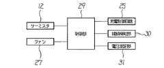
図9は、充電式電気掃除機1を充電器22に結合した状態における充電動作に関係する部分の電気的接続構造を示すブロック図である。充電器22にはCPUやROM及びRAM等から構成されるマイクロコンピュータ構成の制御部29が設けられており、この制御部29に対し、二次電池7の温度を測定するサーミスタ12、二次電池7に対する充電を行う充電制御回路25、ファン27、充電式電気掃除機1の充電用端子21と充電器22の充電用端子23とが接続されたことを検知するための接続検知部30、二次電池7の電圧を測定する電圧測定部31等が接続されている。
【0031】
このような構成において、充電式電気掃除機1による掃除中に二次電池7が放電終止電圧に達した場合には、ハウジング2に設けられている把持部32を把持して充電式電気掃除機1を持ち上げ、持ち上げた充電式電気掃除機1を下ろして図7及び図8に示すように充電器22に結合する。充電式電気掃除機1を充電器22に結合することにより、充電式電気掃除機1の充電用端子21と充電器22の充電用端子23とが接続され、二次電池7の温度が適正充電温度に下降した場合に充電が開始される。
【0032】
充電式電気掃除機1を充電器22に結合したとき、閉止位置に位置する電池カバー13の第1伝熱面部13aと充電器22に設けられている伝熱部26の第2伝熱面部26aとが面接触する。これにより、二次電池7と伝熱性クッション材20と電池カバー13とが既に熱的に接続されていることに加え、電池カバー13と伝熱部26とが熱的に接続されるので、二次電池7からの熱が伝熱性クッション材20と電池カバー13とを介して伝熱部26に到る伝熱通路が形成される。この伝熱通路が形成されることにより、二次電池7の熱はハウジング2内に籠もることなく伝熱通路を経由して伝熱部26に伝達される。さらに、ファン27を駆動させることにより効果的に充電式電気掃除機1外に放熱され、二次電池7の温度が速やかに低下し、二次電池7は短時間のうちに適正充電温度となる。
【0033】
しかも、この伝熱通路は、二次電池7と伝熱性クッション材20と電池カバー13と電池カバー13の第1伝熱面部13aと伝熱部26の第2伝熱面部26aとを接触させることにより形成されているので、構造が簡単であり、特許文献1に開示されたような風路を形成する場合に比べて充電式電気掃除機1の小型化を図ることができる。
【0034】
この二次電池7の充電時において、ファン27が駆動されることによりファン27により送風された空気が伝熱部26に当たり、伝熱部26からの放熱が促進される。これにより、二次電池7の温度低下がより一層速やかに行われ、二次電池7が適正充電温度に低下するまでの時間がさらに短くなる。
【0035】
また、ファン27により送風するということは、高速充電に対して特に大きな効果を発揮する。すなわち、高速充電においては、二次電池7からの発熱量が増えるだけでなく充電制御回路25からの発熱量も増える。発熱量が増えた充電制御回路25に対してファン27により送風される空気を当てることにより充電制御回路25の温度上昇を抑制でき、大電流による高速充電が可能となる。
【0036】
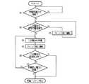
ここで、二次電池7の充電のために充電式電気掃除機1を充電器22に結合したときの制御部29による一連の制御動作を図10のフローチャートに基づいて説明する。
【0037】
まず、接続検知部30からの検知結果に基づき、充電用端子21と充電用端子23とが接続されているか否かが判断される(ステップS1)。充電用端子21,23が接続されている場合には(ステップS1のY)、サーミスタ12からの検知結果に基づいて二次電池7の温度が適正充電温度以内か否かが判断される(ステップS2)。二次電池7の温度が適正充電温度以上である場合には(ステップS2のN)、ファン27が“強”運転される(ステップS3)。ファン27が“強”運転されることにより、伝熱部26からの放熱が促進され、この伝熱部26に対して熱的に接続されている二次電池7の温度低下が促進される。
【0038】
ステップS2において二次電池7の温度が適正充電温度以内であると判断された場合は(ステップS2のY)、充電制御回路25が駆動されて二次電池7の充電が開始され(ステップS4)、この二次電池7の充電中はファン27が“弱”運転される(ステップS5)。二次電池7の充電中にファン27が“弱”運転されることにより、充電に伴う二次電池7での発熱が生じても、二次電池7の温度が適正充電温度以上に上昇することが阻止される。
【0039】
二次電池7の充電中は、二次電池7の温度が予め設定した温度上昇割合よりも大きくなったか否か、即ち、二次電池7の温度が急上昇したか否かがサーミスタ12からの検知結果に基づいて判断され(ステップS6)、及び、二次電池7の電圧が充電終止電圧に到達したか否かが電圧測定部31からの測定結果に基づいて判断される(ステップS7)。
【0040】
二次電池7の温度が急上昇した場合には(ステップS6のY)、充電異常が発生したことを意味するので、充電動作とファン27の駆動とを停止する(ステップS8)。また、二次電池7の電圧が充電終止電圧に到達した場合には(ステップS7のY)、それ以上充電を続ける必要がないので、充電動作とファン27の駆動とを停止する(ステップS8)。
【0041】
充電終了後は、把持部32を把持して充電式電気掃除機1を持ち上げ、充電式電気掃除機1と充電器22との結合を解除する。充電器22との結合を解除した充電式電気掃除機1の車輪6,6aを床面に着ければ、掃除を再開することが可能となる。
【0042】
本実施の形態では、伝熱部材である電池カバー13と伝熱性クッション材20とが、上部ケース2aや下部ケース2bに比べて熱伝導率の高い材料で形成されているため、二次電池7から伝熱性クッション材20と電池カバー13とを介して行われる伝熱部26への伝熱が良好に行われ、二次電池7から発生した熱がハウジング2に留まって二次電池7を保温するということが防止され、二次電池7の温度を適正充電温度内に速やかに低下させることができる。
【0043】
また、本実施の形態では、二次電池7の電極側端面と電池カバー13との間に伝熱性とクッション性とを有する伝熱性クッション材20が介装されているので、二次電池収納部11内で二次電池7を確実に固定することができ、また、収納した二次電池7を衝撃から保護することができ、さらに、二次電池7と電池カバー13との間に隙間ができることを防止して二次電池7と電池カバー13との間の熱的な接続を確実に行える。
【0044】
なお、本実施の形態では、伝熱性クッション材20を二次電池7と電池カバー13との間に介装した場合を例に挙げて説明したが、二次電池収納部11内での二次電池7の固定、及び、二次電池7の衝撃に対する保護という観点からは、二次電池7と可動部材16の平行部16cとの間に同様の伝熱性クッション材20を介装することが有効である。
【0045】
また、本実施の形態の充電器22では、従来構造の充電器に対して伝熱部26とファン27とを付加した構造であるので、簡単な構造によって充電時における二次電池7の温度低下を促進することができる。
【0046】
なお、本実施の形態では、伝熱部26とファン27とを設けた充電器22を例に挙げて説明したが、ファン27を設けずに伝熱部26のみを設けた場合であっても、充電時における二次電池7の温度低下促進の効果を得ることができる。
【0047】
本発明の第2の実施の形態を図11に基づいて説明する。なお、第1の実施の形態で説明した部分と同じ部分は同じ符号で示し、説明も省略する。本実施の形態の充電器33は横置き形式で充電を行う方式であり、その外観形状は第1の実施の形態(図6、図8)と略同じであるが、充電時における使用形態の向きが異なり、伝熱部26を床面に接触させる向きで使用される。
【0048】
二次電池7への充電時には、車輪6,6aを用いて充電式電気掃除機1を充電器33との結合位置に向けて後進させ、車輪6が伝熱部26を跨ぐようにしてハウジング2を伝熱部26の上に押し上げ、充電用端子21と充電用端子23とを接続する。これにより、電池カバー13の第1伝熱面部13aと伝熱部26の第2伝熱面部26aとが面接触する。
【0049】
この充電器33は、伝熱部26の床面からの高さ寸法は“H1”に設定され、車輪6の下端部からハウジング2の底面までの寸法“H2”より大きく設定されている。これにより、充電式電気掃除機1が充電器33に結合されているときには、車輪6は床面から離反し、充電式電気掃除機1の重量が電池カバー13を介して伝熱部26に作用する。このため、電池カバー13の第1伝熱面部13aと伝熱部26の第2伝熱面部26aとの面接触が確実に行われ、充電時における電池カバー13から伝熱部26への伝熱が良好に行われ、充電時において二次電池7の熱が伝熱性クッション材20と電池カバー13とを介して伝熱部26へ良好に伝熱され、二次電池7の温度が短時間で適正充電温度に低下する。
【0050】
本実施の形態では、充電式電気掃除機1と充電器33とを二次電池7の充電のために結合する操作を、充電式電気掃除機1を持ち上げることなく充電式電気掃除機1を充電器33に向けて車輪6,6aを用いて走行させることにより行える。これにより、充電式電気掃除機1を充電器33に結合する際の操作性を向上させることができる。
【0051】
【発明の効果】
本発明の充電式電気掃除機によれば、ハウジング内に収納された二次電池の充電時における二次電池からの放熱を簡単な構造により速やかに行うことができ、充電時における二次電池の温度を適正充電温度に短時間で低下させることができる。
【図面の簡単な説明】
【図1】本発明の第1の実施の形態の充電式電気掃除機を示す斜視図である。
【図2】充電式電気掃除機の一部を示す斜視図である。
【図3】二次電池の取付構造を示す分解斜視図である。
【図4】二次電池収納部の構造を示す斜視図である。
【図5】充電式電気掃除機の一部を示す斜視図である。
【図6】充電器を示す斜視図である。
【図7】二次電池の充電のために充電式電気掃除機を充電器に結合させた状態を示す斜視図である。
【図8】充電式電気掃除機を充電器に結合させた状態を示す側面図である。
【図9】充電動作に関係する部分の電気的接続構造を示すブロック図である。
【図10】充電動作を説明するフローチャートである。
【図11】本発明の第2の実施の形態における充電式電気掃除機を充電器に結合させた状態を示す側面図である。
【符号の説明】
1 充電式電気掃除機
2 ハウジング
7 二次電池
8 電動送風機
11 二次電池収納部
13 伝熱部材、電池カバー
13a 第1伝熱面部
16 押圧体
20 伝熱性クッション材
22 充電器
26 伝熱部
26a 第2伝熱面部
27 ファン
33 充電器[0001]
BACKGROUND OF THE INVENTION
The present invention also relatesto a rechargeable vacuumcleaner.
[0002]
[Prior art]
Conventionally, various inventions have been proposed and put into practical use for a rechargeable vacuum cleaner and a charger for charging a secondary battery of the rechargeable vacuum cleaner. One of the points to be particularly noted in charging such a rechargeable vacuum cleaner is that when a secondary battery having a high temperature is charged, the life of the secondary battery is shortened.
[0003]
Therefore, a thermistor for measuring the temperature of the secondary battery is provided, and charging is not performed when the thermistor measurement result is higher than the appropriate charging temperature (for example, 10 to 30 ° C.), and the thermistor measurement result is within the appropriate charging temperature range. What is provided with the control means which controls to start charge when it becomes is known.
[0004]
In rechargeable electric cleaning provided with such control means, even if an attempt is made to charge the secondary battery because the secondary battery has reached the end-of-discharge voltage during cleaning, the temperature of the secondary battery remains during cleaning. In many cases, the temperature reaches 40 to 50 ° C., and it is necessary to wait until the temperature of the secondary battery is lowered to an appropriate charging temperature. Since the secondary battery is housed in the housing, the heat dissipation is low, and cleaning may have to be interrupted for a long time if the secondary battery waits for the natural charging to drop to the appropriate charging temperature.
[0005]
In view of this, an invention has been proposed in which the temperature of a secondary battery that is at a high temperature is quickly lowered to shorten the waiting time until the secondary battery can be charged (see, for example, Patent Document 1). ).
[0006]
According to the invention disclosed in Patent Document 1, when the rechargeable vacuum cleaner is coupled to the charger (AC adapter main body) for charging the secondary battery, the charger, the rechargeable vacuum cleaner, The secondary battery forms an air passage located in the middle of the air. Then, by driving a blower provided in the charger, cooling air is caused to flow in the air passage, and the secondary battery is forcibly cooled by the cooling air.
[0007]
[Patent Document 1]
JP 2002-65535 A
[Problems to be solved by the invention]
However, in the invention disclosed in Patent Document 1 described above, an air passage through which cooling air for cooling the secondary battery flows must be formed in the charger and the rechargeable vacuum cleaner, and the structure is complicated. become.
[0009]
Moreover, by forming an air passage in the rechargeable vacuum cleaner, the rechargeable vacuum cleaner becomes larger, which is contrary to the downsizing that is a demand for home appliances in general.
[0010]
Furthermore, in the charger, in addition to the charging mechanism, a cooling blower and various mechanisms associated with the blower must be provided, and the charger becomes large and expensive.
[0011]
An object of the present invention is to quickly lower the temperature of a secondary battery that is at a high temperature with a simple structure when the secondary battery is charged.
[0012]
[Means for Solving the Problems]
The rechargeable vacuum cleaner of the present invention includes a heat transfer member having a first heat transfer surface portion thermally connected to a secondary battery stored in a secondary battery storage portion formed in the housing, When the heat transfer member is coupled to the charger for charging the secondary battery, the first heat transfer surface portion comes into surface contact with a second heat transfer surface portion of the heat transfer portion provided in the charger.A closed position for holding the secondary battery housed in the secondary battery housing portion and the secondary battery, wherein the secondary battery is made of a material having a higher thermal conductivity than the material constituting the housing. Since the battery cover is attached to the housing so that the position of the battery can be changed to an open position that allows the battery to be taken in and out of the secondary battery storage unit, a rechargeable vacuum cleaner is used as a charger for charging the secondary battery. When connected, it is thermally connected to the secondary battery. The first heat transfer surface portion of the heat transfer member and the second heat transfer surface portion of the heat transfer portion provided in the charger are in surface contact, and the heat of the secondary battery is transferred through the heat transfer member and the heat transfer portion to dissipate heat. As a result, the temperature of the secondary battery quickly decreases.
[0013]
DETAILED DESCRIPTION OF THE INVENTION
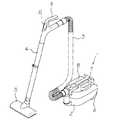
A first embodiment of the present invention will be described with reference to FIGS. FIG. 1 is a perspective view showing an external configuration of the rechargeable vacuum cleaner 1. This rechargeable vacuum cleaner 1 has a
[0014]
Inside the
[0015]
The operation means 10 also serves as a power switch for the electric blower 8 and is configured to be able to select and set a plurality of types of operation modes for setting the electric blower 8 in different driving states. Specifically, from the grip portion 9 toward the
[0016]
FIG. 2 is a perspective view showing the bottom surface of the rear end side of the
[0017]
3 and 4 are perspective views showing the structure of the
[0018]
The
[0019]
Between the
[0020]
The
[0021]
The
[0022]
When screwing to position the
[0023]
FIG. 5 is a perspective view showing the rear side of the
[0024]
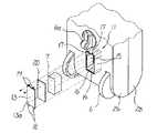
FIG. 6 is a perspective view showing a
[0025]
The
[0026]
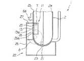
7 and 8 show a state in which the rechargeable vacuum cleaner 1 is coupled to the
[0027]
The mounting
[0028]
The
[0029]
The
[0030]
FIG. 9 is a block diagram showing an electrical connection structure of a portion related to a charging operation in a state where the rechargeable vacuum cleaner 1 is coupled to the
[0031]
In such a configuration, when the
[0032]
When the rechargeable vacuum cleaner 1 is coupled to the
[0033]
In addition, the heat transfer passages contact the
[0034]
When the
[0035]
In addition, blowing air by the
[0036]
Here, a series of control operations by the
[0037]
First, based on the detection result from the
[0038]
If it is determined in step S2 that the temperature of the
[0039]
While the
[0040]
If the temperature of the
[0041]
After the end of charging, the
[0042]
In the present embodiment, since the
[0043]
In the present embodiment, since the heat
[0044]
In the present embodiment, the case where the heat
[0045]
In addition, the
[0046]
In the present embodiment, the
[0047]
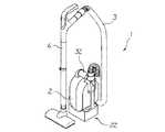
A second embodiment of the present invention will be described with reference to FIG. In addition, the same part as the part demonstrated in 1st Embodiment is shown with the same code | symbol, and description is also abbreviate | omitted. The
[0048]
When charging the
[0049]
In the
[0050]
In the present embodiment, the operation of coupling the rechargeable vacuum cleaner 1 and the
[0051]
【The invention's effect】
Accordingto the rechargeable vacuumcleaner of the present invention, it can be carried out quickly by a simple structure the heat radiation from the secondary battery during charging of the secondary battery housed in the housing, the secondary battery during charging The temperature can be lowered to the appropriate charging temperature in a short time.
[Brief description of the drawings]
FIG. 1 is a perspective view showing a rechargeable vacuum cleaner according to a first embodiment of the present invention.
FIG. 2 is a perspective view showing a part of the rechargeable vacuum cleaner.
FIG. 3 is an exploded perspective view showing a mounting structure of a secondary battery.
FIG. 4 is a perspective view showing a structure of a secondary battery storage unit.
FIG. 5 is a perspective view showing a part of the rechargeable vacuum cleaner.
FIG. 6 is a perspective view showing a charger.
FIG. 7 is a perspective view showing a state in which a rechargeable vacuum cleaner is coupled to a charger for charging a secondary battery.
FIG. 8 is a side view showing a state in which the rechargeable vacuum cleaner is coupled to the charger.
FIG. 9 is a block diagram showing an electrical connection structure of a portion related to a charging operation.
FIG. 10 is a flowchart illustrating a charging operation.
FIG. 11 is a side view showing a state in which the rechargeable vacuum cleaner according to the second embodiment of the present invention is coupled to a charger.
[Explanation of symbols]
DESCRIPTION OF SYMBOLS 1
Claims (3)
Translated fromJapanese前記ハウジングに形成された二次電池収納部に収納された二次電池に熱的に接続された第1伝熱面部を有する伝熱部材を具備し、
前記伝熱部材は、
前記二次電池の充電のために前記充電器に結合されたときに前記充電器に設けられた伝熱部の第2伝熱面部に前記第1伝熱面部が面接触する位置に位置付けられて前記ハウジングを構成する材料よりも熱伝導率の高い材料で形成されており、
前記二次電池収納部内に収納された前記二次電池を保持する閉止位置と前記二次電池を前記二次電池収納部に対して出し入れ可能とする開放位置とに位置変更可能に前記ハウジングに取り付けられた電池カバーである、
ことを特徴とする充電式電気掃除機。In a rechargeable vacuum cleaner in which a secondary battery and an electric blower using the secondary battery as a drive source are housed in a housing and coupled to a charger for charging the secondary battery,
A heat transfer member having a first heat transfer surface portion thermally connected to a secondary battery housed in a secondary battery housing portion formed in the housing;
The heat transfer member is
The first heat transfer surface portion is positioned in a surface contact with the second heat transfer surface portion of the heat transfer portion provided in the charger when coupled to the charger for charging the secondary battery.It is formed of a material having a higher thermal conductivity than the material constituting the housing,
The rechargeable battery is attached to the housing so that the position of the rechargeable battery can be changed between a closed position for holding the rechargeable battery housed in the rechargeable battery storage section and an open position where the rechargeable battery can be taken in and out of the rechargeable battery storage section. Battery cover,
A rechargeable vacuum cleaner characterized by that.
Priority Applications (4)
| Application Number | Priority Date | Filing Date | Title |
|---|---|---|---|
| JP2003198203AJP3905867B2 (en) | 2003-07-17 | 2003-07-17 | Rechargeable vacuum cleaner |
| US10/891,202US20050017681A1 (en) | 2003-07-17 | 2004-07-13 | Rechargeable vacuum cleaner system |
| EP04016570.6AEP1498999B1 (en) | 2003-07-17 | 2004-07-14 | Rechargeable vacuum cleaner system |
| CNB2004100589116ACN1305433C (en) | 2003-07-17 | 2004-07-19 | Rechargeable vacuum cleaner system |
Applications Claiming Priority (1)
| Application Number | Priority Date | Filing Date | Title |
|---|---|---|---|
| JP2003198203AJP3905867B2 (en) | 2003-07-17 | 2003-07-17 | Rechargeable vacuum cleaner |
Publications (2)
| Publication Number | Publication Date |
|---|---|
| JP2005034246A JP2005034246A (en) | 2005-02-10 |
| JP3905867B2true JP3905867B2 (en) | 2007-04-18 |
Family
ID=33475513
Family Applications (1)
| Application Number | Title | Priority Date | Filing Date |
|---|---|---|---|
| JP2003198203AExpired - Fee RelatedJP3905867B2 (en) | 2003-07-17 | 2003-07-17 | Rechargeable vacuum cleaner |
Country Status (4)
| Country | Link |
|---|---|
| US (1) | US20050017681A1 (en) |
| EP (1) | EP1498999B1 (en) |
| JP (1) | JP3905867B2 (en) |
| CN (1) | CN1305433C (en) |
Families Citing this family (53)
| Publication number | Priority date | Publication date | Assignee | Title |
|---|---|---|---|---|
| US7712182B2 (en)* | 2003-07-25 | 2010-05-11 | Milwaukee Electric Tool Corporation | Air flow-producing device, such as a vacuum cleaner or a blower |
| US20060022635A1 (en)* | 2004-07-30 | 2006-02-02 | Gpe International Limited | Battery chargers |
| US20060204383A1 (en)* | 2005-03-08 | 2006-09-14 | Hiroyuki Kushida | Electric vacuum cleaner |
| ATE446040T1 (en)* | 2005-08-11 | 2009-11-15 | Black & Decker Inc | HAND-HELD VACUUM CLEANER |
| JP4079962B2 (en)* | 2005-08-30 | 2008-04-23 | 株式会社東芝 | Electric vacuum cleaner |
| US7530140B2 (en)* | 2005-09-23 | 2009-05-12 | Royal Appliance Mfg. Co. | Vacuum cleaner with ultraviolet light source and ozone |
| USD564150S1 (en)* | 2006-03-16 | 2008-03-11 | Ab Electrolux | Combined handheld vacuum and base |
| JP4461114B2 (en) | 2006-03-30 | 2010-05-12 | 株式会社東芝 | Battery assembly system, battery assembly charging method and rechargeable vacuum cleaner |
| USD566352S1 (en) | 2006-04-07 | 2008-04-08 | Ab Electrolux | Stick vacuum base |
| USD574322S1 (en) | 2006-09-15 | 2008-08-05 | Ab Electrolux | Handheld vacuum base |
| DE102008010839A1 (en)* | 2008-02-23 | 2009-08-27 | Daimler Ag | Battery with a arranged in a battery housing heat conduction |
| US8607405B2 (en) | 2008-03-14 | 2013-12-17 | Techtronic Floor Care Technology Limited | Battery powered cordless cleaning system |
| CN201568941U (en) | 2008-10-15 | 2010-09-01 | 尤罗普罗操作公司 | Steam apparatus and steam iron |
| EP2337485B1 (en) | 2008-10-16 | 2016-09-21 | Royal Appliance Mfg. Co. | Battery powered cordless vacuum cleaner |
| WO2010073593A1 (en)* | 2008-12-22 | 2010-07-01 | 新電元工業株式会社 | Battery charger |
| AU329821S (en)* | 2009-07-13 | 2010-03-09 | Black & Decker | Charger base for a hand-held vacuum cleaner |
| FR2955976A1 (en)* | 2010-02-01 | 2011-08-05 | Renault Sas | Bin for storing accumulator batteries to supply current to electric engine of e.g. electric propulsion vehicle, has fixation units are arranged in manner such that end faces of stack are applied against upper wall |
| US8420244B2 (en)* | 2010-05-14 | 2013-04-16 | Exelis, Inc. | Battery pack configured for enhanced operation in a cold environment |
| USD639735S1 (en)* | 2011-01-05 | 2011-06-14 | Samsung Electronics Co., Ltd. | Charger for vacuum cleaner |
| USD639237S1 (en)* | 2011-01-05 | 2011-06-07 | Samsung Electronics Co., Ltd. | Charger for vacuum cleaner |
| EP2581010B1 (en)* | 2011-10-12 | 2016-03-16 | Black & Decker Inc. | A battery - powered vacuum cleaner |
| USD712827S1 (en)* | 2012-02-08 | 2014-09-09 | Honda Motor Co., Ltd | Charger for a lawn mower |
| US8859128B2 (en)* | 2012-04-30 | 2014-10-14 | Robert Bosch Gmbh | Enhanced thermal contact |
| GB2502132B (en)* | 2012-05-17 | 2014-11-05 | Dyson Technology Ltd | Autonomous vacuum cleaner |
| USD698310S1 (en)* | 2012-11-21 | 2014-01-28 | Samsung Electronics Co., Ltd. | Charger for vacuum cleaner |
| KR101977088B1 (en)* | 2013-01-08 | 2019-05-10 | 엘지전자 주식회사 | Wireless power transmitter |
| KR101476208B1 (en)* | 2013-01-08 | 2014-12-24 | 엘지전자 주식회사 | Cleaner for Bedding |
| USD733049S1 (en)* | 2013-01-31 | 2015-06-30 | Airpressure Bodyforming Gmbh | Docking station |
| JP6084523B2 (en)* | 2013-06-25 | 2017-02-22 | 株式会社マキタ | Charger |
| TWI634865B (en)* | 2013-08-21 | 2018-09-11 | 松下電器產業股份有限公司 | Electric vacuum cleaner |
| JP6254446B2 (en)* | 2014-01-09 | 2017-12-27 | 東芝ライフスタイル株式会社 | Running body device |
| KR101615430B1 (en)* | 2014-05-09 | 2016-04-25 | 엘지전자 주식회사 | Vacuum cleaner |
| JP6288307B2 (en)* | 2015-01-14 | 2018-03-07 | 三菱電機株式会社 | Electric vacuum cleaner |
| KR101620263B1 (en)* | 2015-02-13 | 2016-05-12 | 엘지전자 주식회사 | Vacuum cleaner, battery assembly, and charging device |
| EP3282550B1 (en) | 2016-02-05 | 2020-04-15 | Guangdong Oppo Mobile Telecommunications Corp., Ltd. | Adapter and charging control method |
| MY181704A (en)* | 2016-02-05 | 2021-01-04 | Guangdong Oppo Mobile Telecommunications Corp Ltd | Charge method, adapter and mobile terminal |
| KR20180057491A (en)* | 2016-11-21 | 2018-05-30 | 삼성전자주식회사 | cleaning device |
| WO2018211715A1 (en)* | 2017-05-16 | 2018-11-22 | シャープ株式会社 | Wire-equipped pipe and vacuum cleaner including same |
| DE102017125964A1 (en)* | 2017-11-07 | 2019-05-09 | Miele & Cie. Kg | Charger for household appliance and household appliance |
| DE102017010556A1 (en)* | 2017-11-15 | 2019-05-16 | Gentherm Gmbh | Contactor device |
| DE102017129166B4 (en)* | 2017-12-07 | 2023-06-29 | Vorwerk & Co. Interholding Gesellschaft mit beschränkter Haftung | Cleaning device with an accumulator |
| US10791890B2 (en) | 2018-03-27 | 2020-10-06 | Omachron Intellectual Property Inc. | Surface cleaning apparatus |
| US10722089B2 (en)* | 2018-03-27 | 2020-07-28 | Omachron Intellectual Property Inc. | Surface cleaning apparatus |
| JP7062534B2 (en)* | 2018-06-26 | 2022-05-06 | 株式会社マキタ | Rechargeable cleaner |
| KR102096711B1 (en)* | 2018-07-23 | 2020-04-02 | 문재화 | Vacuum cleaner having charging mount |
| USD906236S1 (en)* | 2018-08-03 | 2020-12-29 | Techtronic Cordless Gp | Docking station for mowers |
| JP7228463B2 (en)* | 2019-05-16 | 2023-02-24 | 東芝ライフスタイル株式会社 | vacuum cleaner |
| KR20210079940A (en)* | 2019-12-20 | 2021-06-30 | 엘지전자 주식회사 | Charger and control method thereof |
| JP7191873B2 (en)* | 2020-01-17 | 2022-12-19 | 株式会社東芝 | Charge/discharge control device, charge/discharge system, charge/discharge control method, and charge/discharge control program |
| US20240115096A1 (en)* | 2020-12-07 | 2024-04-11 | Aktiebolaget Electrolux | Vacuum cleaner stand |
| CN215014391U (en)* | 2021-01-05 | 2021-12-07 | 北京石头世纪科技股份有限公司 | Cleaning device, storage device for cleaning device, and cleaning system |
| GB2620092A (en) | 2021-04-23 | 2023-12-27 | Sharkninja Operating Llc | Determining state of charge for battery powered devices including battery powered surface treatment apparatuses |
| CN118377331A (en)* | 2024-03-14 | 2024-07-23 | 北京石头世纪科技股份有限公司 | Drying module control method and device and cleaning system |
Family Cites Families (20)
| Publication number | Priority date | Publication date | Assignee | Title |
|---|---|---|---|---|
| US5035024A (en)* | 1987-07-24 | 1991-07-30 | Emerson Electric Co. | Portable wet/dry vacuum cleaner and recharging base |
| JP3284676B2 (en)* | 1993-08-03 | 2002-05-20 | 松下電器産業株式会社 | Floor-moving battery-powered vacuum cleaner |
| JPH07250788A (en)* | 1994-03-16 | 1995-10-03 | Matsushita Electric Ind Co Ltd | Battery pack cooling mechanism for vacuum cleaner |
| DE69512254T2 (en)* | 1994-05-19 | 2000-04-20 | Koninklijke Philips Electronics N.V. | CHARGING DEVICE FOR CHARGING RECHARGEABLE BATTERIES WITH A TEMPERATURE-DEPENDENT TERMINATION OF THE CHARGE PROCESS AND RECHARGEABLE BATTERY WITH A TEMPERATURE-INDICATING STRIP |
| US6455186B1 (en)* | 1998-03-05 | 2002-09-24 | Black & Decker Inc. | Battery cooling system |
| KR200163307Y1 (en)* | 1998-07-06 | 2000-02-15 | 마츠시타 덴끼 산교 가부시키가이샤 | Vacuum cleaner |
| US6046908A (en)* | 1998-09-04 | 2000-04-04 | Long Well Electronics Corp. | Heat-radiating structure of power adapter |
| JP2000090985A (en)* | 1998-09-11 | 2000-03-31 | Matsushita Electric Ind Co Ltd | Charger device |
| JP3212963B2 (en)* | 1999-03-16 | 2001-09-25 | 松下電器産業株式会社 | Secondary battery control circuit |
| JP3495636B2 (en)* | 1999-03-25 | 2004-02-09 | 株式会社マキタ | Charging device |
| JP3812260B2 (en)* | 1999-07-05 | 2006-08-23 | 松下電器産業株式会社 | Secondary battery pack |
| US6347681B1 (en)* | 1999-08-27 | 2002-02-19 | Patmont Motor Werks | Electrically integrated scooter with dual suspension and stowage mechanism |
| JP2001321310A (en)* | 2000-05-16 | 2001-11-20 | Hitachi Ltd | Electric vacuum cleaner |
| JP3809601B2 (en)* | 2000-08-25 | 2006-08-16 | 三菱電機株式会社 | Vacuum cleaner |
| JP3696065B2 (en)* | 2000-08-30 | 2005-09-14 | 三洋電機株式会社 | Charger |
| FR2813444B1 (en)* | 2000-08-31 | 2002-11-29 | Cit Alcatel | METHOD FOR CHARGING A BATTERY |
| US6636016B2 (en)* | 2000-10-16 | 2003-10-21 | Toshiba Battery Co., Ltd. | Battery pack and backup power supply device utilizing the battery pack |
| US20020182480A1 (en)* | 2001-06-04 | 2002-12-05 | Hanauer Brad T. | Electrical energy storage pack |
| JP2003142164A (en)* | 2001-11-01 | 2003-05-16 | Toshiba Tec Corp | Electrical equipment |
| JP3979981B2 (en)* | 2003-08-29 | 2007-09-19 | 三洋電機株式会社 | Charger |
- 2003
- 2003-07-17JPJP2003198203Apatent/JP3905867B2/ennot_activeExpired - Fee Related
- 2004
- 2004-07-13USUS10/891,202patent/US20050017681A1/ennot_activeAbandoned
- 2004-07-14EPEP04016570.6Apatent/EP1498999B1/ennot_activeExpired - Lifetime
- 2004-07-19CNCNB2004100589116Apatent/CN1305433C/ennot_activeExpired - Fee Related
Also Published As
| Publication number | Publication date |
|---|---|
| CN1575739A (en) | 2005-02-09 |
| US20050017681A1 (en) | 2005-01-27 |
| EP1498999A2 (en) | 2005-01-19 |
| EP1498999B1 (en) | 2013-08-21 |
| CN1305433C (en) | 2007-03-21 |
| JP2005034246A (en) | 2005-02-10 |
| EP1498999A3 (en) | 2007-02-28 |
Similar Documents
| Publication | Publication Date | Title |
|---|---|---|
| JP3905867B2 (en) | Rechargeable vacuum cleaner | |
| EP1879243B1 (en) | Battery pack and power tool using the same | |
| US12170386B2 (en) | Battery pack and combination of a power tool and the battery pack | |
| US9525293B2 (en) | Battery charger having angled wall in battery receiving opening, and battery pack charging system and cordless power tool system including same | |
| US20060028183A1 (en) | Battery device of vehicle power supply | |
| CN100426584C (en) | Battery charger | |
| US20080061738A1 (en) | Battery pack, and assembly of battery pack and motor-driven tool or charger | |
| JP7216530B2 (en) | battery pack | |
| JP2010034072A (en) | Battery pack | |
| WO2020003828A1 (en) | Rechargeable cleaner | |
| CN112117402A (en) | Battery pack and method for manufacturing same | |
| JP2015104216A (en) | Charging device | |
| JP2006281401A (en) | Cordless power tool | |
| JP2013099200A (en) | Portable power supply device | |
| WO2021115330A1 (en) | Electric vehicle | |
| JP7190885B2 (en) | power supply system | |
| JPH11122829A (en) | Charging equipment for battery | |
| JP4455205B2 (en) | Rechargeable vacuum cleaner system | |
| US20230046437A1 (en) | Battery pack and electric tool | |
| JPH0654209U (en) | Charging system | |
| JP3829477B2 (en) | Battery pack cooling device | |
| CN114792867B (en) | Battery pack | |
| WO2013027394A1 (en) | Power supply device and temperature detecting device | |
| US10736476B2 (en) | Electric vacuum cleaner and hand dryer | |
| JP3285345B2 (en) | Charging device |
Legal Events
| Date | Code | Title | Description |
|---|---|---|---|
| A977 | Report on retrieval | Free format text:JAPANESE INTERMEDIATE CODE: A971007 Effective date:20060407 | |
| A131 | Notification of reasons for refusal | Free format text:JAPANESE INTERMEDIATE CODE: A131 Effective date:20060607 | |
| A521 | Request for written amendment filed | Free format text:JAPANESE INTERMEDIATE CODE: A523 Effective date:20060804 | |
| TRDD | Decision of grant or rejection written | ||
| A01 | Written decision to grant a patent or to grant a registration (utility model) | Free format text:JAPANESE INTERMEDIATE CODE: A01 Effective date:20070109 | |
| A61 | First payment of annual fees (during grant procedure) | Free format text:JAPANESE INTERMEDIATE CODE: A61 Effective date:20070112 | |
| R150 | Certificate of patent or registration of utility model | Free format text:JAPANESE INTERMEDIATE CODE: R150 | |
| FPAY | Renewal fee payment (event date is renewal date of database) | Free format text:PAYMENT UNTIL: 20100119 Year of fee payment:3 | |
| S111 | Request for change of ownership or part of ownership | Free format text:JAPANESE INTERMEDIATE CODE: R313113 | |
| FPAY | Renewal fee payment (event date is renewal date of database) | Free format text:PAYMENT UNTIL: 20100119 Year of fee payment:3 | |
| R350 | Written notification of registration of transfer | Free format text:JAPANESE INTERMEDIATE CODE: R350 | |
| FPAY | Renewal fee payment (event date is renewal date of database) | Free format text:PAYMENT UNTIL: 20100119 Year of fee payment:3 | |
| S111 | Request for change of ownership or part of ownership | Free format text:JAPANESE INTERMEDIATE CODE: R313114 | |
| FPAY | Renewal fee payment (event date is renewal date of database) | Free format text:PAYMENT UNTIL: 20100119 Year of fee payment:3 | |
| R350 | Written notification of registration of transfer | Free format text:JAPANESE INTERMEDIATE CODE: R350 | |
| FPAY | Renewal fee payment (event date is renewal date of database) | Free format text:PAYMENT UNTIL: 20100119 Year of fee payment:3 | |
| S533 | Written request for registration of change of name | Free format text:JAPANESE INTERMEDIATE CODE: R313533 | |
| FPAY | Renewal fee payment (event date is renewal date of database) | Free format text:PAYMENT UNTIL: 20100119 Year of fee payment:3 | |
| R360 | Written notification for declining of transfer of rights | Free format text:JAPANESE INTERMEDIATE CODE: R360 | |
| FPAY | Renewal fee payment (event date is renewal date of database) | Free format text:PAYMENT UNTIL: 20100119 Year of fee payment:3 | |
| R360 | Written notification for declining of transfer of rights | Free format text:JAPANESE INTERMEDIATE CODE: R360 | |
| R371 | Transfer withdrawn | Free format text:JAPANESE INTERMEDIATE CODE: R371 | |
| S531 | Written request for registration of change of domicile | Free format text:JAPANESE INTERMEDIATE CODE: R313531 | |
| S533 | Written request for registration of change of name | Free format text:JAPANESE INTERMEDIATE CODE: R313533 | |
| FPAY | Renewal fee payment (event date is renewal date of database) | Free format text:PAYMENT UNTIL: 20100119 Year of fee payment:3 | |
| R350 | Written notification of registration of transfer | Free format text:JAPANESE INTERMEDIATE CODE: R350 | |
| FPAY | Renewal fee payment (event date is renewal date of database) | Free format text:PAYMENT UNTIL: 20100119 Year of fee payment:3 | |
| FPAY | Renewal fee payment (event date is renewal date of database) | Free format text:PAYMENT UNTIL: 20110119 Year of fee payment:4 | |
| FPAY | Renewal fee payment (event date is renewal date of database) | Free format text:PAYMENT UNTIL: 20120119 Year of fee payment:5 | |
| FPAY | Renewal fee payment (event date is renewal date of database) | Free format text:PAYMENT UNTIL: 20130119 Year of fee payment:6 | |
| FPAY | Renewal fee payment (event date is renewal date of database) | Free format text:PAYMENT UNTIL: 20140119 Year of fee payment:7 | |
| S111 | Request for change of ownership or part of ownership | Free format text:JAPANESE INTERMEDIATE CODE: R313115 Free format text:JAPANESE INTERMEDIATE CODE: R313117 | |
| S531 | Written request for registration of change of domicile | Free format text:JAPANESE INTERMEDIATE CODE: R313531 | |
| S533 | Written request for registration of change of name | Free format text:JAPANESE INTERMEDIATE CODE: R313533 | |
| R350 | Written notification of registration of transfer | Free format text:JAPANESE INTERMEDIATE CODE: R350 | |
| LAPS | Cancellation because of no payment of annual fees |