JP3905320B2 - Endoscopic high-temperature high-pressure steam sterilization container and endoscope cleaning and sterilization system - Google Patents
Endoscopic high-temperature high-pressure steam sterilization container and endoscope cleaning and sterilization systemDownload PDFInfo
- Publication number
- JP3905320B2 JP3905320B2JP2001055146AJP2001055146AJP3905320B2JP 3905320 B2JP3905320 B2JP 3905320B2JP 2001055146 AJP2001055146 AJP 2001055146AJP 2001055146 AJP2001055146 AJP 2001055146AJP 3905320 B2JP3905320 B2JP 3905320B2
- Authority
- JP
- Japan
- Prior art keywords
- endoscope
- sterilization
- container
- pressure steam
- temperature
- Prior art date
- Legal status (The legal status is an assumption and is not a legal conclusion. Google has not performed a legal analysis and makes no representation as to the accuracy of the status listed.)
- Expired - Fee Related
Links
- 230000001954sterilising effectEffects0.000titleclaimsdescription190
- 238000004659sterilization and disinfectionMethods0.000titleclaimsdescription181
- 238000004140cleaningMethods0.000titleclaimsdescription40
- 238000005406washingMethods0.000claimsdescription69
- 238000003780insertionMethods0.000claimsdescription48
- 230000037431insertionEffects0.000claimsdescription48
- 210000001035gastrointestinal tractAnatomy0.000claimsdescription3
- XLYOFNOQVPJJNP-UHFFFAOYSA-NwaterSubstancesOXLYOFNOQVPJJNP-UHFFFAOYSA-N0.000description47
- 238000000034methodMethods0.000description28
- 230000005484gravityEffects0.000description11
- 239000007788liquidSubstances0.000description10
- 238000005452bendingMethods0.000description8
- 238000010586diagramMethods0.000description6
- 238000010793Steam injection (oil industry)Methods0.000description5
- 238000001839endoscopyMethods0.000description5
- 239000007789gasSubstances0.000description4
- 238000003384imaging methodMethods0.000description4
- 238000002347injectionMethods0.000description4
- 239000007924injectionSubstances0.000description4
- 230000001105regulatory effectEffects0.000description4
- 230000004308accommodationEffects0.000description3
- 238000001035dryingMethods0.000description3
- 239000000463materialSubstances0.000description3
- 230000003287optical effectEffects0.000description3
- 230000006837decompressionEffects0.000description2
- 230000007423decreaseEffects0.000description2
- 230000002496gastric effectEffects0.000description2
- 238000005286illuminationMethods0.000description2
- 230000002265preventionEffects0.000description2
- 238000012545processingMethods0.000description2
- 238000007789sealingMethods0.000description2
- 241000350481Pterogyne nitensSpecies0.000description1
- 210000000436anusAnatomy0.000description1
- 210000004534cecumAnatomy0.000description1
- 238000011109contaminationMethods0.000description1
- 230000001276controlling effectEffects0.000description1
- 238000011161developmentMethods0.000description1
- 238000007599dischargingMethods0.000description1
- 230000000694effectsEffects0.000description1
- 230000007613environmental effectEffects0.000description1
- 239000012530fluidSubstances0.000description1
- 229920001973fluoroelastomerPolymers0.000description1
- 239000004615ingredientSubstances0.000description1
- 238000007689inspectionMethods0.000description1
- 238000009434installationMethods0.000description1
- 238000012986modificationMethods0.000description1
- 230000004048modificationEffects0.000description1
- 231100000989no adverse effectToxicity0.000description1
- 230000002093peripheral effectEffects0.000description1
- 239000002861polymer materialSubstances0.000description1
- 239000011347resinSubstances0.000description1
- 229920005989resinPolymers0.000description1
- 229920002379silicone rubberPolymers0.000description1
- 230000001225therapeutic effectEffects0.000description1
- 238000009423ventilationMethods0.000description1
- 230000037303wrinklesEffects0.000description1
Images


Classifications
- A—HUMAN NECESSITIES
- A61—MEDICAL OR VETERINARY SCIENCE; HYGIENE
- A61L—METHODS OR APPARATUS FOR STERILISING MATERIALS OR OBJECTS IN GENERAL; DISINFECTION, STERILISATION OR DEODORISATION OF AIR; CHEMICAL ASPECTS OF BANDAGES, DRESSINGS, ABSORBENT PADS OR SURGICAL ARTICLES; MATERIALS FOR BANDAGES, DRESSINGS, ABSORBENT PADS OR SURGICAL ARTICLES
- A61L2/00—Methods or apparatus for disinfecting or sterilising materials or objects other than foodstuffs or contact lenses; Accessories therefor
- A61L2/24—Apparatus using programmed or automatic operation
- A—HUMAN NECESSITIES
- A61—MEDICAL OR VETERINARY SCIENCE; HYGIENE
- A61B—DIAGNOSIS; SURGERY; IDENTIFICATION
- A61B1/00—Instruments for performing medical examinations of the interior of cavities or tubes of the body by visual or photographical inspection, e.g. endoscopes; Illuminating arrangements therefor
- A61B1/00142—Instruments for performing medical examinations of the interior of cavities or tubes of the body by visual or photographical inspection, e.g. endoscopes; Illuminating arrangements therefor with means for preventing contamination, e.g. by using a sanitary sheath
- A61B1/00144—Hygienic packaging
- A—HUMAN NECESSITIES
- A61—MEDICAL OR VETERINARY SCIENCE; HYGIENE
- A61B—DIAGNOSIS; SURGERY; IDENTIFICATION
- A61B1/00—Instruments for performing medical examinations of the interior of cavities or tubes of the body by visual or photographical inspection, e.g. endoscopes; Illuminating arrangements therefor
- A61B1/12—Instruments for performing medical examinations of the interior of cavities or tubes of the body by visual or photographical inspection, e.g. endoscopes; Illuminating arrangements therefor with cooling or rinsing arrangements
- A61B1/121—Instruments for performing medical examinations of the interior of cavities or tubes of the body by visual or photographical inspection, e.g. endoscopes; Illuminating arrangements therefor with cooling or rinsing arrangements provided with means for cleaning post-use
- A61B1/123—Instruments for performing medical examinations of the interior of cavities or tubes of the body by visual or photographical inspection, e.g. endoscopes; Illuminating arrangements therefor with cooling or rinsing arrangements provided with means for cleaning post-use using washing machines
- A—HUMAN NECESSITIES
- A61—MEDICAL OR VETERINARY SCIENCE; HYGIENE
- A61B—DIAGNOSIS; SURGERY; IDENTIFICATION
- A61B1/00—Instruments for performing medical examinations of the interior of cavities or tubes of the body by visual or photographical inspection, e.g. endoscopes; Illuminating arrangements therefor
- A61B1/12—Instruments for performing medical examinations of the interior of cavities or tubes of the body by visual or photographical inspection, e.g. endoscopes; Illuminating arrangements therefor with cooling or rinsing arrangements
- A61B1/121—Instruments for performing medical examinations of the interior of cavities or tubes of the body by visual or photographical inspection, e.g. endoscopes; Illuminating arrangements therefor with cooling or rinsing arrangements provided with means for cleaning post-use
- A61B1/125—Instruments for performing medical examinations of the interior of cavities or tubes of the body by visual or photographical inspection, e.g. endoscopes; Illuminating arrangements therefor with cooling or rinsing arrangements provided with means for cleaning post-use using fluid circuits
- A—HUMAN NECESSITIES
- A61—MEDICAL OR VETERINARY SCIENCE; HYGIENE
- A61L—METHODS OR APPARATUS FOR STERILISING MATERIALS OR OBJECTS IN GENERAL; DISINFECTION, STERILISATION OR DEODORISATION OF AIR; CHEMICAL ASPECTS OF BANDAGES, DRESSINGS, ABSORBENT PADS OR SURGICAL ARTICLES; MATERIALS FOR BANDAGES, DRESSINGS, ABSORBENT PADS OR SURGICAL ARTICLES
- A61L2/00—Methods or apparatus for disinfecting or sterilising materials or objects other than foodstuffs or contact lenses; Accessories therefor
- A61L2/02—Methods or apparatus for disinfecting or sterilising materials or objects other than foodstuffs or contact lenses; Accessories therefor using physical phenomena
- A61L2/04—Heat
- A61L2/06—Hot gas
- A61L2/07—Steam
- A—HUMAN NECESSITIES
- A61—MEDICAL OR VETERINARY SCIENCE; HYGIENE
- A61L—METHODS OR APPARATUS FOR STERILISING MATERIALS OR OBJECTS IN GENERAL; DISINFECTION, STERILISATION OR DEODORISATION OF AIR; CHEMICAL ASPECTS OF BANDAGES, DRESSINGS, ABSORBENT PADS OR SURGICAL ARTICLES; MATERIALS FOR BANDAGES, DRESSINGS, ABSORBENT PADS OR SURGICAL ARTICLES
- A61L2/00—Methods or apparatus for disinfecting or sterilising materials or objects other than foodstuffs or contact lenses; Accessories therefor
- A61L2/16—Methods or apparatus for disinfecting or sterilising materials or objects other than foodstuffs or contact lenses; Accessories therefor using chemical substances
- A61L2/18—Liquid substances or solutions comprising solids or dissolved gases
- A—HUMAN NECESSITIES
- A61—MEDICAL OR VETERINARY SCIENCE; HYGIENE
- A61L—METHODS OR APPARATUS FOR STERILISING MATERIALS OR OBJECTS IN GENERAL; DISINFECTION, STERILISATION OR DEODORISATION OF AIR; CHEMICAL ASPECTS OF BANDAGES, DRESSINGS, ABSORBENT PADS OR SURGICAL ARTICLES; MATERIALS FOR BANDAGES, DRESSINGS, ABSORBENT PADS OR SURGICAL ARTICLES
- A61L2/00—Methods or apparatus for disinfecting or sterilising materials or objects other than foodstuffs or contact lenses; Accessories therefor
- A61L2/26—Accessories or devices or components used for biocidal treatment
- A—HUMAN NECESSITIES
- A61—MEDICAL OR VETERINARY SCIENCE; HYGIENE
- A61B—DIAGNOSIS; SURGERY; IDENTIFICATION
- A61B90/00—Instruments, implements or accessories specially adapted for surgery or diagnosis and not covered by any of the groups A61B1/00 - A61B50/00, e.g. for luxation treatment or for protecting wound edges
- A61B90/70—Cleaning devices specially adapted for surgical instruments
- A61B2090/701—Cleaning devices specially adapted for surgical instruments for flexible tubular instruments, e.g. endoscopes
- A—HUMAN NECESSITIES
- A61—MEDICAL OR VETERINARY SCIENCE; HYGIENE
- A61L—METHODS OR APPARATUS FOR STERILISING MATERIALS OR OBJECTS IN GENERAL; DISINFECTION, STERILISATION OR DEODORISATION OF AIR; CHEMICAL ASPECTS OF BANDAGES, DRESSINGS, ABSORBENT PADS OR SURGICAL ARTICLES; MATERIALS FOR BANDAGES, DRESSINGS, ABSORBENT PADS OR SURGICAL ARTICLES
- A61L2202/00—Aspects relating to methods or apparatus for disinfecting or sterilising materials or objects
- A61L2202/10—Apparatus features
- A61L2202/12—Apparatus for isolating biocidal substances from the environment
- A61L2202/122—Chambers for sterilisation
- A—HUMAN NECESSITIES
- A61—MEDICAL OR VETERINARY SCIENCE; HYGIENE
- A61L—METHODS OR APPARATUS FOR STERILISING MATERIALS OR OBJECTS IN GENERAL; DISINFECTION, STERILISATION OR DEODORISATION OF AIR; CHEMICAL ASPECTS OF BANDAGES, DRESSINGS, ABSORBENT PADS OR SURGICAL ARTICLES; MATERIALS FOR BANDAGES, DRESSINGS, ABSORBENT PADS OR SURGICAL ARTICLES
- A61L2202/00—Aspects relating to methods or apparatus for disinfecting or sterilising materials or objects
- A61L2202/10—Apparatus features
- A61L2202/17—Combination with washing or cleaning means
- A—HUMAN NECESSITIES
- A61—MEDICAL OR VETERINARY SCIENCE; HYGIENE
- A61L—METHODS OR APPARATUS FOR STERILISING MATERIALS OR OBJECTS IN GENERAL; DISINFECTION, STERILISATION OR DEODORISATION OF AIR; CHEMICAL ASPECTS OF BANDAGES, DRESSINGS, ABSORBENT PADS OR SURGICAL ARTICLES; MATERIALS FOR BANDAGES, DRESSINGS, ABSORBENT PADS OR SURGICAL ARTICLES
- A61L2202/00—Aspects relating to methods or apparatus for disinfecting or sterilising materials or objects
- A61L2202/20—Targets to be treated
- A61L2202/24—Medical instruments, e.g. endoscopes, catheters, sharps
Landscapes
- Health & Medical Sciences (AREA)
- Life Sciences & Earth Sciences (AREA)
- Veterinary Medicine (AREA)
- Public Health (AREA)
- General Health & Medical Sciences (AREA)
- Animal Behavior & Ethology (AREA)
- Surgery (AREA)
- Epidemiology (AREA)
- Pathology (AREA)
- Nuclear Medicine, Radiotherapy & Molecular Imaging (AREA)
- Biomedical Technology (AREA)
- Heart & Thoracic Surgery (AREA)
- Medical Informatics (AREA)
- Molecular Biology (AREA)
- Radiology & Medical Imaging (AREA)
- Physics & Mathematics (AREA)
- Optics & Photonics (AREA)
- Engineering & Computer Science (AREA)
- Biophysics (AREA)
- Chemical & Material Sciences (AREA)
- Chemical Kinetics & Catalysis (AREA)
- General Chemical & Material Sciences (AREA)
- Apparatus For Disinfection Or Sterilisation (AREA)
- Endoscopes (AREA)
- Instruments For Viewing The Inside Of Hollow Bodies (AREA)
Description
Translated fromJapanese【0001】
【発明の属する技術分野】
本発明は、オートクレーブ滅菌(高温高圧蒸気滅菌)を支障なく可能とするような内視鏡用高温高圧蒸気滅菌容器及び内視鏡洗滌滅菌システムに関する。
【0002】
【従来の技術】
今日、医療分野においては、内視鏡が広く用いられるようになっている。上記内視鏡は、体腔内等に細長な挿入部を挿入することによって体腔内の深部等を観察したり、必要に応じて処置具を用いることにより治療処置等を行なうことができる。これら医療用内視鏡は、使用後、確実に消毒滅菌することが必要不可欠である。
【0003】
最近では、内視鏡機器類の滅菌として、オートクレーブ滅菌(高温高圧蒸気滅菌)が主流になりつつある。上記オートクレーブ滅菌(高温高圧蒸気滅菌)は、煩雑な作業を伴わず、滅菌後にすぐに使用でき、しかもランニングコストが安い。
【0004】
このようなオートクレーブ滅菌(高温高圧蒸気滅菌)は、例えば、特開平5−285103号公報に記載されているようにオートクレーブ滅菌(高温高圧蒸気滅菌)装置に高温高圧蒸気滅菌可能な内視鏡を投入してオートクレーブ滅菌(高温高圧蒸気滅菌)を行うものが提案されている。
【0005】
オートクレーブ滅菌の代表的な条件としては、米国規格協会承認、医療機器開発協会発行の米国規格ANSI/AAMI ST37−1992があり、この条件はプレバキュームタイプでは滅菌工程132℃、4分、またグラビティタイプでは滅菌工程で132℃、10分となっている。
【0006】
上記オートクレーブ滅菌の環境条件は、CCD等の撮像装置を備えた精密電子機器である電子内視鏡にとっては非常に過酷であり、これに耐性を有するようなオートクレーブ滅菌(高温高圧蒸気滅菌)可能な電子内視鏡を実現するためには、他の消毒・滅菌手段でのみ使用可能な内視鏡と比べ、高圧対策、高温対策、蒸気対策など、様々な対策を施さなければならない。特に内視鏡挿入部は患者体内に挿入される部位であるため、可撓性や弾発性等様々な微妙な特性が要求されるが、先端硬性部よりも高圧、高温、蒸気に対して弱くなる(特性が劣化し易い)傾向があり、より高度な対策が必要になる。
【0007】
また、オートクレーブ滅菌(高温高圧蒸気滅菌)する際には、内視鏡だけでなく、内視鏡から取り外した送気送水等の各種ボタンや、内視鏡に取り付ける防水キャップや、鉗子等の処置具も一緒にトレイに配置してオートクレーブ滅菌装置内に投入している。
このとき、上記した内視鏡の周辺物、例えば鉗子等の処置具が内視鏡挿入部やユニバーサルコード等の軟性部に重なったり、接触したままの状態でオートクレーブ滅菌(高温高圧蒸気滅菌)すると、前記処置具によって接触押圧され内視鏡挿入部が損傷する虞れも生じる。
【0008】
上述したように内視鏡挿入部自体の構成だけでなく、オートクレーブ滅菌装置に投入する際の投入形態を工夫し、内視鏡の周辺物が要因で内視鏡挿入部が損傷しないようにすることも重要である。
【0009】
【発明が解決しようとする課題】
しかしながら、上記従来のオートクレーブ滅菌(高温高圧蒸気滅菌)では、細長な軟性の挿入部を有する内視鏡を内視鏡検査室に置ける程度の大きさのオートクレーブ滅菌(高温高圧蒸気滅菌)装置に投入する場合、挿入部を丸めて投入する必要がある。
【0010】
このように上記従来のオートクレーブ滅菌(高温高圧蒸気滅菌)では、内視鏡を小さく丸めすぎた状態で投入すると軟性の挿入部を傷める(例えば、熱による曲がり変形の影響が出てくる等)虞れもあるため、内視鏡をトレイやコンテナに所定形状で収納することが重要である。
【0011】
一般に、内視鏡をオートクレーブ滅菌(高温高圧蒸気滅菌)する前には必要な洗滌を自動洗滌機で行なう場合、内視鏡を洗滌機にも所定の形態で収納しなければならない。つまり、ユーザは、内視鏡を洗滌機に所定形態で収納して洗滌した後、内視鏡を取り出し、オートクレーブ滅菌(高温高圧蒸気滅菌)用トレイ(又は、コンテナ)にも所定形態で収納する必要が有り、その分煩雑であった。
【0012】
本発明は、これらの事情に鑑みてなされたものであり、内視鏡を洗滌機による洗滌、オートクレーブ装置による高温高圧蒸気滅菌にかける場合に、極力簡単な内視鏡用高温高圧蒸気滅菌容器及び内視鏡洗滌滅菌システムを提供することを目的とする。
【0013】
【課題を解決するための手段】
本発明の第1の内視鏡用高温高圧蒸気滅菌容器は、下部消化管用の内視鏡を収容して高温高圧蒸気滅菌するための容器であって、前記内視鏡の挿入部の少なくとも先端から70cmを含む部分を略ストレート状に収容形態を規定する収容部を備え、該内視鏡を収容した状態で、洗滌可能に洗滌機内に収納することを特徴としている。
また、本発明の第1の内視鏡洗滌滅菌システムは、下部消化管用の内視鏡の挿入部の少なくとも先端から70cmを含む部分を略ストレート状に収容形態を規定する収容部を備えると共に、該内視鏡を収容して高温高圧蒸気滅菌するための容器と、前記内視鏡が収容された状態で前記容器を収納し、この容器内の内視鏡を洗滌する洗滌機と、を具備することを特徴としている。
この構成により、内視鏡を洗滌機による洗滌、オートクレーブ装置による高温高圧蒸気滅菌にかける場合に、極力簡単な内視鏡用高温高圧蒸気滅菌容器及び内視鏡洗滌滅菌システムを実現する。
また、本発明の第2の内視鏡用高温高圧蒸気滅菌容器は、内視鏡を収容して高温高圧蒸気滅菌するための容器であって、前記内視鏡の挿入部の中途から先端部分を略ストレート状に収容形態を規定する収容部を備え、該内視鏡を収容した状態で、洗滌可能に洗滌機内に収納し、前記収容部は、前記内視鏡の操作部に配設される管路開口部を水平方向よりも少なくとも斜め上方を向くように収容するために操作部付近が斜め形状に形成されていることを特徴としている。
また、本発明の第2の内視鏡洗滌滅菌システムは、内視鏡の挿入部の中途から先端部分を略ストレート状に収容形態を規定する収容部を備えると共に、該内視鏡を収容して高温高圧蒸気滅菌するための容器と、前記内視鏡が収容された状態で前記容器を収納し、この容器内の内視鏡を洗滌する洗滌機と、を具備し、前記収容部は、前記内視鏡の操作部に配設される管路開口部を水平方向よりも少なくとも斜め上方を向くように収容するために操作部付近が斜め形状に形成されていることを特徴としている。
【0014】
【発明の実施の形態】
以下、図面を参照しながら本発明の実施の形態について説明する。
(第1の実施の形態)
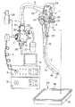
図1ないし図3は本発明の第1の実施の形態に係わり、図1は本発明の第1の実施の形態を備えた内視鏡装置の全体構成を示す全体構成図、図2は本実施の形態の内視鏡洗滌滅菌システムの概要図、図3は図2の内視鏡洗浄装置に収納された際のトレイを示す説明図であり、図3(a)は内視鏡を収容したトレイの表面図、図3(b)は同図(a)のB−B断面図である。
【0015】
図1に示すように本発明の第1の実施の形態を備えた内視鏡装置1は、図示しない撮像手段を備えた内視鏡2と、前記内視鏡2に着脱自在に接続されてこの内視鏡2に設けられたライトガイドに照明光を供給する光源装置3と、前記内視鏡2と信号ケーブル4を介して接続されて前記内視鏡2の前記撮像手段を制御すると共に、この撮像手段から得られた信号を処理して標準的な映像信号を出力するビデオプロセッサ5と、このビデオプロセッサ5からの映像信号を入力し、内視鏡画像を表示するモニタ6から構成されている。尚、前記内視鏡2は観察や処置に使用された後には、洗滌後にオートクレーブ滅菌(高温高圧蒸気滅菌)にて滅菌を行うことが可能なように構成されている。
【0016】
前記内視鏡2は可撓性を有する細長の挿入部7と、この挿入部7の基端側に設けられた操作部8、この操作部8の側部から延出した可撓性を有するユニバーサルコード9と、このユニバーサルコード9の端部に設けられた前記光源装置3と着脱自在に接続可能なコネクタ部10と、このコネクタ部10の側部に延出して前記ビデオプロセッサ5と接続可能な前記信号ケーブル4が着脱自在に接続可能な電気コネクタ部11とから主に構成される。前記電気コネクタ部11には、前記内視鏡2の内部と外部とを連通する図示しない通気部が設けられている。
【0017】
前記挿入部7と前記操作部8との接続部には、この接続部の急激な曲がりを防止する弾性部材を有する挿入部側折れ止め部材12が設けられており、同様に前記操作部8と前記ユニバーサルコード9との接続部には操作部側折れ止め部材13が設けられ、前記ユニバーサルコード9と前記コネクタ部10との接続部にはコネクタ部側折れ止め部材14が設けられている。
【0018】
前記挿入部7は可撓性を有する柔軟な軟性部である可撓管部15と、この可撓管部15の先端側に設けられた前記操作部8の操作により湾曲可能な湾曲部16と、先端に設けられ図示しない観察光学系、照明光学系などが配設された先端部17とから構成されている。
【0019】
前記操作部8には送気操作、送水操作を操作する送気送水操作ボタン21と、吸引操作を操作するための吸引操作ボタン22と、前記湾曲部16の湾曲操作を行うための湾曲操作ノブ23と、前記ビデオプロセッサ5を遠隔操作する複数のリモートスイッチ24と、前記処置具チャンネルに連通した開口である処置具挿入口25とが設けられている。
【0020】
前記先端部17には送気操作、送水操作によって図示しない観察光学系の観察窓に向けて洗滌液体や気体を噴出するための図示しない送液口及び送気送水ノズルと、前記挿入部7に配設された処置具を挿通したり体腔内の液体を吸引するための図示しない処置具チャンネルの先端側開口である図示しない吸引口とが設けられている。
【0021】
前記コネクタ部10には前記光源装置3に内蔵された図示しない気体供給源と着脱自在に接続される気体供給口金26と、液体供給源である送水タンク27と着脱自在に接続される送水タンク加圧口金28及び液体供給口金29と、前記先端部17の前記吸引口より吸引を行うための図示しない吸引源と接続される吸引口金30と、前記先端部17の前記送液口より送水を行うための図示しない送水手段と接続される注入口金31とが設けられている。また、前記コネクタ部10には、高周波処理等を行った際に内視鏡に高周波漏れ電流が発生した場合に漏れ電流を高周波処理装置に帰還させるためのアース端子口金32が設けられている。
【0022】
また、前記コネクタ部10には前記内視鏡2の形状に対応した図示しない規制部が形成されている。この規制部は前記内視鏡2のそれぞれの部分が所定の位置に納まるように形成されている。また、前記規制部には前記挿入部7が収容される図示しない挿入部規制部が設けられている。
前記電気コネクタ部11には圧力調整弁付き防水キャップ(以下、防水キャップ)33が着脱自在に接続可能であり、この防水キャップ33には図示しない圧力調整弁が設けられている。
【0023】
オートクレーブ滅菌(高温高圧蒸気滅菌)の際には、前記内視鏡2を収容する滅菌用収容ケース34を用いる。
前記収容ケース34は、内視鏡挿入部を収容する後述の収容凹部を形成した内視鏡用高温高圧蒸気滅菌容器としてのトレイ35と、このトレイ35に設けられた裏蓋部材36とから構成されている。これらトレイ35と裏蓋部材36とには複数の図示しない通気口が設けられており、オートクレーブ滅菌(高温高圧蒸気滅菌)時にはこの孔を通じて水蒸気が通過できるようになっている。
【0024】
上述したように高温高圧蒸気滅菌の代表的な条件としては米国規格ANSI/AAMI ST37−1992ではプレバキュームタイプで滅菌工程132℃で4分、グラビティタイプで滅菌工程132℃で10分とされている。
このオートクレーブ滅菌(高温高圧蒸気滅菌)の滅菌工程の温度条件については図示しないオートクレーブ滅菌装置の形式や滅菌工程の時間によって異なるが、一般的には115℃から138℃程度の範囲で設定される。滅菌装置の中には142℃程度に設定可能なものもある。時間条件については滅菌工程の温度条件によって異なるが、一般的には3分〜60分程度に設定される。滅菌装置の種類によっては100分程度に設定可能なものもある。この工程での滅菌室内の圧力は、一般的には大気圧に対して+0.2MPa程度に設定される。
【0025】
一般的なプレバキュームタイプのオートクレーブ滅菌(高温高圧蒸気滅菌)工程には、滅菌対象機器を収納した滅菌室内を滅菌工程の前に減圧状態にするプレバキューム工程と、この後に滅菌室内に高圧高温蒸気を送り込んで滅菌を行う滅菌工程とが含まれている。前者のプレバキューム工程は、後者の滅菌工程時に滅菌対象機器の細部にまで蒸気を浸透させるための工程であり、滅菌室内を減圧させることによって滅菌対象機器全体に高圧高温蒸気が行き渡るようになる。前記プレバキューム工程における滅菌室内の圧力は、一般的には大気圧に対して−0.07MPa〜0.09MPa程度に設定される。
【0026】
滅菌後の滅菌対象機器を乾燥させるために滅菌工程後に滅菌室内を再度減圧状態にする乾燥工程が含まれているものがある。この乾燥工程では、滅菌室内を減圧して滅菌室内から蒸気を排除して滅菌室内の滅菌対象機器の乾燥を促進する。この工程における滅菌室内の圧力は一般的には大気圧に対して−0.07MPa〜0.09MPa程度に設定される。
【0027】
前記内視鏡2をオートクレーブ滅菌(高温高圧蒸気滅菌)する際には、前記防水キャップ33を前記電気コネクタ部11に取り付けた状態で行う。この状態では前記防水キャップ33の図示しない圧力調整弁は閉じており、前記通気口が前記防水キャップ33にて塞がれて、前記内視鏡2の内部は外部と水密的に密閉される。
【0028】
前記プレバキューム工程を有する滅菌方法の場合には、このプレバキューム工程において滅菌室内の圧力が減少して前記内視鏡2の内部より外部の方が圧力が低くなるような圧力差が生じると、前記防水キャップ33の圧力調整弁が開き前記通気口を介して前記内視鏡2の内部と外部とが連通して前記内視鏡2の内部と滅菌室内の圧力に大きな圧力差が生じるのを防ぐ。このことにより前記内視鏡2は、内部と外部の圧力差によって破損することがない。
【0029】
前記滅菌工程においては、滅菌室内が加圧され前記内視鏡2の内部より外部の方が圧力が高くなるような圧力差が生じると前記防水キャップ33の圧力調整弁が閉じる。このことにより高圧高温の蒸気は前記防水キャップ33と前記通気口とを介しては前記内視鏡2の内部に積極的には侵入しない。
【0030】
しかしながら、高温高圧蒸気は高分子材料で形成された前記可撓管部15の外皮や前記内視鏡2の外装体の接続部に設けられたシール手段であるフッ素ゴムやシリコンゴム等から形成されたOリング等から内部に徐々に侵入する。尚、前記内視鏡2の外装体には、前記プレバキューム工程で減圧された圧力と、前記滅菌工程での加圧された圧力とが加算された外部から内部に向けた圧力が生じた状態となる。
【0031】
前記滅菌工程後に減圧工程を含む方法の場合には、この減圧工程において滅菌室の圧力が減少して前記内視鏡2の内部より外部の方が圧力が低くなるような圧力差が発生するのとほぼ同時に前記防水キャップ33の圧力調整弁が開き、前記通気口を介して前記内視鏡2の内部と外部とが連通して前記内視鏡2の内部と滅菌室内との圧力に大きな圧力差が生じるのを防ぐ。このことにより前記内視鏡2は、内部と外部との圧力差によって破損することがない。
【0032】
前記減圧工程が終わり、滅菌室内が加圧され前記内視鏡2の内部より外部の方が圧力が高くなるような圧力差が生じると前記圧力調整弁が閉じる。
上述したように高温高圧蒸気滅菌の全ての工程が終了すると、前記内視鏡2の外装体には前記減圧工程で減圧された分外部から内部に向けた圧力が生じた状態となる。
【0033】
前記防水キャップ33を電気コネクタ部11から取り出すと前記通気口により前記内視鏡2の内部と外部とが連通して前記内視鏡2の内部は大気圧となり、前記内視鏡2の外装体を生じていた圧力による負荷がなくなるようになっている。
【0034】
本実施の形態では、上述したように前記内視鏡2に対して上記オートクレーブ滅菌(高温高圧蒸気滅菌)を行うための容器である前記トレイ35を前記内視鏡2を収容した状態で、後述の内視鏡洗滌機内に収納し、前記内視鏡2を洗滌可能に構成する。
【0035】
図2は、本実施の形態の内視鏡洗滌滅菌システムの概要図を示す。
図2に示すように内視鏡洗滌機40は、洗滌機本体40aに前記トレイ35を収納可能な洗滌槽41が設けられており、この洗滌槽41に前記内視鏡2を収容した前記トレイ35を収納して密閉可能な防水蓋42が前記洗滌槽41に対向して開閉可能に設けられている。
【0036】
前記洗滌槽41内部の側壁には、この洗滌槽41内部に洗滌液や水等の液体を導入するための注水口43と、前記内視鏡2の処置具チャンネル内部を洗滌するために前記内視鏡2の処置具挿入口25に着脱自在に取り付けられる処置チャンネル洗滌具44と、前記内視鏡2の送気送水管路内部を洗滌するために前記内視鏡2の前記送気送水操作ボタン21及び吸引操作ボタン22を取り除いた後の送気・送水シリンダに着脱自在に取り付けられる送気送水洗滌具45と、前記洗滌槽41内部の洗滌液や水等の液体を排出するための排水具46とが設けられている。尚、これら以外に前記洗滌槽41内部の側壁には、内視鏡の機能に合わせて、更に別の管路等を洗滌するための洗滌具が設けられていても良い。
【0037】
前記トレイ35は、前記内視鏡2が収容された状態で前記内視鏡洗滌機40の前記洗滌槽41に収納されて、前記トレイ35内の前記内視鏡2を洗滌することができるようになっている。
【0038】
一方、上述したように前記内視鏡2をオートクレーブ滅菌(高温高圧蒸気滅菌)するためのオートクレーブ滅菌装置50は、オートクレーブ装置本体50aに前記トレイ35を収納してオートクレーブ滅菌(高温高圧蒸気滅菌)を行うチャンバ51と、このチャンバ51に対して気密的に密閉する開閉可能な開閉扉52とが設けられている。
【0039】
尚、オートクレーブ装置50には、図示しないが高温高圧蒸気用の水を貯えるための貯水タンクと、この貯水タンクの水で高温高圧蒸気を発生する蒸気発生装置と、減圧工程等で前記チャンバ51内の蒸気やその他のガスを排気するための吸引ポンプと、これらの動作を行うための複数の切替え弁と、蒸気やその他の流体の流れを制御する制御装置などが設けられている。
【0040】
前記トレイ35は、前記内視鏡2が収容された状態で前記オートクレーブ装置50の前記チャンバ51内に収納されて、前記トレイ35内の前記内視鏡2をオートクレーブ滅菌(高温高圧蒸気滅菌)することができるようになっている。尚、前記トレイ35は、オートクレーブ滅菌(高温高圧蒸気滅菌)時の高温高圧蒸気に対して耐性を有する材質で形成されている。
【0041】
図3は、前記トレイ35に前記内視鏡2を収容し、前記内視鏡洗滌機40の前記洗滌槽41に前記トレイ35を収納した様子を示している。
図3(a)に示すように前記トレイ35には、前記内視鏡2を収容するための収容凹部である内視鏡収容部61が形成されていて、この内視鏡収容部61の底面及び側面はほぼ平滑な面となっている。前記内視鏡2を前記内視鏡収容部61に多少のクリアランスで収容すると、収容された前記内視鏡操作部8は大きくスライドすることは無く、また、前記ユニバーサルコード9や前記可撓管部15は自ずと収容形態(曲げ形状)が決まるようになっている。尚、図3(a)中斜線部は前記内視鏡収容部61に対して突出する凸部35aである。また、前記可撓管部15、ユニバーサルコード9、操作部8及びコネクタ部10の高さ(幅)も低い(薄い)ので、これらを前記内視鏡収容部61に収容しても、前記斜線部よりは十分に低くなるようになっている。
【0042】
前記内視鏡収容部61は、前記内視鏡挿入部7の可撓管部15を丸めて配置するようになっている。これは、前記内視鏡2には、前記可撓管部15が短いものから長いものまであるが、可撓管部15が長い機種では前記内視鏡2を配置するのに比較的小型のオートクレーブ滅菌装置50に入らなくなるためである。
【0043】
また、このとき、前記内視鏡挿入部7の前記可撓管部15は軟性樹脂で形成されているので、丸めて収容配置し、オートクレーブ装置50でオートクレーブ滅菌(高温高圧蒸気滅菌)を行うと、前記可撓管部15に多少の曲がり癖が付く虞れがある。このため、前記内視鏡挿入部7の前記可撓管部15に多少の曲がり癖が付いたとしても、挿入性など検査に極力支障が出ないように、前記内視鏡収容部61は前記可撓管部15の矢印A部分から内視鏡挿入部7の先端部17まで略ストレート状に配置されるように形成している。
【0044】
尚、下部消化管用内視鏡の場合、挿入部は例えば133cmや168cmあるが、一般的に大腸の肛門から盲腸部まで極力余分な撓みを除くように挿入されると、約70cmまでが挿入されることになると言われており、この70cmまでは殆ど全ての患者に対して挿入される重要な部分である。従って、本実施の形態では、この70cmまでの部分を前記可撓管部15の矢印A部分として、略ストレート状に収容し、曲がり癖などが付くのを防ぐようにしている。
【0045】
また、前記内視鏡2の前記コネクタ部10が収容される付近には、前記内視鏡2から外した送気送水操作ボタン21、吸引操作ボタン22や検査時に処置具挿入口25に取り付ける処置具栓25aなどの小物が収容されるようになっている。尚、これら小物は前記内視鏡2と共に前記内視鏡収容部61に収容配置されずとも、オートクレーブ滅菌(高温高圧蒸気滅菌)及び洗滌が可能であれば、前記内視鏡収容部61とは別に前記トレイ35に収容部を設けても良い。また、前記トレイ35には、鉗子等の処置具を収容し、前記内視鏡2と共にオートクレーブ滅菌(高温高圧蒸気滅菌)及び洗滌を行うことができるように構成しても構わない。
【0046】
また、前記内視鏡収容部61の操作部付近61bは、前記内視鏡操作部8の前記処置具挿入口25開口部や前記送気送水操作ボタン21及び吸引操作ボタン22を取り除いた後の送気・送水シリンダ開口部が水平方向よりも斜め上を向くように、図3(b)に示すように前記凸部35aに対して斜め形状に形成されている。これにより、操作部8の処置具挿入口25開口部や送気・送水シリンダ開口部は、重力方向(鉛直下向き方向)やこの重力方向(鉛直下向き方向)に対して水平方向よりも斜め上を向くように収容配置される。
【0047】
従来では、内視鏡2の各管路両端をどういう向きでオートクレーブ装置50内に収容しているか考慮されていない。もし、オートクレーブ滅菌可能な内視鏡2をプレバキューム工程なしでオートクレーブ滅菌を行う場合、内視鏡2の各管路の開口が全て重量方向を向いていると、蒸気が十分管路内に行き渡らない可能性がある。
【0048】
しかしながら、本実施の形態では、操作部8の処置具挿入口25開口部や送気・送水シリンダ開口部が重力方向(鉛直下向き方向)やこの重力方向(鉛直下向き方向)に対して水平方向よりも斜め上を向くようになっているので、蒸気が重力によって内視鏡2の管路内に入り易く十分行き渡るようになっている。また、これらチャンネルの他端の開口部は、例えば前記先端部17に設けられているが、これも同様な理由で開口部が重力方向(鉛直下向き方向)やこの重力方向(鉛直下向き方向)に対して水平方向よりも斜め上を向くように収容配置される。このことにより、本実施の形態では、オートクレーブ滅菌でプレバキューム無しの工程においても、内視鏡2の管路内に十分蒸気が行き渡るように構成される。
【0049】
また、前記トレイ35の一部には、取っ手62が設けられ、前記トレイ35を運搬し易いようになっている。そして、前記トレイ35が洗滌槽41に収容されているときは、前記処置チャンネル洗滌具排水具46を前記内視鏡2の処置具挿入口25に接続し、前記送気送水洗滌具46を前記送気送水操作ボタン21及び吸引操作ボタン22を取り除いた後の送気・送水シリンダに接続するようになっている。また、前記排水具46先端は、前記内視鏡収容部61の凹状部底面に置くようになっている。
【0050】
このように構成された内視鏡洗滌滅菌システムの作用を説明する。
内視鏡検査終了後、内視鏡2を洗滌する際に、内視鏡2及びこの内視鏡2から取り外した部材等をトレイ35に収容しておくことで、後はトレイ35を内視鏡洗滌機40の洗滌槽41にセットして洗滌すると共に、洗滌後、トレイ35を内視鏡洗滌機40の洗滌槽41から取り出して、この状態のままでトレイ35をオートクレーブ装置50のチャンバ51内に収納して、オートクレーブ滅菌(高温高圧蒸気滅菌)を行うようにすれば良い。これにより、オートクレーブ前に洗滌後の内視鏡2及びこの内視鏡2から取り外した部材等を改めてトレイやコンテナにセットする手間が省ける。
【0051】
ユーザは、内視鏡検査終了後、内視鏡2及びこの内視鏡2から取り外した部材等をトレイ35の内視鏡収容部61の所定の場所に収容し、このトレイ35を内視鏡洗滌機40の洗滌槽41に収納する。そして、ユーザは、内視鏡2の送気送水操作ボタン21及び吸引操作ボタン22を取り除いた後の送気・送水シリンダに送気送水洗滌具45を取り付けると共に、内視鏡2の処置具挿入口25に処置チャンネル洗滌具44を取り付け、排水具46を洗滌槽41の内視鏡収容部61の所定の場所に配置する。そして、ユーザは、防水蓋42を閉め、内視鏡洗滌機40を稼動し、洗滌を行う。洗滌終了後、ユーザは、内視鏡洗滌機40からトレイ35を取り出す。この後は、このトレイ35に蓋部材36をかぶせても良いし、ピールパックなどで覆っても良い。
【0052】
そして、ユーザは、内視鏡2及びこの内視鏡2から取り外した部材等を収容したこのままの状態でトレイ35をオートクレーブ装置50内のチャンバ51に収納し、オートクレーブ滅菌(高温高圧蒸気滅菌)を行う。
このとき、内視鏡挿入部2の可撓管部15は所定形状でトレイ35に収容された状態でオートクレーブ滅菌がなされるので、仮に可撓管部15の曲げている所定部分に曲がり癖が多少付いたとしても、可撓管部15先端側の挿入性に影響が大きい主要部分は略ストレートに保れているので挿入性への悪影響は無い。
【0053】
また、オートクレーブ装置50は、場合によってはプレバキューム工程の無い装置、又はプレバキューム工程を行うことができても、ユーザがプレバキューム工程を行わないよう設定した場合、蒸気が重力によってチャンバ51内に満たされる。
【0054】
このとき、上述したように内視鏡操作部8の処置具挿入口25開口部や送気・送水シリンダ開口部は重力方向(鉛直下向き方向)やこの重力方向(鉛直下向き方向)に対して水平方向よりも斜め上を向いているので、重力により蒸気が内視鏡2の管路内に入り易い。また、これらチャンネルの先端部17に設けられている他端の開口部は、重力方向(鉛直下向き方向)やこの重力方向(鉛直下向き方向)に対して水平方向よりも斜め上を向いているので、蒸気は十分行き渡る。
【0055】
トレイ35はユーザにとって上方向が明らかなので、このトレイ35の取っ手62を持ってトレイ35をそのままチャンバ51内に移動させれば、処置具挿入口25開口や送気送水シリンダの開口は自然とオートクレーブ装置50内のチャンバ51で重力方向(鉛直下向き方向)やこの重力方向(鉛直下向き方向)に対して水平方向よりも斜め上を向くことになる。
【0056】
尚、トレイ35を用いずに内視鏡2及びこの内視鏡2から取り外した部材等をオートクレーブ装置50内のチャンバ51に直接収納する場合、内視鏡操作部8の処置具挿入口25開口部や送気送水シリンダ、又はこれらチャンネルの先端部17に設けられている他端の開口部等、内視鏡2に設けられている各管路の少なくとも一方の開口部が水平方向より僅かでも重力方向(鉛直下向き方向)やこの重力方向(鉛直下向き方向)に対して水平方向よりも斜め上を向くように、内視鏡2を設置する設置器具をチャンバ51内に設けても良い。
【0057】
この結果、本実施の形態の内視鏡洗滌滅菌システムは、内視鏡2を内視鏡洗滌機40からオートクレーブ装置50に移すときに所定形状にセットし直す手間が省ける。
【0058】
(第2の実施の形態)
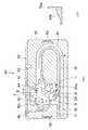
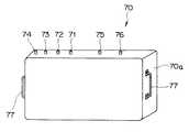
図4及び図5は本発明の第2の実施の形態に係わり、図4は本発明の第2の実施の形態の滅菌コンテナを示す外観図、図5は図4の滅菌コンテナ内部を示す説明図である。
上記第1の実施の形態では、内視鏡用高温高圧蒸気滅菌容器として内視鏡収容部61を設けたトレイ35を用いて内視鏡洗滌滅菌システムを構成しているが、本第2の実施の形態では、内視鏡用高温高圧蒸気滅菌容器として滅菌コンテナを用いて内視鏡洗滌滅菌システムを構成する。それ以外の構成は、上記第1の実施の形態と同様なので説明を省略し、同じ構成には同じ符号を付して説明する。
【0059】
図4に示すように内視鏡用高温高圧蒸気滅菌容器としての滅菌コンテナ70は、蓋で密閉され、蒸気は侵入可能であるが、液体は侵入できないように構成されている。このため、前記滅菌コンテナ70は、オートクレーブ滅菌後、このままの密閉状態で滅菌保持できるようになっている。尚、前記滅菌コンテナ70は、オートクレーブ滅菌(高温高圧蒸気滅菌)時の高温高圧蒸気に対して耐性を有する材質で形成されている。
【0060】
図5に示すように前記滅菌コンテナ70の内部は、上記第1の実施の形態で説明したのと同様な内視鏡収容部61を設けており、この内視鏡収容部61に内視鏡2及びこの内視鏡2から取り外した部材等を収容するようになっている。
前記滅菌コンテナ70は、上記第1の実施の形態で説明した内視鏡洗滌装置40の注水口43、処置チャンネル洗滌具44、送気送水洗滌具45及び排水具46に相当する口金に着脱自在に接続可能な注水口金71、処置チャンネル洗滌口金72、送気送水洗滌口金73及び排水口金74がコンテナ本体70aの外部に対して設けられている。これら口金の他端は、前記滅菌コンテナ70内部でそれぞれ上記第1の実施の形態で説明した内視鏡洗滌装置40の注水口43、処置チャンネル洗滌具44、送気送水洗滌具45及び排水具46と同様な形状となっている。尚、これら以外に前記滅菌コンテナ70内部には、内視鏡の機能に合わせて、更に別の管路等を洗滌するための洗滌具が設けられていても良い。
【0061】
また、滅菌コンテナ70は、オートクレーブ装置50に設けられている図示しない蒸気注入用口金及び蒸気排気用口金に着脱自在に接続可能な蒸気注入口金75及び蒸気蒸気排気口金76がコンテナ本体70aの外部に対して設けられている。これら蒸気注入口金75及び蒸気蒸気排気口金76の他端は、それぞれ蒸気注入用及び蒸気排気用に適した形状となっている。また、前記滅菌コンテナ70は、このコンテナ本体70a側部に取っ手77が設けられ、運搬し易いようになっている。
【0062】
前記滅菌コンテナ70は、前記内視鏡洗滌装置40の洗滌槽41に押し込み収容すると、前記内視鏡洗滌装置40の注水口43、処置チャンネル洗滌具44、送気送水洗滌具45及び排水具46に相当する口金に前記注水口金71、処置チャンネル洗滌口金72、送気送水洗滌口金73及び排水口金74が簡単に(自然に)それぞれと接続されるようになっている。
【0063】
一方、前記滅菌コンテナ70は、前記オートクレーブ装置50内のチャンバ51に押し込み収容すると、前記オートクレーブ装置50の蒸気注入用口金及び蒸気排気用口金に簡単に(自然に)蒸気注入口金75、蒸気排気口金76が接続されるようになっている。即ち、滅菌コンテナ70は、これ自体で内視鏡洗滌機40における洗滌槽41の機能を有し、オートクレーブ装置50におけるチャンバ51の機能も有している。もちろん、滅菌コンテナ70は、洗滌、オートクレーブ滅菌を行っている間に、この滅菌コンテナ70の密閉状態が壊れることがないようにロックされている。
【0064】
これにより、滅菌コンテナ70は、この滅菌コンテナ70に内視鏡2及びこの内視鏡2から取り外した部材等を収容後、開けることなく、洗滌、滅菌を行い、その後は滅菌保持したまま保管できる。また、滅菌コンテナ70は、オートクレーブ装置50において、滅菌コンテナ70自体がチャンバ51となるので、内視鏡2及びこの内視鏡2から取り外した部材等を滅菌するのに必要最低限の蒸気量で稼動できるので、一連の滅菌サイクルを短くできる。
【0065】
この結果、本第2の実施の形態の内視鏡洗滌滅菌システムは、上記第1の実施の形態と比べて、更に、ユーザの手間が省ける。
【0066】
尚、本発明は、以上述べた実施形態のみに限定されるものではなく、発明の要旨を逸脱しない範囲で種々変形実施可能である。
【0067】
ところで、一般に、滅菌後、内視鏡2は検査直前までハンガに掛けられて待機されることが多く、この滅菌後の内視鏡2をハンガにかけると、このハンガによる汚染の可能性もある。従来は、オートクレーブ滅菌可能な内視鏡と共に、ハンガをオートクレーブ滅菌することがない。
そこで、滅菌後の内視鏡が検査直前待機中に、ハンガによる汚染がないように内視鏡2を掛けるハンガも内視鏡2と共にオートクレーブ滅菌できるように構成する。
【0068】
図6は、トロリに設けられたハンガ装置を説明する説明図である。
図6に示すようにトロリ80は、ビデオプロセッサ5やモニタ6等内視鏡画像を構築するのに必要な機材が納められている。このトロリ80の一部には、前記内視鏡2を検査直前待機でぶら下げておくハンガ90が取り付けられるようになっている。
【0069】
前記ハンガ90は、ヘッド部91と基部92とから構成されている。前記ヘッド部91は、接続部93と内視鏡取付部94とから構成される。そして、前記ヘッド部91は、前記接続部93において前記基部92に対して着脱自在であると共に、オートクレーブ滅菌耐性を有している。
【0070】
このように構成されたハンガ90は、内視鏡検査後、内視鏡2と共に、内視鏡取付部94を基部92から分離し、洗滌、オートクレーブ滅菌を行い、滅菌後は内視鏡取付部94を内視鏡2に取り付けた状態で基部92に接続する。
【0071】
そして、内視鏡検査では、内視鏡2を内視鏡取付部94から離して用いる。こうすることで、内視鏡検査まで、内視鏡2(操作部8や挿入部7)はオートクレーブ滅菌されていない部材に触れることがない。
【0072】
この結果、内視鏡2を掛けるハンガ90も内視鏡2と共にオートクレーブ滅菌できるようにすることで、検査直前まで待機中に内視鏡2が汚染される虞れがない。
【0073】
[付記]
(付記項1) 内視鏡を収容して高温高圧蒸気滅菌するための容器であって、前記内視鏡を収容した状態で、洗滌可能に洗滌機内に収納することを特徴とする内視鏡用高温高圧蒸気滅菌容器。
【0074】
(付記項2) 内視鏡を収容して高温高圧蒸気滅菌するための容器と、
前記内視鏡が収容された状態で前記容器を収納し、この容器内の内視鏡を洗滌する洗滌機と、
を具備することを特徴とする内視鏡洗滌滅菌システム。
【0075】
(付記項3) 前記容器は、高温高圧蒸気に対して耐性を有する材質で形成していることを特徴とする付記項1に記載の内視鏡用高温高圧蒸気滅菌容器。
【0076】
(付記項4) 前記容器は、前記内視鏡を密閉可能なコンテナであることを特徴とする付記項1に記載の内視鏡用高温高圧蒸気滅菌容器。
【0077】
(付記項5) 前記容器は、運搬用の取っ手を設けていることを特徴とする付記項1に記載の内視鏡用高温高圧蒸気滅菌容器。
【0078】
(付記項6) 内視鏡を吊り下げるハンガ装置において、
ハンガ基部に対して着脱自在で、高温高圧蒸気滅菌可能なハンガヘッド部を有することを特徴とするハンガ装置。
【0079】
(付記項7) 前記ハンガヘッドは、高温高圧蒸気滅菌可能な内視鏡と組み合わせた状態でハンガ基部に着脱可能であることを特徴とする付記項9に記載のハンガ装置。
【0080】
(付記項8) 細長で軟性の挿入部及びこの挿入部に挿通する管路を有する高温高圧蒸気滅菌可能な内視鏡を、前記管路開口の少なくとも一方を重力方向以外の方向に向けて、高温高圧蒸気滅菌装置に収納する手段を設けたことを特徴とする内視鏡高温高圧蒸気滅菌システム。
【0081】
(付記項9) 前記高温高圧蒸気滅菌可能な内視鏡を収納する手段は、内視鏡用収納容器であることを特徴とする付記項8に記載の内視鏡高温高圧蒸気滅菌システム。
【0082】
【発明の効果】
以上説明したように本発明によれば、内視鏡を洗滌機による洗滌、オートクレーブ装置による高温高圧蒸気滅菌にかける場合に、極力簡単にできる。
【図面の簡単な説明】
【図1】本発明の第1の実施の形態を備えた内視鏡装置の全体構成を示す全体構成図
【図2】本実施の形態の内視鏡洗滌滅菌システムの概要図
【図3】図2の内視鏡洗浄装置に収納された際のトレイを示す説明図
【図4】本発明の第2の実施の形態に係る滅菌コンテナを示す外観図
【図5】図4の滅菌コンテナ内部を示す説明図
【図6】トロリに設けられたハンガを説明する説明図
【符号の説明】
1 …内視鏡装置
2 …内視鏡
7 …挿入部
15 …可撓管部
21 …送気送水操作ボタン
22 …吸引操作ボタン
25 …処置具挿入口
35 …トレイ(内視鏡用高温高圧蒸気滅菌容器)
40 …内視鏡洗滌機
41 …洗滌槽
50 …オートクレーブ滅菌装置
51 …チャンバ
61 …内視鏡収納部[0001]
BACKGROUND OF THE INVENTION
The present invention relates to an endoscope high-temperature and high-pressure steam sterilization container and an endoscope cleaning and sterilization system that enable autoclave sterilization (high-temperature and high-pressure steam sterilization) without hindrance.
[0002]
[Prior art]
Today, endoscopes are widely used in the medical field. The endoscope can perform a therapeutic treatment or the like by observing a deep portion or the like in the body cavity by inserting an elongated insertion portion into the body cavity or the like, or using a treatment tool as necessary. It is essential that these medical endoscopes are sterilized and sterilized after use.
[0003]
Recently, autoclave sterilization (high-temperature high-pressure steam sterilization) is becoming mainstream as sterilization of endoscope devices. The autoclave sterilization (high-temperature and high-pressure steam sterilization) does not involve complicated work, can be used immediately after sterilization, and the running cost is low.
[0004]
Such autoclave sterilization (high-temperature and high-pressure steam sterilization) is performed by, for example, inserting an endoscope capable of high-temperature and high-pressure steam sterilization into an autoclave sterilization (high-temperature and high-pressure steam sterilization) apparatus as described in JP-A-5-285103. Then, what performs autoclave sterilization (high-temperature high-pressure steam sterilization) has been proposed.
[0005]
As typical conditions for autoclave sterilization, there is American Standard ANSI / AAMI ST37-1992 approved by the American Standards Association and issued by the Medical Device Development Association. This condition is sterilization process at 132 ° C for 4 minutes for prevacuum type, and gravity type. In the sterilization process, the temperature is 132 ° C. and 10 minutes.
[0006]
The environmental conditions of the above autoclave sterilization are extremely severe for an electronic endoscope which is a precision electronic device equipped with an imaging device such as a CCD, and autoclave sterilization (high temperature and high pressure steam sterilization) that can withstand this is possible. In order to realize an electronic endoscope, various measures such as high pressure measures, high temperature measures, and steam measures must be taken compared to endoscopes that can only be used with other disinfection / sterilization means. In particular, since the endoscope insertion part is a part that is inserted into the patient's body, various delicate characteristics such as flexibility and elasticity are required. There is a tendency to weaken (characteristics are likely to deteriorate), and more advanced measures are required.
[0007]
In autoclave sterilization (high-temperature high-pressure steam sterilization), not only the endoscope, but also various buttons such as air and water removed from the endoscope, waterproof caps attached to the endoscope, and forceps The ingredients are also placed in a tray and placed in an autoclave sterilizer.
At this time, if the peripheral parts of the endoscope described above, for example, a treatment instrument such as forceps, overlaps with or remains in contact with a soft part such as an endoscope insertion part or a universal cord, autoclave sterilization (high-temperature high-pressure steam sterilization) is performed. There is also a possibility that the endoscope insertion portion is damaged by being contact-pressed by the treatment instrument.
[0008]
As described above, not only the configuration of the endoscope insertion section itself, but also the manner of insertion when it is put into the autoclave sterilizer, so that the endoscope insertion section is not damaged due to the surroundings of the endoscope. It is also important.
[0009]
[Problems to be solved by the invention]
However, in the conventional autoclave sterilization (high-temperature and high-pressure steam sterilization), an endoscope having a slender and flexible insertion part is put into an autoclave sterilization (high-temperature and high-pressure steam sterilization) device large enough to be placed in an endoscopy room. When doing so, it is necessary to round the insertion part and insert it.
[0010]
As described above, in the conventional autoclave sterilization (high-temperature high-pressure steam sterilization), if the endoscope is thrown in a too small state, the flexible insertion portion may be damaged (for example, the influence of bending deformation due to heat may occur). For this reason, it is important to store the endoscope in a tray or container in a predetermined shape.
[0011]
In general, before the endoscope is subjected to autoclave sterilization (high-temperature and high-pressure steam sterilization), when the necessary washing is performed by an automatic washing machine, the endoscope must be stored in the washing machine in a predetermined form. That is, the user stores the endoscope in the washing machine in a predetermined form and cleans it, then takes out the endoscope and stores it in the autoclave sterilization (high-temperature and high-pressure steam sterilization) tray (or container) in the predetermined form. It was necessary and complicated.
[0012]
The present invention has been made in view of these circumstances, and when the endoscope is subjected to washing with a washing machine and high-temperature and high-pressure steam sterilization with an autoclave device, a simple high-temperature and high-pressure steam sterilization container for an endoscope and An object is to provide an endoscope cleaning and sterilization system.
[0013]
[Means for Solving the Problems]
Of the present inventionFirstEndoscopic high-temperature high-pressure steam sterilization containerFor the lower gastrointestinal tractA container for storing an endoscope and sterilizing at high temperature and high pressure steam, wherein the insertion portion of the endoscope isPart including at least 70cm from the tipIs provided in a washing machine so as to be washable in a state in which the endoscope is accommodated.
In addition, the present inventionFirstEndoscope cleaning sterilization systemFor the lower gastrointestinal tractOf the insertion part of the endoscopePart including at least 70cm from the tipA container for defining the accommodation form in a substantially straight shape, a container for housing the endoscope and sterilizing at high temperature and high pressure steam, and housing the container in a state in which the endoscope is housed, And a washing machine for washing the endoscope in the container.
With this configuration, when the endoscope is subjected to washing with a washing machine and high-temperature high-pressure steam sterilization with an autoclave device, an endoscope high-temperature high-pressure steam sterilization container and an endoscope washing and sterilization system that are as simple as possible are realized.
The second endoscope high-temperature / high-pressure steam sterilization container according to the present invention is a container for accommodating an endoscope and sterilizing at high temperature / high-pressure steam, and includes a distal end portion from the middle of the insertion portion of the endoscope. Is provided in the washing machine so that it can be washed in a state where the endoscope is housed, and the housing part is disposed in the operation part of the endoscope. In order to accommodate the pipe opening that is at least obliquely upward with respect to the horizontal direction, the vicinity of the operation portion is formed in an oblique shape.
The second endoscope cleaning and sterilization system according to the present invention further includes a storage portion that defines a storage form in a substantially straight shape from the middle of the insertion portion of the endoscope, and stores the endoscope. A container for high-temperature high-pressure steam sterilization, a container for storing the container in a state in which the endoscope is stored, and a washing machine for cleaning the endoscope in the container. In order to accommodate the duct opening provided in the operation portion of the endoscope so as to face at least obliquely upward with respect to the horizontal direction, the vicinity of the operation portion is formed in an oblique shape.
[0014]
DETAILED DESCRIPTION OF THE INVENTION
Hereinafter, embodiments of the present invention will be described with reference to the drawings.
(First embodiment)
FIGS. 1 to 3 relate to a first embodiment of the present invention, FIG. 1 is an overall configuration diagram showing an overall configuration of an endoscope apparatus including the first embodiment of the present invention, and FIG. FIG. 3 is a schematic diagram of the endoscope cleaning and sterilization system according to the embodiment, FIG. 3 is an explanatory view showing a tray when stored in the endoscope cleaning apparatus of FIG. 2, and FIG. FIG. 3B is a cross-sectional view taken along the line BB of FIG.
[0015]
As shown in FIG. 1, an
[0016]
The
[0017]
The connecting portion between the
[0018]
The
[0019]
The
[0020]
A liquid supply port and an air / water supply nozzle (not shown) for ejecting a cleaning liquid and a gas toward an observation window of an observation optical system (not shown) by the air supply operation and the water supply operation are provided at the
[0021]
The
[0022]
The
A waterproof cap (hereinafter referred to as a waterproof cap) 33 with a pressure adjusting valve can be detachably connected to the
[0023]
In autoclave sterilization (high-temperature high-pressure steam sterilization), a
The
[0024]
As described above, typical conditions for high-temperature and high-pressure steam sterilization are as follows: US standard ANSI / AAMI ST37-1992, pre-vacuum type sterilization process at 132 ° C. for 4 minutes, gravity type sterilization process at 132 ° C. for 10 minutes. .
The temperature conditions in the sterilization process of autoclave sterilization (high-temperature and high-pressure steam sterilization) vary depending on the type of an autoclave sterilizer (not shown) and the time of the sterilization process, but are generally set in the range of about 115 ° C to 138 ° C. Some sterilizers can be set to about 142 ° C. About time conditions, although it changes with temperature conditions of a sterilization process, it is generally set to about 3 to 60 minutes. Some types of sterilizers can be set to about 100 minutes. The pressure in the sterilization chamber in this step is generally set to about +0.2 MPa with respect to atmospheric pressure.
[0025]
The general pre-vacuum type autoclave sterilization (high-temperature high-pressure steam sterilization) process includes a pre-vacuum process in which the sterilization chamber containing the equipment to be sterilized is depressurized before the sterilization process, and then a high-pressure high-temperature steam in the sterilization chamber. And a sterilization step of performing sterilization. The former pre-vacuum process is a process for infiltrating steam into the details of the sterilization target device during the latter sterilization process, and high pressure and high temperature steam is distributed throughout the sterilization target device by reducing the pressure in the sterilization chamber. The pressure in the sterilization chamber in the pre-vacuum process is generally set to about -0.07 MPa to 0.09 MPa with respect to atmospheric pressure.
[0026]
Some include a drying step in which the inside of the sterilization chamber is decompressed again after the sterilization step in order to dry the sterilization target device after sterilization. In this drying step, the interior of the sterilization chamber is depressurized to remove steam from the sterilization chamber and promote drying of the sterilization target device in the sterilization chamber. The pressure in the sterilization chamber in this step is generally set to about -0.07 MPa to 0.09 MPa with respect to atmospheric pressure.
[0027]
When the
[0028]
In the case of the sterilization method having the pre-vacuum process, when a pressure difference is generated such that the pressure in the sterilization chamber decreases in the pre-vacuum process and the pressure is lower outside the
[0029]
In the sterilization process, when a pressure difference is generated such that the inside of the sterilization chamber is pressurized and the pressure is higher outside the
[0030]
However, the high-temperature and high-pressure steam is formed from fluoro rubber, silicon rubber, or the like, which is a sealing means provided at the outer skin of the
[0031]
In the case of a method including a decompression step after the sterilization step, a pressure difference is generated such that the pressure in the sterilization chamber decreases and the pressure outside the
[0032]
When the depressurization step is completed and the pressure inside the sterilization chamber is increased and a pressure difference is generated such that the pressure is higher in the outside than in the
As described above, when all the processes of high-temperature and high-pressure steam sterilization are completed, the exterior body of the
[0033]
When the
[0034]
In the present embodiment, as described above, the
[0035]
FIG. 2 shows a schematic diagram of the endoscope cleaning and sterilization system of the present embodiment.
As shown in FIG. 2, the
[0036]
On the side wall inside the
[0037]
The
[0038]
On the other hand, as described above, the
[0039]
Although not shown, the
[0040]
The
[0041]
FIG. 3 shows a state in which the
As shown in FIG. 3A, the
[0042]
The
[0043]
At this time, since the
[0044]
In the case of the endoscope for the lower digestive tract, the insertion portion is, for example, 133 cm or 168 cm. Generally, when the insertion portion is inserted from the large anus to the cecum portion so as to remove as much as possible, up to about 70 cm is inserted. This 70 cm is an important part that is inserted for almost all patients. Therefore, in the present embodiment, the portion up to 70 cm is accommodated in a substantially straight shape as the arrow A portion of the
[0045]
In addition, in the vicinity of the
[0046]
Further, the
[0047]
Conventionally, it is not considered in what direction the both ends of each pipeline of the
[0048]
However, in the present embodiment, the treatment
[0049]
Further, a
[0050]
The operation of the endoscope cleaning and sterilization system configured as described above will be described.
When the
[0051]
After the end of the endoscopy, the user accommodates the
[0052]
Then, the user stores the
At this time, since the
[0053]
In addition, the
[0054]
At this time, as described above, the treatment
[0055]
Since the
[0056]
When the
[0057]
As a result, the endoscope cleaning and sterilization system according to the present embodiment saves the trouble of resetting the
[0058]
(Second Embodiment)
4 and 5 relate to the second embodiment of the present invention, FIG. 4 is an external view showing the sterilization container of the second embodiment of the present invention, and FIG. 5 is an explanation showing the inside of the sterilization container of FIG. FIG.
In the first embodiment, the endoscope cleaning and sterilization system is configured by using the
[0059]
As shown in FIG. 4, a
[0060]
As shown in FIG. 5, the inside of the
The
[0061]
In the
[0062]
When the
[0063]
On the other hand, when the
[0064]
As a result, the
[0065]
As a result, the endoscope cleaning and sterilization system according to the second embodiment can further save the user's effort compared to the first embodiment.
[0066]
The present invention is not limited to the above-described embodiments, and various modifications can be made without departing from the spirit of the invention.
[0067]
By the way, in general, after sterilization, the
Therefore, the hanger on which the
[0068]
FIG. 6 is an explanatory view for explaining a hanger device provided in the trolley.
As shown in FIG. 6, the
[0069]
The
[0070]
The
[0071]
In the endoscopy, the
[0072]
As a result, the
[0073]
[Appendix]
(Additional Item 1) A container for storing an endoscope and sterilizing at high temperature and high pressure steam, and storing the endoscope in a washing machine so that the endoscope can be cleaned. High temperature high pressure steam sterilization container.
[0074]
(Additional Item 2) A container for accommodating an endoscope and sterilizing at high temperature and high pressure steam,
A washing machine for storing the container in a state in which the endoscope is accommodated, and washing the endoscope in the container;
An endoscope cleaning and sterilization system comprising:
[0075]
(Additional Item 3) The high-temperature and high-pressure steam sterilization container for endoscope according to
[0076]
(Additional Item 4) The high-temperature and high-pressure steam sterilization container for an endoscope according to
[0077]
(Additional Item 5) The high-temperature and high-pressure steam sterilization container for an endoscope according to
[0078]
(Additional Item 6) In the hanger device that hangs the endoscope,
A hanger device comprising a hanger head portion that is detachable from a hanger base and capable of high-temperature and high-pressure steam sterilization.
[0079]
(Additional Item 7) The hanger device according to
[0080]
(Additional Item 8) An endoscope capable of high-temperature and high-pressure steam sterilization having an elongated and flexible insertion portion and a pipe line that passes through the insertion section, with at least one of the pipe openings directed in a direction other than the gravity direction, An endoscope high-temperature and high-pressure steam sterilization system, characterized in that a means for storing in a high-temperature and high-pressure steam sterilizer is provided.
[0081]
(Additional Item 9) The endoscope high-temperature and high-pressure steam sterilization system according to
[0082]
【The invention's effect】
As described above, according to the present invention, when the endoscope is subjected to washing with a washing machine and high-temperature high-pressure steam sterilization with an autoclave device, it can be simplified as much as possible.
[Brief description of the drawings]
FIG. 1 is an overall configuration diagram showing an overall configuration of an endoscope apparatus provided with a first embodiment of the present invention.
FIG. 2 is a schematic diagram of an endoscope cleaning and sterilization system according to the present embodiment.
3 is an explanatory view showing a tray when housed in the endoscope cleaning apparatus of FIG. 2; FIG.
FIG. 4 is an external view showing a sterilization container according to a second embodiment of the present invention.
FIG. 5 is an explanatory view showing the inside of the sterilization container of FIG.
FIG. 6 is an explanatory diagram for explaining a hanger provided on the trolley.
[Explanation of symbols]
1 ... Endoscopic device
2 ... Endoscope
7 ... Insertion part
15: Flexible tube
21 ... Air / water operation buttons
22 ... Suction operation button
25 ... treatment instrument insertion port
35 ... Tray (high temperature and high pressure steam sterilization container for endoscope)
40: Endoscope washing machine
41 ... washing tank
50 ... Autoclave sterilizer
51 ... chamber
61: Endoscope storage
Claims (4)
Translated fromJapanese前記内視鏡の挿入部の少なくとも先端から70cmを含む部分を略ストレート状に収容形態を規定する収容部を備え、該内視鏡を収容した状態で、洗滌可能に洗滌機内に収納する
ことを特徴とする内視鏡用高温高圧蒸気滅菌容器。A container for storing an endoscopefor the lower digestive tract and sterilizing at high temperature and high pressure steam,
Including an accommodating portion for defining an accommodating form in a substantially straight shapeat least a portion including 70 cm from the distal end of the insertion portion of the endoscope, and storing the endoscope in the washing machine in a state where the endoscope is accommodated. A high-temperature, high-pressure steam sterilization container for endoscopes.
前記内視鏡が収容された状態で前記容器を収納し、この容器内の内視鏡を洗滌する洗滌機と、
を具備することを特徴とする内視鏡洗滌滅菌システム。A container for accommodatinga part including at least 70 cm from the distal end of the insertion part of the endoscopefor the lower digestive tract in a substantially straight shape and accommodating the endoscope for high-temperature and high-pressure steam sterilization When,
A washing machine for storing the container in a state in which the endoscope is accommodated, and washing the endoscope in the container;
An endoscope cleaning and sterilization system comprising:
前記内視鏡の挿入部の中途から先端部分を略ストレート状に収容形態を規定する収容部を備え、該内視鏡を収容した状態で、洗滌可能に洗滌機内に収納し、
前記収容部は、前記内視鏡の操作部に配設される管路開口部を水平方向よりも少なくとも斜め上方を向くように収容するために操作部付近が斜め形状に形成されている
ことを特徴とする請求項1に記載の内視鏡用高温高圧蒸気滅菌容器。A container for storing an endoscope and sterilizing at high temperature and high pressure steam,
A storage section that prescribes the storage form in a substantially straight shape from the middle of the insertion section of the endoscope, and in the state of storing the endoscope, is stored in a washing machine so that it can be cleaned,
The accommodating portion is formed in an oblique shape in the vicinity of the operation portion in order to accommodate the duct opening disposed in the operation portion of the endoscope so as to face at least obliquely above the horizontal direction. The high-temperature high-pressure steam sterilization container for endoscope according to claim 1,
前記内視鏡が収容された状態で前記容器を収納し、この容器内の内視鏡を洗滌する洗滌機と、
を具備し、
前記収容部は、前記内視鏡の操作部に配設される管路開口部を水平方向よりも少なくとも斜め上方を向くように収容するために操作部付近が斜め形状に形成されている
ことを特徴とする請求項2に記載の内視鏡洗滌滅菌システム。A container for housing the endoscope and sterilizing at a high temperature and high pressure steam, with a housing part that defines the housing form in a substantially straight shape from the middle of the insertion part of the endoscope,
A washing machine for storing the container in a state in which the endoscope is accommodated, and washing the endoscope in the container;
Comprising
The accommodating portion is formed in an oblique shape in the vicinity of the operation portion in order to accommodate the duct opening disposed in the operation portion of the endoscope so as to face at least obliquely above the horizontal direction. The endoscope cleaning and sterilizing system according to claim 2,
Priority Applications (5)
| Application Number | Priority Date | Filing Date | Title |
|---|---|---|---|
| JP2001055612AJP2002253648A (en) | 2001-02-28 | 2001-02-28 | Recycling device for spent endoscope |
| JP2001055146AJP3905320B2 (en) | 2001-02-28 | 2001-02-28 | Endoscopic high-temperature high-pressure steam sterilization container and endoscope cleaning and sterilization system |
| CNB02826309XACN100441139C (en) | 2001-02-28 | 2002-08-26 | High temperature and high pressure steam sterilization container for endoscope and endoscope washing and sterilizing device |
| PCT/JP2002/008568WO2004017824A1 (en) | 2001-02-28 | 2002-08-26 | High temperature high pressure steam sterilization container for endoscope and sterilizer for cleaning endoscope |
| US10/900,929US20050000553A1 (en) | 2001-02-28 | 2004-07-28 | High temperature and pressure steam sterilization container for endoscope, and endoscope cleaning and sterilizing device |
Applications Claiming Priority (3)
| Application Number | Priority Date | Filing Date | Title |
|---|---|---|---|
| JP2001055612AJP2002253648A (en) | 2001-02-28 | 2001-02-28 | Recycling device for spent endoscope |
| JP2001055146AJP3905320B2 (en) | 2001-02-28 | 2001-02-28 | Endoscopic high-temperature high-pressure steam sterilization container and endoscope cleaning and sterilization system |
| PCT/JP2002/008568WO2004017824A1 (en) | 2001-02-28 | 2002-08-26 | High temperature high pressure steam sterilization container for endoscope and sterilizer for cleaning endoscope |
Publications (2)
| Publication Number | Publication Date |
|---|---|
| JP2002253477A JP2002253477A (en) | 2002-09-10 |
| JP3905320B2true JP3905320B2 (en) | 2007-04-18 |
Family
ID=33018116
Family Applications (2)
| Application Number | Title | Priority Date | Filing Date |
|---|---|---|---|
| JP2001055146AExpired - Fee RelatedJP3905320B2 (en) | 2001-02-28 | 2001-02-28 | Endoscopic high-temperature high-pressure steam sterilization container and endoscope cleaning and sterilization system |
| JP2001055612AAbandonedJP2002253648A (en) | 2001-02-28 | 2001-02-28 | Recycling device for spent endoscope |
Family Applications After (1)
| Application Number | Title | Priority Date | Filing Date |
|---|---|---|---|
| JP2001055612AAbandonedJP2002253648A (en) | 2001-02-28 | 2001-02-28 | Recycling device for spent endoscope |
Country Status (6)
| Country | Link |
|---|---|
| US (1) | US20050000553A1 (en) |
| EP (1) | EP1477106B1 (en) |
| JP (2) | JP3905320B2 (en) |
| CN (1) | CN100441139C (en) |
| DE (1) | DE60227112D1 (en) |
| WO (1) | WO2004017824A1 (en) |
Families Citing this family (121)
| Publication number | Priority date | Publication date | Assignee | Title |
|---|---|---|---|---|
| JP3905320B2 (en)* | 2001-02-28 | 2007-04-18 | オリンパス株式会社 | Endoscopic high-temperature high-pressure steam sterilization container and endoscope cleaning and sterilization system |
| JP3691764B2 (en)* | 2001-03-07 | 2005-09-07 | オリンパス株式会社 | Autoclave equipment |
| JP4727845B2 (en)* | 2001-05-25 | 2011-07-20 | オリンパス株式会社 | Washing sterilizer |
| KR100593777B1 (en)* | 2001-12-07 | 2006-06-30 | 올림푸스 가부시키가이샤 | High Pressure Steam Sterilizers and Sterilization Methods for Medical Devices |
| JP2003260118A (en)* | 2002-03-11 | 2003-09-16 | Olympus Optical Co Ltd | Sterilization apparatus |
| US6884392B2 (en)* | 2002-11-12 | 2005-04-26 | Minntech Corporation | Apparatus and method for steam reprocessing flexible endoscopes |
| JP2006025883A (en)* | 2004-07-12 | 2006-02-02 | Pentax Corp | Endoscope holder and endoscope cart equipped with an endoscope holder |
| JP4700397B2 (en)* | 2005-04-25 | 2011-06-15 | オリンパスメディカルシステムズ株式会社 | Endoscope cleaning and disinfection device |
| JP2007020729A (en)* | 2005-07-13 | 2007-02-01 | Olympus Medical Systems Corp | Medical instrument cleaning and disinfection system |
| JP2007054343A (en)* | 2005-08-25 | 2007-03-08 | Pentax Corp | Endoscope steam sterilization tray |
| JP4912669B2 (en)* | 2005-11-11 | 2012-04-11 | オリンパスメディカルシステムズ株式会社 | Endoscope cleaning and disinfection device |
| JP2007190176A (en)* | 2006-01-19 | 2007-08-02 | Saraya Kk | Method of sterilizing article, method of sterilizing and preserving article, sterilizing apparatus, and sterilizing and preserving container |
| JP4624935B2 (en)* | 2006-02-02 | 2011-02-02 | オリンパスメディカルシステムズ株式会社 | Endoscope cleaning and disinfection device |
| US7757543B2 (en)* | 2006-07-13 | 2010-07-20 | Advanced Cardiovascular Systems, Inc. | Radio frequency identification monitoring of stents |
| JP2008148763A (en)* | 2006-12-14 | 2008-07-03 | Olympus Medical Systems Corp | Endoscope cleaning disinfection device |
| ITUD20070015A1 (en)* | 2007-01-26 | 2008-07-27 | Internat Steel Co S P A | WASHING DEVICE FOR MEDICAL INSTRUMENTS |
| US7655004B2 (en) | 2007-02-15 | 2010-02-02 | Ethicon Endo-Surgery, Inc. | Electroporation ablation apparatus, system, and method |
| US8220471B2 (en)* | 2007-03-02 | 2012-07-17 | Safety-Kleen Systems, Inc. | Multipurpose aqueous parts washer |
| US8225804B2 (en)* | 2007-03-02 | 2012-07-24 | Safety-Kleen Systems, Inc. | Multipurpose aqueous parts washer |
| US20080210260A1 (en)* | 2007-03-02 | 2008-09-04 | Safety-Kleen Systems, Inc. | Multipurpose Aqueous Parts Washer |
| US20080236621A1 (en)* | 2007-03-30 | 2008-10-02 | Szu-Min Lin | Integrated washer and sterilizer |
| US8075572B2 (en) | 2007-04-26 | 2011-12-13 | Ethicon Endo-Surgery, Inc. | Surgical suturing apparatus |
| US8100922B2 (en) | 2007-04-27 | 2012-01-24 | Ethicon Endo-Surgery, Inc. | Curved needle suturing tool |
| USD562506S1 (en) | 2007-06-21 | 2008-02-19 | Safety-Kleen Systems, Inc. | Aqueous parts cleaner |
| US8568410B2 (en) | 2007-08-31 | 2013-10-29 | Ethicon Endo-Surgery, Inc. | Electrical ablation surgical instruments |
| US8262655B2 (en) | 2007-11-21 | 2012-09-11 | Ethicon Endo-Surgery, Inc. | Bipolar forceps |
| US8579897B2 (en) | 2007-11-21 | 2013-11-12 | Ethicon Endo-Surgery, Inc. | Bipolar forceps |
| US8480657B2 (en) | 2007-10-31 | 2013-07-09 | Ethicon Endo-Surgery, Inc. | Detachable distal overtube section and methods for forming a sealable opening in the wall of an organ |
| US20090112063A1 (en)* | 2007-10-31 | 2009-04-30 | Bakos Gregory J | Endoscopic overtubes |
| US20090112059A1 (en) | 2007-10-31 | 2009-04-30 | Nobis Rudolph H | Apparatus and methods for closing a gastrotomy |
| JP5165399B2 (en)* | 2008-01-21 | 2013-03-21 | オリンパスメディカルシステムズ株式会社 | Endoscope cleaning disinfection device |
| US8262680B2 (en) | 2008-03-10 | 2012-09-11 | Ethicon Endo-Surgery, Inc. | Anastomotic device |
| US8287816B2 (en)* | 2008-04-18 | 2012-10-16 | American Sterilizer Company | Mobile device for transporting, tracking, and processing medical instruments |
| ES2394266T3 (en)* | 2008-05-23 | 2013-01-30 | Soluscope | System and procedure for storing a medical endoscope |
| US8679003B2 (en) | 2008-05-30 | 2014-03-25 | Ethicon Endo-Surgery, Inc. | Surgical device and endoscope including same |
| US8070759B2 (en) | 2008-05-30 | 2011-12-06 | Ethicon Endo-Surgery, Inc. | Surgical fastening device |
| US8317806B2 (en) | 2008-05-30 | 2012-11-27 | Ethicon Endo-Surgery, Inc. | Endoscopic suturing tension controlling and indication devices |
| US8771260B2 (en) | 2008-05-30 | 2014-07-08 | Ethicon Endo-Surgery, Inc. | Actuating and articulating surgical device |
| US8114072B2 (en) | 2008-05-30 | 2012-02-14 | Ethicon Endo-Surgery, Inc. | Electrical ablation device |
| US8652150B2 (en) | 2008-05-30 | 2014-02-18 | Ethicon Endo-Surgery, Inc. | Multifunction surgical device |
| US8906035B2 (en) | 2008-06-04 | 2014-12-09 | Ethicon Endo-Surgery, Inc. | Endoscopic drop off bag |
| US8403926B2 (en) | 2008-06-05 | 2013-03-26 | Ethicon Endo-Surgery, Inc. | Manually articulating devices |
| US8361112B2 (en) | 2008-06-27 | 2013-01-29 | Ethicon Endo-Surgery, Inc. | Surgical suture arrangement |
| US8262563B2 (en) | 2008-07-14 | 2012-09-11 | Ethicon Endo-Surgery, Inc. | Endoscopic translumenal articulatable steerable overtube |
| US8888792B2 (en) | 2008-07-14 | 2014-11-18 | Ethicon Endo-Surgery, Inc. | Tissue apposition clip application devices and methods |
| US8211125B2 (en) | 2008-08-15 | 2012-07-03 | Ethicon Endo-Surgery, Inc. | Sterile appliance delivery device for endoscopic procedures |
| US8529563B2 (en) | 2008-08-25 | 2013-09-10 | Ethicon Endo-Surgery, Inc. | Electrical ablation devices |
| US8241204B2 (en) | 2008-08-29 | 2012-08-14 | Ethicon Endo-Surgery, Inc. | Articulating end cap |
| US8480689B2 (en) | 2008-09-02 | 2013-07-09 | Ethicon Endo-Surgery, Inc. | Suturing device |
| US8409200B2 (en) | 2008-09-03 | 2013-04-02 | Ethicon Endo-Surgery, Inc. | Surgical grasping device |
| US8114119B2 (en) | 2008-09-09 | 2012-02-14 | Ethicon Endo-Surgery, Inc. | Surgical grasping device |
| US8337394B2 (en) | 2008-10-01 | 2012-12-25 | Ethicon Endo-Surgery, Inc. | Overtube with expandable tip |
| US8157834B2 (en) | 2008-11-25 | 2012-04-17 | Ethicon Endo-Surgery, Inc. | Rotational coupling device for surgical instrument with flexible actuators |
| US8172772B2 (en) | 2008-12-11 | 2012-05-08 | Ethicon Endo-Surgery, Inc. | Specimen retrieval device |
| US8828031B2 (en) | 2009-01-12 | 2014-09-09 | Ethicon Endo-Surgery, Inc. | Apparatus for forming an anastomosis |
| US8361066B2 (en) | 2009-01-12 | 2013-01-29 | Ethicon Endo-Surgery, Inc. | Electrical ablation devices |
| US8252057B2 (en) | 2009-01-30 | 2012-08-28 | Ethicon Endo-Surgery, Inc. | Surgical access device |
| US9226772B2 (en) | 2009-01-30 | 2016-01-05 | Ethicon Endo-Surgery, Inc. | Surgical device |
| US8037591B2 (en) | 2009-02-02 | 2011-10-18 | Ethicon Endo-Surgery, Inc. | Surgical scissors |
| DE102009036564A1 (en) | 2009-08-10 | 2011-02-17 | Olympus Winter & Ibe Gmbh | Connection device for use in a cleaning room in a cleaning device for cleaning surgical instruments |
| US20110098704A1 (en) | 2009-10-28 | 2011-04-28 | Ethicon Endo-Surgery, Inc. | Electrical ablation devices |
| USD619311S1 (en) | 2009-11-02 | 2010-07-06 | Safety-Kleen Systems, Inc. | Multi-purpose parts washer with stainless steel plate |
| US8608652B2 (en) | 2009-11-05 | 2013-12-17 | Ethicon Endo-Surgery, Inc. | Vaginal entry surgical devices, kit, system, and method |
| IT1396812B1 (en)* | 2009-11-18 | 2012-12-14 | Steelco S R L Unipersonale Ora Steelco Spa | DEVICE FOR THE TRANSPORT OF MEDICAL INSTRUMENTS. |
| US8353487B2 (en) | 2009-12-17 | 2013-01-15 | Ethicon Endo-Surgery, Inc. | User interface support devices for endoscopic surgical instruments |
| US8496574B2 (en) | 2009-12-17 | 2013-07-30 | Ethicon Endo-Surgery, Inc. | Selectively positionable camera for surgical guide tube assembly |
| US8506564B2 (en) | 2009-12-18 | 2013-08-13 | Ethicon Endo-Surgery, Inc. | Surgical instrument comprising an electrode |
| US9028483B2 (en) | 2009-12-18 | 2015-05-12 | Ethicon Endo-Surgery, Inc. | Surgical instrument comprising an electrode |
| US9005198B2 (en) | 2010-01-29 | 2015-04-14 | Ethicon Endo-Surgery, Inc. | Surgical instrument comprising an electrode |
| US10092291B2 (en) | 2011-01-25 | 2018-10-09 | Ethicon Endo-Surgery, Inc. | Surgical instrument with selectively rigidizable features |
| USD685908S1 (en)* | 2011-02-17 | 2013-07-09 | Olympus Medical Systems Corp. | Endoscope |
| US9254169B2 (en) | 2011-02-28 | 2016-02-09 | Ethicon Endo-Surgery, Inc. | Electrical ablation devices and methods |
| US9314620B2 (en) | 2011-02-28 | 2016-04-19 | Ethicon Endo-Surgery, Inc. | Electrical ablation devices and methods |
| US9233241B2 (en) | 2011-02-28 | 2016-01-12 | Ethicon Endo-Surgery, Inc. | Electrical ablation devices and methods |
| US9049987B2 (en) | 2011-03-17 | 2015-06-09 | Ethicon Endo-Surgery, Inc. | Hand held surgical device for manipulating an internal magnet assembly within a patient |
| EP2638847B1 (en)* | 2011-07-15 | 2014-10-15 | Olympus Medical Systems Corp. | Endoscope cleaning/desinfecting apparatus |
| DE102011087220A1 (en)* | 2011-11-28 | 2013-05-29 | Olympus Winter & Ibe Gmbh | Transport carriage for transporting endoscope for diagnosis and implementing therapy for disease in patient, has retaining unit vertically movable by pneumatically operated lifting device for transport container |
| DE102012200331A1 (en)* | 2012-01-11 | 2013-07-11 | Melag Medizintechnik Ohg | Container for medical or dental instruments for mounting in an autoclave and method for instrument preparation |
| US8986199B2 (en) | 2012-02-17 | 2015-03-24 | Ethicon Endo-Surgery, Inc. | Apparatus and methods for cleaning the lens of an endoscope |
| US9427255B2 (en) | 2012-05-14 | 2016-08-30 | Ethicon Endo-Surgery, Inc. | Apparatus for introducing a steerable camera assembly into a patient |
| US9078662B2 (en) | 2012-07-03 | 2015-07-14 | Ethicon Endo-Surgery, Inc. | Endoscopic cap electrode and method for using the same |
| US9545290B2 (en) | 2012-07-30 | 2017-01-17 | Ethicon Endo-Surgery, Inc. | Needle probe guide |
| US10314649B2 (en) | 2012-08-02 | 2019-06-11 | Ethicon Endo-Surgery, Inc. | Flexible expandable electrode and method of intraluminal delivery of pulsed power |
| US9572623B2 (en) | 2012-08-02 | 2017-02-21 | Ethicon Endo-Surgery, Inc. | Reusable electrode and disposable sheath |
| US9277957B2 (en) | 2012-08-15 | 2016-03-08 | Ethicon Endo-Surgery, Inc. | Electrosurgical devices and methods |
| US20140058202A1 (en)* | 2012-08-21 | 2014-02-27 | Robert Rife | Bronchoscope cleaning device and method |
| JP5969899B2 (en)* | 2012-11-16 | 2016-08-17 | 株式会社Ihiシバウラ | Endoscope cleaning device |
| ITBO20120678A1 (en)* | 2012-12-18 | 2014-06-19 | Medical Devices Group S R L | STERILIZING MACHINE FOR REPROCESSING AN ENDOSCOPE |
| US10098527B2 (en) | 2013-02-27 | 2018-10-16 | Ethidcon Endo-Surgery, Inc. | System for performing a minimally invasive surgical procedure |
| US9724438B2 (en) | 2014-01-29 | 2017-08-08 | Turbett Surgical LLC | Sterilizing method and apparatus |
| US10881997B2 (en) | 2014-01-29 | 2021-01-05 | Turbett Surgical, Inc. | Method of sterilization verification |
| US10391435B2 (en) | 2014-01-29 | 2019-08-27 | Turbett Surgical LLC | Sterilizing method and apparatus |
| US9616368B2 (en) | 2014-01-29 | 2017-04-11 | Turbett Surgical LLC | Sterilizing method and apparatus |
| CN105830441B (en)* | 2014-07-28 | 2017-08-22 | 奥林巴斯株式会社 | The control method of the control device of stereovision device, stereoscopic viewing system and stereovision device |
| DK3174489T3 (en) | 2014-07-31 | 2020-11-16 | Turbett Surgical Inc | METHOD AND DEVICE FOR LOADING |
| WO2016161112A1 (en)* | 2015-03-31 | 2016-10-06 | Turbett Surgical LLC | Sterilizing method and apparatus |
| CN104815813B (en)* | 2015-04-18 | 2017-04-12 | 冯永青 | Through-connection box for full-automatic soft type endoscope cleaning machine |
| WO2016189985A1 (en)* | 2015-05-27 | 2016-12-01 | オリンパス株式会社 | Endoscope reprocessor |
| US20170281815A1 (en)* | 2016-04-04 | 2017-10-05 | Symmetry Medical Manufacturing, Inc. | Fabric Sterilization Tote Apparatus and Related Methods |
| US10139104B2 (en)* | 2016-06-02 | 2018-11-27 | Steris Instrument Management Services, Inc. | Hand held flow-through steam system |
| WO2018055796A1 (en)* | 2016-09-21 | 2018-03-29 | オリンパス株式会社 | Endoscope reprocessor and endoscope drainage method |
| EP3541434B1 (en)* | 2016-11-15 | 2024-11-13 | Ideate Medical | Apparatus and method for sterilization of an article |
| CN108310399A (en)* | 2017-01-16 | 2018-07-24 | 深圳市先赞科技有限公司 | A kind of medical endoscope Double-sterilization method |
| US10668176B2 (en)* | 2017-12-01 | 2020-06-02 | Asp Global Manufacturing Gmbh | Sterilization tray |
| US10814027B2 (en) | 2017-12-07 | 2020-10-27 | Asp Global Manufacturing Gmbh | Sterilization-assistance device |
| US10967084B2 (en) | 2017-12-15 | 2021-04-06 | Asp Global Manufacturing Gmbh | Flow restrictor |
| US20190201568A1 (en)* | 2017-12-29 | 2019-07-04 | Ethicon, Inc. | Sterilization tray |
| US11191859B2 (en) | 2017-12-29 | 2021-12-07 | Asp Global Manufacturing Gmbh | Sterilization tray |
| CN110996758A (en)* | 2018-05-08 | 2020-04-10 | 高进股份有限公司 | Cleaning system, cleaning unit and cleaning method |
| CN108836487B (en)* | 2018-07-18 | 2024-05-28 | 哈尔滨工业大学(威海) | Endoscope function cabinet, endoscope transport and decontamination system and method |
| EP3646773A1 (en)* | 2018-11-05 | 2020-05-06 | VSZ GmbH Versorgungs- und Servicezentrum für Medizinischen Bedarf GmbH | Method for the cleaning, purification and testing of hollow body instruments, in particular endoscopes |
| CN109759378B (en)* | 2019-01-14 | 2020-05-19 | 中国人民解放军陆军特色医学中心 | Endoscope sterilizing machine |
| WO2020256989A1 (en)* | 2019-06-20 | 2020-12-24 | Medivators Inc. | Absorbent liner, systems and methods of use |
| CN110487106B (en)* | 2019-07-30 | 2024-08-27 | 广州特种设备检测研究院(广州市特种设备事故调查技术中心、广州市电梯安全运行监控中心) | Heat exchanger cleaning device based on industrial endoscope |
| DE102020124876A1 (en)* | 2020-09-24 | 2022-03-24 | Miele & Cie. Kg | Coupling device for coupling items to be cleaned for a cleaning device, method for operating a coupling device and cleaning device |
| CN114433540A (en)* | 2020-11-04 | 2022-05-06 | 阿尔弗雷德·卡赫欧洲两合公司 | Steam cleaning device |
| US11766309B2 (en)* | 2021-03-09 | 2023-09-26 | ClearCam Inc. | Articles, kits and methods adapted for facilitating adjustability of operative apparatuses |
| CN113210328B (en)* | 2021-05-21 | 2022-06-24 | 河南科技大学第一附属医院 | Endoscope cleaning and disinfecting equipment for gastroenterology and working method thereof |
| CN113456862B (en)* | 2021-06-24 | 2022-07-01 | 刘鹏 | A medical equipment pipeline disinfection machine |
| WO2023172380A1 (en)* | 2022-03-08 | 2023-09-14 | Ideate Medical, Inc. | Sterilization apparatus and associated container |
| WO2024010992A1 (en)* | 2022-07-08 | 2024-01-11 | Medivators Inc. | Guided connection for endoscope reprocessing |
Family Cites Families (38)
| Publication number | Priority date | Publication date | Assignee | Title |
|---|---|---|---|---|
| US4478011A (en)* | 1981-08-03 | 1984-10-23 | Norton Co. | Hand sander |
| JPS60104916A (en)* | 1983-11-14 | 1985-06-10 | Fuji Photo Optical Co Ltd | Endoscope |
| JPH04806Y2 (en)* | 1987-01-28 | 1992-01-13 | ||
| US4934392A (en)* | 1987-11-20 | 1990-06-19 | Shubert Systems Limited | Cleaning apparatus |
| JPH0641523Y2 (en)* | 1988-02-09 | 1994-11-02 | オリンパス光学工業株式会社 | Storage case for endoscope |
| JP2532711Y2 (en)* | 1990-07-04 | 1997-04-16 | 大日本印刷株式会社 | Endoscope cleaning tray |
| US5279799A (en)* | 1990-10-23 | 1994-01-18 | Hamo Ag | Apparatus for cleaning and testing endoscopes |
| US5109637A (en)* | 1990-11-29 | 1992-05-05 | Calafut Edward J | Abrading implement |
| KR950011757B1 (en)* | 1990-12-28 | 1995-10-10 | 마쓰다 가부시끼가이샤 | Method for polishing poor painted part of car body and its device |
| JPH04277180A (en)* | 1991-02-28 | 1992-10-02 | Hitachi Ltd | fluid pressure elevator |
| JP3045578B2 (en)* | 1991-09-20 | 2000-05-29 | オリンパス光学工業株式会社 | Endoscope maintenance system |
| JPH0591977A (en)* | 1991-10-03 | 1993-04-16 | Olympus Optical Co Ltd | Washing and disinfection system for endoscope |
| US5609561A (en)* | 1992-06-09 | 1997-03-11 | Olympus Optical Co., Ltd | Electronic type endoscope in which image pickup unit is dismounted to execute disinfection/sterilization processing |
| JP3144711B2 (en)* | 1992-08-14 | 2001-03-12 | オリンパス光学工業株式会社 | Bend protection |
| US5266275A (en)* | 1992-09-04 | 1993-11-30 | Faddis Chris G | Ozone sterilization system secondary safety chamber |
| DE4323815C2 (en)* | 1993-07-15 | 1997-09-25 | Siemens Ag | Method and device for the hygienic preparation of medical, in particular dental, instruments |
| JPH0779907A (en)* | 1993-09-16 | 1995-03-28 | Fuji Photo Optical Co Ltd | Holder for endoscope |
| JP3284704B2 (en)* | 1993-10-14 | 2002-05-20 | 富士写真光機株式会社 | Endoscope cleaning equipment |
| US5540901A (en)* | 1994-03-15 | 1996-07-30 | Riley Medical, Inc. | Sterilization tray system for surgical instruments |
| US6368556B1 (en)* | 1994-06-28 | 2002-04-09 | Akeda Dental A/S | Apparatus for operational cleaning of dental handpieces |
| JPH119541A (en)* | 1997-06-27 | 1999-01-19 | Olympus Optical Co Ltd | Apparatus for rinsing/disinfecting endoscope |
| US5932171A (en)* | 1997-08-13 | 1999-08-03 | Steris Corporation | Sterilization apparatus utilizing catholyte and anolyte solutions produced by electrolysis of water |
| US6685895B1 (en)* | 1997-12-17 | 2004-02-03 | Ethicon, Inc. | Method and apparatus for processing device with reduced occlusion |
| JP2000000292A (en)* | 1998-06-16 | 2000-01-07 | Hitachi Zosen Corp | Sterilization equipment |
| JP3961677B2 (en)* | 1998-07-10 | 2007-08-22 | ペンタックス株式会社 | Autoclave device for endoscope sterilization |
| US6041794A (en)* | 1998-07-23 | 2000-03-28 | Ethicon, Inc. | Connector without occlusion |
| US6312646B2 (en)* | 1998-08-17 | 2001-11-06 | Enviromedical Systems, Inc. | Sterilization of elongate lumens |
| JP4112086B2 (en)* | 1998-08-26 | 2008-07-02 | オリンパス株式会社 | Endoscope tray |
| NL1010130C2 (en)* | 1998-09-18 | 2000-03-27 | Johannes Antonius Ir Walta | System for cleaning, disinfecting and / or drying endoscopes. |
| JP2000300515A (en)* | 1999-04-22 | 2000-10-31 | Olympus Optical Co Ltd | Washing/disinfection/sterilization system |
| JP3490933B2 (en)* | 1999-06-07 | 2004-01-26 | ペンタックス株式会社 | Swallowable endoscope device |
| JP2001112857A (en)* | 1999-08-10 | 2001-04-24 | Daito Kanaami Kk | Container for medical equipment |
| US6558620B1 (en)* | 2000-02-07 | 2003-05-06 | Steris Inc. | Liquid cleaning and sterilization method |
| US6534000B1 (en)* | 2000-04-28 | 2003-03-18 | Steri Source, Inc. | Sterilization cassette and method |
| JP3790920B2 (en)* | 2000-06-30 | 2006-06-28 | オリンパス株式会社 | High temperature high pressure steam sterilization container |
| JP3854045B2 (en)* | 2000-07-25 | 2006-12-06 | オリンパス株式会社 | Endoscope |
| JP3833879B2 (en)* | 2000-08-04 | 2006-10-18 | オリンパス株式会社 | Endoscope device |
| JP3905320B2 (en)* | 2001-02-28 | 2007-04-18 | オリンパス株式会社 | Endoscopic high-temperature high-pressure steam sterilization container and endoscope cleaning and sterilization system |
- 2001
- 2001-02-28JPJP2001055146Apatent/JP3905320B2/ennot_activeExpired - Fee Related
- 2001-02-28JPJP2001055612Apatent/JP2002253648A/ennot_activeAbandoned
- 2002
- 2002-08-26DEDE60227112Tpatent/DE60227112D1/ennot_activeExpired - Lifetime
- 2002-08-26WOPCT/JP2002/008568patent/WO2004017824A1/enactiveIP Right Grant
- 2002-08-26EPEP02758873Apatent/EP1477106B1/ennot_activeExpired - Lifetime
- 2002-08-26CNCNB02826309XApatent/CN100441139C/ennot_activeExpired - Fee Related
- 2004
- 2004-07-28USUS10/900,929patent/US20050000553A1/ennot_activeAbandoned
Also Published As
| Publication number | Publication date |
|---|---|
| CN100441139C (en) | 2008-12-10 |
| EP1477106A1 (en) | 2004-11-17 |
| EP1477106B1 (en) | 2008-06-11 |
| JP2002253477A (en) | 2002-09-10 |
| WO2004017824A1 (en) | 2004-03-04 |
| JP2002253648A (en) | 2002-09-10 |
| DE60227112D1 (en) | 2008-07-24 |
| CN1610517A (en) | 2005-04-27 |
| US20050000553A1 (en) | 2005-01-06 |
| EP1477106A4 (en) | 2006-03-29 |
Similar Documents
| Publication | Publication Date | Title |
|---|---|---|
| JP3905320B2 (en) | Endoscopic high-temperature high-pressure steam sterilization container and endoscope cleaning and sterilization system | |
| JP4414734B2 (en) | Endoscope system | |
| JP3833879B2 (en) | Endoscope device | |
| KR100593777B1 (en) | High Pressure Steam Sterilizers and Sterilization Methods for Medical Devices | |
| JP3790920B2 (en) | High temperature high pressure steam sterilization container | |
| US7850603B2 (en) | Endoscope for sterilizing built-in elongated channel with high-temperature and high-pressure vapor | |
| JP4678980B2 (en) | Endoscope cooling device | |
| JP4422501B2 (en) | Endoscope and endoscope system | |
| JP4698878B2 (en) | Endoscope device | |
| JP4472280B2 (en) | Endoscope high-temperature high-pressure steam sterilization treatment method | |
| JP3831276B2 (en) | Endoscope autoclave device | |
| JP5289525B2 (en) | Endoscope and endoscope sterilization method | |
| JP3691757B2 (en) | Autoclave equipment | |
| JP4074190B2 (en) | Endoscope device | |
| JP2005253790A (en) | Autoclave sterilization method and autoclave sterilization apparatus to which the method is applied | |
| KR100822543B1 (en) | Endoscopes, Endoscope Systems and Filter Units | |
| JP2010201052A (en) | Endoscope | |
| JP2004321820A (en) | Endoscope apparatus | |
| JPH06237884A (en) | Protective cover part stock of endoscope | |
| JP2009000357A (en) | Adapter for cleaning endoscope |
Legal Events
| Date | Code | Title | Description |
|---|---|---|---|
| A621 | Written request for application examination | Free format text:JAPANESE INTERMEDIATE CODE: A621 Effective date:20040426 | |
| A977 | Report on retrieval | Free format text:JAPANESE INTERMEDIATE CODE: A971007 Effective date:20060202 | |
| A131 | Notification of reasons for refusal | Free format text:JAPANESE INTERMEDIATE CODE: A131 Effective date:20060530 | |
| A521 | Request for written amendment filed | Free format text:JAPANESE INTERMEDIATE CODE: A523 Effective date:20060726 | |
| A131 | Notification of reasons for refusal | Free format text:JAPANESE INTERMEDIATE CODE: A131 Effective date:20061107 | |
| A521 | Request for written amendment filed | Free format text:JAPANESE INTERMEDIATE CODE: A523 Effective date:20061128 | |
| A521 | Request for written amendment filed | Free format text:JAPANESE INTERMEDIATE CODE: A523 Effective date:20061128 | |
| TRDD | Decision of grant or rejection written | ||
| A01 | Written decision to grant a patent or to grant a registration (utility model) | Free format text:JAPANESE INTERMEDIATE CODE: A01 Effective date:20070109 | |
| A61 | First payment of annual fees (during grant procedure) | Free format text:JAPANESE INTERMEDIATE CODE: A61 Effective date:20070111 | |
| R151 | Written notification of patent or utility model registration | Ref document number:3905320 Country of ref document:JP Free format text:JAPANESE INTERMEDIATE CODE: R151 | |
| FPAY | Renewal fee payment (event date is renewal date of database) | Free format text:PAYMENT UNTIL: 20110119 Year of fee payment:4 | |
| FPAY | Renewal fee payment (event date is renewal date of database) | Free format text:PAYMENT UNTIL: 20120119 Year of fee payment:5 | |
| FPAY | Renewal fee payment (event date is renewal date of database) | Free format text:PAYMENT UNTIL: 20130119 Year of fee payment:6 | |
| FPAY | Renewal fee payment (event date is renewal date of database) | Free format text:PAYMENT UNTIL: 20140119 Year of fee payment:7 | |
| S531 | Written request for registration of change of domicile | Free format text:JAPANESE INTERMEDIATE CODE: R313531 | |
| R350 | Written notification of registration of transfer | Free format text:JAPANESE INTERMEDIATE CODE: R350 | |
| LAPS | Cancellation because of no payment of annual fees |