JP3904637B2 - Information input device and method - Google Patents
Information input device and methodDownload PDFInfo
- Publication number
- JP3904637B2 JP3904637B2JP24386996AJP24386996AJP3904637B2JP 3904637 B2JP3904637 B2JP 3904637B2JP 24386996 AJP24386996 AJP 24386996AJP 24386996 AJP24386996 AJP 24386996AJP 3904637 B2JP3904637 B2JP 3904637B2
- Authority
- JP
- Japan
- Prior art keywords
- pointer
- area
- specific area
- passage detection
- information
- Prior art date
- Legal status (The legal status is an assumption and is not a legal conclusion. Google has not performed a legal analysis and makes no representation as to the accuracy of the status listed.)
- Expired - Fee Related
Links
Images


Classifications
- G—PHYSICS
- G06—COMPUTING OR CALCULATING; COUNTING
- G06F—ELECTRIC DIGITAL DATA PROCESSING
- G06F3/00—Input arrangements for transferring data to be processed into a form capable of being handled by the computer; Output arrangements for transferring data from processing unit to output unit, e.g. interface arrangements
- G06F3/01—Input arrangements or combined input and output arrangements for interaction between user and computer
- G06F3/048—Interaction techniques based on graphical user interfaces [GUI]
- G06F3/0487—Interaction techniques based on graphical user interfaces [GUI] using specific features provided by the input device, e.g. functions controlled by the rotation of a mouse with dual sensing arrangements, or of the nature of the input device, e.g. tap gestures based on pressure sensed by a digitiser
- G06F3/0488—Interaction techniques based on graphical user interfaces [GUI] using specific features provided by the input device, e.g. functions controlled by the rotation of a mouse with dual sensing arrangements, or of the nature of the input device, e.g. tap gestures based on pressure sensed by a digitiser using a touch-screen or digitiser, e.g. input of commands through traced gestures
- G06F3/04883—Interaction techniques based on graphical user interfaces [GUI] using specific features provided by the input device, e.g. functions controlled by the rotation of a mouse with dual sensing arrangements, or of the nature of the input device, e.g. tap gestures based on pressure sensed by a digitiser using a touch-screen or digitiser, e.g. input of commands through traced gestures for inputting data by handwriting, e.g. gesture or text
- G—PHYSICS
- G06—COMPUTING OR CALCULATING; COUNTING
- G06V—IMAGE OR VIDEO RECOGNITION OR UNDERSTANDING
- G06V40/00—Recognition of biometric, human-related or animal-related patterns in image or video data
- G06V40/20—Movements or behaviour, e.g. gesture recognition
Landscapes
- Engineering & Computer Science (AREA)
- Theoretical Computer Science (AREA)
- Human Computer Interaction (AREA)
- General Engineering & Computer Science (AREA)
- General Physics & Mathematics (AREA)
- Physics & Mathematics (AREA)
- General Health & Medical Sciences (AREA)
- Social Psychology (AREA)
- Psychiatry (AREA)
- Multimedia (AREA)
- Health & Medical Sciences (AREA)
- Computer Vision & Pattern Recognition (AREA)
- Controls And Circuits For Display Device (AREA)
- User Interface Of Digital Computer (AREA)
- Position Input By Displaying (AREA)
Description
Translated fromJapanese【0001】
【発明の属する技術分野】
本発明は、情報入力装置及び方法に係り、特にパーソナルコンピュータなどの電子機器を操作するための情報表示画面へのポインタ操作制御についての情報入力装置及び方法に関する。
【0002】
【従来の技術】
従来から、パーソナルコンピュータなどの電子機器を操作する場合、マウスやトラックボールなどのポインティングデバイスを用いて、情報表示画面内のポインタやカーソルを移動させ、画面上のオブジェクトを指示して、ボタン操作を付加することにより、特定の作業を起動したり、オブジェクトを移動させたりする。このような手法は、GUI(グラフィカルユーザインターフェース)と呼ばれており、パーソナルコンピュータのひとつの操作形態として、現在では広く用いられている方法のひとつである。
【0003】
今後、電子機器が、より小型になり、自由に携帯できるようになると、従来のポインティングデバイスでは十分でないケースが現れてくるであろうことは容易に予測できる。例えば、マウスは操作するために、ある程度の広さの平面を必要とするため、携帯機器には不適切である。一方、トラックボールや小型のジョイスティックの場合、操作する手の動きと、ポインタの動きが異なるので、特定の作業を指示するジェスチャ入力には不向きである。ペンデバイスを用いる場合は、使用する度にペンを取り出す煩わしさがあり、更にペンの紛失の可能性を考えると、最適な手法とも言い難い。
【0004】
さて、情報入力方式としては、本件の発明者が、特願平7−250418号などで既に提案している方法でもあるが、操作者の手に光を当て、その反射光を画像として捉え、これを画像処理することによりポインタの位置を求めるようにしたフィンガポィンティングインターフェース(FPI)がある。これは、手指の動きでポインタの動きを制御できるので、特別な道具を用いることなく、操作者の体の一部の動きを捉えて、ポインタを操作し、電子機器に対する情報の入力ができるため、特に、携帯用の情報機器において、その操作性を大幅に向上できるというメリットがある。
【0005】
しかし、このFPIの場合も、画面を操作する場合に、指の動きだけを用いてポインタを操作する訳ではなく、他のボタンなどの操作と併用してポインタの意味付けをする必要があるため、操作性の向上に限界があった。つまり、携帯用情報機器を左手で保持して、右手によりポインタを動かす場合、更に左手によるボタン操作を並行して行う必要があるため、左手によるボタン操作時に、機器本体が動いてしまい、所望のオブジェクトを指定できなくなったり、またボタンを操作する度に画面が揺れてしまい、操作しにくくなるという問題がある。
【0006】
一方、ペンデバイスの場合も同様に、タブレットへの接触と非接触の情報により、位置情報を入力するように構成されているが、この場合も、位置情報以外の特定操作に対応させるため、ペン先にペンをタブレットに押しつけた場合に投入されるスイッチを仕込んだり、ペン本体に別の操作スイッチを、設けるなどの対応を行う必要があり、決定的に操作性を向上できないという問題がある。
【0007】
同様の問題は、ジャイロや赤外線発光部を装備したリモートコントローラによりポインタを操作する、いわゆる空間マウスにおいても顕在化しており、ポインタで指定されたオブジェクトに、何らかの意味のある操作を加える場合、別にボタンなどの操作部が必要であり、操作性向上の阻害要因となっている。
【0008】
【発明が解決しようとする課題】
従来の情報入力装置は、以上のように、位置情報以外の特定操作のための入力手段として、マウスボタンや、これに対応するような入力部を備え、位置情報とボタン操作を関連づけて処理するように構成されているので、特に携帯用情報機器などの場合は、操作が煩雑になったり、操作内容によっては、適さないなどの問題点があった。
【0009】
本発明は、上記のような従来技術の問題点を解消し、ボタンなどの、位置情報以外の情報を入力するための操作部分を排除し、位置情報の入力を行うための機能に対して、位置情報の変化から特定の操作を指示するジェスチャ入力を判別する機能を付加するだけで、画面内のオブジェクトを指定し、これに関連する操作入力を行い、電子機器を快適に操作することを可能とした情報入力装置及び方法を提供することを目的とする。
【0010】
【課題を解決するための手段】
上記目的を達成するために、本発明は、表示画面の任意の位置を指示するポインタの位置情報を入力するポインタ位置入力手段と、前記表示画面上のオブジェクトに関連付けて設定される特定領域を設定し、該特定領域にポインタが入ったこと及び該特定領域からポインタが出たことを検出するポインタ領域通過検出手段と、前記ポインタ領域通過検出手段の検出結果に基づいてポインタが特定領域に入ってから出るまでの軌跡を蓄積するポインタ位置蓄積手段と、前記ポインタ位置蓄積手段により蓄積した軌跡を解析することによって意味を認識する認識手段と、を備えることを特徴とする情報入力装置を提供するものである。
【0011】
さらに、本発明は、ポインタ位置入手段によって、表示画面の任意の位置を指示するポインタの位置情報を入力し、ポインタ領域通過検出手段により、前記表示画面上のオブジェクトに関連付けて設定される特定領域を設定し、該特定領域にポインタが入ったこと及び該特定領域からポインタが出たことを検出し、ポインタ位置蓄積手段により、前記ポインタ領域通過検出手段の検出結果に基づいてポインタが特定領域に入ってから出るまでの軌跡を蓄積し、認識手段により、前記軌跡を解析することによって、意味を認識するようにしたことを特徴とする情報入力方法を提供するものである。
【0012】
【発明の実施の形態】
以下、図面を参照しながら、本発明の実施の形態を説明する。
図1は、本発明の実施形態1の情報入力装置のブロック図である。
図1の構成と、動作について、図2の説明図にしたがって説明する。
ポインタ位置入力手段1は、操作者の指示に基づいて、図示しない画面上の任意の位置に、ポインタ10を位置付ける機能を有する。
【0013】
ポインタ位置入力手段1としては、従来から知られているマウスやペン入力装置でもよいが、より好適な適用例としては、先にも述べたような、操作者の指先の位置および動きを検出し、操作者が手指を動かした時に、その位置を捉えて画面のポインタ10の位置を決定するFPIがある。
【0014】
ポインタ位置入力手段1からはポインタ10の位置を示す信号が表示部6に与えられ、表示部6はポインタの位置を表示する。併せて、ポインタ位置入力手段1からのポインタ10の位置は、ポインタ位置蓄積手段3に与えられる。ちなみに、ポインタ位置蓄積手段3はポインタ10の軌跡11を蓄積する機能を有しており、ポインタ領域通過検出手段2からの信号により、その蓄積動作を制御される。
【0015】
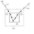
一方、ポインタ領域通過検出手段2は、ポインタ位置入力手段1によるポインタ10の位置と、画面内のオブジェクト12に関連付けてその周辺に設定される特定の領域13との接触状態を検出するもので、ポインタ10がこの特定の領域13の境界領域を通過した場合に、これを検出して、ポインタ10が領域13の中にあるのか、外にあるのかの情報を含めて、ポインタ位置蓄積手段3およびジェスチャ認識手段4に与える。
【0016】
その結果、ポインタ位置蓄積手段3は、ポインタ10の領域13内部における位置を、その軌跡として蓄積する。
【0017】
ジェスチャ認識手段4は、ポインタ領域通過検出手段2とポインタ位置蓄積手段3の各出力に基づいて、ポインタ10の軌跡11を判別し、ある入力の意味に関連付けられている操作の特定のジェスチャを認識すると、その認識結果を処理部5に与える。
【0018】
処理部5は、操作の特定の意味をジェスチャ認識手段4から受け取ると、これを位置情報以外の操作入力として捉え、これを表示部6に与えると共に、操作入力に対応する処理を実行する。
【0019】
さて、領域13は、画面内の対象となるオブジェクト12よりやや大きめの範囲に設定されている。そして、ポインタの軌跡11が図2のように描かれる場合を想定すると、ポインタ10が位置14に至った時に、ポインタ領域通過検出手段2により領域13に入ったことが検出され、ポインタ10が位置15に至った時に、領域13から出たことが検出される。
【0020】
ポインタ位置蓄積手段3は、ポインタ10が領域13の領域内に入ったことを知らせる信号に基づいてポインタ10の位置の蓄積を始め、ポインタ10が領域13から出たことを知らせる信号に基づいて蓄積を停止する。図2の例では、ポインタ10が位置14に到達した時点から、位置15に至るまでのポインタ10の位置、つまり図面に黒丸で示される位置が蓄積される。
【0021】
以上のようにして、蓄積されたポインタ10の位置の時系列的な変化が、ジェスチャ認識手段4に読み込まれ、領域13内におけるポインタ10のジェスチャが、予め設定された、意味を持った特徴的な動きであるか否かを判定する。
【0022】
例えば、位置の移動ベクトルを考える場合、領域13に入った時と、出た時では、ベクトルの向きは反対方向に近い。これに対して、領域13内で、急激に方向が変化するような軌跡11が捉えられた場合、このジェスチャは、例えば「チェックマーク」であると判定される。
【0023】
このジェスチャが領域13内にあるオブジェクト12に対する何らかのアクションであると判断された場合、その情報は処理部5に伝達され、処理部5は対応するオブジェクト12に関連付けられた特定の操作を行う。例えば、このジェスチャが、対象となるファイルのオープンに対応するものであれば、オブジェクト12が示すファイルをオープンすることになる。
【0024】
表示部6は、ポインタ10の位置を画面に表示するのはもちろんであるが、ポインタ10の領域13に対する関係、例えば領域13に入っている、入っていないなどや、ジェスチャの認識結果などに基づく適切なフィードバックを表示を画面上で行う。
【0025】
さて、先にも述べたように、ポインタ位置入力手段1は、手指を利用するFPIに限らず、マウスやトラックボールやペン入力のタブレットなど、一般に多くら用いられている入力方式や、空間マウスなどに適用可能である。そして、FPIと同様に、従来、他の操作ボタンを必要としていた空間マウスの場合に、顕著な効果を得ることができる。
【0026】
さて、ポインタ領域通過検出手段2は、画面の中の予め定められた領域13と、ポインタ10の接触状態を検出するものであるが、その検出の方法についてはさまざまな方式が考えられる。例えば、先に説明したように、ポインタ10が領域13に入ったことと、領域13から出たことを検出する代わりに、ポインタ10が領域13の内部にあるか否かを検出するようにしてもよい。
【0027】
また、ここで言う領域13は、矩形の領域に限らず、丸や三角やその他の形状の領域であっても、線や点で特定される領域であってもよい。つまり、オブジェクト12に対して、特定の位置関係にある線分や、点を設定しておき、これらの線分や点に対して、ポインタ10がどのように動いたかを検出してジェスチャ判定するようにすることもできる。
【0028】
また、上記実施形態では、オブジェクト12に対して、領域13が大きな面積で設定されているが、領域13はオブジェクト12よりも小さな領域であってもよいし、またオブジェクト12と必ずしも重ならなくてもよい。つまり、領域13がオブジェクト12に対して特定の位置関係にあることが予め分かっていれば、操作者はオブジェクト12に関係する意味のある操作を、領域13に対して行うことができる。
【0029】
なお、上記実施形態では、ポインタ位置蓄積手段3の動作については、ポインタ領域通過検出手段2からの領域通過情報に基づいて、ポインタ10の位置を、数ポイント記憶し、その蓄積情報をジェスチャ認識手段4に出力するような場合を例示したが、ポインタ位置蓄積手段3の制御のために必ずしもポインタ領域通過検出手段2からの領域通過情報を用いる必要はなく、ポインタ位置蓄積手段3で常にポインタ10の軌跡を過去の数ポイント分記録蓄積しておき、ポインタ領域通過検出手段2からジェスチャ認識手段4に領域内通過を示す信号が与えられた時点で、ジェスチャ認識手段4によりポインタ位置蓄積手段3の蓄積情報を読み出し、ジェスチャ判定するようにしてもよい。
【0030】
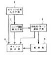
図3は、本発明の実施形態2の情報入力装置のブロック図である。
図3の構成と、動作について、図4の説明図にしたがって説明する。
本実施形態の場合も、図4に示すように、画面内のオブジェクトに関連づけられた領域13が設定されており、これとポインタ10の位置関係によって、位置情報以外の特定の操作を入力指定できるようになっている。
【0031】
本実施形態2の場合、画面内に設定された領域13は、1つ以上の辺、つまりエッジで囲まれており、ポインタ10が、領域13の内側にあるか、外側にあるかだけでなく、どのエッジを、どの方向に通過したのかの情報に基づいて、特定の意味を持った操作入力の内容を判断するようにしている。
【0032】
図2において、エッジ通過検出手段7は、ポインタ10が領域13のエッジを通過したことを検出して、ポインタ10が、どのエッジを、どの方向に通過したかを時系列パターン解析手段8に報知する。
【0033】
なお、エッジ通過検出手段7は、領域エッジデータを、予め登録してあり、この領域エッジデータを参照しながら、通過エッジと方向を検出する。したがって、領域13が、矩形以外の多角形の場合、領域13は多角形の形状に応じた数のエッジを持っている訳であるが、この場合も、多角形の登録データに基づいてポインタ10の通過エッジと、通過方向を検出することができる。
【0034】
なお、領域13として、円形や楕円形を設定している場合も、稜線をいくつかの曲線状の線分に分割して、それぞれを多角形のエッジと想定し、ほぼ同じ大きさの多角形をあてはめることにより、エッジ検出と見做すことができる。
【0035】
また、多角形の領域13に対して、ひとつの辺をひとつのエッジに割り当てる代わりに、複数の辺をまとめて1つのエッジと見做しても、逆にひとつの辺に、複数のエッジを割り当てるようにしてもよく、これはエッジ通過検出手段7に登録されたデータにより、任意に設定可能である。
【0036】
今、図4に示すように、矩形の領域13を考えると、4本の辺に4つのエッジを割り当てることができる。
【0037】
さて、ポインタ10が領域13に入り、出て行く場合には、ポインタ10の軌跡は4つのエッジに対して、さまざまな関係を持つ。例えば、図5の説明図に示すように、領域13の上のエッジをT、右のエッジをR、左のエッジをL、下のエッジをBとした場合、4つのそれぞれのエッジT、B、L、Rに対して、ポインタ10は、外から内に入る場合のIと、内から外に出る場合のOで、2つの場合が存在する。つまり、ポインタ10が領域13に対して、外から内に入る場合、エッジによりT、B、L、Rの4種類の意味を持たせることが可能であり、ポインタ10が領域13に対して、内から外に出る場合、エッジによりT、B、L、Rの4種類の意味を持たせることができる。したがって、ポインタ10が領域13の内に入って、次に外に出て行く場合、必ず2つのエッジを通過するので、それぞれの通過エッジによって全部で16種類の意味合いを持たせることが可能である。
【0038】
例えば、図4に示すように、ポインタ10が軌跡9に沿って、エッジTから入り、エッジTから出ていった場合、「IT、OT」と表現でき、ポインタ10が軌跡17に沿って、エッジLから入り、エッジBから出ていった場合、「IL、OB」と表現できる。
【0039】
時系列パターン解析手段8は、この通過情報の時系列パターンから、単純なパターンを排除し、特徴的なものだけに特定の操作の意味を割り当てている。
【0040】
例えば、あるドキュメントを表すオブジェクトに対して、それを選択してオープンする、という動作を割り当てるために、オブジェクトに対応づけた領域13に対して、「IT、OT」を割り当てる。
【0041】
これは、図6の説明図に示すように、ポインタ10が、軌跡9に沿って、領域13に上から入り、上から出ていった場合を表すが、このようなポインタ10の動きに対応して、時系列パターン解析手段8は処理部5に対して、オープン操作に対応する解析結果を送出し、処理部5はオブジェクトに対応するファイルのオープンを実行する。
【0042】
また、あるオブジェクトに対して、それを選択してドラッグする、という動作を割り当てるために、オブジェクトに対応づけた領域13に対して、「IB、OB」を割り当てる。
【0043】
これは、図6の説明図に示すように、ポインタ10が、軌跡18に沿って領域13に下から入り、下から出ていった場合を表すが、このようなポインタ10の動きに対応して、時系列パターン解析手段8は処理部5に対して、ドラッグ操作に対応する解析結果を送出し、処理部5は、その後のポインタ10の動きに対応して、オブジェクトのドラッグを実行する。
【0044】
ここで、ポインタ10の単純な動きを排除して、あえて複雑な特徴的な動きのみを、特定の操作に結びつけるのかについての理由を説明する。
【0045】
例えば、単純にポインタ10がオブジェクトに関連づけられた領域13の上を通過しただけで、関連するオブジェクトに対応する操作が選択されるように設定した場合、操作者が、単純にポインタ10を移動させたいだけの場合は、領域13を避けてこれを実行する必要がある。これは、操作者に無用の負担をかけるだけでなく、場合によっては、操作者の意図しない誤操作を招く可能性が高い。
【0046】
以上のような理由から、時系列パターン解析手段8は、ポインタ10の単純な動き、例えば、ポインタ10の上下左右斜めの単純な通過などは、特定の操作の意味付けから排除している。つまり、図4に示す軌跡17のような場合、動きが単純であり、単なるポインタ10の通過であると見做して、時系列パターン解析手段8は反応しない。
【0047】
なお、本実施形態では、複数の軌跡に対して、複数の意味を持たせる場合を例示したが、全ての特徴的なポインタ10の動きに対して、常に同じ意味を持たせるようにしてもよい。つまり、「IT、OT」、「IB、OB」、「IL、OL」や「IR、OR」が検出された場合、常にファイルのオープンの意味を割り当てるようにしてもよい。
【0048】
一方、動きの方向毎に意味を割り当てるやり方も考えられる。つまり、上下の動き「IT、OT」や「IB、OB」にファイルのオープン、左右の動き「IL、OL」や「IR、OR」にオブジェクトのドラッグを割り当てるようにしてもよい。
【0049】
図7は、量を入力する場合、例えば音量、表示輝度、パラメータ設定などによく用いられるスライダを操作する場合の状態を示す説明図である。
【0050】
まず、同図(A)に示すように、ポインタ10を、スライダの現在位置を示すオブジェクト、つまり現在位置オブジェクトに重ねられた領域13に対して、矢印Aに示すように、上エッジから中にいれる。これが「IT」動作となる。なお、この場合は、オブジェクトとこれを検出するための領域13を同じサイズにしてある。
【0051】
その結果、図3のエッジ通過検出手段7は、ポインタ10が領域13に上から入ったことを検出して、時系列パターン解析手段8を通じて処理部5にそのことを示す信号を送出し、スライダをアクティブにする。
【0052】
しかる後は、同図(B)に示すように、ポインタ10を左右に動かすことにより、スライダを矢印B方向に左右に動かし、所望の量を操作選択することができるようになる。
【0053】
スライダを所望の位置まで動かしたら、同図(C)に示すように、ポインタ10を、矢印C方向に、下エッジから領域13の外に出す。これが「OB」動作となる。その結果、このポインタ10の軌跡はエッジ通過検出手段7により検出され、時系列パターン解析手段8、処理部5を通じて、スライダの位置の確定動作が行われ、量の入力が終了する。
【0054】
なお、ポインタ10を下エッジから外に出す代わりに、上エッジから外に出した場合、これまでのスライダの動きをキャンセルして、スライダを動かす前の状態に戻すようにしてもよい。このようにポインタ10の領域13に対する動きに意味を与えるのは、エッジ通過検出手段7、時系列パターン解析手段8、処理部5の制御プログラムであり、任意に設定可能である。
【0055】
さて、指の動きでポインタ10を制御している場合に、スライダを左右に動かす場合に、指の動きが上下にずれてしまうと、領域13の上下の範囲を越えてしまうことがある。その結果、操作者の意図に反して、量が確定したり、スライダの動きがキャンセルされてしまったりと、不都合な動きになり易い。この うに、領域13の範囲からちょっとはずれただけで、制御不可能になってしまうのでは、非常に使いにくいので、以下のような処理を行うのが好ましい。
【0056】
まず、ポインタ10を領域13の上エッジから現在位置オブジェクトに入れた場合、以降のポインタ10の移動については、量の選択を行う左右方向のみを量子化するように設定する。ポインタ10の移動方向が上下方向から一定の範囲にある場合は、左右方向の動きのみを投影した量だけオブジェクトを動かし、ポインタ10も左右のみに動かす。ポインタ10の移動方向が上下方向から一定の範囲内にある限りは、左右方向にポインタを移動し、左右の動きが止まった場合に、始めてポインタ10の上下方向の移動量を検出するようにし、その後、ポインタ10が領域13の上下のエッジを通過した場合に、量の確定かスライダの移動のキャンセルを行なう。その結果、スライダを操作する場合の操作性を大幅に向上することができる。
【0057】
なお、スライダ操作の際のポインタ10の左右の動きの傾向の検出により、制御モードを切り替える代わりに、スライダ操作のために、ポインタ10が領域13に入った場合、領域13の上下の範囲を広げて、ポインタ10が容易に領域13から外れないようにしても同様の効果を得ることができる。
【0058】
なお、スライダ操作以外にも、色選択やメニューバー選択など、さまざまな入力操作が考えられるが、いずれにせよ、オブジェクトに関連付けて設定される領域に対するポインタの特徴的な動きを、操作の意味に関連付けて登録しておくことにより、位置情報以外のさまざまな操作入力を行うことが可能である。
【0059】
【発明の効果】
以上述べたように、本発明の情報入力装置は、オブジェクトに対応して配置される領域におけるポインタの動きや、この領域のエッジに対するポインタの出入方向の組み合わせから、ポインタの特徴的な動きを抽出し、この抽出情報に基づいて、位置情報以外の特定の意味を電子機器に与えるように構成したので、マウスボタンのような特別な入力手段によらずにオブジェクトに対応する意味入力が可能となり、操作性を大幅に向上できるという効果がある。
【図面の簡単な説明】
【図1】本発明の実施形態1の情報入力装置のブロック図である。
【図2】図1の構成において、特定領域に対するポインタの軌跡を検出する場合の説明図である。
【図3】本発明の実施形態2の情報入力装置のブロック図である。
【図4】実施形態2における、特定領域に対するポインタの軌跡検出の方式の説明図である。
【図5】実施形態2における、特定領域に対するポインタの軌跡の組み合わせの説明図である。
【図6】実施形態2における、特定領域に対するポインタの軌跡の意味割り当て方式の説明図である。
【図7】実施形態2の、スライダ操作への適用例の説明図である。
【符号の説明】
1 ポインタ位置入力手段
2 ポインタ領域通過検出手段
3 ポインタ位置蓄積手段
4 ジェスチャ認識手段
5 処理部
6 表示部
7 エッジ通過検出手段
8 時系列パターン解析手段
9、11、17、18 軌跡
10 ポインタ
12 オブジェクト
13 領域[0001]
BACKGROUND OF THE INVENTION
The present invention relates to an information input apparatus and method, and more particularly to an information input apparatus and method for controlling a pointer operation to an information display screen for operating an electronic device such as a personal computer.
[0002]
[Prior art]
Conventionally, when operating an electronic device such as a personal computer, a pointer or cursor on an information display screen is moved using a pointing device such as a mouse or a trackball, and an object on the screen is designated to operate a button. By adding, a specific work is started or an object is moved. Such a method is called a GUI (Graphical User Interface), and is one of the methods that are widely used at present as one operation mode of a personal computer.
[0003]
In the future, as electronic devices become smaller and can be freely carried, it can be easily predicted that cases where conventional pointing devices will not be sufficient will appear. For example, since a mouse requires a plane with a certain size for operation, it is not suitable for a portable device. On the other hand, in the case of a trackball or a small joystick, the movement of the operating hand is different from the movement of the pointer, so that it is not suitable for inputting a gesture for instructing a specific work. In the case of using a pen device, there is an inconvenience of taking out the pen every time it is used, and it is difficult to say that it is an optimal method in consideration of the possibility of the pen being lost.
[0004]
As an information input method, the inventor of the present case is a method already proposed in Japanese Patent Application No. 7-250418, etc., but the operator's hand is illuminated and the reflected light is captured as an image. There is a fingerprinting interface (FPI) in which the position of the pointer is obtained by image processing. This is because the movement of the pointer can be controlled by the movement of the fingers, so that the movement of a part of the operator's body can be captured and information can be input to the electronic device without using a special tool. In particular, there is an advantage that the operability can be greatly improved in a portable information device.
[0005]
However, even in this FPI, when operating the screen, the pointer is not operated using only the movement of the finger, but it is necessary to make the pointer meaningful in combination with the operation of other buttons. There was a limit to the improvement in operability. In other words, when holding the portable information device with the left hand and moving the pointer with the right hand, it is necessary to perform button operation with the left hand in parallel. There is a problem that it becomes difficult to specify an object or the screen shakes every time a button is operated.
[0006]
On the other hand, in the case of a pen device, it is configured to input position information based on information on contact and non-contact with the tablet. In this case, too, in order to correspond to a specific operation other than position information, There is a problem that it is necessary to prepare a switch to be turned on when the pen is first pressed against the tablet, or to provide another operation switch on the pen body, and the operability cannot be improved decisively.
[0007]
The same problem is also evident in the so-called spatial mouse that operates the pointer with a remote controller equipped with a gyroscope or infrared light emitting unit. When a meaningful operation is applied to the object specified by the pointer, a separate button is used. Therefore, an operation part such as the above is necessary, which is an impediment to improving operability.
[0008]
[Problems to be solved by the invention]
As described above, the conventional information input device includes a mouse button or an input unit corresponding to the mouse button as an input unit for a specific operation other than the position information, and processes the position information and the button operation in association with each other. Thus, particularly in the case of a portable information device or the like, there has been a problem that the operation becomes complicated or is not suitable depending on the operation content.
[0009]
The present invention solves the problems of the prior art as described above, eliminates an operation part for inputting information other than position information such as a button, and a function for inputting position information, By simply adding a function to discriminate gesture input that directs a specific operation based on changes in position information, it is possible to specify an object on the screen, perform an operation input related to this, and operate the electronic device comfortably It is an object of the present invention to provide an information input apparatus and method.
[0010]
[Means for Solving the Problems]
In order to achieve the above object, the present invention sets pointer position input means for inputting pointer position information indicating an arbitrary position on the display screen, and a specific area set in association with the object on the display screen. Anda pointer area passage detecting means for detecting that the pointer has entered the specific area and that the pointer has exited from the specific area, and the pointer has entered the specific area based on the detection result of the pointer area passage detection means. Provided is an information input devicecomprising pointer position storage means for storing a trajectory until exiting and recognition means for recognizing meaning by analyzingthe trajectoryaccumulated by the pointer position storage means It is.
[0011]
Further, according to the present invention, the pointer position information indicating the arbitrary position of the display screen is input by the pointer position input means, and the specific area set in association with the object on the display screen by thepointer area passage detection means. Anddetecting that the pointer has entered and exited from the specific area, and the pointer is stored in thespecific area based on the detection result of the pointer area passage detecting means by thepointer position accumulating means.accumulated trajectory to exit from entering, by the recognition unit, by analyzingthe trajectory, there is provided an information input method is characterized in that so as to recognize the meaning.
[0012]
DETAILED DESCRIPTION OF THE INVENTION
Hereinafter, embodiments of the present invention will be described with reference to the drawings.
FIG. 1 is a block diagram of an information input apparatus according to the first embodiment of the present invention.
The configuration and operation of FIG. 1 will be described with reference to the explanatory diagram of FIG.
The pointer
[0013]
The pointer position input means 1 may be a conventionally known mouse or pen input device, but a more preferable application example is to detect the position and movement of the operator's fingertip as described above. There is an FPI that determines the position of the
[0014]
A signal indicating the position of the
[0015]
On the other hand, the pointer area passage detection means 2 detects the contact state between the position of the
[0016]
As a result, the pointer
[0017]
The
[0018]
When the
[0019]
Now, the
[0020]
The pointer
[0021]
As described above, the time-series change in the accumulated position of the
[0022]
For example, when considering a position movement vector, the direction of the vector is close to the opposite direction when entering and exiting the
[0023]
When it is determined that this gesture is an action for the object 12 in the
[0024]
The
[0025]
As described above, the pointer position input means 1 is not limited to the FPI using fingers, but is generally used in many input methods such as a mouse, a trackball, a pen input tablet, and a spatial mouse. It is applicable to. As in the case of FPI, a significant effect can be obtained in the case of a spatial mouse that conventionally requires other operation buttons.
[0026]
The pointer area passage detection means 2 detects a contact state between a
[0027]
Further, the
[0028]
In the above embodiment, the
[0029]
In the above-described embodiment, the operation of the pointer position accumulating means 3 is based on the area passage information from the pointer area
[0030]
FIG. 3 is a block diagram of the information input apparatus according to the second embodiment of the present invention.
The configuration and operation of FIG. 3 will be described with reference to the explanatory diagram of FIG.
Also in the present embodiment, as shown in FIG. 4, an
[0031]
In the case of the second embodiment, the
[0032]
In FIG. 2, the edge passage detection means 7 detects that the
[0033]
The edge passage detection means 7 registers region edge data in advance, and detects the passage edge and direction while referring to the region edge data. Therefore, when the
[0034]
Note that even when a circle or an ellipse is set as the
[0035]
Also, instead of assigning one side to one edge for the
[0036]
Now, as shown in FIG. 4, when a
[0037]
Now, when the
[0038]
For example, as shown in FIG. 4, when the
[0039]
The time series pattern analyzing means 8 excludes simple patterns from the time series pattern of the passage information, and assigns the meaning of a specific operation only to characteristic ones.
[0040]
For example, in order to assign an operation of selecting and opening an object representing a certain document, “IT, OT” is assigned to the
[0041]
As shown in the explanatory diagram of FIG. 6, this represents a case where the
[0042]
In addition, in order to assign an operation of selecting and dragging an object, “IB, OB” is assigned to the
[0043]
As shown in the explanatory diagram of FIG. 6, this represents a case where the
[0044]
Here, the reason why the simple movement of the
[0045]
For example, when the setting is made so that the operation corresponding to the related object is selected simply by passing the
[0046]
For the reasons described above, the time-series
[0047]
In the present embodiment, the case where a plurality of trajectories are given a plurality of meanings is illustrated, but the same meaning may always be given to all the characteristic movements of the
[0048]
On the other hand, a method of assigning meaning for each direction of movement is also conceivable. That is, a file open may be assigned to the up and down movements “IT, OT” and “IB, OB”, and an object drag may be assigned to the left and right movements “IL, OL” and “IR, OR”.
[0049]
FIG. 7 is an explanatory diagram showing a state when a slider is often used for inputting volume, for example, volume, display brightness, parameter setting, and the like.
[0050]
First, as shown in FIG. 5A, the
[0051]
As a result, the edge passage detection means 7 in FIG. 3 detects that the
[0052]
Thereafter, as shown in FIG. 5B, by moving the
[0053]
When the slider is moved to a desired position, the
[0054]
Instead of moving the
[0055]
When the
[0056]
First, when the
[0057]
When the
[0058]
In addition to the slider operation, various input operations such as color selection and menu bar selection are conceivable, but in any case, the characteristic movement of the pointer with respect to the area set in association with the object is the meaning of the operation. By registering in association, various operation inputs other than position information can be performed.
[0059]
【The invention's effect】
As described above, the information input device of the present invention extracts a pointer's characteristic movement from a combination of a pointer movement in an area arranged corresponding to an object and a pointer entry / exit direction with respect to an edge of this area. And, based on this extracted information, because it is configured to give the electronic device a specific meaning other than the position information, meaning input corresponding to the object is possible without using a special input means such as a mouse button, There is an effect that operability can be greatly improved.
[Brief description of the drawings]
FIG. 1 is a block diagram of an information input device according to a first embodiment of the present invention.
FIG. 2 is an explanatory diagram in the case of detecting a locus of a pointer with respect to a specific area in the configuration of FIG.
FIG. 3 is a block diagram of an information input device according to a second embodiment of the present invention.
FIG. 4 is an explanatory diagram of a method for detecting a locus of a pointer with respect to a specific area in the second embodiment.
FIG. 5 is an explanatory diagram of a combination of pointer trajectories with respect to a specific area in the second embodiment.
FIG. 6 is an explanatory diagram of a meaning assignment method of a pointer trajectory with respect to a specific area in the second embodiment.
FIG. 7 is an explanatory diagram of an application example of the second embodiment to a slider operation.
[Explanation of symbols]
DESCRIPTION OF
Claims (5)
Translated fromJapanesePriority Applications (2)
| Application Number | Priority Date | Filing Date | Title |
|---|---|---|---|
| JP24386996AJP3904637B2 (en) | 1996-09-13 | 1996-09-13 | Information input device and method |
| US08/928,140US5990893A (en) | 1996-09-13 | 1997-09-12 | Data input device and method |
Applications Claiming Priority (1)
| Application Number | Priority Date | Filing Date | Title |
|---|---|---|---|
| JP24386996AJP3904637B2 (en) | 1996-09-13 | 1996-09-13 | Information input device and method |
Publications (2)
| Publication Number | Publication Date |
|---|---|
| JPH1091320A JPH1091320A (en) | 1998-04-10 |
| JP3904637B2true JP3904637B2 (en) | 2007-04-11 |
Family
ID=17110197
Family Applications (1)
| Application Number | Title | Priority Date | Filing Date |
|---|---|---|---|
| JP24386996AExpired - Fee RelatedJP3904637B2 (en) | 1996-09-13 | 1996-09-13 | Information input device and method |
Country Status (2)
| Country | Link |
|---|---|
| US (1) | US5990893A (en) |
| JP (1) | JP3904637B2 (en) |
Families Citing this family (59)
| Publication number | Priority date | Publication date | Assignee | Title |
|---|---|---|---|---|
| US8352400B2 (en) | 1991-12-23 | 2013-01-08 | Hoffberg Steven M | Adaptive pattern recognition based controller apparatus and method and human-factored interface therefore |
| KR100595922B1 (en) | 1998-01-26 | 2006-07-05 | 웨인 웨스터만 | Method and apparatus for integrating manual input |
| US6181344B1 (en)* | 1998-03-20 | 2001-01-30 | Nuvomedia, Inc. | Drag-and-release method for configuring user-definable function key of hand-held computing device |
| US6331867B1 (en)* | 1998-03-20 | 2001-12-18 | Nuvomedia, Inc. | Electronic book with automated look-up of terms of within reference titles |
| US6154214A (en)* | 1998-03-20 | 2000-11-28 | Nuvomedia, Inc. | Display orientation features for hand-held content display device |
| US6356287B1 (en)* | 1998-03-20 | 2002-03-12 | Nuvomedia, Inc. | Citation selection and routing feature for hand-held content display device |
| US7904187B2 (en) | 1999-02-01 | 2011-03-08 | Hoffberg Steven M | Internet appliance system and method |
| US7046229B1 (en)* | 1999-04-20 | 2006-05-16 | Microsoft Corporation | Computer input device providing absolute and relative positional information |
| US6396523B1 (en) | 1999-07-29 | 2002-05-28 | Interlink Electronics, Inc. | Home entertainment device remote control |
| US6901561B1 (en)* | 1999-10-19 | 2005-05-31 | International Business Machines Corporation | Apparatus and method for using a target based computer vision system for user interaction |
| US6765557B1 (en) | 2000-04-10 | 2004-07-20 | Interlink Electronics, Inc. | Remote control having touch pad to screen mapping |
| EP1246048A1 (en)* | 2001-03-26 | 2002-10-02 | SAP Aktiengesellschaft | Method and computer system for executing functions for objects based on the movement of an input device |
| JP2003283615A (en) | 2002-03-27 | 2003-10-03 | Nec Corp | Mobile communication terminal |
| US7757186B2 (en)* | 2003-07-07 | 2010-07-13 | Apple Inc. | Automatic mapping of pointing devices to multiple displays |
| US7565622B2 (en)* | 2003-07-10 | 2009-07-21 | Lenovo (Singapore) Pte Ltd. | Method and apparatus for modification of pointing device functions in conjunction with dynamic sorting, displaying, listing, and activation |
| TWI227838B (en)* | 2003-07-30 | 2005-02-11 | Fujitsu Ltd | Certifying method, certifying device, and computer readable storing medium |
| US7707039B2 (en) | 2004-02-15 | 2010-04-27 | Exbiblio B.V. | Automatic modification of web pages |
| US8442331B2 (en) | 2004-02-15 | 2013-05-14 | Google Inc. | Capturing text from rendered documents using supplemental information |
| JP2005215749A (en)* | 2004-01-27 | 2005-08-11 | Nec Corp | Selection system and selection method of operating element |
| US10635723B2 (en) | 2004-02-15 | 2020-04-28 | Google Llc | Search engines and systems with handheld document data capture devices |
| US7812860B2 (en) | 2004-04-01 | 2010-10-12 | Exbiblio B.V. | Handheld device for capturing text from both a document printed on paper and a document displayed on a dynamic display device |
| US20060081714A1 (en) | 2004-08-23 | 2006-04-20 | King Martin T | Portable scanning device |
| US8081849B2 (en) | 2004-12-03 | 2011-12-20 | Google Inc. | Portable scanning and memory device |
| US20060098900A1 (en) | 2004-09-27 | 2006-05-11 | King Martin T | Secure data gathering from rendered documents |
| US9143638B2 (en) | 2004-04-01 | 2015-09-22 | Google Inc. | Data capture from rendered documents using handheld device |
| US7990556B2 (en) | 2004-12-03 | 2011-08-02 | Google Inc. | Association of a portable scanner with input/output and storage devices |
| US8146156B2 (en) | 2004-04-01 | 2012-03-27 | Google Inc. | Archive of text captures from rendered documents |
| US9116890B2 (en) | 2004-04-01 | 2015-08-25 | Google Inc. | Triggering actions in response to optically or acoustically capturing keywords from a rendered document |
| US7894670B2 (en) | 2004-04-01 | 2011-02-22 | Exbiblio B.V. | Triggering actions in response to optically or acoustically capturing keywords from a rendered document |
| US9008447B2 (en) | 2004-04-01 | 2015-04-14 | Google Inc. | Method and system for character recognition |
| US8713418B2 (en) | 2004-04-12 | 2014-04-29 | Google Inc. | Adding value to a rendered document |
| US8489624B2 (en) | 2004-05-17 | 2013-07-16 | Google, Inc. | Processing techniques for text capture from a rendered document |
| US8620083B2 (en) | 2004-12-03 | 2013-12-31 | Google Inc. | Method and system for character recognition |
| US8874504B2 (en) | 2004-12-03 | 2014-10-28 | Google Inc. | Processing techniques for visual capture data from a rendered document |
| US8346620B2 (en) | 2004-07-19 | 2013-01-01 | Google Inc. | Automatic modification of web pages |
| US7721197B2 (en)* | 2004-08-12 | 2010-05-18 | Microsoft Corporation | System and method of displaying content on small screen computing devices |
| US8169410B2 (en)* | 2004-10-20 | 2012-05-01 | Nintendo Co., Ltd. | Gesture inputs for a portable display device |
| JP2006129942A (en)* | 2004-11-02 | 2006-05-25 | Namco Ltd | PROGRAM, INFORMATION STORAGE MEDIUM, AND GAME DEVICE |
| JP2008527528A (en)* | 2005-01-05 | 2008-07-24 | ゼ ウー アン | Character input method and apparatus using pointing input means |
| US7750893B2 (en)* | 2005-04-06 | 2010-07-06 | Nintendo Co., Ltd. | Storage medium storing input position processing program, and input position processing device |
| JP4719494B2 (en)* | 2005-04-06 | 2011-07-06 | 任天堂株式会社 | Input coordinate processing program and input coordinate processing apparatus |
| US7543248B2 (en)* | 2005-05-31 | 2009-06-02 | Fuji Xerox Co., Ltd. | User-machine interface |
| EP2067119A2 (en) | 2006-09-08 | 2009-06-10 | Exbiblio B.V. | Optical scanners, such as hand-held optical scanners |
| US7855718B2 (en) | 2007-01-03 | 2010-12-21 | Apple Inc. | Multi-touch input discrimination |
| US8130203B2 (en) | 2007-01-03 | 2012-03-06 | Apple Inc. | Multi-touch input discrimination |
| JP5225820B2 (en)* | 2008-11-25 | 2013-07-03 | アイシン精機株式会社 | Input device, vehicle periphery monitoring device, icon switch selection method and program |
| JP5178484B2 (en)* | 2008-12-08 | 2013-04-10 | キヤノン株式会社 | Information processing apparatus and information processing method |
| DE202010018601U1 (en) | 2009-02-18 | 2018-04-30 | Google LLC (n.d.Ges.d. Staates Delaware) | Automatically collecting information, such as gathering information using a document recognizing device |
| CN102349087B (en) | 2009-03-12 | 2015-05-06 | 谷歌公司 | Automatically provide content associated with captured information, such as information captured in real time |
| US8447066B2 (en) | 2009-03-12 | 2013-05-21 | Google Inc. | Performing actions based on capturing information from rendered documents, such as documents under copyright |
| US9081799B2 (en) | 2009-12-04 | 2015-07-14 | Google Inc. | Using gestalt information to identify locations in printed information |
| US9323784B2 (en) | 2009-12-09 | 2016-04-26 | Google Inc. | Image search using text-based elements within the contents of images |
| CN101825960B (en)* | 2010-04-23 | 2012-07-18 | 潘天华 | Method for realizing computer function control based on three-point state information of mouse |
| CN102385471B (en)* | 2010-08-31 | 2016-01-20 | 腾讯科技(深圳)有限公司 | A kind of method and apparatus controlling to start |
| WO2012108552A1 (en)* | 2011-02-08 | 2012-08-16 | Lg Electronics Inc. | Display device and control method thereof |
| JP5790257B2 (en)* | 2011-07-29 | 2015-10-07 | 富士通株式会社 | Character input device, character input program, and character input method |
| CN102662581B (en)* | 2012-03-31 | 2015-06-24 | 北京奇虎科技有限公司 | Method and system for controlling with mouse input |
| JP5390674B2 (en)* | 2012-08-24 | 2014-01-15 | 株式会社東芝 | Information processing apparatus, information processing method, and program |
| CN115766158A (en)* | 2021-04-29 | 2023-03-07 | 中原工学院 | System and method for network information security intrusion detection |
Family Cites Families (6)
| Publication number | Priority date | Publication date | Assignee | Title |
|---|---|---|---|---|
| US5550930A (en)* | 1991-06-17 | 1996-08-27 | Microsoft Corporation | Method and system for training a handwriting recognizer at the time of misrecognition |
| US5592566A (en)* | 1992-05-27 | 1997-01-07 | Apple Computer, Incorporated | Method and apparatus for computerized recognition |
| US5583946A (en)* | 1993-09-30 | 1996-12-10 | Apple Computer, Inc. | Method and apparatus for recognizing gestures on a computer system |
| DE69426919T2 (en)* | 1993-12-30 | 2001-06-28 | Xerox Corp | Apparatus and method for performing many chaining command gestures in a gesture user interface system |
| US5687254A (en)* | 1994-06-06 | 1997-11-11 | Xerox Corporation | Searching and Matching unrecognized handwriting |
| JPH0844490A (en)* | 1994-07-28 | 1996-02-16 | Matsushita Electric Ind Co Ltd | Interface device |
- 1996
- 1996-09-13JPJP24386996Apatent/JP3904637B2/ennot_activeExpired - Fee Related
- 1997
- 1997-09-12USUS08/928,140patent/US5990893A/ennot_activeExpired - Lifetime
Also Published As
| Publication number | Publication date |
|---|---|
| JPH1091320A (en) | 1998-04-10 |
| US5990893A (en) | 1999-11-23 |
Similar Documents
| Publication | Publication Date | Title |
|---|---|---|
| JP3904637B2 (en) | Information input device and method | |
| US11513601B2 (en) | Method and system for human-to-computer gesture based simultaneous interactions using singular points of interest on a hand | |
| JP4899806B2 (en) | Information input device | |
| KR101437760B1 (en) | Gesture recognition apparatus, electronic device, gesture recognition method, and computer-readable recording medium for control program | |
| EP2743799B1 (en) | Control apparatus, vehicle, and portable terminal using hand information for command generation | |
| JP6159323B2 (en) | Information processing method and information processing apparatus | |
| KR100858358B1 (en) | Method and apparatus for user-interface using the hand trace | |
| US20090153655A1 (en) | Gesture recognition apparatus and method thereof | |
| US20140218315A1 (en) | Gesture input distinguishing method and apparatus in touch input device | |
| JP5817149B2 (en) | Projection device | |
| JP2012185630A (en) | Projection device | |
| JP2012027515A (en) | Input method and input device | |
| JP6452369B2 (en) | Information processing apparatus, control method therefor, program, and storage medium | |
| KR101314641B1 (en) | Operating method using user gesture and digital device thereof | |
| JP3400111B2 (en) | Input device for portable electronic device, input method for portable electronic device, and portable electronic device | |
| JP2005092419A (en) | Information processing apparatus and program | |
| JPH10269021A (en) | Touch panel input device | |
| CN105808129A (en) | Method and device for rapidly starting software functions by utilizing gestures | |
| US20220129109A1 (en) | Information processing apparatus, information processing method, and recording medium | |
| KR100939831B1 (en) | Operating input device for reducing input error and information device operation apparatus | |
| US12210722B2 (en) | Position specifying method and program | |
| JPH09237151A (en) | Graphical user interface | |
| CN104731313B (en) | Pass through the exectorial method and apparatus of single-touch gesture | |
| KR19990061763A (en) | Method and device for interface between computer and user using hand gesture | |
| US20250271948A1 (en) | User Interface Device, User Interface System, and Recording Medium |
Legal Events
| Date | Code | Title | Description |
|---|---|---|---|
| A521 | Request for written amendment filed | Free format text:JAPANESE INTERMEDIATE CODE: A523 Effective date:20040114 | |
| A911 | Transfer to examiner for re-examination before appeal (zenchi) | Free format text:JAPANESE INTERMEDIATE CODE: A911 Effective date:20040303 | |
| A912 | Re-examination (zenchi) completed and case transferred to appeal board | Free format text:JAPANESE INTERMEDIATE CODE: A912 Effective date:20040409 | |
| RD02 | Notification of acceptance of power of attorney | Free format text:JAPANESE INTERMEDIATE CODE: A7422 Effective date:20050415 | |
| RD04 | Notification of resignation of power of attorney | Free format text:JAPANESE INTERMEDIATE CODE: A7424 Effective date:20050606 | |
| A61 | First payment of annual fees (during grant procedure) | Free format text:JAPANESE INTERMEDIATE CODE: A61 Effective date:20070110 | |
| LAPS | Cancellation because of no payment of annual fees |